Written Report - University of Florida · Executive Summary Hoodie And The Blowfish is a fish...
38
Written Report Vilija Baublyte EEL 5666 12/12/2003
Transcript of Written Report - University of Florida · Executive Summary Hoodie And The Blowfish is a fish...

Written Report
Vilija Baublyte EEL 5666 12/12/2003

Table of Contents
ABSTRACT........................................................................................................................................ 3
EXECUTIVE SUMMARY ................................................................................................................ 4
INTRODUCTION .............................................................................................................................. 5
INTEGRATED SYSTEM .................................................................................................................. 5
FIGURE 1: HARDWARE INTERFACE........................................................................................... 6
PLATFORM ....................................................................................................................................... 6
ACTUATION ..................................................................................................................................... 7
Feeding Mechanism................................................................................................................ 7 Water Level Sensing ............................................................................................................... 8 Timer Mechanism ................................................................................................................... 9
SENSORS ......................................................................................................................................... 10
PH Sensor.............................................................................................................................. 10 Temperature Sensor .............................................................................................................. 11
BEHAVIORS.................................................................................................................................... 11
CONCLUSION................................................................................................................................. 12
DOCUMENTATION........................................................................................................................ 13
APPENDIX A................................................................................................................................... 14
APPENDIX B................................................................................................................................... 25

Abstract
Hoodie And The Blowfish is a fish feeding robot. He is designed to feed the fish every morning, turn on the aquarium light in the morning and off at night, check water level in the aquarium tank and if needed at more water from the backup tank reserve. The robot will also check the pH level and temperature of the water and display these values on LCD screen.

Executive Summary
Hoodie And The Blowfish is a fish feeding robot. Hoodie and the Blowfish will feed the fish and turn on the aquarium light at user preset time. The aquarium light will be automatically turned off at 11pm at night. The robot will also check the water level in the aquarium and if water level is low, it will add more water to the aquarium from the water reserve tank. The temperature and pH of the water will be checked and displayed on LCD screen. Hoodie and the blowfish uses ATMega8 microcontroller, EMP7032SLC-10 CPLD and EMP7128SLC-7 CPLD. Microcontroller is used for main routine set up, A/D interface for temperature sensor, PWM for servo control used in feeding mechanism and LCD set up. EMP7032SLC-10 CPLD is used for the decoding of pH sensor and water level detection / water pump control. EMP7128SLC-7 CPLD is used for a clock mechanism set up to keep track of time, to allow user to input morning feeding time, to determine when fish should be fed and light should be turned on and send out control signals to turn on the light and feed the fish. This CPLD also allows user to set the timer and to manually turn on and off the aquarium light and feed the fish. Moreover CPLD saves the last time that the fish were fed and allows user to access this information. Note that due to shortage of I/O pins on ATMega8, serial interface between ATMega8 and EMP7128SLC-7 CPLD was implemented. Feeding mechanism is designed as a food container with a cylinder containing a groove attached at the bottom. The cylinder is free to rotate and by rotating dispense flakes/granules to fall into the aquarium set up beneath the mechanism. The mechanism utilizes one servo used to rotate the cylinder. Timer device built in CPLD allows the system to determine when feeding mechanism should be turned on and when aquarium light should be turned on and off. Water level detection is achieved through the use of wires and idea of difference of resistance between the wires in air and in water. Two separate water level detection devices are set up, one to determine water level in the aquarium and one to determine water level in the reservoir tank. From the water level detection mechanisms the control equation for the water pump is set up in CPLD to turn on the water pump when more water is needed in the aquarium. To determine temperature of the water LM34DZ temperature sensor is used. The temperature outputted by the sensor is passed through A/D on ATMega8 and outputted on LCD screen. PH of the water is determined using a digital pH sensor. The sensor has ICL7126A/D which is directly interfaced to seven segment LED screen. The 7 segment LED outputs were taken and decoded in the CPLD and then sent to LCD screen.

Introduction
Hoodie And The Blowfish is a robot witch will feed the aquarium fish when you are busy or away. It was inspired by hassle that one has to go through of finding someone to take care of the fish when you’re not available. The robot will feed the fish at set time in the morning and turn on the aquarium light, turn the aquarium light off at night, check water level in the fish tank and add more water if needed. Moreover Hoodie and the Blowfish will check the quality of the water by checking temperature and pH level and display these values on the LCD screen.
Integrated System Hoodie and the Blowfish uses ATMega8 as its main controller with EMP7032SLC-10 and EMP7128SLC-7 CPLD’s for decoding and other controls. Due to shortage of Input / Output pins on ATMega8, serial interface between the EMP7128SLC-7 CPLD and ATMega8 was set up. Figure 1 displays the general hardware interface with all the sensors. ATMega8 microcontroller receives temperature input to A/D port and generates PWM signal for the servo to actuate feeding mechanism. Microcontroller also interfaces LCD display and serial input from the CPLD. EMP7032SLC-10 CPLD contains the pH sensor decoder. Decoded 7 segment LED lines are combined into one 8 bit value and sent to 7128 CPLD where it is then sent to ATMega8 through serial interface. 7032 CPLD controls the pump on/off signal through a logic equation depending on what values are received by water level detection lines. EMP7128SLC-7 CPLD houses the main timer device. Timer device contains 7 buttons for timer control:
- Timer Reset - Hour increment - Minute increment - Select Timer - Select Alarm - Set Timer or Alarm - Set Timer
These buttons allow the user to set the time, set the alarm value, reset timer and view the last time that the fish were fed. Timer itself determines when fish should be fed and controls the light turn on/off signal. There are also three buttons for manual light control and feeding mechanism.
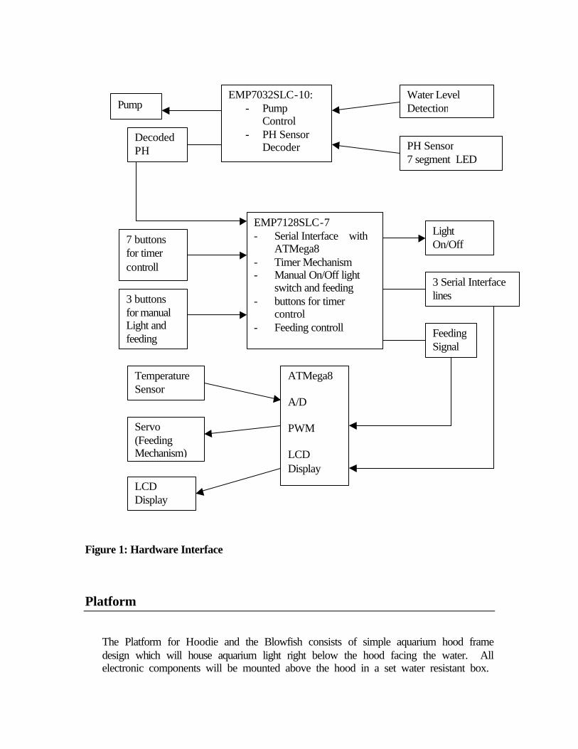
Figure 1: Hardware Interface
Platform
The Platform for Hoodie and the Blowfish consists of simple aquarium hood frame design which will house aquarium light right below the hood facing the water. All electronic components will be mounted above the hood in a set water resistant box.
ATMega8 A/D PWM LCD Display
Temperature Sensor
Servo (Feeding Mechanism)
EMP7032SLC-10: - Pump
Control - PH Sensor
Decoder
PH Sensor 7 segment LED
Water Level Detection Pump
Decoded PH
EMP7128SLC-7 - Serial Interface with ATMega8 - Timer Mechanism - Manual On/Off light switch and feeding - buttons for timer control - Feeding controll
7 buttons for timer controll
3 buttons for manual Light and feeding
3 Serial Interface lines
Light On/Off
Feeding Signal
LCD Display

Frame itself will be built using 1/8 inch thick balsa wood. Below is the picture of the platform with the fishtank:
Picture 1: Aquarium with Hoodie and the Blowfish Platform on top.
Actuation
Feeding Mechanism
The feeding mechanism will consist of flake (fish food) reservoir which will dispense a set amount of food. A “toothpick” dispensing design may be used. The flake reservoir would have a cylinder bellow it containing a carved out space for flakes. As cylinder rotates, a set amount of flakes will fall be dispensed to fall into the water beneath.

Figure 2 : Feeding Mechanism As displayed in Figure 2, the cylinder will be rotated 180 degrees using an un- hacked servo controlled by ATMega8.
Water Level Sensing The water level in the aquarium will be approximated using two wires and resistance between them. If both wires are in the water, the resistance between them would be much smaller than in air. Note Figure 3 below showing the circuit used for water level detection. Two Mega Ohm resistor was used to increase the voltage of Water Level Signal. With this set up the Water Level Signal had value of 4.7 to 4.9 volts when two wires were in the water, and 0 volts when two wires were in the air. The Water Level Signal was sent straight to CPLD to be used for pump controls.

Figure 3 : Water Level Detection Circuit
The actual pump control was set up in CPLD logic. Original set up contained two water level detection circuits in the main tank and one water level detection circuit in back up tank. This set up was later changed to only one water level detection circuit in main tank for simplicity purposes. See appendix for VHDL code for water level detection.
Timer Mechanism Timer mechanism is an essential part of Hoodie and the Blowfish, for it determines when the fish should be fed and when the lights should be turned on and off. The timer mechanism also allows user to set current time and to check when the fish were last fed. In all timer mechanism contains 7 control buttons:
- Timer Reset - Hour increment - Minute increment - Select Timer - Select Alarm - Set Timer or Alarm - Set Timer
To set the current time user would hold timer select button and increment hour and minute sections of time through hour increment and minute increment buttons. When desired time is set user latches the time in a register by pressing set timer or alarm button. To transfer the latched time to the actual clock set timer button is pressed. Alarm is set similarly as time, but here Select alarm button is pressed while adjusting time. Set Timer or Alarm button latches the alarm signal to alarm register. Whenever the alarm register and current time registers hold same value, a signal is sent to microcontroller to feed the fish and lights are turned on. Lights are automatically turned off at 23:00.

Timer also features a register for holding time of last feeding. This register has input from current time, which is latched using “feed” signal, thus when accessed, this register would contain the time when fish were fed. Note that only one signal is sent to serial interface from the timer mechanism. The selection between different times is set up through a mux to automatically select time register which is being altered and display it to LCD screen depending on which buttons are pressed. For example, when Select Alarm is pressed, mux selects alarm register and sends it to LCD screen so that user could view minutes and hours being incremented at real time. Timer mechanism also has three separate switches to control the feeding and light on/off signal. The “feed the fish” switch signal is passed through an or gate before it goes to a microcontroller so that microcontroller would receive the signal when switch is pressed or when signal is sent from timer mechanism to feed the fish. This way two signals would never collide and cause problems. Similarly switch is set up to turn on the light and to turn off the aquarium light.
Sensors
PH Sensor HI 98106 Champ PH sensor was interfaced with ATMega8 to measure the PH of the aquarium water. PH sensor has ICL7126 A/D converter which is interfaced directly to 7 segment LED display (See figure 4 below). To obtain the pH reading and display it on LCD where the rest of the information is shown, the pH had to be transferred to ATMega8. The simplest way to obtain the pH was to take the 7 segment LED signals from A/D on pH sensor and to decode them in the CPLD. Decoded pH values were then transferred through serial interface to the ATMega8 where the pH value was separated into two digits and outputted to LCD display. All of the code and decoding VHDL may be found in the appendix.

Figure 4: pH sensor A/D Pinout
Temperature Sensor LM34DZ temperature sensor was used for temperature detection. The temperature sensor chip was glued to the aquarium side to read the temperature of the water. Temperature sensor chip was configured to measure Fahrenheit temperature and for every degree it would output 0.01V thus it was interfaced directly to A/D converter on ATMega8 microcontroller and results were outputted to LCD screen.
Behaviors
The behaviors of Hoodie and the Blowfish include feeding the fish, adding more water if needed, turning aquarium light on and off, checking temperature of the water and checking pH of the water and displaying these values to LCD screen. The routine of Hoodie and the Blowfish includes to continually display current time. Every minute or so Hoodie and the Blowfish will check the temperature and pH of

the water and display these values on LCD screen. The timer mechanism continuously checks time and compares it against alarm register, when these two values are equal; the robot will turn on the aquarium light and will feed the fish. The aquarium light will be automatically turned off at 23:00. Hoodie and the Blowfish also continually checks the water level in the fish tank. When the water level in the fishtank falls below certain level, more water will be added given that there is enough water in the backup tank. Note that if there isn’t enough water in backup tank, the pump will never be turned on.
Conclusion
There is one major problem in Hoodie and the Blowfish actuation which restricts the demonstration of completely functional robot. The aquarium lights used for all aquariums are fluorescent lights, just like the one I have used. These lights require a starter which is a transformer to start up the light, without it, the light would not turn on. The transformer created the problem of creating massive spikes in the power lines that appeared to reset the cpld and microcontroller boards, thus whenever the light was turned on, the boards were reset. Attempted fix was to use optoisolators and set the power supplies for relays for the fluorescent light and water pump separately from microcontroller and CPLD’s. This solution did not seem to work since the spikes were transmitted through the power lines themselves. Another solution proposed was to use the 12 volt battery to power CPLD’s and microcontroller, this way no spikes could directly get to the microcontroller through the power lines. When this solution was implemented the board was still observed to reset but not as often as previously. When light was turned on, the board still reset most of the time, but now when light was turned off the boards would not reset most of the time. The oscilloscope was used again to view power and ground planes of microcontroller and spikes were still observed when light was turned on and off. The phenomena of the board resetting when light was turned on and off with the two devices having no common power supply or common ground connections was then attributed to electric or magnetic field. The proposed solution after this finding was to build a Faraday cage to enclose all electronics of Hoodie and the Blowfish in order to shield against electric field. Aluminum foil was used to wrap all electronic components of the robot and the foil was grounded to the battery powering the electronics of Hoodie and the Blowfish. This proposed solution did not appear to solve the problem, for the board was still resetting most of the time when light was turned on. The next solution proposed was now to eliminate fluorescent light from the design and replace it with alternative lighting containing no transformers. This solution has not been implemented as of yet but in theory should fix the problem. All individual components of Hoodie and the Blowfish work correctly, and even all interfaced components work correctly if light and water pump are eliminated and replaced with LED’s or different components containing no transformers.

Special Thanks to Uriel, Kevin, Greg, Brian, Louis, Carl, Will and Dr. Arroyo for their suggestions and support.
Documentation
Microcontroller: ATMega8 : Compliments of Uriel Rodriguez PH Sensor : Champ PH Meter Purchased from: http://www.aquamallusa.com/champhmet114.html Datasheet for sensor: http://www.hannainst.com/downloads/instr/hi98106.pdf A/D Datasheet: http://www.intersil.com/data/fn/fn3084.pdf Temperature Sensor: LM34DZ http://www.allelectronics.com/cgi-bin/category.cgi?category=search&item=LM34DZ&type=store CPLD’s: EMP7128SLC-7 : UP2 Board EMP7032SLC-10 3701 Board CPLD’s can be purchased at www.arrow.com Relays: www.jameco.com Water Pump: 30HP water fountain pump Lowes in Butler Plaza, Gainesville FlourescentAquarium Light Aquatropics on 34th street in Kash’nCarry plaza, Gainesville
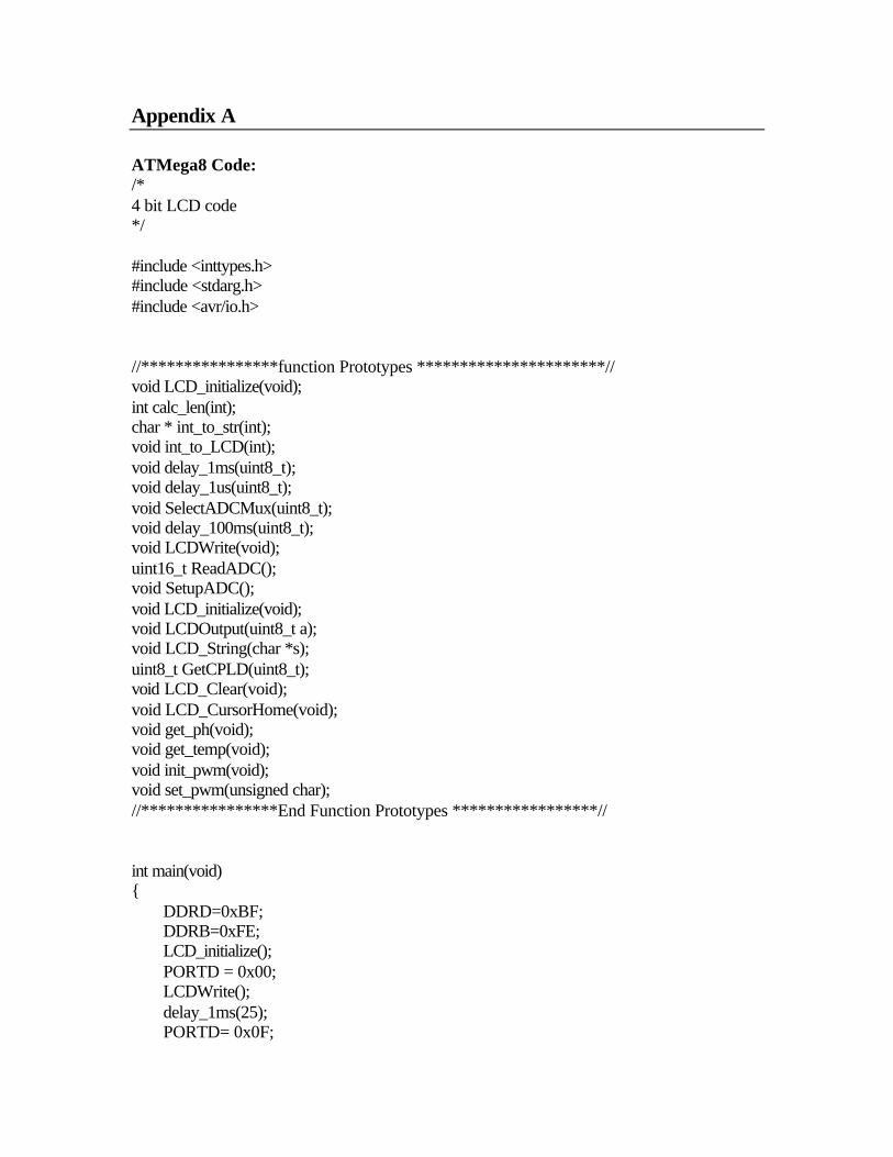
Appendix A ATMega8 Code: /* 4 bit LCD code */ #include <inttypes.h> #include <stdarg.h> #include <avr/io.h> //****************function Prototypes **********************// void LCD_initialize(void); int calc_len(int); char * int_to_str(int); void int_to_LCD(int); void delay_1ms(uint8_t); void delay_1us(uint8_t); void SelectADCMux(uint8_t); void delay_100ms(uint8_t); void LCDWrite(void); uint16_t ReadADC(); void SetupADC(); void LCD_initialize(void); void LCDOutput(uint8_t a); void LCD_String(char *s); uint8_t GetCPLD(uint8_t); void LCD_Clear(void); void LCD_CursorHome(void); void get_ph(void); void get_temp(void); void init_pwm(void); void set_pwm(unsigned char); //****************End Function Prototypes *****************// int main(void) { DDRD=0xBF; DDRB=0xFE; LCD_initialize(); PORTD = 0x00; LCDWrite(); delay_1ms(25); PORTD= 0x0F;

LCDWrite(); delay_1ms(25); init_pwm(); uint8_t servo; while(1) { get_ph(); delay_100ms(2); get_temp(); delay_100ms(2); uint8_t a, b; a=GetCPLD(2); b=GetCPLD(1); int_to_LCD(b); LCD_String(":"); int_to_LCD(a); delay_100ms(15); LCD_Clear(); LCD_CursorHome(); PORTD &=0xBF; servo = PIND; //int_to_LCD(servo); servo &= 0x40; int_to_LCD(servo); if (servo == 64) { feed_fish(); delay_100ms(20); } LCD_Clear(); LCD_CursorHome(); } return 0; } void feed_fish(void) { LCD_Clear(); LCD_CursorHome(); LCD_String("Feeding Fish"); init_pwm(); set_pwm(10); delay_100ms(18);
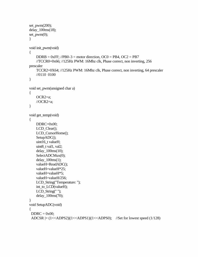
set_pwm(200); delay_100ms(18); set_pwm(0); } void init_pwm(void) { DDRB = 0xFF; //PB0-3 = motor direction, OC0 = PB4, OC2 = PB7 //TCCR0=0x66; //125Hz PWM: 16Mhz clk, Phase correct, non inverting, 256 prescaler TCCR2=0X64; //125Hz PWM: 16Mhz clk, Phase correct, non inverting, 64 prescaler //0110 0100 } void set_pwm(unsigned char a) { OCR2=a; //OCR2=a; } void get_temp(void) { DDRC=0x00; LCD_Clear(); LCD_CursorHome(); SetupADC(); uint16_t valueH; uint8_t val1, val2; delay_100ms(10); SelectADCMux(0); delay_100ms(1); valueH=ReadADC(); valueH=valueH*25; valueH=valueH*5; valueH=valueH/256; LCD_String("Temperature: "); int_to_LCD(valueH); LCD_String(" "); delay_100ms(70); } void SetupADC(void) { DDRC = 0x00; ADCSR |= (1<<ADPS2)|(1<<ADPS1)|(1<<ADPS0); //Set for lowest speed (1/128)

ADCSR |= (1<<ADFR); //Free running ADC ADMUX = 0x00; //Only reading channel 0 (right adjust) ADCSR |= (1<<ADEN); //Enable the ACD itself ADCSR |= (1<<ADSC); //And start the first conversion //ADCSR |= (1<<ADIE); //And enable interrupts (when complete) } uint16_t ReadADC(void) { uint16_t value; //value is only 10 bit though. value = ADCL; value += (ADCH & 0x03)<<8; return value; } void SelectADCMux(uint8_t i) { if (i == 0) ADMUX &=0xF0; else if (i == 1) { ADMUX &=0xF0; ADMUX |=0x01; } else if (i == 2) { ADMUX &=0xF0; ADMUX |=0x02; } else if (i == 3) { ADMUX &=0xF0; ADMUX |=0x03;

} else if (i == 4) { ADMUX &=0xF0; ADMUX |=0x04; } else if (i == 5) { ADMUX &=0xF0; ADMUX |=0x05; } else if (i == 6) { ADMUX &=0xF0; ADMUX |=0x06; } else { ADMUX &=0xF0; ADMUX |=0x07; } } void get_ph(void) { uint8_t value1, value2, value0; LCD_Clear(); LCD_CursorHome(); LCDOutput(0x50); delay_1ms(50); LCDOutput(0x48); delay_1ms(50); LCDOutput(0x20); value0=GetCPLD(0); value1=value0 & 0xF0; value1=value1>>4; value2=value0 & 0x0F; value1 = 0x30+value1; value2 = 0x30 + value2; LCDOutput(value2); delay_1ms(10); LCDOutput(0x2E); delay_1ms(10); LCDOutput(value1); delay_100ms(70);
} void delay_100ms(uint8_t a) { uint8_t i; for ( i=0; i<a; i++) { delay_1ms(100); } } void LCD_String(char *s) { while (*s) LCDOutput(*s++); } void LCD_Clear(void) { PORTD = 0x00; LCDWrite(); delay_1ms(50); PORTD= 0x01; LCDWrite(); delay_1ms(50); } void LCD_CursorHome(void) { PORTD = 0x00; LCDWrite(); delay_1ms(50); PORTD= 0x02; LCDWrite(); delay_1ms(50); } void LCDOutput(uint8_t a) { delay_1ms(50); uint8_t temp=a; a >>=4; //send first nibble to port D a |= 0x20; PORTD = a; LCDWrite(); delay_1ms(50);
temp &=0x0F; temp |=0x20; PORTD= temp; LCDWrite(); delay_1ms(50); } uint8_t GetCPLD(uint8_t x) { //PB2 = Enable latch //PB1=clock //PB0=data //PB4 =S0 //pb5 =s1 DDRB &=0xFE; //b7, b6 b3-> leave alone ; b5, b4, b2, b1 -> output ; b0 -> input DDRB |=0x36; //set which data to receive uint8_t ser, i, a; if (x== 0) //receive ph { PORTB &=0xCF; PORTB |=0x0E; } else if (x==1) //receive hours { PORTB &=0xCF; PORTB |=0x10; } else if(x==2) //receive minutes { PORTB &=0xCF; PORTB |=0x20; } else { PORTB &=0xCF; //by default set to ph PORTB |=0x0E; } ser=0; PORTB |=0x04; //set pb2 PORTB &=0xFD; //set clock low

PORTB |=0x02; //set clock hi PORTB &=0xFB; //clear pb2 PORTB &=0xFD; PORTB |=0x02; for ( i=0; i<7; i++) { PORTB &=0xFD; //set clock low a=PINB; a &=0x01; ser=ser+a; //read port PB0 and shift it into data register ser=(ser<<1); PORTB |=0x02; //set clock hi } PORTB &=0xFD; //set clock low a=PINB; a &=0x01; ser=ser+a; //read port PB0 and shift it into data register PORTB |=0x02; //set Clock Low return ser; } void delay_1us(uint8_t i) //method which waits i us. { uint8_t j; while ( i ) { for (j=0 ; j<4 ; j++ ); i--; } } void LCDWrite(void) { PORTD = (PORTD | 0x80); //Set LCD enable low delay_1us(2); PORTD = (PORTD & 0x7F); //set LCD enable high } void delay_1ms(uint8_t i) //method which waits i ms. { uint8_t j, k; while ( i ) {

for (j=0 ; j<200 ; j++ ) { for ( k=0 ; k < 2; k++); } i--; } } void LCD_initialize(void) { /*****************************Hardware Set up information for LCD************************* PA7 = Enable on LCD PIN 6 on LCD PA6 = Not connected PA5 = RS signal Pin4 on LCD PA4 = RW pin5 on LCD PA3 .. PA0 = LCD7..4 /*****************************End of LCD Hardware Set up Info ****************************/ delay_1ms(17); //wait at least 15ms on power on PORTD= 0x03; //RS R/W DB7 DB6 DB5 DB4 DB3 DB2 DB1 DB0 LCDWrite(); //0 0 0 0 1 1 x x x x x=don't care, set E low to write delay_1ms(6); //RS R/W DB7 DB6 DB5 DB4 DB3 DB2 DB1 DB0 PORTD = 0x03; //0 0 0 0 1 1 x x x x LCDWrite(); delay_1us(150); //RS R/W DB7 DB6 DB5 DB4 DB3 DB2 DB1 DB0 PORTD = 0x03; //0 0 0 0 1 1 x x x x LCDWrite(); delay_1ms(6); //RS R/W DB7 DB6 DB5 DB4 DB3 DB2 DB1 DB0 PORTD = 0x02; //0 0 0 0 1 0 x x x x LCDWrite(); delay_1us(60); //<Wait 4.1ms> PORTD = 0x02; //RS R/W DB7 DB6 DB5 DB4 DB3 DB2 DB1 DB0 LCDWrite(); //0 0 0 0 1 0 N F x x delay_1us(60); //4-bit operation //N=Number of `lines' PORTD = 0x08; //0 for 1/8 duty cycle -- 1 `line' LCDWrite(); //1 for 1/16 duty cycle -- 2 `lines'

delay_1us(60); //F=font, //1 for 5x11 dot matrix //0 for 5x8 dot matrix delay_1us(80); //<Wait 40us or till BF=0> PORTD = 0x00; //RS R/W DB7 DB6 DB5 DB4 LCDWrite(); //0 0 0 0 0 0 delay_1us(70); //0 0 1 0 0 0 PORTD = 0x08; //display off, cursor off, blink off LCDWrite(); delay_1us(50); delay_1us(70); //<Wait 40us or till BF=0> PORTD = 0x00; //RS R/W DB7 DB6 DB5 DB4 LCDWrite(); //0 0 0 0 0 0 delay_1us(70); //0 0 0 0 0 1 PORTD = 0x01; //Clear screen, cursor home LCDWrite(); delay_1us(60); delay_1ms(4); //<Wait 40us or till BF=0> PORTD = 0x00; //RS R/W DB7 DB6 DB5 DB4 LCDWrite(); //0 0 0 0 0 0 delay_1us(70); //0 0 0 1 1 0 PORTD = 0x06; //increment cursor to theright when writing, dont shift screen LCDWrite(); delay_1us(50); //initialization complete } char * int_to_str(int val) { int len = calc_len(val); char str[len+1]; int i; for (i = len - 1; i >= 0; i--) { str[i] = val%10 + 0x30; //converts digit to ASCII equivalent by adding 0x30 val /= 10; } str[len] = '\0'; return(str); }
void int_to_LCD(int val) { int len = calc_len(val); char str[len+1]; int i; for (i = len - 1; i >= 0; i--) { str[i] = val%10 + 0x30; //converts digit to ASCII equivalent by adding 0x30 val /= 10; } str[len] = '\0'; for( i=0 ; i< len; i++) { LCDOutput(str[i]); } } int calc_len(int val) //calculates length of integer...cannot be greater than 5 digits (16bit int) { int done=0; int length=1; while(!done) { if(val>10) { length++; val=val/10; } else { done=1; } } return(length); }

Appendix B Pump and PH decoder in EMP7032SLC-10 CPLD:
VHDL Code :

PHSensor: library ieee; use ieee.std_logic_1164.all; USE IEEE.STD_LOGIC_ARITH.ALL; entity PHsensor is port( a1, a2 : in STD_LOGIC_VECTOR(6 downto 0); bp : in STD_LOGIC; q : out std_logic_vector(7 downto 0) ); END PHsensor; ARCHITECTURE behavior of PHsensor IS Signal b, z1, z2 : STD_LOGIC_VECTOR(6 downto 0); Signal m1, m2 : STD_LOGIC_VECTOR(3 downto 0); BEGIN latch1 : process(bp) begin if(bp'event and bp='1') then b <= bp & bp & bp & bp & bp & bp & bp; z1 <=( a1 xor b) ; z2 <=( a2 xor b) ; end if; end process; WITH z1 SELECT m1 <= "0000" when "1111110", "0001" when "0110000", "0010" when "1101101", "0011" when "1111001", "0100" when "0110011", "0101" when "1011011", "0110" when "1011111", "0111" when "1110000", "1000" when "1111111", "1001" when "1111011", "1111" when others; WITH z2 SELECT m2 <= "0000" when "1111110", "0001" when "0110000", "0010" when "1101101", "0011" when "1111001", "0100" when "0110011", "0101" when "1011011",

"0110" when "1011111", "0111" when "1110000", "1000" when "1111111", "1001" when "1111011", "1111" when others; lat: process(bp) begin if (bp'event and bp='1') then q <= m1 & m2; end if; end process; END behavior; PumpControl: library ieee; use ieee.std_logic_1164.all; entity pumpControl is port( tank1, tank2, r : in std_logic; pumpOn : out std_logic); end pumpControl; ARCHITECTURE behavior of pumpControl IS signal temp : std_logic; BEGIN pumpOn <= not tank1 and r; END behavior; EMP7128SLC CPLD GDF Diagram:

Clock Device VHDL: library ieee; use ieee.std_logic_1164.all; use ieee.std_logic_unsigned.all; entity clockingdev is port ( clk : in std_logic; m : in std_logic; minute : in std_logic_vector(5 downto 0); hour : in std_logic_vector(4 downto 0); Qminut : out std_logic_vector(5 downto 0); Qhr : out std_logic_vector(4 downto 0); sec : out std_logic_vector(1 downto 0);

secClk : out std_logic; rst : in std_logic); end clockingdev; architecture behavior of clockingdev is signal Asec : std_logic_vector(10 downto 0); signal Amin : std_logic_vector(5 downto 0); signal A : std_logic_vector(4 downto 0); signal Csec : std_logic; signal Cmin : std_logic; begin mySecond : process(clk, rst) begin if (clk'event and clk='1') then if rst = '1' then Asec <= "00000000001"; Csec <='0'; elsif Asec = "11000001010" then Asec <= "00000000001"; Csec<='1'; else Asec <= Asec + 1; Csec <='0'; end if; end if; secClk <=Asec(5); sec <= Asec(10) & Asec(9); end process mySecond; myMinutes : process(Csec, rst) begin if rst='1' then Amin<="000000"; cmin <='0'; elsif ( m = '1') then Amin <= minute; elsif (Csec'event and Csec='1') then if Amin = "111011" then Amin <= "000000"; cmin <= '1'; else Amin <= Amin + 1; cmin <= '0'; end if; end if;

Qminut <= Amin; end process myMinutes; myHour : process(cmin) begin if rst='1' then A <= "00000"; elsif (m='1') then A <= hour; elsif (cmin'event and cmin='1') then if A = "10111" then A <= "00000"; else A <= A + 1; end if; end if; end process myHour; Qhr <= A; end behavior; Latching Time VHDL: library ieee; use ieee.std_logic_1164.all; use ieee.std_logic_unsigned.all; entity latchtime is port( alarm1 : in std_logic; timer : in std_logic; setTime1 : in std_logic; minCntA : in std_logic_vector(5 downto 0); hrCntA : in std_logic_vector(4 downto 0); minCntT : in std_logic_vector(5 downto 0); hrCntT : in std_logic_vector(4 downto 0); minOutA : out std_logic_vector(5 downto 0); hrOutA : out std_logic_vector(4 downto 0); minOutT : out std_logic_vector(5 downto 0); hrOutT : out std_logic_vector(4 downto 0)); end latchtime; architecture behavior of latchtime is begin setT :process(setTime1) begin

if(setTime1'event and setTime1 = '1') then if (alarm1 = '1') then minOutA <= minCntA; hrOutA <= hrCntA; elsif (timer = '1') then minOutT <= minCntT; hrOutT <= hrCntT; end if; end if; end process setT; end behavior; Loading Time into Timer VHDL: library ieee; use ieee.std_logic_1164.all; use ieee.std_logic_unsigned.all; entity minuteLoad is port( alarm : in std_logic; clk : in std_logic; timer : in std_logic; minute1 : in std_logic; hour1 : in std_logic; mintimA : out std_logic_vector(5 downto 0); hrtimA : out std_logic_vector(4 downto 0); mintimT : out std_logic_vector(5 downto 0); hrtimT : out std_logic_vector(4 downto 0)); end minuteLoad; architecture behavior of minuteLoad is Signal minCntA : std_logic_vector(5 downto 0); Signal hrCntA : std_logic_vector(4 downto 0); Signal minCntT : std_logic_vector(5 downto 0); Signal hrCntT : std_logic_vector(4 downto 0); signal temp2 : std_logic_vector(1 downto 0); signal temp3 : std_logic_vector(1 downto 0); Signal minute : std_logic; signal hour : std_logic; begin debounceminute : process(clk) begin
if (clk'event and clk= '1') then temp2(1) <= temp2(0); temp2(0) <= minute1; end if; minute <= minute1 and temp2(0) and temp2(1); end process debounceminute; debouncehour : process(clk) begin if (clk'event and clk= '1') then temp3(1) <= temp3(0); temp3(0) <= hour1; end if; hour <= hour1 and temp3(0) and temp3(1); end process; min3 : process(minute) begin if (minute'event and minute='1') then if (alarm = '1') then if (minCntA = "111011") then minCntA <= "000000"; else minCntA <= minCntA + 1; end if; end if; end if; end process min3; hr3 : process(hour) begin if (hour'event and hour='1') then if (alarm = '1') then if (hrCntA = "10111") then hrCntA <= "00000"; else hrCntA <= hrCntA + 1; end if; end if; end if; end process hr3; minT : process(minute) begin if (minute'event and minute='1') then if (timer = '1') then

if (minCntT = "111011") then minCntT <= "000000"; else minCntT <= minCntT + 1; end if; end if; end if; end process minT; hrT : process(hour) begin if (hour'event and hour='1') then if (timer = '1') then if (hrCntT = "10111") then hrCntT <= "00000"; else hrCntT <= hrCntT + 1; end if; end if; end if; end process hrT; mintimA <= minCntA; hrtimA <= hrCntA; mintimT <= minCntT; hrtimT <= hrCntT; end behavior; Feeder Controll: library ieee; use ieee.std_logic_1164.all; use ieee.std_logic_unsigned.all; entity feederControl is port( minAlarm : in std_logic_vector(5 downto 0); hrAlarm : in std_logic_vector(4 downto 0); minTime : in std_logic_vector(5 downto 0); hrTime : in std_logic_vector(4 downto 0); mysec : in std_logic_vector(1 downto 0); feednow : in std_logic; lgh : in std_logic; liteoff : in std_logic; clk : in std_logic; feed : out std_logic; lightOn : out std_logic

); end feederControl; architecture behavior of feederControl is Signal hrAlarmL : std_logic_vector(4 downto 0); Signal minAlarmL : std_logic_vector(5 downto 0); Signal tmp : std_logic; begin fd : process(clk) begin if (clk'event and clk='1') then if (((hrTime = hrAlarm) and (minTime = minAlarm)) and ((mysec = "11") or (mysec="10"))) then feed <= '1'; lightOn <='1'; elsif (feednow = '1') then feed <='1'; elsif (liteoff='1') then lightOn <='0'; elsif (lgh = '1') then lightOn <= '1'; elsif (((hrTime = "10111") and (minTime = "000000"))) then lightOn <='0'; else feed <= '0'; end if; end if; end process fd; end behavior; Muxes for Minutes and Hours: library ieee; use ieee.std_logic_1164.all; entity VilijaMux35 is port( a3, a2, a1, a0 : in STD_LOGIC_VECTOR(5 downto 0); s : in STD_LOGIC_vector(1 downto 0); Z1 : out STD_LOGIC_VECTOR(5 downto 0)

); END VilijaMux35; ARCHITECTURE behavior of VilijaMux35 IS BEGIN WITH s SELECT Z1 <= a3 when "11", a2 when "10", a1 when "00", a0 when "01", a1 when others; END behavior; library ieee; use ieee.std_logic_1164.all; entity VilijaMux34 is port( a3, a2, a1, a0 : in STD_LOGIC_VECTOR(4 downto 0); s : in STD_LOGIC_vector(1 downto 0); Z1 : out STD_LOGIC_VECTOR(4 downto 0) ); END VilijaMux34; ARCHITECTURE behavior of VilijaMux34 IS BEGIN WITH s SELECT Z1 <= a3 when "11", a2 when "10", a1 when "00", a0 when "01", a1 when others; END behavior; Code to display when fish were last fed : library ieee; use ieee.std_logic_1164.all;

use ieee.std_logic_unsigned.all; Entity inquiry is port ( clk : in std_logic; feednow : in std_logic; minFed : in std_logic_vector(5 downto 0); hrFed : in std_logic_vector(4 downto 0); mint : out std_logic_vector(5 downto 0); hour : out std_logic_vector(4 downto 0)); end inquiry; architecture behavior of inquiry is begin process(clk) begin if (clk'event and clk='1') then if (feednow = '1') then mint <= minFed; hour <= hrFed; end if; end if; end process; end behavior; Mux to select appropriate time: library ieee; use ieee.std_logic_1164.all; entity VilijaMux2 is port( a2, a1, a0 : in STD_LOGIC_VECTOR(7 downto 0); s : in STD_LOGIC_Vector(1 downto 0); z1 : out STD_LOGIC_VECTOR(7 downto 0) ); END VilijaMux2; ARCHITECTURE behavior of VilijaMux2 IS BEGIN WITH s SELECT

Z1 <= a0 when "11", a2 when "10", a1 when "01", a0 when "00", a0 when others; END behavior; Serial Interface : library ieee; use ieee.std_logic_1164.all; entity shiftRegister is port( shiftclk: in std_logic; en : in std_logic; d: in std_logic_vector(7 downto 0); q: out std_logic); end shiftRegister; architecture archregistered of shiftRegister is signal temp : std_logic_vector(7 downto 0); begin reg: process (shiftclk) begin if (shiftclk'event and shiftclk= '1') then if (en = '1') then temp<=d; else q <= temp(7); temp(7) <= temp(6); temp(6) <= temp(5); temp(5) <= temp(4); temp(4) <= temp(3); temp(3) <= temp(2); temp(2) <= temp(1); temp(1) <= temp(0); end if; end if; end process reg;

end archregistered;