Wright 2600
78
-
Upload
tim-matlack -
Category
Documents
-
view
132 -
download
6
Transcript of Wright 2600
5/11/2018 Wright 2600 - slidepdf.com
http://slidepdf.com/reader/full/wright-2600 1/77
•
RESTRICTED AN 02-35HC-2
Handbook of
Service Instructions
for
AIRCRAFT ENGINES
Models
R-2600-20 and -22
NOTE: THIS PUBLICATION SUPERSEDES AN 02-35HC-2
DATED 2.5 FEBRUARY 1944
PUBLISHED UNDER JOINT AUTHORITY OF THE COMMANDING GENERAL,
ARMY AIR FORCES, THE CHIEF OF THE BUREAU OF AERONAUTICS,AND THE AIR COUNCIL OF THE UNITED KINGDOM
NOTlCE.-This document contains information affecting the national de-fense of the United States within the meaning of the Espionage Act, 50U. S. -C., 31 and 32, as amended. Its transmission or the r~ve/ation ofits contents in any manner to an unauthorized person is prohibited by law.
15 August 1945
5/11/2018 Wright 2600 - slidepdf.com
http://slidepdf.com/reader/full/wright-2600 2/77
•
- ,
-.
\ r - - - - - - - - - - - - - - - - - - - ~ - - - - - - ~ - - - - - - - ~ ' ~ - - - - - - - - - - - - - - - - - - - - - - - - - - - - - - ~RESTRICTED AN 02-35HC-2
Handbook of
Service .Instructions
for
AIRCRAFT ENGINES
Models
R-2600-20 and -22
NOTE: THIS PUBLICATION SUPERSEDES AN 02-35HC-2
DATED 25 FEBRUARY 1944
PUBLISHED UNDER JOINT AUTHORITY OF THE COMMANDING GEtclERAL,
ARMY AIR FORCES, THE CHIEF OF THE BUREAU OF AERONAUTICS,
AND THE AIR COUNCIL OF THE UNITED KINGDOM
NOTlCE.-This document contains information affecting the national de-fense of the United States within the meaning of the Espionage Act, 50U.. s. -C,; 31 and 32, as amended. Its transmission or the r~ve/ation ofits contents in any manner to an unauthorized person is prohibited by law.
5/11/2018 Wright 2600 - slidepdf.com
http://slidepdf.com/reader/full/wright-2600 3/77
RESTRICTED
AN 02-3SHC-2
Published under joint authority of the Commanding General, Army Air
Forces, the Chief of the Bureau of Aeronautics, and the Air Council of
the United Kingdom.
1 1 · H I S P U B L I C A T I O N M A Y B E U S E D B Y P E R S O N N E L R E N D E R I N G S E R V I C E T O T H E U N I T E D S T A T E S O R I T S A L L I E S
I.jPara~taph S.d. 01 Army Regulation 380-5 relative co the handling 01
~"restricted" printed matter is quoted below.
in Government u'ork, but will not be communicated to [he public or to (he
press except by authorized milieary public rel arions agencies."
"d. Dissemination of restricted mane-c.-The information contained in
r e s r r i c r e d documents and the e s s e n t i a l characteristics of restricted r na r e r i a l
may be given (0any person know" 10 be in the s ervic e oj tbe United St a t es
and 10 persons 0/ undoubted loyally and discretion who art cooperating
This permits (he is sue of "restricted" publ ications [0civitian contra" and
other accredited schools engaged in training personnel for Government
work. [0 civrlian concerns contracting for overhaul and repair of aircraft
Or a ircra ft accessories, and [0 similar commercial organizations.
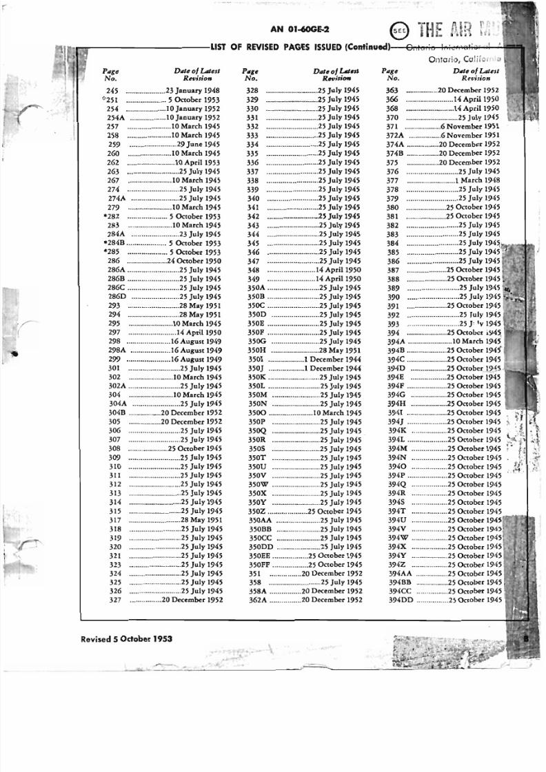
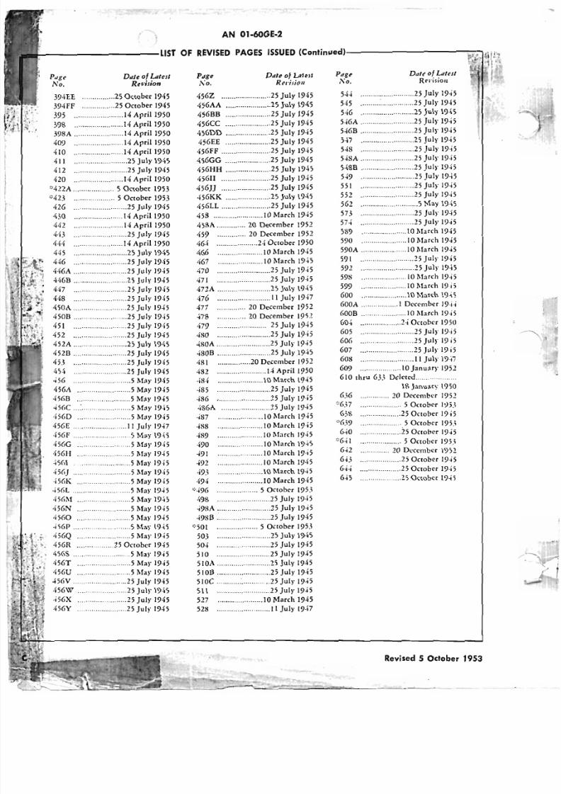
r---"-'------------LST OF REVISED PAGES ISSUED-------- ----.
NOTE: A heavy black vertical line, 10 the left of the text on revised pages, indicates the
extent of the revision. This line is omitted where more than 50 percent of the page is revised.
Special Dislri~ution__:2500-Naval Aviation Supply Depot, Publication Division, A-384, G.P.O.
Box 865~, Pblladelphl~ I, ~a.--:-900~Bureau of Aeronautics, Resident Representative, WrightAeronautical Corporation Cincinnati Plant, Lockland Station, Cincinnati, Ohio.
ADDITIONAL COPIES OF THIS PUBLICATION MAY BE OBTAINED AS FOLLOWS:
'6,!-F :"-C~IVITIES.-~ubmie requisiei<:>cs co the Comm~nding General, Fairfield Air Service Command. Parrerson Field. Fairfield. Ohio. Aneneion': Publicaeionsisrriburioe Branch. Inaccordance with AAF Regularion No. 5-9. Also, lor derails 01 Technical Order diseribueion, see T. O. No. 00.25.3.
NAVY ACTIVITIES.-Submie requests co the Chief, Bureau 01 Aeronaueics, Navy Department. Washin~coD, D. C.
BRITISH ACTIVITIES.-Submie requirements on Form 294A, in duplicate, CO the Air Publicacions and Forms Score. New Cof lege Leadhall Lane Harro-gaee, Yorkshire, Enaland. . .
A RESTRICTED
5/11/2018 Wright 2600 - slidepdf.com
http://slidepdf.com/reader/full/wright-2600 4/77
Page
No.Page
No.
AN 01-6OGE-2
r--rr---------LlST OFREVISEDAGESSSUEDContillu8ld)-~~~"""""'~~~"""'''
·r(
Page
No.Dille 0/ LIIIesl
Revision
328 _ 25 July 1945
329 25 July 1945
330 25 July 1945
331 25 July 1945
332 25 July 1945
333 25 July 1945
334 25 July 1945
335 25 July 1945
336 25 July 1945
337 25 July 1945
338 25 July 1945
339 25 July 1945
340 25 July 1945
341 25 July 1945
342 25 July 1945
343 25 July 1945
344 25 July 1945
345 25 July 1945
346 25 July 1945
347 25 July 1945348 14 April 1950
349 14 April 1950
350A 25 July 1945
350B 25 July 1945
350C 25 July 1945
350D 25 July 1945
350E 25 July 1945
350F 25 July 1945
350G 25 July 1945
350H 28 May 1951
3501 1 December 1944
350J 1 December 1944
350K 25 July 1945
350L 25 July 1945
350M 25 July 1945350N 25 July 1945
3500 10 March 1945
350P 25 July 1945
350Q 25 July 1945
350R 25 July 1945
3505 25 July 1945
350T 25 July 1945
350U 25 July 1945
350V 25 July 1945
350W 25 July 1945
350X 25 July 1945
350Y 25 July 1945
350Z 25 October 1945
350AA 25 July 1945
350BB 25 July 1945350CC 25 July 1945
350DD 25 July 1945
350EE 25 October 1945
350FF 25 October 1945
351 20 December 1952
358 25 July 1945
358A 20 December 1952
362A 20 December 1952
Ontario, Caiirorrtio
Dille 0/ LIIIeslRevision
363 _ 20 December 1952
366 14 April 1950
368 ._ _ 14 April 1950
370 25 July 1945
371 6 November 1951
372A 6 November 1951
374A 20 December 1952
374B 20 December 1952
375 20 December 1952
376 25 July 1945
377 1March 1948
378 25 July 1945
379 25 July 1945
380 25 October 1945
381 25 October 1945
382 25 July 1945
383 25 July 1945
384 25 July 1 9 4 : J , ,
385 25 July
386 25 July 1945387 25 October 1945
388 25 October 1945
389 _.25 July 1945
390 25 July 1945
391 25 October 1945
392 25 July 1945
393 25 J 'v 1945
394 25 October i945
394A 10 March 1945
394B 25 October 1945
394C 25 October 1945
3940 25 October.l2~~
394E 25 October 1945
394F 25 October 1945
394G 25 October 1945394H 25 October 1945
3941 25 October 1945
394J 25 October 1945
394K 25 October 1945
394L 25 October 1945
394M 25 October 1945
394N 25 October 1945
3940 25 October 1945
394P 25 October 1945
394Q 25 October 1945
394R 25 October 1945
3945 25 October 1945
394T 25 October 1945394U
394V 25 October394W 25 October 194
394X 25 October 1945
394Y 25 October 1945
394Z 25 October 1945
394AA 25 October 1945
394BB 25 October 1945
394CC 25 October 1945
394DD 25 October 194
245 23 January 1948
*251 5 October 1953
254 10 January 1952
254A 10 January 1952
257 10 March 1945
258 10 March 1945
259 29 June 1945
260 10 March 1945
262 10 April 1953
263 25 July 1945
267 10 March 1945
274 25 July 1945
274A 25 July 1945
279 10 March 1945
*282 5 October 1953
283 10 March 1945
284A 23 July 1945
*284B 5 October 1953
*285 5 October 1953
286 24 October 1950286A 25 July 1945
286B 25 July 1945
286C 25 July 1945
286D 25 July 1945
293 28 May 1951
294 28 May 1951
295 10 March 1945
297 14 April 1950
298 16 August 1949
298A 16 August 1949
299 16 August 1949
301 25 July 1945
302 10 March 1945
302A 25 July 1945
304 10 March 1945304A 25 July 1945
304B _..20 December 1952
305 20 December 1952
306 25 July 1945
307 25 July 1945
308 25 October 1945
309 25 July 1945
310 25 July 1945
311 25 July 1945
312 25 July 1945
313 25 July 1945
314 25 July 1945
315 25 July 1945
317 28 May 1951
318 25 July 1945319 25 July 1945
320 25 July 1945
321 25 July 1945
323 25 July 1945
324 25 July 1945
325 25 July 1945
326 25 July 1945
327 20 December 1952
Revised 5 Odober 1953
5/11/2018 Wright 2600 - slidepdf.com
http://slidepdf.com/reader/full/wright-2600 5/77
-,... --AN01·60GE·2
':-----------LlST OFREVISEDAGESSSUEDContinued)------------.
PageNo.
Dale 0/ LatestRevision
394EE 25 October 1945
394fF 25 October 1945
395 14 Apri11950
398 14 April 1950
398A 14 April 1950409 14ApriI1950
410 14 April1950
411 25 July 1945
412 25 July 1945
420 14ApriI1950
"422A 5 October 1953
"423 5 October 1953
426 25 July 1945
430 14 April 1950
442 14 April 1950
4·13 25 July 1945
444 14 April 1950
445 25 July 1945
446 25 July 1945
446A 25 July 1945446B 25 July 19-i5
447 25 July 1945
448 25 July 1945
450A 25 July 1945
4508 25 July 1945
451 25 July 1945
452 25 July 1945
452A 25 July 1945
452B 25 July 1945
4B 25 July 1945
454 25 July 1945
456 5 May 1945
456A 5 May 1945
45(,B 5 May 1945
<i5GC .; May 1945
'I5(}D 5 May 1945
456E IIJulyI947
4;GF .......................5 l\fay 1945
456G .....................5 May 19·,5
1t56H 5 May 1945
·dGI 5 May 19,5
456J 5 May 1945
·i56K 5 May 19,5
456L 5 May 1945
4%M 5 May 1945
'i56N 5 May 1945
4560 5 May 1945
4S6P 5 May 1945
456Q 5 May 1945456R 25 October 1945
4565 5 May 1945
456T 5 May 1945
456U 5 May 1945
4;6V 25 July 1945
456W 25 July 1945
456X......... 25 July 1945
456Y 25 July 1945
Page
, " 0 .Dale 0/ Latest
Revision
Page,'\0.
Dale of LatestRecision
456Z 25 July 1945
456AA 25 July 1945
45GBB 25 July 1945
45GCC 25 July 1945
456DD 25 July 1945456EE 25 July 1945
45GFF 25 July 1945
4SGGG 25 July 1945
456HH 25 July 1945
456II 25 July 1945
45GJj 25 July 1945
45GKK 25 July 1945
45GLL 25 July 1945
458 10 March 1945
458A 20 December 1952
4S9 20 December 1952
464 2-i OCtober 1950
46G 10 March 19·,5
467 10 March 1945
470 25 July 1945471 25 July 1945
472A 25 July 1945
476 11 July 1947
477 20 December 1952
478 20 December 19;.!
479 25 July 1945
480 25 July 1945
.j80A 25 July 1945
480B 25 July 19-i5
.lSI 20 December 1952
482 14 April 1950
484 10 March 1945
485 25 July 1945
486 , , 25 July 19;5
486A 25 July 1945
487 IOMarch 1945
488 10 March 19·,5
-iS9 10 March 1945
490 10 March 19·;5
491 10 March 19·.5
-i92 10 March 1945
.j9.'1 10 March 1945
494 10 March 1945
';'496 5 October 195.,
498 25 July 19·,5
498A 25 July 1945
498B ~ 25 July 1945
"501 5 October 19B
503 25 July 1945504 25 July 1945
510 25 July 1945
SIOA 25 July 1945
5 lOB 25 July 1945
510e 25 July 19-!5
511 25 July 1945
527 10 March 1945
528 II July 19·,7
544 25 July 1945
545 ~ 25 July 1945
546 25 July 1945
5·iGA 25 July 1945
546B 25 July 1945547 25 July 1945
548 25 July 19';5
54SA 25 July 1945
548B 25 July 1945
549 25 July 1945
551 25 July 19-!5
552 25 July 1945
562 5 May 1945
573 25 July 1945
574 25 July 1945
589 10 March 1945
590 10 March 1945
590A 10 March 1945
591 25 July 1945
592 25 July 19-15598 10 March 1945
599 10 March 19i5
GOO I0 March 19-i5
600A 1 December 19·i·j
('OOB I0 March I9·i5
G04 24 October 1950
605 25 July 19i5
G06 25 July 19i5
607 25 July 19i5
608 11 July 19i7
609 10 January 1952
610 thru 635 Deleted ..
6.,6
'"6.,76.'S':'639
6';0
'~6-!1
642
6-!3
644
6·i5
IS January 1950
.... ... .. .. .. . 20 December 1952
.................... 5 October 1~5.\.................... 25 October 19i5
. .. .. .. .. .. .. .. .. .. . 5 October 195. '1
. . .. . .. . .. .. . .. . .. . . 2 5 October 19·;;
. .. ... .. .. .. .. .. .. . 5 October 195.,
.. .. ... .. .. .. . 20 December 1952
.................... 25 October 1945
.................... 25 October 19·;;
.................. 25 October 1945
RevisedOctober953
5/11/2018 Wright 2600 - slidepdf.com
http://slidepdf.com/reader/full/wright-2600 6/77
RESTRICTED
AN 02·35HC·2
Section Section
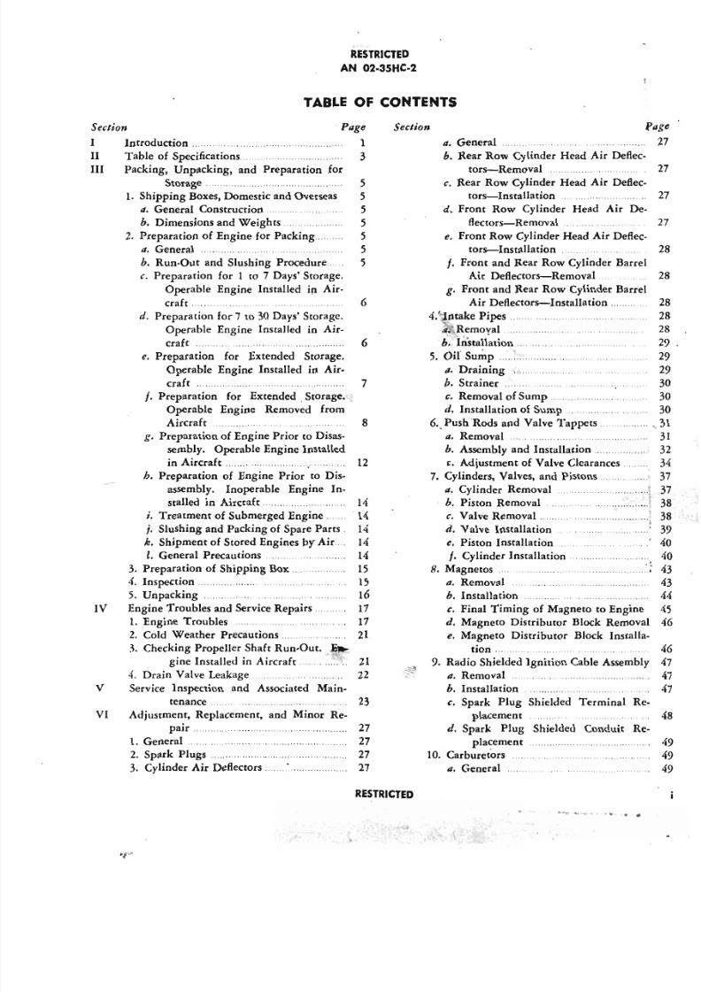
TABLE OF CONTENTS
I
Page
1
3
Introduction ..
Table of Specifications
Packing, Unpacking, and Preparation for
Storage .
1. Shipping Boxes, Domestic and Overseas
4. General Construction
b. Dimensions and Weights ..
2. Preparation of Engine for Packing ..
4. General
b. Run-Out and Slushing Procedure.
c. Preparation for 1 to 7 Days' Storage.
Operable Engine Installed in Air-
craft.
d. Preparation for 7 to 30 Days' Storage.
Operable Engine Installed in Air-craft . " .
e. Preparation for Extended Storage.
Operable Engine Installed in Air-
craft ..
f. Preparation for Extended. Storage.
Operable Engine Removed from
Aircraft 8
g. Preparation of Engine Prior to Disas-
sembly. Operable Engine Installed
in Aircraft. 12
h. Preparation of Engine Prior to Dis-
assembly. Inoperable Engine In-
stalled in Aircraft 14
I. Treatment of Submerged Engine.. . 14
j. Slushing and Packing of Spare Parts. 14
k. Shipment of Stored Engines by Air 14
I. General Precautions 14
3. Preparation of Shipping Box .. . 15
4. Inspection. . ..... ""'" 15
5. Unpacking 16
IV Engine Troubles and Service Repairs. 17
1. Engine Troubles 17
2. Cold Weather Precautions.. 21
3. Checking Propeller Shaft Run-Out. ~
gine Installed in Aircraft. .. . . ....... 214. Drain Valve Leakage. 22
V Service Inspection and Associated Main-
II
III
5
5
5
5
5
5
5
6
6
7
VI
tenance.
Adjustment, Replacement,
pair ...
1. General
2. Spark Plugs
3. Cylinder Air Deflectors.
2 3
and Minor Re-
27
27
27
27
RESTRICTED
. General
b. Rear Row Cylinder Head Air Deflec
tors-Removal
c. Rear Row Cylinder Head Air Deflec
tors-Installation
d. Front Row Cylinder Head Air De
flectors-Removal .
e. Front Row Cylinder Head Air Deflec
tors-Installation
f. Front and Rear Row Cylinder Barre
Air Deflectors-Removal
g. Front and Rear Row Cylinder Barre
Air Deflectors-Installation.
4.'·'intake Pipes.
4. Removal .....h . I';stall~tion .
5. Oil' Sump .
a. Draining .
b. Strainer ...
c. Removal of Sump
d. Installation of Sump
6., Push Rods and Valve Tappets
a. Removal
b. Assembly and Installation ....
c. Adjustment of Valve Clearances.
7. Cylinders, Valves, and Pistons
a. Cylinder Removal
b. Piston Removal
c. Valve Removal ..
d. Valve Installation
e. Piston Installation
f. Cylinder Installation
8. Magnetos
4. Removal
b. Installation
...........
: : : : : : : : : :·...
..........
c. Final Timing of Magneto to Engine
d. Magneto Distributor Block Remova
e. Magneto Distributor Block Installa
tion ...
9. Radio Shielded Ignition Cable Assembl4. Removal
b. Installation
c. Spark Plug Shielded Terminal R
placement
d. Spark Plug Shielded Conduit R
placement
10. Carburetors
4. General
. . . . . . ~-~. . . . ~..
5/11/2018 Wright 2600 - slidepdf.com
http://slidepdf.com/reader/full/wright-2600 7/77
RESTRICTED
AN 02-35HC-2
Se~/ion Pege
h. Removal 49
c, Installation :.. 49
, 11. Priming System ;........ 50
II. Removal of Tubing and Distributor.. 50
h. Installation of Tubing and Distrib-
utor .....:............................................ 5012. Starter Replacement 50
13. Generator Replacement 50
14. Fuel Pump Replacement 50
15. Fuel Pump-Tachometer Drive Assembly 50
II. Removal and Disassembly .....:.............. 50
h. Fuel Pump Drive Shaft. Oil seal Re-
placement 51
c, Assembly and Installation 51
16. Dual Accessory Drive Assembly. 52
a. Accessory Replacement 52
h. Disassembly and Removal '" 52
~. Installation . 52
17 Oil Pump 53
II. Oil Pressure Relief Valve Adjustment 53
h. Oil Pressure Relief Valve Replace-
ment 54
c. Oil Inlet Check Valve Replacement. 54
ii
Se~/ion Page
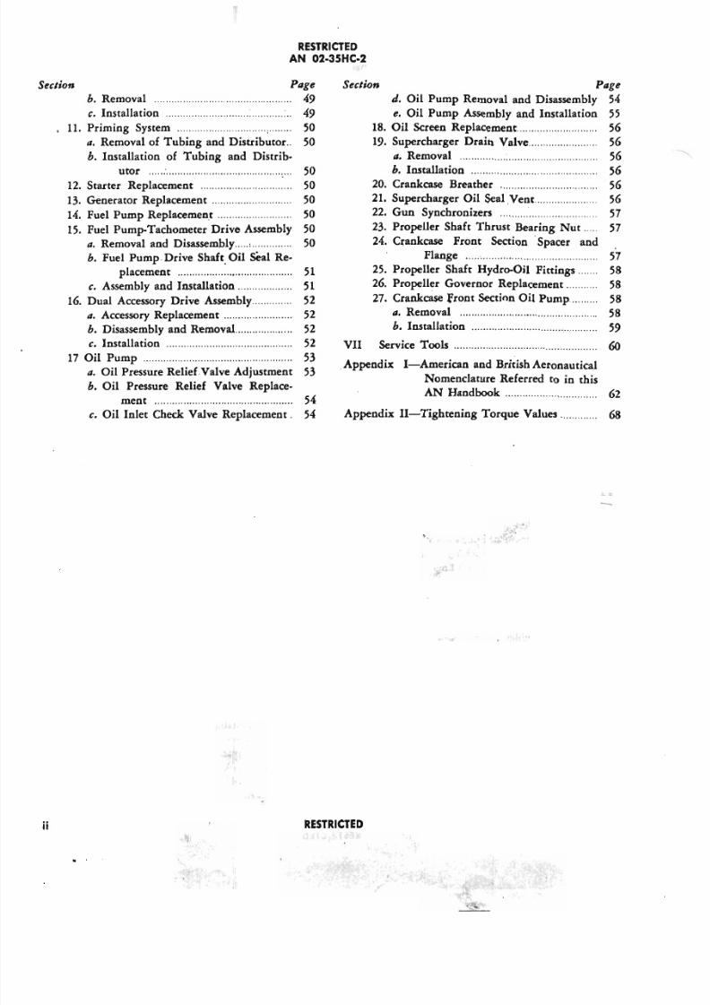
d. Oil Pump Removal and Disassembly 54
e. Oil Pump Assembly and Installation 55
18. Oil Screen Replacement.......................... 56
19. Supercharger Drain Valve........................ 56
a. Removal 56
h. Installation56
20. Crankcase Breather 56
21. Supercharger Oil $eal.Yent...................... 56
22. Gun Synchronizers 57
23. Propeller Shaft Thrust Bearing Nut 57
24. Crankcase Front Section .Spacer and
Flange 57
25. Propeller Shaft Hydro-Oil Fittings....... 58
26. Propeller Governor Replacement........... 58
27. Crankcase Front Section Oil Pump......... 58
II. Removal 58
h. Installation 59
VII Service Tools '" 60.Appendix I-American and British Aeronautical
Nomenclature Referred to in this
AN Handbook 62
Appendix II-Tightening Torque Values 68
RESTRICTED
.'
5/11/2018 Wright 2600 - slidepdf.com
http://slidepdf.com/reader/full/wright-2600 8/77
RESTRICTED
AN 02-35HC-2
: : z : c o : :i a o : a o : C) . . . . :i . . .w w w :J > C)
> ...i > Z . . . . . . . . . ....i cl :
...i
ww
4
Q cl :
. . . . . . . . . . > ~ C)
z z· a o : C)
. . . . . . . . . . . . . z . . . . . w . . .0
~0 0 <II
0 > 0
i= i= a o : i= 0 Z. . . . . . . . :J a o :u
. . . . . u (5. . . . . u
w Z w Z . . . . .Z
Z 0 Z 0; : : :
0 C) zu z u C) <II 0
Z UI U Z
0 w 0 ?: :J ; : : : i=
u . . . . . U <II <II J: :J U
~ :J U . . . . . w
. . . . . co : 0co : . . . . . ; : : : z
z 0 < 0 :J ZJ: . . . . . <II
W c o : u UI 0
> J: 0 a o :w :J U
. . . . . w cl : > co : II>
: : . :. . . . .
VI W cl : w
Z VI a o : C)w
0> ~l: co : a o :co :
. . . . . Q.. : : . : cl : c o : ww0 c o :
~ C) U J:
0 0 c o :w U :JJ: c o : co : VI
u cl : u w W II>
J: Q.. N w
U Q.. :J Z c o :
c o : ~ II>0
Q
wQ..
:J c o ::J a.. J:<II U
z> -I
...i
z·0i=uwZZ0u
. . . . .
zw>c o :w co :J: w. . . . . . . . . . zcl : :5 <c o : co :OIl Z . . . . .
w <II
w W
II> c o : "a..
cl : U ~U
VI :J: : . : w
<II
z·cl :
c o : . . . . .
c o : ~ 0u
RESTRICTED
,;::.'.......
(
5/11/2018 Wright 2600 - slidepdf.com
http://slidepdf.com/reader/full/wright-2600 9/77
RESTRICTED
AN 02-35HC-2
~ 0
IXcta..
ZI-
Z
0 :J
i= 0u ~wZ D..
Z s0 :J
UD..
I-
ZW
>IXwXI-
ctwIXCIl
-l>;::'. .
C > . o
~
-:l
~< u.'": : : . .~"1< u
~. . . .~
C > . o. . . .~~< u
- : - -;;~01~< u
IX . IX;...
~IX- Z I - - <w
I> 00 i= '"u U < u
w . . .0 Z
.~Z zi=
~0 t . . ; . .
:J U
I-
i= IXl-
V!W
CIl
_,
:J ZI- w ~
V! 0Z >
i=:J
IX. . . . IX
w 0 ct.~ u
w w
~ . . . . > I-
IXw w ct
0Z IX ~ Z w
Z w 0 < i:I;
IX 0I-
WU
w X IX w
~ ~ u 0e,
Z I- 0 ct > -
Z. . . . IX I-
0 X wIX
w U . . . .0 Z
I > ct < IX 0
U ~. . . .
~ < i=z z u Z X V!
> - ct ii < U :JV!
l- X IX C OI- W s
Z . . . . .u U a..
:J (5w w :J 0. . . . . s
0 w V! U
iv RESTRICTED
5/11/2018 Wright 2600 - slidepdf.com
http://slidepdf.com/reader/full/wright-2600 10/77
RESTR ICTED
A N 02-3S HC -2
VI C)VI
~ \1'1::) 0. . . . .
o r : : c. . In
Uo r : :
VI Z0
e, 0 ~
~ ~ ~u u uwCC)
e,\1'1 Z
~ Z
:t: ZU w
0« . . . . .
t:0 ~:r : ~~ Z
. . . . .C)
0~
Z ~~
w0 CU ~o r : :w: z : :~~w
~C
. . . . .u
.ZZ
0 0
~ ~uu w . . . . .
w z i5z
zz
0 0 Z
u u 0
w ~w
C)U
C) w
o c t ~ \1'1
C)C) o r : : ~
. . . . . . . . . . ~ zi5 0s « o r : :
: z : :o r : : u..
~~
C) VI w0 VI
. . . . . : z : : c.. ~0
~ u0 ::) ~o r : : o r : : c. . Z·c c . . . . . ~> - > - s o r : :: z : : J: u
RESTR ICTED
5/11/2018 Wright 2600 - slidepdf.com
http://slidepdf.com/reader/full/wright-2600 11/77
RESTR ICTED
A N 02-35H C-2
c o : z . . . co : c o :ILl ct ~ c:E Q
ILl ILl
Z ctZ Q
~-
~Q ~ Q
c o :V ~ 0 . . . .ILl c o :
_. C)
Z ILl W_.
z! : : ! z I- > u.i (5 ~o : ~- 0 C ~
0Z
v v Z C Ill: ~ILl ~ C I-
0. . 0 ~Ll
I- 0 c o : ~ z :EILl c o : 0 Ill: 0Z C)
VI 0 ~ Ill:
C) VI ." V 0
~ 0 ILl ."ILl l-
I- V ILl ~: E . . . v v Z
co :Z ct v Z ILl
C) ~ 0 Z
c t v ILl
:E I-C)
ZILl
>
~ -"w ,
~.._C
<\>. . . .: : : . . ' "
. . .I:l
~, <\>
C(
-..._:: :
" I~<\>;...
:: :~"
1 . 1 . .
::;-~Z0~Q
Q .
c z zz ~ 0 0Q Q ~ ~I-
C)u.. V V
V ILl ILl ILl
ILl Z : : : ; Z ZZ ~ ILl Z ZZ Z
Ill: 0 00 ~ ILl V V
V 0 Ill:
: E~ IU
I-
. . . . VIILl
ILl I- . . . . . .. . . VIILl l- I-
Il': ILl
Z ILl Ill:. . . ~ ~
I- Q Z 0 0. . . eeILl « . . . . . . . . . . . .~ I- (5 (5 (5 0,- VI
vi RESTR ICTED
5/11/2018 Wright 2600 - slidepdf.com
http://slidepdf.com/reader/full/wright-2600 12/77
RESTRICTED
AN 02-35HC-2
Sectio
Par.
SECTION I
INTRODUC710N
1. This publication comprises the Service Instructions
for the Cyclone R-2600-20 and -22 engines manufac-tured by the Wright Aeronautical Corporation, Parer-
son, New Jersey.
2. In this publication the following definitions will
be used:
a. The front of the engine is the propeller end.
b. The rear of the engine is the antipropel1er end.
c. The right and left sides of the engine refer to
the viewpoint of an observer facing the rear of the
engine.
d. The horizontal position refers to the positon of
the engine as in level flight.
e. The rotation of the crankshaft, propeller shaft,
or propeller is clockwise as viewed from the rear of
the engine.
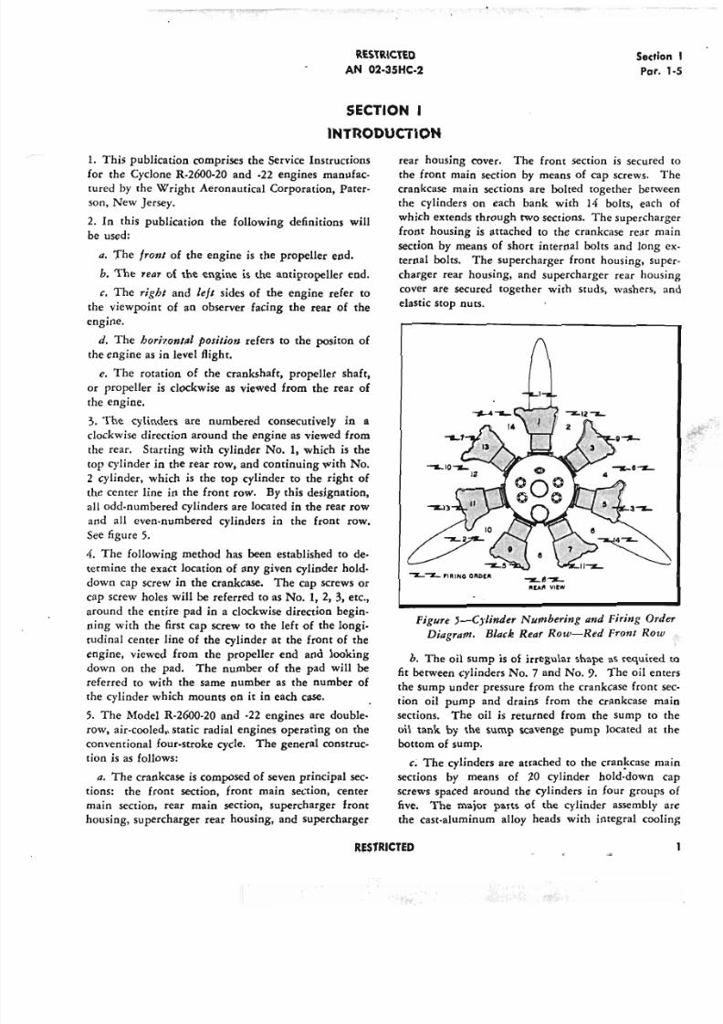
3. The cylinders are numbered consecutively in a
clockwise direction around the engine as viewed from
the rear. Starting with cylinder No.1, which is the
top cylinder in the rear row, and continuing with No.
2 cylinder, which is the top cylinder to the right of
the center line in the front row. By this designation,
all odd-numbered cylinders are located in the rear row
and all even-numbered cylinders in the front row.
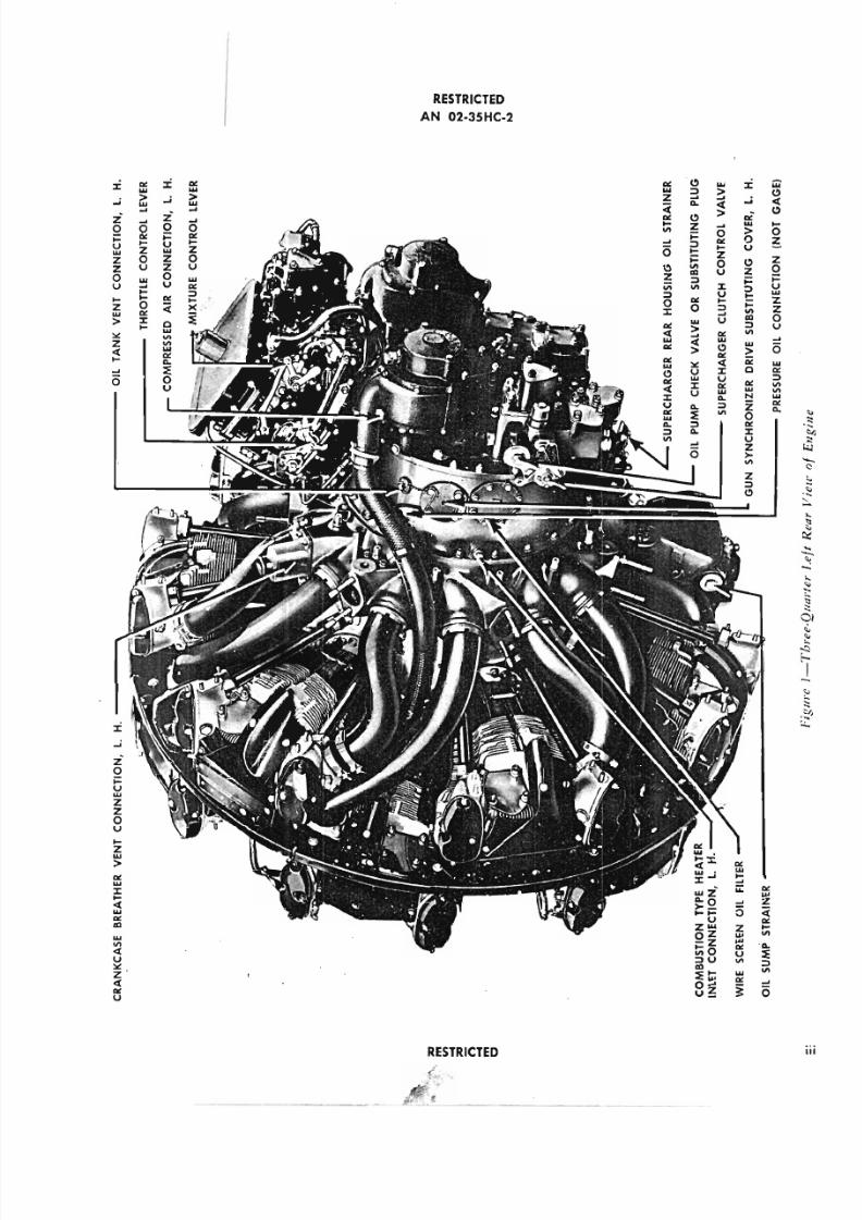
See figure 5.
4. The following method has been established to de-
termine the exact location of any given cylinder hold-
down cap screw in the crankcase. The cap screws or
cap screw holes will be referred to as No.1, 2, 3, etc.,
around the entire pad in a clockwise direction begin-
ning with the first cap screw to the left of the longi-
tudinal center line of the cylinder at the front of the
engine, viewed from the propeller end and looking
down on the pad. The number of the pad will be
referred to with the same number as the number of
the cylinder which mounts on it in each case.
5. The Model R-2600-20 and -22 engines are double-
row, air-cooled, static radial engines operating on the
conventional four-stroke cycle. The general construc-
tion is as follows:
a. The crankcase is composed of seven principal sec-
tions: the front section, front main section, center
main section, rear main section, supercharger front
housing, supercharger rear housing, and supercharger
rear housing cover. The front section is secured
the front main section by means of cap screws.crankcase main sections are bolted together betw
the cylinders on each bank with 14 bolts, each
which extends through two sections. The supercharg
front housing is attached to the crankcase rear m
section by means of short internal bolts and long
ternal bolts. The supercharger front housing, su
charger rear housing, and supercharger rear hous
cover are secured together with studs, washers,
elastic stop nuts.
~e~REAR VI!W
Figure J-C)'linder Numbering and Firing Ord
Diagram. Black Rear Row-Red Front Row
b. The oil sump is of irregular shape as required
fit between cylinders No.7 and No.9. The oil en
the sump under pressure from the crankcase front
tion oil pump and drains from the crankcase m
sections. The oil is returned from the sump to
oil tank by the sump scavenge pump located at
bottom of sump.
c, The cylinders are attached to the crankcase m
sections by means of 20 cylinder hold-down
screws spaced around the cylinders in four groups
five. The major parts of the cylinder assembly
the cast-aluminum alloy heads with integral coo
RESTRICTED
5/11/2018 Wright 2600 - slidepdf.com
http://slidepdf.com/reader/full/wright-2600 13/77
Section I
Par. 5
RESTRICTED
AN 02-35HC-2
fins and rocker boxes which are screwed and shrunk
on steel barrels, the pistons and piston pins with
coiled-spring type retainers, and the piston rings.
The poppet-type valves are located in guides shrunk
in the cylinder head and are operated by a mechan-
ism consisting of rocker arms, push rods, and valvetappets. The tappets are actuated by lobes on a cam
ring driven by a step-down gear train originating at
the crankshaft. Both valves are closed by two high.
frequency valve springs.
d. The crankshaft is ot three-piece construction.
The front and rear secriou., are attached to the center
section by means of clamp je ;nts. The front section
consists of the front crankcheek to which the front
dynamic counterweight is attached and a forward
shaft extension incorporating reduction driving gear
splines. The rear section consists of a crankcheek to
which the rear dynamic damper is attached and a
short hollow shaft extension. Splines and threads are
.cut on the extension to receive the cam drive gear
which is secured by a retaining nut screwed On the
threads. The front and rear dynamic counterweights
are suspended from their crankcheeks on hollow pins
shouldered and tapped on one end to accommodate
the insertion of retaining bolts from the opposite end.
The crankshaft center section consists of two crank-
pins 180 degrees apart, separated by the center main
bearing journal. The three main roller bearings sup- •
porting the crankshaft are constructed with one-piece
roller retainers and are fully demountable for inspec-
tion of all parts.
e. The connecting rod construction consists of two
one-piece type master rods, one assembled on each
crankpin. Six articulated rods are fastened to each mas-
ter rod by knuckle pins, which are held in place by a
steel lock plate. A seal against excessive oil leakage is
provided by a bearing end-seal assembly consisting
of a bearing, the knuckle pin lock plate, and a bronze
spacer. The other end of the master and articulated
rods are connected to the pistons riding in the
cylinders.
[, All accessory drives are effected through spur
gearing in the supercharger rear housing, originating
at the accessory drive gear.
g. The R·2600·20 and -22 engines are equipped with
a two-speed supercharger drive which consists of an
impeller, a diffuser chamber, a distribution chamber,
and an impeller driving mechanism receiving its drive
from the accessory drive gear in the supercharger rear
housing. A drain valve is provided at the lower right
rear portion of the supercharger section to prevent
the accumulation of excess fuel.
h. The lubrication system is of the full-pressure
type, except for the cylinder and piston assemblies
which are lubricated by oil issuing from jets drilled
in each crankpin.
2 RESTRICTED
5/11/2018 Wright 2600 - slidepdf.com
http://slidepdf.com/reader/full/wright-2600 14/77
RESTRICTED
A N 02-3S HC-2
Sectio
Gen
SECTION II
TABLE OF SPECIFICATIONS
GENERAL
Models R·2600·20 and R·2600·22
Type Static Radial, Air-Cooled, Double-Row
Number of Cylinders 14
Bore 6.125 In.
Stroke 6.312 In.
Piston Displacement 2603 Cu In.
Compression Ratio 6.90:1
Impeller Gear Ratio 7.06: 1 and 10.06: 1
Impeller Diameter 11.00 In.
Rotation of Crankshaft (From Antipropeller End)
Clockwise
Rotation of Propeller Shaft (From Antipropeller
End) Clockwise
Propeller Reduction Gear Ratio (Crankshaft to
Propeller)
R-2600-20 16:9
R-2600-22 16:7
AN No. 50, 16 Splines
66.06 In.
Propeller Shaft Spline Size
Overall Length of Engine
Position of Center of Gravity
Distance aft of thrust nut from face 21.71 In.
Distance forward of center line of mounting
bosses 12,43 In.
Distance above center line of crankshaft .31 In.
Number of Mounting Bolts-Plain Mount 7
Diameter of Mounting Bolts-Plain Mouiu .656 In.
Overall Diameter of Engine (Over Front Rocker
Box Cover Studs) 54.08 In.
IGNIT ION
Magneto Type SFI4LU·I0
Rotation of Magneto Drive (From Antipropeller
End) Clockwise
Magneto Drive Shaft Speed Ratio to Crankshaft
.875:1
Spark Timing on Cylinders No. 1 and 12
Left Magneto (Rear Plugs)-Degrees BTC 20°
Right Magneto (Front Plugsr=-Degrees BTC 20°
V A LV ES AN D V A LV E TIM IN G
Intake Opens-Degrees BTC
Intake Closes-Degrees ABC
Exhaust Opens-Degrees BBC
Exhaust Closes-Degrees ATC
Intake Remains Open-Crankangle Degrees
Exhaust Remains Open-Crankangle Degrees
20°
50°
65°
40°
250°
285°
Valve LiftValve Rocker Clearances-Cold
Timing
Running (Hot)
.562
.010
.070
.070
FU EL SY STEM
Carburetor Type
Fuel Required in Flight
Specification
Fuel Inlet Connection Thread
Stromberg PR48
AN-F-28, Grade
AN
Fuel Pressure 13 to 18 Lb per S
Supercharger Drain Valve Connection Thread
.250 In. Std Pipe
LU BR ICA TIO N SY STEM
Oil Required in Flight
Specification AN-VV-O-446, Grade
Oil Pump Drive Shaft Ratio to Crankshaft 1.2
Rotation of Oil Pump Drive Shaft (Facing Drive)
Counterclockw
Flange Attachment to Oil Pump
Inlet and O~tlet
Provision for AN 4037, 4038, 4039, or
Crankcase Vent Connection to Oil Tank
.750 In. Std Pipe
A CCESSORY DRIV E· A N D INSTRU M EN T
CONNECT IONS
Dual Accessory Drive:
Vacuum Pump-Upper (Without AN 4050)
AND 1
Hydraulic Pump-Lower (Without AN 405
and AN 4055) AND 1
Upper and Lower Speed Ratio to Crankshaft
AND 1uel Pump Drive
Fuel Pump Speed Ratio to Crankshaft .8AND 1
3
AND 1
Generator Drive, Type IA
Generator Speed Ratio to Crankshaft
Propeller Governor
Propeller Governor Speed Ratio to Crankshaft
.9
Starter, Type III AND 1
Starter Speed Ratio to Crankshaft
Mechanical Tachometer, Type I AND 1
RESTRICTED
5/11/2018 Wright 2600 - slidepdf.com
http://slidepdf.com/reader/full/wright-2600 15/77
General AN 02-35HC-2
Mechanical Tachometer Speed Ratio to Crank-
shaft .500: 1
Electrical Tachometer, Type II AND 10005 __
Electrical Tachometer Speed Ratio to Crankshaft
.500:1
fuel Pressure Connection Thread
.125 In. Std Pipe Tap
Manifold Pressure Connection, Supercharger
front Housing, L. H. Thread.125 In. Std Pipe Tap
Oil Pressure Connection (Rear Cover Gage)
.125 In. Std Pipe Tap
Combustion- Type Heater, Inlet Connection Thread
.250 In. Srd Pipe Tap
Heater (Exhaust) .500 In. Std Pipe Tap
De-icing Fluid Connection .125 In. Std Pipe Tap
Torquerneter Oil Pressure Connection
.125 In. Std Pipe Tap
Detonation Indicator Connection Thread
.375 In.·24 USF
Static Air Scoop Pressure .125 In. Std Pipe Tap
ACCESSORIES AND WEIGHTS
Basic engine includes integral supercharger, super-
charger drive mechanism, propeller reduction
gears, engine lubrication system, oil pump,
starter connection (including starter dog),
tachometer drives, fuel pump drive, generator
4 RESTRICTED
drive, vacuum pump drive, propeller governor
.drives, all piping and controls between engine
parts, and provision for torquemeter, (If gun
synchronizer impulse generator drives are fur-
nished, it does. not include the impulse gen·
erator.)
Average Weight of Basic Engine including Gun
Synchronizer Drives (R·2600-20) 1877.50 Lb
Average Weight of Basic Engine without GunSynchronizer Drives (R·2600·22) 1873.50 Lb
STANDARD EQUIPMENT
Carburetor Screens and Gaskets
Carburetor and Discharge Assembly
1.50 Lb
50.00 Lb
Magnetos 39.50 Lb
Radio Shielded Ignition Assembly Complete with
Cradle 35.00 Lb
Spark Plugs 7.50 Lb
Priming System Installed on the Engine 2.00 Lb
Cylinder Air Deflectors or Baffles 30.00 Lb
Accessory Drive Covers 2.00 Lb
R·2600·20 TOTAL DRY WEIGHT 2060.00 Lb
TOTAL DRY WEIGHT (WITHOUT
TORQUEMETER) 2045.00 Lb
R·2600·22 TOT AL DRY WEISJHT 2056.00 Lb
TOTAL DRY WEIGHT (WITHOUT
TORQUEMETER) 2041.00 Lb
5/11/2018 Wright 2600 - slidepdf.com
http://slidepdf.com/reader/full/wright-2600 16/77
RESTRICTEDAN 02-35HC-2
SectioPar.
SECTION III
PREPARATION FOR SERVICE OR STORAGE
1. GENERAL.
Q. All engines that are installed in aircraft and that
are to remain idle for a period exceeding 48 hours, and
all engines that are to be stored, will be protected
against corrosion according to the directions given in
this section.
b. The instructions in this section should be fol-
"lowed as closely as possible to guard.against corrosion
and Possible subsequent failure of critical parts.
c. Tbe term "slushing compound" as used in this
section, unless -otherwise specified, denotes a mixture
of 75 percent engine oil Specification No. AN-VV-O-
446, Grade 1120, and 2.5percent corrosion-preventive
compound, Specification No. AN·VV-C-576, blended
in accordance with Specification No. AN·VV-C-576.
d. Ensure that all the material and equipment neces-
sary for the intended operation are available before
starting the operation. The necessary material and
equipment are listed in paragraph 13 of this section.
2. DESCRIPTION OF THE SHIPPING CASE.
Q The engines are shipped in a propeller end up
position i~ a wooden shipping box of the foUowing
dimensions:
Length 65 inches
Width 61-1/4 inches
Height 70-3/8 inches
b. The empty shipping case with fixtures weighs ap-
proximately 840 lb.; with the engine and engine
equipment packed for shipment approximately 2900 lb.
c. The shipping case is divided in two sections. a
lower section or cradle to which the engine is secured,
and an upper section, or cover, in which "the separately
packed carburetor is secured. Each section of the
case is provided with two steel straps secured to the
two
opposite sides of the case , by which the two sec-tions are bolted together. The hooks formed by the
upper ends of-the steel straPs are proyided for lifting
the cover section of the case and must not be used for
lifting the shipping case and engine.
3. REMOVAL FROM THE SHIPPING CASE AND
PREPARATION FOR SERVICE.
II. Break the seals on the shipping case cover attach-
ing bolts and remove the four nuts and bolts.
b. Raise the cover carefully, using a suitable
hoist and sling attached to the hooks formed b
upper ends of the steel straps.
c. Slit the moisture barrier envelope top sea
allow removal of the propeller shaft thread protecto
and'remove the cap. Install the lifting eye (Tool
803485) on the propeller shaft threads and re
the nuts and bolts attaching tbe engine mounting
to the cradle.
d. Attach the chain hoist having a capacity o
tons to the propeller shaft lifting eye and remov
engine and mounting plate from the cradle.
e. Lengthen the slit made in the moisture ba
envelope and roll it down over itse~. Remove th
washers, and bolts and spacen securing the moun
plate to the engine and remove the plate. .Remov
envelope, exercising extreme care to avoid dama
the envelope material.
CAUTION
The moisture barrier envelope should be han
dled only at a temperature of 21°C (70°F) o
above, to reduce the possibility of crackingthe material. Store the envelope for future
use.
I. Remove the heavy creped paper and all deh
tor bags.
g. Install the engine in the aircraft in accord
with the applicable technical order, or mount th
gine on a suitable assembly stand.
h. Remove the dehydrator plugs and the ex
port covers and allow the slushing compound to
from the lower cylinders and intake pipes. Turn
propeller. shaft through five or six revolutions tothe drainage. Reinstall the dehydrator plugs an
haust port coven in all cylinden. Do nor instal
spark plugs until immediately before operating
engine.
i. Remove the sump dehydrator plug and allow
slushing compound (0drain. Remove the keeper
the poles of the magnetic sump plug and instal
magnetic plug and gasket. Tighten and loc
5/11/2018 Wright 2600 - slidepdf.com
http://slidepdf.com/reader/full/wright-2600 17/77
Section III
Par. 3
RESTRICTED
AN 02-3SHC-2
the plug. Remove the oil tank vent sump from the
supercharger rear section cover, and install and lock-
wire the plug.
i - Remove the main oil strainer from the left-hand
side of the supercharger rear housing. Wash thestrainer in clean, unleaded gasoline. Replace the oil
strainer packing ring. gasket and screen. Install it
with washers and elastic lock nuts. and tighten the
nuts to the required torque value.
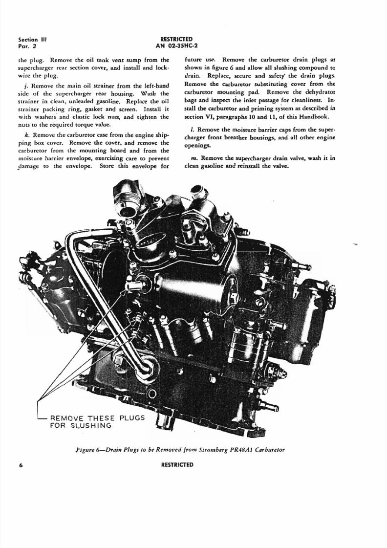
k. Remove the carburetor case from the engine ship-
ping box cover. Remove the cover. and remove the
carburetor from the mounting board and from the
moisture barrier envelope, exercising care to prevent
_Jamage to the envelope. Store this envelope for
future use. Remove the carburetor drain plugs as
shown in figure 6 and allow all slushing compound to
drain. Replace. secure and safety' the drain plugs,
Remove the carburetor substituting" cover from the
carburetor mounting pad. Remove the dehydrator
bags and inspect the inlet passage for cleanliness. In-
stall the carburetor and priming system as described in
section VI, paragraphs 10 and 11, of this Handbook.
I. Remove the moisture barrier caps from the super-
charger front breather housings, and all other engine
openings.
m. Remove the supercharger drain valve, wash it in
clean gasoline and reinstall the valve.
REMOVE TH ES E PLUGS
FOR SLUSH ING
Figure 6-Drain Plugs 10 be Removed from Stromberg PR48AJ Carburetor
6 RESTRICTED
5/11/2018 Wright 2600 - slidepdf.com
http://slidepdf.com/reader/full/wright-2600 18/77
RESTRICTEDAN 02-35HC-2
n. When the engine has been Installed in the air-
craft, remove the exhaust port rovers and gaskets be-
fore installing the collector ring or stacks.
o. Before installing the spark plugs, turn the engine
over five or six revolutions to ensure that all the slush-
ing oil has drained from the lower cylinders and intake
pipes.
p. Install the spark plugs and copper gaskets.
Tighten the spark plugs to the torque value specified
in appendix IIof this Handbook.
q. Remove the terminal protectors from the spark
plug elbows. Install the spark plug elbows, and
tighten the elbow nuts to the required torque value.
Refer to appendix IIof this Handbook.
r. Before starting the engine. pre-oil it according
to the latest technical instructions.
4: S T01lA G E IN FL YA BL EA IR CR A FT .
a. Engines installed in aircraft which are to remain
idle for indefinite periods but which are to be maia-
tained in ayable condition, must be proteeted from
corrosion by either of the following 'methods;
(l)With the aircraft facing into the wind to min-
imize the possibility of excessive cylinder head tem-
peratures, operate the engine at idling speed ODalter-
nate days for a minimum of 15 minutes or Until the
recommended oil-in operating temIJeralUre is reached.
(II) In cold weather, operation may be discon-
tinued after one-half hour. if normal oil-in tempera-
ture cannot be reached by that time. Avoid excessive
ground running, particularly in sandy or dusty areas.
(b) Do Dot exceed 50 percent of rated power
during ground operations.
(c) When these recommendations are carefully
followed the aircraft may be maintained in ayable con-
dition Indefinitely,
(2) ALTERNATE METHOD OF
PROTECI10N:
(II) Change to unleaded fuel, Specification No.
AN-F-22
(b) Drain the engine sumps and oil tank
(c) Refill the oil tank. with slushing compound,
(d) Run the engine for 15 minutes at approxi-
mately 1000 rpm with the propeller in low pitch
(high rpm). Just prior to shutting down, increase the
speed to 1500-1600 rpm, spray hot slushing compound
into the induction system through the carburetor or
SectioPa
any ronvenient connection between the carburetor
the impeller. As soon as smoke becomes appare
the exhaust, set the mixture control in "IDLE
OFF' and continue to spray until the engine stop
(e) Turn off the ign~tion switch.
(/) Care must be exercised that dry air
hydraulic system is employed for spraying.
equipment required for hydraulic spraying is lis
paragraph 13 of this section.
(g). To provide adequate protection from
rosion, this procedure must be repeated each sixth
(h) Operating aircraft lubrication systems
iced with corrosion-preventive compound, wi
drained and refilled with pure engine lubricating
Specification No. AN-VV-0-446, Grade 1120, af
h o u r s of engine operating time.
5. T EM PO R AR Y ST OR AG E.
... Aircraft engines to remain inoperative fo
more than 30 days and taken off FLYABLE statu
be treated for TEMPORARY STORAGE as fo
(1) Run the engine out on slushilig compou
instructed in paragraph 4.a.(2) of this section, an
form the following additional operations:
(II) Remove the magnetic sump plug and
the slushing compound to drain. Wire the plug
its original location for future replacement. The
pound may remain in the oil tank.
(b) Prepare the carburetor as follows:
I.Place the mixture control in "A
RICH" and open the throttle wide.
2. Remove the carburetor drain plu
shown in figure 6, and allow all fuel to drain.
3. Replace the plugs.
(c) Remove the spark plugs and place p
tors over the harness terminal contactors,
(d) Spray hot slushing compound throug
spark plug hole into each cylinder with the pis
the bottom of the cylinder. Do not move theshaft after the.last qlinder has been sprayed. R
each cylinder. to coat the walls which were s
clean while turning the crankshaft. Attach a
the propeller or propeller shaft, warning agains
ther rotation during storage.
(e) Install two cylinder dehydrating plu
each cylinder and attach the harness leads to
See figure 7.
RESTRICTED
5/11/2018 Wright 2600 - slidepdf.com
http://slidepdf.com/reader/full/wright-2600 19/77
Section IIIPar. 5-6
RESTRICTEDAN 02-3SHC-2
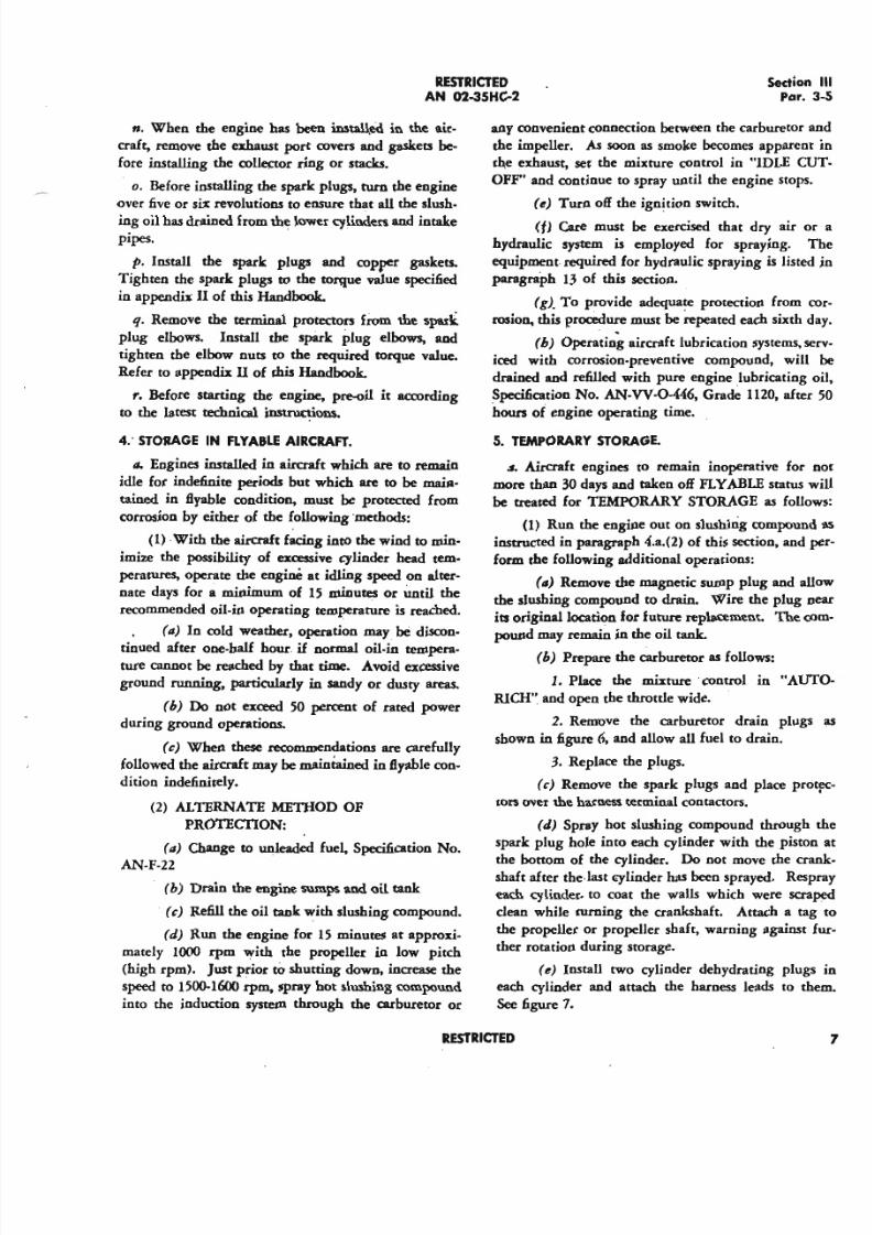
(I) After the compound has thoroughly drained,
install a crankcase dehydrator plug in place of the
magnetic sump plug, as shown in figure 8.
(g) When the propeller is removed, coat the
exposed surface of the propeller shaft inside and outwith preservative compound. Specification No. AN-
C52. Wrap the shaft with a greaseproof acid-free
wrapper, conforming to Specification No. AN-P-12,
Grade A. Type 1. and secure the wrapping. with tape
meeting Specification No. AN-T-l2.
(b) Pack bags of dehydrating agent, Specifica-
tion No, AN-D-6, in the carburetor air scoop and each
cylinder exhaust opening. Cover these openings with
Figure 7-1nsllllling Cylinder Debydrillor Plug
Figure B-lnslalling Crlltlkcase Debydrlllor Plug in
Sump
8
moisture resistant seals and place a dehydrating agent
warning tag at each Iocation,
(i) Cover the crankcase breathers and all other
openings with moisture resistant seals.
(j)Wash the engine thoroughly with a Stod-dard Solvent.
(k) Cover the engine with 'the cover furnished
by the aircraft manufacturer.
b. Engines prepared for storage as directed in JYcl;ra-
graph 5 of this section, will be prepared for operation
in accordance with .the applicable steps in paragraph 3
of this section.
6. EXTENDED STORAGE.
/I. It is preferred that an engine that is to remain
. inoperative for a period exceeding 30 days be removed
from the aircraft. It must then be prepared for stor-
age as directed in paragraph 5 of this section with the
additional precautions Iistedbelow, and packed in ac-
cordance with paragraph 9 of this section.
b. Engines to remain inoperative for more than
thirty days and not removed from the aircraft, will be
prepared for storage as directed under paragraph 5 of
this section. In addition, these extra precautions must
be taken: .
(1) Before spraying the cylinder walls, coat the
exhaust valves and poets with slushing compound.
This may be accomplished by removing the exhaust
stacks, where practical, or spraying through the spark
plug holes. In either case ensure that the exhaust
valve is wide open.
(2) Remove all rocker box covers and thoroughly
spray the rocker boxes and rocker arm assemblies with
slushing compound. Replace the covers and gaskets.
(3) Prepare the carburetor as follows:
(II) Place mixture control in "AUTO-RICH"
and open the throttle wide.
(b) Disconnect the main fuel line; remove the
carburetor drain plugs and elbow, and pour slushing
oil, Specification No. AN-VV-O-446, Grade 1065, into
the fuel-in connection until the, oil draining from the
carburetor appears to have the same consistency as that
being poured in. Allow the oil to drain and replace
.the drain plug elbow and main fuel line.
(c) Where practicable, disconnect the carbure-
tor air scoop and install the cover anddehydrator bag
assembly over the top deck of the carburetor. Cover
this assembly with a moisture resistant seal,
RESTRICTED
5/11/2018 Wright 2600 - slidepdf.com
http://slidepdf.com/reader/full/wright-2600 20/77
RESTR ICTED
A N 02 -35H C·2
(d) Engines prepared for storage according to
the recommendations in this paragraph, will be pre-
pared for operation in accordance with paragraph 3,
of this section.
7. SU B M ER G ED EN G IN ES .
a. Do not raise the engine until preparations for
immediate disassembly and anti-corrosion treatment
are completed. .
b. It is essential that all oil passages and enclosed
areas in the various parts be drained of residual water
after disassembly. When the engine has been sub-
merged in salt .water, all salt encrustations must be
removed by Bushing the parts with fresh water, pre-
ferably warm, until the salt has dissolved; they must
then be thoroughly dried and slushed.
c. Magnesium parts are particularly susceptible tosalt water corrosion. These parts must be carefully
inspected, with particular attention to breaks in the
paint film and unpainted parting surfaces and mount-
ing pads. Wash the parts in unleaded gasoline, Speci-
fication No. AN-F-22, and protect them with a corro-
sion-prevenrive mixture.
8. IN OPE RA BL E E NG ltiES .
a. No preliminary treatment is necessary when the
engine is to be disassembled within 48 hours. When
early disassembly is not practicable, place the engine
on a disassembly stand and perform the followingoperations:
(1) Set the engine in a nose up position.
(2) Remove the propeller governor from its
mounting pad.
(3) Pour or pump a sufficient quantity of sl~hing
compound through the hollow shaft of the governor
drive gear to fill the entire engine.
(4) Replace the governor or a substituting cover.
(5) Remove the thrust bearing nut, pour sufficient
slushing. compound over the exposed thrust bearing
and replace the thrust nut:
(6) Turn the engine to a nose down position to
allow the slushing compound to coat the forward part
of the crankcase front section.
(7) Turn the engine to Bight position.
(8) Remove 'th~ magnetic sump plug and allow
the slushing compound to drain from the engine.
(9) In addition to the above instructions follow
SedionPar.
the recommendations in paragraph 6, EXTEND
STORAGE, as closely as is practicable.
9. PA C KIN G fO R EX TEN DED STO R A G E O R
SH IPMENT .
a. Install the lifting eye (Tool No. 83761) on
propeller shaft threads. Attach a chain hoist of
ton capacity to the engine. Lift the engine, and
stall the shipping box mounting plate attaching
in the bolt holes in the mounting section of the eng
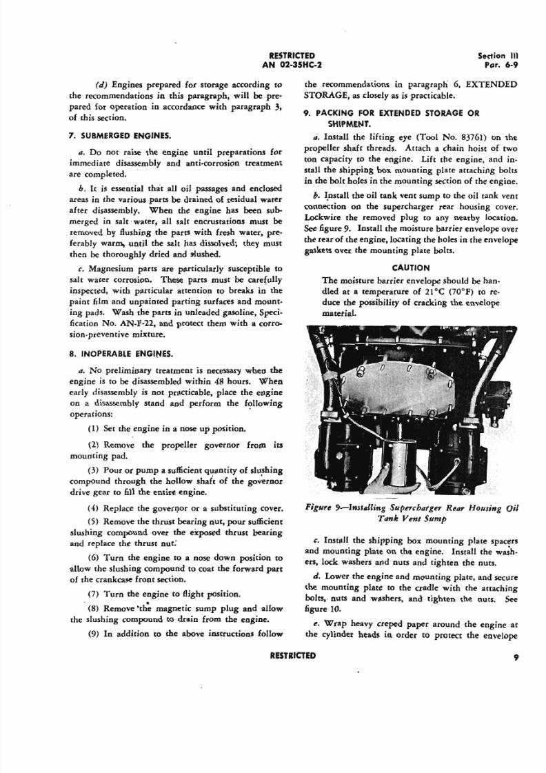
b. I.nstall the oil tank vent sump to the oil tank
connection on the supercharger rear housing c
Lockwire the removed plug to any nearby loca
See figure 9. Install the moisture barrier envelope
the rear of the engine, locating the holes in the enve
gaskets over the mounting plate bolts.
C A U T IO N
The moisture barrier envelope should be han-
dled at a temperature of 21°C (70°F) to reo
duce the possibility of cracking the envelope
matetial.
Figure 9-lnsltJling Supercharger Rear Housing
Tank Yenl Sump
c. Install the shipping box mounting plate sp
and mounting plate on the engine. Install the w
ers, lock washers and nuts and tighten the nuts.
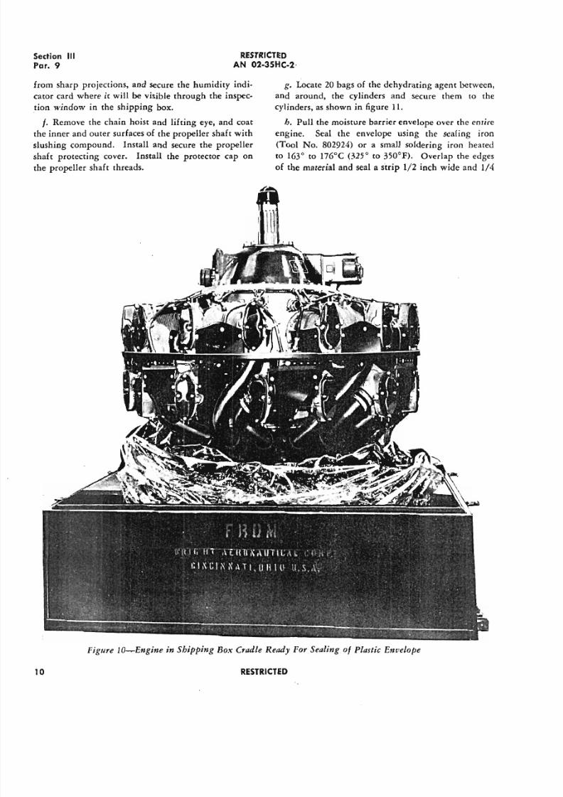
d. Lower the engine and mounting plate, and s
the mounting plate to the cradle with the attac
boles; nuts and washers, and tighten the nuts.
figure 10.
e. Wrap heavy creped paper around the engin
the cylinder heads in order to protect the enve
RESTR ICTED
5/11/2018 Wright 2600 - slidepdf.com
http://slidepdf.com/reader/full/wright-2600 21/77
Section III
Par. 9
RESTR ICTED
A N 02-3S HC -2·
from sharp projections, and secure the humidity indi-
cator card where it will be visible through the inspec-
tion window in the shipping box.
f. Remove the chain hoist and lifting eye, and coat
the inner and outer surfaces of the propeller shaft with
slushing compound. Install and secure the propeller
shaft protecting cover. Install the protector cap on
the propeller shaft threads.
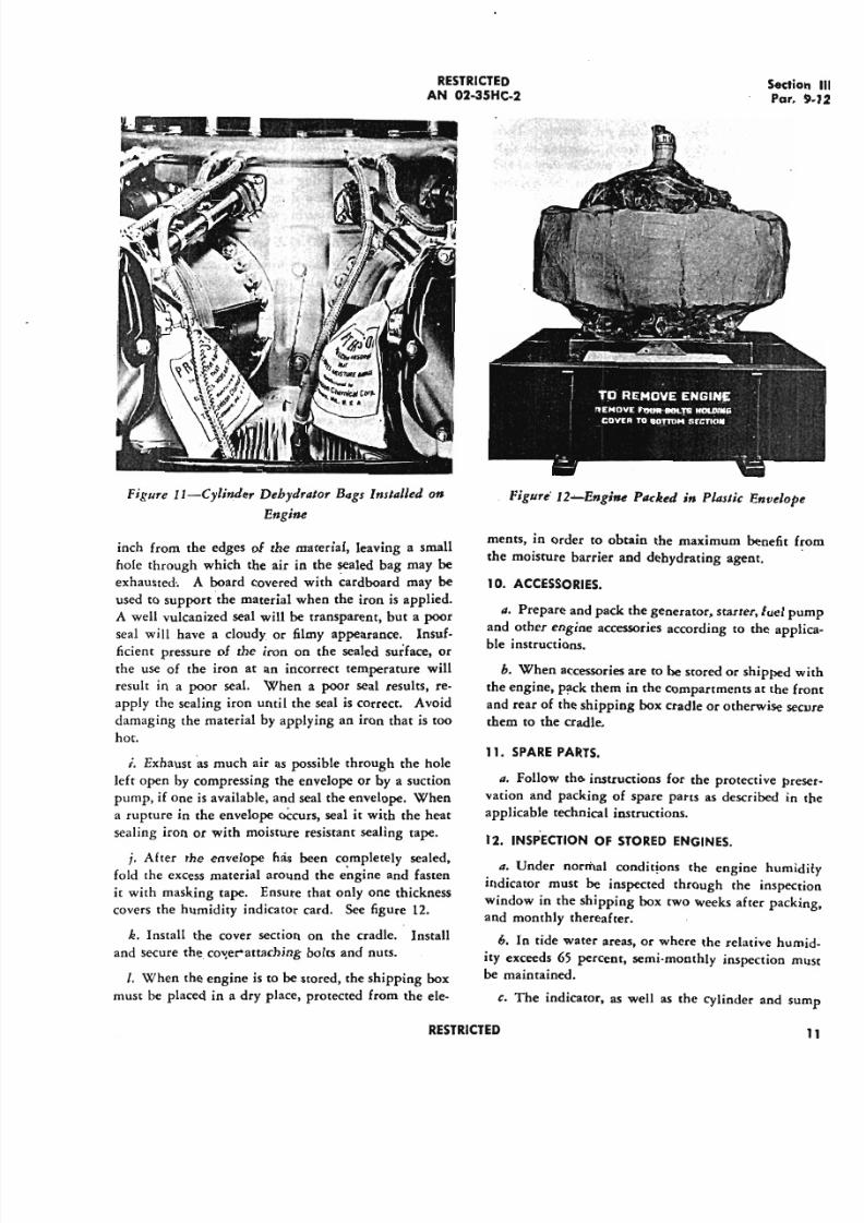
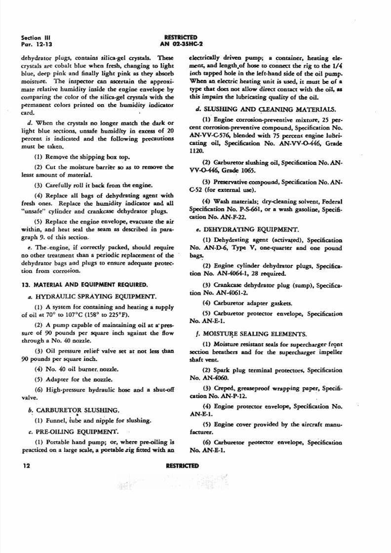
g. Locate 20 bags of the dehydrating agent between,
and around, the cylinders and secure them to the
cylinders, as shown in figure II.
h. Pull the moisture barrier envelope over the entire
engine. Seal the envelope using the sealing iron
(Tool No. 802924) or a small soldering iron heated
to 163° to 176°C (325° to 3500F). Overlap the edges
of the material and seal a strip 1/2 inch wide and 1/4
Figure lO-Engine in Shipping Bo.'I:Cradle Ready For Sealing of Plastic Envelope
10 RESTR ICTED
5/11/2018 Wright 2600 - slidepdf.com
http://slidepdf.com/reader/full/wright-2600 22/77
R E ST R I C T E D
A N 02 -35H C-2
Figure I1-CylinJer Dehydrator Bags Installed on
Engine
inch from the edges of the material, leaving a small
hole through which the air in the sealed bag may be
exhausted·. A board covered with cardboard may be
used to support the material when the iron is applied.
A well vulcanized seal will be transparent, but a poor
seal will have a cloudy or filmy appearance. Insuf-ficient pressure of the iron on the sealed surface, or
the use of the iron at an incorrect temperature will
result in a poor seal. When a poor seal results, re-
apply the sealing iron until the seal is correct. Avoid
damaging the material by applying an iron that is too
hot.
i. Exhaustas much air as possible through the hole
left open by compressing the envelope or by a suction
pump, if one is available, and seal the envelope. When
a rupture in the envelope O C c u r s , seal it with the heat
sealing iron or with moisture resistant sealing tape.
j. After the envelope has been completely sealed,
fold the excess material around the engine and fasten
Ir with masking tape. Ensure that only one thickness
covers the humidity indicator card. See figure 12.
k. Install the cover section on the cradle. Install
and secure the. cover-attaching bolts and nuts.
I. When the engine is to be stored, the shipping box
must be placed in a dry place, protected from the ele-
R E ST R I C T E D
SectPar
Figur« 12~Engine Packed in Plastic Envelo
ments, in order to obtain the maximum benefit
the moisture barrier and dehydrating agent.
10. A C CE SS O RIE S.
II. Prepare and pack the generator, starter, fuel
and other engine accessories according to the ap
ble instructions.
h. When accessories are to be stored or shipped
the engine, pack them in the compartments at the
and rear of the shipping box cradle or otherwise s
them to the cradle.
11. S PA RE PA RT S .
II. Follow the instructions for the protective p
vation and packing of spare parts as described i
applicable technical instructions.
12 . IN SPE C T IO N O F ST O R E D E N G IN E S .
a. Under normal conditions the engine hum
indicator must be inspected through the inspec
window in the shipping box two weeks after pack
and monthly thereafter.
h. In tide water areas, or where the relative hu
ity exceeds 65 percent, semi-monthly inspection
be maintained.
c. The indicator, as well as the cylinder and
5/11/2018 Wright 2600 - slidepdf.com
http://slidepdf.com/reader/full/wright-2600 23/77
Sedion III
Par. 12-13RESTRICTEDAN 02-35HC-2
dehydrator plugs. contains silica-gel crystals. These
crystals are cobalt blue when fresh, changing to light
blue, deep pink and finally light pink as they absorb
moisture. The inspector can ascertain the approxi-
mate relative humidity inside the engine envelope by
comparing the color of the silica-gel crystals with the
permanent colors printed on the humidity indicator
card.
d. When the crystals no longer match the dark or
light blue sections, unsafe humidity in excess of 20
percent is indicated and the following precautions
must be taken.
(1) Remove the shipping box top.
(2) Cut the moisture barritr so as to remove the
least amount of material.
(3) Carefully roll it back from the engine.
(4) Replace all bags of dehydrating agent with
fresh ones. Replace the humidity indicator and all
"unsafe" cylinder and crankcase dehydrator plugs.
(5) Replace the engine envelope, evacuate the air
within, and heat seal the seam as described in para-
graph 9. of this section,
e. The-engine, if correctly packed, should require
no other treatment than a periodic replacement of the
dehydrator bags and plugs to ensure adequate protec-
tion from corrosion.
13. MATERIAL AND EQUIPMENT REQUIRED.
II. HYDRAULIC SPRAYING EQUIPMENT.
(1) A system for containing and heating a supply
of oil at 70° to 107°C (1580
to 225°F).
(2) A pump capable of maintaining oil at a' pres-
sure of 90 pounds per square inch against the flow
through a No. 40 nozzle.
(3) Oil pressure relief valve set at not less than
90 pounds per square inch.
(4) No. 40 oil burner. nozzle.
(5) Adapter for the nozzle.
(6) High-pressure hydraulic hose and a shut-off
valve.
b. CARBURETOR SLUSHING.. .(1) Funnel, rube and nipple for slushing.
c. PRE-OILING EQUIPMENT.
(1) Portable hand pump; or, where pre-oiliog is
practiced on a large scale, a portable .rig fitted with an
electrically driven pump; a container. heating ele-
ment, and Iength.of hose to coaaect the rig to the II"inch tapped hole in the left-hand side of the oil pump.
When an electric heating unit is used, it must be of a
type that does not allow direct contaCt with the oil, as
this impairs the lubricating quality of the oil.
J. SLUSHING AND a.EANING MATERIALS.
(1) Engine corrosion-preventive mixture, 25 per-
cent corrosion-preventive compound, Specification No.
AN-VV-C576, blended with 75 percent engine lubri-
cating oil, Specification No. AN- VV-O-M6, Grade
1120.
(2) Carburetor slushing oil, Specification No. AN-
VV -0-«6, Grade 1065.
(3) Preservative compound, Specification No. AN-
C52 (for externaluse).
(") Wash materials; dry-cleaning solvent. Federal
Specification No. P-S-661, or a wash gasoline, Specifi-
cation No. AN-F-22.
e. DEHYDRATING EQUIPMENT.
(1) Dehydrating agent (activated), Specification
No. AN-D-6, Type V, one-quarter and one pound
bags,
(2) Engine cylinder dehydrator plugs, Specifica-
tion No. AN-4064-1, 28 required.
(3) Crankcase dehydrator plug (sump), Specifica-
tion No. AN4061-2.
(") Carburetor adapter gaskets,
(5) Carburetor protector envelope, Specification
No. AN-E-l.
t- MOISTIJl!E SEAUNG ELEMENTS.
(1) Moisture resistant seals for supercharger fC<}nt
section breathers and for the supercharger impeller
shaft vent.
(2) Spark plug terminal protectors, Specification
No. AN4060.
(3) Cteped, greaseproof wrapping paper, Specifi-
cation No. AN-P-l2. .
(4) Engine protector envelope, Specification No.
AN-E-l.
(5) Engine cover provided by the aircraft manu-
facturer.
(6) Carburetor protector envelope, Specification
No. AN-E-l.
12 R E S T R I C T E D
5/11/2018 Wright 2600 - slidepdf.com
http://slidepdf.com/reader/full/wright-2600 24/77
RESTRlcrm·
AN 02-35HC-2Sectio
Par
\ I) Adhesive moisture proof tape, Specffication
No. AN-T-l2.
g. HEATING IRON SEAIJNG TOOL
(1) For heat' sealing the engine and carburetor
moisture barrier envelopes (Tool No. 8om4).
b. WARNING CARDS.
(1) Humidity indicator card (large).
(2) Warning ca rds to direct the removal of m
ture seals and dehydrating agents from tag locati
-P"ges 14, 15, tmJ 16 Deleled
. R ESTR lC IED

5/11/2018 Wright 2600 - slidepdf.com
http://slidepdf.com/reader/full/wright-2600 25/77
5/11/2018 Wright 2600 - slidepdf.com
http://slidepdf.com/reader/full/wright-2600 26/77
RESTR ICTED
AN 02-35HC-2
S e ction
Pa
SECTION IV
ENGINE TROUBLES AND SERVICE REPAIRS
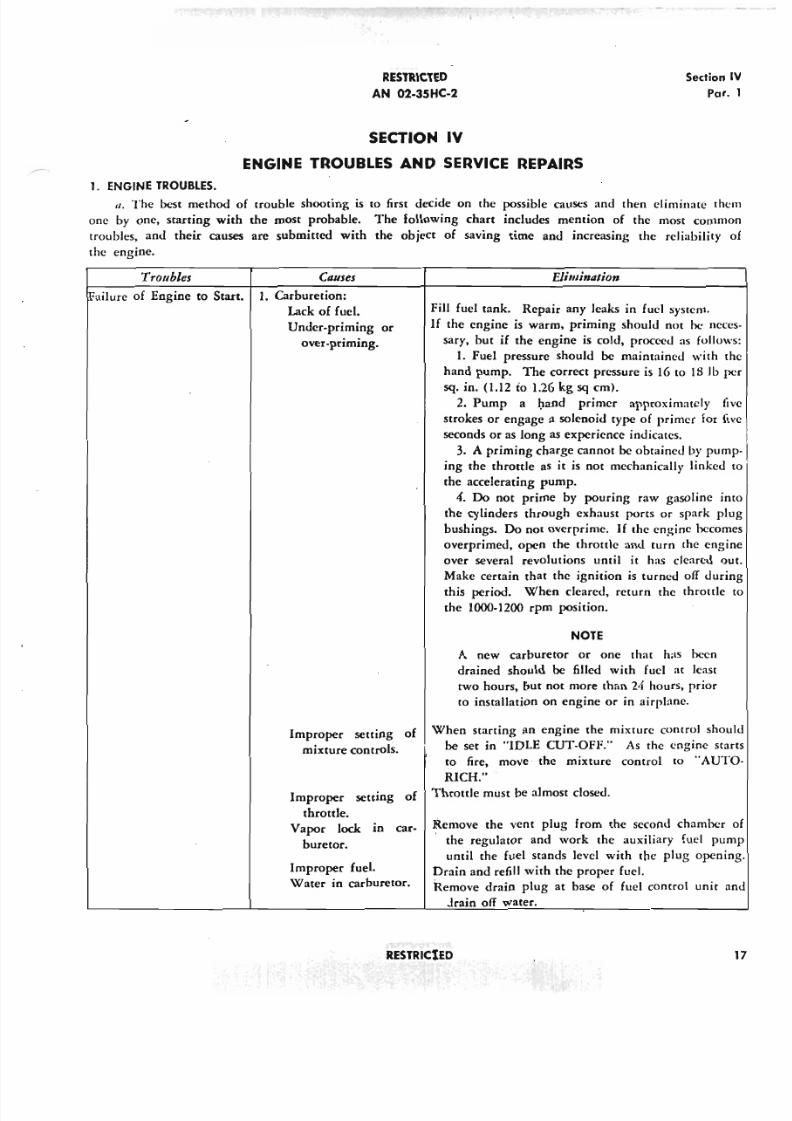
1. E NG IN E T RO UB LE S.
a, The best method of trouble shooting is to first decide on the possible causes and then eliminate th
one by one, starting with the most probable. The following chart includes mention of the most comm
troubles, and their causes are submitted with the object of saving time and increasing the reliability
the engine.
Troubles Causes
!Failure of Engine to Start. 1. Carburetion:
Lack of fuel.
Under-priming or
over-priming.
Improper setting of
mixture controls.
Improper setting of
throttle.
Vapor lock 10 car-
buretor.
Improper fuel.
Water in carburetor.
Eli mineslo»
Fill fuel tank. Repair any leaks in fuel system.
If the engine is warm, priming should not he nec
sary, but if the engine is cold, proceed as follow
I.Fuel pressure should be maintained with
hand pump. The correct pressure is 16 to 18 lb
sq. in. (1.12 to 1.26 kg sq em).2. Pump a hand primer approximately
strokes or engage a solenoid type of primer for
seconds or as long as experience indicates.
3. A priming charge cannot be obtained by pum
ing the throttle as it is not mechanically linked
the accelerating pump.
4. Do not prime by pouring raw gasoline i
the cylinders through exhaust ports or spark p
bushings. Do not overprime. If the engine becom
overprimed, open the throttle and turn the eng
over several revolutions until it has cleared o
Make certain that the ignition is turned off duri
this period. When cleared, return the throttle
the 1000-1200 rpm position.
N O TE
A new carburetor or one that has heen
drained should be filled with fuel at least
two hours, bur not more than 24 hours, prior
to installation on engine or in airplane.
When starting an engine the mixture control sho
be set in "IDLE CUT-OFF." As the cngine st
to fire, move the mixture control to "AUT
RICH."Throttle must be almost closed.
Remove the vent plug from the second chamber
the regulator and work the auxiliary fuel pu
until the fuel stands level with the plug openi
Drain and refill with the proper fuel.
Remove drain plug at base of fuel control unit
Jrain off water.
RESTR iC tED
5/11/2018 Wright 2600 - slidepdf.com
http://slidepdf.com/reader/full/wright-2600 27/77
Section IV
Par. 1
RESTRICTED
AN 02-35HC-2
Ceuses
ENGINE TROUBLES--{Co"ti"ueJ)
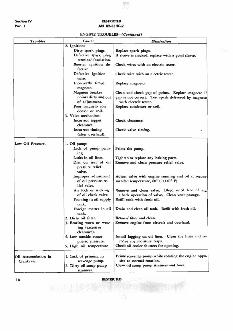
Elimi1llllionroubles
2. Jgnition:
Dirty spark plugs.
Defective spark plug
terminal insulation.
Booster ignition de-
fective.
Defective ignition
wire.
Incorrectly timed
magneto.
Magneto breaker
points dirty and out
of adjustment.
Poor magneto con-
denser or coil.
3. Valve mechanism:
Incorrect tappet
clearance.
Incorrect timing
(after overhaul).
Replace spark plugs.
If sleeve is cracked, replace with a good sleeve.
Check wires with an electric tester.
Check wire with an electric tester.
Replace magneto.
Clean and check gap of points. Replace magneto if
gap is not correct. Test spark delivered by magneto
with electric tester.
Replace condenser or coil.
Check clearance.
Low Oil Pressure.
Check valve timing.
Oil Accumulation IQ
Crankcase.
1. Oil pump:
Lack of pump prim- Prime the pump.
ing.
Leaks in oil lines.
Dirt on seat of oil
pressure relief
valve.Improper adjustment
of oil pressure re-
lief valve.
Air lock or sticking
of oil check valve.
Foaming in oil supply
tank.
Foreign matter in oil
tank.
2. Dirty oil filter.
3. Bearing worn or wear-
ing (excessive
clearance).
4. Low outside atmos-
pheric pressure.
5. High oil temperature
1. Lack of priming in
scavenge pump.
2. Dirty oil sump pump
strainers.
Tighten or replace any leaking parts.
Remove and clean pressure relief valve.
Adjust valve with engine running and oil at recom-
mended temperature, 600 C (1400 F).
Remove and clean valve. Bleed until free of air.
Check operation of valve. Dean vent passage.
Refill tank with fresh oil
Drain and clean oil tank. Refill with fresh oil.
Remove filter and clean.
Remove engine from aircraft and overhaul.
Install lagging on oil lines. Clean the lines and re-
move any moisture traps.
Check oil cooler shutters for opening.
Prime scavenge pump while rotating the engine oppo-
site to normal rotation.
Clean oil sump pump strainers and lines.
18 RESTRICTED
5/11/2018 Wright 2600 - slidepdf.com
http://slidepdf.com/reader/full/wright-2600 28/77
RESTRICTED
AN 02-35HC-2
Sedio
P
Causes
ENGINE TROUBLES-(Conlinuea)
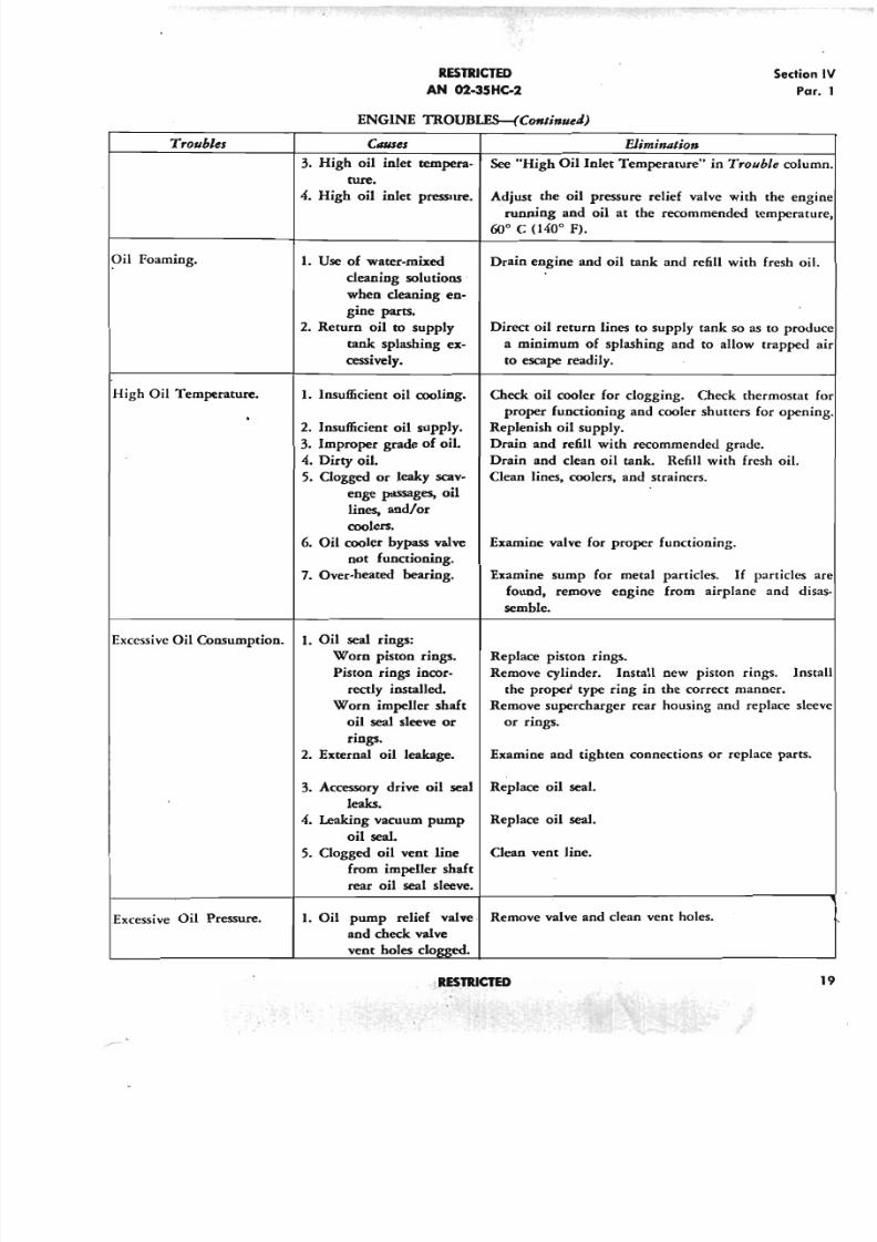
Eliminationroubles
3. High oil inlet tempera-
ture.
4. High oil inlet pressure. Adjust the oil pressure relief valve with the en
running and oil at the recommended tempera
60° C (l,mo F).
See "High Oil Inlet Temperature" in Trouble col
Oil Foaming. Drain engine and oil tank and refill with fresh o
High Oil Temperature. 1. Insufficient oil cooling.
Excessive Oil Consumption. 1. Oil seal rings:
Worn piston rings.
Piston rings incor-
rectly installed.
Worn impeller shaft
oil seal sleeve or
rings.
2. External oil leakage. Examine and tighten connections or replace part
3. Accessory drive oil seal Replace oil seal.
leaks.
4. Leaking vacuum pump Replace oil seal.
oil seal .
5. Clogged oil vent line Clean vent line.
from impeller shaft
rear oil seal sleeve.
1. Use of water-mixed
cleaning solutions
when cleaning en-
gine pacts.
2. Return oil to supply
tank splashing ex-
cessively.
2. Insufficient oil supply.
3. Improper grade of oil.
4. Dirty oil.
5. Clogged or leaky scav-
enge passages, oil
lines, and/or
coolers.
6. Oil cooler bypass valve
not functioning.
7. Over-heated bearing.
Direct oil return lines to supply tank so as to pro
a minimum of splashing and to allow trapped
to escape readily.
Check oil cooler for clogging. Check thermostat
proper functioning and cooler shutters for ope
Replenish oil supply.
Drain and refill with recommended grade.
Drain and clean oil tank. Refill with fresh oil.
Clean lines. coolers. and strainers.
Examine valve for proper functioning.
Examine sump for metal particles. If particles
found. remove engine from airplane and d
semble.
Replace piston rings.
Remove cylinder. Install new piston rings. In
the proper type ring in the correct manner.
Remove supercharger rear housing and replace s
or rings.
Excessive Oil Pressure. 1. Oil pump relief valve· Remove valve and clean vent holes.
and check valve
vent holes clogged.
RESTRICTED
5/11/2018 Wright 2600 - slidepdf.com
http://slidepdf.com/reader/full/wright-2600 29/77
- - - - - - - - - . ~ - - - - ~ - - - - ~ - - - - ~ - - - - - - - - - - - - - - ~ ~ ~ - - - - - -
Section IV
Par. 1
RESTRICTED
AN 02-35HC-2
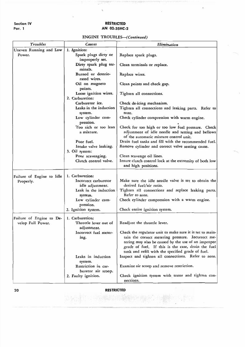
ENGINE TROUBLES-(Conlinued)
Troubles
Uneven Running and Low
Power.
Failure of Engine to Idle
Properly.
Causes Eliminalion
1. Ignition:
Spark plugs dirty or Replace spark plugs.
improperly set.
Dirty spark plug ter- Clean terminals or replace.
minals.
Burned or deterio- Replace wires.
rated wires.
Oil on magneto
points.
Loose ignition wires.
2. Cnrburetion:
Carburetor icc.
Leaks in the induction
system.
Low cylinder com-
pression.
Too dch or too lean
a mixture.
Poor fuel.
Intake valve leaking.
3. Oil system:
Poor scavenging.
Clutch control valve.
1. Carburetion:
Incorrect carburetor
idle adjustment.
Leak in the induction
system.
Low cylinder com-
pression.
2. Ignition system.
Clean points and check gap.
Tighten all connections.
Check de-icing mechanism.
Tighten all connections and leaking parts. Refer to
note.
Check cylinder compression with warm engine.
Check for too high or too low fuel pressure. Check
adjustment of idle needle and setting and bellows
ofthe automatic mixture control unit.
Drain fuel tanks and fill with the recommended fuel.
Remove cylinder and correct valve seating cause.
Clean scavenge oil lines.
Insure clutch control lock at the extremity of both low
and high positions.
Make sure the idle needle valve is set to obtain the
desired fuel/air ratio.
Tighten all connections and replace leaking parts.
Refer to note.
Check cylinder compression with a warm engine.
Check entire ignition system.
Failure of Engine to De-
velop Full Power.
1. Carburetion:
Throttle lever out of
adjustment.
Incorrect fuel meter-
ing.
Leaks in induction
system.
Restriction in car-
buretor air scoop.
2. Faulty ignition.
Readjust the throttle lever.
Check the regulator unit to make sure it is set to main-
tain the correct metering pressure. Incorrect me-
tering may also be caused by the use of an improper
grade of fuel. If this is the case, drain the fuel
tank and refill with the specified grade of fuel.
Inspect and tighten all connections. Refer to note.
Examine air scoop and remove restriction.
Check ignition system with tester and tighten con-
nections.
20 RESTRICTED
5/11/2018 Wright 2600 - slidepdf.com
http://slidepdf.com/reader/full/wright-2600 30/77
RESTRICTED
A N 02-35H C-2
Sedi
Pa
ENGINE TROUBLES-(Conlinued)
Troubles Causes Elimination
Rough Engine. 1. Engine mount:
Cracked mount. Replace or repair mount.
Defective bushings. Replace with new bushings.
2 . Governor control. Refer to the applicable technical order.
3. Propeller blade settings. Check that all blades are set equally.
4. Malfunctioning engine. Check all previously listed engine troubles.
Do not tighten intake pipe packing nuts after "A" period of operation. Tightening of the
intake pipe packing nuts within "A" period of operation after installing new rubber packing
is permissible, because at this time the rubber packing is still soft and has not adhered tightly
to the nut and pipe. Leaking intake pipe packing is a fire hazard and a possible cause of
improper mixture strength. Caution must be observed in following these recommendations.
2 . COLD W EATHER PRECAUTIO NS.
a. In cold weather it is advisable to have some sort
of lagging on the external oil lines on the engine and
to and from the oil tank. This will decrease the danger
of stoppage due to local congealed oil. A layer of
asbestos cord coated with shellac or water glass and
then wrapped in friction tape provides very good
insulation. Lacking asbestos, several layers of ordi-
nary packing cord can be used.
b. Unless the Auto-Syn system of transmitting the
engine oil pressures to the cockpit gages is utilized, it
is recommended that all pressure gage lines be filled
with oil, Specification AN- 0·6, for cold weather opera-
tion. After the lines are filled with this oil, all con-
nections should be kept tight to prevent leakage.
c. Make sure the crankcase front section cold
weather cowl is installed on the engine.
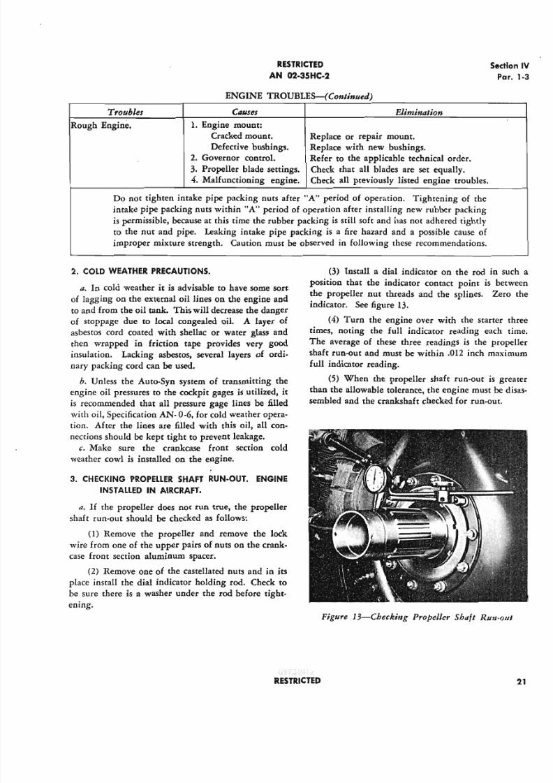
3. CHECKING PROPELLER SHAFT RU N -OUT . ENG INE
INSTALLED IN A IRCRAFT .
a. If the propeller does not run true, the propeller
shaft run-out should be checked as follows:
(1) Remove the propeller and remove the lock
wire from one of the upper pairs of nuts on the crank-case front section aluminum spacer.
(2) Remove one of the castellated nuts and in its
place install the dial indicator holding rod. Check to
be sure there is a washer under the rod before tight-
ening.
(3) Install a dial indicator on the rod in sposition that the indicator contact point is be
the propeller nut threads and the splines. Zer
indicator. See figure 13.
(4) Turn the engine over with the starter
times, noting the full indicator reading each
The average of these three readings is the prop
shaft run-out and must be within .012 inch maxi
full indicator reading.
(5) When the propeller shaft run-out is g
than the allowable tolerance, the engine must be
sembled and the crankshaft checked for run-out.
Figure 13-Checking Propeller Shaft Run-ou
RESTR ICTED
5/11/2018 Wright 2600 - slidepdf.com
http://slidepdf.com/reader/full/wright-2600 31/77
Section IV
Par. 4
RESTRICTED
AN 02-35HC-2
4. DRAIN VALVE LEAKAGE. c. If leakage is evidenced with the disk-type super-
charger drain valve at full throttle and high altitude
only, throttle back slightly and reduce altitude a suffi-
cient amount to increase the pressure differential, and
when flight is completed, correction should he made.
As this is an installation problem, the correction is to
install a new drain that will extend into the area of
positive pressure and face forward into the slip
stream.
II. Leakage of the supercharger drain valve during
engine operation is often caused by dirt or foreign
matter which hinders the sliding action of the piston
or which prevents proper seating of the disk.
b. In some instances, valve faces may require lap-
ping co cffcct the proper seal. Improper fit of the
piston in the valve body is another cause of leakage.
22 RESTRICTED
5/11/2018 Wright 2600 - slidepdf.com
http://slidepdf.com/reader/full/wright-2600 32/77
RESTRJCTED
AN 02-3SHC-2
Sectio
Gen
SECTION V
SERVICE INSPECTION AND ASSOCIATED MAINTENANCE
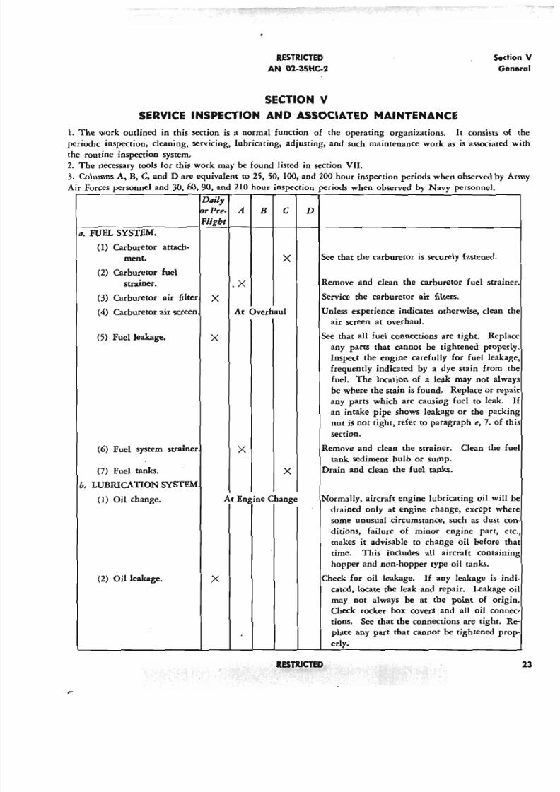
1. The work outlined in this section is a normal function of the operating organizations. It consists ofperiodic inspection, cleaning, servicing, lubricating, adjusting, and such maintenance work as is associated
the routine inspection system.
2. The necessary tools for this work may be found listed in section VII.
3. Columns A, B, C . and D are equivalent to 25, 50, 100, and 200 hour inspection periods when observed by A
Air Forces personnel and 30,60,90, and 210 hour inspection periods when observed by Navy personnel.
Dail,
Dr Pre- A B C D
Flight
a. FUEL SYSTEM.
(1) Carburetor attach-
ment. X
(2) Carburetor fuel
strainer. .X
(3) Carburetor air filter X
(4) Carburetor air screen At Overhaul
(5) Fuel leakage. X
At Engine Change
X6) Fuel system strainer
(7) Fuel tanks.
h. LUBRICATION SYSTEM
(1) Oil change.
(2) Oil leakage. X
See that the carburetor is securely fastened.
X
Remove and clean the carburetor fuel strainer
Service the carburetor air filters.
Unless experience indicates otherwise, clean th
air screen at overhaul.
See that all fuel connections are tight. Replac
any parts that cannot be tightened properly
Inspect the engine carefully for fuel leakage
frequently indicated by a dye stain from th
fuel. The location of a leak may not alway
be where the stain is found. Replace or repa
any parts which are causing fuel to leak.an intake pipe shows leakage or the packing
nut is not tight, refer to paragraph e, 7. of th
section.
Remove and clean the strainer. Clean the fu
tank sediment bulb or sump.
Drain and clean the fuel tanks.
Normally, aircraft engine lubricating oil will
drained only at engine change, except wher
some unusual circumstance, such as dust co
ditions, failure of minor engine part, er
makes it advisable to change oil before th
time. This includes all aircraft containing
hopper and non-hopper type oil tanks.
Check for oil leakage. If any leakage is ind
cated, locate the leak and repair. Leakage o
may not always be at the point of origin
Check rocker box covers and all oil connec
tions. Se e that the connections are tight. R
place any part that cannot be tightened prop
erly.
RESTRICTED
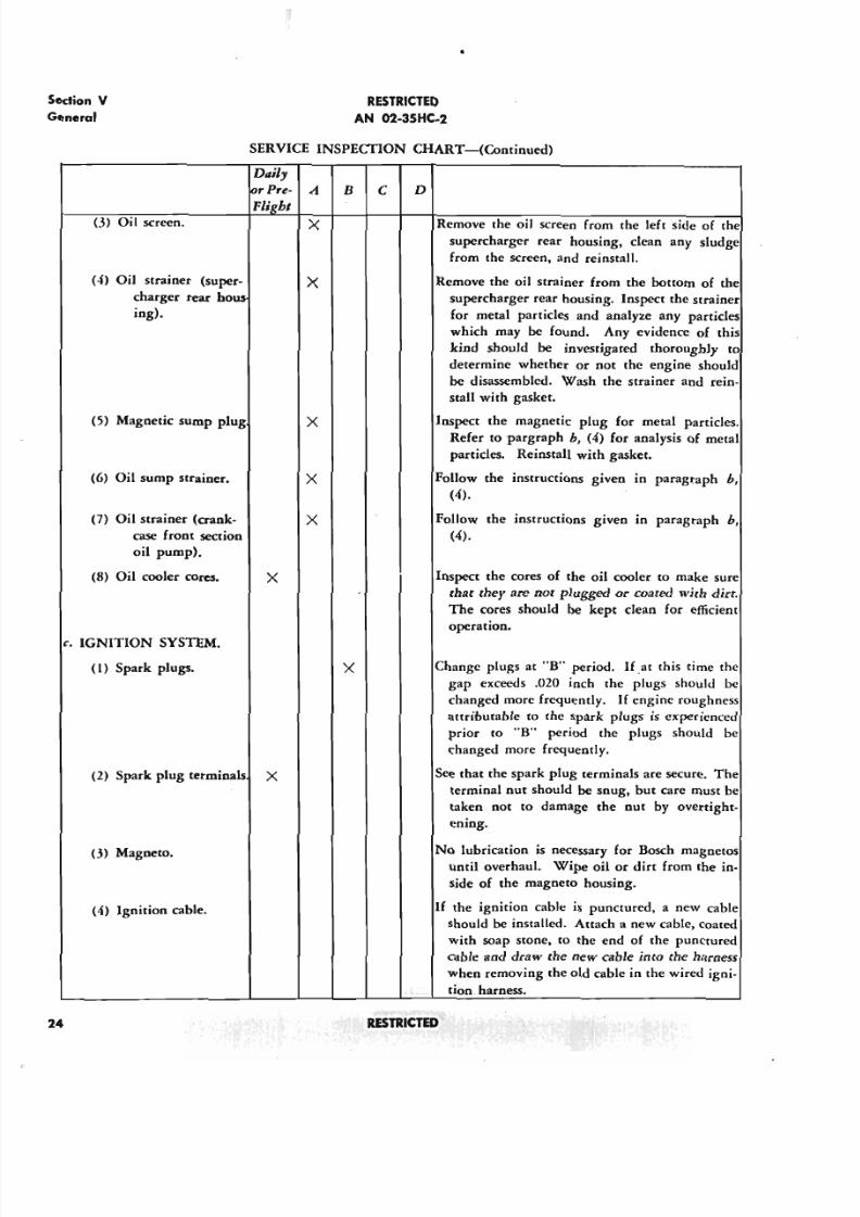
5/11/2018 Wright 2600 - slidepdf.com
http://slidepdf.com/reader/full/wright-2600 33/77
Section V
General
T
R E S T R I C T E D
AN 02-35HC-2
•
SERVICE INSPECfION CHART-(Continued)
(6) Oil sump strainer. X
(7) Oil strainer (crank- Xcase front section
oil pump).
(8)Oil cooler cores. X
(3) Oil screen.
(4) Oil strainer (super-
charger rear hous-
ing).
(5) Magnetic sump plug
Daily
lor Pre- A
FlighJ
X
x
X
B
c. IGNITION SYSTEM.
( I) Spark plugs. X
(2) Spark plug terminals X
(j)Magneto.
(4) Ignition cable.
24
c
R E S T R . ' C l E D
D
Remove the oil screen from the left side of the
supercharger rear housing, clean any sludge
from the screen, and reinstall.
Remove the oil strainer from the bottom of the
supercharger rear housing. Inspect the strainer
for metal particles and analyze any particles
which may be found. Any evidence of this
kind should be investigated thoroughly to
determine whether or not the engine should
be disassembled. Wash the strainer and rein-
stall with gasket.
Inspect the magnetic plug for metal particles.
Refer topargraph b, (4) for analysis of metal
particles. Reinstall with gasket.
Follow the instructions given in paragraph b,
(4).
Follow the instructions given in paragraph b,
(4).
Inspect the cores of the oil cooler to make sure
that they ace not plugged or coated with dirt.
The cores should be kept clean for efficient
operation.
Change plugs at "B" period. If at this time the
gap exceeds .020 inch the plugs should be
changed more frequently. If engine roughness
attributable to the spark plugs is experienced
prior to "B" period the plugs should be
changed more frequently.
See that the spark plug terminals are secure. The
terminal nut should be snug, but care must be
taken not to damage the nut by overtight-
ening.
No lubrication is necessary for Bosch magnetos
until overhaul. Wipe oil or dirt from the in-
side of the magneto housing.
If the ignition cable is punctured, a new cable
should be installed. Attach a new cable, coated
with soap stone, to the end of the punctured
cable and draw the new cable into the harness
when removing the old cable in the wired igni-
tion. harness.
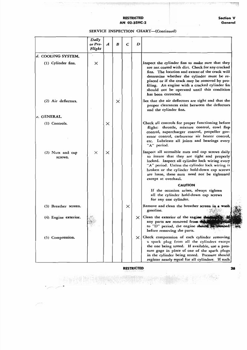
5/11/2018 Wright 2600 - slidepdf.com
http://slidepdf.com/reader/full/wright-2600 34/77
RESTRICTED
AN 02-35HC-2
Secti
Ge
SERVICE INSPECI10N CHAR1'-(Continued)
Dttily
or Pre- A
Fligbl
d. COOLING SYSTEM.
(1) Cylinder fins.
(2) Air deflectors.
e. GENERAL.
(l) Controls.
(2) Nuts and cap
screws.
(3) Breather screen.
(4) Engine exterior.
(5) Compression.
x
x
x
x
B
x
c
x
RESTRICTED
D
Inspect the cylinder fins to make sure that th
are not coated with dirt. Check for any crack
fins. The location and extent of the crack w
determine whether the cylinder must be
placed or if the crack may be removed by pr
filing. An engine with a cracked cylinder
should not be operated until this conditio
has been corrected.
See that the air deflectors are tight and that t
proper clearances exist between the deflecto
and the cylinder fins.
Check all controls for proper functioning befo
flight: throttle, mixture control, cowl fl
control, supercharger control, propeller go
ernor control, carburetor air heater contro
etc. Lubricate all joints and bearings eve
"A" period.
Inspect all accessible nuts and cap screws dai
to insure that they are tight and properl
locked. Inspect all cylinder lock wiring eve
"A" period. Unless the cylinder lock wiring
broken or the cylinder hold-down cap screw
are loose, these nuts need not be tightene
except at overhaul
CAUTION
If the occasion arises, always tighten
all the cylinder hold-down cap screws
for anyone cylinder.
gasoline.
X Clean the exterior of the eJigial: ,
any parts are removed fcOlll. .
to "0" period, the engine
before removing the partS.
X Check compression of each cylinder removin
a spark plug from all the cylinders exce
the one being tested. If available, use a pre
sure gage in place of one of the spark plu
in the cylinder being tested. Pressure shou
register nearly equal for all cylinders. If su
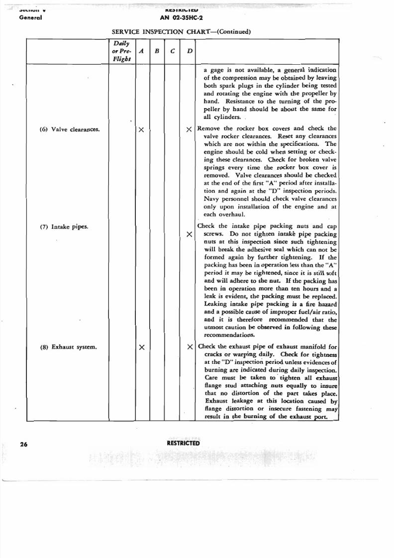
5/11/2018 Wright 2600 - slidepdf.com
http://slidepdf.com/reader/full/wright-2600 35/77
. .~ . ." . . .General
1'l~11'l1"'11aI
AN 02-35HC-2
SERVICE INSPECfION CHART-(Continued)
Dllil]
01' Pre- A
Flight
B c D
26
(6) Valve clearances.
(7) Intake pipes.
(8) Exhaust system.
x
x
a gage is not available, a general indication
of the compression may be obtained by leaving
both spark plugs in the cylinder being tested
and rotating the engine with the propeller by
hand. Resistance to the turning of the pro-
peller by hand should be about the same for
all cylinders. .
X Remove the rocker box covers and check the
valve rocker clearances. Reset any clearances
which are not within the specifications. The
engine should be cold when setting or check-
ing these clearances. Check for broken valve
springs every time the rocker box cover is
removed. Valve clearances should be checked
at the end of the first "A" period after installa-
tion and again at the "0" inspection periods.
Navy personnel should check valve clearances
only upon installation of the engine and at
each overhaul.
Check the intake pipe packing nuts and cap
X screws. Do not tighten intake pipe packing
nuts at this inspection since such tightening
will break the adhesive seal which can not be
formed again by further tightening. If the
packing has been in operation less than the "A"
period it may be tightened, since it is still soft
and will adhere to the nut. If the packing has
been in operation more than ten hours and a
leak is evident, the packing must be replaced.
Leaking intake pipe packing is a fire hazard
and a possible cause of improper fuel/air ratio,
and it is therefore recommended that the
utmost caution be observed in following these
recommendations.
X Check the exhaust pipe of exhaust manifold for
cracks or warping daily. Check for tightness
at the "0" inspection period unless evidences of
burning are indicated during daily inspection.
Care must be taken to' tighten all exhaust
Bange stud attaching nuts equally to insure
that no distortion of the part takes place.
Exhaust leakage at this location caused by
flange distortion or insecure fastening may
result in the burning of the exhaust port.
RESTRICTED
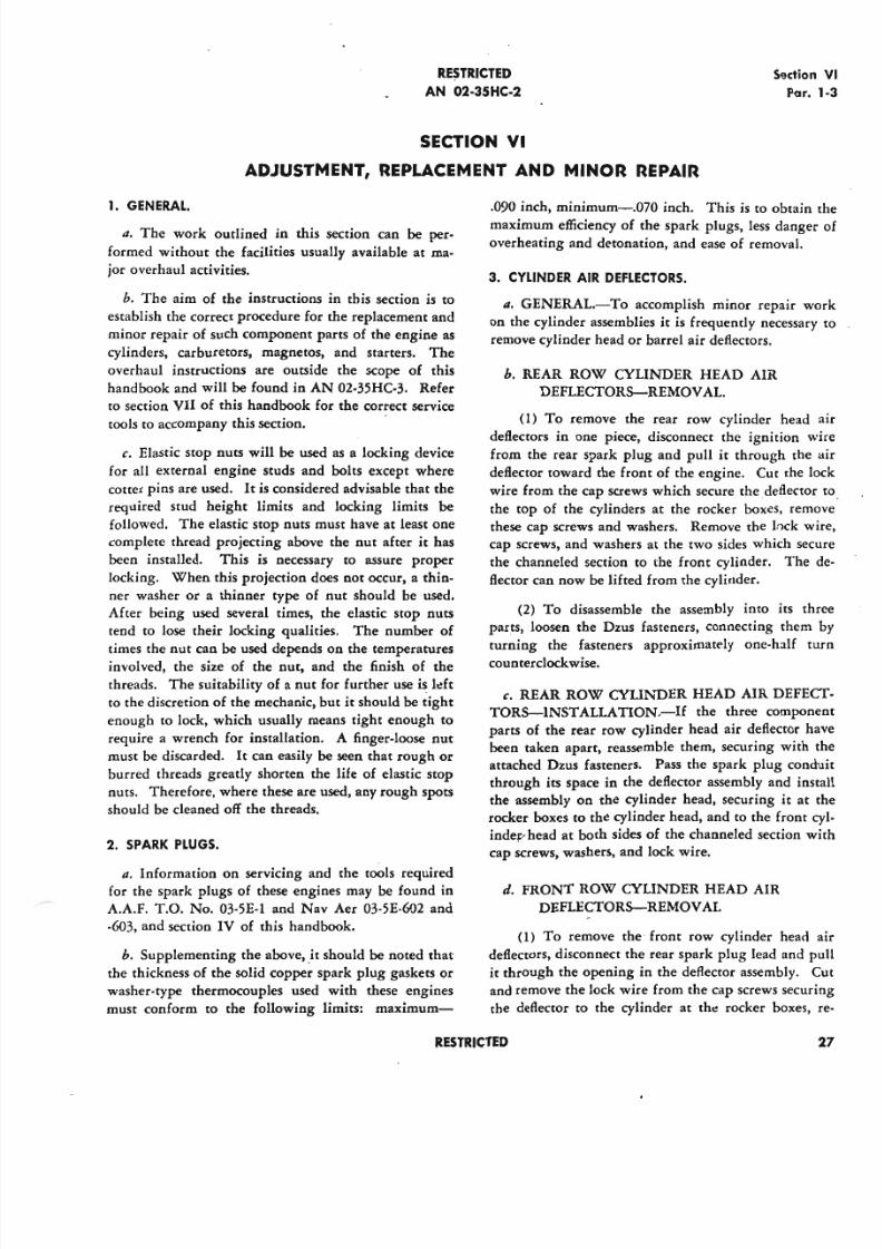
5/11/2018 Wright 2600 - slidepdf.com
http://slidepdf.com/reader/full/wright-2600 36/77
RESTRICTED
AN 02·35HC-2
Sectio
Par
SECTION VI
ADJUSTMENT, REPLACEMENT AND MINOR REPAIR
1. GENERAL.
a. The work outlined in this section can be per-
formed without the facilities usually available at ma-
jor overhaul activities.
h. The aim of the instructions in this section is to
establish the correct procedure for the replacement and
minor repair of such component parts of the engine as
cylinders, carburetors, magnetos, and starters. The
overhaul instructions are outside the scope of this
handbook and will be found in AN 02-35HC-3. Refer
to section VII of this handbook for the correct service
tools to accompany this section.
c. Elastic stop nuts will be used as a locking device
for all external engine studs and bolts except where
cotter pins are used. It is considered advisable that the
required stud height limits and locking limits be
followed. The elastic stop nuts must have at least one
complete thread projecting above the nut after it has
been installed. This is necessary to assure proper
locking. When this projection does not occur, a thin-
ner washer or a thinner type of nut should be used.
After being used several times, the elastic stop nuts
tend to lose their locking qualities. The number of
times the nut can be used depends on the temperaturesinvolved, the size of the nut, and the finish of the
threads. The suitability of a nut for further use is left
to the discretion of the mechanic, but it should be tight
enough to lock, which usually means tight enough to
require a wrench for installation. A finger-loose nut
must be discarded. It can easily be seen that rough or
burred threads greatly shorten the life of elastic stop
nuts. Therefore, where these are used, any rough spots
should be cleaned off the threads.
2. SPARK PLUGS.
a. Information on servicing and the tools required
for the spark plugs of these engines may be found in
A.A.F. T.O. No. 03-5E-l and Nav Aer 03-5E-602 and
-603, and section IV of this handbook.
h. Supplementing the above, _itshould be noted that
the thickness of the solid copper spark plug gaskets or
washer-type thermocouples used with these engines
must conform to the following limits: maximum-
.090 inch, minimum-.070 inch. This is to obtain
maximum efficiency of the spark plugs, less dange
overheating and detonation, and ease of removal.
3. CYLINDER AIR DEFLECTORS.
a. GENERAL.-To accomplish minor repair w
on the cylinder assemblies it is frequently necessar
remove cylinder head or barrel air deflectors.
b. REAR ROW CYLINDER HEAD AIR
DEFLECTORS-REMOVAL.
(1) To remove the rear row cylinder head
deflectors in one piece, disconnect the ignition
from the rear spark plug and pull it through the
deflector toward the front of the engine. Cut the
wire from the cap screws which secure the deflecto
the top of the cylinders at the rocker boxes, rem
these cap screws and washers. Remove the lock
cap screws, and washers at the two sides which se
the channeled section to the front cylinder. The
flector can now be lifted from the cylinder.
(2) To disassemble the assembly into its t
parts, loosen the Dzus fasteners, connecting them
turning the fasteners approximately one-half
counterclockwise.
c. REAR ROW CYLIl'I"DER HEAD AIR DEFE
TORS-INST ALLATION.-If the three compo
parts of the rear row cylinder head air deflector
been taken apart, reassemble them, securing with
attached Dzus fasteners. Pass the spark plug con
through its space in the deflector assembly and in
the assembly on the cylinder head, securing it at
rocker boxes to the cylinder head, and to the front
indee- head at both sides of the channeled section
cap screws, washers, and lock wire.
d. FRONT ROW CYLINDER HEAD AIR
DEFLECTORS-REMOVAL
(1) To remove the front row cylinder head
deflectors, disconnect the rear spark plug lead and
it through the opening in the deflector assembly.
and remove the lock wire from the cap screws secu
the deflector to the cylinder at the: rocker boxes
RESTRICTED
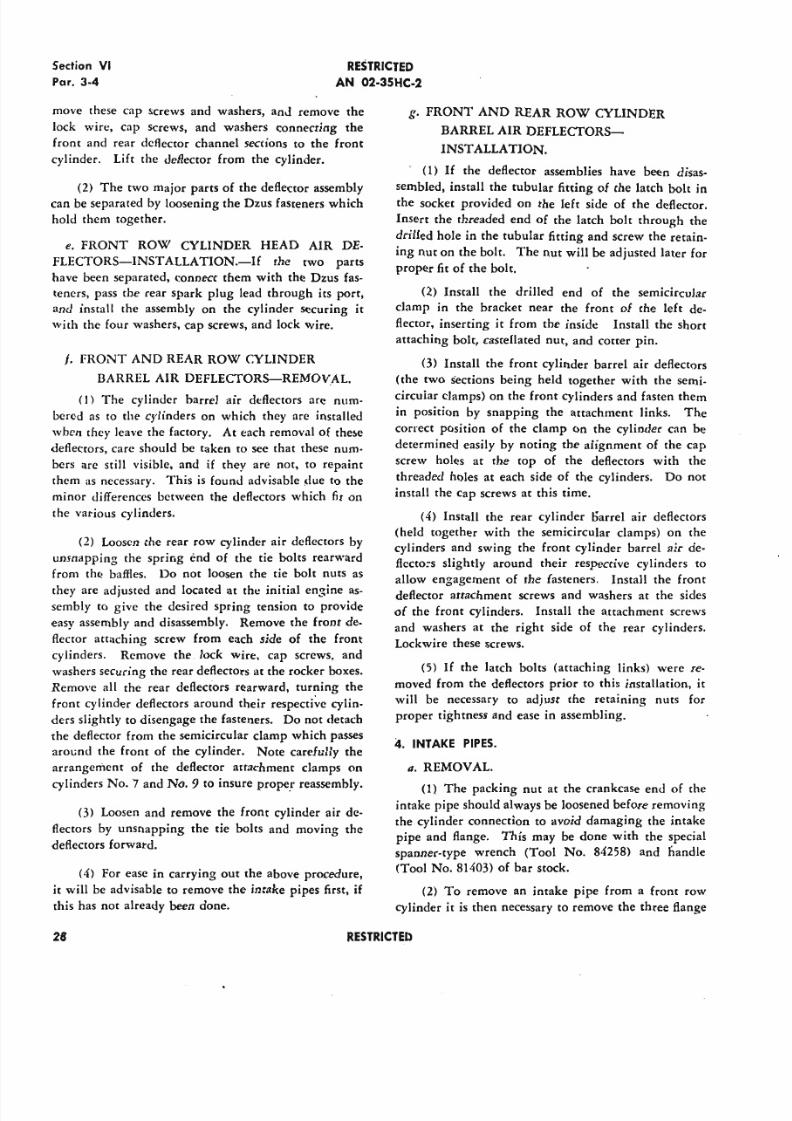
5/11/2018 Wright 2600 - slidepdf.com
http://slidepdf.com/reader/full/wright-2600 37/77
Section VI
Par. 3-4
RESTRICTED
AN 02-35HC-2
move these cap screws and washers, and remove the
lock wire, cap screws, and washers connecting the
front and rear deflector channel sections to the front
cylinder. Lift the deflector from the cylinder.
(2) The two major parts of the deflector assembly
can be separated by loosening the Dzus fasteners which
hold them together.
e. FRONT ROW CYLINDER HEAD AIR DE-
FLECTORS-INSTALLATION.-If the two parts
have been separated, connect them with the Dzus fas-
teners, pass the rear spark plug lead tbrough its port,
and install the assembly on the cylinder securing it
with the four washers, cap screws, and lock wire.
t. FRONT AND REAR ROW CYLINDER
BARREL AIR DEFLECTORS-REMOVAL.
<I) The cylinder barrel air deflectors are num-
bered as to the cylinders on which they arc installed
when they leave the factory. At each removal of these
deflectors, care should be taken to see that these num-
bers are still visible. and if they are not, to repaint
them as necessary. This is found advisable due to the
minor differences between the deflectors which fit on
the various cylinders.
(2) Loosen the rear row cylinder air deflectors by
unsnapping the spring end of the tie bolts rearward
from the baffles. Do not loosen the tie bolt nuts as
they are adjusted and located at the initial engine as-
sembly to give the desired spring tension to provide
easy assembly and disassembly. Remove the front de-
flector attaching screw from each side of the front
cylinders. Remove the lock wire. cap screws, and
washers securing the rear deflectors at the rocker boxes.
Remove all the rear deflectors rearward, turning the
front cylinder deflectors around their respective cylin-
ders slightly to disengage the fasteners. Do not detach
the deflector from the semicircular clamp which passes
around the front of the cylinder. Note carefully the
arrangement of the deflector attachment clamps on
cylinders No.7 and No.9 to insure prope.r reassembly.
(3) Loosen and remove the front cylinder air de-
flectors by unsnapping the tie bolts and moving the
deflectors forward.
(4) For ease in carrying out the above procedure,
it will be advisable to remove the intake pipes first, if
this has not already been done.
28
g. FRONT AND REAR ROW CYLINDER
BARREL AIR DEFLECTORS-
INST ALLATION.
(1) If the deflector assemblies have been disas-
sembled, install the tubular fitting of the latch bolt in
the socket provided on the left side of the deflector.
Insert the threaded end of the latch bolt through the
drilled hole in the tubular fitting and screw the retain-
ing nut on the bolt. The nut will be adjusted later for
proper fit of the bolt.
(2) Install the drilled end of the semicircular
clamp in the bracket near the front of the left de-
flector, inserting it from the inside Install the short
attaching bolt, castellated nut, and cotter pin.
(3) Install the front cylinder barrel air deflectors
(the two sections being held together with the semi-
circular clamps) on the front cylinders and fasten them
in position by snapping the attachment links. The
correct position of the clamp on the cylinder can be
determined easily by noting the alignment of the cap
screw holes at the top of the deflectors with the
threaded holes at each side of the cylinders. Do not
install the cap screws at this time.
(4) Install the rear cylinder !Jarre! air deflectors
(held together with the semicircular clamps) on the
cylinders and swing the front cylinder barrel air de-
flecrors slightly around their respective cylinders to
allow engagement of the fasteners. Install the front
deflector attachment screws and washers at the sides
of the front cylinders. Install the attachment screws
and washers at the right side of the rear cylinders.
Lockwire these screws.
(5) If the latch bolts (attaching links) were re-
moved from the deflectors prior to this installation, it
will be necessary to adjust the retaining nuts for
proper tightness and ease in assembling.
4. INTAKE PIPES.
a. REMOVAL.
(1) The packing nut at the crankcase end of (he
intake pipe should always be loosened before removing
the cylinder connection to avoid damaging the intake
pipe and flange. This may be done with the special
spanner-type wrench (Tool No. 84258) and handle
<Tool No. 81403) of bar stock.
(2) To remove an intake pipe from a front row
cylinder it is then necessary to remove the three flange
RESTRICTED
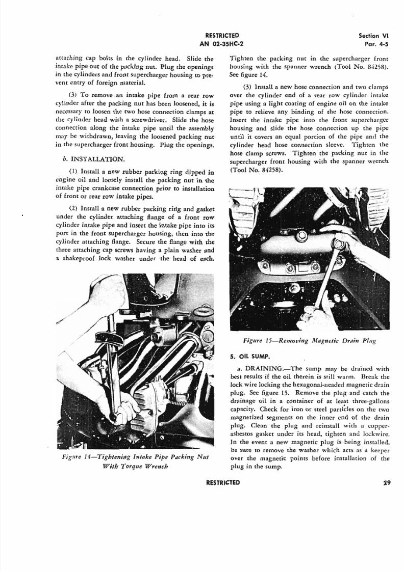
5/11/2018 Wright 2600 - slidepdf.com
http://slidepdf.com/reader/full/wright-2600 38/77
RESTRICTED
AN 02·35HC·2
Sect
P
attaching cap bolts in the cylinder head. Slide the
intake pipe out of the packing nut. Plug the openings
in the cylinders and front supercharger housing to pre.
vent entry of foreign material.
(3) To remove an intake pipe from a rear row
cylinder after the packing nut has been loosened, it is
necessary to loosen the two hose connection clamps at
the cylinder head with a screwdriver. Slide the hose
connection along the intake pipe until the assembly
may be withdrawn, leaving the loosened packing nut
in the supercharger front housing. Plug the openings.
b. INSTALLATION.
(I) Install a new rubber packing ring dipped in
engine oil and loosely install the packing nut in the
intake pipe crankcase connection prior to installation
of front or rear row intake pipes.
(2) Install a new rubber packing ring and gasket
under the cylinder attaching flange of a front row
cylinder intake pipe and insert the intake pipe into its
port in the front supercharger housing, then into the
cylinder attaching flange. Secure the flange with the
three attaching cap screws having a plain washer and
a shakeproof lock washer under the head of each.
Figure 14-Tighlening Intake Pipe Packing NIII
Wilh Torque Wrench
Tighten the packing nut ID the supercharger
housing with the spanner wrench (Tool No. 8
See figure 14.
(3) Install a new hose connection and two
over the cylinder end of a rear row cylinder
pipe using a light coating of engine oil on the
pipe to relieve any binding of the hose conne
Insert the intake pipe into the front superch
housing and slide the hose connection up the
until it covers an equal portion of the pipe a
cylinder head hose connection sleeve. Tighten
hose clamp screws. Tighten the packing nut
supercharger front housing with the spanner w
(Tool No. 84258).
Figure 15-Removing Magnetic Drain Plu
5. OIL SUMP.
a. DRAINING.-The sump may be drained
best results if the oil therein is still warm. Bre
lock wire locking the hexagonal-ueaded magnetic
plug. See figure 15. Remove the plug and ca
drainage oil in a container of at least three-g
capacity. Check for iron or steel particles on t
magnetized segments on the inner end of the
plug. Clean the plug and reinstall with a
asbestos gasket under its head, tighten and lo
In the event a new magnetic plug is being in
be sure to remove the washer which acts as a
over the magnetic points before installation
plug in the sump.
RESTRICTED
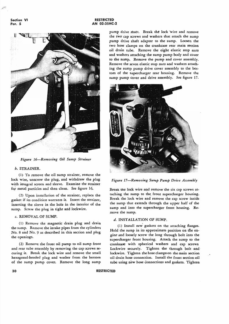
5/11/2018 Wright 2600 - slidepdf.com
http://slidepdf.com/reader/full/wright-2600 39/77
Sedion V IPar. 5
RESTRICTED
AN 02'-35HC-2
Figure 16-Removing Oil Sump Strainer
b. STRAINER.
(1) To remove the oil sump strainer, remove the
lock wire, unscrew the plug, and withdraw the plug
with integral screen and sleeve. Examine the strainer
for metal particles and then clean. See figure 16.
(2) Upon installation of the strainer, replace the
gasket if its condition warrants it. Insert the strainer,
inserting the sleeve in the hole in the interior of the
sump. Screw the plug in tight arid lockwire.
c. REMOVAL OF SUMP.
(1) Remove the magnetic drain plug and drain
the sump. Remove the intake pipes from the cylinders
No. 8 and No.9 as described in this section and plug
the openings.
(2) Remove the front oil pump to oil sump front
and rear tube assembly by removing the cap screws se-
curing it. Break the lock wire and remove the small
hexagonal-headed plug and washer from the bottom
of the sump pump cover. Remove the long sump
30
pump drive snarr, Break the lock 'wire and remove
the rwo cap screws and washers that attach the sump
pump drive shaft adapter to the sump. Loosen the
two hose clamps on the crankcase rear main section
oil drain tube. Remove the eight elastic stop nuts
and washers attaching the sump pump body and coverto the sump. Remove the pump and cover assembly.
Remove the seven elastic stop nuts and washers attach-
ing the sump pump drive cover assembly to the bot-
tom of the supercharger rear housing. Remove the
sump pump cover and drive assembly. See figure 17.
Figure I7-Removing Sump Pump Drive Assembly
Break tne lock wire and removethe six cap screws at-
taching the sump to the, front supercharger housing.
Break the lock wire and remove the cap screw inside
the sump that extends through the upper half of the
sump and into the supercharger front housing. Re-
move the sump.
d. INSTALLATION OF SUMP.
(I) Install new gaskets on the attaching flanges.Hold the sump in its approximate position on tFie en-
gine and loosely screw the long through bolt into the
supercharger front housing. Attach the sump to the
crankcase with spherical washers and cap screws
Lockwire securely. Tighten the through bolt and
lockwire. Tighten the hose clamps on the main section
oil drain hose connection. Install the front section-oil
tube using new hose connections and gaskets. Tighten
"
RESTRICTED
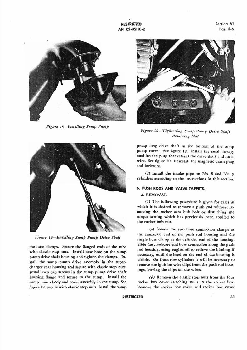
5/11/2018 Wright 2600 - slidepdf.com
http://slidepdf.com/reader/full/wright-2600 40/77
R E S T R I C T E D
AN 02-35HC-2
Figure IB-1nstalling Slimp Pump
Figure I9-Jnstalling Sump Pllmp Drive Shafl
the hose damps. Secure the flanged ends of the tube
with elastic stop nuts. Install new hose on the sump
pump drive shaft housing and tighten the clamps. In-
stall the sump pump drive assembly in the super-
charger rear housing and secure with elastic stop nuts.
Install two cap screws in the sump pump drive shaft
housing flange and secure to the sump. Install the
sump pump body and cover assembly in the sump. See
figure 18. Secure with elastic stop nuts. Install the sump
Section
Par.
Figure 20-Tightening Slimp Pum]» Driue Sba
Retaining Nut
pump long drive shaft in the bottom of the s
pump cover. See figure 19. Install the small he
onal-headed plug that retains the drive shaft and
wire. See figure 20. Reinstall the magnetic drain
and lockwire.
(2) Install the intake pipe on No, 8 and N
cylinders according to the instructions in this sec
6. PU SH RO DS AND V A LV E T A PPE TS .
a. REMOVAL.
(1) The following procedure is given for cas
which it is desired to remove a push rod without
moving the rocker arm hub bolt or disturbing
torque setting which has previously been applie
the rocker bolt nut.
(a) Loosen the two hose connection damp
the crankcase end of the pusb rod bousing and
single hose clamp at the cylinder end of the hou
Slide the crankcase end hose connection along the
rod housing, using engine oil to relieve the bindin
necessary, until the bead on the end of the housin
visible. On front row cylinders it will be necessa
remove the ignition wire clips from the push rod
ings, leaving the dips on the wires.
(b) Remove the elastic stop nuts from the
rocker box cover attaching studs in the rocker
Remove the rocker box cover and rocker box
R E S T R I C T E D
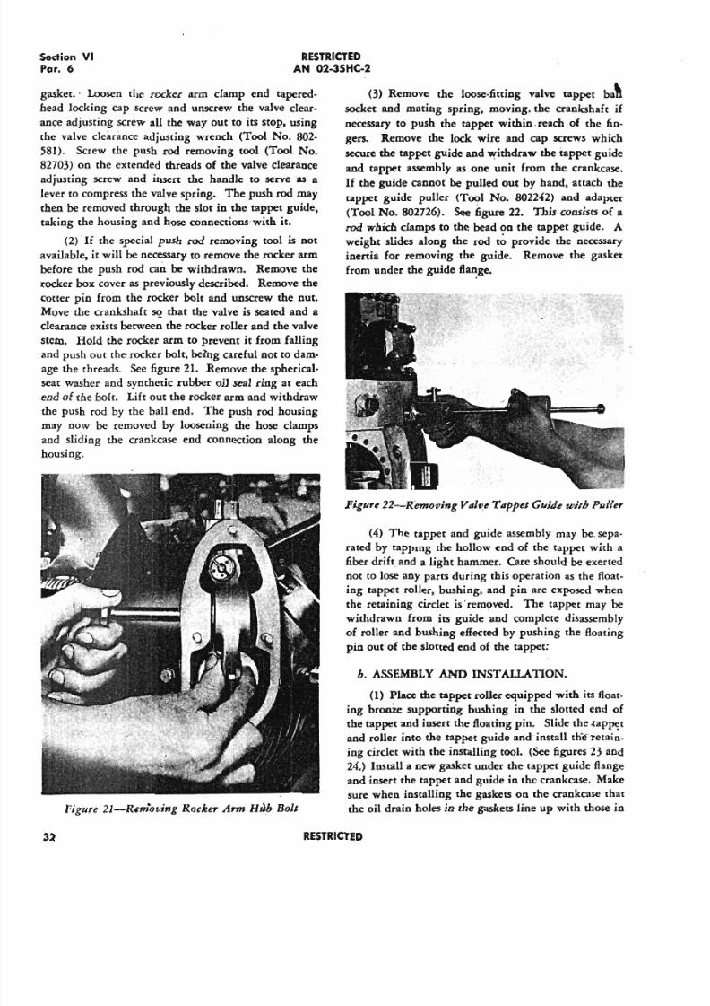
5/11/2018 Wright 2600 - slidepdf.com
http://slidepdf.com/reader/full/wright-2600 41/77
RESTRICTED
AN 02-35HC-2
(3) Remove the loose-fitting valve tappet ba~
socket and mating spring, moving. the crankshaft if
necessary to push the tappet within. reach of the fin-
gers. Remove the lock wire and cap screws which
secure the tappet guide and withdraw the tappet guide
and tappet assembly as one unit from the crankcase.
If the guide cannot be pulled out by hand, attach the
tappet guide puller (Tool No. 802242) and adapter
(Tool No. 802726)_ See f i g u r e 22. This consists of a
rod which clamps to the bead ?n the tappet guide. A
weight slides along the rod to provide the necessary
inertia for removing the guide. Remove the gasket
from under the guide fI~ge.
Section V I
Par. 6
gasket.· Loosen the rocker arm clamp end tapered-
head locking cap screw and unscrew the valve clear-
ance adjusting screw all the way out to its stop, using
the valve clearance adjusting wrench (Tool No. 802-
581). Screw the push rod removing tool (Tool No.
82703) on the extended threads of the valve clearance
adjusting screw and insert the handle to serve as a
lever to compress the valve spring. The push rod may
then be removed through the slot in the tappet guide,
taking the housing and hose connections- with it.
(2) If the special push rod removing tool is not
available, it will be necessary to remove the rocker arm
before the push rod can be withdrawn. Remove the
rocker box cover as previously described. Remove the
cotter pin from the rocker bolt and unscrew the nut.
Move the crankshaft ~ that the valve is seated and a
clearance exists between the rocker roller and the valve
stem. Hold the rocker arm to prevent it from falling
and push out the rocker bolt, being careful not to dam.
age the tbreads. See figure 21. Remove the spherical.
seat washer and synthetic rubber oil seal ring at each
end of tbe bolt. Lift out the rocker arm and withdraw
the push rod by rhe ball end. The push rod housing
may now be removed by loosening the hose clamps
and sliding the crankcase end connection along the
housing.
Figure 22-Removing Valv.eTappet Guide with Puller
(4) The tappet and guide assembly may be. sepa-
rated by tappmg the hollow end of the tappet with a
fiber drift and a light hammer. Care should be exerted
not to lose any parts during this operation as the float-
ing tappet roller, bushing, and pin are exposed wben
the retaining circlet is "removed. The tappet may be
withdrawn from its guide and complete disassembly
of roller and bushing effected by pushing the floating
pin out of the slotted end of the tappet:
b. ASSEMBLY AND INSTAllATION.
(1) Place the tappet roller equipped with its float-
ing bronze supporting bushing in the slotted end of
the tappet and insert the floating pin. Slide the .tap~t
and roller into the tappet guide and install the-retain-
ing circlet with the installing tool. (See figures 23 and
24.) Install a new gasket under the tappet guide flange
and insert the tappet and guide in the crankcase. Make
sure when installing the gaskets on the crankcase that
Figure 21-Rem'oving Rocker Arm Hab Bolt the oil drain boles in the gaskets line up with those in
32 RESTRICTED
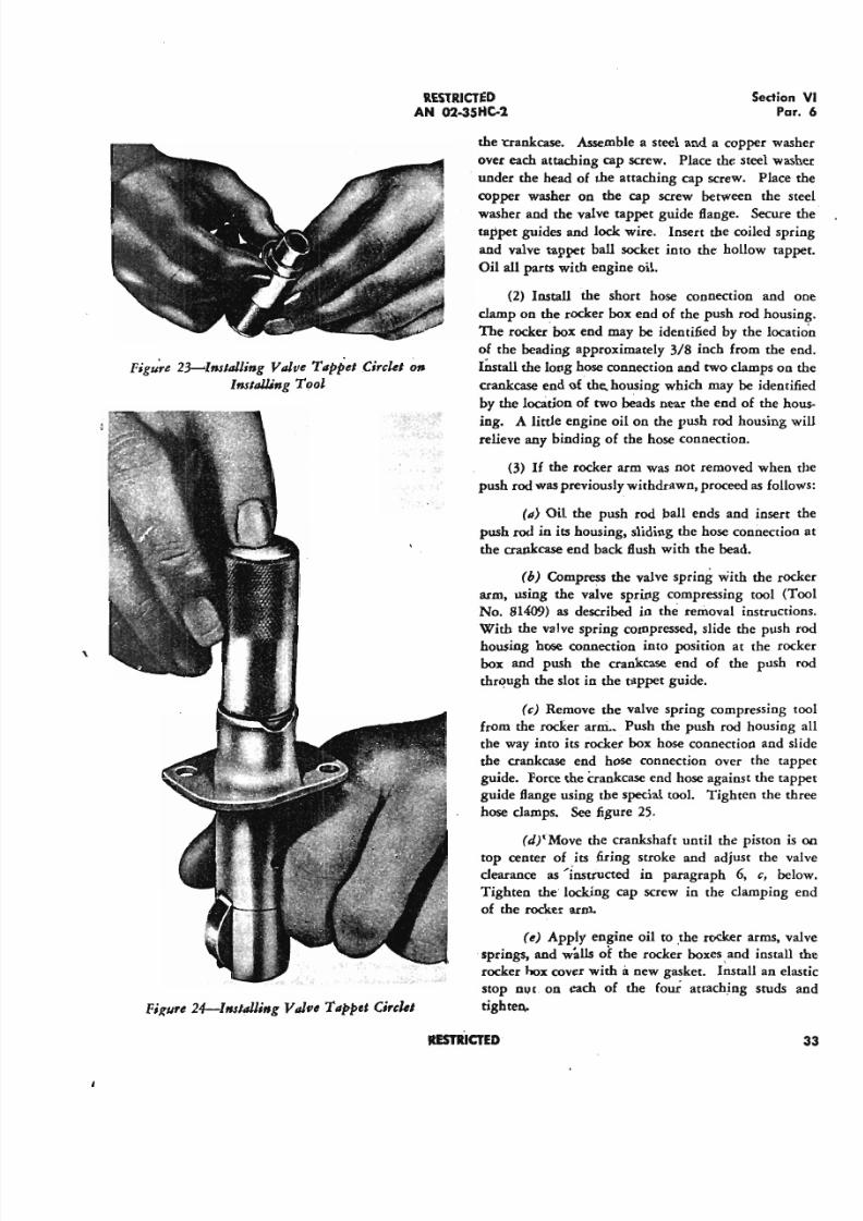
5/11/2018 Wright 2600 - slidepdf.com
http://slidepdf.com/reader/full/wright-2600 42/77
RESTRICTED
AN 02-35HC-2Sedion
Pa
Figu~e 2~Inslalling Valve Tappet Circlet 01J
InslalJ,;ng Tool
,
FiKure 24-Inslalliflg V JfJe Tappet eirckl
the nankcase. Assemble a steel and a copper wa
over each attaching cap screw. Place the steel wa
. under the head of the attaching cap screw. Place
copper washer on the cap screw between the
washer and the valve tappet guide Bange. Secure
tappet guides and lock wire. Insert the coiled sp
and valve tappet ball socket into the hollow tap
Oil all parts with engine oil.
(2) Install the short hose connection and
clamp on the rocker box end of the push rod hous
The rocker· box end may be identified by the loca
of the beading approximately 3/8 inch from the
IOstau the long hose connection and two clamps on
crankcase end of the, housing which may be identi
by the location of two beads near the end of the h
ing. A little engine oil on the push rod housingrelieve any binding of the hose connection.
(3) If the rocker arm was not removed when
push rod was previously withdrawn, proceed as foll
(a) Oil the push rod ball ends and insert
push rod in its housing, sliding the hose connectio
the crankcase end back Bush with the bead.
(b) Compress the valve spring with the ro
arm, using the valve spring compressing tool (
No. 814(9) as described in the removal instructi
With the valve spring compressed, slide the push
housing hose connection into position at the ro
box and push the crankcase end of the push
through the slot in the tappet guide.
(c) Remove the valve spring compressing
from the rocker arm., Push the push rod housing
the way into its rocker box hose connection and
the crankcase end hose connection over the ta
guide. Force the crankcase end hose against the ta
guide flange using the special tool. Tighten the t
hose clamps. See figure 25.
(J;tMove the crankshaft until the piston
top center of its firing stroke and adjust the v
clearance as'instructed in paragraph 6, c, be
Tighten the locking cap screw in the clamping
of the rocker arm.
(e) App1y engine oil to the rocker arms. v
springs, and walls of the rocker boxes, and install
rocker hox cover with it new gasket. Install an el
stop nut on each of the four attaching studs
tighten,
RESTRICTED
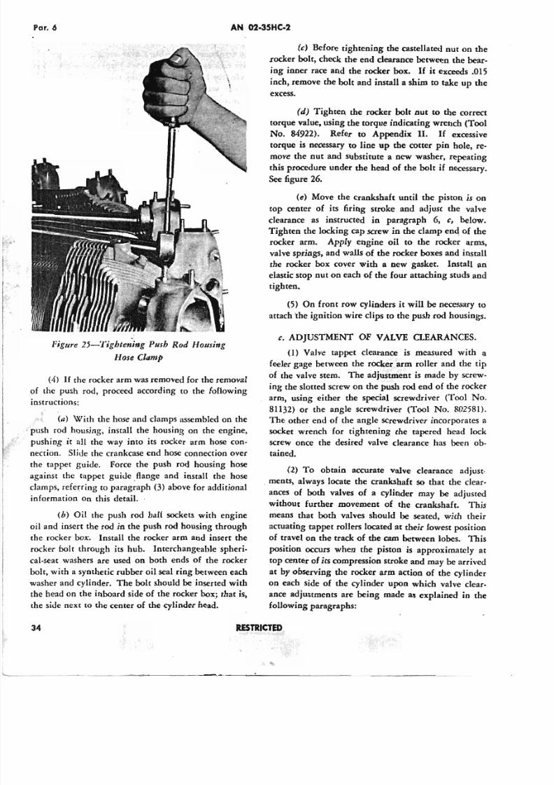
5/11/2018 Wright 2600 - slidepdf.com
http://slidepdf.com/reader/full/wright-2600 43/77
Par. 6 AN 02-35HC-2
. . -
II
f' .~. . .'
Figure 25-Tjghtening Push Rod Housing
Hose Clamp
(4) If the rocker arm was removed for the removal
of the push rod, proceed according to the following
instructions:
(0) With the hose and clamps assembled on the
push rod housing, install the housing on the engine,
pushing it all the way into its rocker arm hose con"
nection. Slide the crankcase end hose connection over
the tappet guide. Force the push rod housing hose
against the tappet guide. flange and install the hose
damps, referring to paragraph (3) above for additional
information on this detail.
(b) Oil the push rod ball sockets with engine
oil and insert the rod in the push rod housing through
the rocker box. Install the rocker arm and insert the
rocker bolt through its hub. Interchangeable spheri-
cal-seat washers are used on both ends of the rocker
bolt, with a synthetic rubber oil seal ring between each
washer and cylinder. The bolt should be inserted with
the head on the inboard side of the rocker box; that is,
the side next to the center of the cylinder head.
34
(c) Before tightening the castellated nut on the
.rocker bolt, check the end clearance between the bear-
ing inner race and the rocker box. If it exceeds .015
inch, remove the bolt and install a shim to take up the
excess.
(d) Tighten the rocker bolt nut to the correct
torque value, using the torque indicating wrench (Tool
No. 84922). Refer to Appendix II. If excessivetorque is necessary to line up the cotter pin hole, re-
move the nut and substitute a new washer, repeating
this procedure under the head of the bolt if necessary.
See figure 26.
(e) Move the crankshaft until the piston is on
top center of its firing stroke and adjust the valve
clearance as instructed in paragraph 6, c, below.
Tighten the locking cap screw in the clamp end of the
rocker arm. Apply engine oil to the rocker arms,
valve springs, and walls of the rocker boxes and install
the rocker box cover with a new gasket. Install an
elastic stop nut on each of the four attaching studs and
tighten.
(5) On front row cylinders it will be necessary to
attach 'the ignition wire clips to the push rod housings.
c. ADJUSTMENT OF VALVE CLEARANCES.
(1) Valve tappet clearance is measured with a
feeler gage between the rocker arm roller and the tip
of the valve stem. The adjustment is made by screw-
ing the slotted screw on the push rod end of the rocker
arm, using either the special screwdriver (Tool No.
81132) or the angle screwdriver (Tool No. 802581).The other end of the angle screwdriver incorporates a
socket wrench for tightening the tapered head lock
screw once the desired valve clearance has been ob-
tained.
(2) To obtain accurate valve clearance adjust-
. rnents, always locate the crankshaft so that the clear-
ances of both valves of a cylinder may be adjusted
without further movement of the crankshaft. This
means that both valves should be seated, with their
actuating tappet rollers located at their lowest position
of travel on the track of the cam between lobes. This
position occurs when the piston is approximately at
top center of its compression stroke and may be arrived
at by observing the rocker arm action of the cylinder
on each side of the cylinder upon which valve clear-
ance adjustments are being made as explained 10 the
following paragraphs:
R E S T R I C T E D
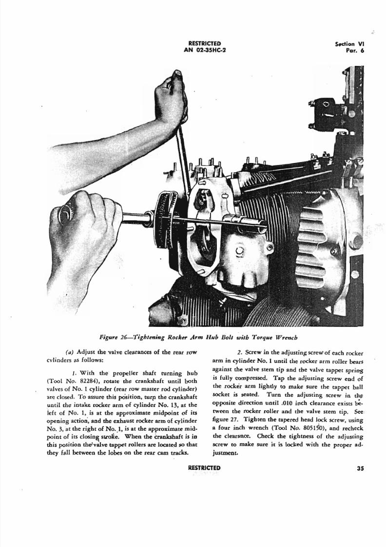
5/11/2018 Wright 2600 - slidepdf.com
http://slidepdf.com/reader/full/wright-2600 44/77
RESTRICTED
AN 02-35Ht-2Section
Pa
Figure 26-Tighlening Rocker Arm Hub Boll wilh Torque Wrench
(a) Adjust the valve clearances of the rear row
CYlinders as follows:
1. With the propeller shaft turning hub
(Tool No. 82284), rotate the crankshaft until bothvalves of No.1 cylinder (rear row master rod cylinder)
are closed. To assure this position, turp the crankshaft
until the intake rocker arm of cylinder No. 13, at the
left of No.1, is at the approximate midpoint of its
opening action, and the exhaust rocker arm of cylinder
No. 3, at the right of No. _I , is at the approximate mid-
point of its closin& st.ro1ie. When the Crankshaft is in
this position the'valve tappet rollers are located so that
they fall between the lobes on the rear cam tracks,
2. Screw in the adjusting screw of each roc
arm in cylinder No.1 until the rocker arm roller b
against the valve stem tip and the valve tappet spr
is fully compressed. Tap the adjusting screw end
the .rocker arm lightly to make sure the tappet
socket is seated. Turn the adjusting screw in
opposite direction until .010 inch clearance exists
tween the rocker roller and the valve stem tip.
figure 27. Tighten the tapered head lock screw, us
a four inch wrench (Tool No. 8051~O), and rech
the clearance. Check the tightness of the adjust
screw to make sure it is locked with the proper
justment.
RESTRICTED
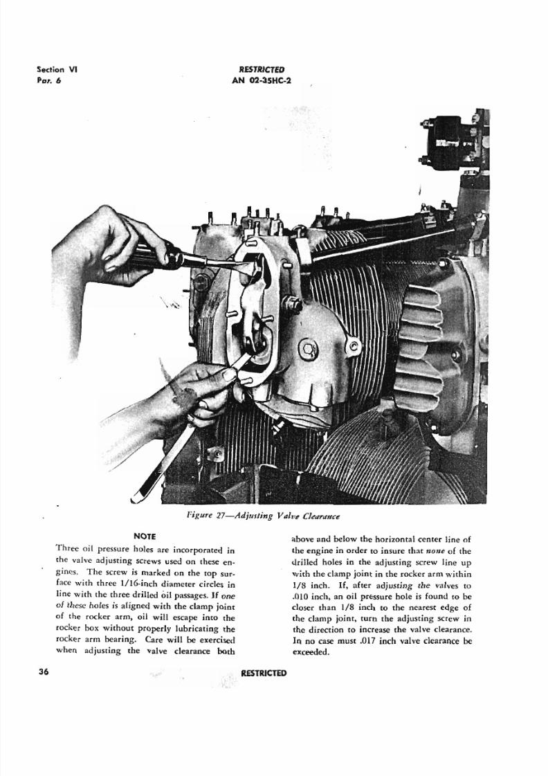
5/11/2018 Wright 2600 - slidepdf.com
http://slidepdf.com/reader/full/wright-2600 45/77
Section VI
Par. 6
RESTRICTED
AN 02-35HC-2
Figure 27-Adjusting ValvI! Clearance
NOTE
Three oil pressure holes are incorporated in
the valve adjusting screws used on these en-
gines. The Screw is marked on the top sur-
face with three 1/16-inch diameter circles in
line with the three drilled oil passages. If one
of these holes is aligned with the clamp joint
of the rocker arm, oil will escape into the
rocker box without properly lubricating the
rocker arm bearing. Care will be exercised
when adjusting the valve clearance both
above and below the horizontal center line of
the engine in order to insure that n011eof the
drilled holes in the adjusting screw line up
with the clamp joint in the rocker arm within
1/8 inch. If, after adjusting the valves to
.010 inch, an oil pressure hole is found to be
closer than 1/8 inch to the nearest edge of
the clamp joint, turn the adjusting screw in
the direction to increase the valve clearance.
In no case must .017 inch valve clearance be
exceeded.
36 RESTRICTED
~.
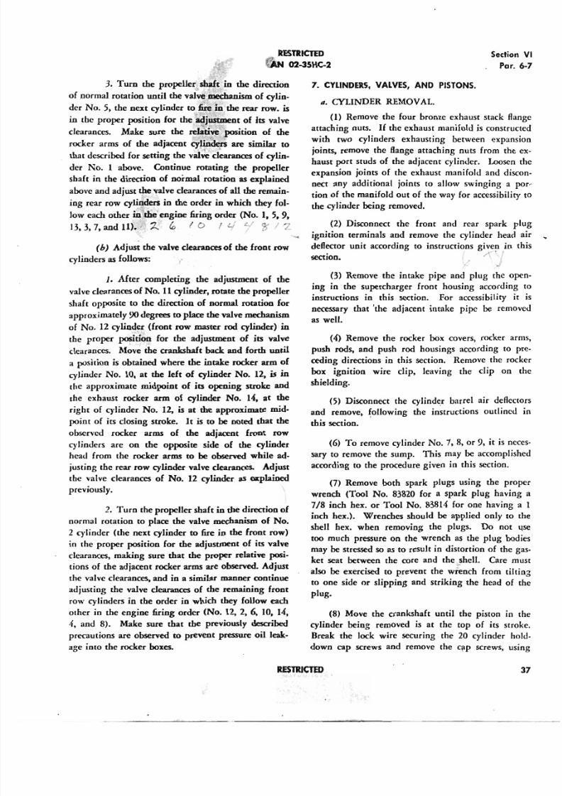
5/11/2018 Wright 2600 - slidepdf.com
http://slidepdf.com/reader/full/wright-2600 46/77
RESTRICTED
do . 02-35HC-2
3. Tum the propeller' shaft in the direction
of normal rotation until the valve ~anism of cylin-
der No.5, the next cylinder to fire in the rear row. is
in the proper position for the adjustment of its valve
clearances. Make sure the re~'\ive ,position of the
rocker arms of the adjacent cywide,rs are similar to
that described for setting the val~'dearances of cylin-
der No. 1 above. Continue rotating the propeller
shaft in the direction of normal rotation as explained
above and adjust the valve clearances of all the remain-
ing rear row cylinders in the order in which they fol-
low each other ~ the' engine firing order (No.1. 5. 9.
13, 3, 7. and 11).' z, ~ (0 I '-/ L/ ?r / "2 .
(bJ Adjust the valve clearances of the front row
cylinders as follows: ,.
1. After completing the adjustment of the
valve clearances of No. 11 cylinder. rotate the propeller
shaft opposite to the direction of normal rotation for
approximately 90 degrees to place the valve mechanism
of No. 12 cylind~r (front row master rod cylinder) in
the proper position for the adjustment of its valve
clearances. Move the crankshaft back and forth until
a position is obtained where the intake rocker arm of
cylinder No. 10, at the left of cylinder No. 12, is in
the approximate midpoint of its opening stroke and
the exhaust rocker arm of cylinder No. 14. at the
rigbt of cylinder No. 12, is at the approximate mid-
point of its closing stroke. It is to be noted that the
observed rocker arms of the adjacent front row
cylinders are on the opposite side of the cylinder
head from the rocker arms to be observed while ad-
justing the rear row cylinder valve clearances, Adjust
rhe valve clearances of No. 12 cylinder as CoIplained
previously.
2. Tum the propeller shaft in the direction of
normal rotation to place the valve mechanism of No.
2 cylinder (the next cylinder to fire in the front row)
in the proper position for the adjustment of its valve
clearances. making sure that the proper relative posi-tions of the adjacent rocker arms are observed. Adjust
the valve clearances, and in a similar manner continue
adjusting the valve clearances of the remaining front
row cylinders in the order in which they follow each
other in the engine firing order (No. 12, 2. 6. 10. 14.
4. and 8). Make sure that the previously described
precautions are observed to prevent pressure oil leak-
age into the rocker boxes.
Section
Par
7. CYLINDERS, VALVES, AND PISTONS.
II. CYLINDER REMOVAL.
(1) Remove the four bronze exhaust stack fl
attaching nuts. If the exhaust manifold is constru
with two cylinders exhausting between expan
joints, remove the flange attaching nuts from the
haust port studs of the adjacent cylinder. Loosen
expansion joints of the exhaust manifold and dis
nect any additional joints to allow swinging a
tion of the manifold out of the way for accessibilit
the cylinder being removed.
(2) Disconnect the front and rear spark
ignition terminals and remove the cylinder head
deflector unit according to instructions given in
section. I.: ,;'()
(3) Remove the intake pipe and plug the oing in the supercharger front housing according
instructions in this section. For accessibility
necessary that 'the adjacent intake pipe be remo
as well.
(4) Remove the rocker box covers, rocker a
push rods. and push rod housings according to
ceding directions in this section. Remove the ro
box ignition wire dip, leaving the dip on
shielding.
(5) Disconnect the cylinder barrel air defle
and remove, following the instructions outlined
this section.
(6) To remove cylinder No.7, 8, or 9, it is n
sary to remove the sump. This may be accomplis
according to the procedure given in this section.
(7) Remove both spark plugs using the pro
wrench (Tool No. 83820 for a spark plug havin
7/8 inch hex. or Tool No. 83814 for one having
inch hex.), Wrenches should be applied only to
shell hex. when removing the plugs. Do not
too much pressure on the wrench as the plug bo
may be stressed so as to result in distortion of the
ket seat between the core and the shell. Care m
also be exercised to prevent the wrench from til
to one side or slipping and striking the head of
plug.
(8) Move the crankshaft until the piston in
cylinder being removed is at the top of its str
Break the lock wire securing the 20 cylinder h
down cap screws and remove the qlp screws, u
RESTRICTED
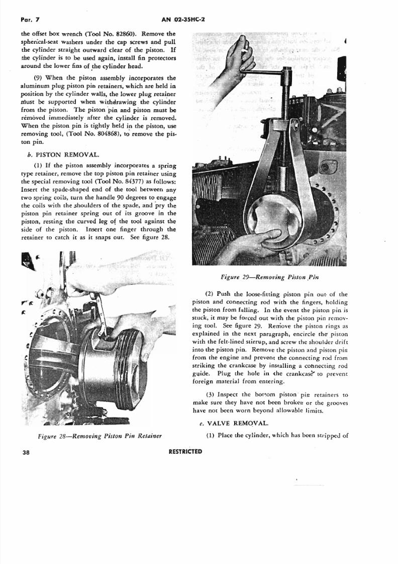
5/11/2018 Wright 2600 - slidepdf.com
http://slidepdf.com/reader/full/wright-2600 47/77
Par. 7 AN .02-35HC-2
the offset box wrench (Tool No. 82860). Remove the
spherical-seat washers under the cap screws and pull
the cylinder straight outward clear of the piston. If
the cylinder is to be used again, install fin protectors
around the lower fins of _thecylinder head.
(9) When the piston assembly incorporates the
aluminum plug piston pin retainers, which are held in
position by the cylinder walls, the lower plug retainer
must be supported when withdrawing the cylinder
from the piston. The piston 'pin and piston must be
removed immediately after the cylinder is removed.
When the piston pin is tightly held i~ the piston, use
removing tool, (Tool No. 804868), to remove the pis-
ton pin.
h. PISTON REMOVAL.
(1) If the piston assembly incorporates a spring
type retainer, remove the top piston pin retainer using
the special removing tool (Tool No. 84377) as follows:
Insert the spade-shaped end of the tool between any
two spring coils, turn the handle 90 degrees to engage
the coils with the shoulders of the spade, and pry the
piston pin retainer spring out of its groove in the
piston, resting the curved leg of the tool against the
side of the piston. Insert one finger through the
retainer to catch it as it snaps out. See figure 28.
Figure 29-Removing Piston .Pin
(2) Push the loose-fitting piston pin out of thepiston and connecting rod with the fingers, holding
the piston from falling. In the event the piston pin is
stuck, it may be forced out with the piston pin remov-
ing tool. See figure 29. Remove the piston rings as
explained in the next paragraph; encircle the .piston
with the felt-lined stirrup, and screw the shoulder drift
into the piston pin. Remove the piston and piston pin
from the engine and prevent the connecting rod from
striking the crankcase by installing a connecting rod
guide. Plug the hole in (he crankcase" to prevent
foreign material from entering.
(3) Inspect the bottom piston' pin retainers to
make sure they have not been broken or the grooves
have not been worn beyond allowable limits.
Figure 28-Removing Piston Pin Retainer (1) Place the cylinder, which has been stripped of
c. VALVE REMOVAL.
38 RESTRICTED
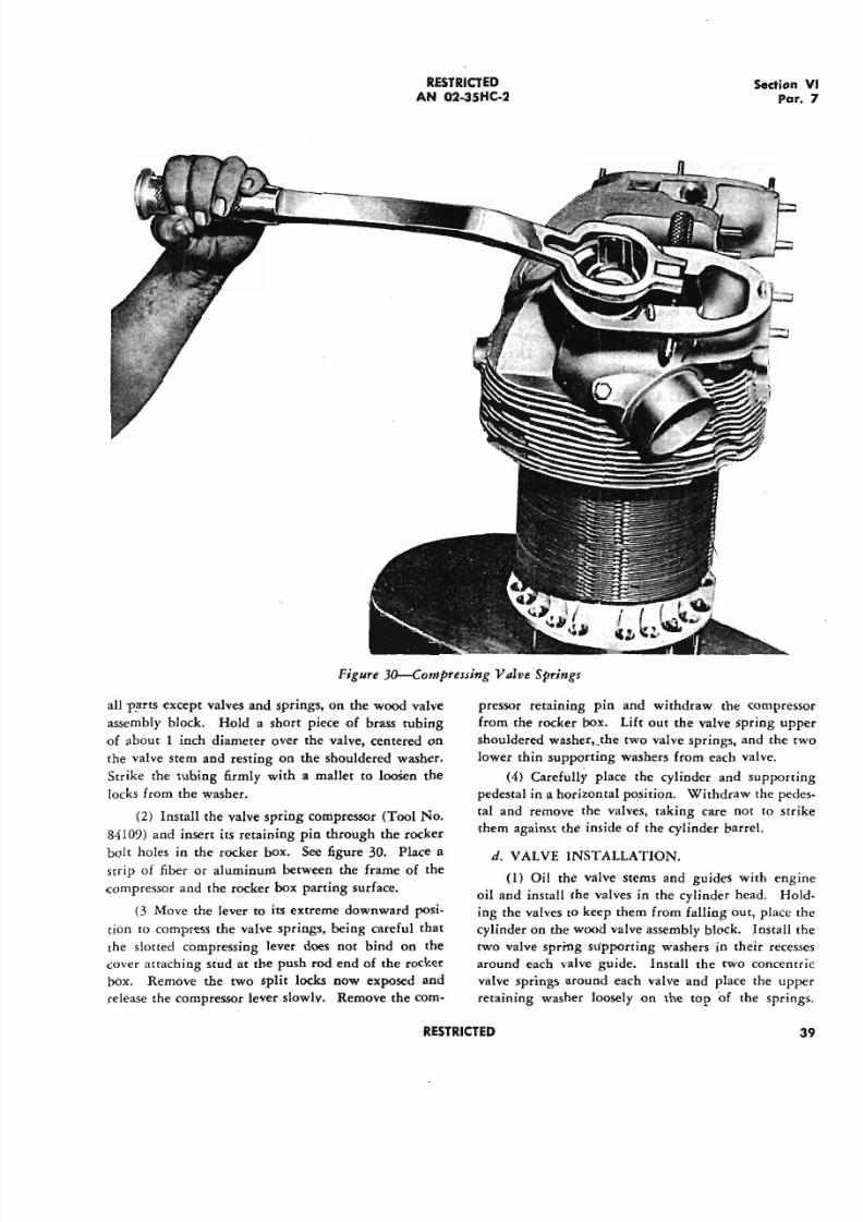
5/11/2018 Wright 2600 - slidepdf.com
http://slidepdf.com/reader/full/wright-2600 48/77
R E S T R I C T E D
AN 02-35HC-2·Sedio
P
Figure 3~ompressing Valve Springs
all p~t5 except valves and springs, on the wood valve
assembly block. Hold a short piece of brass tubing
of about 1 inch diameter over the valve, centered on
the valve stem and resting on the shouldered washer.
Strike the tubing firmly with a mallet to Ioosen the
locks from the washer.
(2) Install the valve spring compressor (Tool No.
84109) and insert its retaining pin through the rocker
bolt holes in the rocker box. See figure 30. Place astrip of fiber or aluminum between the frame of the
compressor and the rocker box parting surface.
(3 Move the lever to its extreme downward posi-
tion ro compress the valve springs, being careful that
the slotted compressing lever does not bind on the
cover attaching stud at the push rod end of the rocker
box. Remove the two split locks now exposed and
release the compressor lever slowly. Remove the com-
pressor retaining pin and withdraw the compre
from the rocker box. Lift oui: the valve spring u
shouldered washerv.the two valve springs, and the
lower thin supporting washers from each valve.
(4) Carefully place the cylinder and support
pedestal in a horizontal position. Withdraw the pe
tal and remove the valves, taking care not to st
them against the inside of the cylinder barrel.
d. VALVE INSTALLATION.
(1) Oil the valve stems and guides with en
oil and install the valves in the cylinder head. H
ing the valves to keep them from falling out, place
cylinder on the wood valve assembly block. Install
two valve spring supporting washers in their rec
around each v·alve guide. Install the two concen
valve springs around each valve and place the up
retaining washer loosely on the top O f the spri
R E S T R I C T E D
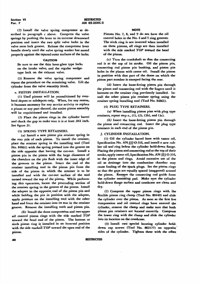
5/11/2018 Wright 2600 - slidepdf.com
http://slidepdf.com/reader/full/wright-2600 49/77
Section VI
Par. 7
RESTRICTEDAN 02-35HC-2
(2) Install the valve spring compressor as de-
scribed in paragraph c above. Compress the valve
springs by pushing the lever to its extreme downward
position and insert the two split valve locks in the
valve stem lock groove. Release the compressor lever
handle slowly until the valve spring washer ha s seated
properly against the tapered outer surfaces of the locks.
CAUTION
Be sure to me the thin hour-glass type locks
OIl the intake valve, and the regular wedge-
type lock OIl the .exhaust valve.
(3) Remove the valve spring' compressor and
repeat the procedure on the remaining valve. Lilt the
cylinder from the valve assembly block.
e. PISTON INsT ALLAnON.
(1) used pistons will be !CCOnditioned by over-
haul depots 01' subdepots only. When. for any reason.,
it becomes oecescary EoI' any service activity to replace
a piston. or any part thereof. the entire piston assembly
will be requisitioned and installed.
(2) Place the piston rings in the cylinder barrel
and check the gap to make sure it is at least .0« inch.
Sc:e6gure31.
(3) SPRING TYPE RETAINERS.
(III) Install a new piston pin retainer spring in
the rear ~ of each piston. To install the retainer,
place the retainer spring in the installing tool (Tool
No. 84861) with the spring pressed into the groove onthe side opposire that having the cut-out. Install a
pismo pin in the piston with' the large diameters of
the chamfers on the pin flush with the inner edge of
the grooves in the piston. Insert the end of the
reuiner installing tool in the piston pin from the
side of the piston in which the retainer is to be
installed and with the cut-out surface of the tool
twned ~ the top of the piston. While perform-
ing this operation, locate the protruding section of
the retainer spring in the groove of the piston. Install
the adaprer in the opposire. end of the piston pin and
while holding the pin in position with the adapter.
apply pressure on the installing tool with the other
hand and force the retainer. into its seat in the retainer
gruene. Remove the insralliog tools and piston pin.
(6) Install the three compression and twOupper
oil control piston rings with the side marked TOP
toward the head end of the piston. The bottom 01'
sixth piston ring is installed in an inverted position
with the side ~ TOP toward the open end of the
piston.
N O T E
Pistons No.7. 8, and 9 do DO haYC the oil
control holes in the No • .{and 5 ring grooves.
The sixth ring is not inYClUd when installaI
OIl these Pistons. all rings ace then installaI
with the side marked TOP rowacd the head
of the piston.
(c) Tucn the aankshaft so that the conncctiog
rod is at the top of its stroke. Oil the piston pin,
connecting rod piston pin bushing. and pismo pin
holes in the piston with astor oil. Install the piston
in position with that part of the dome OIl which the
piston part number is stamped facing the J'CaI'.
(J) Insert the 1oo5e-6ttiog piston pin through_
the piston and coDD«ting rod with the 6ngcn until it
bottoms on the retainer ring previously installed. In-
stall the other piston pin reuiner spring using the
retainer spring installing tool (Tool No. 84861).
(4) PLUG 1YPE RETAINERS..
(III) When installing piston pins with plug type
retainers, repeat step e., (I).(2). (3b). and (3c).
(b) Insert the Joose.-6tting piston pin through
the piston and connecting rod. Insert the plug type
retainers in each end of the piston pin.
t- CYUNDER INSTALLATION.
(I) Oil the cylindec barrel bore with astor oil,
Specification No. AN-JJJ-0-316, and install a new rub-
ber oil sea l ring below the cylinder hold-down flange.
Placing the piston and coonccting rod at the top of their
stroke, apply astor oil, Specification No. AN-JJJ-O--316,
to the piston and rings. Ayoid cxcessiYC me of the
oil as drainage into the combusrion chamber may
cause fouling of the spark plugs. Set the piston rings
50 that the gaps are equally spaa:d Cstaggeccd) around
the piston. ~ the coonccting rod guide from
the cylinder mounting pad. Make sure the cylinder
hoJd-down ftange surfacr and aank~ are clean anddry. •
(2) Compress the upper piston rings with the
ftexible piston ring clamp (Tool No. 80«0) and slide
the cyliOder OYer the pismo. As soon as the 6I '5l 6YC
coinpression and oil control rings ha..e entered t)Ie
cylindec. I'eJDOYChe clamp and make sure that bodl
piston pin retainers ace 10catal cocrectIy. Compress
the lower ring with the clamp and slide the cylinder
into its location OIl the aanlrotcr.
(3) Install twO Ispecial Joouing cylindec hold-
down cap screws (Tool No. 8021n) OIl opposite·
sides of the cylinder-. Tighlal these with the ofl'xt
40 RESTRlCIm
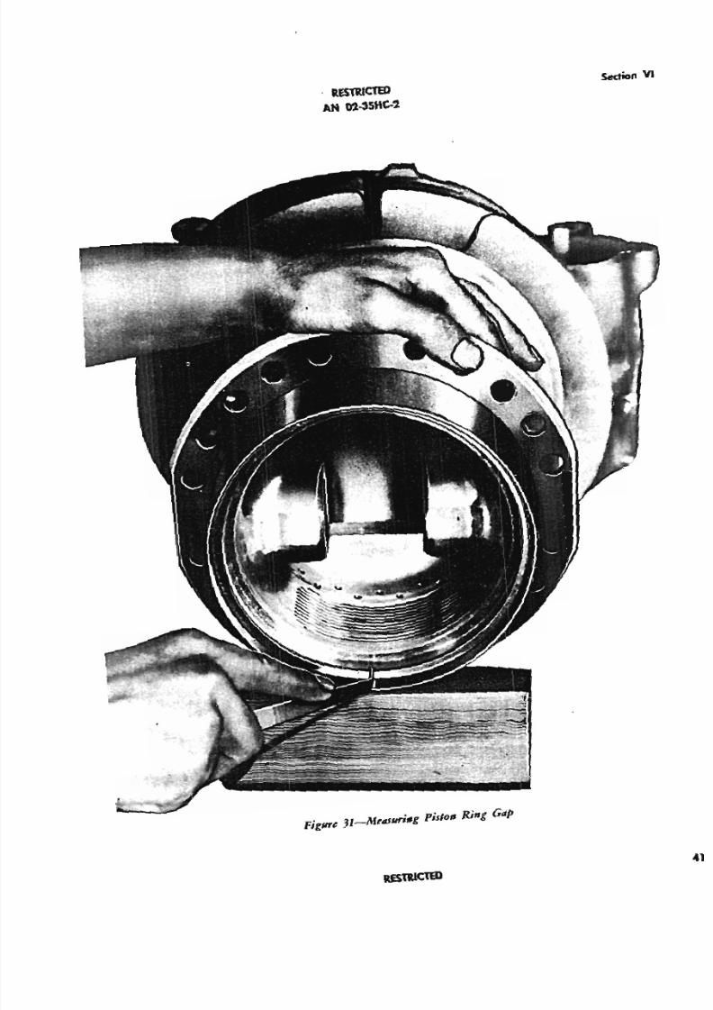
5/11/2018 Wright 2600 - slidepdf.com
http://slidepdf.com/reader/full/wright-2600 50/77
Sect ion V
. R E $ l1 lI C T E D
AN 02-35HC-2
Figure 31-i\{t'41uNflg piswn Ring Gap
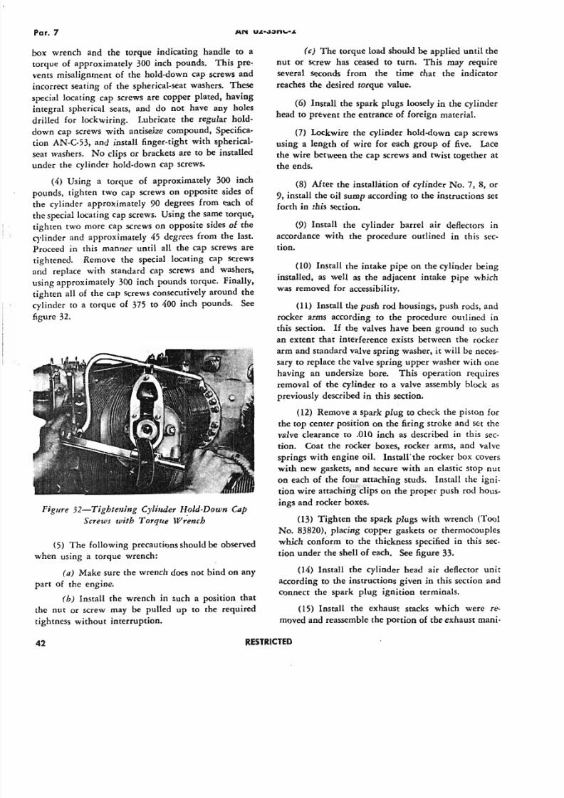
5/11/2018 Wright 2600 - slidepdf.com
http://slidepdf.com/reader/full/wright-2600 51/77
Par. 7
box wrench and the torque indicating handle to a
torque of approximately 300 inch pounds. This pre~
vents misalignment of the hold-down cap screws and
incorrect seating of the spherical-seat washers. These
special locating cap screws are copper plated, having
integral spherical seats, and do not have any holes
drilled for lockwiring. Lubricate the regular hold-
down cap screws with antiseize compound, Specifica-
tion AN-C-53, and install finger-tight with spherical-
seat washers. No clips or brackets are to be installed
under the cylinder hold-down cap screws.
(4) Using a torque of approximately 300 inch
pounds, tighten two cap screws on opposite sides of
the cylinder approximately 90 degrees from each of
the special locating cap screws. Using the same torque,
tighten two more cap screws on opposite sides of the
cylinder and approximately 45 degrees from the last.
Proceed in this manner until all the cap screws are
tightened. Remove the special locating cap screws
and replace with standard cap screws and washers,
using approximately 300 inch pounds torque. Finally,
tighten all of the cap screws consecutively around the
cylinder to a torque of 375 to 400 inch pounds. See
figure 32.
Figure 32-Tightening Cylinder Hold-Down Cap
Screws with 'Torque Wr~nch
(5) The following precautions should be observed
when using a torque wrench:
(a) Make sure the wrench does not bind on any
part of the engine.
(b) Install the wrench in such a posrnon that
the nut or screw may be pulled up to the required
tightness without interruption.
42
(c) The torque load should be applied until the
nut or screw has ceased to turn. This may require
several seconds from the time that the indicator
reaches the desired torque value.
(6) Install the spark plugs loosely in the cylinder
head to prevent the entrance of foreign material.
(7) Lockwire the cylinder hold-down cap screws
using a length of wire for each group of five. Lace
the wire between the cap screws and twist together at
the ends.
(8) After the installation of cylinder No.7, 8, or
9, install the oil sump according co the instructions set
forth in this section.
(9) Install the cylinder barrel air deflectors in
accordance with the procedure outlined in this sec-
tion.
(10) Install the intake pipe on the cylinder being
installed, as well as the adjacent intake pipe whichwas removed for accessibility.
(11) Install the push rod housings, push rods, and
rocker arms according to the procedure outlined in
this section. If the valves have been ground to such
an extent that interference exists between the rocker
arm and standard valve spring washer, it will be neces-
sary to replace the valve spring upper washer with one
having an undersize bore. This operation requires
removal of the cylinder to a valve assembly block as
previously described in this section.
(12) Remove a spark plug to check the piston for
the top center position on the firing stroke and set the
valve clearance to .010 inch as described in this sec-
tion. Coat the rocker boxes, rocker arms, and valve
springs with engine oil. Insrallthe rocker box covers
with new gaskets, and secure with an elastic Stop nut
on each of the four attaching studs. Install the igni-
tion wire attaching clips on the proper push rod hous-
ings and rocker boxes.
(13) Tighten the spark plugs with wrench (Tool
No. 83820), placing copper gaskets or thermocouples
which conf~rm to the thickness specified in this sec-
tion under the shell of each. See figure 33.
(14) Install the cylinder head air deflector unit
according to the instructions given in this section and
connect the spark plug ignition terminals.
(15) Install the exhaust stacks which were re-
moved and reassemble the portion of the exhaust mani-
R E S T R I C T E D
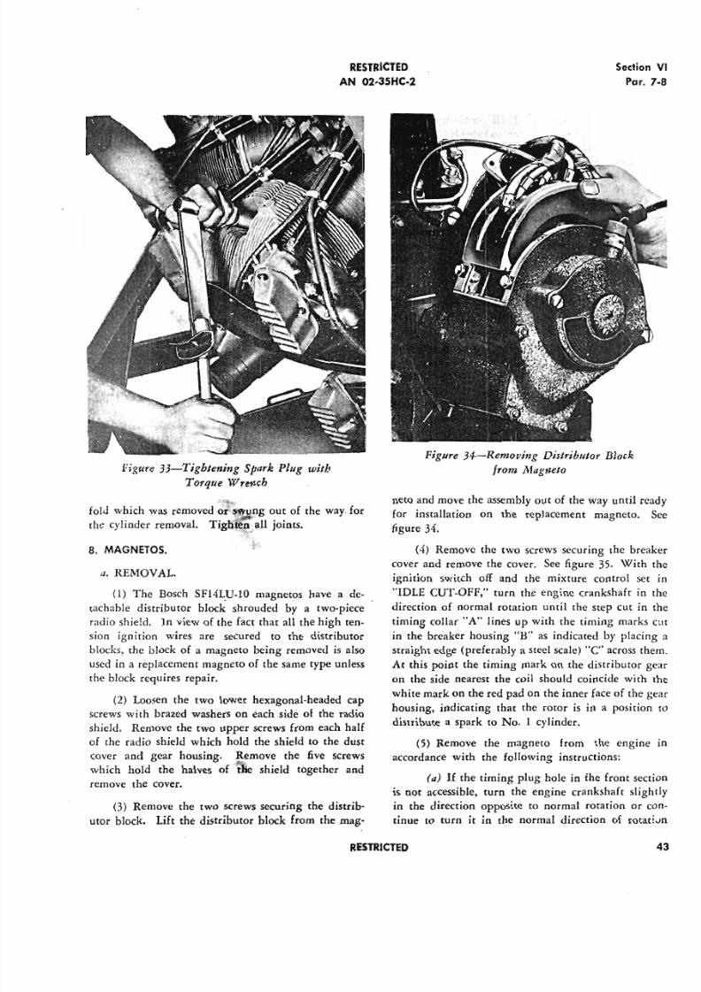
5/11/2018 Wright 2600 - slidepdf.com
http://slidepdf.com/reader/full/wright-2600 52/77
RESTRICTED
AN 02-3SHC-2
Figure 33-Tightening Spark Plug with
Torque Wrench
.~'"fold which was removed or'~n.g out of the way for
the cylinder removal. Tighten"all joints.
8. MAGNETOS.
a. REMOVAL.
0) The Bosch SF14L.U-IO magnetos have a de-
tachable distributor block shrouded by a two-piece
radio shield. In view of the fact that all the high ten-
sion ignition wires are secured to the distributor
blocks, the block of a magneto being removed is also
used in a replacement magneto of the same type unless
the block requires repair.
(2) Loosen the two lower hexagonal-headed cap
screws with brazed washers on each side of the radio
shield. Remove the two upper screws from each half
of the radio shield which hold the shield to the dust
cover and gear housing. Remove the five screws
which hold the halves of ftie shield together and
remove the cover.
(3) Remove the two screws securing the distrib-
utor block. Lift the distributor block from the mag-
Sectio
Pa
Figure 34-Removing Distributor Block
from Magneto
nero and move the assembly out of the way until
for installation on the replacement magneto.figure 34.
(4) Remove the two screws securing the bre
cover and remove the cover. See figure 35. With
ignition switch off and the mixture control s
"IDLE CUT-OFF," turn the engine crankshaft i
direction of normal rotation until the step cut i
timing collar "A" lines up with the timing mark
in the breaker housing "H" as indicated by plac
straight edge (preferably a steel scale) "C" across
At this point the timing mark on the distributor
on the side nearest the coil should coincide with
white mark on the red pad on the inner face of the
housing, indicating that the rotor is in a positio
distribute a spark to No. 1 cylinder.
(5) Remove the magneto from the engin
accordance with the following instructions:
(a) If the timing plug hole in the front se
is not accessible, turn the engine crankshaft sli
in the direction opposite to normal rotation or
tinue to turn it in the normal direction of rot
RESTRICTED
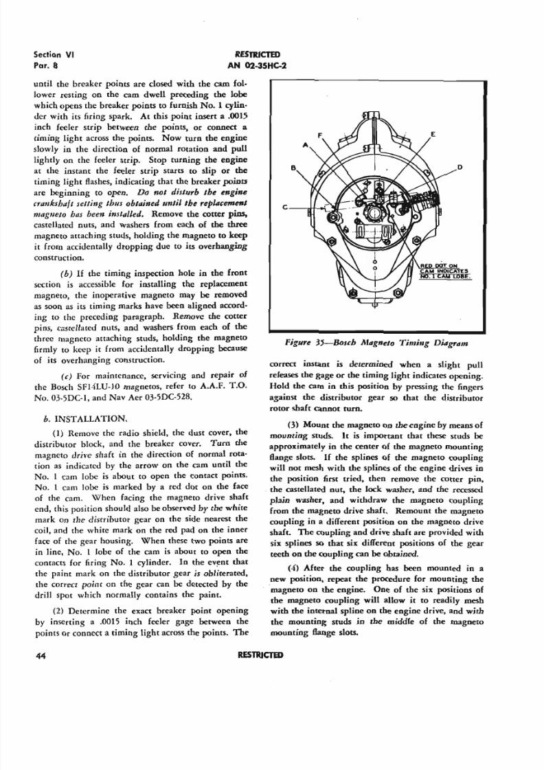
5/11/2018 Wright 2600 - slidepdf.com
http://slidepdf.com/reader/full/wright-2600 53/77
Section VI
Par. 8
R E S T R I C T E D
AN 02-35HC-2
until the breaker points are dosed with the cam fol-
lower resting on the cam dwell preceding the lobe
which opens the breaker points to furnish No. I cylin-
der with its firing spark. At this point insert a .0015
inch feeler strip between the points, or connect a
timing light across the points. Now turn the engine
slowly in the direction of normal rotation and pull
lightly on the feeler strip. Stop turning the engine
at the instant the feeler strip starts to slip or the
timing light flashes, indicating that the breaker points
are beginning to open. Do not disturb the engine
crankshaft selling thus obtained until sbe replacement
magllelo has been instaIJed. Remove the cotter pins,
castellated nuts, and washers from each of the three
magneto attaching studs, holding the magneto to keep
it from accidentally dropping due to its overhanging
construction.
(b) If the timing inspection hole in the front
section is accessible for installing the replacement
magneto, the inoperative magneto may be removed
as soon as its timing marks have been aligned accord-
ing to the preceding paragraph. Remove the cotter
pins, casrcllated nuts, and washers from each of the
three magneto attaching studs, holding the magneto
firmly to keep it from accidentally dropping because
of its overhanging construction.
(c) For maintenance, servicing and repair of
the Bosch SF14LU-1O magnetos, refer to A.A.F. T.O.
No. 03-5DC-l, and Nav Aer 03-5DC-528.
b. INSTALLATION.
(1) Remove the radio shield, the dust cover, the
distributor block, and the breaker cover. Turn the
magneto drive shaft in the direction of normal rota-
tion as indicated by the arrow on the cam until the
No. 1 cam lobe is about to open the contact points.
No. 1 cam lobe is marked by a red dot on the face
of the cam. \Vhen facing the magneto drive shaft
end, this position should also be observed by the white
mark on the distributor gear on the side nearest the
coil, and the white mark on the red pad on the inner
face of the gear housing. When these two points ace
in line, No. 1 lobe of the cam is about to open the
contacts for firing No. 1 cylinder. In the event that
the paint mark on the distributor gear is obliterated,
the correct point on the gear can be detected by the
drill spot which normally contains the paint.
(2) Determine the exact breaker point opening
by inserting a .0015 inch feeler gage between the
points or connect a timing light across the points. The
44
Figure 35-Bosch l'tfagneto Timi"g Diagralll
COrrect instant is determined when a slight pull
releases the gage or the timing light indicates opening.
Hold the cam in this position by pressing the fingers
against the distributor gear so that the distributor
rotor shaft cannot turn.
(3) Mount the magneto on the engine by means of
mounting studs. It is important that these studs be
approximately in the center of the magneto mounting
flange slots. If the splines of the magneto coupling
will not mesh with the splines of the engine drives in
the position first tried, then remove the cotter pin,
the castellated nut, the lock washer, and the recessed
plain washer, and withdraw the magneto coupling
from the magneto drive shaft. Remount the magneto
coupling in a different position on the magneto drive
shaft. The coupling and drive shaft are provided with
six splines so that six different positions of the gear
teeth on the coupling can be obtained.
(4) Mter the coupling bas been mounted in a
new position, repeat the procedure for mounting the
·magneto on the engine, One of the six positions of
the magneto coupling will allow it to readily mesh
with the internal spline on the engine drive, and with
the mounting studs in the middle of the magneto
mounting flange slots.
R E S T R I C T E D
5/11/2018 Wright 2600 - slidepdf.com
http://slidepdf.com/reader/full/wright-2600 54/77
RESTRlClID
AN 02-35HC-2
(5) Mtcc determining this position, remove the
magneto from the engine and secure the coupling
with the recessed plain washer. lock washer, castel-
lated nut, and rotter pin. Apply a heavy grade of
petrolatum, Speci6cation AN-VV-P-236, to the splines
of the magoeoo drive shaft roupliog and reinstall themagneto in the correct predetermined position..
(6) When both magnetos have been mounted.
tighten the holding nuts firmly. but loose enough so
that the magnetos may be moved in the mounting
Bange slots for final accurate adjustments (synchr0-
nizing) to the engine-
c. FINAL TIMING OF MAGNETO TO ENGINE.
(1) When making final timing adjustments of the
magnetos 00 the engine. all adjustments must be made
through the drive roupling assemblies by turning thecomplete magnetos in their flange mounting slots. For
synchronized sparks of both mageetos, -both sets of
points of No. Icam lobe must open simultaneOusly.
(2) Although final timing of both magnetos to
the engine can be carried on at the same time. it is
r ecommended that one magneto only be timed per-
fectly 00 the engine. and the serond magneto be syn-
chronized with the first one, This final timing and
synchronization is done in the following manner:
With the piston of No. 1cylinder in the advanced fir-
ing position required on the rompression stroke and
both magnetoS having been mounted as outlined. pro-
ceed as follows:
(II) Assuming that the left magneto is the one
chosen for timing 00 the engine. loosen its holding
nuts on the retaining studs sufficiently to permit rotat-
ing the entire magneto slighdy in its mounting B . a . n g e
slots. Rotate the magoeoo flange until the cam fol-
lower UF' is in the cam dwell preceding No. 1cam
lobe with the breaker points "En dosed. Connect a
timing light, one lead should be grounded and the
other two leads connected to the breaker points.
NOTE
The timing light is preferred because it pro-
vides a more accurate check of the opening
of the rontact points and provides less prob-
ability of damage 00 the breaker points than
any other method. Inan emergency a feeler
gage or a piece of shim stock not to exceed
.0015 inch may be used.. The gage or shim
stock must be degreased. cleaned, and dried
Sectio
P
thoroughly before it is inserted between the
rontaet points 00 check for their opening.
Now rotate the magneto flange carefully until the
ing light indicates the points are opening. or unti
feeler strip is released by a gende pull To iabsolute accuracy. the contact opening position s
be rechecked before tightening with fastening
sufficiendy 00 permit any movemcm of the mag
bot loose enough for further adjustment,
(6) Engine timing should be checked with
engine timing marks by movement of the cranks
Rotate the crankshaft in the direction opposite 00
mal rotation at approximately one-quarter turn.
reverse the rotation sufficiendy 00 bring the cam
lower inoo the cam dwell preceding No. Icam
At this position connect the timing light acros
points, or insert a .0015 inch feeler gage. Continu
move the craokshaEt in the direction of normal
tion by a very slight jarring movement until th
gine timing pointer is at the engine timing m
The timing light or the release of the feeler
should indicate the points are opening under contin
jarring action on the crankshaft while the engine
ing pointer is within the engine' timing mark.
setting should also be rechecked..
(c) The correct setting having been obta
secure the left-hand magneto by means of the ho
nuts. Do not disturb the setting.
(d) With the engine and the left-hand
neto in the above position, adjust the right-hand
neto in its mounting slots until the breaker points
open. using the timing light method or a feeler
This is the synchronizing operation and shoul
carefully carried out. The right-hand magneto s
now be tightened. but only enough 00 permit fu
adjustment if necessary-
(e) Finish thesynchrooization of both mag
with the eogioe by turning the crankshaf1: inthe d
tion opposite to normal rotation approximately
quarter turn, and then turning in the direction of
mal rotation until the cam followers are in the
dwell preceding the No. 1cam lobe. Connect the
ing light across both sets of points or insert
strips.
(/J Continue to turn the the crankshaft i
normal direction of rotation by a slight jarring a
on the crankshaft turning tool. Both light bulb
the timing light must indicate the points are ope
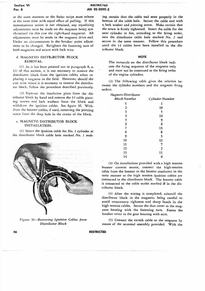
5/11/2018 Wright 2600 - slidepdf.com
http://slidepdf.com/reader/full/wright-2600 55/77
Section VI
Par. 8
RESTRICTl :D
AN 02-35HC-2
at the same moment or the feeler strips must release
at the same time with equal effort of pulling. If this
instantaneous action is not obtained, any equalizing
adjustments must be made on the magneto being syn-
chronized (in this case the right-hand magneto). All
adjustments must be made in the magneto drive end.
Under no circumstances is the breaker point adjust-
ment to be changed. Retighten the fastening nuts of
both magnetos and secure with lock wire.
d. MAGNETO DISTRiBUTOR BLOCK
REMOVAL.
(1) As it has been pointed out in paragraph 8, a,
(1) of this section, it is not necessary to remove the
distributor block from the ignition cables when re-
placing a magneto in the field. However, should the
case arise where it is necessary to remove the distribu-
tor block, follow the procedure described previously.
(2) Separate the insulation plate from the dis-
tributor block by hand and remove the 11 cable pierc-
ing screws and lock washers from the block andwithdraw the ignition cables. See figure 36. With-
draw the booster cables, if used, removing the piercing
screw from the deep hole in the center of the block,
e. MAGNETO DISTRIBUTOR BLOCK
INSTALLATION.
(1) Insert the ignition cable for No.1 cylinder at
the distributor block cable hole marked No. 1 rnak-
Figure 36-Remof·ing Ignition Cables from
Distributor Block
ing certain that the cable end seats properly in the
bottom of the cable hole. Secure the cable end with
a lock washer and piercing screw. Make certain that
the screw is firmly tightened. Insert the cable for the
next cylinder to fire, according to the firing order,
into the distributor cable hole marked No. 2 and
secure in the same manner. Follow this procedure
until the 14 cables have been installed in the dis-
tributor block.
NOTE
The numerals on the distributor block indi-
cate the firing sequence of the magneto only
and must not be construed as the firing order
of the engine cylinders.
(2) The following table gives the relation be -
tween the cylinder numbers and the magneto firing
orders:
Afagnelo Distributor
Block Number Cylinder Number
1 1
2 10
3 5
4 14
5 9
6 4
7 138 8
9 310 12
11 7
12 2
13 1114 6
(3) On installations provided with a high tension
booster current source, connect the high-tension
cable from the booster to the booster conductor in the
same manner as the high tension ignition cables are
connected to the distributor block. The booster cable
is connected to the cable outlet marked B in the dis-
tributor block.
(4) After the wiring is completed, reinstall the
distributor block in the magneto, being careful to
avoid unnecessary tightness and sharp bends in thehigh tension cables. Secure the dust cover to the mag-
neto housing with the fastening nuts. Fasten the
breaker cover to the gear housing with nuts.
(5) Connect the switch cable to the magneto by
means of the terminal assembly provided. With the
46 RESTRICTED
5/11/2018 Wright 2600 - slidepdf.com
http://slidepdf.com/reader/full/wright-2600 56/77
RESTRICTED
AN 02-35HC-2
terminal inserted and held firmly in place by the
slotted nut, the clearance between the automatic
grounding spring in the breaker assembly rear hous-
ing rim must be at least 3/32 inch.
NOTEAll American Bosch aviation magnetos are
furnished with a short-circuiting spring
which will automatically contact the inner
rim of the gear housing when the terminal
(switch) assembly is removed from the latter,
thereby short-circuiting the primary circuit.
This prevents the possibility of a high-tension
secondary voltage being built up which might
otherwise result in unexpected ignition.
Whenever the switch cable is connected to
the magneto, however, the magneto switch
must be kept in the "OFF" position to pre-vent accidental starting of the engine.
9. RADIO SHIELDED IGNITION CABLE ASSEMBLY.
a. REMOVAL.
(1) Disconnect the shielded ignition cable termi-
nals from the spark plugs of all cylinders.
(2) Remove all spark plug conduit attaching clips
from the push rod housings of the front row cylin-
ders, leaving the clips on the conduits with their
clamp screws and nuts temporarily reinstalled.
(3) Remove the clip attaching screws and nutssecuring the rear spark plug conduits of all the cyl-
inders to the brackets on the intake rocker boxes of
the front row cylinders. Leave the clips and tempo-
rarily reinstalled screws and nuts on the conduits.
Do not remove the brackets which hold the spark plug
conduits away from the cylinder head 6ns.
(4) Loosen the main radio shielded conduits from
their crankcase h·.lckets by removing the lock wire,
screws, and washers securing the upper halves of the
brackets to the lower halves.
(5) Remove the radio shielded distributor block
from each magneto, disassemble, and withdraw allignition wires according to instructions in paragraph
8, d, (2) of this section. Unscrew the knurled cou-
plings and slide the adapter from the rear end of each
of the main ignition conduits.
(6) Withdraw the rear spark plug conduits from
the spark plug cooling air ducts in the cylinder head
air deflectors, being careful not to damage the termi-
nal contacts.
Sedi
Pa
(7) Remove the cylinder barrel air deflectors
cylinders No.3, 4, 12, and 13 following the in
tions outlined in paragraph 3 of this section.
(8) Remove the four elastic stop nuts sec
the ignition manifold ring to the nose sectionengine. Loosen the knurled coupling holding
jointed manifold ring together, the couplings a
ing the large flexible conduits to the manifold,
remove all controls and lines which hamper
moval. Withdraw the shielded ignition cable
bly forward from the engine in the most conve
manner permitted by the installation.
b. INSTALLA TION.
(1) Prepare the replacement radio shielded
tion cable assembly for installation by removin
distributor blocks according to instructions in
graph 8, d of this section. Unscrew the knurled
plings and remove the adapter from the rear e
each large flexible conduit, being careful not to
the gasket on the adapter. Loosen the knurled
plings securing the two large flexible conduits t
manifold ring, as well as the knurled coupling a
ing the two halves of the jointed manifold
together.
(2) Place the assembly in position on the en
passing the large flexible conduit for the left
neto between No. 12 and No. 13 cylinders an
conduit for the right magneto between No.3 and
4 . cylinders. Place the four drilled lugs projec
from the inside diameter of the manifold ring
the proper front section studs, and reinstall the
tic stop nuts, if still in good condition, which
removed with the replaced shielding assembly. Tig
the knurled couplings securing the halves of the
fold ring together and those securing the main
duits to the manifold ring, having the gasket
erly seated between each joint.
(3) Install the magneto outlet adapter with
ket on the rear end of each large flexible con
Powdered mica or talc on the ignition cables wil
in their installation. Leave the knurled coup
loose enough to permit adjusting the position o
adapters. Connect the magneto distributor b
and radio shielding to the ignition cables and i
in each magneto following the instructions in
graph 8, e, of this section.
(4) Place the large flexible conduits in the
half of their crankcase brackets which are bolte
the crankcase between cylinders No. 12 and 13
RESTRICTED
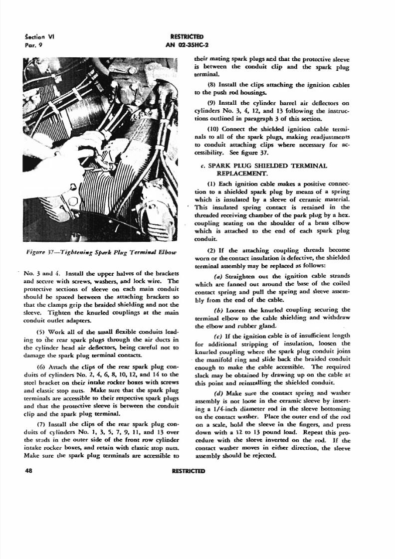
5/11/2018 Wright 2600 - slidepdf.com
http://slidepdf.com/reader/full/wright-2600 57/77
Section V1
Par. 9
RESTRICTED
AN 02-35HC-2
Pigure 37-Tighleni.g Spllrk Plug Term;..! Elbow
No.3 and - 4 . Install the upper halves of the brackets
and secure with screws. washers. and lock wire. The
protective sections of sleeve on each main conduit
should be spaced between the attaching brackets so
that the clamps grip me braided shielding and not the
sleeve. Tighten the knurled couplings at the maio
conduit outlet adapters,
(5) Work all of the small flexible conduits lead-
ing to the rear spark plugs through the air ducts in
me cylinder head air deflectors. being careful not to
damage me spark plug terminal contacts.
(6) Attach me clips of the rear spark plug con-
duits of cylinders No. 2. 4, 6. 8, 10, 12. and 14 to the
steel bracket on their intake rocker boxes with screws
and elastic stop nuts, Make sure that the spark plug
terminals arc accessible to their respective spark plugs
and that the protective sleeve is between the conduit
clip and me spark plug terminal.
(7) Install the dips of the rear spark plug con-
duits of cylinders No. It 3, 5~ 7, 9, n, and 13 over
me studs in me outer side of the front row cylinder
intake rocker boxes. and retain with elastic stop nuts,
Make sure the spark plug terminals arc accessible to
48
their mating spark plugs aed lhat the protective sleeve
is between the conduit clip and the spark plug
terminal.
(8) Install the clips attaching the ignition cab les
to the push rod housings.
(9) Install the cylinder barrel air deflectors on
cylinders No.3. 4. 12. and 13 following the instruc-
tions outlined in paragraph 3 of this section.
(10) Connect the shielded ignition cable termi-
nals to all of the spark plugs. making readjustments
to conduit attaching clips where necessary for ac-
cessibility. See figure 37.
c. SPARK. PLUG SHIELDED TERMINAL
REPLACEMENT.
(I) Each ignition cable makes a positive connec-
tionto
a shielded spark plug by means of a springwhich is insulated by a sleeve of ceramic material.
This insulated spring contact is retained in the
threaded receiving chamber of the park plug by a hex.
coupling seating on the shoulder of a brass elbow
which is attached to the cod of each spark plug
conduit,
(2) If the artaching coupling threads become
worn or the contact insulation is defective. the shielded
terminal assembly may be replaced as follows:
(II) Straighten Out the ignition cable strands
which arc fanned out around the base of the coiled
contact spring and pull the spring and sleeve assem-bly from the end of the cable.
(b) Loosen the knurled coupling securing the
terminal elbow to the cable shielding and withdraw
the elbow and rubber gland.
(c) If the ignition cable is of insufficient length
for additional stripping of insulation, loosen the
knurled coupling where the spark plug conduit joins
- the manifold ring and slide back the braided conduit
enough to make the cable accessible. The required
slack may be obtained by drawing up on the cable at
this point and reinstalling the shielded conduit.
(d) Make sure the contact spring and washer
assembly is not loose in the ceramic sleeve by insert-
ing a IN-inch diameter rod in the sleeve bottoming
on the contact washer. Place the outer end of the rod
on a sca le . hold the sleeve in the fingers. and press
down with a 12 to I3 pound load. Repeat this pro-
cedure with the sleeve inverted on the rod. If the
contact washer moves in either direction. the sleeve
assembly should be rejected.
RESTRICTED
5/11/2018 Wright 2600 - slidepdf.com
http://slidepdf.com/reader/full/wright-2600 58/77
RESTRICTED
AN 02-35HC-2
(e) Install the replacement shielded terminal
elbow on the end of the spark plug COQduit, having
a new rubber gland in the joint between the two.
Twist the strands of the ignition cable s1ighdy to
enter the tecminal contact readily and insert the cable
into the ceramic sleeve with its stripped end extending
through the hole at the base of the contact spring.
No solder is necessary. Press the wire strands securely
into position over the end of the contact washer nipple
by means of a small copper tube; liS-inch inside
diameter.
d. SPARK. PLUG SHIELDED CONDUIT
REPLACEMENT.
(1) Replacing any individual ignition cable in a
radio shielded cable assembly is not recommended.
but any defective shielded spark plug conduit may be
replaced easily as foUows:
(a) Remove the spack plug tecminaI elbow
and contact according to instructions in paragraph
9. II.
(b) Loosen the knurled coupling attaching the
spark plug shielded conduit to the manifold ring and
slide the conduit and rubber grommet off the ignition
cable.
(c) Slip a new rubber grommet over the igni-
tion wire with its tapered end seating in the manifold
ring. Slide the replacement ftexible shielded conduit
over the spark plug ignition cable. Make sure amplecable is provided to attach the spack plug shielded
terminal, and tighten the knurled coupliog on the
manifold ring.
(d) Install the spack plug shielded terminal
elbow and contact on the end of the ignition cable
according to the instructions in paragraph 9, b.
10. CARBURETORS.
II. GENERAL-For maintenance and servicing of
the Bendix Stromberg injection carburetors with
which these engines ace equipped. refer to A.A.F.
T.O. No. 03-10BA-2.
b. REMOVAL
(1) Disconnect the throttle and mixture controls.
Remove the lines from the following connections in
the most convenient manner allowed by the engine
installation.
(a) Fuel inlet, at the bottom of the regulator
unit.
Sectio
Par.
(b) Fuel pressure. at the left of the fuel
connection.
(c) Vapor separator, on top of the fuel stra
chamber.
(d) Fuel pump sylphon vent, in the carbur
air scoop or throttle body top flange.
(e) Remove tbe air intake temperature bulb
intake air heater controls from the air scoop.
move the temperature bulb from the discharge
sembly. Remove the elastic stop nulS from the
air scoop retaining studs on the top flange of
carburetor throttle body and lift off the air s
(or the section of which is attached to the carburet
(j) Remove the twelve lock nulS and spher
seat washers secucing the carburetor and discharge
sembly to the supercharger rear housing. Removecarburetor and discharge assembly and cover
mounting flange with a metal or wood plate.
c. INSTALLATION.
(1) Before installing the carburetor, prepar
for service by flushing it with gasoline foUowing
practice employed in preparing it for storage as
lined in section m, except employing gasoline t
move all traces of the slushing oiL
(2) Remove the cover plate from the mout
the induction passage in the superchacger rear h
ing and place a new gasket over the attaching sInstall the carburetor and dischacge assembly on
mounting flange and secure with spherical-seat w
ers and lock nots.
(3) Install the temperature bulb in the disch
assembly. lnstall lines on the fuel inlet, fuel
sure, and vapor separator connections in the o
that space renders most convenient. Connect
throttle and mixture controls and check for fuU t
at the carburetor.
(4) Place a gasket over the cacbucetor air s
attaching studs above the air intake screen rim
install the air scoop (or the section of which i
tached to the carburetor). lnstall nuts over the
retaining studs and lock with elastic stop nuts.
nect the air intake heater control and check for
plete travel of the shutter. lnstall the carburetor
intake temperature bulb in the air scoop. Con
the fuel pump sylphon vent to the l/S-inch
tapped hole in the right top flange of the thr
body, not the tapped hole in the throttle body b
RESTRICTED
5/11/2018 Wright 2600 - slidepdf.com
http://slidepdf.com/reader/full/wright-2600 59/77
...v .... v ••••
Par. 1()..15 A N 02 -35H C·2
13. G EN ER ATO R R EPLA C EM EN T.he upper flange. If there is no provision for a con-
nection in the upper Range, connect the fuel pump
diaphragm vent directly to the air scoop. This is to
prevent fuel from accidentally entering the air cham-
bers of the carburetor in the event of a fuel pump
diaphragm failure.
11. PR IM IN G SY STEM .
a. REMOVAL OF TUBING AND
DISTRIBUTOR.
(1) The engine is equipped with a two-point
priming system with an optional third point con-
trolled by a shut-off valve in the distributor block.
Unscrew and remove the priming tubes and union
nuts from the fittings on both sides of the discharge
assembly and from the fitting on the supercharger
front housing.
(2) Unscrew and detach the four fittings, tubing,
and shut-off valve from the distributor block located
on the right side of the discharge assembly. Unscrew
and detach from the carburetor the fitting which at-
taches the priming tube to the distributor block.
h. INSTALLATION OF TUBING AND
DISTRIBUTOR.
(I) Attach and lock the distributor and support
on the right side of the discharge assembly. Install
the elbow in the carburetor fuel inlet. Install the rwo
fuel primer discharge nipples in the discharge assem-
bly, one in the left and one in the right side.
(2) Attach a tube from the fuCCIprimer discharge
nipple in the left side of the discharge assembly to an
elbow in the distributor block. Attach another tube
to the fuel primer discharge nipple in the right side of
the carburetor adapter and to an elbow in the distribu-
tor block. Install another tube from the distributor
block to the elbow in the fuel inlet of the carburetor.
(3) Install the third point of priming at the sup-
ercharger front housing and the shut-off valve in the
distributor block.
12 . ST AR TE R R EPL AC EM EN T.
fl. The starter is secured to its mounting pad in the
center of the supercharger rear housing cover by six
equally spaced studs on which are screwed elastic stop
nuts.
h. When replacing the starter, refer to the applica-
ble technical order for the type of starter being re-
moved Or installed.
II. The generator is secured to its mounting pad just
below the Starter on the supercharger rear housing
cover by six equally spaced studs on which are screwed
elastic stop nuts.
b. When replacing the generator, refer to the ap-
plicable technical order for the particular type gen-
erator used to obtain wiring instructions and completeservicing information. .
14 . FU EL PU M P R EPLA CEM EN T .
II. The fuel pump is mounted on the outer end of
the tachometer drive shaft housing. The fuel pump
and tachometer housings are secured to the lower
mounting pad on the right side of the supercharger
rear housing by four studs, washers, castellated nuts,
and lock wire.
b. When replacing the fuel pump, refer to the tech-
nical order covering the type of fuel pump being
removed or installed and to paragraph 15 immediatelybelow.
15. FU EL PU M P-TA CH O METER D R IV E A SSEM BLY .
a, REMOVAL AND DISASSEMBLY.
(1) The two tachometer drive shaft assemblies
may be removed from the magnesium alloy block on
which they are mounted, and replacements made
without removing the fuel pump. The spiral teeth
on the inner ends of these two shafts mesh with spiral
teeth on the fuel pump-tachometer drive shaft. To
avoid the possibility of dropping the fuel pump-
tachometer drive shaft into the supercharger rearhousing, the magnesium alloy fuel pump-tachometer
supporting block should not be withdrawn from its
attaching studs unless the two tachometer shaft as-
semblies are securely in place to limit the end move-
ment of the fuel pump-tachometer drive shaft. In-
structions for the replacement of individual tachometer
shaft assemblies are included in the following removal
and disassembly instructions for the entire fuel pump-
tachometer drive unit.
(2) Remove the fuel pump inlet, outlet, drain and
vent lines from their respective connections. Break
the lock wire, remove the nuts and washers from the
four fuel pump attaching studs, and withdraw the
fuel pump and gasket.
(3) Detach the tachometer connection from the
outer end of whichever of the two tachometer shafts
is being used.
50 RESTR ICTED
5/11/2018 Wright 2600 - slidepdf.com
http://slidepdf.com/reader/full/wright-2600 60/77
RESTRICTED
AN 02-35HC-2
(q) Wirhdraw the fuel pump-tachometer mount-
Iny block complete with both tachometer drive shaft
assemblies and the fuel pump-tachometer drive shaft
with its support which is attached to the inner end
of the magnesium alloy mounting block. Plug the
opening in the supercharger rear housing to prevent
the entrance of foreign material. and remove the com-
plete drive unit to a bench for disassembly.
(5) Break the lock wire and remove the two cap
screws securing each tachometer drive shaft oil seal
housing to the magnesium alloy mounting block.
Remove the two housings complete with packing.
followed by the packing springs. Remove the loose-
fitting tachometer drive shaft bushings and gaskets
from the mounting block. after which the two ta-
chometer drive shafts may be lifted out.
(6) Withdraw the fuel pump-tachometer drivefrom the inner end of its support. Remove the flat-
head screw securing the fuel pump-tachometer drive
shaft support to the magnesium alloy mounting block
and separate the two parts.
b. FUEL PUMP DRIVE SHAFT OIL SEAL RE-
PLACEMENT.- The fuel pump drive shaft oil seal
assembly consists of a steel cup in which is assembled
a leather seal reinforced by a coiled spring. This as-
sembly is replaced as one unit and cannot be disas-
sembled. Removal is effected by driving or pressing
the tight-fitting steel cup out of the magnesium alloy
mounting block from the inner end. The replace-ment oil seal assembly is pressed in from the outer
end until the spring side bottoms in the mounting
block.
c. ASSEMBLY AND INSTALLATION.
(1) Attach the fuel pump-tachometer drive shaft
support to the inner end of the magnesium alloy fuel
pump and tachometer mounting block with the single
flat-head screw, having a gasket between the two parts.
It is not ilecessary to stake this screw.
(2) Lubricate the leather fuel pump drive shaft
oil seal with engine oil and insert the fuel pump-
tachometer drive shaft until the shoulder on its
toothed end bottoms on the inner supporting bushing.
(3) MECHANICAL TACHOMETER DRIVE.
(a) Place a gasket on both sides of the bronze
drive shaft bushing attaching flange. Oil the drive
shaft with engine oil and install in the bore of each
bushing. Insert the bushings and accompanying
Section
Par
shafts into the mounting block. turning the sh
slightly to mesh the spiral gear teeth with those
the fuel pump-tachometer drive shaft.
(b) Insert a new spherical-seat packing ring
synthetic rubber material followed by an alumin'washer in the drive shaft oil seal bushing. Plac
coiled packing spring over the extended end of
drive shaft, followed by the housing complete w
packing and washer. Secure the oil seal housing
the mounting block with two cap screws, install
lock washers under the head of each. Lockwire
cap screws.
(4) ELECTRIC. TACHOMETER DRIVE.
(a) If the plug, bushing, and collar have b
removed from the drive shaft, install the long bush
over the driving end of the shaft and tap the co
in place over it. Make sure the collar bottoms on
shoulder of the shaft. Tap the plug into the dri
end of the shaft until the shoulder of the plug
toms on the bottom of the shaft.
(b) Install the drive shaft assembly in its
in the mounting block, turning the shaft as thi
done to mesh the spiral gears easily.
(c) Install washer, ring, and retainer res
tively over the driving end of the shaft and se
with three cap screws. When tightening the
screws, insert a small piece of feeler gage stock
tween the shaft and retainer, moving it aroundshaft as the screws are tightened to insure that
shaft does not get jammed out of center by the
tainer. Lockwire the cap screws.
(d) If an electric tachometer is to be used,
stall it with a new gasket, otherwise install a
gasket and cover plate, securing them in place w
four elastic stop nuts.
(5) The fuel pump-tachometer drive unit is n
ready for installation on the engine. Rotate the m
drive shaft and check the operation of the tachome
drive shafts. Place a gasket on the drive shaft supp
flange and install the unit over the four attaching s
in the supercharger rear housing. Turn the d
shaft by its splined fuel pump driving end to m
the bevel gear teeth at its inner end properly w
those cut in the spare accessory drive shaft.
(6) Attach the tachometer connections. Whe
cap is used over a mechanical tachometer drive,
stall a fiber washer in its base to avoid its bottom
on the oil seal housing.
RESTRICTED
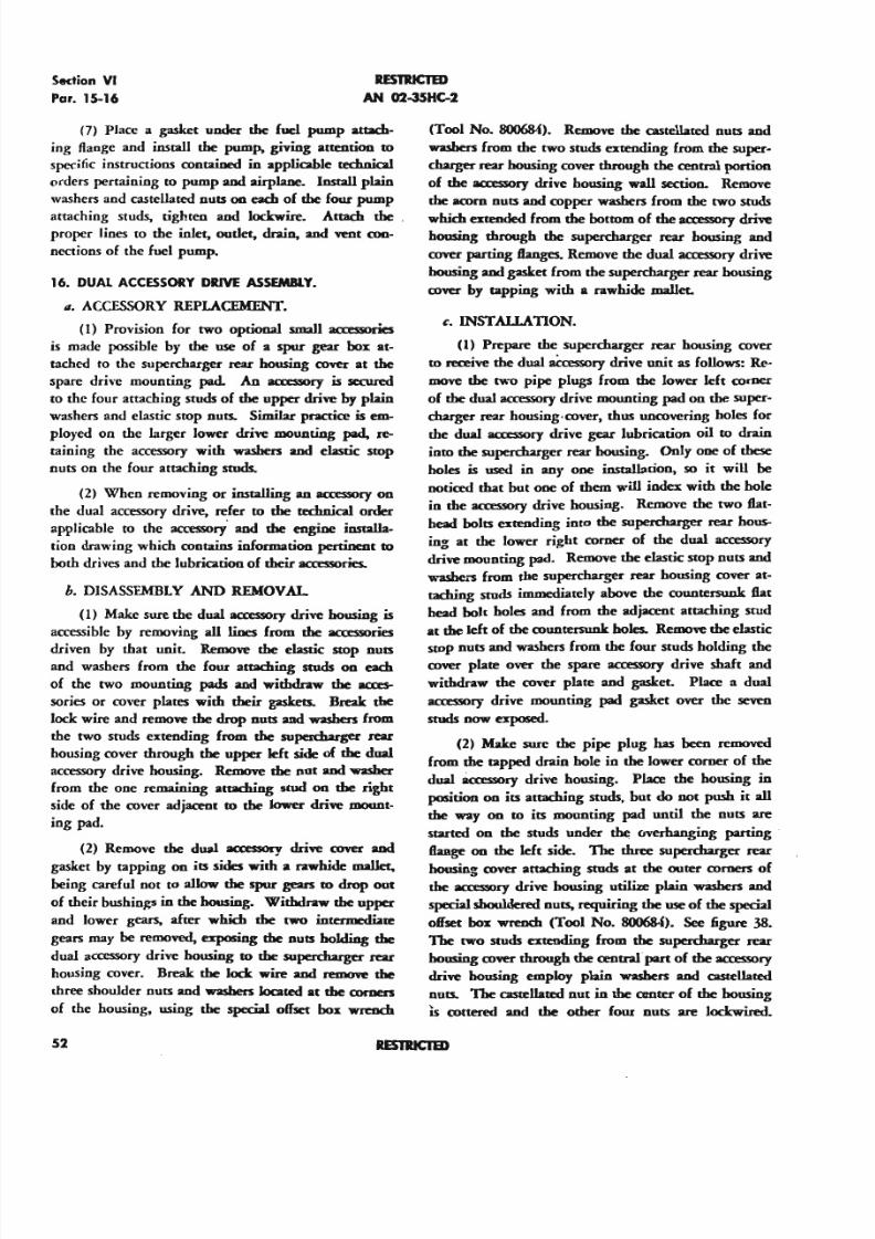
5/11/2018 Wright 2600 - slidepdf.com
http://slidepdf.com/reader/full/wright-2600 61/77
Section V I
Par. 15-16
RESTRICTED
AN 02-35HC-2
(7) Place a gasket under the fuel pump attach-
ing flange and install the pum~ giving attention to
specific instructions contained in applicable rechnical
orders pertaining to pump and airplane. Install plain
washers and castellated nulS OIl each of the four pump
attaching studs, tighten and lockwire. Attach theproper lines to the inlet, onder. drain. and ~t con-
nections of the fuel pump.
16. DUAl ACCESSORY DRIVE ASSEMBlY.
IZ. ACCESSORY REPLACEMENT.
(I) Provision for two optional small aa:essories
is made possible by the use of a spur gear box at-
tached to the supercharger rear housing cover at the
spare drjve mounting pad. An accessory is secured
to the four attaching studs of the upper drive by plain
washers and elastic stop nuts. Similar pnctice is em-
ployed on the larger lower drive mounting pad. re-
taining the accessory with washers and elastic stop
nuts on the four attaching studs.
(2) When removing or installing an aca:smry on
the dual accessory drive, refer to the rechn.ical order
applicable to the accessory' and the engine installa-
tion drawing which contains information pertinent to
both drives and the lubrication of their accessories..
b. DISASSEMBLY AND REMOVAL
(I) Make sure the dual accessory drive housing is
accessible by removing all lines from the accessories
driven by that unit, Remove the elastic stop nuts
and washers from the four attaching studs 00 each
of the two mounting pads and withdraw the acces-
sories or cover plates with their gaskets. Break the
lock wire and remove the drop nuts and washers from
the two studs extending from the supercharger rear
housing cover through the upper 1eh side of the dual
accessory drive housing. Remove the nut and washer
from the one remaining attaching stud 00 the right
side of the cover adjacent to the lower drive mount-
ing pad.
(2) Remove the dual acas :sory drive ant and
gasket by tapping on its sides with a rawhide mal let.being careful not to allow the spur gears to drop out
of their bushings in the housing. Withdraw the upper
and lower gears, after which the two intermediate
gears may be removed. exposing the outs holding the
dual accessory drive housing to the supercharger rear
housing cover. Break the lock wire and remove the
three shoulder nuts and washers located at the comers
of the housing, using the special offset box wrench
52
(Tool No. 800684). Remove the castellated nuts and
washers from the two studs extending from the super-
charger rear housing cover through the central portion
of the aco:ssory drive housing wall section. Remove
the acorn outs and copper washers from the two studs
which extended from the bottom of the accessory drive
housing through the supercharger rear housing and
cover parting f tanges. Remove the dual accessory drive
housing and gasket from the supercharger rear housing
cover by tapping with a rawhide mallet.
c. INSTALLATION.
(I) Prepare the supercharger rear housing cover
to receive the dual aCcessory drive unit as follows: Re-
move the two pipe plugs from the lower left comer
of the dual accessory drive mounting pad 00the super-
charger rear housieg-cover, thus uncovering holes for
the dual accessory drive gear lubrication oil to drain
into the supercharger rear housing. Only one of these
holes is used in anyone installation, so it will be
noticed that but one of them will index with the hole
in the 3CO!SSOryrive housing. Remove the two flat-
head bolts extending into the supercharger rear hous-
ing at the lower right comer of the dual accessory
drive mounting pad. Remove the elastic stop nuts and
washe.-s from the supercharger rear housing cover at-
taching studs immediately above the countersunk flat
head bolt holes and from the adjacent attaching stud
at the leh of the countersunk holes. Remcne the elastic
stop nuts and washers from the four studs holding thecover plate over the spare accessory drive shaft and
withdraw the cover plate and gasket. Place a dual
accessory drive mounting pad gasket over the seven
studs now exposed.
(2) Make sure the pipe plug has been removed
from the tapped drain hole in the lower corner of the
dual 8a:essory drjve housing. Place the housing io
position on its attaching studs. but do not push it all
the way on to its mounting pad until the nuts are
started on the studs under the overhanging parting
flange on the left side. The three supercharger rear
housing ant anaching studs at the outer comers of
the aa:essory drive housing ut:ilUe plain washers and
special shouldered outs, requiring the use of the special
offset box wrench (Tool No. 8O()6S.(). See figure 38.
The two studs extending from the supercharger rear
housing cover through the central· part of the aca:ssory
drive housing employ plain washers and castellated
outs. The castellated nut in the amter of the honsing
Is cottered and the other four nuts are lockwired.
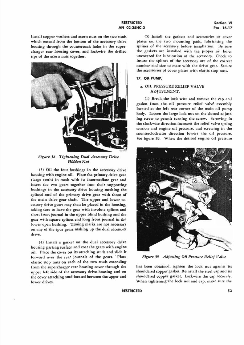
5/11/2018 Wright 2600 - slidepdf.com
http://slidepdf.com/reader/full/wright-2600 62/77
RESTRICTED
AN 02-35HC-2
Install copper washers and acorn nuts on the two studs
which extend from the bottom of the accessory drive
housing through the countersunk holes in the super-
charger rear housing cover, and lockwire the drilled
tips of the acorn nuts together.
Figure 38-Tighlening Dual Accessory Drive
Hidden Nul
(3) Oil the four bushings in the accessory drive
housing with engine oil. Place the primary drive gear
(large teeth) in mesh with its intermediate gear andinsert the two gears together into their supporting
bushings in the accessory drive housing meshing the
splined end of the primary drive gear with those of
the main drive gear shaft. The upper and lower ac-
cessory drive gears may then be placed in the housing,
taking care to have the gear with involute splines and
short front journal in the upper blind bushing and the
gear with square splines and long front journal in the
lower open bushing. Timing marks are not necessary
on any of the spur gears making up the dual accessory
drive.
(4) Install a gasket on the dual accessory drive
housing parting surface and coat the gears with engine
oil. Place the cover on its attaching studs and slide it
forward over the rear journals of the gears. ' Place
elastic stop nuts on each of the two studs extending
from the supercharger rear housing cover through the
upper left side of the accessory drive housing and on
the cover attaching stud located between the upper and
lower drives.
RESTRICTED
Sectio
Par.
(5) Install the gaskets and accessories or
plates on the two mounting pads, lubricating
splines of the accessory before installation, Be
the gaskets are installed with the proper oil
uncovered for lubrication of the accessory. Chec
insure the splines of the accessory are of the co
number and size to mate with the drive gear. S
the accessories of cover plates with elastic stop nu
17. OIL PUMP.
a. OIL PRESSURE RELIEF VALVE
ADJUSTMENT.
(1) Break the lock wire and remove the cap
gasket from the oil pressure relief valve asse
located at the left rear corner of the main oil p
body. Loosen the large lock nut on the slotted ad
ing screw to permit turning the screw. Screwingthe clockwise direction increases the relief valve sp
tension and engine oil pressure, and screwing in
counterclockwise direction lowers the oil pres
See figure 39. When the desired engine oil pre
Figure 39-Adjmlillg Oil Pressure Relief V'al
has been obtained, tighten the lock nut agains
shouldered copper gasket. Reinstall the steel cap an
shouldered copper gasket. Lockwire the cap secu
When righrening-the lock rrut and cap, make sure
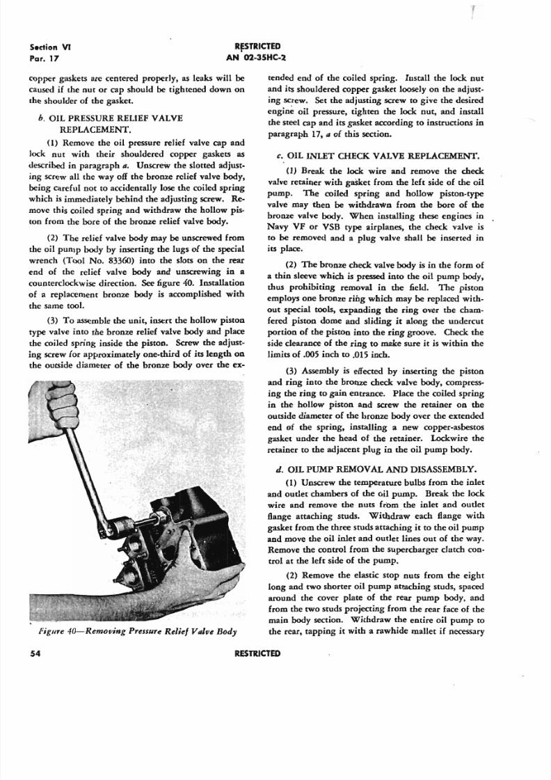
5/11/2018 Wright 2600 - slidepdf.com
http://slidepdf.com/reader/full/wright-2600 63/77
S.dion VI
Par. 17
R~TRICTED
AN 02-35HC-2
copper gaskets are centered properly, as leaks will be
caused if the nut or cap should be tightened down on
the shoulder of the gasket.
h. OIL PRESSURE REUEF VALVE
REPLACEMENT.
(1) Remove the oil pressure relief valve cap and
lock nut with their shouldered copper gaskets as
described in paragraph a. Unscrew the slotted adjust-
ing screw all the way off the bronze relief valve body,
being careful not to accidentally lose the coiled spring
which is immediately behind the adjusting screw. Re-
move this coiled spring and withdraw the hollow pis-
ton from the bore of the bronze relief valve body.
(2) The relief valve body may be unscrewed from
the oil pump body by inserting the lugs of the special
wrench (Tool No. 83360) into the slots on the rear
end of the relief valve body and unscrewing in a
counterclockwise direction. See figure 40. Installation
of a replacement bronze body is accomplished with
the same tool.
(3) To assemble the unit, insert the hollow piston
type valve into the bronze relief valve body and place
the coiled spring inside the piston. Screw the adjust-
ing screw for approximately one-third of its length on
the outside diameter of the bronze body over the ex-
Figure 40-Renwving Pressure Relief Valve Body
54
tended end of the coiled spring. Iustall the lock nut
and its shouldered copper gasket loosely on the adjust-
ing screw. Set the adjusting screw to give the desired
engine oil pressure, tighten the lock nut, and install
the steel cap and its gasket according to instructions in
paragraph 17. a of this section.
c. OIL INLET CHECK. VALVE REPLACEMENT.
(1) Break the lock wire and remove the check
valve retainer with gasket from the left side of the oil
pump. The coiled spring and hollow piston-type
valve may then be withdrawn from the bore of the
bronze valve body. When installing these engines in
Navy VF or VSB type airplanes, the check valve is
to be removed and a plug valve shall be inserted in
its place.
(2) The bronze check valve body is in the form of
a thin sleeve which is pressed into the oil pump body,
thus prohibiting removal in the field. The piston
employs one bronze rw.g which may be replaced with-
out special tools, expanding the ring over the cham-
fered piston dome and sliding it along the undercut
portion of the piston into the ring groove. Check the
side clearance of the ring to make sure it is within the
limits of .005 inch to .015 inch.
(3) Assembly is effected by inserting the piston
and ring into the bronze check valve body. compress-
ing the ring to gain entrance. Place the coiled spring
in the hollow piston and screw the retainer on theoutside diameter of the bronze body over the extended
end of the spring, installing a new copper-asbestos
gasket under the head of the retainer. Lockwire the
retainer to the adjacent plug in the oil pump body.
d. OIL PUMP REMOVAL AND DISASSEMBLY.
(1) Unscrew the temperature bulbs from the inlet
and oudet chambers of the oil pump. Break the lock
wire and remove the nuts from. the inlet and oudet
flange attaching studs. Withdraw each flange with
gasket from the three studs attaching it to the oil pump
and move the oil inlet and outlet lines out of the way.
Remove the control from the supercharger clutch con-
trol at the left side of the pump.
(2) Remove the elastic stop nuts from the eight
long and two shorter oil pump attaching studs, spaced
around the cover plate of the rear pump body, and
from the two studs projecting from the rear face of the
main body section. Withdraw the entire oil pump to
the rear, tapping it with a rawhide mallet if necessary
RESTRICTED
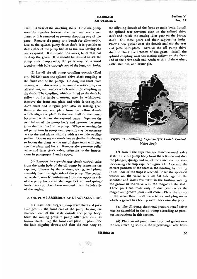
5/11/2018 Wright 2600 - slidepdf.com
http://slidepdf.com/reader/full/wright-2600 64/77
RESTRICTED
AN 02-35HC-2
Section
Par
until it is clear of the attaching studs. Hold the pump
assembly together between the front and rear cover
plates as it is removed to prevent dropping any of the
parts. Remove the pump to a bench for disassembly.
Due to the splined pump drive shaft, it is possible to
slide either of the pump bodies to the rear leaving the
gears exposed. If this condition arises, be careful not
to drop the gears. If it should be desired to set the
pump aside temporarily, the parts may be retained
together with bolts through two of the long stud holes.
(3) Insr-Il the oil pump coupling wrench (Tool
No. 800524) over the splined drive shaft coupling at
the front end of the pump. Holding the shaft from
turning with this wrench, remove the cotter pin, cas-
tellated nut, and washer which retain the coupling on
the shaft. The coupling, which is fitted to the shaft by
splines on its inside diameter, may be withdrawn.
Remove the front end plate and with it the splined
drive shaft and integral gear, also its mating gear.
Remove the rear end plate from the hollow dowels
which align the plate to the rear half of the pump
body and withdraw the exposed gears. Separate the
two halves of the pump body and remove the gears
from the front half of the pump. When separating the
oil pump into its component parts, it may be necessary
'0 tap the end plates slightly with a rawhide or fiber
mallet. Do not use a screwdriver or similar implement
to loosen the plates as the use of these tools will dam-
age the plate and body. Remove the pressure relief
valve and inlet check valve, referring to the instruc-
tions in paragraphs b and c above.
(4) Remove the supercharger clutch control valve
from the main body of the oil pump by removing the
cap nut, followed by the retainer, spring, and piston
assembly from the right side of the pump. The control
valve shaft may be withdrawn from the opposite side
of the pump body after the large lock nut and spring-:
loaded stop nut have been removed from the left side
of the engine.
e. OIL PUMP ASSEMBLY AND INSTALLATION.
(l) Install the integral pump drive shaft and pres-
sure gear in the front end of the pump having the
threaded end of the shaft outside the pump body.
Slide the mating pressure pump idler gear over its
bronze shaft. Tap the front end plate in place over
the hole aligning dowels and then the rear body on
the aligning dowels of the front or main body. In
the splined rear scavenge gear on the splined d
shaft and install the mating idler gear on the bro
shaft. Oil these gears and their supporting h
Place' a new gasket over the dowels and tap the
end plate into place. Revolve the oil pump dshaft to check the freeness of the gears. Install
splined coupling over the mating splines on the f
end of the drive shaft and retain with a plain wa
castellated nut, and cotter pin.
Figure 41-Inslalling Supercharger Clutcb Con
Valve Shaft
(2) Install the supercharger dutch control
shaft in the oil pump body from the left side and
the plunger, spring, and cap of the clutch control
lockwiring the stop cap. See figure 41. Ascertain
correct position of the shaft in the housing by tur
it until one of the stops is reached. Place the sphe
washer on the valve with its Bat side against
shoulder and insert the valve in the bushing m
the groove in the valve with the tongue of the s
These parts can mate only in one position as
tongue and groove joint is off center. Place the sp
in the valve, then install the retainer and plug u
which a gasket has been placed. Lockwire the pl
(3) The oil pump check and pressure relief v
may be assembled in the oil pump according to p
ous instructions in this section.
(4) Place an oil pump mounting pad gasket
the ten attaching studs in the supercharger rear
RESTRICTED
5/11/2018 Wright 2600 - slidepdf.com
http://slidepdf.com/reader/full/wright-2600 65/77
Section VI
Par. 17-21
RESTRICTED
AN 02-35HC-2
Figure 42---CluI&b Control '"sl,.udion PWe
ing cover making sure the oil vent hole for the oil
pump relief valve drain passage is not blocked. Coat
the oil pump drive shaft coupling with petrolatum,Specification AN-VV·P-236. and install the pump over
the attaching studs, meshing the coupling with the
splined end of the drive shaft in the supercharger rear
housing cover. Install plain washers, castellated nuts,
and cotter pins on each of the eight long and two short
attaching studs. Tighten the nuts to a torque of 85
to 100 inch pounds.
(5) Install the oil inlet and outlet lines over the
three attaching studs at each connection in the oil
pump body, placing a gasket under the attaching
flanges. Secure the flanges with castellated nuts and
cotter pins. Screw the temperature bulbs into their
bushings in the oil inlet and outlet chambers of the
oil pump if used.
18. Oil SCREEN REPLACEMENT.
II. The oil screen is attached to the left side of the
supercharger rear housing just below the gun synchro-
nizer drives.
b. Remove the elastic stop nuts securing the oil
screen cover and retainer to the eight attaching studs.
Remove the cover and retainer. If the retainer shouldbe sruck, tap it lighdy on its sides with a rawhide
mallet to loosen ir, Withdraw the oil screen.
c. Install the oil screen in the supercharger rear hous-
ing inserting the flat end first. Place a new gasket on
the oil screen cover mounting Range and install the
cover and retainer. Secure the cover with elastic stop
nuts.
56
19. SUPERCHARGER DRAIN VAlVE.
II. REMOV AL-Discoooect the drain line from the
outlet coooection in the drain valve housing. Break
the lock wire securing the valve housing to the super-
charger rear housing, and unscrew the valve housing
from the valve body. Take care not to drop the piston
and disk unit which may remain either with the valve
body or in the valve housing. Remove the piston and
disk unit. Using a wrench, unscrew the valve body
from the supercharger rear housing, and withdraw
the body and tube assembly as a unit,
b. INSTALLATION.
(1) Install two new rubber packing rings in the
groove at the small end of the valve body and one
below the flange at the large end. If the drain valve
is not assembled, place the piston and disk unit on the
valve body and assemble the housing.
(2) Insert the complete assembly in the super-
charger rear housing, using a washer between the
Range on the valve body and the supercharger rear
housing. Lockwire the drain valve housing to the
supercharger rear housing and install the drain valve
in the valve housing outlet,
20. CRANKCASE BREATHER.
4. Two crankcase breather vent connections are lo-
cated on the front supercharger housing between the
intake pipes of cylinders No. 14 and 1 and No.2 and
3. Elastic stop nuts secure the drilled attaching {lange
of each breather connection to four studs in the super·
charger front housing. See figure 43.
b.When removing either breather connection, with-
draw it straight outwards from its mounting pad to
avoid damaging the oval tube which extends from the
bottom of the breather connection for approximately
1-3/4 inch into the front supercharger housing.
c. The screen which is pressed into the mouth of the
breather connection should not be removed for ordi-
nary cleaning purposes.
21. SUPERCHARGER Oil SEAl VENT.
4. The supercharger oil seal atmosphere vent con-
sists of a hole leading from the space between the
middle two rings of the rear impeller shaft oil seal
sleeve, through the rear wall of the induction passage
to the discharge assembly mounting flange at the top
of the rear supercharger housing. The hole at the
mouting ftange end indexes with a hole in the rear
RESTRICTED
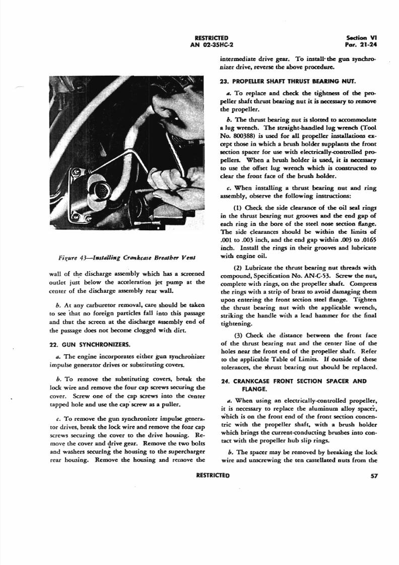
5/11/2018 Wright 2600 - slidepdf.com
http://slidepdf.com/reader/full/wright-2600 66/77
RESTRICTEDA N 02-35HC-2
Fis:ure 43-lmlillli,.g C,._kcase Brelllher VenI
wall of the discharge assembly which has a screened
outlet just below the acceleration jet pump at the
center of the discharge assembly rear wall.
h. At any carburetor removal, care should be taken
to see that no foreign particles fall into this passage
and that the screen at the discharge assembly end of
the passage does not become clogged with dirt.
22. G U N S YN CH RO NIZE RS .
a; The engine incorporates either gun synchronizer
impulse generator drives or substituting covers.
h. To remove the substituting covers, break the
lock wire and remove the four cap screws securing the
cover. Screw one of the cap screws into the center
tapped hole and use the cap screw as a puller.
c. To remove the gun synchronizer impulse genera-
tor drives, break the lock wire and remove the four cap
screws securing the cover to the drive housing. Re-
move the cover and ~cive gear. Remove the two bolts
and washers securing the housing to the supercharger
rear housing. Remove the housing and remove the
SectionPar. 21
intermediate drive gear. To install· the gun sync
nizer drive, reverse the above procedure.
23. PR O PE llE R SH A FT TH R U ST B EA R IN G N U T .
II. To replace and check the tightness of the
peller shaft thrust bearing nut it is necessary to rem
the propeller.
h. The thrust bearing nut is slotted to accomnvx
a lug wrench. The straight-handled lug wrench (T
No. 800388) is used for all propeller installations
cept those in which a brush holder supplants the f
section spacer for use with electrically-controlled
pellers. When a brush holder is used, it is neces
to use the offset lug wrench which is c :onst ruc ted
clear the front face of the brush holder.
c. When installing a thrust bearing nut and
assembly, observe the following instructions:
( I) Check the side clearance of the oil sea l r
in the thrust bearing nut grooves and the end gap
each ring in the bore of the steel nose section fla
The side clearances should be within the limits
.001 to .003 inch, and the end gap within .003 to .0
inch. Install the rings in their grooves and lubri
with engine oil
(2) Lubricate the thrust bearing nut threads w
compound, Specification No. AN-C-53. Screw the
complete with rings, on the propeller shaft. Comp
the rings with a strip of brass to avoid damaging t
upon entering the front section steel Bange. Tigh
the thrust bearing nut with the applicable wren
striking the handle with a lead hammer for the
tightening.
(3) Check the distance between the front
of the thrust bearing nut and the center line of
holes near the front end of the propeller shaft. R
to the applicable Table of Limits. If outside of t
tolerances, the thrust bearing nut should be repla
24. C RA N KC A SE FRO N T SE CT IO N SPA C ER A N D
F L A N G E .
II. When using an electrically-controlled prope
it is necessary to replace the aluminum alloy sp
which is on the front end of the front section con
tric with the propeller shaft, with a brush ho
which brings the current-conducting brushes into
tact with the propeller hub slip rings.
h. The spacer may be removed by breaking the
wire and unscrewing the ten castellated nuts from
RES TR ICTED
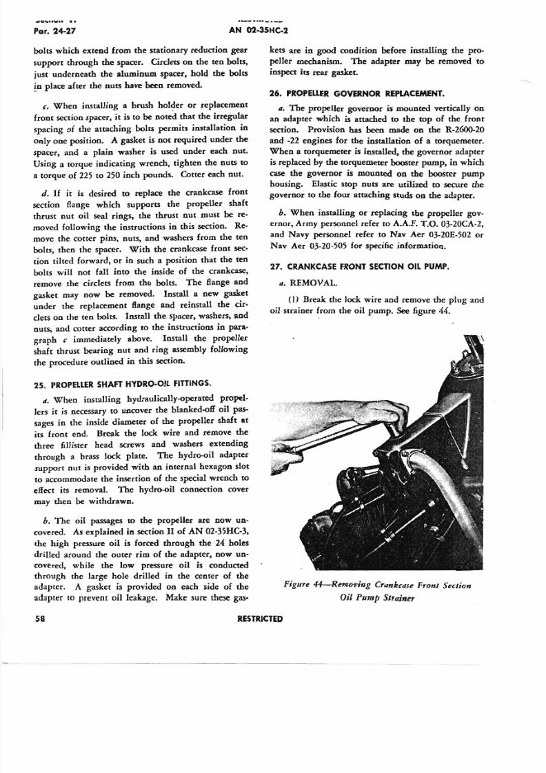
5/11/2018 Wright 2600 - slidepdf.com
http://slidepdf.com/reader/full/wright-2600 67/77
Par. 24-27 A N 02-35HC-2
bolts which extend from the stationary reduction gear
support through the spacer. Circlets on the ten bolts,
just underneath the aluminum spacer, hold the bolts
.!n place after the nuts have been removed.
c. When installing a brush holder or replacement
front section spacer, it is to be noted that the irregular
spacing of the attaching bolts permits installation in
only one position. A gasket is not required under the
spacer, and a plain washer is used under each nut.
Using a torque indicating wrench, tighten the nuts to
a torque of 225 to 250 inch pounds. Cotter each nut.
d. If it is desired to replace the crankcase front
section flange which supports the propeller shaft
thrust nut oil seal rings, the thrust nut must be re-
moved following the instructions in this section. Re-
move the cotter pins, nuts, and washers from the ten
bolts, then the spacer. With the crankcase front sec-
tion tilted forward, or in such a position that the ten
bolts wilJ not fall into the inside of the crankcase,
remove the circlets from the bolts. The flange and
gasket may now be removed. Install a new gasket
under the replacement Bange and reinstall the cir-
clets on the ten bolts. Install the spacer, washers, and
nuts, and cotter according to the instructions in para-
graph c immediately above. Install the propeller
shaft thrust bearing nut and ring assembly following
the procedure outlined in this section.
25. PR OPEL LER SH AFT H YD RO -O IL F ITT IN GS .
It. When installing hydraulically-operated propel-
lers it is necessary to uncover the blanked-off oil pas-
sages in the inside diameter of the propeller shaft at
its front end. Break the lock wire and remove the
three fillister head screws and washers extending
through a brass lock plate. The hydro-oil adapter
support nut is provided with an internal hexagon slot
to accommodate the insertion of the special wrench to
effect its removal. The hydro-oil connection cover
may then be withdrawn.
h. The oil passages to the propeller are now un-
covered. As explained in section II of AN 02-35HC-3,
the high pressure oil is forced through the 24 holes
drilled around the outer rim of the adapter, now un-
covered, while the low pressure oil is conducted
through the large hole drilled in the center of the
adapter. A gasket is provided on each side of the
adapter to prevent oil leakage. Make sure these gas-
kets are in good condition before installing the pro-
peller mechanism. The adapter may be removed to
inspect its rear gasket.
26. PR OPEL LER G OV ER NO R REPLA CE M EN T .
It. The propeller governor is mounted vertically on
an adapter which is attached to the top of the front
section. Provision hasbeen
made on the R-2600-20
and -22 engines for the installation of a torquemeter.
When a torquemeter is installed, the governor adapter
is replaced by the torquemeter booster pump, in which
case the governor is mounted on the booster pump
housing. Elastic stop nuts are utilized to secure the
governor to the four attaching studs on the adapter.
h. When installing or replacing the propeller gov-
ernor, Army personnel refer to A.A.F. T.O. 03-20CA-2,
and Navy personnel refer to Nav Aer 03-20E-502 or
Nav Aer 03-20-505 for specific information.
27. CR A NKCA SE FR O NT SE CT IO N O IL PUM P.
It. REMOVAL
(1) Break the lock wire and remove ·the plug and
oil strainer from the oil pump. See figure 44.
Figure 44-Removing Crltnk~ase Front Section
Oil Pump Strainer
58 RESTR ICTED
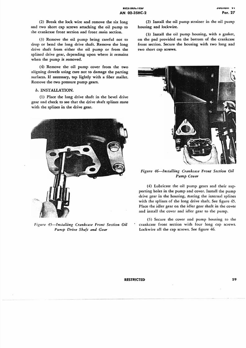
5/11/2018 Wright 2600 - slidepdf.com
http://slidepdf.com/reader/full/wright-2600 68/77
K~ I KI'- I ~., .,,,, ..
PN 02-35HC-2
(2) Break the lock wire and remove the six long
and two short cap screws attaching the oil pump to
the crankcase front section and front main section.
(3) Remove the oil pump being careful not to
drop or bend the long drive shaft. Remove the long
drive shaft from either the oil pump or from the
splined drive gear, depending upon where it remains
when the pump is removed.
(4) Remove the oil pump cover from the two
aligning dowels using care not to damage the parting
surfaces. If necessary, tap lightly with a fiber mallet.
Remove the two pressure pump gears.
b. INSTALLATION.
(1) Place the long drive shaft in the bevel drive
gear and check to see that the drive shaft splines mate
with the splines in the drive gear.
Figure 45-lnslalling Crankcase Front Section Oil
Pump Drive Shall and Gear
(2) Install the oil pump strainer in the oil p
housing and lockwire.
n) Install the oil pump housing, with a g
on the pad provided on the bottom of the cran
front section. Secure the housing with two long
two short cap screws.
Figure 46-Inslalling Crankcase Front Section
Pump Cover
(4) Lubricate the oil pump gears and their
porting holes in the pump and cover. Install the
drive gear in the housing, mating the internal s
with the splines of the long drive shaft. See figu
Place the idler gear on the idler gear shaft in the
and install the cover and idler gear to the pump
(5) Secure the cover and pump housing
crankcase front section with four long cap s
Lockwire all the cap screws. See figure 46.
RESTPJCTED
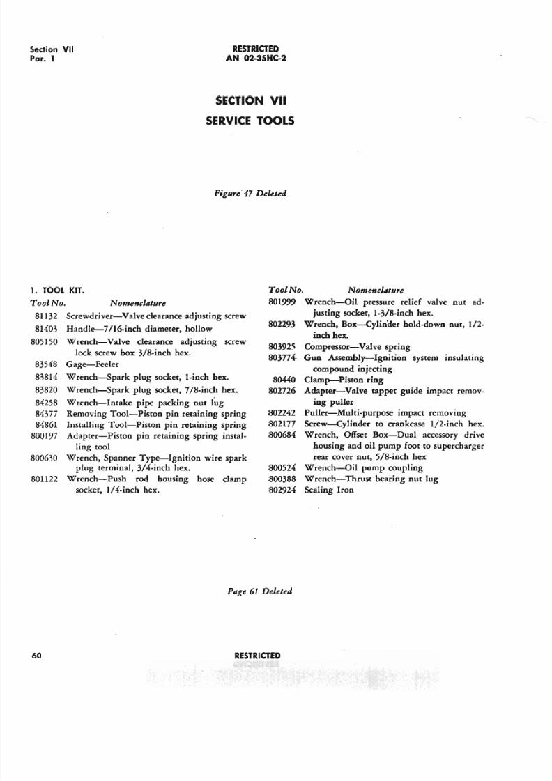
5/11/2018 Wright 2600 - slidepdf.com
http://slidepdf.com/reader/full/wright-2600 69/77
Section VII
Par. 1
R E S T R I C T E D
AN 02-35HC-2
SECTION VII
SERVICE TOOLS
Figure'47 Deleted
1. TOOL KIT .
Tool No. Nomenclature
81132 Screwdriver-Valve clearance adjusting screw
81403 Handle-7/H)·inch diameter, hollow
805150 Wrench-Valve clearance adjusting screw
lock screw box 31B-inch hex.
83548 Gage-Feeler
83814 Wrench-Spark plug socket, l-Inch hex.
83820 Wrench-Spark plug socket, 7/M·inch hex.
84258 Wrench-Intake pipe packing nut lug
84377 Removing Tool-Piston pin retaining spring
84861 Installing Tool-Piston pin retaining spring
800197 Adapter-Piston pin retaining spring instal-
ling tool
800630 Wrench, Spanner Type-Ignition wire spark
plug terminal, 3/4-inch hex.
801122 Wrench-Push rod housing hose clamp
socket, l/4-inch hex.
Tool No.
801999
802293
80392~
803774-
80440
802726
802242
802177
800684
800524
800388
802924
Page 61 Deleted
60 R E S T R I C T E D
Nomenclature
Wrench-Oil pressure relief valve nut ad-
justing socket, 1-31B-inchhex.
Wrench, Box-Cylin<Ier hold-down nut, 1/2-
inch hex.
Compressor-Valve spring
Gun Assembly-Ignition system insulating
compound injecting
Clamp-Piston ring
Adapter-Valve tappet guide impact remov-
ing puller
Puller-Multi-purpose impact removing
Screw-Cylinder to crankcase II2-inch hex.
Wrench, Offset Box-Dual accessory drive
housing and oil pump foot to supercharger
rear cover nut, 5/8-inch hex
Wrench-Oil pump coupling
Wrench-Thrust bearing nut lug
Sealing Iron
5/11/2018 Wright 2600 - slidepdf.com
http://slidepdf.com/reader/full/wright-2600 70/77
RESTRJCTED
AN 02-35HC-2
RESTRICTED
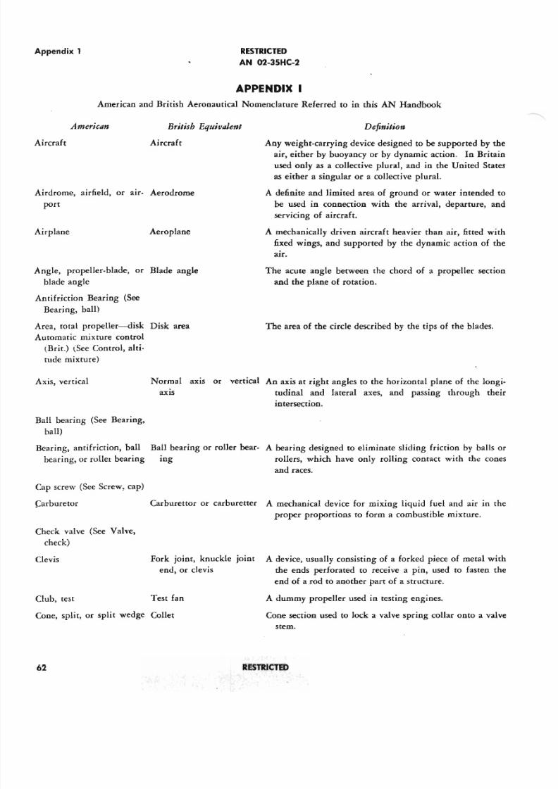
5/11/2018 Wright 2600 - slidepdf.com
http://slidepdf.com/reader/full/wright-2600 71/77
Appendix 1 RESTRICTED
AN 02-35HC-2
APPENDIX I
American and British Aeronautical Nomenclature Referred to in this AN Handbook
American British Equivalent
Aircraft
Definition
Any weight-carrying device designed to be supported by the
air, either by buoyancy or by dynamic action. In Britain
used only as a collective plural, and in the United States
as either a singular or a collective plural.
A definite and limited area of ground or water intended to
be used in connection with the arrival, departure, and
servicing of aircraft.
A mechanically driven aircraft heavier than air, fitted with
fixed wings, and supported by the dynamic action of the
au.
Aircraft
Airdrome, airfield, or arr- Aerodrome
port
Airplane Aeroplane
Angle, propeller-blade, or Blade angle
blade angle
Antifriction Bearing (See
Bearing, ball)
Area, total propeller-s-disk Disk area
Automatic mixture control
(Br it.) (See Control, alti-
tude mixture)
The acute angle between the chord of a propeller section
and the plane of rotation.
The area of the circle described by the tips of the blades.
Axis, vertical Normal axis or vertical An axis at right angles to the horizontal plane of the longi-
axis tudinal and lateral axes, and passing through their
intersection.
Ball bearing (See Bearing,
ball)
Bearing, anti friction, ball
bearing, or rol ler bearing
Ball bearing or roller bear- A bearing designed to eliminate sliding friction by balls or
ing rollers, which have only rolling contact with the cones
and races.
Cap screw (See Screw, cap)
Carburetor Carburettor or carburerter A mechanical device for mixing liquid fuel and air in the
proper proportions to form a combustible mixture.
Check valve (See Valve,
check)
Clevis Fork joint, knuckle joint A device, usually consisting of a forked piece of metal with
end, or clevis the ends perforated to receive a pin, used to fasten the
end of a rod to another part of a structure.
Test fan A dummy propeller used in testing engines.lub, test
Cone, split, or split wedge Collet Cone section used to lock a valve spring collar onto a valve
stem.
62 RESTRICTED
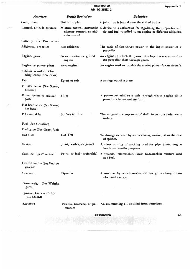
5/11/2018 Wright 2600 - slidepdf.com
http://slidepdf.com/reader/full/wright-2600 72/77
American
Cone, union
RESTRICTED
AN 02-3SHC-2
Append
Brilish Equivalent
Union nipple
Definilion
A joint that is brazed onto the end of a pipe.
Control, altitude mixture Mixture control, automatic A device on a carburetor for regulating the proportion
mixture control, or alti- air and fuel supplied to an engine at different alti
tude control
Cotter pin (See Pin, cotter)
Efficiency, propeller
Engine, geared
Engine or power plant
Exhaust manifold (See
Ring, exhaust collector)
Exit
Fillister screw (See Screw,
fillister)
Filter, screen or strainer
(oil)
Flat-head screw (See Screw,
flat-head)
Friction, skin
Fuel (See Gasoline)
Fuel gage (See Gage, fuel)
(to) Gall
Gasket
Gasoline, "gas," or fuel
Geared engine (See Engine,
geared)
Generator
Gross weight (See Weight,
gross)
Ignition harness (Brit.)
(See Shield)
Kerosene
Net efficiency
Geared motor or geared
engine
Aero-engine
Egress or exit
Filter
Surface friction
(to) Fret
The ratio of the thrust power to the input power
propeller.
An engine in which the power developed is transmitt
the propeller shaft through gears.
An engine used to provide the motive power for an air
A passage out of a place.
A porous material or a unit through which engine
passed to cleanse and strain it.
The tangential component of fluid force at a point
surface.
To damage or wear by an oscillating motion, as in th
of splines.
A sheet or ring of packing used for pipe joints, e
heads, and similar purposes.
Petrol or fuel (preferable) .i. volatile, inflammable, liquid hydrocarbon mixture
as a fuel.
Joint, washer, or gasket
Dynamo A machine by which mechanical energy is changed
electrical energy.
Paraffin, kerosene. or pc- An illuminating oil distilled from petroleum.
troleum
RESTRICTED
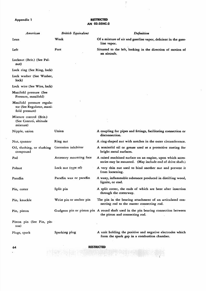
5/11/2018 Wright 2600 - slidepdf.com
http://slidepdf.com/reader/full/wright-2600 73/77
Appendix 1
Americlln British Equivalenl
Weakean
Left Port
Locknut (Brit.) (See Pal-
nut)
Lock ring (See Ring, lock)
Lock washer (See Washer,
lock)
Lock wire (See Wire, lock)
Manifold pressure (See
Pressure, manifold)
Manifold pressure regula-
tor (See Regulator, mani-
fold pressure)
Mixture control (Brir.)
(See Controi, altitude
mixture)
Nipple, union Union
Nut, spanner Ring nut
Oil, slushing, or slushing Corrosion inhibitor
compound
Pad Accessory mounting face
Palnut Lock nut (type of)
Paraffin Paraffin wax or paraffin
Pin, cotter Split pin
RESlRIClED
AN 02-35HC-2
Definition
Of a mixture of air and gasoline vapor, deficient in the gas0-
line vapor.
Situated to the left, looking in the direction of motion ofan aircraft.
A coupling for pipes and fittings, facilitating connection or
disconnection.
A ring-shaped nut with notches in the outer circumference.
A semisolid oil or grease used as a protective coating for
bright metal surfaces.
A raised machined surface on an engine, upon which acces-
sories may be mounted. (May include end of drive shaft.)
A very thin nut used to bind another nut and prevent it
from loosening.
A waxy, inflammable substance produced in distilling wood,
lignite, or coal.
A split cotter, the ends of which are bent after insertion
through the cotterway.
The pin in the bearing attachment of an articulated con-
necting rod to the master connecting rod.
Gudgeon pin or piston pin A round shaft used in the pin bearing connection between
the piston and connecting rod.
Pin, knuckle Wrist pin or anchor pin
Pin, piston
Piston pin (See Pin, pis-
ton)
Plugs, spark Sparking plug
64
A unit holding the positive and negative electrodes which
form the spark gap in a combustion chamber.
RESTR ICTS )
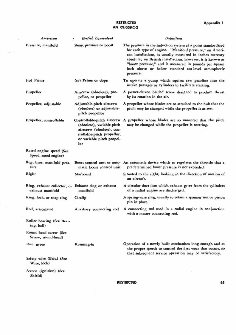
5/11/2018 Wright 2600 - slidepdf.com
http://slidepdf.com/reader/full/wright-2600 74/77
American
Pressure, manifold
(to) Prime
Propeller
Propeller, adjustable
Propeller, controllable
British EqUiflllknJ
Boost pressure or boost
(to) Prime or dope
Airscrew (obsolete), pro-
pellor, or propeller
AdjUStable-pitch airscrew
(obsolete) or adjustable-
pitch propellor
Controllable-pitch airscrew
(obsolete), variable-pitch
airscrew (obsolete), con-
trollable-pitch propeller,
or variable pitch propel-
lor
RESTRlCfED
AN 02-35HC-2
Append
Definilion
The pressure in the induction system at a point standard
for each type of engine. "Manifold pressure," on A
can installations, is usually measured in inches me
absolute; on British installations, however, it is know
"boost pressure," and is measured in pounds per s
inch above or below standard sea-level atmosp
pressure.
To operate a pump which squirts raw gasoline into
intake passages or cylinders to facilitate starting.
A power-driven bladed screw designed to produce t
by its rotation in the air.
A propeller whose blades are so attached to the hub tha
pitch may be changed while the propeller is at rest.
A propeller whose blades are so mounted that the
may be changed while the propeller is rotating.
Rated engine speed (See
Speed, rated engine)
Regulator, manifold pres- Boost control unit or auto- An automatic device which so regulates the throttle t
sure marie boost control unit predetermined boost pressure is not exceeded.
Right Starboard
Ring, exhaust collector, or Exhaust ring or exhaust
exhaust manifold manifold
Ring, lock, or snap ring
Rod, articulated
Roller bearing (See Bear-
ing, ball)
Round-head screw (SeeScrew, round-head)
Run, green
Safety wire (Brit.) (See
Wire, lock)
Screen (ignition) (See
Shield)
Situated to the right, looking in the direction of motioan aircraft.
A circular duct into which exhaust g?;es from the cyli
of a radial engine are discharged.
Circlip A spring-wire ring, usually to retain a spanner nut or p
pin in place.
Auxiliary connecting rod A connecting rod used in a radial engine in conjunc
with a master connecting rod.
Running-in Operation of a newly built mechanism long enough a
the proper speeds to control the first wear that occu
that subsequent service operation may be satisfacto
RESTRICTED
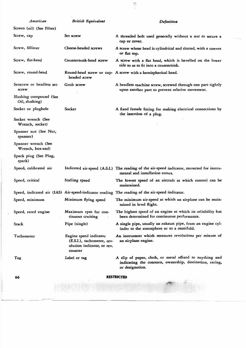
5/11/2018 Wright 2600 - slidepdf.com
http://slidepdf.com/reader/full/wright-2600 75/77
Ameri~lIn
Screen (oil) (See Filter)
Screw, cap
Screw, fillister
Screw, flat-head
Screw, round-head
Setscrew or headless set-
screw
Slushing compound (See
Oil, slushing)
Socket or plughole
Socket wrench (SeeWrench, socket)
Spanner nut (See Nut,
spanner)
Spanner wrench (See
Wrench, box-end)
Spack plug (See Plug,
spark)
Speed, calibrated au
Speed, critical
British Equivalent
Setscrew
Cheese-headed screws
Countersunk-head screw
Definition
A threaded bolt used generally without a nut to secure a
cap or cover,
A screw whose head is cylindrical and slotted, with a convex
or fiat top.
A screw with a fiat head, which is bevelled on the lowerside so as to fit into a countersink.
Round-head screw or cup- A screw with a hemispherical head.
headed screw
Grub screw
Socket
A headless machine screw, screwed through one part tightly
upon another part to prevent relative movement.
A fixed female fitting for making electrical connections by
the insertion of a plug.
Indicated air-speed (A.sl.) The reading of the air-speed indicator, corrected for instru-
mental and installation errors.
Stalling speed The lowest speed of an aircraft at which control can bemaintained.
Speed, minimum
Speed, indicated au (lAS) Air-speed-indicator reading The reading of the air-speed indicator.
Speed, rated engine
Stack
Tachometer
Tag
66
Minimum Bying speed
Maximum rpm for con-
tinuous cruising
Pipe (single)
Engine speed indicator
(E.s.l.), tachometer, rev-
olution indicator, or rev.
counter
Label or tag
The minimum air-speed at which an airplane can be main-
tained in level Bight.
The highest speed of an engine at which its reliability has
been determined for continuous performance.
A single pipe, usually an exhaust pipe, from an engine cyl-.
inder to the atmosphere or to a manifold.
An instrument which measures revolutions per minute of
an airplane engine.
A slip of paper. cloth. or metal affixed to anything and
indicating the contents, ownership, destination, rating,
or designation.
R E S T R I C T E D
. ' " " ' " ". ..
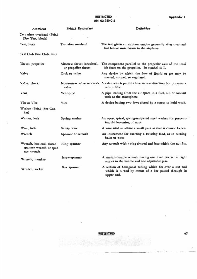
5/11/2018 Wright 2600 - slidepdf.com
http://slidepdf.com/reader/full/wright-2600 76/77
R E S T R I C T E D
AN 02-35HC-2
Appendi
AmericllfJ British Equivalent Definition
Test after overhaul (Brit.)
(See Test, block)
Test, block Test after overhaul The test given an airplane engine generally after overh
but before installation in the airplane.
Test Club (See Club, test)
Thrust, propeller Airscrew thrust (obsolete), The component parallel to the propeller axis of the t
or propeller thrust air force on the propeller. Its symbol is T.
Valve Cock or valve Any device by which the flow of liquid or ga s may
started, stopped, or regulated.
Non-return valve or check A valve which permits flow in one direction but preven
valve return flow.
Valve, check
Vise or Vice Vice
A pipe leading from the air space in a fuel, oil, or coo
tank to the atmosphere.
A device having two jaws closed by a screw to hold w
Vent Vent-pipe
Washer (Brit.) (See Gas-
ket)
Wrench, box-end, closed Ring spanner
spanner wrench or span-
ner wrench
An open, spiral, spring-tempered steel washer for prev
ing the loosening of nuts.
A wire used to secure a small pact so that it cannot loo
An instrument for exerting a twisting load, as in turn
bolts or nuts.
Any wrench with a ring-shaped end into which the nut
Washer, lock Spring washer
Wire, lock Safety wire
Wrench Spanner or wrench
Wrench, socketBox spanner
A straight-handle wrench having one fixed jaw set at
angles to the handle and one adjustable jaw.
A section of hexagonal tubing which fits over a nut
which is turned by means of a bar passed through
upper end.
W rench, monkeyScrew-spanner
RESTRI~
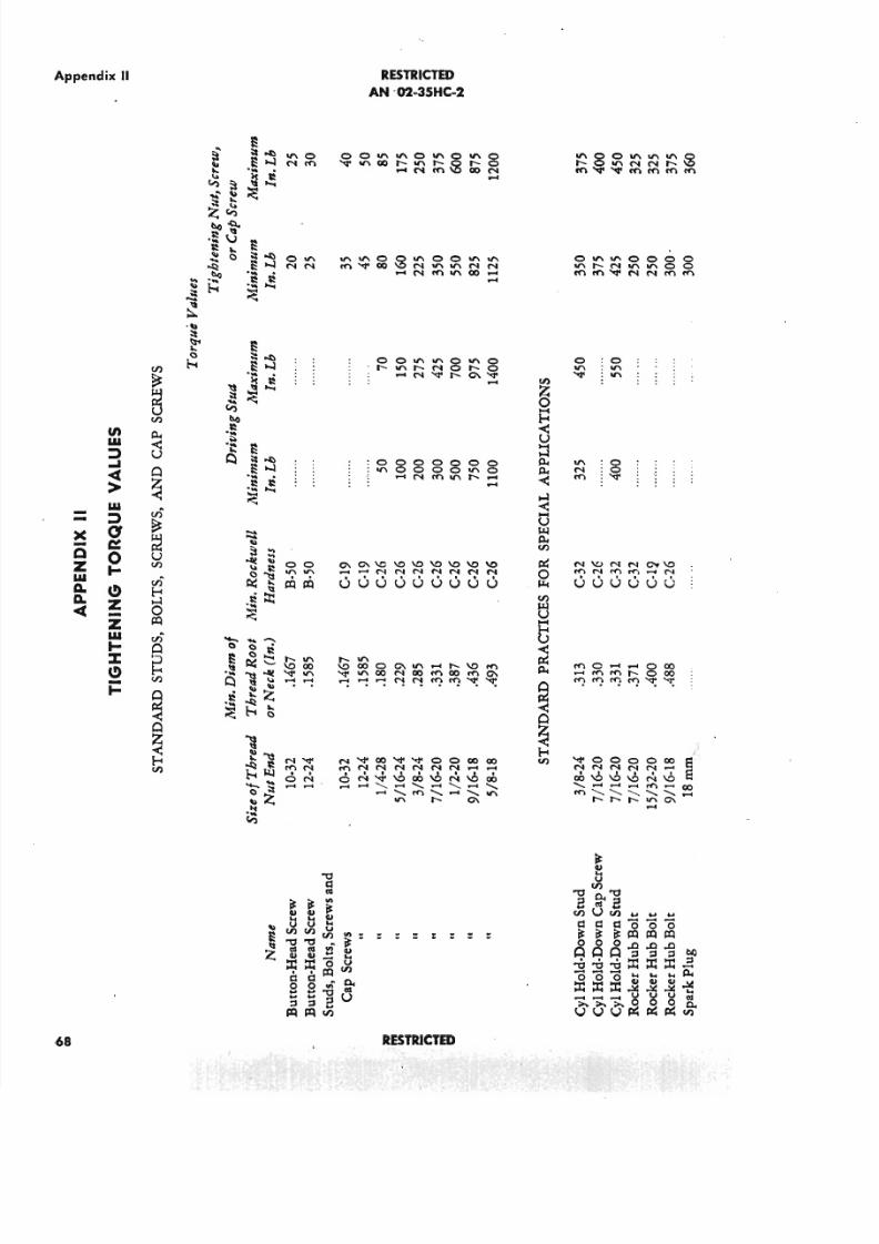
5/11/2018 Wright 2600 - slidepdf.com
http://slidepdf.com/reader/full/wright-2600 77/77
Appendix II
68
-(-QZIo U
A.D.~
enIo U:). . . .~>Io U
:)
a~o. . .ezZIo U
. . .: : z : :et =
o'"NN
'" 0NrO
r--'"\0 co
'< to '"- -
N<torI"IN
ON- -
RESTRICTED
AN -02-3SHC-2
~8888~8-NrO",r--_
. . . . . .
0\0\\0\0\0\0\0\0\0__ NNNNNNN
u u u u u u u u u
r--'"\OcooO\",_r--\OrO'<to "'co NCOrOCO rOO\
---<'!<'!~~~~
RESTRICTED
'" :0N:0rO :~
N\uNNOf\OrO N rI"IO ......
u u u u u u
rOo-_oco-rI"Irnr--oco
~~~~~~