wp
118
Water Surface Profiling by Eagle Point Information in this manual is subject to change without notice and does not represent a commitment on the part of the vendor. The software described in this manual is furnished under a license agreement and may be used or copied only in accordance with the terms of the agreement. Eagle Point has carefully prepared this program package, including research, development, and testing to ascertain its effectiveness and accuracy. However, no warranty of any kind is made with respect to this program package or its related material, except as may be expressly stated in the licensing agreement or other contractual document. In no event is Eagle Point liable for incidental or consequential damages in connection with, or arising out of, the furnishing, performance, or use of this program package. The installation program used to install Eagle Point software, InstallShield, is licensed software provided by InstallShield Software Corporation. ColorFast™, RoadCalc™, LANDCADD™, Virtual Simulator™, as well as the ColorFast™ and Eagle Point logos, are unregistered trademarks of Eagle Point. AutoCAD® is a registered trademark of Autodesk, Inc. MicroStation® is a registered trademark of Bentley Systems, Inc. Windows® and DOS® are registered trademarks of Microsoft Corporation. All other registered or unregistered trademarks are the property of their respective holders. Copyright © Q3, 2005, by Eagle Point. All rights reserved.
Transcript of wp

Water Surface Profiling by Eagle PointInformation in this manual is subject to change without notice and does not represent a commitment on the part of the vendor. The software described in this manual is furnished under a license agreement and may be used or copied only in accordance with the terms of the agreement.
Eagle Point has carefully prepared this program package, including research, development, and testing to ascertain its effectiveness and accuracy. However, no warranty of any kind is made with respect to this program package or its related material, except as may be expressly stated in the licensing agreement or other contractual document. In no event is Eagle Point liable for incidental or consequential damages in connection with, or arising out of, the furnishing, performance, or use of this program package.
The installation program used to install Eagle Point software, InstallShield, is licensed software provided by InstallShield Software Corporation.
ColorFast™, RoadCalc™, LANDCADD™, Virtual Simulator™, as well as the ColorFast™ and Eagle Point logos, are unregistered trademarks of Eagle Point.
AutoCAD® is a registered trademark of Autodesk, Inc.
MicroStation® is a registered trademark of Bentley Systems, Inc.
Windows® and DOS® are registered trademarks of Microsoft Corporation. All other registered or unregistered trademarks are the property of their respective holders.
Copyright © Q3, 2005, by Eagle Point. All rights reserved.


T A B L E
O F
C O N T E N T S
W A T E R S U R F A C E P R O F I L I N G
1 Concepts . . . . . . . . . . . . . . . . . . . . . . . . . .1Introduction . . . . . . . . . . . . . . . . . . . . . . . .2
Water Surface Profiling Features . . . . . . . . . . 2Installing HEC-RAS . . . . . . . . . . . . . . . . . .2
HEC-RAS Installation Procedures . . . . . . . . . . 3HEC-RAS Overview . . . . . . . . . . . . . . . . .7
Hydraulic Analysis Components . . . . . . . . . . . 9Steady Flow Water Surface Profiles . . . . . 9Unsteady Flow Simulation . . . . . . . . . . . . . 9Sediment Transport/Movable Boundary Computations . . . . . . . . . . . . . . . . . . . . . . 9
Previous Users of Eagle Point’s Water Surface Profiling Module . . . . . . . . . . . . .10
Converting Old Projects . . . . . . . . . . . . . . . . . 10Typical Project Flow . . . . . . . . . . . . . . . .12
2 Alignments . . . . . . . . . . . . . . . . . . . . . . .15Alignment Concepts . . . . . . . . . . . . . . . .16
Stream Alignment Definitions . . . . . . . . . . . . 16Cross-Section Alignment Definitions . . . . . . . 16Stream Alignments . . . . . . . . . . . . . . . . . . . . 17Overbank Alignments . . . . . . . . . . . . . . . . . . 17Cross-sectional Alignment . . . . . . . . . . . . . . . 18
Edit Alignment Data . . . . . . . . . . . . . . . . .19New PI . . . . . . . . . . . . . . . . . . . . . . . . . . . . . 21Modify PI . . . . . . . . . . . . . . . . . . . . . . . . . . . . 23Horizontal Curve Data . . . . . . . . . . . . . . . . . . 24Station Data . . . . . . . . . . . . . . . . . . . . . . . . . . 27Reference Station . . . . . . . . . . . . . . . . . . . . . 27Preview Alignment Graphics . . . . . . . . . . . . . 28Print Alignment Reports . . . . . . . . . . . . . . . . . 29
T a b l e o f C o n t e n t s i

Manage Alignments . . . . . . . . . . . . . . . . 30New Cross-Section Alignment . . . . . . . . . . . . 32
Associate Alignment . . . . . . . . . . . . . . . . 33Convert Objects to Stream Alignment . . . 35
QuickSteps . . . . . . . . . . . . . . . . . . . . . . . . . . . 36Convert Objects to Cross-Section Alignment . . . . . . . . . . . . . . . . . . . . . . . . 36
QuickSteps . . . . . . . . . . . . . . . . . . . . . . . . . . . 37Manage Utilities . . . . . . . . . . . . . . . . . . . 38
New Utility . . . . . . . . . . . . . . . . . . . . . . . . . . . 40Utility Annotation Settings . . . . . . . . . . . . . . . 41
View Alignment Graphics . . . . . . . . . . . . 44Synchronize Graphics and Data . . . . . . . 45
3 Cross-Sections . . . . . . . . . . . . . . . . . . . 47Cross-Sections Concepts . . . . . . . . . . . . 48
Cross-Section Types . . . . . . . . . . . . . . . . . . . 48Skewed Cross-Sections . . . . . . . . . . . . . . . . . 48Cross-Section Stationing . . . . . . . . . . . . . . . . 50Cross-Section Settings . . . . . . . . . . . . . . . . . . 51Import/Export Data . . . . . . . . . . . . . . . . . . . . . 51
Edit Cross-Section Data . . . . . . . . . . . . . 53New Stream Station . . . . . . . . . . . . . . . . . . . . 57Build Station List . . . . . . . . . . . . . . . . . . . . . . 58New Shot . . . . . . . . . . . . . . . . . . . . . . . . . . . . 59Query Cross-Section . . . . . . . . . . . . . . . . . . . 63
Extract Cross-Sections . . . . . . . . . . . . . . 64Global Surface Models . . . . . . . . . . . . . . . . . . 68
Annotate Cross-Sections . . . . . . . . . . . . 68Import Cross-Sections . . . . . . . . . . . . . . 70
Transfer Settings . . . . . . . . . . . . . . . . . . . . . . 71Transfer Settings – Import Tab . . . . . . . . . . . 71Transfer Settings – Export Tab . . . . . . . . . . . 72Transfer Settings – Editor Tab . . . . . . . . . . . . 74Assign Points to Station . . . . . . . . . . . . . . . . . 74
Export Cross-Sections . . . . . . . . . . . . . . 76Create User Formats . . . . . . . . . . . . . . . 77
New Format . . . . . . . . . . . . . . . . . . . . . . . . . . 78View Cross-Section Graphics . . . . . . . . . 79Cross-Section Settings . . . . . . . . . . . . . . 79
Cross-Section Settings – General Tab . . . . . . 80
i i W a t e r S u r f a c e P r o f i l i n g
Cross-Section Settings – Precision Tab . . . . 81Synchronize Graphics and Data . . . . . . .82
4 Transfer . . . . . . . . . . . . . . . . . . . . . . . . . .83Transfer Concepts . . . . . . . . . . . . . . . . . .84Export to HEC-RAS . . . . . . . . . . . . . . . . .84
Export to HEC-RAS Procedure . . . . . . . . . . . 86Import from HEC-RAS . . . . . . . . . . . . . . .89
Import from HEC-RAS Procedure . . . . . . . . . 90
5 Output . . . . . . . . . . . . . . . . . . . . . . . . . . .93Water Surface Profiles . . . . . . . . . . . . . . .94
Modify Profile . . . . . . . . . . . . . . . . . . . . . . . . . 96Water Surface Profile Settings . . . . . . . . . . . 96
Profile Settings – General Tab . . . . . . . . 96Define Coordinate System . . . . . . . . . . . 97Profile Settings – Sewer Display Tab . . . 98
Delineate Floodplain . . . . . . . . . . . . . . . .99Sub-project Prototype Settings . . . . . . .101
New Sub-project Prototype . . . . . . . . . . . . . 102
Index . . . . . . . . . . . . . . . . . . . . . . . . . . .105
T a b l e o f C o n t e n t s i i i

i v W a t e r S u r f a c e P r o f i l i n g

C H A P T E R
1
C O N C E P T SIn this chapter:
Introduction . . . . . . . . . . . . . . . . . . . . . . . . . . . . . . . . . . 2
Installing HEC-RAS. . . . . . . . . . . . . . . . . . . . . . . . . . . . 2
HEC-RAS Overview . . . . . . . . . . . . . . . . . . . . . . . . . . . 7
Previous Users of Eagle Point’s Water Surface Profiling Module10
Typical Project Flow . . . . . . . . . . . . . . . . . . . . . . . . . . 12
C h a p t e r 1 : C o n c e p t s 1

IntroductionThe Water Surface Profiling product allows you to develop stream alignments and cross-section data that then can be transferred to HEC-RAS. HEC-RAS is a Water Surface Profiling program developed by the U.S. Army Corps of Engineers Hydraulic Engineering Center that replaces HEC-2. This program allows you to perform one-dimensional steady flow calculations. After the river or stream is modeled in HEC-RAS, Water Surface Profiling imports the resultant data and create a profile of the river or stream. You can also create a floodplain delineation of the stream or river as well.
Eagle Point’s Water Surface Profiling product does not perform hydraulic computations by itself. You must have HEC-RAS installed. See Installing HEC-RAS (below) for information on how to install HEC-RAS.
Water Surface Profiling Features! Define Stream alignments (numerically or graphically)
! Define Cross-Section alignments (numerically or graphically)
! Input cross-section data by hand
! Extract original ground cross-section data from surface models or drawing elements
! Query and View original ground cross-sections
! Import/Export cross-section data in over 100 predefined formats with the ability to customize your own formats
! Export stream alignments and original ground cross-section data into HEC-RAS
Import results from HEC-RAS to:
! Draw multiple Water Surface Profiles from different flow scenarios in HEC-RAS
! Display water extents of each flow profile (floodplains)
! Display the Cross-Section boundary to indicate where contraction occurs due to hydraulic structures and bridges input through HEC-RAS
Installing HEC-RASThe installation of HEC-RAS contained on your Eagle Point CD is the full installation and provides all of the program files, help files, user and reference manuals, and example files that normally accompany the HEC-RAS program. The current version shipped and supported with Eagle Point is HEC-RAS 2.2.
2 W a t e r S u r f a c e P r o f i l i n g

Chapter 1: C
oncepts
" If you already have HEC-RAS version 2.2 installed on your machine you do not have toinstall the version included on the Eagle Point CD.
The HECRAS folder on the root of the CD contains the setup routine and sub folders that are needed to complete the installation of the HEC-RAS program. Three of the folders contain the written documentation for HEC-RAS. The manuals are stored in PDF format and require the Adobe Acrobat Reader to view. If you do not have a PDF viewer installed on your machine, you may install the reader from the Eagle Point CD Startup Kiosk.
The \HECRAS\USERMAN folder contains the HEC-RAS User's Manual, which explains how to use HEC-RAS. The user interface is described along with the underlying theory behind the program. A sample project is outlined, which works like a tutorial.
The \HECRAS\APPGUIDE folder contains the Applications Guide. This manual contains the text for the example projects that are stored in the HECRAS Data folder under the main RAS directory. Each of the examples is fully explained including the rationale for choosing certain options.
The \HECRAS\HYDREF folder contains the Hydraulic Reference Manual. This manual presents the theory and data requirements for hydraulic calculations in the HEC-RAS program. There is further discussion on modeling bridges, culverts, multiple openings, weirs, and spillways. Some of the optional capabilities are discussed as well, including bridge scour analysis and ice flow analysis.
HEC-RAS Installation Procedures This section outlines the steps that are needed to install the HEC-RAS program. You need to follow these procedures if you want to run Water Surface Profiling within Eagle Point.
" If you already have HEC-RAS version 2.2 installed on your machine you do not have to install the version included on the Eagle Point CD.
1. Close all Windows applications.2. Insert the CD into your CD-ROM drive (assumed D:).3. Run the SETUP.EXE file found in the \HECRAS folder on the CD-ROM.4. To run the setup program, click on the Windows Start button and select Run.5. Type D:\HECRAS\SETUP.EXE in the Run dialog box.6. Click on OK.
C h a p t e r 1 : C o n c e p t s 3

The Welcome screen of HEC-RAS Setup Wizard displays.
7. Click on Next to continue with the Setup program.The User Information dialog box (below) displays.
8. Type your name and the company you work for in the appropriate fields.9. Click on Next to accept the information and continue.
Figure 1-1 HEC-RAS 2.2 Installation Welcome Screen
Figure 1-2 User Information Dialog Box
4 W a t e r S u r f a c e P r o f i l i n g

Chapter 1: C
oncepts
The Choose Destination Location dialog box (below) displays.10. Choose the Destination Location. Click on Browse to select a location different from the default.
11. Click on Next to continue.The Select Program Folder dialog box (below) displays.
12. Enter the program folder in which you want the HEC-RAS icons to display or click on an existing folder from the list box.
13. Click on Next to continue.
Figure 1-3 Choose Destination Location Dialog Box
Figure 1-4 Select Program Folder Dialog Box
C h a p t e r 1 : C o n c e p t s 5

The Start Copying Files dialog box (below) displays.
14. Verify the Installation settings on the Start Copying Files screen. If they are correct, click on Next. If they are not correct, click on Back until you reach the options to change.The Setup Complete dialog box (below) shows the installation progress.
15. In the Setup Complete dialog box, toggle on the options that you want.16. Click on Finish.
Figure 1-5 Start Copying Files Dialog Box
Figure 1-6 Setup Complete Dialog Box
6 W a t e r S u r f a c e P r o f i l i n g

Chapter 1: C
oncepts
This completes the installation of the HEC-RAS program. You may run HEC-RAS at any time by selecting the icon from the Program Folder or when you complete the Export to HEC-RAS command in Water Surface Profiling.HEC-RAS OverviewThe Army Corps of Engineers’ replacement for HEC-2 is HEC-RAS. HEC-RAS is an acronym for the Hydrologic Engineering Center’s River Analysis System. This software allows you to perform one-dimensional steady flow analysis. In the future, Unsteady Flow and Sediment Transport will also be supported. One of the major advantages to using HEC-RAS is the new Windows interface. The entire program is dialog box-driven and gives you the ability to copy and paste data when needed. The program supports tabular entry of data and full 3-dimensional graphics. Below are examples of the interface.
The figure below shows the main menu in HEC-RAS. On this menu you can perform file management within HEC-RAS. You can have a project that may have many different Plans. A Plan has an associated Geometry and Flow data associated with it.
The HEC-RAS View Cross-Section dialog box (Figure 1-8 on page 8) shows an example of the cross-section view. HEC-RAS allows you to view your cross-sectional data
Figure 1-7 HEC-RAS Main Menu Dialog Box
C h a p t e r 1 : C o n c e p t s 7

graphically as well as modify it graphically. The Geometry Editor in HEC-RAS allows you to modify the cross-sectional data in a table.
Figure 1-9 (below) shows an example of the 3-Dimensional perspective plot. You can view the river system in a perspective view. HEC-RAS allows you to manipulate the scale of the view and rotation angles in the horizontal and vertical plan so you can change your view perspective.
Figure 1-8 HEC-RAS View Cross-Section Dialog Box
Figure 1-9 HEC-RAS X-Y-Z Perspective Plot Dialog Box
8 W a t e r S u r f a c e P r o f i l i n g

Chapter 1: C
oncepts
Hydraulic Analysis ComponentsThere are several Hydraulic Analysis Components, which include Steady Flow Water Surface Profiles, Unsteady Flow Simulation, and Sediment Transport/Movable Boundary Computations.
Steady Flow Water Surface ProfilesThis component of the modeling system is intended for calculating water surface profiles for steady gradually varied flow. The system can handle a full network of channels, a dendritic system, or a single river reach. The steady flow component is capable of modeling subcritical, supercritical, and mixed flow regime water surface profiles.
The basic computational procedure is based on the solution of the one-dimensional energy equation. Energy losses are evaluated by friction (Manning’s equation) and contraction/expansion (coefficient multiplied by the change in velocity head). The momentum equation is utilized in situations where the water surface profile is rapidly varied. These situations include mixed flow regime calculations (i.e., hydraulic jumps), hydraulics of bridges, and evaluating profiles at river confluences (stream junctions).
The effects of various obstructions such as bridges, culverts, weirs, and structures in the floodplain may be considered in the computations. The steady flow system is designed for application in floodplain management and flood insurance studies to evaluate flood way encroachments. Also, capabilities are available for assessing the change in water surface profiles due to channel improvements and levees.
Special features of the steady flow component include: multiple plan analyses; multiple profile computations; and multiple bridge and/or culvert opening analysis.
Unsteady Flow SimulationThis option is not available yet. This component of the HEC-RAS modeling system is capable of simulating one-dimensional unsteady flow through a full network of open channels. The unsteady flow equation solver is adapted from Dr. Robert L. Barkau’s UNET model (Barkau, 1992 and HEC, 1993). This unsteady flow component was developed primarily for subcritical flow regime calculations.
The hydraulic calculations for cross-sections, bridges, culverts, and other hydraulic structures that were developed for the steady flow component are incorporated into the unsteady flow module. Additionally, the unsteady flow component has the ability to model storage areas, navigation dams, tunnels, pumping stations, and levee failures.
Sediment Transport/Movable Boundary ComputationsThis option is not available yet. This component of the modeling system is intended for the simulation of one-dimensional sediment transport/movable boundary calculations
C h a p t e r 1 : C o n c e p t s 9

resulting from scour and deposition over moderate time periods (typically years, although applications to single flood events are possible).
The sediment transport potential is computed by grain size fraction, thereby allowing the simulation of hydraulic sorting and armoring. Major features include the ability to model a full network of streams, channel dredging, various levee and encroachment alternatives, and the use of several different equations for the computation of sediment transport.
The model is designed to simulate long-term trends of scour and deposition in a stream channel that might result from modifying the frequency and duration of the water discharge and stage, or modifying the channel geometry. This system can be used to evaluate deposition in reservoirs, design channel contractions required to maintain navigation depths, predict the influence of dredging on the rate of deposition, estimate maximum possible scour during large flood events, and evaluate sedimentation in fixed channels.
For more information on HEC-RAS and its modeling methods, refer to the Hydraulic Reference Manual and the Applications Guide electronic documentation on the Eagle Point CD.
Previous Users of Eagle Point’s Water Surface Profiling Module
This version of Water Surface Profiling represents a major change from what Eagle Point has done in the past with respect to Water Surface Profiling. No longer is Eagle Point performing the hydraulic computations of the water surface profile. The program now allows you to create stream alignments, cross-section alignments and extract them, transfer the data to HEC-RAS, read the water surface profile data from HEC-RAS and create water surface profiles in CAD. All of the computations for the hydraulics are done by HEC-RAS.
Because of the reliance of HEC-RAS for the hydraulic calculations, Eagle Point no longer directly interacts with HEC-2. You are able to translate the cross-section data to HEC-2, however. The HEC-2 program is included in the Eagle Point Program directory so you can still run it manually. Keep in mind that HEC-2 is superseded by HEC-RAS and that the U.S. Army Corps of Engineers highly recommends using HEC-RAS instead of HEC-2 for any new projects.
Converting Old ProjectsThe Water Surface Profiling projects in EP 7.0s, EP 13, EP14, and EP99/2000 can be converted to run in the new EP 2000 version of Water Surface Profiling. An important note to be aware of is that only the alignment and cross-section data is converted. In EP
1 0 W a t e r S u r f a c e P r o f i l i n g

Chapter 1: C
oncepts
7.0s, EP 13, EP14, and EP 99/2000, the cross-section data was oriented left-to-right as if you were looking upstream. This is not the normal convention for HEC-RAS. In EP 2000 Water Surface Profiling, the cross-sections are oriented left-to-right as you are looking downstream.Because of the new interaction with HEC-RAS, Water Surface Profiling in EP 2000 does not have a different hydraulic calculation engine as in previous releases. All of the calculations are performed in HEC-RAS. If you have existing water surface profiles created, Eagle Point updates the profile drawings so that the profile data from HEC-RAS can be drawn in them. The structure data (culverts, bridges, and weirs) are not written to the profile. The water surface profile, channel invert, and the overbank profiles are written to the drawing/design file.
Conversion of previous projects is automatic when you are using the Convert Previous Projects command. For EP 13, 14, and EP 99/2000 Water Surface Profiling versions, all of the sub-projects are converted. The EP 7.0 Water Surface Profiling projects did not have sub-projects like the later versions did. In that case, you had one stream/reach per project. The 7.0 projects are converted when the sub-project is opened. You need to make sure the drawing/design file name is the same as the project name was in EP 7.0 in order for the data to be converted. Only the cross-sections are converted, since there were no alignments in EP 7.0. See Convert Previous Projects in the Getting Started manual for more information.
C h a p t e r 1 : C o n c e p t s 1 1

Typical Project FlowBecause the computational portion of the program is performed in HEC-RAS, there is a need to transfer between Water Surface Profiling and HEC-RAS. The flow chart below outlines the typical project flow in Eagle Point as you work on a sub-project.
Water Surface Profiling works with the following assumptions.
! One sub-project can only contain one stream centerline (reach).
! Stream Stationing runs upstream with the Beginning of Project Station the most downstream point.
! Cross-Sections are viewed left-to-right as you look downstream.
! Cross-Section alignments must touch or cross your stream centerline.
Figure 1-10 Water Surface Profiling Typical Project Flow Chart
1 2 W a t e r S u r f a c e P r o f i l i n g

Chapter 1: C
oncepts
All of the alignment data can be entered either graphically or by entering the data through a dialog box interface. Use the Convert Objects to Stream Alignment command or enter the numeric data using the Edit Alignment Data command. Cross-section alignments can be defined graphically or numerically as well.The cross-sections can be extracted from a surface model (DTM) or directly entered into the dialog boxes.
After the data is entered for the alignment and cross-sections, the data is transferred to HEC-RAS using the Export to HEC-RAS command. Once the data file is created, you import the HEC-RAS data into HEC-RAS using the Import Geometry Data command.
With the data imported into HEC-RAS, you then enter additional hydraulic information and perform the hydraulic computations in HEC-RAS. If you want to generate water surface profiles in CAD or generate floodplain maps, you can then use the Export GIS Data command in HEC-RAS.
At this point you import the GIS data file into Water Surface Profiling using the Import HEC-RAS data command. Once the information is imported, you can run the Water Surface Profiles or Delineate Floodplain command in the Output menu.
Refer to Export to HEC-RAS on page 84 and Import from HEC-RAS on page 89 for more information on transferring data to and from HEC-RAS.
C h a p t e r 1 : C o n c e p t s 1 3

1 4 W a t e r S u r f a c e P r o f i l i n g

C H A P T E R
2
A L I G N M E N T SIn this chapter:
Alignment Concepts . . . . . . . . . . . . . . . . . . . . . . . . . . 16
Edit Alignment Data . . . . . . . . . . . . . . . . . . . . . . . . . . 19
Manage Alignments . . . . . . . . . . . . . . . . . . . . . . . . . . 30
Associate Alignment . . . . . . . . . . . . . . . . . . . . . . . . . . 33
Convert Objects to Stream Alignment . . . . . . . . . . . . . 35
Convert Objects to Cross-Section Alignment . . . . . . . 36
Manage Utilities. . . . . . . . . . . . . . . . . . . . . . . . . . . . . . 38
View Alignment Graphics . . . . . . . . . . . . . . . . . . . . . . 44
Synchronize Graphics and Data . . . . . . . . . . . . . . . . . 45
C h a p t e r 2 : A l i g n m e n t s 1 5

Alignment ConceptsThis chapter focuses on stream alignments and cross-section alignments. An alignment is a string of lines and/or curves, defining in the plan view the location of a base line or of flow lines.
Stream Alignment DefinitionsA stream alignment defines the location of the stream centerline or overbanks in plan view. A stream alignment is made up of a string of lines and optionally, curves connecting control points. The different kinds of stream alignments are:
! Stream Centerline: A baseline along the stream from which the cross-section alignments are defined.
! Left and Right Overbank Alignments: These alignments define the banks of the stream channel.
Cross-Section Alignment DefinitionsA cross-section alignment defines the baseline of a cross-section; it is generally perpendicular to the stream flow direction. There are three kinds of cross-section alignments, as shown below.
Normal Cross-section: These alignments are straight lines perpendicular to the stream centerline at the stream station specified by that cross-section.
Skewed Cross-section: Skewed cross-sections are similar to the Normal type, except that they are at a skew angle to the stream centerline.
Fixed Cross-section: Fixed cross-sections are defined by lines connecting cross-sectional Points of Intersection (PI). These cross-section alignments are not necessarily normal to the stream centerline, since they can be defined by many cross-sectional PI’s.
Figure 2-1 Cross-Section Alignment Types
1 6 W a t e r S u r f a c e P r o f i l i n g

Chapter 2: Alignm
ents
Stream AlignmentsThe plan view drawing contains all of the alignments for streams in the current project. Each stream alignment represents a separate sub-project. When viewing and editing alignment data in the Edit Alignment Data dialog box (Figure 2-4 on page 19), only the current sub-project data is used. To edit the alignment graphically and transfer the graphic data to numeric data in the dialog boxes, be sure the stream alignment for the current sub-project is being edited. Water Surface Profiling keeps track of any graphic changes and updates the alignment database accordingly. Conversely, any changes made to the alignment in the dialog boxes automatically update the graphic as well.
Water Surface Profiling represents stream alignments as 2-D polylines/line strings with no elevation consisting of lines and arcs. Tangent lines are lines, and circular curves are arcs. These graphic elements contain attribute data that identifies the sub-project the alignment belongs to, as well as stationing and the direction the alignment runs. The most downstream end of the stream is considered the BOP location for the alignment.
Overbank AlignmentsThe Overbank Alignments define the banks of the stream channel. These alignments are optional and do not need to be defined. You could define the overbanks separately in HEC-RAS if you desire. The Overbank Alignments are similar to the Stream Alignments in that they are represented as 2-D polylines/linestrings with no elevation. The alignments can be constructed with lines and arcs. You can graphically enter the alignments in CAD and convert the object to an alignment or directly enter the alignment data in the dialog boxes.
When the overbank alignments are defined, Water Surface Profiling interpolates the cross-section stations for the overbanks. The Left Overbank is the overbank on the left side of the stream alignment as you are looking downstream. Conversely, the Right Overbank is the overbank on the right side of the stream alignment as you are looking downstream. See the figure below.
Figure 2-2 Overbank Alignments Defined
C h a p t e r 2 : A l i g n m e n t s 1 7

Some obvious limitations are as follows: the overbank alignments cannot cross each other, each overbank alignment should extend the full length of the stream alignment and the overbank alignments must be continuous with no gaps.
Cross-sectional AlignmentThere are two types of cross-sectional alignments in Water Surface Profiling. The first is a straight line cross-section alignment defined relative to the stream centerline. The second is a fixed cross-section alignment, which is a series of lines connecting cross-sectional PI’s. The cross-section alignment of the first kind (relative to the stream centerline) can either be normal to the centerline or at a skew angle. Use this type of cross-section alignment for streams that are mostly uniform.
When using the second kind of cross-section you must enter the cross-sectional PI’s defining the cross-section alignment as well as the stream station for that cross-section. The PI’s are connected using straight lines to form the cross-sectional alignment. Use this type of cross-sectional alignment for wide waterways that are not uniform in order to keep the cross-section alignment normal to the flow lines of the waterway. The stream station is used as a unique number identifying that cross-section, and to sort this cross-section with the others, by ascending order. When working with cross-section alignments, there is a station along the cross-section alignment that corresponds to the point the cross-section alignment crosses the stream alignment. The station is known as the Station at Center. Figure 2-3 (below) illustrates the station at center on a cross-section alignment.
The stationing on the cross-section alignment runs from left to right as you are looking downstream. This is consistent with the cross-section stationing in HEC-2 and HEC-RAS.
Figure 2-3 Cross-section Alignment Station at Center Setting Location
1 8 W a t e r S u r f a c e P r o f i l i n g

Chapter 2: Alignm
ents
Edit Alignment Data
KEY-IN COMMAND: wpaldata
ICON:
The Edit Alignment Data command displays a dialog box (below) that contains the numerical information for active alignment PIs. Changes to the alignment data can be made with the options in this box.
As changes are made to the alignment data, the alignment graphic automatically updates if the alignment drawing/design file is opened. If it is not opened the changes are automatically updated in the alignment project database, and when this dialog box is closed you are prompted to update the alignment graphic. For more information refer to Manage Alignments on page 30.
WATER SURFACE PROFILING # ALIGNMENTS # EDIT DATA
Figure 2-4 Edit Alignment Data Dialog Box
Edit Alignment Data Dialog Box DefinitionsOption Icon FunctionAlignment This drop list gives the name of the current alignment. To edit an alignment
other than the currently displayed alignment, use this drop list to select the desired one.
Manage Alignments
This option provides access to the Manage Alignments dialog box to add, copy, associate or delete alignments.
For more information see Manage Alignments on page 30.
PI# This field indicates the horizontal alignment Points of intersection (PIs) which include the Beginning of Project (BOP) and End of Project (EOP).
C h a p t e r 2 : A l i g n m e n t s 1 9

Status A PI can have a status of Fixed or Not Fixed. An F is noted in the column if the PI is fixed. Fixed PI’s hold their coordinate values if previous PI’s are modified.
Station This field reports the station value of the highlighted PI in feet (or meters).
Northing This field reports the northing (Y coordinate) of the PIs in feet (or meters).
Easting This reports the easting (X coordinate) in feet (or meters).
Angle This denotes the angular value between two sequential PIs.
Distance This reports the distance between two sequential PIs in feet (or meters).
New PI Use this icon to enter PI coordinate values (northing and easting) or angles and distances between PIs. Using this command places the PI at the end of the alignment PI list.
For more information see New PI on page 21.
Insert PI Use this icon to place a PI by coordinate value (northing and easting) or by angle and distance. The new PI is placed in the list before the currently highlighted PI. The same options available for New PI are available for Insert PI.
For more information see New PI on page 21.
Modify PI Change PI data with the Modify icon. For more information, see Modify PI on page 23.
Delete PI Click on this icon to delete the highlighted PI from the list and remove it from the alignment graphic.
CAD Settings Click on this icon to change the CAD settings for the active alignment.
Print Options Print an alignment report by clicking on this icon.
Curve Data View and edit the curve parameters for the currently highlighted PI. Key station coordinates are displayed as static text for the current PI.
For more information, see Horizontal Curve Data on page 24.
Station Data Enter or edit the BOP station of an alignment with this option.
For more information, see Station Data on page 27.
View Data This option loads the CAD graphic.
Preview Alignment Graphic
This option displays the alignments that are in the alignment manager to a Windows dialog box. Using this option does not require CAD to be loaded.
For more information, see Preview Objects in the Eagle Point Menu manual.
Re-size Dialog Buttons
These icons change the size and display of the PI list between Figure 2-5 on page 21 and Figure 2-6 on page 21.
Edit Alignment Data Dialog Box DefinitionsOption Icon Function
2 0 W a t e r S u r f a c e P r o f i l i n g

Chapter 2: Alignm
ents
New PI
An unlimited number of PIs may be entered into Water Surface Profiling. Enter PIs two ways: by Coordinates or by Angles and Distances. The first PI must be entered by coordinates only; therefore, the different angle types in the method drop list are unavailable (there is no back tangent direction available). Clicking on the New PI icon in the Edit Alignment Data dialog box opens the New PI dialog box Figure 2-7 on page 22.
" PIs can now be entered by a Node ID or coordinates.
Figure 2-5 Edit Alignment Data Dialog Box – Coordinate View
Figure 2-6 Edit Alignment Data Dialog Box – Angle and Distance View
WATER SURFACE PROFILING # ALIGNMENTS # EDIT DATA # NEW PI
C h a p t e r 2 : A l i g n m e n t s 2 1

" The first PI entered in a project must be entered by coordinates (or Node ID) only. Until this is done, the angle option area is unavailable. If coordinates are not important to the sub-project, just enter zeroes for the BOP coordinates. When entering coordinates they may be state-plane, local or assumed.
By changing the method drop list, PIs may be entered by Node ID or coordinates or by angle and distance. When the method is set to coordinates the Northing and Easting values may be typed or picked from the CAD graphic. Use the pick in CAD (PIC) button to graphically pick the location (coordinates) of the PI. If an Eagle Point Node exists at the location of a desired PI type, type the Node ID or select it graphically using the PIC button. Remember that when using the PIC button, what you are selecting in CAD depends on which edit fields have focus (i.e., to graphically select a Node, put focus into the Node ID edit field and click on the PIC button).
When the method is set to one of the angle or direction options, the dialog box looks like Figure 2-8 on page 23. Enter the angle/direction and distance numerically or use the PIC button to select an object in the CAD graphic to retrieve the direction or distance along that object.
" Water Surface Profiling accepts angles in DDD, MMSS, or DDD.DDD format, depending on the project format specified. For example, to enter 18 degrees, 43 minutes, 30 seconds in DDD.MMSS, type 18.4330. To enter it in DDD.DDD, type 18.725.
A toggle button allows the coordinates of any PI to be fixed. A fixed coordinate is indicated with an F in the status column on the Edit Alignment Data dialog box (Figure 2-4 on page 19). When PIs are modified, added or deleted, Water Surface Profiling holds the coordinates of a fixed PI and recalculates the angle and distance to it.
Figure 2-7 New PI Dialog Box – Coordinates Entry
2 2 W a t e r S u r f a c e P r o f i l i n g

Chapter 2: Alignm
ents
Modify PI
You can edit the data for a PI by highlighting it in the Edit Alignment Data dialog box (Figure 2-4 on page 19) and clicking on the Modify PI icon. The Modify PI dialog box (Figure 2-9 on page 24) displays. The information that displays is the Coordinate
Figure 2-8 New PI DIalog Box – Angle Right Entry
New PI Dialog Box DefinitionsOption Icon FunctionMethod This allows you to select the method you would like to input your PIs. You
can place the PI by using coordinates or angles and distances.
Pick in CAD Use this icon to select objects or points in CAD to retrieve information from the graphic.
Node ID Enter the Node ID in this field to calculate the Northing and Easting of the PI.
Northing Enter the Northing (Y coordinate) for the new PI in this edit field.
Easting Enter the Easting (X coordinate) for the new PI in this edit field.
Angle Enter the angle or direction from the current PI to the next PI. You may enter a specific direction, overriding the Method drop list, by using the *1, *2, etc. method or by using the two-letter direction abbreviation.
See Horizontal Angle Types in the Getting Started manual for more information.
Distance Enter the distance in feet (or meters) from the current PI to the next PI.
Fix Toggle this option on to hold the coordinates of this PI when a change is made to a previous PI.
WATER SURFACE PROFILING # ALIGNMENT # EDIT DATA # MODIFY PI
C h a p t e r 2 : A l i g n m e n t s 2 3

information of that PI plus the angle and distance to the next PI. When the Northing or Easting is modified, it affects the placement of that PI.
Horizontal Curve Data
View and edit PI curve parameters with the Curve Data button on the Edit Alignment Data dialog box (Figure 2-4 on page 19). The curve data can be set for the Stream Centerline,
Figure 2-9 Modify PI Dialog Box
Modify PI Dialog Box DefinitionsOption Icon FunctionNode ID Enter the Node ID in this field to calculate the Northing and Easting of the PI.
Pick in CAD Use this icon to select objects or points in CAD to retrieve information from the graphic.
Northing Enter the Northing (Y coordinate) for the PI in this field.
Easting Enter the Easting (X coordinate) for the PI in this field.
Method Use this droplist to change the angle/direction type to the next PI in this field. Changing the type does not recalculate the angle/direction that is already entered.
Direction Enter the angle or direction from the current PI to the next PI. You may enter a specific direction, overriding the method drop list, by using the *1, *2, etc. method or by using the two-letter direction abbreviation. See Horizontal Angle Types in the Getting Started manual for more information.
Distance Enter the distance in feet (or meters) from the current PI to the next PI in this field.
Fix Toggle this option on to hold the coordinates of this PI when a change is made to a previous PI.
Zoom to PI Clicking on this button zooms the view so that the selected PI is centered in the view. A temporary box identifies the PI in question.
WATER SURFACE PROFILING # ALIGNMENTS # EDIT DATA # CURVE DATA
2 4 W a t e r S u r f a c e P r o f i l i n g

Chapter 2: Alignm
ents
Left Overbank, and Right Overbank alignments. The grid control at the upper left corner of the dialog box displays the previous PI in the first column, the current PI in the second column and the next PI in the third column. Only the data in the second column may be edited. Use the Next PI and Previous PI buttons to change which PI is current.Station and Coordinates for the current PI are also displayed for the key stations along the curve (PC, PI, PT, etc.).
Degrees of curve can be entered as either arc definition or chord definition of the curve in either DDD.MMSS or DDD.DDD format according to the degree of curvature input setting and the angular units input setting found in the Units command on the Eagle Point System menu. The tangent length, radius, length of curve, chord length, and external and middle ordinate can also be entered to define the curve for the highlighted PI. You may also enter the PC or PT stations of the desired curve.
" The spread control edit fields behave differently than most other edit fields. Click once in the edit field to give it focus. Where you click is where the blinking cursor displays. Double- click in the edit field to highlight the entire value. You may also click once in the edit field where there are no numbers and then immediately start overwriting the number currently there by typing new data.
" By entering any one of the curve parameters and pressing the Tab key, the other fields automatically update their values.
" To erase the curve data for a particular PI, enter 0 (zero) for the radius value.
" This version of Water Surface Profiling supports non-tangent curves.
C h a p t e r 2 : A l i g n m e n t s 2 5

" To view the curve information for the any PI while the curve data dialog box is displayed, click and highlight a PI in the PI list.
Figure 2-10 Horizontal Curve Data Dialog Box
Horizontal Curve Data Dialog Box DefinitionsOption Icon FunctionI This is the internal or delta angle of the PI and is displayed in either
DDD.MMSS or DDD.DDD format according to your angular units output setting.
Ic This is the internal angle of the curve. If spirals are used, this value is less than the delta angle (I).
Da This is the degree of curve arc definition.
Dc This is the degree of curve chord definition.
T This is the tangent length.
R This is the radius.
L This is the length of curve.
C This is the chord length.
E This is the external distance.
M This is the middle ordinate.
BC (Begin Curve) Station
Enter the station at which the curve begins. This is the location of the point of curvature (PC).
EC (End Curve) Station
Enter the station at which the curve ends. This is the location of the point of tangency (PT).
2 6 W a t e r S u r f a c e P r o f i l i n g

Chapter 2: Alignm
ents
Station Data
Enter or edit the beginning of project (BOP) station by selecting the Station Data button in the Edit Alignment Data dialog box (Figure 2-4 on page 19). The Station Data dialog box (below) displays. You can only enter station data for the Stream Centerline alignment.
Reference Station
The Reference Station command may be used to find the BOP Station by knowing the station of a point along the alignment. This command is helpful to assign the BOP to a project where you know the station of an intersection along the alignment.
Previous PI Use this button to change which PI is current.
Next PI Use this button to change which PI is current.
PI Stationing View the stations and coordinates of PC, PI, PT and radius points along the alignment.
WATER SURFACE PROFILING # ALIGNMENTS # EDIT DATA # STATION DATA
Figure 2-11 Station Data Dialog Box
Station Data Dialog Box DefinitionsOption FunctionBeginning Station
This is the beginning of project station. Set to 0.00 by default, it can be changed to set the stationing along the stream centerline alignment.
Reference Station
Use this option to assign a particular point along the alignment of a station, so that Water Surface Profiling back-calculates the BOP Station.
For more information, see Reference Station on page 27.
WATER SURFACE PROFILING # ALIGNMENTS # EDIT DATA # STATION DATA # REFERENCE STATION
Horizontal Curve Data Dialog Box DefinitionsOption Icon Function
C h a p t e r 2 : A l i g n m e n t s 2 7

Type or graphically pick the point (by using the PIC button) where the stationing is known, and enter the station value.
When you click on OK, Water Surface Profiling subtracts the length of the alignment (up to the point selected) from the station entered to calculate the BOP station.
Preview Alignment Graphics
The Preview Alignment Graphic command is used to display the defined alignment graphically in a window rather than through CAD. No graphic modifications can be made; however, the graphics can be updated when a numeric change is made.
For more information, refer to Preview Objects in the Eagle Point Menu manual.
Figure 2-12 Reference Station Dialog Box
Reference Station Dialog Box DefinitionsOption Icon FunctionNode ID Enter the Node ID, numerically or graphically, that represents the point at which
the station is known. Water Surface Profiling back-calculates the BOP Station.
Pick in CAD Use this button to select objects or points in CAD to retrieve information from the graphic.
Northing This is the Northing value (Y-coordinate) of the known point.
Easting This is the Easting value (X-coordinate) of the known point.
Station Enter the known station of the selected point so that Water Surface Profiling can back-calculate the BOP.
WATER SURFACE PROFILING # ALIGNMENTS # EDIT DATA # PREVIEW ALIGNMENT GRAPHICS
2 8 W a t e r S u r f a c e P r o f i l i n g

Chapter 2: Alignm
ents
Print Alignment Reports
To print an alignment report to a file or printer, select Print Alignment by clicking on the Print icon from the Edit Alignment Data dialog box (Figure 2-4 on page 19). The Print Alignment Reports dialog box (below) displays.
Several different reports can be generated from this command. By toggling on the different options, the reports are printed according to your Print Setup options.
The Alignment Listing toggle produces a printout of the alignments (see Manage Alignments on page 30). The alignment number, name, and alignment drawing/design file for each alignment is printed.
The PI Data and Horizontal Curve Data toggles print information for the alignment name selected. The first choice in the Alignment drop list is All Alignments, which prints out the toggled information for every alignment in the Manager. With the PI Data toggle on, each PI’s station, Northing, Easting, angle and distance values for that alignment are printed. If the Horizontal Curve Data toggle is on, the Circular Curve parameters are printed along with the Stations and Coordinates of key stations (PC, PI, PT, RP, etc.).
ROADCALC # ALIGNMENTS #EDIT DATA # PRINT ALIGNMENT REPORTS
Figure 2-13 Print Alignment Reports Dialog Box
Print Alignment Reports Dialog Box DefinitionsOption FunctionAlignment Listing
When this option is toggled on, Water Surface Profiling prints the alignment number, name, and alignment drawing/design file for all alignments in the Alignment Manager.
Individual Alignments Name
This denotes which alignment is printed if either the PI Data toggle or Horizontal Curve Data toggle is on.
PI Data When this is toggled on, Water Surface Profiling prints the coordinate and angle and distance information for each PI.
Horizontal Curve Data
When this is toggled on, Water Surface Profiling prints the curve information entered for each PI.
C h a p t e r 2 : A l i g n m e n t s 2 9

Manage Alignments
KEY-IN COMMAND: wpalman
Any fixed cross-section alignments that are created, as well as the default alignments (Stream Centerline, Left Overbank, and Right Overbank) display in the Manage Alignments dialog box (Figure 2-15 on page 31), also referred to as the Alignment Manager. The Alignment Manager displays when Manage is selected from the Alignments pull-down menu. This allows cross-section alignments to be added, copied, modified, or deleted from the list, and allows changes to be made to the settings for an alignment. The listing also displays the Stream Station at which a cross-section alignment is positioned. The cross-section alignments are sorted in the list in ascending stationing.
Fixed cross-sections are cross-sections that are not straight lines but are lines with kinks or bends in them. The reason for the kinks is to maintain the cross-section perpendicular to the stream flow. The Fixed Cross-Section example (below) illustrates this. Add these cross-section alignments by using the New Cross-section Alignment command, which sorts the cross-sections by station value in the Alignment Manager. Then use the tools mentioned before to create the alignment geometry (either associating an alignment that is already defined, using the Convert Objects to Alignment command and/or using the Edit Alignment Data commands). If the object that is converted to be a cross-section alignment is not at the station originally specified, Water Surface Profiling calculates the correct station.
The Stream Centerline alignment is used as the baseline, or the alignment on which cross-section stations are based. If an alignment already exists within the project that should be used in this fashion, highlight the Stream Centerline alignment in the Manage Alignments dialog box (Figure 2-15 on page 31) and click on the Associate Alignment button. This displays the Associate Alignment dialog box (Figure 2-17 on page 34), which
WATER SURFACE PROFILING # ALIGNMENTS # MANAGES
Figure 2-14 Fixed Cross-Section Example
3 0 W a t e r S u r f a c e P r o f i l i n g

Chapter 2: Alignm
ents
lists all of the project alignments. From this listing you can select the alignment geometry that you want to use as the sub-project’s Stream Centerline, either by copying the alignment to another name or by directly editing the previously defined alignment.See Associate Alignment on page 33.
The stationing on the cross-section alignment runs from left to right as you are looking downstream. This is consistent with the cross-section stationing in HEC-2 and HEC-RAS.
Figure 2-15 Manage Alignments Dialog Box
Manage Alignments Dialog Box DefinitionsOption Icon FunctionNo. This is the number assigned to an alignment by Water Surface Profiling.
Alignments 1-3 cannot be deleted as they have special meaning within the sub-project.
Name This is the specified description of the alignment.
Stream Station This is the stream station at which the cross-section alignment is located. This does not apply to stream centerline, left overbank, or right overbank alignments.
Drawing Path This is the path to the drawing or design file where the alignment graphic resides.
New Cross-section Alignment
This adds a cross-section alignment to the Alignment Manager. Use the Edit Alignment Data command to enter the PI and stationing data or use the Associate Alignment command to use an alignment already defined within the project.
Refer to New Cross-Section Alignment on page 32 for more information.
Modify Alignment
Click on this icon to edit the name of the highlighted alignment.
Refer to New Cross-Section Alignment on page 32 for more information.
Delete Alignment
This option removes the highlighted alignment data and graphic from the project, including the alignment database. All PI information is deleted.
CAD Settings Assign the CAD properties to the alignment graphic using this icon.
C h a p t e r 2 : A l i g n m e n t s 3 1

New Cross-Section Alignment
This command adds a cross-section alignment name to the list of alignments in the Alignment Manager. These alignments are used to depict fixed cross-section alignments. These alignments typically cross the stream centerline alignment.
Click on the New Cross-section Alignment icon in the Alignment Manager dialog box. The New Cross-Section Alignment dialog box (Figure 2-16 on page 33) displays. In this dialog box, enter the Alignment Name and Station along Stream Alignment where the cross-section alignment belongs. Then use the Associate Alignment command to use an alignment already defined within the project or use the commands within Water Surface
Generate Alignment Reports
This option allows you to print the listing of alignments, the PI data, and the horizontal curve data.
Refer to Print Alignment Reports on page 29 for more information.
Associate Alignment
Use this command to associate an alignment that is already defined within the project. Highlight the alignment in the Alignment Manager listing that you want to associate a defined alignment to and select the Associate Alignment command. After selecting the alignment in the Associate Alignments dialog box click on OK. The alignment name in Water Surface Profiling is changed to match the name in the Alignment Database and the Drawing Path column now indicates the alignment is defined in some CAD graphic. If you associate the wrong alignment, use the Associate Alignments command again, highlighting the proper alignment on the Alignment Manager and in the Associate Alignment dialog box (Figure 2-17 on page 34).
Remove Association
This command removes the association of the data in the Alignment Database with the alignment highlighted. If you remove the association with one of the default alignments (numbers 1, 2, or 3) the alignment name and data is kept in the Alignment Database and the sub-project number is set to 0. The alignment name in the Manage Alignments dialog box is returned to the default (Stream Centerline, Left Overbank or Right Overbank) and is marked as “Not Defined.” The data can no longer be edited within Water Surface Profiling. If the Remove Association is performed on an alignment other than the defaults, the same things happen except the alignment name within the Manage Alignments dialog box is set to “Undefined Alignment #” where # is the number of the alignment in the list.
WATER SURFACE PROFILING # ALIGNMENTS # MANAGE # NEW CROSS-SECTION ALIGNMENTS
Manage Alignments Dialog Box DefinitionsOption Icon Function
3 2 W a t e r S u r f a c e P r o f i l i n g

Chapter 2: Alignm
ents
Profiling to define the geometry of the alignment (Edit Alignment Data or Convert Objects to Alignment).Associate Alignment
When you highlight an alignment in the Manage Alignments dialog box (Figure 2-15 on page 31) and click on the Associate Alignment button, the dialog box in Figure 2-17 on page 34 displays. This allows you to select an alignment that is already defined within the project as an alignment for the current sub-project. Use the PIC button to graphically select the alignment or highlight the name in the list. When the OK button is clicked on in the dialog box, you are prompted to either make a copy of the selected alignment or to use the alignment data directly out of the Alignment Database without making a copy.
When you choose to make a copy of the alignment, another entry is made into the Alignment Database with the Water Surface Profiling alignment name and sub-project information that is a duplicate of the chosen alignment. Any modifications made within Water Surface Profiling are written to the copied alignment.
If you choose to associate the selected alignment, Water Surface Profiling accesses the alignment directly from the database. When a change is made to the alignment in Water Surface Profiling, that change is immediately written to the project Alignment Database. If the path to the associated alignment is to your current drawing, changes made to the alignment data using the Edit Alignment Data command also immediately affect the alignment graphic.
If you associate the wrong alignment, use the Associate Alignment command again, highlighting the proper alignment in the Alignment Manager and in the Associate
Figure 2-16 New Cross-Section Alignment Dialog Box
New Cross-Section Alignment Dialog Box DefinitionsOption FunctionAlignment Name Enter the name for the cross-section alignment. This is for reference only.
Station along Stream Alignment
Enter the stream station where the cross-section alignment crosses the stream centerline.
For more information refer to Manage Alignments on page 30.
WATER SURFACE PROFILING # ALIGNMENTS # MANAGE # ASSOCIATE ALIGNMENTS
C h a p t e r 2 : A l i g n m e n t s 3 3

Alignments dialog box. If you no longer wish to use a project alignment and would like to define the Water Surface Profiling alignment with different data, use the Remove Association command. This leaves the alignment in the project Alignment Database but removes the link that was made with the alignment in the Manage Alignments command. If you wish to completely remove an alignment from the project use the Delete Alignments command in the Manage Alignments dialog box. This not only removes it from the list but it also deletes all PI data from the Alignment Database and alignment CAD graphic.
As changes are made to the alignment data, the changes are automatically saved to the Alignment Database and the alignment graphic is updated immediately if you are editing it in the alignment’s drawing/design file. When you close the Edit Alignment Data dialog box and you are not in the proper drawing/design file and if no other user is accessing that drawing/design file, you are prompted to save changes in your current CAD graphic. Water Surface Profiling opens the alignment drawing, updates the graphic and redisplays your previous CAD graphic. If another user is currently accessing the alignment drawing/design file you are prompted to send a message to the user informing them why a change was made. When that user runs another Eagle Point command, a dialog box displays with a warning about who changed what alignment and that Eagle Point is going to update the graphic alignment. This message also informs the user to save changes to that CAD graphic so that the data and graphic remain in sync. For more information, refer to Manage Alignments on page 30.
Figure 2-17 Associate Alignment Dialog Box
Associate Alignment Dialog Box DefinitionsOption Icon FunctionWater Surface Profile Alignment
This text indicates the Water Surface Profiling alignment to which you are going to associate some alignment. It is the name of the alignment as it displays in Figure 2-15 on page 31. If you choose to Associate the alignment instead of making a copy of it, the Water Surface Profiling alignment name is changed to match the alignment name in the Alignment Database.
Pick in CAD Use this button to select objects or points in CAD to retrieve information from the graphic.
3 4 W a t e r S u r f a c e P r o f i l i n g

Chapter 2: Alignm
ents
Convert Objects to Stream Alignment
KEY-IN COMMAND: wpalstream
ICON:
This command may be used to convert existing lines, arcs, and complex objects into a stream alignment.
You may graphically select the CAD objects, specify the endpoint to start stationing from, and enter the starting station and an alignment name to place an alignment in a sub-project. See the Station Data dialog box (Figure 2-11 on page 27) and Reference Station dialog box (Figure 2-12 on page 28) for more information.
Selected Alignment
This indicates the alignment that is selected from the project Alignment Database for the association. It is the highlighted alignment in the list or the alignment that was selected from CAD using the PIC button.
Project Alignments List
This is a listing of all of the alignments in the project Alignment Database. If an alignment has been associated, the Sub-Project column displays the sub-project number and name with which the alignment was associated. The path to the drawing that contains the alignment graphic is also displayed.
WATER SURFACE PROFILING # ALIGNMENTS # CONVERT OBJECTS TO STREAM ALIGNMENTS
Figure 2-18 Convert Objects To Stream Alignment Dialog Box
Convert Objects To Stream Alignment Dialog Box DefinitionsOption FunctionAlignment Select the alignment to which you want the objects converted.
Beginning Station
This is the beginning of the project station. It is 0.00 by default and can be changed to set the stationing along the stream centerline alignment.
Associate Alignment Dialog Box DefinitionsOption Icon Function
C h a p t e r 2 : A l i g n m e n t s 3 5
QuickSteps1. Select Alignments ! Convert Objects to Stream Alignments.
You are prompted at the command line in CAD to select a line, arc, or complex object to convert into a stream alignment.
2. After selecting the object, you are prompted to select a point near the beginning to establish the station direction of the alignment.You are prompted to select an alignment name and beginning station value.
3. You may list the names of the alignments already defined in the project by using the Defined Alignments button.
4. Click on Apply to finish converting the objects to an alignment.The alignment graphic is redrawn using the CAD properties defined in the Water Surface Profiling Alignment CAD Settings command.
Convert Objects to Cross-Section Alignment
KEY-IN COMMAND: wpalxs
This command may be used to convert existing lines, arcs, and complex objects into a fixed cross-section alignment.
Station Data Clicking on this button displays the Station Data dialog box (Figure 2-11 on page 27), which provides information relating the Beginning Station and Reference Station. Clicking on the Reference Station button in the Station Data dialog box displays the Reference Station Dialog box (Figure 2-12 on page 28).
See Reference Station on page 27 and Station Data on page 27 for more information.
Defined Alignments
Click on this button to display a list of all of the project alignments to use as reference.
WATER SURFACE PROFILING # ALIGNMENTS # CONVERT OBJECTS TO CROSS-SECTION ALIGNMENTS
Convert Objects To Stream Alignment Dialog Box DefinitionsOption Function
3 6 W a t e r S u r f a c e P r o f i l i n g

Chapter 2: Alignm
ents
You may graphically select the CAD objects, specify the endpoint to start stationing from, and enter the starting station and an alignment name to place an alignment in a sub-project.QuickSteps1. Select Alignments ! Convert Objects to Cross-section Alignments.
You are prompted at the command line in CAD to select a line or complex object to convert into a cross-section alignment.
2. Select an alignment name.The station value is computed from the stream alignment.
You can choose to extract the cross-section data from a surface model.
You may list the names of the alignments already defined in the project by using the Defined Alignments button.
3. Click on Apply to finish converting the objects to an alignment.
Figure 2-19 Convert Objects To Cross-Section Alignment Dialog Box
Convert Objects To Cross-section Alignment Dialog Box DefinitionsOption Icon FunctionAlignment Select the fixed cross-section alignment to which you want the objects to be
converted.
Manage Alignments
Click on this icon to access the Alignment Manager to add a new alignment name.
Station along Stream Alignment
This is the station along the streamline where the cross-section intersects the stream centerline.
Extract Elevations from Surface Model
Toggle on this option to extract the cross-section shots from a surface model. The droplist contains a listing of all of the surface models. The Globe icon to the right allows you to select a surface model from another project.
Defined Alignments
Click on this button to display a list of all of the project alignments to use as reference.
C h a p t e r 2 : A l i g n m e n t s 3 7

The alignment graphic is redrawn using the CAD properties defined in the Water Surface Profiling Alignment CAD Settings command.
Manage Utilities
KEY-IN COMMAND: wputil
The Manage Utilities command provides a means to define three-dimensional geometry as a utility. When you define a new utility, you enter a name and other information that is used to represent what the utility looks like when it is viewed in a cross-section or profile view. The Annotation Settings button on the Manage Utilities dialog box (Figure 2-20 on page 39) allows you to set how the utility is annotated. You then use the Convert Objects to Utility button found in the Manage Utilities dialog box to define the horizontal and vertical geometry of the utility.
Utilities are stored on a per-project basis. When utilities are defined, that definition is available for all aspects of the project. The Annotation Settings for each utility are used to determine how the utility is displayed in various locations throughout the Eagle Point Software. The utilities that meet the Annotation Settings are displayed.
Storm and Sanitary Sewer networks that have been created are automatically added as utilities. The diameter is displayed as Variable since you can have different pipe sizes and shapes for the sewer networks. When a hydraulic profile is created for a sewer reach using a RoadCalc centerline as a reference alignment, the network can be displayed in the RoadCalc profile drawing.
Below is a list of the products and commands that display the utilities:
! RoadCalc – Query Cross-Section, View Cross-Section, View Profile, Cross-Section plot sheets, and Plan and Profile plot sheets
! Storm Sewers/Sanitary Sewers – View Hydraulic Profile and Plan and Profile plot sheets
! Water Surface Profiling – Query Cross-Section, View Cross-Section, and Water Surface Profiles
WATER SURFACE PROFILING # ALIGNMENTS # MANAGE UTILITIES
3 8 W a t e r S u r f a c e P r o f i l i n g

Chapter 2: Alignm
ents
! Intersection Design – Edit Profile Data, Preview Cross-Section, and Preview Profile.Figure 2-20 Manage Utilities Dialog Box
Manage Utilities Dialog Box DefinitionsOption Icon FunctionNumber This column displays the number of the utility.
Name This column displays the name of the utility. This name appears within every sub-project of a project that has utilities defined.
Defined This column indicates if the utility geometry has been defined using the Convert Objects to Utility command. Yes means the utility has been defined at least once, No indicates that the Convert Objects to Utility command has not yet been issued.
Elevation Type This displays the elevation type with which the utility is defined. Set it to either Invert or Crown to control how the cross-section and profile representation of the utility is displayed.
Diameter Specify the diameter of the utility in inches (or millimeters). This value is always used when displaying the utility cross-section and profile. If the utility does not have a diameter, (i.e. an underground cable) specify the diameter to be very small.
New Utility Clicking on this icon allows you to add a new utility to the project. After specifying the name and display properties, use the Convert Objects to Utility command to define the three-dimensional geometry.
For more information, see New Utility on page 40.
Modify Utility Use this option to modify the name, elevation type, and diameter of the highlighted utility. This command is similar to the New Utility command.
For more information, see New Utility on page 40.
Delete Utility This removes the currently highlighted utility from the project.
Utility CAD Settings
Assign the CAD properties to the utility using this icon.
C h a p t e r 2 : A l i g n m e n t s 3 9

New Utility
The New Utility dialog box (below) is used to establish a name and properties of a utility. These settings control how the utility looks when it is displayed in the profile or section views. The diameter entered is used to show the utility section as a circle or ellipse (if a vertical stretch factor is being applied). When the profile of the utility is displayed, the diameter is used to draw parallel lines. Enter very small diameters for utilities such as underground cable. After entering a new utility, use the Convert Objects to utility command in the Manage Utilities dialog box.
Convert Objects to Utility
Use this command to define the horizontal and vertical geometry of the utility by highlighting a utility in the Utility Manager and selecting this command. The objects you can select must have the proper three-dimensional information (x, y, and z coordinates) on every vertex of the utility.
Annotation Settings
Use this command to control what gets placed as annotation next to the utility.
For more information, see Utility Annotation Settings on page 41.
WATER SURFACE PROFILING # ALIGNMENTS # MANAGE UTILITIES # NEW UTILITY
Figure 2-21 New Utility Dialog Box
New Utility Dialog Box DefinitionsOption FunctionName This field displays the name of the utility. This name appears within every aspect of the
project that has utilities defined.
Elevation Type This displays the elevation type that the utility is defined with. It is either Invert or Crown, which controls how the representation of the utility is displayed. When the elevation type is set to Invert, the elevations of the utility are used to define the bottom elevation of the utility. When the elevation type is set to Crown, the elevations of the utility are used to define the top elevation of the utility.
Manage Utilities Dialog Box DefinitionsOption Icon Function
4 0 W a t e r S u r f a c e P r o f i l i n g
Chapter 2: Alignm
ents
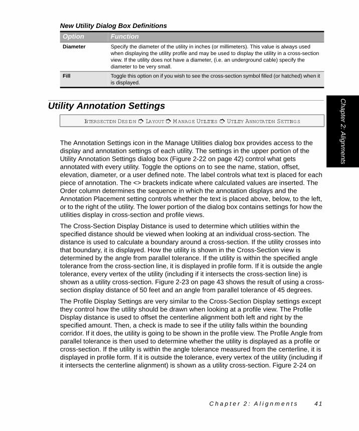
Utility Annotation Settings
The Annotation Settings icon in the Manage Utilities dialog box provides access to the display and annotation settings of each utility. The settings in the upper portion of the Utility Annotation Settings dialog box (Figure 2-22 on page 42) control what gets annotated with every utility. Toggle the options on to see the name, station, offset, elevation, diameter, or a user defined note. The label controls what text is placed for each piece of annotation. The <> brackets indicate where calculated values are inserted. The Order column determines the sequence in which the annotation displays and the Annotation Placement setting controls whether the text is placed above, below, to the left, or to the right of the utility. The lower portion of the dialog box contains settings for how the utilities display in cross-section and profile views.
The Cross-Section Display Distance is used to determine which utilities within the specified distance should be viewed when looking at an individual cross-section. The distance is used to calculate a boundary around a cross-section. If the utility crosses into that boundary, it is displayed. How the utility is shown in the Cross-Section view is determined by the angle from parallel tolerance. If the utility is within the specified angle tolerance from the cross-section line, it is displayed in profile form. If it is outside the angle tolerance, every vertex of the utility (including if it intersects the cross-section line) is shown as a utility cross-section. Figure 2-23 on page 43 shows the result of using a cross-section display distance of 50 feet and an angle from parallel tolerance of 45 degrees.
The Profile Display Settings are very similar to the Cross-Section Display settings except they control how the utility should be drawn when looking at a profile view. The Profile Display distance is used to offset the centerline alignment both left and right by the specified amount. Then, a check is made to see if the utility falls within the bounding corridor. If it does, the utility is going to be shown in the profile view. The Profile Angle from parallel tolerance is then used to determine whether the utility is displayed as a profile or cross-section. If the utility is within the angle tolerance measured from the centerline, it is displayed in profile form. If it is outside the tolerance, every vertex of the utility (including if it intersects the centerline alignment) is shown as a utility cross-section. Figure 2-24 on
Diameter Specify the diameter of the utility in inches (or millimeters). This value is always used when displaying the utility profile and may be used to display the utility in a cross-section view. If the utility does not have a diameter, (i.e. an underground cable) specify the diameter to be very small.
Fill Toggle this option on if you wish to see the cross-section symbol filled (or hatched) when it is displayed.
INTERSECTION DESIGN # LAYOUT # MANAGE UTILITIES # UTILITY ANNOTATION SETTINGS
New Utility Dialog Box DefinitionsOption Function
C h a p t e r 2 : A l i g n m e n t s 4 1

page 44 shows the result of using a Profile Display Distance of 150 feet and an Angle from parallel tolerance of 60 degrees.
Figure 2-22 Utility Annotation Settings Dialog Box
Utility Annotation Settings Dialog Box DefinitionsOption FunctionUtility This drop list contains every utility that is defined in the Manage Utilities dialog box. Each
utility has its own settings for the display and annotation of when it is viewed.
Annotation The toggles for each item control whether or not that item should be annotated when the utility is viewed. The label lets you specify what text appears with the utility and the order controls the sequence in which the labels are placed. Items that can be annotated include the name, station, offset, elevation, diameter, or a user-defined note.
Annotation Placement
This option controls where the Annotation items display when the utility is viewed. Choose to place the annotation above, below, to the left, or to the right of the utility.
Cross-Section Display Distance
This distance defines the boundary to search for the utility to see if it should be displayed in a cross-section. The distance is used to offset the cross-section line and form a boundary around the cross-section. If the utility falls inside the boundary, it is seen in the cross-section view.
Cross-Section Angle from parallel tolerance
This angle tolerance (measured in degrees) is used to determine whether a utility is seen as a profile in a cross-section view. If the closest utility leg to the cross-section is within the tolerance, it is displayed in profile form.
Profile Display Distance
This distance defines the boundary to search for the utility to see if it should be displayed in a profile view. The distance is used to offset the centerline alignment and form a boundary around it. If the utility falls inside the boundary, it is seen in the profile view.
4 2 W a t e r S u r f a c e P r o f i l i n g

Chapter 2: Alignm
ents
Profile Angle from parallel tolerance
This angle tolerance (measured in degrees) is used to determine whether a utility segment (leg) is seen as a profile in a profile view. If a utility leg is within this tolerance, it is displayed in profile form.
Figure 2-23 Utilities Displayed In A Water Surface Profiling Cross-Section View
Utility Annotation Settings Dialog Box DefinitionsOption Function
C h a p t e r 2 : A l i g n m e n t s 4 3

View Alignment Graphics
KEY-IN COMMAND: wpalview
ICON:
Use the View Alignment Graphics command to display the alignment graphics placed in CAD.
If numeric changes were made to the alignment while the Plan Graphic was not loaded, Water Surface Profiling displays the Synchronize Graphics and Data dialog box (Figure 2-25 on page 45) asking which information is correct – the graphic representation or numeric.
See Synchronize Graphics and Data on page 45.
Figure 2-24 Utilities Displayed In A Water Surface Profiling Profile View
WATER SURFACE PROFILING # ALIGNMENTS # VIEW ALIGNMENT GRAPHICS
4 4 W a t e r S u r f a c e P r o f i l i n g

Chapter 2: Alignm
ents
Synchronize Graphics and Data
KEY-IN COMMAND: wpalsync
This command can be accessed to verify that the graphic representation of a Water Surface Profiling object matches the numeric information. If differences exist, you determine whether the graphic or numeric information is correct. Selecting the Update Graphics button writes the numeric information to the graphic. Selecting the Update Data button writes the graphic information to the numeric.
The dialog box below automatically displays if Water Surface Profiling finds any differences when accessing a data set and corresponding graphic.
" This option is unavailable until the plan CAD graphic is loaded.
WATER SURFACE PROFILING # ALIGNMENTS # SYNCHRONIZE GRAPHICS & DATA
Figure 2-25 Synchronize Graphics and Data Dialog Box
Synchronize Graphics and Data Dialog Box DefinitionsOption FunctionUpdate Graphics Click on this button to update the alignment graphics in CAD from the numeric data.
Update Data After graphically modifying a Water Surface Profiling alignment, use this command to update the numeric data based on the graphic changes.
Details Click on this button to display the Compare Alignments dialog box. When there is a graphic and numeric difference, this dialog box displays the Alignment Inverse for the data representation and graphic representation to assist you in determining which information should be used to update the other. The two list boxes stay in sync with one another as you highlight specific items in either list.
C h a p t e r 2 : A l i g n m e n t s 4 5

4 6 W a t e r S u r f a c e P r o f i l i n g

C H A P T E R
3
C R O S S -S E C T I O N SAll of the cross-section data can be entered using the Cross-Sections menu. You can directly enter the cross-section data in the dialog box or extract the cross-section from a surface model (DTM). There is also an option to import cross-sectional data from an ASCII file. This is also where you can export cross-sectional data to HEC-2 if needed.
In this chapter:
Cross-Sections Concepts . . . . . . . . . . . . . . . . . . . . . . 48
Edit Cross-Section Data . . . . . . . . . . . . . . . . . . . . . . . 53
Extract Cross-Sections . . . . . . . . . . . . . . . . . . . . . . . . 64
Annotate Cross-Sections . . . . . . . . . . . . . . . . . . . . . . 68
Import Cross-Sections. . . . . . . . . . . . . . . . . . . . . . . . . 70
Export Cross-Sections . . . . . . . . . . . . . . . . . . . . . . . . 76
Create User Formats. . . . . . . . . . . . . . . . . . . . . . . . . . 77
View Cross-Section Graphics . . . . . . . . . . . . . . . . . . . 79
Cross-Section Settings . . . . . . . . . . . . . . . . . . . . . . . . 79
Synchronize Graphics and Data . . . . . . . . . . . . . . . . . 82
C h a p t e r 3 : C r o s s - S e c t i o n s 4 7

Cross-Sections ConceptsThe commands found in the Cross-Sections menu allow you to input, edit, and translate the cross-sectional data. Enter and edit the data directly with the Edit Cross-Sections routine, or bring the cross-section data into Water Surface Profiling from outside sources using the Extract Cross-Sections or the Import Cross-Sections routines. The data can be translated in the WSPRO or HEC-2 formats among others.
$ Cross-sections must be placed at the PI locations of the stream alignment. If the cross-sections are omitted from the stream alignment PI’s, the reach lengths may not be calculated correctly when the data is exported to HEC-RAS.
Cross-Section TypesThere are three cross-section types that are supported in Water Surface Profiling. These three types are Normal, Skewed, and Fixed. Normal cross-sections are cross-sections perpendicular to the stream alignment. Fixed cross-sections are briefly described in Chapter 2 (Alignments on page 15). Fixed cross-sections follow the cross-section alignments. Skewed cross-sections are described in Skewed Cross-Sections (below).
Skewed Cross-SectionsSkewed cross-sections are available for cross-section locations that require an angle other than perpendicular to the stream alignment (0 degrees).
Determine the angle at which the cross-sections are skewed by one of five methods:
! Left-Hand Forward (LHF)
! Right-Hand Forward (RHF)
! Deflection Left (DL)
! Deflection Right (DR)
! Azimuth (AZ): Based upon 360 degrees
Selecting LHF allows angles to be entered from -90 degrees to 90 degrees to be read from the second and third quadrants. Selecting RHF allows angles to be entered -90 degrees to 90 degrees to be read from the first and fourth quadrants. Figure 3-1 on page 49 illustrates the LHF and RHF methods and quadrants. Selecting Deflection Left allows angles to be entered from 0 degrees to 180 degrees to be read from the second and third quadrants. Selecting Deflection Right allows angles to be entered from 0 degrees to 180 degrees to be read from the first and fourth quadrants. If none of these four are specified,
4 8 W a t e r S u r f a c e P r o f i l i n g

Chapter 3: C
ross-Sections
use the Azimuth method and enter an angle between 0 degrees and 360 degrees as shown in Figure 3-3 (below).
The Right-Hand Forward convention can be explained by imagining that the gray line (the light solid line) in Figure 3-4 on page 50 represents a person’s arms extending out from their sides, 90 degrees, looking downstream along the alignment. The black line (the heavy solid line) in each figure represents the person’s arms if they rotate their body (keeping their arms straight), to the angle specified. In the first figure, the person’s right
Figure 3-1 LHF And RHF For Measuring Skew Angle
Figure 3-2 DL And DR For Measuring Skew Angles
Figure 3-3 360 Degree Method For Measuring Skew Angle
C h a p t e r 3 : C r o s s - S e c t i o n s 4 9

arm moved forward 20 degrees of rotation. In the second figure, the left arm moved forward 20 degrees (LHF) which causes the right arm to move backwards 20 degrees, or -20 degrees forward (RHF).
Cross-Section StationingUnlike roadway cross-sections, the cross-sections in Water Surface Profiling do not use Offsets and Elevations to describe the cross-section. Water Surface Profiling uses stations and elevations. You define a station at center value in Cross-Section Settings that represents the station on the cross-section where it crosses the stream centerline. Another important difference is that the stationing along the cross-section runs left to right as you look downstream, not in the direction of the stream stationing. This applies to all of the cross-section types. See Figure 3-5 (below).
Figure 3-4 Explanation Of RHF Convention
Figure 3-5 Cross-Section Stationing Example
5 0 W a t e r S u r f a c e P r o f i l i n g
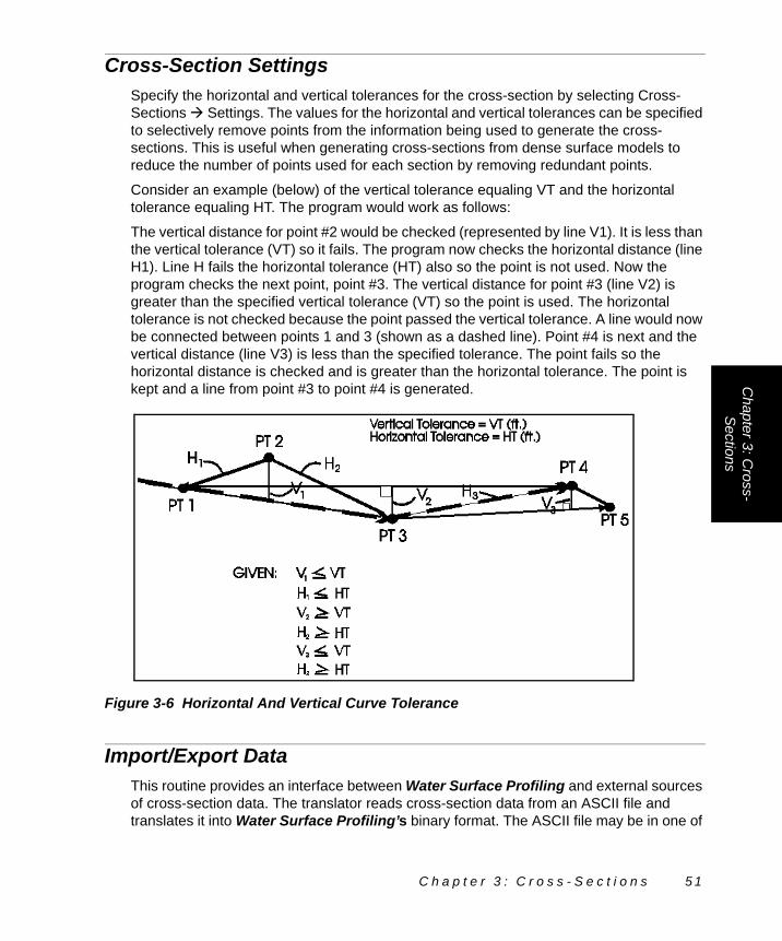
Chapter 3: C
ross-Sections
Cross-Section SettingsSpecify the horizontal and vertical tolerances for the cross-section by selecting Cross-Sections ! Settings. The values for the horizontal and vertical tolerances can be specified to selectively remove points from the information being used to generate the cross-sections. This is useful when generating cross-sections from dense surface models to reduce the number of points used for each section by removing redundant points.
Consider an example (below) of the vertical tolerance equaling VT and the horizontal tolerance equaling HT. The program would work as follows:
The vertical distance for point #2 would be checked (represented by line V1). It is less than the vertical tolerance (VT) so it fails. The program now checks the horizontal distance (line H1). Line H fails the horizontal tolerance (HT) also so the point is not used. Now the program checks the next point, point #3. The vertical distance for point #3 (line V2) is greater than the specified vertical tolerance (VT) so the point is used. The horizontal tolerance is not checked because the point passed the vertical tolerance. A line would now be connected between points 1 and 3 (shown as a dashed line). Point #4 is next and the vertical distance (line V3) is less than the specified tolerance. The point fails so the horizontal distance is checked and is greater than the horizontal tolerance. The point is kept and a line from point #3 to point #4 is generated.
Import/Export DataThis routine provides an interface between Water Surface Profiling and external sources of cross-section data. The translator reads cross-section data from an ASCII file and translates it into Water Surface Profiling’s binary format. The ASCII file may be in one of
Figure 3-6 Horizontal And Vertical Curve Tolerance
C h a p t e r 3 : C r o s s - S e c t i o n s 5 1

Water Surface Profiling’s pre-defined formats, or define a custom format for the data. Water Surface Profiling can also translate from Water Surface Profiling binary to ASCII formats. Keep in mind that you can export HEC-2 and WSPRO formats as well.
The data in the ASCII file can be in coordinate or station-offset format, but the data must be taken along cross-section lines. Also, if the ASCII file contains data in station-offset format, the stations must be listed in order along the sub-project. If the data is in coordinate format, the stations may be out of order, but the horizontal alignment must be entered before translating.
Before translating, remove any extraneous lines from the ASCII file: title blocks, comments (unless they are part of a descriptor field), and any blank lines, whether they are at the beginning, middle or end of the file.
When importing a coordinate ASCII file, you can toggle on the station tolerance option found in the transfer settings. Specify the station tolerance and station interval. This allows you to force the points in the ASCII file to fall on exact station values within the tolerance specified. When the option is toggled on, the station values along the centerline alignment are calculated for the points. The calculated stations in the file are compared to the interval stations along the centerline alignment. The difference between their actual station value and the stations at interval will then be compared to the station tolerance. If the point is inside the tolerance the shot is assigned to the interval station. If a shot is outside the tolerance it is added to a running list and displayed at the end of the command. When all other shots are given an interval station, the Assign Points to Station dialog box (Figure 3-23 on page 75) is displayed. This allows you to decide what to do with all shots outside of the station tolerance. Points can be discarded or assigned to existing or new station values. To assign a point to a station value, highlighting the rows that belong to the same station and then use the Assign Station button to enter the station at which the shots belong. As changes are made (i.e. a group of shots are assigned a station) the list of points in the Assign Points to Station dialog box are updated by removing the shots that were in the highlighted group. If points are not assigned to a station value and the Assign Points to Station dialog box is closed, the shots are discarded.
For example, in the Transfer Settings – Import Tab, set the station tolerance to 0.5 and the station interval to be 10. If the data importing calculated a station of 99+99.89 from the coordinates because of precision, Water Surface Profiling would automatically adjust that station to be 100+00 since the station tolerance of 0.11 is less than 0.5.
If the ASCII file contains sideshots that are not to be translated, group these shots at the end of each cross-section and put an XX in the descriptor field of the last point that is translated for that cross-section. Water Surface Profiling ignores all points including and after the one marked with the XX until it reaches the points on the next cross-section.
If there is already cross-section data for the surface you are translating, Water Surface Profiling must know what to do if it encounters a station in the ASCII file that matches a station already in the sub-project. It can either overwrite the old data at that station or add the new shots to the shots already there (append). If a window displays asking if the old data is to be overwritten, indicate the action to be taken.
5 2 W a t e r S u r f a c e P r o f i l i n g

Chapter 3: C
ross-Sections
" Water Surface Profiling first counts the points in the ASCII file, then translates the data from the ASCII file into the Water Surface Profiling cross-section files.
Edit Cross-Section Data
KEY-IN COMMAND: wpxsdata
ICON:
When the Edit Data command is selected from Water Surface Profiling’s Cross-Sections menu, Water Surface Profiling opens the Edit Cross-Section Data dialog box (Figure 3-7 on page 54). The upper list box contains a listing of all the cross-sections along the stream in the sub-project. The lower list box shows stations and elevations along the highlighted cross-section. If cross-section data has not been entered, the dialog box shows no cross-sections.
If cross-section alignments have been defined, the cross-section stations display in the Stream Station listing with a status of F for fixed. These cross-sections cannot be deleted from the listing. They must be deleted from the Alignment Manager in the Alignment menu.
If the cross-section has been interpolated from existing cross-section geometry, an I displays in the Stream Station listing.
Unless the Import or Extract Cross-Sections commands have been used to bring data into Water Surface Profiling, the Edit command is used to enter and edit data for the ground surface.
Added cross-sections are automatically sorted by their station values. Multiple stations may be added at one time by using the Build List option.
" To enter cross-section data graphically, the cross-sections CAD graphic must be loaded. If not, use the View Cross-Section Graphics command found in the Cross-Sections menu. A vertical line representing the centerline and a station label indicating the station being viewed display. From this point, the cross-section can be drawn. Use lines or polylines/line strings to represent each surface.
" Coordinates: The X-coordinate in the cross-section CAD graphic corresponds to the stream centerline offset. The Y-coordinate is the elevation if the vertical stretch factor is set to one. Otherwise, the Y-coordinate is the elevation multiplied by the vertical stretch factor. See Cross-Section Settings on page 51 for details on the vertical stretch factor.
WATER SURFACE PROFILING # CROSS-SECTIONS # EDIT DATA
C h a p t e r 3 : C r o s s - S e c t i o n s 5 3

Unlike most other routines in Water Surface Profiling, the cross-section routine does not save the CAD graphic it uses. The CAD graphic here is merely a graphic environment for the cross-section work. Once editing of a section is complete, Water Surface Profiling saves the data in its own files and discards the CAD graphic. Annotation or other extraneous information is lost.
Figure 3-7 Edit Cross-Section/Display Stations, Preview and Shots Data Dialog Box
Figure 3-8 Edit Cross-Section Data/Display Stations and Preview Dialog Box
5 4 W a t e r S u r f a c e P r o f i l i n g

Chapter 3: C
ross-Sections
Figure 3-9 Edit Cross-Section Data/Display Stations Dialog Box
Edit Cross-Section Data/Display Stations Dialog Box DefinitionsOption Icon Function# This column displays a number assigned to each cross-section listed.
Station This column in the upper portion of the dialog box displays the station value of a cross-section. Station values are displayed according to system settings.
Skew This column displays the skew angle value for each station location. The skew angle value is based on 0 degrees being at a right angle to the alignment and rotation counterclockwise up to 360 degrees.
Fixed This column displays an F if the cross-section is a fixed cross-section. A fixed cross-section alignment is defined in the section named Manage Alignments on page 30. If the cross-section is interpolated from existing cross-section geometry, an I displays in this column.
New Stream Station
Click on this icon to add a new stream station to the cross-section listing. See New Stream Station on page 57 for additional information.
Modify Stream Station
Click on this icon to modify the stream station information.
Copy Stream Station
Click on this icon to copy stream station information from one station to another.
Delete Stream Station
Click on this icon to delete the highlighted stream station from the project.
Surface CAD Settings
Click on this icon to assign CAD properties to the graphic.
Print Cross Section Data
Use this command to print cross section data.
Interpolate This button allows you to interpolate cross-sections between known cross-sections. You can interpolate a cross-section at a specified stream station or multiple cross-sections at a specified interval.
Shot at Station This Station listing displays the station along the cross-section alignment for the particular cross-section shot. Keep in mind that the Station At Center setting dictates the stationing on the cross-section.
C h a p t e r 3 : C r o s s - S e c t i o n s 5 5

Station The Station column in the bottom portion of the dialog box denotes the station along the cross-section at which the shot is located.
Elevation The Elevation column indicates the elevation of the particular breakpoint in question.
Slope This column displays the slope from the previous shot to the current shot. The slope is displayed in % Slope, H/V, V/H, or Unit/Unit depending on what slope type is selected.
IH This column indicates the height of the instrument used to collect information for that particular cross-section. The value that is displayed is the elevation of the instrument, not the instrument’s relative distance above ground.
RR This column displays the Rod Reading (RR) of the specified shot depending on the display format.
OB This columns displays an L if the shot is the Left Overbank, an R if the shot is the Right Overbank and C if the shot is the center of the channel.
PT Code This column displays the PT Code value for the particular cross-section shot.
New Shot Click on the New Shot icon to add a cross-section shot by specifying offset and elevation by offset, rod reading, instrument height and elevation, or by percent slope and slope distance.
For more information, see New Shot on page 59.
Modify Shot Click on the Modify Shot icon to make changes to the offset, rod reading, instrument height, elevation, percent slope, or slope distance for the highlighted cross-section shot. This is the same as New Shot, except that you highlight a cross-section shot first.
For more information, see New Shot on page 59.
Delete Shot Click on the Delete Shot icon to remove the highlighted shot from the current surface of the current station. More than one shot can be highlighted by pressing the Shift and Ctrl keys while selecting the shots to be deleted.
Slope Type This drop list changes the display of the slope between breakpoints to show % Slope, H/V, V/H, or Unit/Unit.
View Cross-Section Graphic
This option loads the cross-section CAD graphic to display the highlighted station’s cross-section data.
Query Cross-Section
This displays the query cross-section window to view individual stations and query breakpoint information. For more information, see Query Cross-Section on page 63.
Display Stations This option displays the Edit Cross-Section Data dialog box (Figure 3-9 on page 55) showing only the station list.
Display Stations and Preview
This option displays the Edit Cross-Section Data dialog box (Figure 3-8 on page 54), showing the station list and the preview image of the highlighted cross-section.
Display Stations, Preview and Shots
This option displays the station list, preview image and shot information in the Edit Cross-Section Data dialog box (Figure 3-7 on page 54).
Edit Cross-Section Data/Display Stations Dialog Box DefinitionsOption Icon Function
5 6 W a t e r S u r f a c e P r o f i l i n g

Chapter 3: C
ross-Sections
New Stream Station
To add a new stream station to the cross-section listing, click on the New Stream Station icon in the Edit Cross-Section Data dialog box (Figure 3-7 on page 54).
The New Stream Station dialog box (Figure 3-10 on page 57) displays. A new station value may be typed or selected from CAD using the PIC button.
A cross-section may be skewed from the normal perpendicular by setting a skew angle other than 0.
See Skewed Cross-Sections on page 48 for further explanation.
See Edit Cross-Section Data on page 53.
WATER SURFACE PROFILING # CROSS-SECTIONS # EDIT DATA # NEW STREAM STATION
Figure 3-10 New Stream Station Dialog Box
New Stream Station Dialog Box DefinitionsOption Icon FunctionStation Enter the stream station of the new cross-section to be added to the Edit Cross-Section
Data dialog box.
PIC This is used to pick a graphic point for a station when the method is set to Station.
For more information, see Pick in CAD (PIC) Button in the Getting Started manual.
Skew Enter the skew angle for the new cross-section to be added to the Edit Cross-Section Data dialog box in this field. The default is 0 degrees or perpendicular to the alignment.
For more information, see Skewed Cross-Sections on page 48.
LHF Set the drop list to the LHF option to use the Left-Hand Forward method of skew angle specification. By selecting LHF, angles can be entered from -90 degrees to 90 degrees to be read from the second and third quadrants.
RHF Set the drop list to the RHF option to use the Right-Hand Forward method of skew angle specification. By selecting RHF, angles can be entered from -90 degrees to 90 degrees to be read from the first and fourth quadrants.
DR Setting the drop list to DR allows skew angles to be entered as an amount deflected to the right from the forward tangent direction.
DL Setting the drop list to DL allows skew angles to be entered as an amount deflected to the left from the forward tangent direction.
C h a p t e r 3 : C r o s s - S e c t i o n s 5 7

Build Station List
The Build List command allows you to choose a new station interval and the range for the cross-sections to be generated. You can specify the station intervals along a tangent and along a horizontal curve. You can specify if you want a skew angle applied to all of the cross-sections. You can also automatically mark the cross-sections for extraction (when using the Extract Cross-Section command) and delete any cross-sections that already exist within the station range specified.
AZ When set to Azimuth, the skew angle is entered as a value from 0 to 360 degrees clockwise.
Build List Click on the Build List button to add stations by range and interval.
For more information, see Build Station List on page 58.
WATER SURFACE PROFILING # CROSS-SECTIONS # EDIT DATA # NEW STREAM STATION # BUILD LIST
Figure 3-11 Build Station List Dialog Box
Build Station List Dialog Box DefinitionsOption Icon FunctionStation Range This option specifies the linear distance at which the cross-section
information is generated.
Begin Station This specifies the station for the cross-sections to begin.
End Station This allows you to enter the station for the cross-sections to end.
Pick in CAD Use this button to select objects or points in CAD to retrieve information from the graphic.
New Stream Station Dialog Box DefinitionsOption Icon Function
5 8 W a t e r S u r f a c e P r o f i l i n g

Chapter 3: C
ross-Sections
New Shot
To add a shot, click on the New Shot button in the Edit Cross-Section Data dialog box (Figure 3-7 on page 54). There are three different methods that can be used to add a new shot onto a cross-section. Depending on the type of surface, there are different combinations of the three methods available. The three methods are: Station/Elevation, Instrument Height/Rod Reading, and Slope/Distance. Figure 3-12 (below), Figure 3-13 on page 61 and Figure 3-14 on page 62 show how to use the three different methods.
Stationing Interval
Toggle on this option to set the station interval along tangent sections of the horizontal alignment. Enter the desired station interval in the associated edit field.
Curve Stationing Interval
Toggle on this option to use a different station interval through horizontal curves. Enter the desired station interval in the associated edit field.
Curve Stations Toggle on this option to include PC and PT stations in between the start and end station range values.
Skew Angle Specify a value for an angle of the cross-section; otherwise, cross-sections are perpendicular to the alignment.
Mark Stations For Extraction
Toggle on this option to automatically mark all stations for extraction.
Delete Existing Stations
Toggling on this option deletes all the stations in between the start and end station that are affected by the change in the station interval.
WATER SURFACE PROFILING # CROSS-SECTIONS # EDIT DATA # NEW SHOT
Figure 3-12 New Shot Station/Elevation Dialog Box
Build Station List Dialog Box DefinitionsOption Icon Function
C h a p t e r 3 : C r o s s - S e c t i o n s 5 9

If the method of Instrument Height/Rod Reading is selected to add shots, the New Shot IH/RR Dialog Box dialog box (below) displays.
New Shot Station/Elevation Dialog Box DefinitionsOption Icon FunctionMethod This displays the different methods with which you can enter cross-section shots.
The available options are Station/Elevation, Instrument Height/Rod Reading, and Slope/Distance.
Pick in CAD Use this button to select objects or points in CAD to retrieve information from the graphic.
PT Code This option allows you to specify a point code for reference.
Library Clicking on this icon displays the PT Code Library. You can also click on the PT Code Library icon to add, modify, and delete PT codes from the library.
Station This option allows you to specify the station along the cross-section where you want the shot added.
Elevation This option allows you to specify the elevation of the shot being added.
Uncontrolled When this radio button is turned on, this is the default setting for all shots. This specifies that the shot is a normal cross-section shot.
Left Overbank When this radio button is turned on, this specifies that this shot is the left overbank. This specifies that this is the leftmost shot of the channel.
Right Overbank
When this radio button is turned on, this specifies that this shot is the right overbank. This specifies that this is the rightmost shot of the channel.
Figure 3-13 New Shot IH/RR Dialog Box
New Shot IH/RR Dialog Box DefinitionsOption Icon FunctionMethod This displays the different methods with which you can enter cross-section
shots with. The available options are Station/Elevation, Instrument Height/Rod Reading and Slope Distance.
6 0 W a t e r S u r f a c e P r o f i l i n g

Chapter 3: C
ross-Sections
The final method of entering shots is through slope and distance. This option displays the New Shot Slope/Distance dialog box (below).
Pick in CAD Use this icon to select objects or points in CAD to retrieve information from the graphic.
PT Code This option allows you to specify a point code for reference.
Library Clicking on this icon displays the PT Code Library. You can also click on the PT Code Library icon to add, modify and delete the PT codes from the library.
Station This option allows you to specify the station along the cross-section where you want the shot added.
Elevation This option allows you to specify the elevation of the shot being added.
IH Specify the instrument height in this edit field. This is the elevation of the instrument, not the instrument’s relative distance above ground.
RR Specify the rod reading in this edit field.
Uncontrolled When this radio button is on, this is the default setting for all shots. This specifies that the shot is a normal cross-section shot.
Left Overbank When this radio button is on, this specifies that this shot is the left overbank. This specifies that this is the leftmost shot of the channel.
Right Overbank When this radio button is on, this specifies that this shot is the right overbank. This specifies that this is the rightmost shot of the channel.
Figure 3-14 New Shot Slope/Distance Dialog Box
New Shot IH/RR Dialog Box DefinitionsOption Icon Function
C h a p t e r 3 : C r o s s - S e c t i o n s 6 1

New Shot Slope/Distance Dialog Box DefinitionsOption Icon FunctionMethod This displays the different methods with which you can enter cross-section
shots. The available options are Station/Elevation, Instrument Height/Rod Reading and Slope Distance.
Pick in CAD Use this button to select objects or points in CAD to retrieve information from the graphic.
PT Code This option allows you to specify a PT Code for reference.
Library Clicking on this icon displays the PT Code Library. You can also click on the PT Code Library icon to add, modify and delete PT codes from the library.
Slope Slope is the absolute slope from the center or 0 offset for the shot being added. Choose one of four types of slope: % Slope, H/V, V/H, or Unit/Unit.
Distance Specify the distance of the point being added from the center or 0 offset for the shot being added in this edit field. Set the drop list to either horizontal or slope distance entry.
Uncontrolled When this radio button is on, this is the default setting for all shots. This specifies that the shot is a normal cross-section shot.
Left Overbank When this radio button is on, this specifies that this shot is the left overbank. This specifies that this is the leftmost shot of the channel.
Right Overbank When this radio button is on, this specifies that this shot is the right overbank. This specifies that this is the rightmost shot of the channel.
6 2 W a t e r S u r f a c e P r o f i l i n g

Chapter 3: C
ross-Sections
Query Cross-Section
ICON:
The Query Cross-Section command allows you to display the cross-sections in the Query Cross-Section dialog box (below).
This dialog box shows the cross-section graphic and shot information for each breakpoint on the cross-section. The arrow head moves between shots on a cross-section by using the Next Shot and Previous Shot commands and displays the offset, elevation, and PT Code information for each. The slope between the current shot and the previous shot is also displayed.
Any utilities defined in the project also display in the cross-section window. By changing the surface list to Utilities, you may use the Next and Previous Shot commands to display the utility name, offset, elevation, and station.
The cross-section graphic may be panned to the left, right, up, or down using the scroll bars. The Scale View command controls the zoom factor to display more or less of the cross-section graphic in the display window.
WATER SURFACE PROFILING # CROSS-SECTIONS # EDIT DATA # QUERY CROSS-SECTION
Figure 3-15 Query Cross-Section Dialog Box
C h a p t e r 3 : C r o s s - S e c t i o n s 6 3

Any cross-section may be viewed by using the Goto Station command or by using the Previous and Next Cross-Section options.
Extract Cross-Sections
KEY-IN COMMAND: wpxsfsm
When the Extract from Surface Model command is selected from Water Surface Profiling’s Cross-Sections pull-down menu, the Extract Cross-Sections dialog box
Query Cross-Section Dialog Box DefinitionsOption Icon FunctionHorizontal and Vertical Scroll Bars
These allow you to pan the cross-section to the left, right, up, and down.
Next/Previous Shot
The query arrow may be moved to the left or right on the current surface to display the shot information. This displays the offset, elevation, slope, and PT code for the shot.
Previous Cross-Section
Use this option to display the cross-section that occurs before the current cross-section. This is disabled if you are viewing the first cross-section.
Next Cross-Section
Use this option to display the cross-section that occurs after the current cross-section. This is disabled if you are viewing the last cross-section.
Goto Station Click on this to display the Goto Station dialog box. Highlight the station to view. The display window now shows that cross-section information. This dialog box can remain open to allow you to scroll through all cross-sections.
Scale View This provides access to the Scale View command to set the Horizontal and Vertical scales at which to display the cross-section graphic. Use this command to set the zoom factor for the display.
PT Code This displays the PT Code of the shot that the query arrow is on.
Station This displays the cross-section station value of the shot that the query arrow is on.
Elevation This displays the elevation value of the shot that the query arrow is on.
Slope This displays the slope of the line between the current shot and previous shot.
Slope Type This drop list allows you to change the slope display between % Slope, H/V, V/H, or Unit/Unit.
WATER SURFACE PROFILING # CROSS-SECTIONS # EXTRACT FROM SURFACE M ODEL
6 4 W a t e r S u r f a c e P r o f i l i n g

Chapter 3: C
ross-Sections
(Figure 3-16 on page 66) displays. If the sub-project has no cross-sections yet, the program opens the Build Station List dialog box (Figure 3-11 on page 58), and allows you to set the desired station range and station interval.
This routine allows cross-sections to be created from a surface model created previously with the Eagle Point Surface Modeling product. The program routes the stream centerline alignment through the model, and at requested stations, slices the model with vertical planes perpendicular to the alignment for normal cross-sections. Wherever a plane intersects a surface model triangle line, a cross-section shot is generated. In the case of fixed cross-sections, a cross-section shot is generated everywhere the cross-section line crosses a surface model triangle and at the vertex points of the cross-section alignment.
Once the stations are marked appropriately, click on OK to initiate the cross-section generation process.
After processing, Water Surface Profiling may display an error dialog box. This indicates stations where it was not able to generate data all the way out to the corridor edges, and stations where it was not able to find any data at all.
" Enter a stream centerline alignment before generating cross-sections from a surface model.
" Instead of specifying a surface model, choose the user-defined option in the Surface Model drop list to specify a drawing/design file that contains three-dimensional information. Water Surface Profiling extracts shot data from the three-dimensional elements it intersects.
C h a p t e r 3 : C r o s s - S e c t i o n s 6 5

" The Mark button places an X in the Mark for Extraction column. The Unmark button removes the X in the Mark for Extraction column. Multiple cross-section stations can be highlighted by using the Shift or Ctrl keys in conjunction with mouse button clicks.
Figure 3-16 Extract Cross-Sections Dialog Box
Extract Cross-Sections Dialog Box DefinitionsOption Icon FunctionOriginal Ground Surface Model
This drop list contains the list of surface models created for this project. Set the list to the name of the model from which you want to extract cross-sections. You can also click on the Globe icon to access models created in other Eagle Point projects. After selecting another project’s SM file, the available models can be selected for use. If the Surface Model drop list is set to User-Defined, the program extracts cross-sections, from three-dimensional objects. By default, the program uses the sub-project’s plan CAD graphic. If you want to use a different CAD graphic, click on the Globe icon to select a different CAD graphic file.
For more information, see Global Surface Models on page 68.
Global Surface Model
Click on this icon to access surface models created in other Eagle Point projects or to establish a CAD graphic name from which to extract cross-section data.
Corridor Edge Left
This defines how wide the cross-sections are to be. Enter the offsets for the right corridor edge in the field. Enter a negative value for an offset left of the stream centerline or a positive value for an offset right of the stream centerline.
Corridor Edge Right
This defines how wide the cross-sections are to be. Enter the offsets for the left corridor edge in the field. Enter a negative value for an offset left of the stream centerline or a positive value for an offset right of the stream centerline.
6 6 W a t e r S u r f a c e P r o f i l i n g

Chapter 3: C
ross-Sections
User-Defined Corridor
Toggle this option on to select a two polylines/linestrings to be used to define the corridor edges. After clicking on OK, you are prompted to select the bounding objects.
Stationing This column displays the list of stations that was generated from the Build Station List dialog box (Figure 3-11 on page 58) or entered using the New Station option.
Skew Angle This column indicates the skew angle for each cross-section. The default value is 0 degrees.
Fixed This column indicates whether the station value is for a fixed cross-section.
Extract The stations marked with an X are the station locations at which Water Surface Profiling generates cross-section information.
New Stream Station
This icon places and sorts a station value to be extracted in the currently defined list. Cross-sections cannot be added to the list if the station value is past the ending station of the stream centerline alignment.
For more information, see New Stream Station on page 57.
Modify Stream Station
Change the station and skew angle values for the highlighted station. Modify the type of skew angle and whether or not to extract it. You cannot modify the station value for a fixed cross-section. Fixed cross-sections must be modified in the Manage Alignments dialog box.
See Manage Alignments on page 30. The functionality for this is the same as New Stream Station except that you highlight an existing station.
For more information, see New Stream Station on page 57.
Delete Stream Station
Click on this icon to remove the highlighted cross-section from the station list. More than one station may be highlighted using the Shift or Ctrl keys in conjunction with mouse button clicks. Fixed cross-sections cannot be deleted. They can only be deleted from the Manage Alignments dialog box.
See Manage Alignments on page 30.
Mark If Water Surface Profiling is to regenerate data for sections already there (if the surface model has changed, for instance), use the Mark command to mark the desired cross-sections or double-click on a station to mark and unmark it. You may mark more than one station at a time by highlighting the appropriate stations in the list.
Unmark If you do not want Water Surface Profiling to extract data for a given station, use the Unmark command to unmark stations for extraction. You may unmark more than one station at a time by highlighting the appropriate stations in the list.
Build List Use this command to build a list of stations to extract.
For more information, see Build Station List on page 58.
Settings Click on this button to modify the horizontal and vertical tolerances for cross-section data to be used.
Extract Cross-Sections Dialog Box DefinitionsOption Icon Function
C h a p t e r 3 : C r o s s - S e c t i o n s 6 7
Global Surface Models
The Global Surface Models command, accessed by clicking on the Globe Icon on the Extract Cross-Sections dialog box (Figure 3-16 on page 66), is used to access surface models created in other Eagle Point projects, or to establish a CAD graphic name from which to extract cross-section data. When selected, the Global Surface Model command opens a file selection window, filtering for AutoCAD/BricsCad drawings (*.DWG), MicroStation design files (*.DGN) or Eagle Point surface models (*.SM). You may select a CAD graphic that contains three-dimensional information from which to extract cross-sectional data. If the Eagle Point surface models filter (*.SM) is used, you may select a model that has been created in another Eagle Point project. The SM file for a project is located in the project’s data file location and it contains the listing of the surface models created for that project. After selecting the SM file for a project, another dialog box displays with the model names for that project. After choosing one, the Select dialog box is closed and the name of the selected CAD graphic or surface model is displayed in the drop list, corresponding to the Global Surface Model button selected.
Annotate Cross-Sections
KEY-IN COMMAND: wpxsann
This command gives you the ability to annotate the cross-section number and stream station next to the cross-section line drawn in the Plan view. You can place the cross-section number, cross-section station, or both next to the cross-section alignment. The CAD settings for the text can be set in addition to plotting the cross-section lines in the Plan drawing. Figure 3-17 on page 69 illustrates how the text is placed next to the cross-
WATER SURFACE PROFILING # CROSS-SECTIONS #EXTRACT FROM SURFACE MODEL # GLOBAL SURFACE M ODELS
WATER SURFACE PROFILING # CROSS-SECTIONS #ANNOTATE CROSS-SECTIONS
6 8 W a t e r S u r f a c e P r o f i l i n g

Chapter 3: C
ross-Sections
section alignment. When the Annotate Cross-Sections command is selected, the Annotate Cross-Sections dialog box in Figure 3-18 (below) displays.
Figure 3-17 Annotate Cross-Sections Example
Figure 3-18 Annotate Cross-Sections Dialog Box
Annotate Cross-Sections Dialog Box DefinitionsOption Icon FunctionCross-Section Number
You can toggle this option on if you want to include the cross-section number next to the cross-section line. This text is placed to the right of the cross-section line. The Label edit field allows you to customize the text placed next to the cross-section number. The <> represent the location where the calculated cross-section number is placed. Do not delete the <> characters or the cross-section number does not display.
Stream Stations You can toggle this option on if you want to include the stream station next to the cross-section line. This text is placed to the right of the cross-section line. The label edit field allows you to customize the text placed next to the stream station. The <> represent the location where the calculated stream station is placed. Do not delete the <> characters or the stream station does not appear.
Text Height Displacement
This edit field represents the displacement distance, as a function of the text height, of the text from the cross-section line. This also controls the displacement distance between the lines of text.
CAD Settings This button launches the standard CAD settings dialog box for the cross-section line that is placed. You can specify the layer/level, color, and linetype/line style.
C h a p t e r 3 : C r o s s - S e c t i o n s 6 9

Import Cross-Sections
KEY-IN COMMAND: wpxsimp
The Import command provides an interface between Water Surface Profiling and external sources of cross-section data. The translator reads cross-section information from an ASCII file. The ASCII file may be in one of Water Surface Profiling’s pre-defined formats, or you may define a custom format for the data.
See Import/Export Data on page 51.
" Water Surface Profiling uses the stream centerline alignment to translate coordinate format ASCII files. Enter an alignment before translating a coordinate format ASCII file. This allows the stations to be out of order and a shot is no longer needed on the centerline.
" Since translation alters the binary cross-section files, it is a good idea to make copies of all of the sub-project’s data files before translating additional data into Water Surface Profiling.
Text CAD Settings
This button launches the standard text settings dialog box where you can set the layer/level, color, weight and text size of the cross-section number and stream station text.
WATER SURFACE PROFILING # CROSS-SECTIONS # IMPORT
Figure 3-19 Import Cross-Sections Dialog Box
Annotate Cross-Sections Dialog Box DefinitionsOption Icon Function
7 0 W a t e r S u r f a c e P r o f i l i n g

Chapter 3: C
ross-Sections
Transfer SettingsThe Transfer Settings command allows you to control how information is transferred to and from Water Surface Profiling. You can also specify what type of editor you want to use to view the file before importing to Water Surface Profiling.
For more information on the specific settings for importing, exporting and editors, see Transfer Settings – Import Tab (below), Transfer Settings – Export Tab on page 72 and Transfer Settings – Editor Tab on page 74.
Transfer Settings – Import Tab
The Import Tab on the Transfer Settings dialog box (Figure 3-20 on page 72) is used to set different options when importing cross-section data. The Station Tolerance toggle is used to associate shots to the nearest cross-section station within the defined tolerance. The Max Distance Between Points option is to used to prevent erroneous data from being
Import Cross-Sections Dialog Box DefinitionsOption Icon FunctionFile Name Choose an ASCII file to import by typing its name in the field. Alternatively, you
may click on the Open File icon to display a listing of the files from which to choose.
Format Select the format of the ASCII file that is going to be imported. Click on the Format Library button to select a different data file format from the library.
Import to Surface
Select the appropriate import surface choice from the drop list.
Format Example This field displays the format in description form, along with an example.
Selected File This field shows the first two lines of the ASCII file that is going to be imported. ASCII format or the file to read.
Settings Click on this button to set station tolerance, maximum distance between points, point number, or elevation filters.
For more information, see Transfer Settings (below) and Transfer Settings – Import Tab (below).
Edit File This option opens an ASCII text editor, displaying the contents of the file to import.
For settings on which editor is used, see Transfer Settings (below) and Transfer Settings – Editor Tab on page 74.
WATER SURFACE PROFILING # CROSS-SECTIONS # IMPORT # SETTINGS
WATER SURFACE PROFILING # CROSS-SECTIONS # IMPORT # SETTINGS # IMPORT TAB
C h a p t e r 3 : C r o s s - S e c t i o n s 7 1

translated to a cross-section. The Use Point Numbers and Use Elevations options can be used to filter or exclude certain data ranges from being imported into the cross-section.
Transfer Settings – Export Tab
The transfer settings on the Export Tab of the Transfer Settings dialog box (Figure 3-21 on page 73) are used to set different options when exporting cross-section data. The Point Number To Add edit field adds a specified value to the point numbers. The station point
Figure 3-20 Transfer Settings Dialog Box – Import Tab
Transfer Settings Dialog Box – Import Tab DefinitionsOption FunctionStation Tolerance
Toggle this option on if you want to force points to fall on an exact station value. These points are assigned to an exact station value (determined by the station interval) when they fall within the tolerance specified.
Station Interval This option is available when the Station Tolerance option is toggled on. This is used to determine what station values are available for which to assign points. This should be set to the same interval that the points and cross-section interval are set at. The station interval is used as follows: If the centerline alignment begins at station 10+42.33 and the interval specified is 50 the first station is 10+42.33, the next station would be 10+50, then 11+00 and so on.
Max Distance Between Points
Specify the maximum acceptable distance to be used when translating in the ASCII file. This is useful in checking for errors in the data file being translated.
Use Point Numbers
Specify the highest and lowest point numbers to be used when translating in the ASCII file.
Use Elevations Specify the highest and lowest acceptable elevations to be used when translating in the ASCII file. This is useful in checking for errors in the data file being translated.
WATER SURFACE PROFILING # CROSS-SECTIONS # EXPORT # SETTINGS # EXPORT TAB
7 2 W a t e r S u r f a c e P r o f i l i n g

Chapter 3: C
ross-Sections
number allows you to control the point number the cross-section shots start at. The Northing, Easting, Elevation, Station, and Offset precision values allow you to control the accuracy of the cross-section shots when they are exported.
Figure 3-21 Transfer Settings Dialog Box – Export Tab
Transfer Settings Dialog Box – Export Tab DefinitionsOption FunctionPoint Number To Add
This allows you to add a specified value to all of the point numbers when they are translated from Water Surface Profiling to the specified ASCII file.
Starting Point Number
This allows you to specify the starting point number that is used for the cross-section shots when they are translated from Water Surface Profiling.
Northing This allows you to control the precision for the Northing when it is written to the ASCII file. The precision values you can choose from are 0 (zero) decimal places to 8 (eight) decimal places.
Easting This allows you to control the precision for the Easting when it is written to the ASCII file. The precision values you can choose from are 0 (zero) decimal places to 8 (eight) decimal places.
Elevation This allows you to control the precision for the elevation when it is written to the ASCII file. The precision values you can choose from are 0 (zero) decimal places to 8 (eight) decimal places.
Station This allows you to control the precision for the station when it is written to the ASCII file. The precision values you can choose from are 0 (zero) decimal places to 8 (eight) decimal places.
Offset This allows you to control the precision for the offset when it is written to the ASCII file. The precision values you can choose from are 0 (zero) decimal places to 8 (eight) decimal places.
C h a p t e r 3 : C r o s s - S e c t i o n s 7 3

Transfer Settings – Editor Tab
The Transfer Settings for the Editor tab allow you to select what type of editor you are using when you click on the Edit button on the Import dialog box. You can choose between Notepad, Wordpad, or a User Defined editor.
Assign Points to Station
The Assign Points to Station command allows you to decide what to do with all shots outside of the station tolerance. This dialog box only displays when you are importing coordinate ASCII files and the station value calculated from the coordinates does not fall on an even cross-section station. The coordinate Points can be discarded or assigned to existing or new station values. To assign a point to a station value, highlighting the rows
WATER SURFACE PROFILING # CROSS-SECTIONS # IMPORT # SETTINGS # EDITOR TAB
Figure 3-22 Transfer Settings Dialog Box – Editor Tab
Transfer Settings Dialog Box – Editor Tab DefinitionsOption Icon FunctionNotepad Turn this radio button on if you want to use Notepad as your text editor when
editing a file.
Wordpad Turn this radio button on if you want to use Wordpad as your text editor when editing a file
User Defined Turn this radio button on if you want to select your own text editor to use. Type the path to the text editor you want to use. You can also click on the Open folder icon to select the desired text editor.
WATER SURFACE PROFILING # IMPORT # ASSIGN POINTS TO STATION
7 4 W a t e r S u r f a c e P r o f i l i n g

Chapter 3: C
ross-Sections
that belong to the same station and then use the Assign Station button to enter the station at which the shots belong. As changes are made (i.e. a group of shots are assigned a station) the list of points in the Assign Points to Station dialog box are updated by removing the shots that were in the highlighted group. If points are not assigned to a station value and the Assign Points to Station dialog box is closed, the shots are discarded.
Figure 3-23 Assign Points to Station Dialog Box
Assign Points to Station Dialog Box DefinitionsOption FunctionActual Station This column displays the calculated station value for the point along the centerline
alignment. The points listed do not fall within the station tolerance that is specified.
Offset This column displays the calculated offset to the point from the selected alignment. A negative value is an offset to the left of the alignment looking up-station. A positive value is an offset to the right of the alignment looking down-station.
Nearest Station This displays the nearest station value to the actual station value listed for the point. The nearest station value uses the station interval setting to determine the closest station to the point.
Assign Station This allows you to specify a station value for the highlighted items in the list control. When selected, the Assign Station dialog box displays with the nearest station value displayed in the Station edit field. Type in the desired station value and click on the OK button. The highlighted item in the list control will be removed since a station value has been assigned.
C h a p t e r 3 : C r o s s - S e c t i o n s 7 5

Export Cross-Sections
KEY-IN COMMAND: wpxsexp
Select the Export command from the Cross-Sections pull-down menu to allow Water Surface Profiling’s binary data to be translated into an ASCII file, as represented in the Export Cross-Sections dialog box (below). All of the Channel Invert surface data is exported by default. You may optionally choose which shots to export by the PT Codes that exist on the cross-sections. Select which PT Codes to export by using the Settings button.
" Use a Wildsoft ASCII file for translating out a file for Surface Modeling.
WATER SURFACE PROFILING # CROSS-SECTIONS # EXPORT
Figure 3-24 Export Cross-Sections Dialog Box
Export Cross-Sections Dialog Box DefinitionsOption Icon FunctionFile Name Choose the ASCII file to export to by typing its name in the edit field.
Alternatively, you may click on the Open File icon to select a file to which to export.
Format Select the format for the ASCII file that is going to be exported. Click on the Format Library icon to filter the list that is displayed in the drop list.
Format Example This displays the format in description form, along with an example.
Settings This allows you to specify a number to add to the cross-section shots, the starting point number and precision for Northings, Eastings, elevations, stations, and offsets.For more information, see Transfer Settings on page 71 and Transfer Settings – Export Tab on page 72.
Select PT Codes This displays the PT Code Library for choosing specific PT codes to translate from Water Surface Profiling. All of the selected PT codes are translated from Water Surface Profiling cross-sections to the specified ASCII file.
7 6 W a t e r S u r f a c e P r o f i l i n g
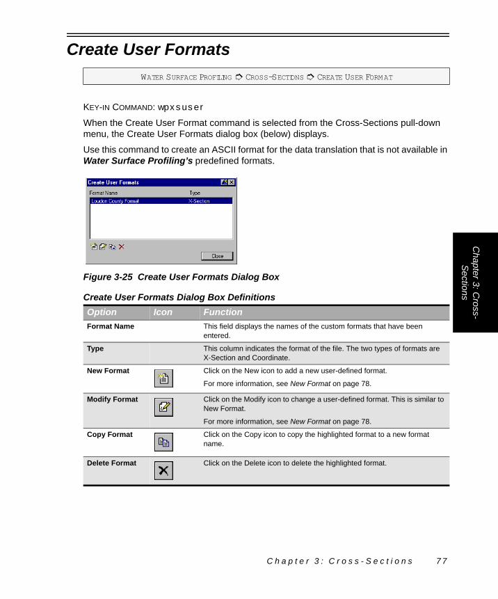
Chapter 3: C
ross-Sections
Create User Formats
KEY-IN COMMAND: wpxsuser
When the Create User Format command is selected from the Cross-Sections pull-down menu, the Create User Formats dialog box (below) displays.
Use this command to create an ASCII format for the data translation that is not available in Water Surface Profiling’s predefined formats.
WATER SURFACE PROFILING # CROSS-SECTIONS # CREATE USER FORMAT
Figure 3-25 Create User Formats Dialog Box
Create User Formats Dialog Box DefinitionsOption Icon FunctionFormat Name This field displays the names of the custom formats that have been
entered.
Type This column indicates the format of the file. The two types of formats are X-Section and Coordinate.
New Format Click on the New icon to add a new user-defined format.
For more information, see New Format on page 78.
Modify Format Click on the Modify icon to change a user-defined format. This is similar to New Format.
For more information, see New Format on page 78.
Copy Format Click on the Copy icon to copy the highlighted format to a new format name.
Delete Format Click on the Delete icon to delete the highlighted format.
C h a p t e r 3 : C r o s s - S e c t i o n s 7 7

New Format
To add a new format, click on the New User Format icon in the Create User Format dialog box (Figure 3-25 on page 77). Clicking on the Modify icon can also modify existing formats. Each line in the ASCII file to be transferred can contain up to 255 characters. The transfer format tells the program how the information for a point is arranged on each line.
After supplying a Format Name, enter the format by typing it directly into the Format edit field or by using the P, N, E, L, D, S, O, I, and R buttons. The number of characters entered into the edit field when using one of these buttons depends on the Field Width specified. For example, if 5 is set for the Field Width, five letter P’s display when the P button is selected.
WATER SURFACE PROFILING # CROSS-SECTIONS # CREATE USER FORMAT # NEW USER FORMAT
Figure 3-26 New User Format Dialog Box
New User Format Dialog Box DefinitionsOption FunctionFormat Name Type the name for the format being entered.
P Click on the P button to enter a character for point number.
N Click on the N button to enter a character for Northing.
E Click on the E button to enter a character for Easting.
L Click on the L button to enter a character for elevation.
D Click on the D button to enter a character for description.
S Click on the S button to enter a character for station.
O Click on the O button to enter a character for offset.
I Click on the I button to enter a character for instrument height.
R Click on the R button to enter a character for rod reading.
C Click on the C button to enter a character for comment.
Field Width Choose the Field Width to set a number for a character. The value in this edit field determines how many of the selected characters are placed.
7 8 W a t e r S u r f a c e P r o f i l i n g

Chapter 3: C
ross-Sections
View Cross-Section Graphics
KEY-IN COMMAND: wpxsview
ICON:
The View Cross-Section Graphics command loads the CAD graphic to display the Cross-Section Data. If the current CAD graphic that is being switched from has been modified, you are prompted to save changes to the CAD graphic.
Utilities that have been defined in the project also display in the Cross-Section CAD graphic. They are displayed according to the options set for each utility.
For more information, see Utility Annotation Settings on page 41.
Enter the desired station to view and click on Apply or use the arrow button to view the next or previous cross-section. If you enter a station value that has no corresponding cross-section station, the nearest station is found and displayed.
Cross-Section Settings
KEY-IN COMMAND: wpxsset
The Settings command allows you to set a vertical stretch factor for the cross-sections, tolerances used for extracting cross-sections and precision for cross slopes. This is also where you specify the Station at Center value for the cross-sections. The Station at Center value represents the station on the cross-section where the cross-section crosses the stream centerline.
Delimiter Select this button to place the delimeter specified in the type drop list. The available types are <space>, comma (,), colon (:), semicolon (;), [,], {,}, \, /, -, ^, and !.
Character Position
This field shows how many characters are behind the cursor.
Field Width This field shows how many characters are in a particular field.
WATER SURFACE PROFILING # CROSS-SECTIONS # VIEW CROSS-SECTION GRAPHICS
WATER SURFACE PROFILING # CROSS-SECTIONS # SETTINGS
New User Format Dialog Box DefinitionsOption Function
C h a p t e r 3 : C r o s s - S e c t i o n s 7 9

For more information about the vertical stretch factor and tolerance parameters, see Cross-Section Settings – General Tab (below). For more information on the precision settings, see Cross-Section Settings – Precision Tab on page 81.
Cross-Section Settings – General Tab
The Cross-Section Settings – General Tab (below) is used to set the Vertical Stretch Factor, Station At Stream Centerline value and the tolerance parameters for extracting cross-sections. The Vertical Stretch Factor applies a vertical exaggeration to the cross-section when viewing the CAD graphic. The values for the horizontal and vertical tolerance are set to selectively remove shots from the cross-section when reading the surface model data. Refer to Cross-Section Settings on page 51.
WATER SURFACE PROFILING # CROSS-SECTIONS # SETTINGS # GENERAL TAB
Figure 3-27 Cross Section Settings Dialog Box – General Tab
Cross Section Settings Dialog Box – General Tab DefinitionsOption FunctionVertical Stretch Factor
Set the vertical exaggeration when viewing the cross-section CAD graphic to an integer between 1 and 10.
Station at Stream Centerline
Set a value for the station along the cross-section line that represents the point of crossing the stream alignment. In HEC-2, all of the stations along the cross-section have to be positive. As a general rule, set this value so that none of the cross-section stations are negative if you plan on taking cross-sectional data into HEC-2.
Horizontal Tolerance
Enter the values for the horizontal tolerance to selectively remove points from the information being used to generate the cross-sections. This is useful when extracting cross-sections from dense surface models to reduce the number of points used for each section by removing redundant points.
For more information see Cross-Sections Concepts on page 48.
8 0 W a t e r S u r f a c e P r o f i l i n g

Chapter 3: C
ross-Sections
Cross-Section Settings – Precision Tab
The Cross-Section Settings Dialog Box – Precision Tab (below) sets the display precision for the slope reported in the Edit Cross-Section Data dialog box. This value is for display purposes only and is not used for any calculations. Type the slope precision values in the edit fields or use the slider control to set the precision of % Slope and H/V (V/H).
Vertical Tolerance
Enter the values for the vertical tolerance to selectively remove points from the information being used to generate the cross-sections. This is useful when extracting cross-sections from dense surface models to reduce the number of points used for each section by removing redundant points.
For more information see Cross-Sections Concepts on page 48.
WATER SURFACE PROFILING # CROSS-SECTIONS # SETTINGS # PRECISION TAB
Figure 3-28 Cross Section Settings Dialog Box – Precision Tab
Cross Section Settings Dialog Box – Precision Tab DefintionsOption Function% Slope Set the % Slope precision factor to an integer between 0 and 8 by typing the value in the
edit field or by using the slider control to set the precision factor.
H/V (V/H) Set the H/V (V/H) precision factor to an integer between 0 and 8 by typing the value in the edit field or by using the slider control to set the precision factor.
Cross Section Settings Dialog Box – General Tab DefinitionsOption Function
C h a p t e r 3 : C r o s s - S e c t i o n s 8 1

Synchronize Graphics and Data
KEY-IN COMMAND: wpxssync
This command can be accessed to verify that the graphic representation of a Water Surface Profiling object matches the numeric information. If differences exist, you determine whether the graphic or numeric information is correct. Clicking on the Update Graphics button writes the numeric information to the graphic. Clicking on the Update Data button writes the graphic information to the numeric.
This dialog box also automatically displays if Water Surface Profiling finds any differences when accessing a data set and corresponding graphic.
WATER SURFACE PROFILING # CROSS-SECTIONS # SYNCHRONIZE GRAPHICS AND DATA
Figure 3-29 Synchronize Graphics and Data Dialog Box
Synchronize Graphics and Data Dialog Box DefinitionsOption FunctionUpdate Graphics Click on this button to update the cross-section graphics in CAD from the numeric data.
Update Data After graphically modifying a Water Surface Profiling cross-section, use this command to update the numeric data based on the graphic changes.
8 2 W a t e r S u r f a c e P r o f i l i n g

C H A P T E R
4
T R A N S F E RIn this chapter:
Transfer Concepts. . . . . . . . . . . . . . . . . . . . . . . . . . . . 84
Export to HEC-RAS. . . . . . . . . . . . . . . . . . . . . . . . . . . 84
Import from HEC-RAS. . . . . . . . . . . . . . . . . . . . . . . . . 89
C h a p t e r 4 : T r a n s f e r 8 3
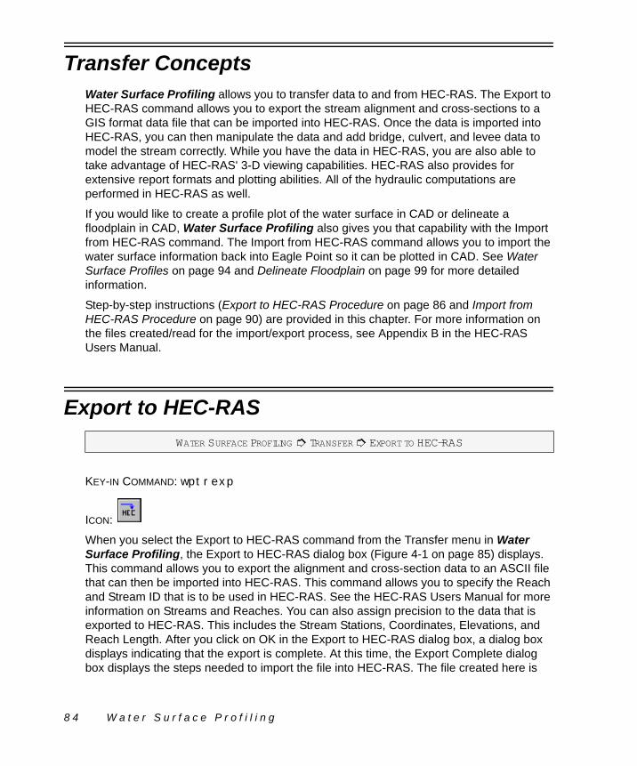
Transfer ConceptsWater Surface Profiling allows you to transfer data to and from HEC-RAS. The Export to HEC-RAS command allows you to export the stream alignment and cross-sections to a GIS format data file that can be imported into HEC-RAS. Once the data is imported into HEC-RAS, you can then manipulate the data and add bridge, culvert, and levee data to model the stream correctly. While you have the data in HEC-RAS, you are also able to take advantage of HEC-RAS' 3-D viewing capabilities. HEC-RAS also provides for extensive report formats and plotting abilities. All of the hydraulic computations are performed in HEC-RAS as well.
If you would like to create a profile plot of the water surface in CAD or delineate a floodplain in CAD, Water Surface Profiling also gives you that capability with the Import from HEC-RAS command. The Import from HEC-RAS command allows you to import the water surface information back into Eagle Point so it can be plotted in CAD. See Water Surface Profiles on page 94 and Delineate Floodplain on page 99 for more detailed information.
Step-by-step instructions (Export to HEC-RAS Procedure on page 86 and Import from HEC-RAS Procedure on page 90) are provided in this chapter. For more information on the files created/read for the import/export process, see Appendix B in the HEC-RAS Users Manual.
Export to HEC-RAS
KEY-IN COMMAND: wptrexp
ICON:
When you select the Export to HEC-RAS command from the Transfer menu in Water Surface Profiling, the Export to HEC-RAS dialog box (Figure 4-1 on page 85) displays. This command allows you to export the alignment and cross-section data to an ASCII file that can then be imported into HEC-RAS. This command allows you to specify the Reach and Stream ID that is to be used in HEC-RAS. See the HEC-RAS Users Manual for more information on Streams and Reaches. You can also assign precision to the data that is exported to HEC-RAS. This includes the Stream Stations, Coordinates, Elevations, and Reach Length. After you click on OK in the Export to HEC-RAS dialog box, a dialog box displays indicating that the export is complete. At this time, the Export Complete dialog box displays the steps needed to import the file into HEC-RAS. The file created here is
WATER SURFACE PROFILING # TRANSFER # EXPORT TO HEC-RAS
8 4 W a t e r S u r f a c e P r o f i l i n g

Chapter 4: Transfer
then imported into HEC-RAS by selecting Import Geometry Data ! GIS Data from the Geometry Editor in HEC-RAS. See Export to HEC-RAS Procedure on page 86 for step-by-step instructions on exporting alignment and cross-section data to HEC-RAS.
Figure 4-1 Export To HEC-RAS Dialog Box
Export to HEC-RAS Dialog Box DefinitionsOption Icon FunctionFile Type the path to which you would like the geometry data exported. By
default the file is placed in your project directory with a name of DRAWINGNAME.GEO, where DRAWINGNAME is the name of the CAD drawing or design file. You can also use the folder icon to the right of the edit field to bring up the file selection dialog box.
Stream ID Enter a description for the Stream ID to be used in HEC-RAS. This identifies the overall stream which may have several reaches. The description can be up to 16 characters long. By default Eagle Point uses the first 16 characters of the subproject description.
Reach ID Enter the description for the individual reach to be used in HEC-RAS. The description can be up to 16 characters long. By default Eagle Point uses the first 16 characters of the subproject description.
Export Precision You can set the precision of the values exported to HEC-RAS. The Stream Stations, Coordinates, Elevations, and Reach Length precision can be set before exporting the data. You can either directly enter the precision values in the edit fields or use the slider bars.
C h a p t e r 4 : T r a n s f e r 8 5

Export to HEC-RAS ProcedureBelow is the step-by-step procedure for taking alignment and cross-section data from Water Surface Profiling into HEC-RAS:
1. Select Alignments ! Edit Data or Alignments ! Convert Objects to Stream Alignment in Water Surface Profiling.
2. Enter the Stream Alignment data.3. Select Cross-Sections ! Edit Data, or Cross-Sections ! Extract from Surface
Model or Cross-Sections ! Import in Water Surface Profiling.4. Enter the cross-sectional data.5. Select Transfer ! Export to HEC-RAS.6. Verify the path for the file that is created.7. Enter the Stream ID and Reach ID to use in HEC-RAS.8. Verify the precision settings.9. Click on OK to write the alignment and cross-section data to a file.10. Click on the Load HEC-RAS button in the Export Complete dialog box or
double-click on the HEC-RAS icon on the Windows desktop to start HEC-RAS.
Figure 4-2 Export Complete Dialog Box
Export Complete Dialog Box DefinitionsOption FunctionListing This contains the general steps needed to take the file created by the Export to HEC-RAS
command into HEC-RAS. See the Export to HEC-RAS Procedure steps (below) for more information.
Load HEC-RAS This button launches the HEC-RAS program. You can then follow the steps in the listing to take the file created into HEC-RAS.
8 6 W a t e r S u r f a c e P r o f i l i n g

Chapter 4: Transfer
When HEC-RAS opens, it should resemble the figure shown below.
11. Select Edit ! Geometric Data.The Geometric Data dialog box (below) displays.
12. Select File ! Import Geometry Data ! GIS Format.
Figure 4-3 HEC-RAS Dialog Box
Figure 4-4 Geometric Data Dialog Box
C h a p t e r 4 : T r a n s f e r 8 7

The Import #GIS Format data file dialog box (below) displays.
13. Enter a description for the geometry data in the Title edit field.
" You could use the subproject description used in Water Surface Profiling for the data being imported, as a suggestion.
14. Select the .GEO file that was created by using the Export to HEC-RAS command.
15. Click on OK.The data is read into HEC-RAS. At this point the alignment data and cross-section data are in HEC-RAS.
We need to save the HEC-RAS project to a directory and give it a project description.
16. In HEC-RAS, select File ! Save Project As.The Save Project As dialog box (below) displays.
17. In the Title edit field, enter a description for the reach geometry you just imported.
18. For the File Name, enter a file name using the .PRJ extension.
Figure 4-5 Import #GIS Format Data File Dialog Box
Figure 4-6 Save Project As Dialog Box
8 8 W a t e r S u r f a c e P r o f i l i n g

Chapter 4: Transfer
$ Make sure you do not put the file into your project directory. Create a HEC-RAS directory below your project directory and put it there. Some of the HEC-RAS files that are created interfere with Eagle Point’s surface modeling files.
19. Click on OK.The project is saved with the imported geometry data.
You can now proceed with using HEC-RAS to enter the flow data and additional geometry information including bridges, culverts and levees. The calculation of the water surface profiles can also be performed now that the basic geometry data has been imported into HEC-RAS.
Import from HEC-RAS
KEY-IN COMMAND: wptrimp
ICON:
The Import from HEC-RAS command allows you to import the HEC-RAS profile and floodplain delineation information back into Eagle Point. Once the data is imported in, you can use the commands in the Output menu to draw the profile and floodplain delineation’s into CAD. The file that is imported is the HEC-RAS GIS file. This file can be created in HEC-RAS by selecting the Export GIS Data command in the File menu in HEC-RAS. After the file is created in HEC-RAS, the file is imported into Eagle Point by selecting the Import from HEC-RAS command. The Import from HEC-RAS dialog box (Figure 4-7 on page 90) displays. After the file is selected and you click on OK, the Select Stream/Reach dialog box displays if more than one reach was defined in HEC-RAS. This dialog box allows you to choose which stream-reach to import. All associated profiles for the selected reach are then imported. See Import from HEC-RAS Procedure on page 90 for a step-by-step procedure on importing the HEC-RAS data.
WATER SURFACE PROFILING # TRANSFER # IMPORT FROM HEC-RAS
C h a p t e r 4 : T r a n s f e r 8 9

" Eagle Point can only import one reach per sub-project from your HEC-RAS project. If your HEC-RAS project contains more than one reach, you are prompted to select which stream-reach to import. You need to create additional Water Surface Profiling subprojects to import the other stream-reaches.
Enter the path for the GIS file created in HEC-RAS. You can also select the folder icon to the right of the edit field to bring up the file selection dialog box. The file that is to be selected has a default extension of .GIS.
All of the Stream-Reaches are listed for the HEC-RAS project. Select the Stream-Reach you would like to import the data for.
Import from HEC-RAS ProcedureFollowing is the procedure to take the HEC-RAS profile and floodplain data back into Water Surface Profiling. Once the data is imported, you can use the commands in the Output menu to create water surface profile plots in CAD as well as create floodplain delineations in CAD.
1. From the HEC-RAS main dialog box, select File ! Export GIS Data.
Figure 4-7 Import From HEC-RAS Dialog Box
Figure 4-8 Select Stream/Reach To Import Dialog Box
9 0 W a t e r S u r f a c e P r o f i l i n g

Chapter 4: Transfer
The GIS Export dialog box (below) displays.
2. In the GIS Export dialog box, specify the directory and file name for the GIS file being exported. By default, the HEC-RAS project directory is displayed in the Export File edit field.
3. To specify the water surface profiles to be exported out of HEC-RAS click on the Select Profiles to Export button.
4. After the profiles have been selected, toggle on Export User Defined Cross Sections.
5. Toggle on Export Interpolated Cross Sections.6. Turn on the Entire Cross Section radio button in the Cross Section Export
Options section.7. Click on the Export Data button.
The data from HEC-RAS has been saved to the specified file.
We are now ready to import the data from the file just created into Water Surface Profiling.
8. In Water Surface Profiling, select Transfer ! Import from HEC-RAS.The Import from HEC-RAS dialog box (below) displays.
9. Select the file that was just created from HEC-RAS using the file selection icon located to the right of the HEC-RAS GIS File edit field.
Figure 4-9 GIS Export Dialog Box
Figure 4-10 Import From HEC-RAS Dialog Box
C h a p t e r 4 : T r a n s f e r 9 1

10. After the file is selected, click on OK.
If you have more than one reach defined in HEC-RAS, the Select Stream/Reach to Import dialog box (above) displays.
11. Select the Stream-Reach file to import.12. Click on OK.The water surface profile and floodplain data is then imported in Water Surface Profiling. The data can be plotted and viewed by running the Water Surface Profiling and Delineate Floodplain commands in the Output menu.
Figure 4-11 Select Stream/Reach To Import Dialog Box
9 2 W a t e r S u r f a c e P r o f i l i n g

C H A P T E R
5
O U T P U TOnce the data has been adjusted in HEC-RAS, computations run and imported back from HEC-RAS, the commands in the Output menu allow you to create some output. Here you can create water surface profiles in CAD and generate floodplain delineations in CAD as well. You can also define a sub-project prototype so that all of the settings are saved to a prototype name. This allows you to avoid having to set all of the settings every time a project/sub-project is started.
Other printed reports and cross-section plots should be developed using the tools in HEC-RAS.
In this chapter:
Water Surface Profiles . . . . . . . . . . . . . . . . . . . . . . . . 94
Delineate Floodplain . . . . . . . . . . . . . . . . . . . . . . . . . . 99
Sub-project Prototype Settings . . . . . . . . . . . . . . . . . 101
C h a p t e r 5 : O u t p u t 9 3

Water Surface Profiles
KEY-IN COMMAND: wpprof
ICON:
The water surface profiles that are generated in CAD do not include the structures. Only the water surface profiles themselves are plotted. All of the cross-section locations are noted along with any utility locations. The utilities that were defined using the Manage Utilities command (see Manage Utilities on page 38) display in the profile. CAD settings can be specified for each profile so that you can conveniently turn items on and off if needed. The figure below shows an example of the water surface profile plot.
When you select the Water Surface Profiles command from the Output menu, the Water Surface Profiles dialog box (below) displays. Here you are able to specify CAD settings for each profile that is imported from HEC-RAS. Markers are also placed to indicate the
WATER SURFACE PROFILING # OUTPUT # WATER SURFACE PROFILES
Figure 5-1 Water Surface Profile Example
9 4 W a t e r S u r f a c e P r o f i l i n g

Chapter 5: O
utput
cross-section locations. These have their own CAD settings as well. Besides the CAD settings, you can also modify the profile names in the listing and copy profiles.Figure 5-2 Water Surface Profiles Dialog Box
Water Surface Profiles Dialog Box DefinitionsOption Icon FunctionProfile Number (No.)
This is the profile number. The first profile is always the Channel Invert.
Profile This is a description of the profile. The first profile is always Channel Invert. All of the profiles after the Channel Invert profile have the descriptions used in HEC-RAS.
Modify Profile This option allows you to modify the profile name in the listing. See Modify Profile (below) for more information.
Profile CAD Settings
This icon launches the CAD Settings dialog box which allows you to change the layer/level, color, weight, and linetype/linestyle of the profiles, overbanks and cross-section markers.
For more information, see CAD Settings in the Getting Started manual.
Settings You can modify how the profile is plotted, left to right or right to left. There is also a setting for placing the water surface profile plot into the project’s plan drawing as well. You can also toggle whether to display sewer networks in the profile to check clearances.
See Water Surface Profile Settings on page 96 for more information.
View Profile Graphic
This loads the profile drawing/design file in CAD. Depending on the toggle in Profile Settings, either the plan CAD graphic or Water Surface Profile CAD graphic is loaded.
For more information, see Profile Settings – General Tab on page 96.
Preview Profile Graphic
This displays the water surface profile to a Windows dialog box. Using this option does not require CAD to be loaded. See Preview Objects in the Eagle Point Menu manual for more information.
C h a p t e r 5 : O u t p u t 9 5

Modify Profile
Use this command if you want to modify the profile names that were imported from HEC-RAS. This command modifies the profile names that are displayed in the Water Surface Profiling listing as well as in the Delineate Floodplain profile listing. See Delineate Floodplain on page 99. When you click on the Modify Profile icon in the Water Surface Profiles dialog box, the Modify Profile dialog box (below) displays.
A description of the currently highlighted profile displays in the Profile edit field. You can modify this name to another unique name.
Water Surface Profile Settings
The Settings command provides access to various settings that Water Surface Profiling uses when displaying Water Surface Profiles. You can set the Profile direction and the CAD graphic that the profile displays in.
For additional information see Profile Settings – General Tab (below) and Profile Settings – Sewer Display Tab on page 98.
Profile Settings – General Tab
On the General tab you can set the direction the profile is drawn and where it is drawn. The default location for the profile is in its own CAD drawing. You can specify a profile
WATER SURFACE PROFILING # OUTPUT # WATER SURFACE PROFILES # MODIFY PROFILE
Figure 5-3 Modify Profile Dialog Box
WATER SURFACE PROFILING # OUTPUT # WATER SURFACE PROFILES # SETTINGS
WATER SURFACE PROFILING # OUTPUT # WATER SURFACE PROFILES # SETTINGS # GENERAL TAB
9 6 W a t e r S u r f a c e P r o f i l i n g

Chapter 5: O
utput
coordinate system (PCS) in the plan drawing and have the profile drawn there. The profile can also be drawn so that the stationing goes from left to right (default) or from right to left.Define Coordinate System
By selecting this option, you can create a profile coordinate system in the sub-project plan drawing/design file in which to display the profile graphic. The elements that comprise the profile coordinate system include the X and Y value of the reference point, station and elevation of the reference point, and the direction of the profile. When you select a reference point, you are establishing that the point specified has a certain station and elevation. When the profiles are drawn they are based on this reference point.
Figure 5-4 Water Surface Profile Settings Dialog Box – General Tab
Water Surface Profile Settings Dialog Box – General Tab DefinitionsOption FunctionProfile Orientation
These radio buttons switch between displaying the profile graphic with increasing stationing, going from left to right or right to left.
Draw Profile Graphic
These radio buttons allow you to choose the CAD graphic into which you place the profile graphic. If you choose to draw the profile in the sub-project plan CAD graphic, you must define the profile coordinate system in which the profile resides.
For more information see Define Coordinate System (below).
Define Coordinate System
This option allows you to create a profile coordinate system in the sub-program plan drawing/design in which you can display your graphic.
Precision The Precision option allows you set the precision for angular, linear, planimetric area, stations, offsets, dry volume, and wet volume.
WATER SURFACE PROFILING # OUTPUT # WATER SURFACE PROFILES # SETTINGS # GENERAL TAB # DEFINE COORDINATE SYSTEM
C h a p t e r 5 : O u t p u t 9 7

You can either enter the coordinates for the reference point or graphically pick the point in the CAD window using the PIC button.
Before adding a PCS, make sure the horizontal and vertical scales for the project are set correctly. To set these values, select Tools ! Plot Scales from the Eagle Point menu. Changing the Scales setting after you add a PCS does not update existing profiles. These scales directly affect the Horizontal and Vertical scales of the profile. The Define Coordinate System dialog box is shown below.
Profile Settings – Sewer Display Tab
The Sewer Display tab displays any storm and sanitary sewer networks that are part of the project. By default, the networks are toggled on to be displayed in the profile. When you click on the Sewer Display Tab, the Water Surface Profile Settings dialog box (below) displays.
Figure 5-5 Define Coordinate System Dialog Box
Define Coordinate System Dialog Box DefinitionsOption FunctionLocation of Reference Point
You can directly enter the X, Y coordinate values for the reference point, or use the PIC button to graphically select the point in the CAD window. When you graphically select the point, the coordinate values are displayed in the corresponding edit fields. Keep in mind that this reference point may not be on the profile. You are just specifying that a particular point in the CAD graphic is at a specific station and elevation.
PIC Use this button to graphically select the Reference X and Y values from the CAD graphic. This button enables when focus is put in the X or Y edit fields.
Station Enter the station of the reference point in this edit field.
Elevation Specify the elevation of the reference point in this edit field.
WATER SURFACE PROFILING # OUTPUT # WATER SURFACE PROFILES # SETTINGS # SEWER DISPLAY TAB
9 8 W a t e r S u r f a c e P r o f i l i n g

Chapter 5: O
utput
In order for the sewer projects to display in the Sewer Display tab, the sewer profiles have to have been created using the same profile coordinate system as the water surface profile. Also, the sewer networks must have been toggled on in Storm Sewers/Sanitary Sewers to be referenced back into the Water Surface Profiling profile.The referenced sewer networks are listed in the Sewer Display tab. A check mark to the left of the reach indicates that it is displayed in the water surface profile. The reach for a particular sewer network does not display here if the profile PCS of the sewer network does not match the PCS of the water surface profile.
Delineate Floodplain
KEY-IN COMMAND: wpflood
ICON:
Figure 5-6 Water Surface Profile Settings Dialog Box – Sewer Display Tab
WATER SURFACE PROFILING # OUTPUT # DELINEATE FLOODPLAIN
C h a p t e r 5 : O u t p u t 9 9

The Delineate Floodplain command allows you to show the water extents for various water surface profiles in CAD. You can set individual CAD settings for each delineation created. Figure 5-7 (below) shows an example of the floodplain delineation.
This command allows you to create a 2-D polyline/line string that sets the limits of the water surface for a particular water surface profile. The delineation reflects the locations of structures and levees in the reach and stream. You can also show the limits of the cross-sections. Each of these items delineated have their own CAD settings. When you select the Delineate Floodplain command from the Output menu in Water Surface Profiling, the Delineate Floodplain dialog box (below) displays.
Figure 5-7 Delineate Floodplain Example
Figure 5-8 Delineate Floodplain Dialog Box
Delineate Floodplain Dialog Box DefinitionsOption Icon FunctionWater Surface This drop list lists all of the profile names that were imported from HEC-
RAS. Select the water surface for which you want to delineate the profile.
1 0 0 W a t e r S u r f a c e P r o f i l i n g

Chapter 5: O
utput
Sub-project Prototype Settings
KEY-IN COMMAND: wpprotoset
The Sub-project Prototype Settings command allows you to save settings than can be used for all of your Water Surface Profiling sub-projects that are created. The settings that are saved include all of the general settings including the alignment, cross-section and output settings that have been specified. All of the settings are saved to a central location, so when you create a new sub-project, you can specify the desired prototype to
Place Floodplain When this is toggled on, the floodplain for the selected profile is delineated using the CAD settings for the specific profile.
Place Cross-Section Boundary
When this is toggled on, the boundary of the cross-sections is delineated using the CAD settings specified for the boundary.
Erase Existing Floodplain
When this is toggled on, the floodplain for the selected profile is deleted before the new floodplain is drawn. If the Place Floodplain toggle is off and this toggle is on, the command merely erases the corresponding profile’s floodplain delineation.
Erase Existing Cross-Section Boundary
When this is toggled on, the cross-section boundary is deleted before the new cross-section boundary is drawn. If the Place Cross-section Boundary toggle is off and this toggle is on, the command merely erases the cross-section boundary.
CAD Settings Clicking on this icon launches the CAD Settings dialog box, which allows you to change the layer/level, color, weight, and linetype/linestyle for the floodplain delineation and cross-section boundary.
For more information, see CAD Settings in the Getting Started manual.
WATER SURFACE PROFILING # OUTPUT # SUB-PROJECT PROTOTYPE SETTINGS
Delineate Floodplain Dialog Box DefinitionsOption Icon Function
C h a p t e r 5 : O u t p u t 1 0 1

use. This allows you to establish settings that are commonly used so you do not have to change settings for every sub-project that is created.
New Sub-project Prototype
The New Sub-project Prototype command allows you to create a prototype for sub-projects. All of the settings for Alignments, Cross-sections, and Output are saved to the name specified. These settings are stored in a central location that is available for all projects.
Prototype Description is the name of the sub-project prototype. This name displays in the Sub-project Prototype Settings dialog box and when adding in a new sub-project with the New command found in the File menu of the Eagle Point main menu.
Figure 5-9 Sub-project Prototype Settings Dialog Box
Sub-project Prototype Settings Dialog Box DefinitionsOption Icon FunctionNew Sub-project Prototype
This allows you to create a prototype for sub-projects. All of the settings for Alignments, Cross-sections, and Output are saved to a central location.
For more information, see New Sub-project Prototype (below).
Delete Sub-project Prototype
This allows you to remove the highlighted sub-project prototype from the listing. You cannot remove the top two Default sub-project prototypes.
WATER SURFACE PROFILING # OUTPUT # SUB-PROJECT PROTOTYPE SETTINGS # NEW SUB-PROJECT PROTOTYPE
Figure 5-10 New Sub-project Prototype Dialog Box
1 0 2 W a t e r S u r f a c e P r o f i l i n g

Chapter 5: O
utput
C h a p t e r 5 : O u t p u t 1 0 3

1 0 4 W a t e r S u r f a c e P r o f i l i n g
I N D E X
Symbols# . . . . . . . . . . . . . . . . . . . . . . . . . . . . . . . . . . . . 55% Slope . . . . . . . . . . . . . . . . . . . . . . . . . . . . . . 81
Numerics360 Degree Method For Measuring Skew
Angle . . . . . . . . . . . . . . . . . . . . . . . . . . . . 49
AActual Station . . . . . . . . . . . . . . . . . . . . . . . . . 75Alignment . . . . . . . . . . . . . . . . . . . . . . . 19, 35, 37
Edit Alignment Data . . . . . . . . . . . . . . . . . 19Alignment Concepts . . . . . . . . . . . . . . . . . . . . 16
Cross-Section Alignment Definitions . . . . 16Cross-sectional Alignment . . . . . . . . . . . . 18Overbank Alignments . . . . . . . . . . . . . . . . 17Stream Alignment Definitions . . . . . . . . . . 16Stream Alignments . . . . . . . . . . . . . . . . . . 17
Alignment Listing . . . . . . . . . . . . . . . . . . . . . . . 29Alignment Name . . . . . . . . . . . . . . . . . . . . . . . 33Alignments . . . . . . . . . . . . . . . . . . . . . . . . . . . . 15
Alignment Concepts . . . . . . . . . . . . . . . . . 16Associate Alignment . . . . . . . . . . . . . . . . . 33Convert Objects to Cross-Section
Alignment . . . . . . . . . . . . . . . . . . . . . 36Convert Objects to Stream Alignment . . . 35Manage Alignments . . . . . . . . . . . . . . . . . 30Manage Utilities . . . . . . . . . . . . . . . . . . . . 38View Alignment Graphics . . . . . . . . . . . . . 44
Angle . . . . . . . . . . . . . . . . . . . . . . . . . . . . . 20, 23Annotate Cross-Sections . . . . . . . . . . . . . . . . . 68
Annotate Cross-Sections Dialog Box . . . . 69Annotate Cross-Sections Example . . . . . . 69
Annotate Cross-Sections Dialog Box . . . . . . . . 69Annotate Cross-Sections Example . . . . . . . . . 69Annotation . . . . . . . . . . . . . . . . . . . . . . . . . . . . 42Annotation Placement . . . . . . . . . . . . . . . . . . . 42Annotation Settings . . . . . . . . . . . . . . . . . . . . . 40Assign Points to Station . . . . . . . . . . . . . . . . . . 74
Assign Points to Station Dialog Box . . . . . 75
Assign Points to Station Dialog Box . . . . . . . . 75Assign Station . . . . . . . . . . . . . . . . . . . . . . . . . 75Associate Alignment . . . . . . . . . . . . . . . . . 32, 33
Associate Alignment Dialog Box . . . . . . . 34Associate Alignment Dialog Box . . . . . . . . . . . 34AZ . . . . . . . . . . . . . . . . . . . . . . . . . . . . . . . . . . 58
BBC (Begin Curve) Station . . . . . . . . . . . . . . . . 26Begin Station . . . . . . . . . . . . . . . . . . . . . . . . . . 59Beginning Station . . . . . . . . . . . . . . . . . . . 27, 35Build List . . . . . . . . . . . . . . . . . . . . . . . . . . 58, 67Build Station List . . . . . . . . . . . . . . . . . . . . . . . 58
Build Station List Dialog Box . . . . . . . . . . 58Build Station List Dialog Box . . . . . . . . . . . . . . 58
CC . . . . . . . . . . . . . . . . . . . . . . . . . . . . . . . . 26, 78CAD Settings . . . . . . . . . . . . . . . . 20, 31, 69, 101Character Position . . . . . . . . . . . . . . . . . . . . . . 79Choose Destination Location Dialog Box . . . . . 5Concepts . . . . . . . . . . . . . . . . . . . . . . . . . . . . . . 1
HEC-RAS Overview . . . . . . . . . . . . . . . . . . 7Installing HEC-RAS . . . . . . . . . . . . . . . . . . 2Introduction . . . . . . . . . . . . . . . . . . . . . . . . 2Previous Users of Eagle Point’s Water
Surface Profiling Module . . . . . . . . . . 10Typical Project Flow . . . . . . . . . . . . . . . . . 12
Convert Objects to Cross-Section Alignment . 36Convert Objects To Cross-Section
Alignment Dialog Box . . . . . . . . . . . . 37QuickSteps . . . . . . . . . . . . . . . . . . . . . . . . 37
Convert Objects To Cross-Section Alignment Dialog Box . . . . . . . . . . . . . . . . 37
Convert Objects to Stream Alignment . . . . . . . 35Convert Objects To Stream Alignment
Dialog Box . . . . . . . . . . . . . . . . . . . . 35QuickSteps . . . . . . . . . . . . . . . . . . . . . . . . 36
Convert Objects To Stream Alignment Dialog Box . . . . . . . . . . . . . . . . . . . . . . . . 35
I n d e x 1 0 5
Convert Objects to Utility . . . . . . . . . . . . . . . . 40Converting Old Projects . . . . . . . . . . . . . . . . . 10Copy Format . . . . . . . . . . . . . . . . . . . . . . . . . . 77Copy Stream Station . . . . . . . . . . . . . . . . . . . . 55Corridor Edge Left . . . . . . . . . . . . . . . . . . . . . 66Corridor Edge Right . . . . . . . . . . . . . . . . . . . . 66Create User Formats . . . . . . . . . . . . . . . . . . . 77
Create User Formats Dialog Box . . . . . . . 77New Format . . . . . . . . . . . . . . . . . . . . . . . 78
Create User Formats Dialog Box . . . . . . . . . . 77Cross Section Settings Dialog Box –
General Tab . . . . . . . . . . . . . . . . . . . . . . . 80Cross Section Settings Dialog Box –
Precision Tab . . . . . . . . . . . . . . . . . . . . . . 81Cross-Section Alignment Definitions . . . . . . . . 16
Cross-Section Alignment Types . . . . . . . 16Cross-section Alignment Station at Center
Setting Location . . . . . . . . . . . . . . . . . . . 18Cross-Section Alignment Types . . . . . . . . . . . 16Cross-Section Angle from parallel tolerance . . 42Cross-Section Display Distance . . . . . . . . . . . 42Cross-Section Number . . . . . . . . . . . . . . . . . . 69Cross-Section Settings . . . . . . . . . . . . . . . 51, 79
Cross-Section Settings – General Tab . . 80Cross-Section Settings – Precision Tab . 81Horizontal And Vertical Curve Tolerance . 51
Cross-Section Settings – General Tab . . . . . . 80Cross Section Settings Dialog Box –
General Tab . . . . . . . . . . . . . . . . . . . 80Cross-Section Settings – Precision Tab . . . . . 81
Cross Section Settings Dialog Box – Precision Tab . . . . . . . . . . . . . . . . . . 81
Cross-Section Stationing . . . . . . . . . . . . . . . . 50Cross-Section Stationing Example . . . . . 50
Cross-Section Stationing Example . . . . . . . . . 50Cross-Section Types . . . . . . . . . . . . . . . . . . . . 48Cross-sectional Alignment . . . . . . . . . . . . . . . 18
Cross-section Alignment Station at Center Setting Location . . . . . . . . 18
Cross-Sections . . . . . . . . . . . . . . . . . . . . . . . . 47Annotate Cross-Sections . . . . . . . . . . . . . 68Create User Formats . . . . . . . . . . . . . . . . 77Cross-Section Settings . . . . . . . . . . . . . . 79Cross-Sections Concepts . . . . . . . . . . . . 48Edit Cross-Section Data . . . . . . . . . . . . . 53Export Cross-Sections . . . . . . . . . . . . . . . 76Extract Cross-Sections . . . . . . . . . . . . . . 64Import Cross-Sections . . . . . . . . . . . . . . . 70Synchronize Graphics and Data . . . . . . . 82
View Cross-Section Graphics . . . . . . . . . .79Cross-Sections Concepts . . . . . . . . . . . . . . . . .48
Cross-Section Settings . . . . . . . . . . . . . . .51Cross-Section Stationing . . . . . . . . . . . . . .50Cross-Section Types . . . . . . . . . . . . . . . . .48Import/Export Data . . . . . . . . . . . . . . . . . .51Skewed Cross-Sections . . . . . . . . . . . . . .48
Curve Data . . . . . . . . . . . . . . . . . . . . . . . . . . . .20Curve Stationing Interval . . . . . . . . . . . . . . . . .59Curve Stations . . . . . . . . . . . . . . . . . . . . . . . . .59
DD . . . . . . . . . . . . . . . . . . . . . . . . . . . . . . . . . . . .78Da . . . . . . . . . . . . . . . . . . . . . . . . . . . . . . . . . . .26Dc . . . . . . . . . . . . . . . . . . . . . . . . . . . . . . . . . . .26Define Coordinate System . . . . . . . . . . . . . . . .97
Define Coordinate System Dialog Box . . .98Define Coordinate System Dialog Box . . . . . . .98Defined . . . . . . . . . . . . . . . . . . . . . . . . . . . . . . .39Defined Alignments . . . . . . . . . . . . . . . . . .36, 37Delete Alignment . . . . . . . . . . . . . . . . . . . . . . .31Delete Existing Stations . . . . . . . . . . . . . . . . . .59Delete Format . . . . . . . . . . . . . . . . . . . . . . . . . .77Delete PI . . . . . . . . . . . . . . . . . . . . . . . . . . . . . .20Delete Shot . . . . . . . . . . . . . . . . . . . . . . . . . . . .56Delete Stream Station . . . . . . . . . . . . . . . .55, 67Delete Sub-project Prototype . . . . . . . . . . . . .102Delete Utility . . . . . . . . . . . . . . . . . . . . . . . . . . .39Delimiter . . . . . . . . . . . . . . . . . . . . . . . . . . . . . .79Delineate Floodplain . . . . . . . . . . . . . . . . . . . . .99
Delineate Floodplain Dialog Box . . . . . . .100Delineate Floodplain Example . . . . . . . .100
Delineate Floodplain Dialog Box . . . . . . . . . .100Delineate Floodplain Example . . . . . . . . . . . .100Details . . . . . . . . . . . . . . . . . . . . . . . . . . . . . . .45Diameter . . . . . . . . . . . . . . . . . . . . . . . . . . .39, 41Direction . . . . . . . . . . . . . . . . . . . . . . . . . . . . . .24Display Stations . . . . . . . . . . . . . . . . . . . . . . . .56Display Stations and Preview . . . . . . . . . . . . . .56Display Stations, Preview and Shots . . . . . . . .57Distance . . . . . . . . . . . . . . . . . . . . .20, 23, 24, 62DL . . . . . . . . . . . . . . . . . . . . . . . . . . . . . . . . . . .58DL And DR For Measuring Skew Angles . . . . .49DR . . . . . . . . . . . . . . . . . . . . . . . . . . . . . . . . . .58Draw Profile Graphic . . . . . . . . . . . . . . . . . . . .97Drawing Path . . . . . . . . . . . . . . . . . . . . . . . . . .31
1 0 6 W a t e r S u r f a c e P r o f i l i n g

EE . . . . . . . . . . . . . . . . . . . . . . . . . . . . . . . . 26, 78Easting . . . . . . . . . . . . . . . . . . . 20, 23, 24, 28, 73EC (End Curve) Station . . . . . . . . . . . . . . . . . . 26Edit Alignment Data . . . . . . . . . . . . . . . . . . . . . 19
Edit Alignment Data Dialog Box . . . . . . . . 19Edit Alignment Data Dialog Box – Angle
and Distance View . . . . . . . . . . . . . . 21Edit Alignment Data Dialog Box –
Coordinate View . . . . . . . . . . . . . . . . 21Edit Alignment Data Dialog Box
Definitions . . . . . . . . . . . . . . . . . . . . . 19Horizontal Curve Data . . . . . . . . . . . . . . . 24Modify PI . . . . . . . . . . . . . . . . . . . . . . . . . 23New PI . . . . . . . . . . . . . . . . . . . . . . . . . . . 21Preview Alignment Graphics . . . . . . . . . . 28Print Alignment Reports . . . . . . . . . . . . . . 29Reference Station . . . . . . . . . . . . . . . . . . . 27Station Data . . . . . . . . . . . . . . . . . . . . . . . 27
Edit Alignment Data Dialog Box . . . . . . . . . . . . 19Edit Alignment Data Dialog Box – Angle and
Distance View . . . . . . . . . . . . . . . . . . . . . . 21Edit Alignment Data Dialog Box – Coordinate
View . . . . . . . . . . . . . . . . . . . . . . . . . . . . . 21Edit Alignment Data Dialog Box Definitions . . . 19Edit Cross-Section Data . . . . . . . . . . . . . . . . . 53
Build Station List . . . . . . . . . . . . . . . . . . . . 58Edit Cross-Section Data/Display
Stations and Preview Dialog Box . . . 54Edit Cross-Section Data/Display
Stations Dialog Box . . . . . . . . . . . . . . 55Edit Cross-Section/Display Stations,
Preview and Shots Data Dialog Box . 54New Shot . . . . . . . . . . . . . . . . . . . . . . . . . 59New Stream Station . . . . . . . . . . . . . . . . . 57Query Cross-Section . . . . . . . . . . . . . . . . 63
Edit Cross-Section Data/Display Stations and Preview Dialog Box . . . . . . . . . . . . . . 54
Edit Cross-Section Data/Display Stations Dialog Box . . . . . . . . . . . . . . . . . . . . . . . . 55
Edit Cross-Section/Display Stations, Preview and Shots Data Dialog Box . . . . . 54
Edit File . . . . . . . . . . . . . . . . . . . . . . . . . . . . . . 71Elevation . . . . . . . . . . . . . . 56, 60, 61, 64, 73, 98Elevation Type . . . . . . . . . . . . . . . . . . . . . . 39, 40End Station . . . . . . . . . . . . . . . . . . . . . . . . . . . 59Erase Existing Cross-Section Boundary . . . . 101Erase Existing Floodplain . . . . . . . . . . . . . . . 101
Explanation Of RHF Convention . . . . . . . . . . . 50Export Complete Dialog Box . . . . . . . . . . . . . . 86Export Cross-Sections . . . . . . . . . . . . . . . . . . 76
Export Cross-Sections Dialog Box . . . . . . 76Export Cross-Sections Dialog Box . . . . . . . . . 76Export Precision . . . . . . . . . . . . . . . . . . . . . . . 85Export to HEC-RAS . . . . . . . . . . . . . . . . . . . . . 84
Export Complete Dialog Box . . . . . . . . . . 86Export To HEC-RAS Dialog Box . . . . . . . 85Export to HEC-RAS Procedure . . . . . . . . 86
Export To HEC-RAS Dialog Box . . . . . . . . . . . 85Export to HEC-RAS Procedure . . . . . . . . . . . . 86
Geometric Data Dialog Box . . . . . . . . . . . 87HEC-RAS Dialog Box . . . . . . . . . . . . . . . 87Import #GIS Format Data File Dialog
Box . . . . . . . . . . . . . . . . . . . . . . . . . . 88Save Project As Dialog Box . . . . . . . . . . . 88
Extract . . . . . . . . . . . . . . . . . . . . . . . . . . . . . . . 67Extract Cross-Sections . . . . . . . . . . . . . . . . . . 64
Extract Cross-Sections Dialog Box . . . . . 66Global Surface Models . . . . . . . . . . . . . . . 68
Extract Cross-Sections Dialog Box . . . . . . . . . 66Extract Elevations from Surface Model . . . . . . 37
FField Width . . . . . . . . . . . . . . . . . . . . . . . . 78, 79File . . . . . . . . . . . . . . . . . . . . . . . . . . . . . . . . . 85File Name . . . . . . . . . . . . . . . . . . . . . . . . . 71, 76Fill . . . . . . . . . . . . . . . . . . . . . . . . . . . . . . . . . . 41Fix . . . . . . . . . . . . . . . . . . . . . . . . . . . . . . . 23, 24Fixed . . . . . . . . . . . . . . . . . . . . . . . . . . . . . 55, 67Fixed Cross-Section Example . . . . . . . . . . . . . 30Format . . . . . . . . . . . . . . . . . . . . . . . . . . . . 71, 76Format Example . . . . . . . . . . . . . . . . . . . . 71, 76Format Name . . . . . . . . . . . . . . . . . . . . . . 77, 78
GGenerate Alignment Reports . . . . . . . . . . . . . . 32Geometric Data Dialog Box . . . . . . . . . . . . . . . 87GIS Export Dialog Box . . . . . . . . . . . . . . . . . . 91Global Surface Model . . . . . . . . . . . . . . . . . . . 66Global Surface Models . . . . . . . . . . . . . . . . . . 68Goto Station . . . . . . . . . . . . . . . . . . . . . . . . . . 64
HH/V (V/H) . . . . . . . . . . . . . . . . . . . . . . . . . . . . . 81HEC-RAS 2.2 Installation Welcome Screen . . . 4
I n d e x 1 0 7

HEC-RAS Dialog Box . . . . . . . . . . . . . . . . . . . 87HEC-RAS Installation Procedures . . . . . . . . . . 3
Choose Destination Location Dialog Box . . . . . . . . . . . . . . . . . . . . . . . . . . . 5
HEC-RAS 2.2 Installation Welcome Screen . . . . . . . . . . . . . . . . . . . . . . . . 4
Select Program Folder Dialog Box . . . . . . 5Setup Complete Dialog Box . . . . . . . . . . . 6Start Copying Files Dialog Box . . . . . . . . . 6User Information Dialog Box . . . . . . . . . . . 4
HEC-RAS Main Menu Dialog Box . . . . . . . . . . . 7HEC-RAS Overview . . . . . . . . . . . . . . . . . . . . . 7
HEC-RAS Main Menu Dialog Box . . . . . . . 7HEC-RAS View Cross-Section Dialog
Box . . . . . . . . . . . . . . . . . . . . . . . . . . . 8HEC-RAS X-Y-Z Perspective Plot Dialog
Box . . . . . . . . . . . . . . . . . . . . . . . . . . . 8Hydraulic Analysis Components . . . . . . . . 9
HEC-RAS View Cross-Section Dialog Box . . . . 8HEC-RAS X-Y-Z Perspective Plot Dialog Box . 8Horizontal And Vertical Curve Tolerance . . . . 51Horizontal and Vertical Scroll Bars . . . . . . . . . 64Horizontal Curve Data . . . . . . . . . . . . . . . . 24, 29
Horizontal Curve Data Dialog Box . . . . . . 26Horizontal Curve Data Dialog Box . . . . . . . . . 26Horizontal Tolerance . . . . . . . . . . . . . . . . . . . . 80Hydraulic Analysis Components . . . . . . . . . . . . 9
Sediment Transport/Movable Boundary Computations . . . . . . . . . . . . . . . . . . 9
Steady Flow Water Surface Profiles . . . . . 9Unsteady Flow Simulation . . . . . . . . . . . . . 9
II . . . . . . . . . . . . . . . . . . . . . . . . . . . . . . . . . 26, 78Ic . . . . . . . . . . . . . . . . . . . . . . . . . . . . . . . . . . . 26IH . . . . . . . . . . . . . . . . . . . . . . . . . . . . . . . 56, 61Import #GIS Format Data File Dialog Box . . . 88Import Cross-Sections . . . . . . . . . . . . . . . . . . 70
Assign Points to Station . . . . . . . . . . . . . . 74Import Cross-Sections Dialog Box . . . . . . 70Transfer Settings . . . . . . . . . . . . . . . . . . . 71Transfer Settings – Editor Tab . . . . . . . . . 74Transfer Settings – Export Tab . . . . . . . . 72Transfer Settings – Import Tab . . . . . . . . 71
Import Cross-Sections Dialog Box . . . . . . . . . 70Import from HEC-RAS . . . . . . . . . . . . . . . . . . 89
Import From HEC-RAS Dialog Box . . . . . 90Import from HEC-RAS Procedure . . . . . . 90
Select Stream/Reach To Import Dialog Box . . . . . . . . . . . . . . . . . . . . . . . . . . .90
Import From HEC-RAS Dialog Box . . . . . .90, 91Import from HEC-RAS Procedure . . . . . . . . . .90
GIS Export Dialog Box . . . . . . . . . . . . . . .91Import From HEC-RAS Dialog Box . . . . . .91Select Stream/Reach To Import Dialog
Box . . . . . . . . . . . . . . . . . . . . . . . . . . .92Import to Surface . . . . . . . . . . . . . . . . . . . . . . .71Import/Export Data . . . . . . . . . . . . . . . . . . . . . .51Individual Alignments Name . . . . . . . . . . . . . . .29Insert PI . . . . . . . . . . . . . . . . . . . . . . . . . . . . . .20Installing HEC-RAS . . . . . . . . . . . . . . . . . . . . . .2
HEC-RAS Installation Procedures . . . . . . .3Interpolate . . . . . . . . . . . . . . . . . . . . . . . . . . . .55Introduction . . . . . . . . . . . . . . . . . . . . . . . . . . . . .2
Water Surface Profiling Features . . . . . . . .2
LL . . . . . . . . . . . . . . . . . . . . . . . . . . . . . . . . .26, 78Left Overbank . . . . . . . . . . . . . . . . . . . .60, 61, 62LHF . . . . . . . . . . . . . . . . . . . . . . . . . . . . . . . . . .57LHF And RHF For Measuring Skew Angle . . . .49Library . . . . . . . . . . . . . . . . . . . . . . . . .60, 61, 62Listing . . . . . . . . . . . . . . . . . . . . . . . . . . . . . . . .86Load HEC-RAS . . . . . . . . . . . . . . . . . . . . . . . .86Location of Reference Point . . . . . . . . . . . . . . .98
MM . . . . . . . . . . . . . . . . . . . . . . . . . . . . . . . . . . .26Manage Alignments . . . . . . . . . . . . . . .19, 30, 37
Fixed Cross-Section Example . . . . . . . . . .30Manage Alignments Dialog Box . . . . . . . .31New Cross-Section Alignment . . . . . . . . .32
Manage Alignments Dialog Box . . . . . . . . . . . .31Manage Utilities . . . . . . . . . . . . . . . . . . . . . . . .38
Manage Utilities Dialog Box . . . . . . . . . . .39New Utility . . . . . . . . . . . . . . . . . . . . . . . . .40Utility Annotation Settings . . . . . . . . . . . . .41
Manage Utilities Dialog Box . . . . . . . . . . . . . . .39Mark . . . . . . . . . . . . . . . . . . . . . . . . . . . . . . . . .67Mark Stations For Extraction . . . . . . . . . . . . . .59Max Distance Between Points . . . . . . . . . . . . .72Method . . . . . . . . . . . . . . . . . . .23, 24, 60, 61, 62Modify Alignment . . . . . . . . . . . . . . . . . . . . . . .31Modify Format . . . . . . . . . . . . . . . . . . . . . . . . .77Modify PI . . . . . . . . . . . . . . . . . . . . . . . . . .20, 23
Modify PI Dialog Box . . . . . . . . . . . . . . . . .24
1 0 8 W a t e r S u r f a c e P r o f i l i n g

Modify PI Dialog Box . . . . . . . . . . . . . . . . . . . . 24Modify Profile . . . . . . . . . . . . . . . . . . . . . . . 95, 96
Modify Profile Dialog Box . . . . . . . . . . . . . 96Modify Profile Dialog Box . . . . . . . . . . . . . . . . . 96Modify Shot . . . . . . . . . . . . . . . . . . . . . . . . . . . 56Modify Stream Station . . . . . . . . . . . . . . . . 55, 67Modify Utility . . . . . . . . . . . . . . . . . . . . . . . . . . 39
NN . . . . . . . . . . . . . . . . . . . . . . . . . . . . . . . . . . . 78Name . . . . . . . . . . . . . . . . . . . . . . . . . . 31, 39, 40Nearest Station . . . . . . . . . . . . . . . . . . . . . . . . 75New Cross-Section Alignment . . . . . . . . . . . . . 32
New Cross-Section Alignment Dialog Box . . . . . . . . . . . . . . . . . . . . . . . . . . 33
New Cross-section Alignment . . . . . . . . . . . . . 31New Cross-Section Alignment Dialog Box . . . . 33New Format . . . . . . . . . . . . . . . . . . . . . . . . 77, 78
New User Format Dialog Box . . . . . . . . . . 78New PI . . . . . . . . . . . . . . . . . . . . . . . . . . . . 20, 21
New PI DIalog Box – Angle Right Entry . . 23New PI Dialog Box – Coordinates Entry . . 22
New PI DIalog Box – Angle Right Entry . . . . . . 23New PI Dialog Box – Coordinates Entry . . . . . 22New Shot . . . . . . . . . . . . . . . . . . . . . . . . . . 56, 59
New Shot IH/RR Dialog Box . . . . . . . . . . . 61New Shot Slope/Distance Dialog Box . . . 62New Shot Station/Elevation Dialog Box . . 60
New Shot IH/RR Dialog Box . . . . . . . . . . . . . . 61New Shot Slope/Distance Dialog Box . . . . . . . 62New Shot Station/Elevation Dialog Box . . . . . . 60New Stream Station . . . . . . . . . . . . . . . 55, 57, 67
New Stream Station Dialog Box . . . . . . . . 57New Stream Station Dialog Box . . . . . . . . . . . 57New Sub-project Prototype . . . . . . . . . . . . . . 102
New Sub-project Prototype Dialog Box . 102New Sub-project Prototype Dialog Box . . . . . 102New User Format Dialog Box . . . . . . . . . . . . . 78New Utility . . . . . . . . . . . . . . . . . . . . . . . . . 39, 40
New Utility Dialog Box . . . . . . . . . . . . . . . 40New Utility Dialog Box . . . . . . . . . . . . . . . . . . . 40Next Cross-Section . . . . . . . . . . . . . . . . . . . . . 64Next PI . . . . . . . . . . . . . . . . . . . . . . . . . . . . . . . 27Next/Previous Shot . . . . . . . . . . . . . . . . . . . . . 64No. . . . . . . . . . . . . . . . . . . . . . . . . . . . . . . . . . . 31Node ID . . . . . . . . . . . . . . . . . . . . . . . . 23, 24, 28Northing . . . . . . . . . . . . . . . . . . 20, 23, 24, 28, 73Notepad . . . . . . . . . . . . . . . . . . . . . . . . . . . . . . 74
Number . . . . . . . . . . . . . . . . . . . . . . . . . . . . . . 39
OO . . . . . . . . . . . . . . . . . . . . . . . . . . . . . . . . . . . 78OB . . . . . . . . . . . . . . . . . . . . . . . . . . . . . . . . . . 56Offset . . . . . . . . . . . . . . . . . . . . . . . . . . . . . 73, 75Original Ground Surface Model . . . . . . . . . . . . 66Output . . . . . . . . . . . . . . . . . . . . . . . . . . . . . . . 93
Delineate Floodplain . . . . . . . . . . . . . . . . 99Sub-project Prototype Settings . . . . . . . 101Water Surface Profiles . . . . . . . . . . . . . . . 94
Overbank Alignments . . . . . . . . . . . . . . . . . . . 17Overbank Alignments Defined . . . . . . . . . 17
Overbank Alignments Defined . . . . . . . . . . . . 17
PP . . . . . . . . . . . . . . . . . . . . . . . . . . . . . . . . . . . 78PI Data . . . . . . . . . . . . . . . . . . . . . . . . . . . . . . 29PI Stationing . . . . . . . . . . . . . . . . . . . . . . . . . . 27PI# . . . . . . . . . . . . . . . . . . . . . . . . . . . . . . . . . . 19PIC . . . . . . . . . . . . . . . . . . . . . . . . . . . . . . 57, 98Pick in CAD . . . . . . 23, 24, 28, 34, 59, 60, 61, 62Place Cross-Section Boundary . . . . . . . . . . . 101Place Floodplain . . . . . . . . . . . . . . . . . . . . . . 101Point Number To Add . . . . . . . . . . . . . . . . . . . 73Precision . . . . . . . . . . . . . . . . . . . . . . . . . . . . . 97Preview Alignment Graphic . . . . . . . . . . . . . . . 20Preview Alignment Graphics . . . . . . . . . . . . . . 28Preview Profile Graphic . . . . . . . . . . . . . . . . . . 95Previous Cross-Section . . . . . . . . . . . . . . . . . . 64Previous PI . . . . . . . . . . . . . . . . . . . . . . . . . . . 27Previous Users of Eagle Point’s Water
Surface Profiling Module . . . . . . . . . . . . . 10Converting Old Projects . . . . . . . . . . . . . . 10
Print Alignment Reports . . . . . . . . . . . . . . . . . 29Print Alignment Reports Dialog Box . . . . . 29
Print Alignment Reports Dialog Box . . . . . . . . 29Print Cross Section Data . . . . . . . . . . . . . . . . . 55Print Options . . . . . . . . . . . . . . . . . . . . . . . . . . 20Profile . . . . . . . . . . . . . . . . . . . . . . . . . . . . . . . 95Profile Angle from parallel tolerance . . . . . . . . 43Profile CAD Settings . . . . . . . . . . . . . . . . . . . . 95Profile Display Distance . . . . . . . . . . . . . . . . . 42Profile Number (No.) . . . . . . . . . . . . . . . . . . . . 95Profile Orientation . . . . . . . . . . . . . . . . . . . . . . 97Profile Settings – General Tab . . . . . . . . . . . . 96
Water Surface Profile Settings Dialog Box – General Tab . . . . . . . . . . . . . . 97
I n d e x 1 0 9

Profile Settings – Sewer Display Tab . . . . . . . 98Water Surface Profile Settings Dialog
Box – Sewer Display Tab . . . . . . . . . 99Project Alignments List . . . . . . . . . . . . . . . . . . 35PT Code . . . . . . . . . . . . . . . . . 56, 60, 61, 62, 64
QQuery Cross-Section . . . . . . . . . . . . . . . . . 56, 63
Query Cross-Section Dialog Box . . . . . . . 63Query Cross-Section Dialog Box . . . . . . . . . . 63QuickSteps . . . . . . . . . . . . . . . . . . . . . . . . 36, 37
RR . . . . . . . . . . . . . . . . . . . . . . . . . . . . . . . . 26, 78Reach ID . . . . . . . . . . . . . . . . . . . . . . . . . . . . . 85Reference Station . . . . . . . . . . . . . . . . . . . . . . 27
Reference Station Dialog Box . . . . . . . . . 28Reference Station Dialog Box . . . . . . . . . . . . . 28Remove Association . . . . . . . . . . . . . . . . . . . . 32Re-size Dialog Buttons . . . . . . . . . . . . . . . . . . 20RHF . . . . . . . . . . . . . . . . . . . . . . . . . . . . . . . . 58Right Overbank . . . . . . . . . . . . . . . . . . 60, 61, 62RR . . . . . . . . . . . . . . . . . . . . . . . . . . . . . . . 56, 61
SS . . . . . . . . . . . . . . . . . . . . . . . . . . . . . . . . . . . 78Save Project As Dialog Box . . . . . . . . . . . . . . 88Scale View . . . . . . . . . . . . . . . . . . . . . . . . . . . 64Sediment Transport/Movable Boundary
Computations . . . . . . . . . . . . . . . . . . . . . . 9Select Program Folder Dialog Box . . . . . . . . . . 5Select PT Codes . . . . . . . . . . . . . . . . . . . . . . . 76Select Stream/Reach To Import Dialog
Box . . . . . . . . . . . . . . . . . . . . . . . . . . 90, 92Selected Alignment . . . . . . . . . . . . . . . . . . . . . 35Selected File . . . . . . . . . . . . . . . . . . . . . . . . . . 71Settings . . . . . . . . . . . . . . . . . . . . . 67, 71, 76, 95Setup Complete Dialog Box . . . . . . . . . . . . . . . 6Shot at Station . . . . . . . . . . . . . . . . . . . . . . . . 55Skew . . . . . . . . . . . . . . . . . . . . . . . . . . . . . 55, 57Skew Angle . . . . . . . . . . . . . . . . . . . . . . . . 59, 67Skewed Cross-Sections . . . . . . . . . . . . . . . . . 48
360 Degree Method For Measuring Skew Angle . . . . . . . . . . . . . . . . . . . 49
DL And DR For Measuring Skew Angles . 49Explanation Of RHF Convention . . . . . . . 50LHF And RHF For Measuring Skew
Angle . . . . . . . . . . . . . . . . . . . . . . . . .49Slope . . . . . . . . . . . . . . . . . . . . . . . . . .56, 62, 64Slope Type . . . . . . . . . . . . . . . . . . . . . . . . .56, 64Start Copying Files Dialog Box . . . . . . . . . . . . . .6Starting Point Number . . . . . . . . . . . . . . . . . . .73Station . . . .20, 28, 55, 56, 57, 60, 61, 64, 73, 98Station along Stream Alignment . . . . . . . . .33, 37Station at Stream Centerline . . . . . . . . . . . . . .80Station Data . . . . . . . . . . . . . . . . . . . . .20, 27, 36
Station Data Dialog Box . . . . . . . . . . . . . .27Station Data Dialog Box . . . . . . . . . . . . . . . . . .27Station Interval . . . . . . . . . . . . . . . . . . . . . . . . .72Station Range . . . . . . . . . . . . . . . . . . . . . . . . . .59Station Tolerance . . . . . . . . . . . . . . . . . . . . . . .72Stationing . . . . . . . . . . . . . . . . . . . . . . . . . . . . .67Stationing Interval . . . . . . . . . . . . . . . . . . . . . . .59Status . . . . . . . . . . . . . . . . . . . . . . . . . . . . . . . .20Steady Flow Water Surface Profiles . . . . . . . . . .9Stream Alignment Definitions . . . . . . . . . . . . . .16Stream Alignments . . . . . . . . . . . . . . . . . . . . . .17Stream ID . . . . . . . . . . . . . . . . . . . . . . . . . . . . .85Stream Station . . . . . . . . . . . . . . . . . . . . . . . . .31Stream Stations . . . . . . . . . . . . . . . . . . . . . . . .69Sub-project Prototype Settings . . . . . . . . . . . .101
New Sub-project Prototype . . . . . . . . . . .102Sub-project Prototype Settings Dialog
Box . . . . . . . . . . . . . . . . . . . . . . . . . .102Sub-project Prototype Settings Dialog Box . .102Surface CAD Settings . . . . . . . . . . . . . . . . . . .55Synchronize Graphics and Data . . . . . . . . .45, 82
Synchronize Graphics and Data Dialog Box . . . . . . . . . . . . . . . . . .45, 82
Synchronize Graphics and Data Dialog Box . . . . . . . . . . . . . . . . . . . . . . . . . . .45, 82
TT . . . . . . . . . . . . . . . . . . . . . . . . . . . . . . . . . . . .26Text CAD Settings . . . . . . . . . . . . . . . . . . . . . .70Text Height Displacement . . . . . . . . . . . . . . . .69Transfer . . . . . . . . . . . . . . . . . . . . . . . . . . . . . .83
Export to HEC-RAS . . . . . . . . . . . . . . . . . .84Import from HEC-RAS . . . . . . . . . . . . . . . .89Transfer Concepts . . . . . . . . . . . . . . . . . . .84
Transfer Concepts . . . . . . . . . . . . . . . . . . . . . .84Transfer Settings . . . . . . . . . . . . . . . . . . . . . . .71Transfer Settings – Editor Tab . . . . . . . . . . . . .74
Transfer Settings Dialog Box – Editor Tab . . . . . . . . . . . . . . . . . . . . . . . . . . .74
1 1 0 W a t e r S u r f a c e P r o f i l i n g

Transfer Settings – Export Tab . . . . . . . . . . . . 72Transfer Settings Dialog Box – Export
Tab . . . . . . . . . . . . . . . . . . . . . . . . . . 73Transfer Settings – Import Tab . . . . . . . . . . . . 71
Transfer Settings Dialog Box – Import Tab . . . . . . . . . . . . . . . . . . . . . . . . . . 72
Transfer Settings Dialog Box – Editor Tab . . . 74Transfer Settings Dialog Box – Export Tab . . . 73Transfer Settings Dialog Box – Import Tab . . . 72Type . . . . . . . . . . . . . . . . . . . . . . . . . . . . . . . . . 77Typical Project Flow . . . . . . . . . . . . . . . . . . . . . 12
Water Surface Profiling Typical Project Flow Chart . . . . . . . . . . . . . . . . . . . . . 12
UUncontrolled . . . . . . . . . . . . . . . . . . . . 60, 61, 62Unmark . . . . . . . . . . . . . . . . . . . . . . . . . . . . . . 67Unsteady Flow Simulation . . . . . . . . . . . . . . . . . 9Update Data . . . . . . . . . . . . . . . . . . . . . . . 45, 82Update Graphics . . . . . . . . . . . . . . . . . . . . 45, 82Use Elevations . . . . . . . . . . . . . . . . . . . . . . . . . 72Use Point Numbers . . . . . . . . . . . . . . . . . . . . . 72User Defined . . . . . . . . . . . . . . . . . . . . . . . . . . 74User Information Dialog Box . . . . . . . . . . . . . . . 4User-Defined Corridor . . . . . . . . . . . . . . . . . . . 67Utility . . . . . . . . . . . . . . . . . . . . . . . . . . . . . . . . 42Utility Annotation Settings . . . . . . . . . . . . . 41, 42Utility Annotation Settings Dialog Box . . . . . . . 42Utility CAD Settings . . . . . . . . . . . . . . . . . . . . . 39
VVertical Stretch Factor . . . . . . . . . . . . . . . . . . . 80Vertical Tolerance . . . . . . . . . . . . . . . . . . . . . . 81View Alignment Graphics . . . . . . . . . . . . . . . . . 44View Cross-Section Graphic . . . . . . . . . . . . . . 56View Cross-Section Graphics . . . . . . . . . . . . . 79View Data . . . . . . . . . . . . . . . . . . . . . . . . . . . . 20View Profile Graphic . . . . . . . . . . . . . . . . . . . . 95
WWater Surface . . . . . . . . . . . . . . . . . . . . . . . . 100Water Surface Profile Alignment . . . . . . . . . . . 34Water Surface Profile Example . . . . . . . . . . . . 94Water Surface Profile Settings . . . . . . . . . . . . . 96
Define Coordinate System . . . . . . . . . . . . 97Profile Settings – General Tab . . . . . . . . . 96Profile Settings – Sewer Display Tab . . . . 98
Water Surface Profile Settings Dialog Box – General Tab . . . . . . . . . . . . . . . . . . . . . . . 97
Water Surface Profile Settings Dialog Box – Sewer Display Tab . . . . . . . . . . . . . . . . . . 99
Water Surface Profiles . . . . . . . . . . . . . . . . . . 94Modify Profile . . . . . . . . . . . . . . . . . . . . . . 96Water Surface Profile Example . . . . . . . . 94Water Surface Profile Settings . . . . . . . . . 96Water Surface Profiles Dialog Box . . . . . . 95
Water Surface Profiles Dialog Box . . . . . . . . . 95Water Surface Profiling Features . . . . . . . . . . . 2Water Surface Profiling Typical Project Flow
Chart . . . . . . . . . . . . . . . . . . . . . . . . . . . . 12Wordpad . . . . . . . . . . . . . . . . . . . . . . . . . . . . . 74
ZZoom to PI . . . . . . . . . . . . . . . . . . . . . . . . . . . . 24
I n d e x 1 1 1

1 1 2 W a t e r S u r f a c e P r o f i l i n g