
WP_100GbE
14
The development of 100GbE, like 10GbE and 1GbE before it, is being driven by bandwidth exhaustion. At first glance, the development cycle of 100GbE seems to mirror earlier 10GbE and 1GbE efforts, but there are several key areas where 100GbE breaks new ground. For the first time, the bandwidth of the data stream is on the same scale as color channel spacing. Thus, new spectrally efficient modulation techniques can be employed. Also, MAC and PHY data rates have been separated. Any PHY rate can be used, enabling efficient channelization. For the first time, a new Ethernet standard has been optimized for networking and computing applications. On the surface, 100GbE is just the latest speed boost for Ethernet, but if you dig deeper you will find that 100GbE offers much more. Read on to discover the promise of 100GbE. Why Is 100GbE Needed? As 10Gbit/s transport networks reached maximum capacity, Dense Wavelength Division Multiplexing (DWDM) technology intervened to allow continued growth. As bandwidth consumption continues to rise, providers keep pace by increasing the number of parallel color channels, rather than serial data rate. However, as networks for service provider and enterprise applications migrate to IP packet-based technology, transport and Ethernet data rates have experienced a paradigm shift. The high-bandwidth requirements of services and emerging content-focused applications will change traffic patterns and require the distribution of network functions closer to the edge or end user. As networks transition from interconnecting synchronous circuit switches to packet routers, the multiple channel approach to sustaining bandwidth growth becomes problematic. With multiple 10GbE channels connecting routers, the connections can be kept separate, or aggregated together under a single port address to behave as one. Both approaches have issues: the former with lane balancing, route table size and convergence, the latter with efficiency. TECHNOLOGY WHITE PAPER 100GbE – the Future of Ethernet Authors: Jim Theodoras and Klaus Grobe, ADVA Optical Networking ADVA Optical Networking © All rights reserved. Figure 1: Interconnecting core routers
description
100GBE
Transcript of WP_100GbE

The development of 100GbE, like 10GbE and 1GbE before it, is being driven by bandwidth exhaustion. At fi rst glance, the development cycle of 100GbE seems to mirror earlier 10GbE and 1GbE efforts, but there are several key areas where 100GbE breaks new ground. For the fi rst time, the bandwidth of the data stream
is on the same scale as color channel spacing. Thus, new spectrally effi cient modulation techniques can be employed. Also, MAC and PHY data rates have been separated. Any PHY rate can be used, enabling effi cient channelization. For the fi rst time, a new Ethernet standard has been optimized for networking and computing applications. On the surface, 100GbE is just the latest speed boost for Ethernet, but if you dig deeper you will fi nd that 100GbE offers much more. Read on to discover the promise of 100GbE.
Why Is 100GbE Needed?
As 10Gbit/s transport networks reached maximum capacity, Dense Wavelength Division Multiplexing (DWDM) technology intervened to allow continued growth. As bandwidth consumption continues to rise, providers keep pace by increasing the number of parallel color channels, rather than serial data rate. However, as networks for service provider and enterprise applications migrate to IP packet-based technology, transport and Ethernet data rates have experienced a paradigm shift. The high-bandwidth requirements of services and emerging content-focused applications will change traffi c patterns and require the distribution of network functions closer to the edge or end user.
As networks transition from interconnecting synchronous circuit switches to packet routers, the multiple channel approach to sustaining bandwidth growth becomes problematic. With multiple 10GbE channels connecting routers, the connections can be kept separate, or aggregated together under a single port address to behave as one. Both approaches have issues: the former with lane balancing, route table size and convergence, the latter with effi ciency.
TECHNOLOGY WHITE PAPER
100GbE – the Futureof Ethernet
Authors: Jim Theodoras and Klaus Grobe,ADVA Optical Networking
ADVA Optical Networking © All rights reserved.
Figure 1: Interconnecting core routers

WHITE PAPER100GbE – the Future of Ethernet
2
Currently, a link-aggregated 10x10GbE path between two routers may have an actual throughput rate below 30Gbit/s, depending on the average packet size and characteristics of the data being transported. As the number of channels interconnecting the most heavily traffi cked links in core IP networks grew to as many as 160 10GbE channels, the limitations of the link-aggregation approach became apparent, and network architects began discussing a better method. A true 100GbE path between two core routers will produce 100Gbit/s of throughput, more than twice the real performance of a 10x10GbE aggregated link. 100GbE solves the problem of ineffi cient link
aggregation, allowing high-capacity router interconnects to continue to scale.
Spectral Effi ciency
As bandwidth consumption continues to explode, networks across the globe are being strained. In the past, as 10GbE transport links began to fi ll, capacity was added, in most cases, by adding more color channels. However, with the number of channels surpassing 160 on many heavily used routes, the cost of moving deeper into L and S bands to pick up even more color channels has proven technically challenging and cost prohibitive. While simply increasing the data rate on the 160 channels to 100Gbit/s would appear to be the answer to bandwidth exhaustion, closer inspection reveals problems with this approach.
The problem with simply increasing speed is ineffi cient spectral use. In other words, 16 100Gbit/s Non-Return-to-Zero (NRZ) channels would consume as much color spectrum on the fi ber as 160 10Gbit/s NRZ channels. To increase the amount of information the fi ber can transport within the suitable color band, you must increase the spectral effi ciency of the modulation.
All signals, when modulated, exhibit spectrum spread. One of the early advantages of optical communications over electrical was that the carrier frequency was so high (light, in the 200THz range), it was generally believed that spectrum spread would never present a problem. When the WDM channel plan was chosen, 2.5Gbit/s was state-of-the-art, so choosing a 200GHz grid seemed to give plenty of room for growth. At the time, the greater concern was the ability to hold the carrier (laser wavelength) accurately within its assigned channel grid. Fast forward to today, and the modulation frequency is on the same order as the channel spacing.
While radio frequency and electrical signals routinely exploit advanced modulation schemes to squeeze more data into a frequency allotment, fi ber optics have
As the number of channels intercon-necting the most heavily traffi cked links in core IP networks grew to as many as 160 10GbE channels, the limitations of the link-aggregation approach became apparent ...
Figure 2: NRZ spectral effi ciency

WHITE PAPER100GbE – the Future of Ethernet
3
traditionally used simple, NRZ On/Off-Keying (NRZ-OOK). Other modulation techniques are diffi cult to achieve in fi ber optic technology, and in the past, there simply was not a compelling need. 100GbE changed that, kicking off a race to develop a new modulation approach that best balanced complexity and spectral gains. 100GbE solves the problem of ineffi cient spectral use, allowing WDM systems to continue to scale.
As new modulation techniques were proposed and tested, a new metric was needed to describe spectral effi ciency and enable comparisons. Complicating this development were the relationships between number of channels, data rate and modulation techniques. Eventually, the metric that prevailed is perhaps the simplest: (bits/s)/Hz. This calculation describes how many bits you can transport per Hz of fi ber spectral bandwidth.
Fiber Transmission ImpairmentsTransmission impairments must be overcome in the transition from 10GbE to 100GbE. In the move from 100Mbit/s to 1GbE, adaptive bias of laser diodes was needed to overcome the low bandwidth of early laser devices. For 1GbE, link power budget determined distance. On 2.5Gbit/s amplifi ed SONET/SDH links, Optical Signal-to-Noise Ratio (OSNR) often limited distance. In the move from 2.5Gbit/s to 10GbE, Chromatic Dispersion (CD) became the problem. Many solutions were found for CD, from Bragg gratings to electronic fi lters, but dispersion-compensating fi ber dominated the market due to the economics involved.
All linear and non-linear transmission constraints impact 100GbE transport, as well as noise and crosstalk effects from amplifi ers and optical multiplexing fi lters. When compared with 10G NRZ, 100GbE transport defenses against transmission impairments are limited, leading to the need to consider more sophisticated (and costly) schemes. Because these impairments are proportional to the symbol rate (baud rate), not the bit rate, the same advanced modulation techniques used to improve spectral effi ciency may be used to lower some impairments.
Table 1: Comparison of spectral effi ciencies
Data Rate(Gbit/s)
No Ch Ch Spc(GHz)
Mod Tech Spectral Effi ciency(bit/s)/Hz
10 40 100 NRZ-OOK 0.1
10 80 50 NRZ-OOK 0.2
40 40 100 DPSK 0.4
100 40 100 DPSK-3ASK 1
100 80 50 PM-QPSK 2
All linear and non-linear transmission constraints impact 100GbE transport, as well as noise and crosstalk effects from amplifi ers and optical multiplex-ing fi lters.

WHITE PAPER100GbE – the Future of Ethernet
4
As demonstrated in Figure 3, the capacity in an optical fi ber is a function of the data rate, number of channels and modulation effi ciency. Once running as fast as possible on all available channels and squeezed as tightly as possible, the only way to continue to grow is modulation effi ciency. Modulation effi ciency is typically expressed as a ratio of bit to symbol rate, or bits/baud – for example, NRZ transmits one bit for every symbol, so it has a modulation effi ciency of 1.
Unfortunately, for longer reaches, the advanced modulation techniques available for optical signals were not quite enough, and developers turned to two additional techniques. Polarization multiplexing (PM) of optical signals has been around for a long time. However, the additional costs involved (two of everything, plus a polarization tracker) limited its adoption to extreme cases. Now, costs have come down, and in longer reaches at 100GbE the solution makes sense. Using PM halves the symbol rate, but at the cost of doubling the number of components. Table 2 compares the effi ciency of some popular optical modulation techniques.
Similarly, while coherent detection has been used for decades in a variety of optical fi elds, the complexity and cost involved have prevented its use in fi ber optic communication. Proponents of coherent detection for 100GbE hope that recent advances in photonic integration, coupled with advances in signal processing on massive Systems On a Chip (SOCs) will at last make it ready for widespread adoption. Although coherent detection does not lower the symbol rate, the resulting increase in receiver sensitivity helps overcome losses due to impairments.
Figure 3: Capacity in an optical fi ber, ignoring distance
Table 2: Comparison of modulation effi ciencies
100GbEModulation Technique
ModulationEffi ciencyBits/Baud
Effective Baud Rate
(Symbol Rate)
NRZ-OOK 1 100G
DPSK 1 100G
QPSK 2 50G
DPSK-3ASK 2.5 40G
PM-QPSK 4 25G

WHITE PAPER100GbE – the Future of Ethernet
5
100GbE solves the problem of fi ber and amplifi er impairments, allowing data rates to continue to scale.
Network Versus Computing Applications
As already mentioned, the rapid growth in bandwidth consumption, and the resulting fi ber exhaustion are key drivers for the move from 10GbE to 100GbE. However, the bandwidth landscape has changed signifi cantly since 10GbE was developed. For example, the last decade has seen the rise of the Data Center (DC). DCs are a unique new application for Ethernet, both in internal server interconnection and external DC connections. High-Performance Computing (HPC) has arisen to maximize DC productivity and the data stored on their servers. HPC used for cloud computing also provides a somewhat new application for Ethernet. Traditionally, Ethernet was optimized for “networking”; these new applications fall into the general class of “computing”.
In studying how well Ethernet fi ts the role of computing applications, two discoveries were made. First, computing applications were highly parallel in nature, with hundreds, thousands or even millions of Ethernets running in parallel between computing or storage nodes. The only Ethernet protocol before 100GbE to allow massive parallel infrastructure was link aggregation. As already mentioned, it is ineffi cient for these types of applications. To help resolve this issue and prepare Ethernet for computing applications of the future, 100GbE added a new “gearbox” to the PMA sublayer, which is the intermediary layer between the PCS and PMD in the protocol stack. This sublayer is nicknamed the gearbox because it provides the multiplexing function responsible for converting the number of PCS lanes to the number of lanes needed by the PMD, and vice versa. This multiplexing function is what allows effi cient channelization of Ethernet. While the MAC runs at a full 100Gbit/s speed, the medium can carry a variety of parallel representations of the data, with no loss in effi ciency.
The second discovery about Ethernet use in computing applications is that the bandwidth growth curve has a different slope than typical networking applications. In other words, computing application bit rates are growing more slowly than networking bit rates, primarily because of the parallelism. This seems to be a positive side-effect, but, unfortunately, computing applications are also more price-sensitive. If a computing application requires only 40GbE of bandwidth, the cost of adding the extra 60GbE of bandwidth to arrive at 100GbE would be unacceptable. Again, this is where the benefi ts of effi cient channelization and
Figure 4: 100GbE protocol stack

WHITE PAPER100GbE – the Future of Ethernet
6
the gearbox come into play. Computing applications can be split into various multiples of the MAC rate, as needed. The 802.3ba standard even allows for an intermediate MAC rate of 40GbE, and proprietary rates between 10 and 100GbE are inevitable.
100GbE solves the problem of effi cient channelization, allowing Ethernet to move into a wider area of applications, such as HPC.
Where Is 100GbE Needed First?
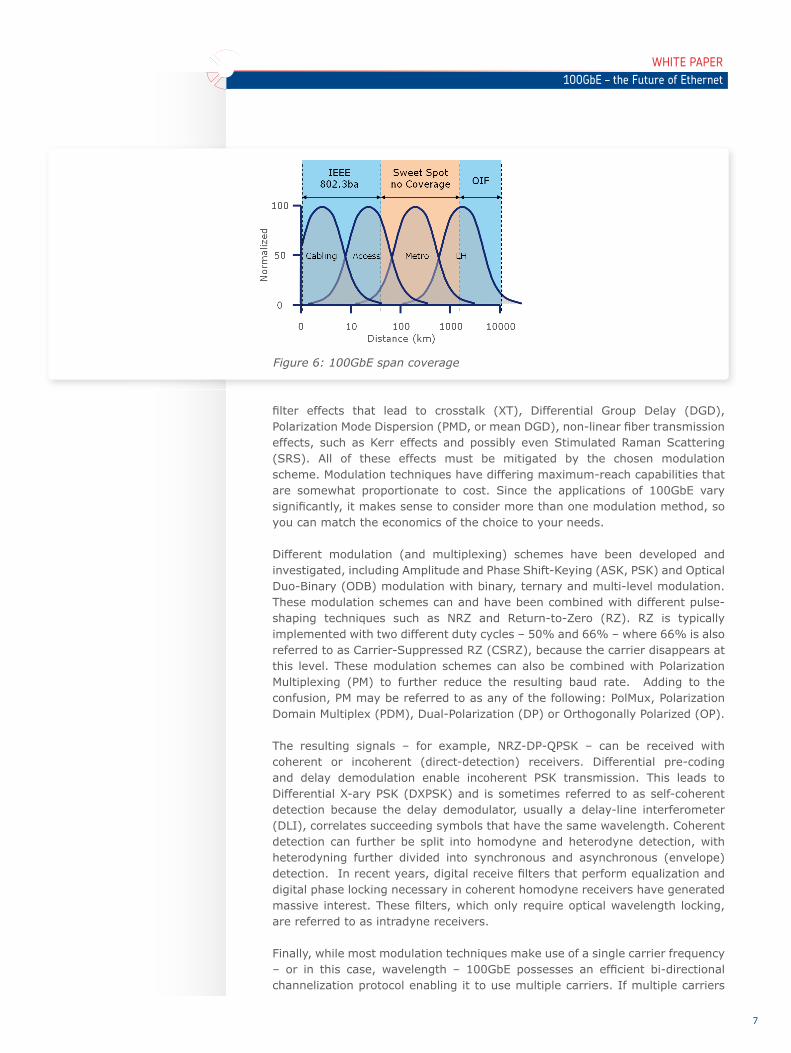
Given 100GbE’s effi cient channelization, coupled with the new emphasis on computing applications, much of the standardization work today is focused on short-reach interconnect. Whether connecting servers to top-of-rack switches, or end-of-row switches to core routers at the corner of the fl oor, these distances are typically less than 10km and sometimes as short as one meter. At the other end of the extreme, networking groups are concentrating their energy on very long reach (100GbE > 1200km). This range holds the greatest promise of compatibility with the span budgets currently used on 10GbE transport links, thus maximizing investment protection. However, 100GbE differs from past Ethernet generations as there appears to be universal demand across all distances. As
10GbE came to fruition, most data traffi c was point-to-point transport of end-user data. Today, as 100GbE emerges, most traffi c travels between the local DC and end users. The local caching of data, cloud computing, social networking, the PDA revolution, as well as a wide host of other trends have all conspired to shorten the average distance a packet travels. Today, there is an urgent and universal need across all distances for 100GbE transport.
Upon closer examination, however, current standards efforts are leaving a sizable gap between 40km and 1200km. If users need to go only 100km, must they really pay for a 1200km link? How about the substantial access and metro networks that are also facing bandwidth exhaustion? Surely they would benefi t from the unique features of 100GbE. With these questions in mind, let us delve deeper into the technology that enables 100GbE.
Modulation Formats
Long-haul 100GbE transport will generally be limited by a combination of accumulated noise (Amplifi ed Spontaneous Emission, or ASE), CD, accumulated
Figure 5: Networking vs. computing growth
Today, there is an urgent and universal need across all distances for 100GbE transport.
WHITE PAPER100GbE – the Future of Ethernet
7
fi lter effects that lead to crosstalk (XT), Differential Group Delay (DGD), Polarization Mode Dispersion (PMD, or mean DGD), non-linear fi ber transmission effects, such as Kerr effects and possibly even Stimulated Raman Scattering (SRS). All of these effects must be mitigated by the chosen modulation scheme. Modulation techniques have differing maximum-reach capabilities that are somewhat proportionate to cost. Since the applications of 100GbE vary signifi cantly, it makes sense to consider more than one modulation method, so you can match the economics of the choice to your needs.
Different modulation (and multiplexing) schemes have been developed and investigated, including Amplitude and Phase Shift-Keying (ASK, PSK) and Optical Duo-Binary (ODB) modulation with binary, ternary and multi-level modulation. These modulation schemes can and have been combined with different pulse-shaping techniques such as NRZ and Return-to-Zero (RZ). RZ is typically implemented with two different duty cycles – 50% and 66% – where 66% is also referred to as Carrier-Suppressed RZ (CSRZ), because the carrier disappears at this level. These modulation schemes can also be combined with Polarization Multiplexing (PM) to further reduce the resulting baud rate. Adding to the confusion, PM may be referred to as any of the following: PolMux, Polarization Domain Multiplex (PDM), Dual-Polarization (DP) or Orthogonally Polarized (OP).
The resulting signals – for example, NRZ-DP-QPSK – can be received with coherent or incoherent (direct-detection) receivers. Differential pre-coding and delay demodulation enable incoherent PSK transmission. This leads to Differential X-ary PSK (DXPSK) and is sometimes referred to as self-coherent detection because the delay demodulator, usually a delay-line interferometer (DLI), correlates succeeding symbols that have the same wavelength. Coherent detection can further be split into homodyne and heterodyne detection, with heterodyning further divided into synchronous and asynchronous (envelope) detection. In recent years, digital receive fi lters that perform equalization and digital phase locking necessary in coherent homodyne receivers have generated massive interest. These fi lters, which only require optical wavelength locking, are referred to as intradyne receivers.
Finally, while most modulation techniques make use of a single carrier frequency – or in this case, wavelength – 100GbE possesses an effi cient bi-directional channelization protocol enabling it to use multiple carriers. If multiple carriers
Figure 6: 100GbE span coverage
WHITE PAPER100GbE – the Future of Ethernet
8
are squeezed into a single wavelength slot in the ITU WDM channel grid, this leads to the concept of inverse multiplexing. If all carriers, then referred to as sub-carriers, are allocated a common WDM slot, this spawns Optical Orthogonal Frequency-Domain Multiplexing (O-OFDM) or Sub-Carrier Multiplexing (SCM) techniques. One special case is to use two carriers, which leads to modulation schemes like NRZ-DC-DP-QPSK.
All of these modulation techniques have advantages and disadvantages, and the most appropriate modulation scheme will depend upon fi ber quality, link length, deployment scenario (for example, upgrade of existing systems with 10G dispersion compensation map or green-fi eld deployment), WDM grid (100GHz or 50GHz), and WDM fi lter technology (for example, AWG fi lters, WSS-based ROADMs). Now, let’s take a closer look at the aforementioned modulation techniques.
100GbE Modulation Schemes
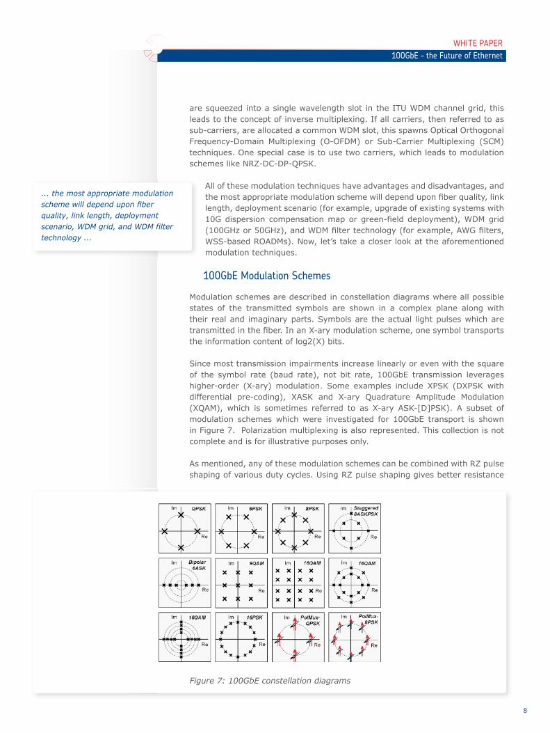
Modulation schemes are described in constellation diagrams where all possible states of the transmitted symbols are shown in a complex plane along with their real and imaginary parts. Symbols are the actual light pulses which are transmitted in the fi ber. In an X-ary modulation scheme, one symbol transports the information content of log2(X) bits.
Since most transmission impairments increase linearly or even with the square of the symbol rate (baud rate), not bit rate, 100GbE transmission leverages higher-order (X-ary) modulation. Some examples include XPSK (DXPSK with differential pre-coding), XASK and X-ary Quadrature Amplitude Modulation (XQAM), which is sometimes referred to as X-ary ASK-[D]PSK). A subset of modulation schemes which were investigated for 100GbE transport is shown in Figure 7. Polarization multiplexing is also represented. This collection is not complete and is for illustrative purposes only.
As mentioned, any of these modulation schemes can be combined with RZ pulse shaping of various duty cycles. Using RZ pulse shaping gives better resistance
... the most appropriate modulation scheme will depend upon fi ber quality, link length, deployment scenario, WDM grid, and WDM fi lter technology ...
Figure 7: 100GbE constellation diagrams

WHITE PAPER100GbE – the Future of Ethernet
9
against non-linear transmission effects, reduces non-linear penalties on the receive-end OSNR and produces slightly better PMD tolerance and OSNR. It requires an additional pulse carver, however, which is yet another external Mach-Zehnder modulator. RZ also increases bandwidth requirements by a factor of two, which in turn decreases spectral effi ciency when compared to NRZ. Figure 8 shows the effect of NRZ and RZ pulse shaping on slowly varying pulse envelopes for OOK and DPSK.
Figure 9 shows the bandwidth allocation for the three different pulse shapes for OOK. NRZ clearly requires the least bandwidth for this modulation type. Similar relationships apply to other modulation schemes.
So, which modulation scheme is best for 100GbE? There is more than one answer. Let’s start with the most popular modulation scheme, which also happens to yield the longest distance.
Long Haul (LH) Transport
Today, most agree that LH 100GbE transport – which will actually run at 112Gbit/s due to added OTH framing and forward error correction (FEC) channel coding – will be best based on coherent, single-carrier, dual-polarization QPSK with a digital intradyne receiver and NRZ pulse shaping (coherent NRZ-DP-QPSK). Though the acronym may be long, this modulation scheme yields high CD and PMD tolerance through the use of a digital-receive fi lter. It also produces high spectral effi ciency in the range of 2
Figure 8: Envelopes of binary NRZ-, 50%-RZ-, and CSRZ-OOK, and NRZ- and 50%-RZ-DPSK
Figure 9: Normalized spectra of NRZ-, CSRZ- and 50%-RZ-OOK
LH 100GbE transport will be best based on coherent, single-carrier, dual-polarization QPSK with a digital intradyne receiver and NRZ pulse shaping.

WHITE PAPER100GbE – the Future of Ethernet
10
(bit/s)/Hz, which allows it to fi t within a 50GHz WDM grid. Drawbacks include complexity and the associated cost of the digital fi lter that must be able to process four A/D-converted bit streams of 28Gbit/s in real time (the capacity to process ~1.1Tbit/s). This fi lter will be a major source of energy consumption in transceivers, and no fi lter components of this type are commercially available today. Figure 10 shows a block diagram of a DP-QPSK system. This diagram also shows the location of additional optional pulse carvers, should RZ-DP-QPSK be the goal.
Since developing the digital receiver remains challenging to say the least, several systems vendors are looking at alternatives, including incoherent NRZ DP-DQPSK and coherent NRZ DC-DP-QPSK with a dual-carrier approach. Neither alternative will attain the lofty performance of coherent intradyne DP-QPSK, due to a mixture of non-linear effects and poorer OSNR. Incoherent DP-DQPSK also requires ultra-fast, reliable polarization controllers, and DC-DP-QPSK cannot make use of upcoming standardized components because this scheme runs at half the baud rate. Figure 11 shows incoherent DP-DQPSK for comparison.
Metropolitan (Metro) Transport
If a variation of coherent NRZ-DP-QPSK provides a solution for LH 100GbE transport and the 802.3ba standard offers suitable short reach options, what should a customer use at access and metro distances? The LH solution strikes an optimal cost/performance balance for LH, but it is not cost-effi cient for regional distances shorter than 600km.
If you relax requirements regarding spectral effi ciency, you can omit polarization multiplexing and employ X-ary ASK or DPSK modulation. D8PSK transmission is one option in this scenario. However, if 8-ary PSK modulation is used for 112Gbit/s signals, it produces a symbol or baud rate of roughly 37 GBd which is not (and likely won’t be) covered by standard commercial components.
To overcome the component problem, upcoming 100GbE components (running at 28 GBd) or standard 40G components (running at 43 GBd or half of 43 GBd) need to be used. One solution is to use 6-ary modulation that produces a baud
Figure 10: Coherent intradyne DP-QPSK transmission system. LPF denotes a low-pass fi lter, PC denotes a passive optical polarization controller, and PBS denotes a polarization beam splitter.

WHITE PAPER100GbE – the Future of Ethernet
11
rate of 112/log2(6)≈43.75 and can be built using standard 40G components. The respective modulation schemes are either D6PSK or bi-polar 6ASK. Bi-polar 6ASK can be realized using a combination of differential phase shift-keying and 3-ary ASK (DPSK-3ASK).
D6PSK and DPSK-3ASK can be combined with RZ pulse shaping for slightly increased OSNR and PMD performance and somewhat lower susceptibility to non-linear transmission effects on the fi ber. DPSK-3ASK has advantages over D6PSK because it only requires a single DLI with a balanced, dual-photo-diode receiver. The lower resulting cost makes it the preferred choice for shorter distances. Figure 12 shows the block diagram of an RZ-DPSK-3ASK transmission system. This system obviously requires signifi cantly fewer components than DP-(D)QPSK, although the remaining components have to run at 44 GBd instead of 28 GBd.
Access Transport
Many applications, in particular in the high-performance data center, remote backup and business continuity areas, will not require maximum distances in excess of 100km. They may not even require the highest spectral effi ciency because often multiple dedicated fi bers are available. Instead, the primary considerations are lowest cost and latency. For these applications, a low-
Figure 11: Incoherent NRZ-DP-DQPSK system. DPC denotes a dynamic polarization controller and R denotes a direct-detection receiver.
Figure 12: Incoherent RZ-DPSK-3ASK transmission system
Many applications, in particular in the high-performance data center, remote backup and business continu-ity areas, will not require maximum distances in excess of 100km.

WHITE PAPER100GbE – the Future of Ethernet
12
complexity, multi-carrier approach that allows reduced electronic processing makes perfect sense. Multiple carriers allow moderate baud rates, and in some cases may even allow FEC to be omitted (and the latency that goes with it).
Two fundamentally different modes of operation for a multi-carrier approach exist. In the fi rst, where all carriers consume individual WDM slots, the concept of an inverse multiplexer may be employed. The advantages of this approach are low complexity and good reach performance. The only disadvantage is the resulting loss of spectral effi ciency.
In the second mode, all carriers fall within a single WDM channel – for example, 100GHz. If the 100GbE is split into 4x28G, spectral effi ciency is increased by a factor of 2.5 when compared to 10G running on the same grid. This scheme can be called SCM or O-OFDM, depending on the subcarrier spacing. O-OFDM can be implemented as a discrete, analog service, or digitally, as it is used in mobile communications (but at much higher bit rates). Digital O-OFDM, currently suffers from the disadvantage of complex digital circuitry. Figure 13 shows the block diagram of a simple four-channel O-OFDM system. Four streams of ODB-coded symbols are modulated onto four sub-carriers. At the receive-end, simple direct-detection receivers can be used. When comparing this approach to the aforementioned modulation schemes, it becomes apparent that fewer components are necessary and cost reduction is possible. Despite the low cost, this modulation scheme can travel distances up to 200km.
With NRZ-ODB coding, a spectral effi ciency of 1 (bit/s)/Hz can be achieved. Thus, this O-OFDM signal fi ts into a single 100GHz WDM slot. This is demonstrated in Figure 14, which shows a spectral scan of the O-OFDM signal. Due to the tight
Figure 13: O-OFDM system with NRZ-ODB coding and simple direct detection
Figure 14: Spectral effi ciency of 4-channel O-OFDM
WHITE PAPER100GbE – the Future of Ethernet
13
sub-carrier spacing, a certain amount of cross-talk is unavoidable and limits the reach to 200km or less. Contrast this with the inverse-multiplexer mode, where the maximum reach can easily extend into the 500km range.
Application optimized 100GbE
100GbE modulation techniques offer a wide range of performance and cost points. If a cost differential is suffi ciently high at 25% or above, this justifi es the use of more than a single, one-size-fi ts-all modulation scheme. An analysis is required which would take transmission performance, spectral effi ciency, cost and latency into account.
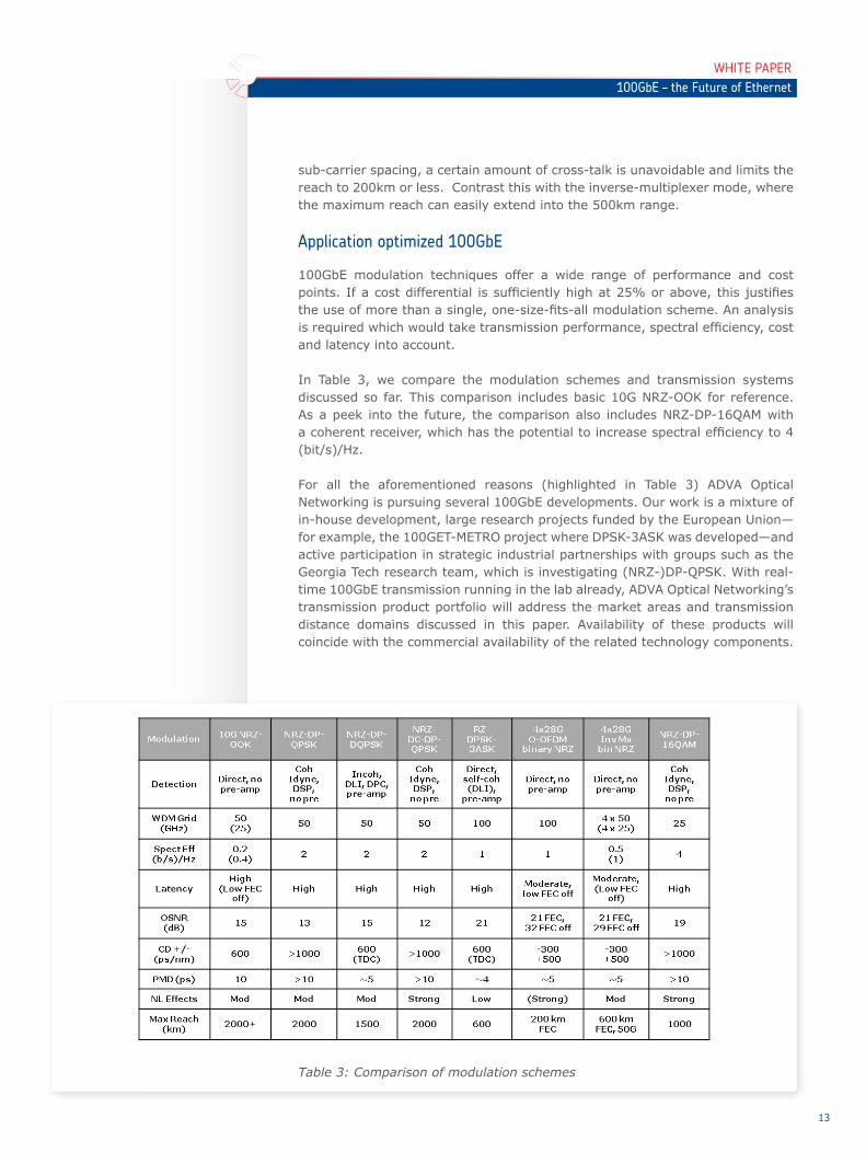
In Table 3, we compare the modulation schemes and transmission systems discussed so far. This comparison includes basic 10G NRZ-OOK for reference. As a peek into the future, the comparison also includes NRZ-DP-16QAM with a coherent receiver, which has the potential to increase spectral effi ciency to 4 (bit/s)/Hz.
For all the aforementioned reasons (highlighted in Table 3) ADVA Optical Networking is pursuing several 100GbE developments. Our work is a mixture of in-house development, large research projects funded by the European Union—for example, the 100GET-METRO project where DPSK-3ASK was developed—and active participation in strategic industrial partnerships with groups such as the Georgia Tech research team, which is investigating (NRZ-)DP-QPSK. With real-time 100GbE transmission running in the lab already, ADVA Optical Networking’s transmission product portfolio will address the market areas and transmission distance domains discussed in this paper. Availability of these products will coincide with the commercial availability of the related technology components.
Table 3: Comparison of modulation schemes

About ADVA Optical Networking
ADVA Optical Networking is a global provider of intelligent telecommunications infrastructure solutions. With software-automated Optical+Ethernet transmission technology, the Company builds the foundation for high-speed, next-generation networks. The Company’s FSP product family adds scalability and intelligence to customers’ networks while removing complexity and cost. Thanks to reliable performance for more than 15 years, the Company has become a trusted partner for more than 250 carriers and 10,000 enterprises across the globe.
Products
FSP 3000ADVA Optical Networking’s scalable optical transport solution is a modular WDM system specifi cally designed to maximize the bandwidth and service fl exibility of access, metro and core networks. The unique optical layer design supports WDM-PON, CWDM and DWDM technology, including 100Gbit/s line speeds with colorless, directionless and contentionless ROADMs. RAYcontrol™, our integrated, industry-leading multi-layer GMPLS control plane, guarantees operational simplicity, even in complex meshed-network topologies. Thanks to OTN, Ethernet and low-latency aggregation, the FSP 3000 represents a highly versatile and cost-effective solution for packet optical transport.
FSP 150ADVA Optical Networking’s family of intelligent Ethernet access products provides devices for Carrier Ethernet service demarcation, extension and aggregation. It supports delivery of intelligent Ethernet services both in-region and out-of-region. Incorporating an MEF-certifi ed UNI and the latest OAM and advanced Etherjack™ demarcation capabilities, the FSP 150 products enable delivery of SLA-based services with full end-to-end assurance. Its comprehensive Syncjack™ technology for timing distribution, monitoring and timing service assurance opens new revenue opportunities from the delivery of synchronization services.
For more information visit us at www.advaoptical.com
ADVA Optical Networking North America, Inc.5755 Peachtree Industrial Blvd.Norcross, Georgia 30092USA
ADVA Optical Networking SECampus Martinsried Fraunhoferstrasse 9 a 82152 Martinsried / Munich Germany
ADVA Optical Networking Singapore Pte. Ltd. 25 International Business Park#05-106 German CentreSingapore 609916
14
Vers
ion
07 / 20
12
WHITE PAPER100GbE – the Future of Ethernet


