WOUND CORES STRIP WOUND CORES STRIP WO - Elna...
16
WOUND CORES STRIP WOUND CORES STRIP W
Transcript of WOUND CORES STRIP WOUND CORES STRIP WO - Elna...
WOUND CORES STRIP WOUND CORES STRIP WO
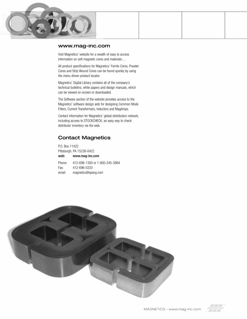
www.mag-inc.com
Visit Magnetics’ website for a wealth of easy to accessinformation on soft magnetic cores and materials…
All product specifications for Magnetics’ Ferrite Cores, PowderCores and Strip Wound Cores can be found quickly by usingthe menu driven product locator.
Magnetics’ Digital Library contains all of the company’stechnical bulletins, white papers and design manuals, whichcan be viewed on-screen or downloaded.
The Software section of the website provides access to theMagnetics’ software design aids for designing Common ModeFilters, Current Transformers, Inductors and MagAmps.
Contact information for Magnetics’ global distribution network,including access to STOCKCHECK, an easy way to checkdistributor inventory via the web.
Contact Magnetics
P.O. Box 11422Pittsburgh, PA 15238-0422web: www.mag-inc.com
Phone: 412-696-1300 or 1-800-245-3984Fax: 412-696-0333email: [email protected]
x
2 MAGNETICS – www.mag-inc.com
MAGNETICS – www.mag-inc.com 3
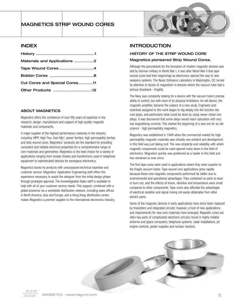
MAGNETICS STRIP WOUND CORES
INDEX
History ................................................1
Materials and Applications ................2
Tape Wound Cores ............................4
Bobbin Cores ....................................8
Cut Cores and Special Cores............11
Other Products ................................12
ABOUT MAGNETICS
Magnetics offers the confidence of over fifty years of expertise in theresearch, design, manufacture and support of high quality magneticmaterials and components.
A major supplier of the highest performance materials in the industryincluding: MPP, High Flux, Kool Mµ®, power ferrites, high permeability ferritesand strip wound cores, Magnetics’ products set the standard for providingconsistent and reliable electrical properties for a comprehensive range ofcore materials and geometries. Magnetics is the best choice for a variety ofapplications ranging from simple chokes and transformers used in telephoneequipment to sophisticated devices for aerospace electronics.
Magnetics backs its products with unsurpassed technical expertise andcustomer service. Magnetics’ Application Engineering staff offers theexperience necessary to assist the designer from the initial design phasethrough prototype approval. The knowledgeable Sales staff is available tohelp with all of your customer service needs. This support, combined with aglobal presence via a worldwide distribution network, including sales officesin North America, Asia and Europe, and a Hong Kong distribution center,makes Magnetics a premier supplier to the international electronics industry.
INTRODUCTION
HISTORY OF THE STRIP WOUND CORE
Magnetics pioneered Strip Wound Cores.
Although the groundwork for the formation of modern magnetic devices waslaid by German military in World War I, it was after World War II that tapewound cores had their beginnings as electronics opened the way to newweapons systems. The Naval Ordnance Laboratory in Washington, DC turnedits attention to facets of magnetism in devices where the vacuum tube had aserious drawback - fragility.
The Navy was constantly looking for a device with the vacuum tube’s preciseability to control, but with none of its physical limitations. An old device, themagnetic amplifier, became the subject of a new study. Engineers andscientists assigned to this work began to dig deeply into the function thecore plays, and particularly what could be done by using newer nickel-ironalloys. It was discovered that some alloys would reach saturation with verylow magnetizing currents. This started the beginning of a new era for an oldscience - high permeability magnetics.
Magnetics was established in 1949 when the commercial market for highpermeability magnetic materials was virtually non-existent and developmentin this field was just taking root. The new simplicity and reliability with whichmagnetic components could be used opened many doors in the field ofelectronics. Magnetics quickly was positioned as a leader in this field andhas remained so ever since.
The first tape cores were used in applications where they were superior tothe fragile vacuum tubes. Tape wound core applications grew rapidlybecause these new magnetic components performed far better due toenvironmental and operational advantages. They contained no parts to wearor burn out; and the effects of shock, vibration and temperature were smallcompared to other components. Tape cores also afforded the advantages of electrical isolation and signal mixing not easily obtainable from otherelectric parts.
Some of the magnetic devices in early applications have since been replacedby transistors and integrated circuits; however, a host of new applicationsand requirements for new core materials have emerged. Magnetic cores areoften key parts of complicated electronic circuitry found in highly reliableairborne and space computers, telephone systems, radar installations, jetengine controls, power supplies and nuclear reactors.
MAGNETICS – www.mag-inc.com4
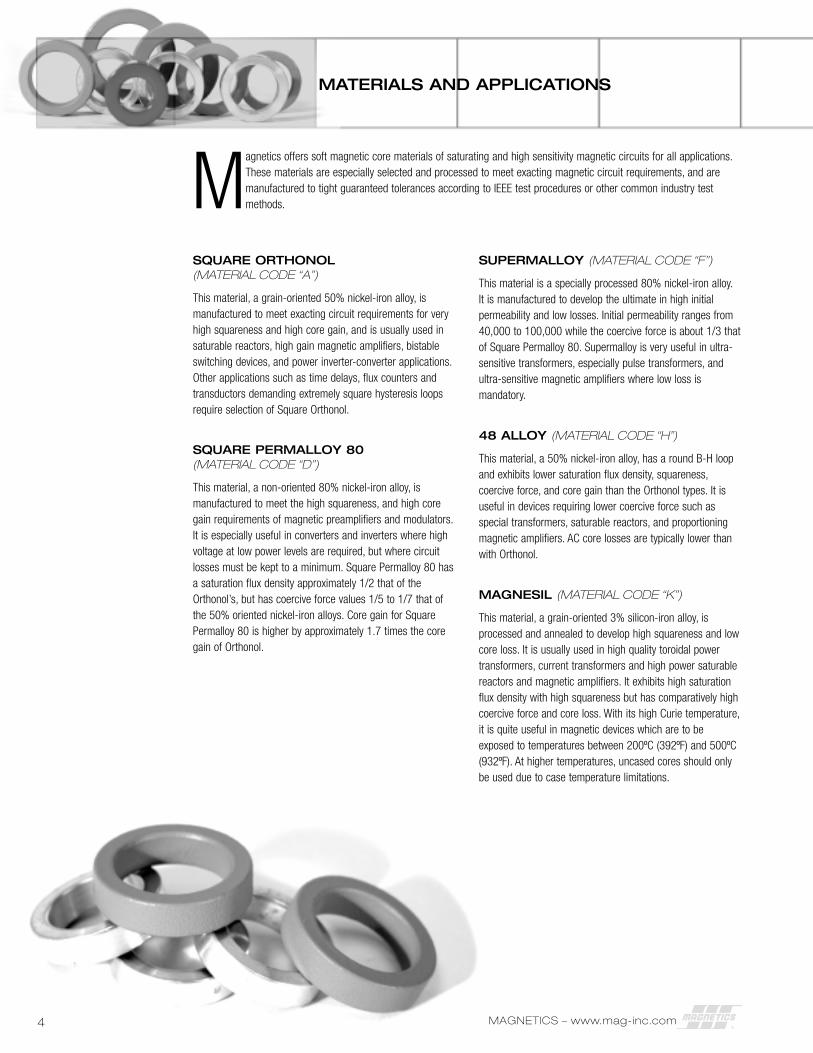
Magnetics offers soft magnetic core materials of saturating and high sensitivity magnetic circuits for all applications.These materials are especially selected and processed to meet exacting magnetic circuit requirements, and aremanufactured to tight guaranteed tolerances according to IEEE test procedures or other common industry testmethods.
SQUARE ORTHONOL(MATERIAL CODE “A”)
This material, a grain-oriented 50% nickel-iron alloy, ismanufactured to meet exacting circuit requirements for veryhigh squareness and high core gain, and is usually used insaturable reactors, high gain magnetic amplifiers, bistableswitching devices, and power inverter-converter applications.Other applications such as time delays, flux counters andtransductors demanding extremely square hysteresis loopsrequire selection of Square Orthonol.
SQUARE PERMALLOY 80(MATERIAL CODE “D”)
This material, a non-oriented 80% nickel-iron alloy, ismanufactured to meet the high squareness, and high coregain requirements of magnetic preamplifiers and modulators.It is especially useful in converters and inverters where highvoltage at low power levels are required, but where circuitlosses must be kept to a minimum. Square Permalloy 80 hasa saturation flux density approximately 1/2 that of theOrthonol’s, but has coercive force values 1/5 to 1/7 that ofthe 50% oriented nickel-iron alloys. Core gain for SquarePermalloy 80 is higher by approximately 1.7 times the coregain of Orthonol.
SUPERMALLOY (MATERIAL CODE “F”)
This material is a specially processed 80% nickel-iron alloy.It is manufactured to develop the ultimate in high initialpermeability and low losses. Initial permeability ranges from40,000 to 100,000 while the coercive force is about 1/3 thatof Square Permalloy 80. Supermalloy is very useful in ultra-sensitive transformers, especially pulse transformers, andultra-sensitive magnetic amplifiers where low loss ismandatory.
48 ALLOY (MATERIAL CODE “H”)
This material, a 50% nickel-iron alloy, has a round B-H loopand exhibits lower saturation flux density, squareness,coercive force, and core gain than the Orthonol types. It isuseful in devices requiring lower coercive force such asspecial transformers, saturable reactors, and proportioningmagnetic amplifiers. AC core losses are typically lower thanwith Orthonol.
MAGNESIL (MATERIAL CODE “K”)
This material, a grain-oriented 3% silicon-iron alloy, isprocessed and annealed to develop high squareness and lowcore loss. It is usually used in high quality toroidal powertransformers, current transformers and high power saturablereactors and magnetic amplifiers. It exhibits high saturationflux density with high squareness but has comparatively highcoercive force and core loss. With its high Curie temperature,it is quite useful in magnetic devices which are to beexposed to temperatures between 200ºC (392ºF) and 500ºC(932ºF). At higher temperatures, uncased cores should onlybe used due to case temperature limitations.
MATERIALS AND APPLICATIONS
5
MATERIALS AND APPLICATIONS
ROUND PERMALLOY 80(MATERIAL CODE “R”)
This material, a non-oriented 80% nickel-iron alloy, isprocessed to develop high initial permeability and lowcoercive force. It has lower squareness and core gain thanthe square type, as these characteristics are sacrificed toproduce the high initial permeability and low coercive forceproperties. Round Permalloy 80 is especially useful indesigning highly sensitive input and inter-stage transformerswhere signals are extremely low and DC currents are notpresent. It is also useful in current transformers where lossesmust be kept to a minimum and high accuracy is anecessity. The initial permeability of this material is usuallybetween 20,000 and 50,000 with coercive force valuesabout 70% that of Square Permalloy 80.
SUPERMENDUR (MATERIAL CODE “S”)
This material, available in small quantity by special order, is ahighly refined 50% cobalt-iron alloy. It is specially processedand annealed to develop high squareness and highsaturation flux density. Supermendur serves well in devicesrequiring extreme miniaturization and high operatingtemperatures. It can be used in the same types ofapplications as Magnesil; however, due to its higher fluxdensity (approximately 21,000 gausses), reduction in coresize and weight may be accomplished. It has the highestCurie temperature of any of the available square loop alloys,so it will find applications in high temperature work.
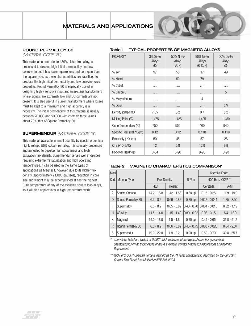
Table 1 TYPICAL PROPERTIES OF MAGNETIC ALLOYS
PROPERTY 3% Si-Fe 50% Ni-Fe 80% Ni-Fe 50% Co-FeAlloys Alloys Alloys Alloys
(K) (A, H) (R, D, F) (S)
% Iron 97 50 17 49
% Nickel …. 50 79 ….
% Cobalt …. …. …. ….
% Silicon 3 …. …. …. 5
% Molybdenum …. …. 4 ….
% Other …. …. …. 2 V
Density (gms/cm3) 7.65 8.2 8.7 8.2
Melting Point (ºC) 1,475 1,425 1,425 1,480
Curie Temperature (ºC) 750 500 460 940
Specific Heat (Cal./ºCgm) 0.12 0.12 0.118 0.118
Resistivity (µΩ-cm) 50 45 57 26
CTE (x10-6/ºC) 12 5.8 12.9 9.9
Rockwell Hardness B-84 B-90 B-95 B-98
Mat’l Coercive Force
Code Material Type Flux Density Br/Bm 400 Hertz CCFR **
(kG) (Teslas) Oersteds A/M
Table 2 MAGNETIC CHARACTERISTICS COMPARISON*
A Square Orthonol 14.2 - 15.8 1.42 - 1.58 0.88 up 0.15 - 0.25 11.9 - 19.9
D Square Permalloy 80 6.6 - 8.2 0.66 - 0.82 0.80 up 0.022 - 0.044 1.75 - 3.50
F Supermalloy 6.5 - 8.2 0.65 - 0.82 0.40 - 0.70 0.004 - 0.015 0.32 - 1.19
H 48 Alloy 11.5 - 14.0 1.15 - 1.40 0.80 - 0.92 0.08 - 0.15 6.4 - 12.0
K Magnesil 15.0 - 18.0 1.5 - 1.8 0.85 up 0.45 - 0.65 35.8 - 51.7
R Round Permalloy 80 6.6 - 8.2 0.66 - 0.82 0.45 - 0.75 0.008 - 0.026 0.64 - 2.07
S Supermendur 19.0 - 22.0 1.9 - 2.2 0.90 up 0.50 - 0.70 39.8 - 55.7
* The values listed are typical of 0.002" thick materials of the types shown. For guaranteedcharacteristics on all thicknesses of alloys available, contact Magnetics Applications EngineeringDepartment.
** 400 Hertz CCFR Coercive Force is defined as the H1 reset characteristic described by the ConstantCurrent Flux Reset Test Method in IEEE Std. #393.
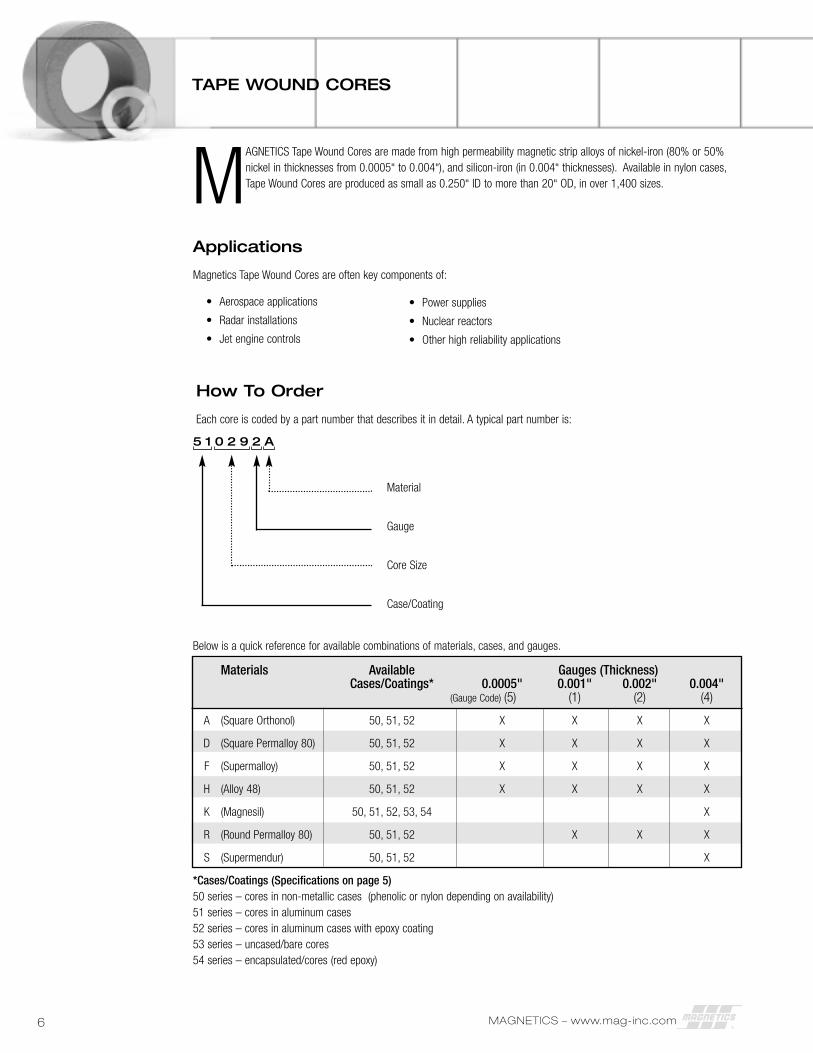
Below is a quick reference for available combinations of materials, cases, and gauges.
Materials Available Gauges (Thickness)Cases/Coatings* 0.0005" 0.001" 0.002" 0.004"
(Gauge Code) (5) (1) (2) (4)
A (Square Orthonol) 50, 51, 52 X X X X
D (Square Permalloy 80) 50, 51, 52 X X X X
F (Supermalloy) 50, 51, 52 X X X X
H (Alloy 48) 50, 51, 52 X X X X
K (Magnesil) 50, 51, 52, 53, 54 X
R (Round Permalloy 80) 50, 51, 52 X X X
S (Supermendur) 50, 51, 52 X
*Cases/Coatings (Specifications on page 5)50 series – cores in non-metallic cases (phenolic or nylon depending on availability)51 series – cores in aluminum cases52 series – cores in aluminum cases with epoxy coating53 series – uncased/bare cores54 series – encapsulated/cores (red epoxy)
MAGNETICS – www.mag-inc.com6
TAPE WOUND CORES
Applications
Magnetics Tape Wound Cores are often key components of:
• Aerospace applications
• Radar installations
• Jet engine controls
MAGNETICS Tape Wound Cores are made from high permeability magnetic strip alloys of nickel-iron (80% or 50%nickel in thicknesses from 0.0005" to 0.004"), and silicon-iron (in 0.004" thicknesses). Available in nylon cases,Tape Wound Cores are produced as small as 0.250" ID to more than 20" OD, in over 1,400 sizes.
How To Order
Each core is coded by a part number that describes it in detail. A typical part number is:
Material
Gauge
Core Size
Case/Coating
5 1 0 2 9 2 A
• Power supplies
• Nuclear reactors
• Other high reliability applications
7
CORE CASE SELECTION
NON-METALLIC CASES (CASE/COATING CODE “50”)
For superior electrical properties, improved wearing qualities,and high strength, non-metallic cases are widely used asprotection for the core material against winding stresses andpressures. Both phenolic and nylon types meet a minimum2000 volt breakdown requirement. The glass-filled nylon types can withstand temperatures to 200ºC (392ºF) without softening, while the phenolic materials will withstandtemperatures up to 125ºC (257ºF).
ALUMINUM CASES(CASE/COATING CODE “51”)
Aluminum core cases have great structural strength. A glassepoxy insert, to which the aluminum case is mechanicallybonded, forms an airtight seal. These core cases willwithstand temperatures to 200ºC (392ºF), a critical factor indesigning for extreme environmental conditions. Also, thestrong aluminum construction will prevent any distortion of thecore case, thus preserving the guaranteed magneticproperties of the core within.
ALUMINUM CASE WITH GVB EPOXY PAINT(CASE/COATING CODE “52”)
This case is the same basic construction as the aluminumbox, but in addition it has a thin, epoxy-type, protective coatingsurrounding the case. This finish adds no more than 0.0015"to the OD, subtracts no more than 0.015" from the ID, noradds more than 0.020" to the height.
GVB epoxy paint finish offers a guaranteed minimum voltagebreakdown of 1000 volts from wire to case. This coating willwithstand temperatures as high as 200ºC (392ºF) and as lowas -65ºC (-85ºF) with an operating life of 20,000 hours.
UNCASED/BARE CORES(CASE/COATING CODE “53”)
Because of the extreme sensitivity of nickel-iron cores towinding stresses and pressures, such cores are not availablein an uncased state. Magnesil cores are not as susceptible tothese pressures and are available without cases.
Uncased cores offer a maximum window area. They also offera slightly smaller package and lower cost where slightdeterioration of properties after winding and potting can betolerated.
ENCAPSULATED (RED EPOXY) CORES(CASE/COATING CODE “54”)
Magnesil cores are available in encapsulated form. Thisprotection is a tough, hard epoxy which adheres rigidly to thecore, allowing the winder to wind directly over the core withoutprior taping. A smooth radius prevents wire insulation frombeing scraped.
Encapsulated cores have a guaranteed minimum voltagebreakdown of 1000 volts from core to winding. Thetemperature rating of this finish is 125ºC (257ºF) in free air.
MAGNETICS – www.mag-inc.com8
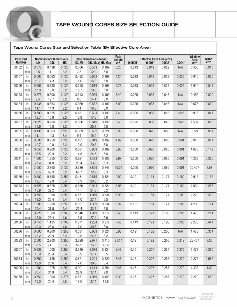
TAPE WOUND CORES SIZE SELECTION GUIDE
Tape Wound Cores Size and Selection Table (By Effective Core Area)
50402 in. 0.375 0.438 0.125 0.306 0.509 0.199 3.25 0.013 0.019 0.022 N/A 0.456 0.010mm. 9.5 11.1 3.2 7.8 12.9 5.0
50107 in. 0.500 0.563 0.125 0.432 0.632 0.199 4.24 0.013 0.019 0.022 0.023 0.916 0.020mm. 12.7 14.3 3.2 11.0 16.0 5.0
50356 in. 0.687 0.750 0.125 0.618 0.819 0.197 5.73 0.013 0.019 0.022 0.023 1.914 0.041mm. 17.0 19.0 3.2 15.7 20.8 5.0
50153 in. 0.375 0.500 0.125 0.313 0.569 0.199 3.49 0.025 0.038 0.043 N/A 0.456 0.020mm. 9.5 12.7 3.2 8.0 14.4 5.0
50154 in. 0.438 0.563 0.125 0.369 0.632 0.199 3.99 0.025 0.038 0.043 N/A 0.673 0.030mm. 11.1 14.3 3.2 9.4 16.0 5.0
50056 in. 0.500 0.625 0.125 0.431 0.694 0.199 4.49 0.025 0.038 0.043 0.045 0.916 0.041mm. 12.7 15.9 3.2 10.9 17.6 5.0
50057 in. 0.625 0.750 0.125 0.556 0.819 0.199 5.48 0.025 0.038 0.043 0.045 1.534 0.066mm. 15.9 19.0 3.2 14.1 20.8 5.0
50155 in. 0.438 0.563 0.250 0.369 0.632 0.324 3.99 0.050 0.076 0.086 N/A 0.724 0.061mm. 11.1 14.3 6.4 9.4 16.0 8.2
50000 in. 0.500 0.750 0.125 0.431 0.819 0.199 4.99 0.050 0.076 0.086 0.091 0.916 0.081mm. 12.7 19.0 3.2 10.9 20.8 5.0
50002 in. 0.650 0.900 0.125 0.581 0.969 0.199 5.98 0.050 0.076 0.086 0.091 1.676 0.142mm. 16.5 22.9 3.2 14.8 24.6 5.0
50011 in. 1.000 1.250 0.125 0.921 1.329 0.209 8.97 0.050 0.076 0.086 0.091 4.238 0.365mm. 25.4 31.8 3.2 23.4 33.8 5.3
50748 in. 2.500 2.750 0.125 2.389 2.869 0.247 20.94 0.050 0.076 0.086 0.091 29.407 2.53mm. 63.5 69.9 3.2 60.7 72.9 6.3
50176 in. 0.500 0.750 0.250 0.431 0.819 0.324 4.99 0.101 0.151 0.171 0.182 0.916 0.157mm. 12.7 19.0 6.4 10.9 20.8 8.2
50033 in. 0.625 0.875 0.250 0.556 0.944 0.324 5.98 0.101 0.151 0.171 0.182 1.534 0.263mm. 15.9 22.2 6.4 14.1 24.0 8.2
50061 in. 0.750 1.000 0.250 0.671 1.079 0.334 6.98 0.101 0.151 0.171 0.182 2.273 0.390mm. 19.0 25.4 6.4 17.0 27.4 8.5
50004 in. 1.000 1.250 0.250 0.921 1.329 0.334 8.97 0.101 0.151 0.171 0.182 4.238 0.724mm. 25.4 31.8 6.4 23.4 33.8 8.5
50076 in. 0.625 1.000 0.188 0.546 1.079 0.272 6.48 0.113 0.171 0.193 0.205 1.478 0.284mm. 15.9 25.4 4.8 13.9 27.4 6.9
50106 in. 0.750 1.125 0.188 0.671 1.204 0.272 7.48 0.113 0.171 0.193 0.205 2.273 0.441mm. 19.0 28.6 4.8 17.0 30.6 6.9
50296 in. 0.600 0.900 0.250 0.531 0.969 0.324 5.98 0.121 0.182 0.206 N/A 1.478 0.304mm. 15.2 22.9 6.4 13.5 24.6 8.2
50323 in. 2.500 2.800 0.250 2.329 2.971 0.410 21.14 0.121 0.182 0.206 0.218 29.407 6.06mm. 63.5 71.1 6.4 59.2 75.5 10.4
50007 in. 0.625 1.000 0.250 0.546 1.079 0.334 6.48 0.151 0.227 0.257 0.272 1.478 0.380mm. 15.9 25.4 6.4 13.9 27.4 8.5
50084 in. 0.750 1.125 0.250 0.671 1.204 0.329 7.48 0.151 0.227 0.257 0.272 2.273 0.582mm. 19.0 28.6 6.4 17.0 30.6 8.4
50029 in. 1.000 1.375 0.250 0.901 1.474 0.354 9.47 0.151 0.227 0.257 0.272 4.438 1.09mm. 25.4 34.9 6.4 22.9 37.4 9.0
50168 in. 0.750 1.000 0.375 0.671 1.079 0.459 6.98 0.151 0.227 0.257 0.272 2.273 0.582mm. 19.0 25.4 9.5 17.0 27.4 11.6
Core PartNumber
Nominal Core DimensionsI.D. O.D. HT.
Case Dimensions (Nylon)I.D. Min O.D. Max HT. Max
Effective Core Area (cm2)0.0005" 0.001" 0.002" 0.004"
PathLength
cm
WindowAreacm2
WaAccm4
MAGNETICS – www.mag-inc.com 9
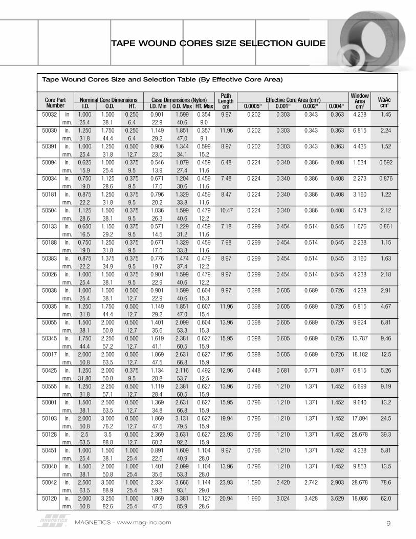
Tape Wound Cores Size and Selection Table (By Effective Core Area)
50032 in 1.000 1.500 0.250 0.901 1.599 0.354 9.97 0.202 0.303 0.343 0.363 4.238 1.45mm. 25.4 38.1 6.4 22.9 40.6 9.0
50030 in. 1.250 1.750 0.250 1.149 1.851 0.357 11.96 0.202 0.303 0.343 0.363 6.815 2.24mm. 31.8 44.4 6.4 29.2 47.0 9.1
50391 in. 1.000 1.250 0.500 0.906 1.344 0.599 8.97 0.202 0.303 0.343 0.363 4.435 1.52mm. 25.4 31.8 12.7 23.0 34.1 15.2
50094 in. 0.625 1.000 0.375 0.546 1.079 0.459 6.48 0.224 0.340 0.386 0.408 1.534 0.592mm. 15.9 25.4 9.5 13.9 27.4 11.6
50034 in. 0.750 1.125 0.375 0.671 1.204 0.459 7.48 0.224 0.340 0.386 0.408 2.273 0.876mm. 19.0 28.6 9.5 17.0 30.6 11.6
50181 in. 0.875 1.250 0.375 0.796 1.329 0.459 8.47 0.224 0.340 0.386 0.408 3.160 1.22mm. 22.2 31.8 9.5 20.2 33.8 11.6
50504 in. 1.125 1.500 0.375 1.036 1.599 0.479 10.47 0.224 0.340 0.386 0.408 5.478 2.12mm. 28.6 38.1 9.5 26.3 40.6 12.2
50133 in. 0.650 1.150 0.375 0.571 1.229 0.459 7.18 0.299 0.454 0.514 0.545 1.676 0.861mm. 16.5 29.2 9.5 14.5 31.2 11.6
50188 in. 0.750 1.250 0.375 0.671 1.329 0.459 7.98 0.299 0.454 0.514 0.545 2.238 1.15mm. 19.0 31.8 9.5 17.0 33.8 11.6
50383 in. 0.875 1.375 0.375 0.776 1.474 0.479 8.97 0.299 0.454 0.514 0.545 3.160 1.63mm. 22.2 34.9 9.5 19.7 37.4 12.2
50026 in. 1.000 1.500 0.375 0.901 1.599 0.479 9.97 0.299 0.454 0.514 0.545 4.238 2.18mm. 25.4 38.1 9.5 22.9 40.6 12.2
50038 in. 1.000 1.500 0.500 0.901 1.599 0.604 9.97 0.398 0.605 0.689 0.726 4.238 2.91mm. 25.4 38.1 12.7 22.9 40.6 15.3
50035 in. 1.250 1.750 0.500 1.149 1.851 0.607 11.96 0.398 0.605 0.689 0.726 6.815 4.67mm. 31.8 44.4 12.7 29.2 47.0 15.4
50055 in. 1.500 2.000 0.500 1.401 2.099 0.604 13.96 0.398 0.605 0.689 0.726 9.924 6.81mm. 38.1 50.8 12.7 35.6 53.3 15.3
50345 in. 1.750 2.250 0.500 1.619 2.381 0.627 15.95 0.398 0.605 0.689 0.726 13.787 9.46mm. 44.4 57.2 12.7 41.1 60.5 15.9
50017 in. 2.000 2.500 0.500 1.869 2.631 0.627 17.95 0.398 0.605 0.689 0.726 18.182 12.5mm. 50.8 63.5 12.7 47.5 66.8 15.9
50425 in. 1.250 2.000 0.375 1.134 2.116 0.492 12.96 0.448 0.681 0.771 0.817 6.815 5.26mm. 31.80 50.8 9.5 28.8 53.7 12.5
50555 in. 1.250 2.250 0.500 1.119 2.381 0.627 13.96 0.796 1.210 1.371 1.452 6.699 9.19mm. 31.8 57.1 12.7 28.4 60.5 15.9
50001 in. 1.500 2.500 0.500 1.369 2.631 0.627 15.95 0.796 1.210 1.371 1.452 9.640 13.2mm. 38.1 63.5 12.7 34.8 66.8 15.9
50103 in. 2.000 3.000 0.500 1.869 3.131 0.627 19.94 0.796 1.210 1.371 1.452 17.894 24.5mm. 50.8 76.2 12.7 47.5 79.5 15.9
50128 in. 2.5 3.5 0.500 2.369 3.631 0.627 23.93 0.796 1.210 1.371 1.452 28.678 39.3mm. 63.5 88.8 12.7 60.2 92.2 15.9
50451 in. 1.000 1.500 1.000 0.891 1.609 1.104 9.97 0.796 1.210 1.371 1.452 4.238 5.81mm. 25.4 38.1 25.4 22.6 40.9 28.0
50040 in. 1.500 2.000 1.000 1.401 2.099 1.104 13.96 0.796 1.210 1.371 1.452 9.853 13.5mm. 38.1 50.8 25.4 35.6 53.3 28.0
50042 in. 2.500 3.500 1.000 2.334 3.666 1.144 23.93 1.590 2.420 2.742 2.903 28.678 78.6mm. 63.5 88.9 25.4 59.3 93.1 29.0
50120 in. 2.000 3.250 1.000 1.869 3.381 1.127 20.94 1.990 3.024 3.428 3.629 18.086 62.0mm. 50.8 82.6 25.4 47.5 85.9 28.6
Core PartNumber
Nominal Core DimensionsI.D. O.D. HT.
Case Dimensions (Nylon)I.D. Min O.D. Max HT. Max
PathLength
cm
WindowAreacm2
WaAccm4
Effective Core Area (cm2)0.0005" 0.001" 0.002" 0.004"
TAPE WOUND CORES SIZE SELECTION GUIDE
MAGNETICS – www.mag-inc.com10
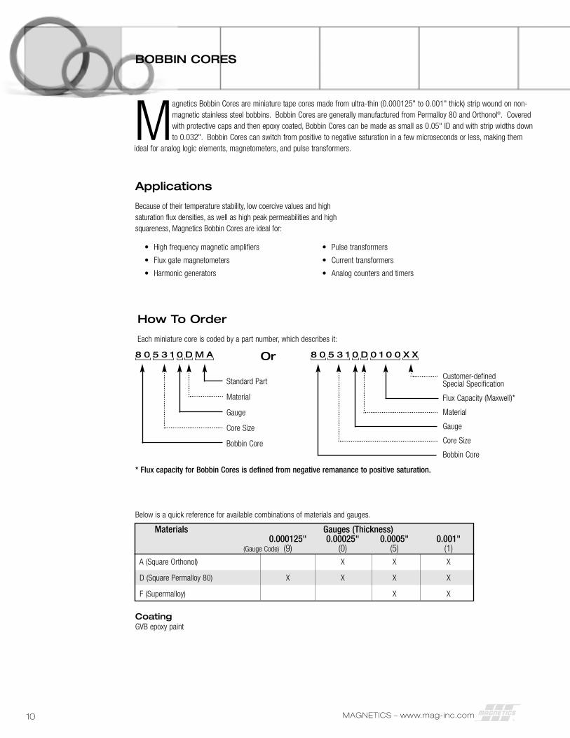
* Flux capacity for Bobbin Cores is defined from negative remanance to positive saturation.
Below is a quick reference for available combinations of materials and gauges.
Materials Gauges (Thickness)0.000125" 0.00025" 0.0005" 0.001"
(Gauge Code) (9) (0) (5) (1)
A (Square Orthonol) X X X
D (Square Permalloy 80) X X X X
F (Supermalloy) X X
CoatingGVB epoxy paint
Applications
Because of their temperature stability, low coercive values and highsaturation flux densities, as well as high peak permeabilities and highsquareness, Magnetics Bobbin Cores are ideal for:
• High frequency magnetic amplifiers
• Flux gate magnetometers
• Harmonic generators
How To Order
Each miniature core is coded by a part number, which describes it:
Standard Part
Material
Gauge
Core Size
Bobbin Core
8 0 5 3 1 0 D M A
Customer-defined Special Specification
Flux Capacity (Maxwell)*
Material
Gauge
Core Size
Bobbin Core
8 0 5 3 1 0 D 0 1 0 0 X X
BOBBIN CORES
Magnetics Bobbin Cores are miniature tape cores made from ultra-thin (0.000125" to 0.001" thick) strip wound on non-magnetic stainless steel bobbins. Bobbin Cores are generally manufactured from Permalloy 80 and Orthonol®. Coveredwith protective caps and then epoxy coated, Bobbin Cores can be made as small as 0.05" ID and with strip widths downto 0.032". Bobbin Cores can switch from positive to negative saturation in a few microseconds or less, making them
ideal for analog logic elements, magnetometers, and pulse transformers.
Or
• Pulse transformers
• Current transformers
• Analog counters and timers
MAGNETICS – www.mag-inc.com 11
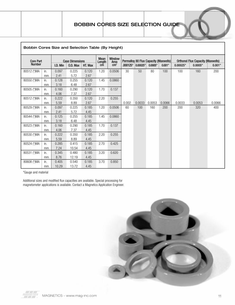
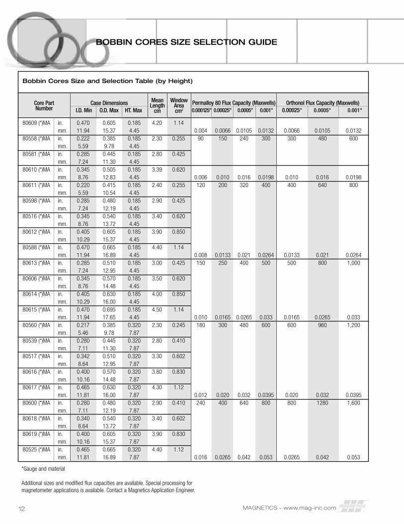
BOBBIN CORES SIZE SELECTION GUIDE
Bobbin Cores Size and Selection Table (By Height)
80512 (*)MA in. 0.097 0.225 0.120 1.20 0.0506 30 50 80 100 100 160 200mm. 2.41 5.72 2.67
80550 (*)MA in. 0.128 0.255 0.120 1.45 0.0860mm. 3.18 6.48 2.67
80505 (*)MA in. 0.160 0.290 0.120 1.70 0.137mm. 4.06 7.37 2.67
80512 (*)MA in. 0.222 0.350 0.120 2.20 0.255mm. 5.59 8.89 2.67 0.002 0.0033 0.0053 0.0066 0.0033 0.0053 0.0066
80529 (*)MA in. 0.097 0.225 0.185 1.20 0.0506 60 100 160 200 200 320 400mm. 2.41 5.72 4.45
80544 (*)MA in. 0.125 0.255 0.185 1.45 0.0860mm. 3.18 6.48 4.45
80523 (*)MA in. 0.160 0.290 0.185 1.70 0.137mm. 4.06 7.37 4.45
80530 (*)MA in. 0.222 0.350 0.185 2.20 0.255mm. 5.59 8.89 4.45
80524 (*)MA in. 0.285 0.415 0.185 2.70 0.425mm. 7.24 10.54 4.45
80531 (*)MA in. 0.345 0.480 0.185 3.20 0.620mm. 8.76 12.19 4.45
80608 (*)MA in. 0.405 0.540 0.185 3.70 0.850mm. 10.29 13.72 4.45
Core PartNumber
Case DimensionsI.D. Min O.D. Max HT. Max
Permalloy 80 Flux Capacity (Maxwells).000125" 0.00025" 0.0005" 0.001"
Orthonol Flux Capacity (Maxwells)0.00025" 0.0005" 0.001"
MeanLength
cm
WindowAreacm2
*Gauge and material
Additional sizes and modified flux capacities are available. Special processing formagnetometer applications is available. Contact a Magnetics Application Engineer.
MAGNETICS – www.mag-inc.com12
BOBBIN CORES SIZE SELECTION GUIDE
Bobbin Cores Size and Selection Table (by Height)
80609 (*)MA in. 0.470 0.605 0.185 4.20 1.14mm. 11.94 15.37 4.45 0.004 0.0066 0.0105 0.0132 0.0066 0.0105 0.0132
80558 (*)MA in. 0.222 0.385 0.185 2.30 0.255 90 150 240 300 300 480 600mm. 5.59 9.78 4.45
80581 (*)MA in. 0.285 0.445 0.185 2.80 0.425mm. 7.24 11.30 4.45
80610 (*)MA in. 0.345 0.505 0.185 3.39 0.620mm. 8.76 12.83 4.45 0.006 0.010 0.016 0.0198 0.010 0.016 0.0198
80611 (*)MA in. 0.220 0.415 0.185 2.40 0.255 120 200 320 400 400 640 800mm. 5.59 10.54 4.45
80598 (*)MA in. 0.285 0.480 0.185 2.90 0.425mm. 7.24 12.19 4.45
80516 (*)MA in. 0.345 0.540 0.185 3.40 0.620mm. 8.76 13.72 4.45
80612 (*)MA in. 0.405 0.605 0.185 3.90 0.850mm. 10.29 15.37 4.45
80588 (*)MA in. 0.470 0.665 0.185 4.40 1.14mm. 11.94 16.89 4.45 0.008 0.0133 0.021 0.0264 0.0133 0.021 0.0264
80613 (*)MA in. 0.285 0.510 0.185 3.00 0.425 150 250 400 500 500 800 1,000mm. 7.24 12.95 4.45
80606 (*)MA in. 0.345 0.570 0.185 3.50 0.620mm. 8.76 14.48 4.45
80614 (*)MA in. 0.405 0.630 0.185 4.00 0.850mm. 10.29 16.00 4.45
80615 (*)MA in. 0.470 0.695 0.185 4.50 1.14mm. 11.94 17.65 4.45 0.010 0.0165 0.0265 0.033 0.0165 0.0265 0.033
80560 (*)MA in. 0.217 0.385 0.320 2.30 0.245 180 300 480 600 600 960 1,200mm. 5.46 9.78 7.87
80539 (*)MA in. 0.280 0.445 0.320 2.80 0.410mm. 7.11 11.30 7.87
80517 (*)MA in. 0.342 0.510 0.320 3.30 0.602mm. 8.64 12.95 7.87
80616 (*)MA in. 0.400 0.570 0.320 3.80 0.830mm. 10.16 14.48 7.87
80617 (*)MA in. 0.465 0.630 0.320 4.30 1.12mm. 11.81 16.00 7.87 0.012 0.020 0.032 0.0395 0.020 0.032 0.0395
80600 (*)MA in. 0.280 0.480 0.320 2.90 0.410 240 400 640 800 800 1280 1,600mm. 7.11 12.19 7.87
80618 (*)MA in. 0.340 0.540 0.320 3.40 0.602mm. 8.64 13.72 7.87
80619 (*)MA in. 0.400 0.605 0.320 3.90 0.830mm. 10.16 15.37 7.87
80525 (*)MA in. 0.465 0.665 0.320 4.40 1.12mm. 11.81 16.89 7.87 0.016 0.0265 0.042 0.053 0.0265 0.042 0.053
Core PartNumber
Case DimensionsI.D. Min O.D. Max HT. Max
Permalloy 80 Flux Capacity (Maxwells)0.000125" 0.00025" 0.0005" 0.001"
Orthonol Flux Capacity (Maxwells)0.00025" 0.0005" 0.001"
MeanLength
cm
WindowAreacm2
*Gauge and material
Additional sizes and modified flux capacities are available. Special processing formagnetometer applications is available. Contact a Magnetics Application Engineer.
MAGNETICS – www.mag-inc.com 13
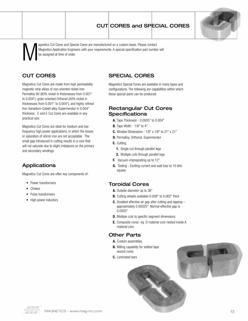
CUT CORES and SPECIAL CORES
Magnetics Cut Cores and Special Cores are manufactured on a custom basis. Please contactMagnetics Application Engineers with your requirements. A special specification part number willbe assigned at time of order.
SPECIAL CORES
Magnetics Special Cores are available in many types andconfigurations. The following are capabilities within whichthese special parts can be produced.
Rectangular Cut CoresSpecifications
A. Tape Thickness - 0.0005" to 0.004"
B. Tape Width - 1/8" to 4"
C. Window Dimensions - 1/8" x 1/8" to 21" x 21"
D. Permalloy, Orthonol, Supermendur
E. Cutting
1. Single cut through parallel legs
2. Multiple cuts through parallel legs
F. Vacuum-impregnating up to 12".
G. Testing - Exciting current and watt loss to 10 kHz-square.
Toroidal CoresA. Outside diameter-up to 36"
B. Cutting wheels available-0.008" to 0.062" thick
C. Smallest effective air gap after cutting and lapping –approximately 0.00025". Normal effective gap is0.0005"
D. Multiple cuts to specific segment dimensions
E. Composite cores - eg. D material core nested inside Amaterial core
Other PartsA. Custom assemblies
B. Milling capability for slotted tape wound cores
C. Laminated bars
CUT CORES
Magnetics Cut Cores are made from high permeabilitymagnetic strip alloys of non-oriented nickel-ironPermalloy 80 (80% nickel in thicknesses from 0.001"to 0.004"), grain-oriented Orthonol (50% nickel inthicknesses from 0.001" to 0.004"), and highly refinedIron-Vanadium-Cobalt alloy Supermendur in 0.004"thickness. C and E Cut Cores are available in anypractical size.
Magnetics Cut Cores are ideal for medium and lowfrequency high power applications, in which the lossesor saturation of silicon iron are not acceptable. Thesmall gap introduced in cutting results in a core thatwill not saturate due to slight imbalance on the primaryand secondary windings.
Applications
Magnetics Cut Cores are often key components of:
• Power transformers
• Chokes
• Pulse transformers
• High power inductors
MAGNETICS – www.mag-inc.com14
MPP, HIGH FLUX & KOOL Mµ®
POWDER CORES
Molypermalloy Powder Cores (MPP) are available in tenpermeabilities of 14 through 550, and have guaranteed inductancelimits of ±8%. Insulation on the core is a high dielectric strengthfinish not affected by normal potting compounds and waxes.Twenty-nine sizes include IDs from 0.070" to 1.900" and ODsfrom 0.14" to 3.10". Standard cores include either temperaturestabilized (as wide as -65°C to +125°C) or unstabilized.
High Flux Powder Cores have a higher energy storage capacitythan MPP cores and are available in six permeabilities from 14through 160. Kool Mµ‚ Powder Cores also have a high energystorage capacity, but are more economical than High Flux or MPPcores, and are available in five permeabilities from 26 through125. Both types come in sizes identical to MPP cores. Kool Mµcores are also available in E shapes, U shapes and blocks.
Powder Cores are excellent as low loss inductors for switch modepower supplies, switching regulators, and noise filters. Most coretypes can be shipped immediately from stock.
MPP THINZ™‚ are extremely low height (<1 mm) self shieldedpower inductor cores, allowing finished inductor heights in the 1.5mm to 2 mm range. THINZ come in five sizes with ODs rangingfrom 0.120" through 0.310" and four permeabilities, 125µ, 160µ,200µ, and 250µ.
For further information, view Powder Cores Design Manual andCatalog at www.mag-inc.com.
Applications: Inductors for High Q, Low Loss Filter Circuits,Loading Coils, Transformers, Chokes, and Inductors
FERRITE CORES
Ferrite Cores are manufactured for a wide variety of applications.Magnetics has developed and produces the leading MnZn ferritematerials for power transformers, power inductors, widebandtransformers, common mode chokes, and many other applications.In addition to offering the leading materials, other advantages offerrites from Magnetics include: the full range of standard planar Eand I Cores; rapid prototyping capability for new development; thewidest range of toroid sizes in power and high permeabilitymaterials; standard gapping to precise inductance or mechanicaldimension; wide range of coil former and assembly hardwareavailable; and superior toroid coatings available in several options.
POWER MATERIALS
Three low loss materials are engineered for optimum frequencyand temperature performance in power applications. Magnetics’materials provide superior saturation, high temperatureperformance, low losses, product consistency.
SHAPES: E cores, Planar E cores, ETD, EC, U cores, I cores, PQ,Planar PQ, RM, Toroids (2mm to 86mm), Pot cores, RS (round-slab), DS (double slab), EP, Special shapes
Applications: Telecomm Power Supplies, Computer PowerSupplies, Commercial Power Supplies, Consumer Power Supplies,Automotive, DC-DC Converters, Telecomm Data Interfaces,Impedance Matching Transformers, Handheld Devices, High PowerControl (gate drive), Computer Servers, Distributed Power (DC-DC),EMI Filters, Aerospace, Medical.
HIGH PERMEABILITY MATERIALS
Three high permeability materials (5,000µ, 10,000µ and15,000µ) are engineered for optimum frequency and impedanceperformance in signal, choke and filter applications. Magnetics’materials provide superior loss factor, frequency response,temperature performance, and product consistency.
SHAPES: Toroids (2 mm to 86 mm), E cores, U cores, RM, Potcores, RS (round-slab), DS (double slab), EP, Special shapes
Applications: Common Mode Chokes, EMI Filters, Other Filters,Current Sensors, Telecomm Data Interfaces, Impedance Matchinginterfaces, Handheld Devices, Spike Suppression, Gate DriveTransformers
OTHER PRODUCTS FROM MAGNETICS
MAGNETICS – www.mag-inc.com 15
OTHER PRODUCTS FROM MAGNETICS
CUSTOM COMPONENTS
Magnetics offers unique capabilities in the design andmanufacture of specialized components fabricated from magneticmaterials in many sizes and shapes.
Ferrites can be pressed in block form and then machined intointricate shapes. Where large sizes are required, it is possible toassemble them from two or more smaller machined or pressedsections. The variety of sizes and shapes is limitless.
Without sacrificing magnetic properties, many operations can beperformed on ferrites, while maintaining strict dimensional ormechanical tolerances:
In addition to machined ferrites, components for customapplications include unusual core configurations, both cut anduncut, wound from strip as thin as 0.000125".
Standard catalog items can also be modified, as needed, to fit your requirements.
Contact the Magnetics Sales Department for more information.
RAPID PROTOTYPING SERVICE
Magnetics’ world-class materials offer unique and powerfuladvantages to almost any application. An even greatercompetitive edge can be gained through innovations in new coreshapes and custom geometries, and Magnetics is poised to help.Our Rapid Prototyping Service can quickly make a wide variety ofcore shapes in ferrite, MPP, High Flux, or Kool Mµ®. Our rapidturnaround time results in a shorter design period, which getsyour product to market faster. Plus, our Application Engineersmay be able to provide design assistance that could lead to alower piece price. To learn more about how our Rapid PrototypingService can help you shorten your design cycle, contact aMagnetics Application Engineer.
WARRANTY
All standard parts are guaranteed to be free from defects inmaterial and workmanship, and are warranted to meet theMagnetics published specification. No other warranty, expressedor implied, is made by Magnetics. All special parts manufacturedto a customer’s specification are guaranteed only to the extentagreed upon, in writing, between Magnetics and the user.
Magnetics will repair or replace unitsunder the following conditions:
1. The buyer must notify Magnetics, Pittsburgh, PA 15238 inwriting, within 30 days of the receipt of material, that herequests authorization to return the parts. A description ofthe complaint must be included.
2. Transportation charges must be prepaid.
3. Magnetics determines to its satisfaction that the parts aredefective, and the defect is not due to misuse, accident orimproper application.
Magnetics liability shall in no event exceed the cost of repair orreplacement of its parts, if, within 90 days from date ofshipment, they have been proven to be defective in workmanshipor material at the time of shipment. No allowance will be madefor repairs or replacements made by others without writtenauthorization from Magnetics.
Under no conditions shall Magnetics have any liability whateverfor the loss of anticipated profits, interruption of operations, or forspecial, incidental or consequential damages.
Surface grinding
Cutting, slicing, slotting
ID and OD machining
Hole drilling
Special machining
Assembly of smaller parts
P.O. Box 11422Pittsburgh, PA 15238www.mag-inc.com
1-800-245-3984Phone (412) 696-1300Fax: (412) 696-0333Email [email protected]
STRIP WOUND CORES • Tape Wound Cores • Bobbin Cores• Cut Cores• Special Cores
©2006 Magnetics All Rights Reserved Printed in USA