Worm-like Locomotion Systems: Development of Drives … · ... ilm1-2011iwk:5 WORM-LIKE LOCOMOTION...
21
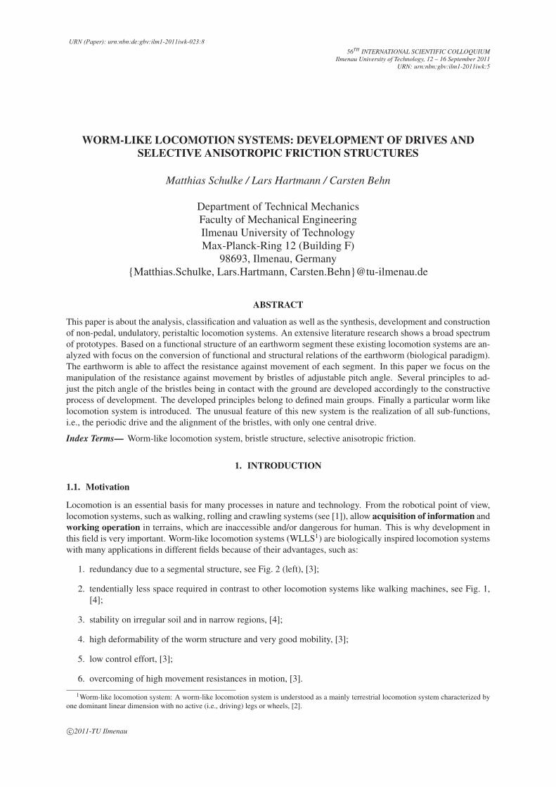
c 2011-TU Ilmenau 56 TH INTERNATIONAL SCIENTIFIC COLLOQUIUM Ilmenau University of Technology, 12 – 16 September 2011 URN: urn:nbn:gbv:ilm1-2011iwk:5 WORM-LIKE LOCOMOTION SYSTEMS: DEVELOPMENT OF DRIVES AND SELECTIVE ANISOTROPIC FRICTION STRUCTURES Matthias Schulke / Lars Hartmann / Carsten Behn Department of Technical Mechanics Faculty of Mechanical Engineering Ilmenau University of Technology Max-Planck-Ring 12 (Building F) 98693, Ilmenau, Germany {Matthias.Schulke, Lars.Hartmann, Carsten.Behn}@tu-ilmenau.de ABSTRACT This paper is about the analysis, classification and valuation as well as the synthesis, development and construction of non-pedal, undulatory, peristaltic locomotion systems. An extensive literature research shows a broad spectrum of prototypes. Based on a functional structure of an earthworm segment these existing locomotion systems are an- alyzed with focus on the conversion of functional and structural relations of the earthworm (biological paradigm). The earthworm is able to affect the resistance against movement of each segment. In this paper we focus on the manipulation of the resistance against movement by bristles of adjustable pitch angle. Several principles to ad- just the pitch angle of the bristles being in contact with the ground are developed accordingly to the constructive process of development. The developed principles belong to defined main groups. Finally a particular worm like locomotion system is introduced. The unusual feature of this new system is the realization of all sub-functions, i.e., the periodic drive and the alignment of the bristles, with only one central drive. Index Terms— Worm-like locomotion system, bristle structure, selective anisotropic friction. 1. INTRODUCTION 1.1. Motivation Locomotion is an essential basis for many processes in nature and technology. From the robotical point of view, locomotion systems, such as walking, rolling and crawling systems (see [1]), allow acquisition of information and working operation in terrains, which are inaccessible and/or dangerous for human. This is why development in this field is very important. Worm-like locomotion systems (WLLS 1 ) are biologically inspired locomotion systems with many applications in different fields because of their advantages, such as: 1. redundancy due to a segmental structure, see Fig. 2 (left), [3]; 2. tendentially less space required in contrast to other locomotion systems like walking machines, see Fig. 1, [4]; 3. stability on irregular soil and in narrow regions, [4]; 4. high deformability of the worm structure and very good mobility, [3]; 5. low control effort, [3]; 6. overcoming of high movement resistances in motion, [3]. 1 Worm-like locomotion system: A worm-like locomotion system is understood as a mainly terrestrial locomotion system characterized by one dominant linear dimension with no active (i.e., driving) legs or wheels, [2]. URN (Paper): urn:nbn:de:gbv:ilm1-2011iwk-023:8
-
Upload
phungkhanh -
Category
Documents
-
view
215 -
download
0
Transcript of Worm-like Locomotion Systems: Development of Drives … · ... ilm1-2011iwk:5 WORM-LIKE LOCOMOTION...
c©2011-TU Ilmenau
56TH INTERNATIONAL SCIENTIFIC COLLOQUIUMIlmenau University of Technology, 12 – 16 September 2011
URN: urn:nbn:gbv:ilm1-2011iwk:5
WORM-LIKE LOCOMOTION SYSTEMS: DEVELOPMENT OF DRIVES ANDSELECTIVE ANISOTROPIC FRICTION STRUCTURES
Matthias Schulke / Lars Hartmann / Carsten Behn
Department of Technical MechanicsFaculty of Mechanical EngineeringIlmenau University of TechnologyMax-Planck-Ring 12 (Building F)
98693, Ilmenau, Germany{Matthias.Schulke, Lars.Hartmann, Carsten.Behn}@tu-ilmenau.de
ABSTRACT
This paper is about the analysis, classification and valuation as well as the synthesis, development and construction
of non-pedal, undulatory, peristaltic locomotion systems. An extensive literature research shows a broad spectrum
of prototypes. Based on a functional structure of an earthworm segment these existing locomotion systems are an-
alyzed with focus on the conversion of functional and structural relations of the earthworm (biological paradigm).
The earthworm is able to affect the resistance against movement of each segment. In this paper we focus on the
manipulation of the resistance against movement by bristles of adjustable pitch angle. Several principles to ad-
just the pitch angle of the bristles being in contact with the ground are developed accordingly to the constructive
process of development. The developed principles belong to defined main groups. Finally a particular worm like
locomotion system is introduced. The unusual feature of this new system is the realization of all sub-functions,
i.e., the periodic drive and the alignment of the bristles, with only one central drive.
Index Terms— Worm-like locomotion system, bristle structure, selective anisotropic friction.
1. INTRODUCTION
1.1. Motivation
Locomotion is an essential basis for many processes in nature and technology. From the robotical point of view,
locomotion systems, such as walking, rolling and crawling systems (see [1]), allow acquisition of information and
working operation in terrains, which are inaccessible and/or dangerous for human. This is why development in
this field is very important. Worm-like locomotion systems (WLLS1) are biologically inspired locomotion systems
with many applications in different fields because of their advantages, such as:
1. redundancy due to a segmental structure, see Fig. 2 (left), [3];
2. tendentially less space required in contrast to other locomotion systems like walking machines, see Fig. 1,
[4];
3. stability on irregular soil and in narrow regions, [4];
4. high deformability of the worm structure and very good mobility, [3];
5. low control effort, [3];
6. overcoming of high movement resistances in motion, [3].
1Worm-like locomotion system: A worm-like locomotion system is understood as a mainly terrestrial locomotion system characterized by
one dominant linear dimension with no active (i.e., driving) legs or wheels, [2].
URN (Paper): urn:nbn:de:gbv:ilm1-2011iwk-023:8

Walking
Wheels
Meander
Peristalsis
Fig. 1. Tendential required space of locomotion systems, [5]
The classification scheme of motion of an earthworm is a redundant system, as mentioned above. Because of the
segmental structure it is less accident-sensitive than other systems. If there is a dysfunction of one segment, the
system is still able to move. An additional advantage of worm-like locomotion is the possibility to move in pipesAND on a plane.
1.2. The biological paradigm
The biological paradigm of the WLLS, considered in this paper, is the earthworm. An earthworm is placed in the
large phylum of segmented worms, particularly in the subclass of the oligochaeta because of the bristles on each
segment of the worm, see Fig. 2 (left), [6].
Fig. 2. left: segments of an earthworm with bristles, [7]; right: peristaltic motion of an earthworm, [8]
The essential elements, which are necessary for the locomotion of the worm, are:
• the hydrostatic skeleton,
• two muscle systems which contract and relax antagonistically,
• the bristle-like setae preventing backwards slipping.
The hydrostatic skeleton (coelom) is built of separate segments and each segment is filled with a fluid. There
are four pairs of bristles at each segment of the earthworm, preventing backwards slipping, see Fig. 2 (left). An
extensible body wall (epidermis) contains two muscle systems: the circular and the longitudinal muscles. In
Fig. 2 (right) the motion of the earthworm is shown by rhythmical muscle contraction waves from head to the end
(peristalsis). If the longitudinal muscles relax and the circular muscles contract the segment becomes longer and
slighter. In contrast, the segment shortens and thickens, when the longitudinal muscles contract and the circular
muscles relax. The reason for the changing structure form of the tube is the constant segment volume, so that the
diameter is doubled and the length is divided into quarters by contraction of the longitudinal muscles, [9]. The
forward motion of a worm is shown in three steps in Fig. 2 (right):

(a) The worm segments in 1st and the 3rd quarter are short and thick because of the contraction of the longitudinal
muscles. These segments anchor in the environment due to the bristles at each segment. All other segments
have no contact to the ground, while the circular muscles contract and the longitudinal muscles of these
segments relax, [8].
(b) The contraction of the circular muscles and the relaxation of the longitudinal muscles cause a motion of a
few of the segments. Simultaneously other segments shorten and thicken because the muscle systems of the
worm operate antagonistically, [8].
(c) The front segments are short and thick again and anchor with the environment, see (a). Slenderizing the back
segments they loose their ground contact and so the worm performs a rectilinear motion, [8].
The structural and functional relations, which allow the motion of an earthworm, are determined in Fig. 3. The
essential parts in locomotion of the earthworm are the changing of relative position and the interference of themovement resistance.
manipulation of the resistance against movement
AEprotractor muscle
(extend)
AEretractor muscle
(retract)
TEcoelom
(hydroskeleton)
AElongitudinal
muscle
AEcircular muscle
EE
segment
relative change in position
AETE
EE
actuation elementtransmission elementeffect elementenergy flow
y�x , z�y ,�z , ,
segm. xsegm. x+1
x‘
�x
......
outer covering(compliant)
bristleanisotropic friction
Fig. 3. Functional structure of an earthworm segment, [10]
There are two possibilities to influence the movement resistance by the earthworm, see Fig. 3:
• anisotropic2 friction by bristles,
• changing contact with the environment by varying the tube diameter.
The main difference between these two possibilities is the realization of different movement resistances by
anisotropic friction maintaining the friction pairing and the contact force. But, the contact force and the
friction pairing can be modified by varying the diameter of a segment. If a segment is slight no contact to the
environment is reached and so it is not necessary to overcome the movement resistance. This effect is mostly used
in pipes. In addition to the functional structure of an earthworm segment (Fig. 3) we will present and evaluate
several prototypes of WLLS in Chapter 2, due to this functional structure.
2. STATE OF THE ART
This chapter should give an overview of the prototypes of worm-like locomotion systems. The authors introduce
a few prototypes from Ilmenau University of Technology and from other research centers knowing that this list is
not intended to be exhaustive.
2Anisotropy: direction-dependence on a feature of a process
2.1. WLLS at Ilmenau University of Technology
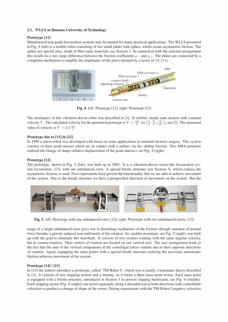
Prototype [11]Miniaturized non-pedal locomotion systems may be needed for many practical applications. The WLLS presented
in Fig. 4 (left) is a mobile robot consisting of two small plates with spikes, which create asymmetric friction. The
spikes are special ones, made of fiber-optic materials, see Section 3. In connection with the selected arrangement
this results in a very large difference between the friction coefficients μ− and μ+. The plates are connected by a
compliant mechanism to amplify the amplitudes of the piezo element by a factor of 10, [11].
Fig. 4. left: Prototype [11]; right: Prototype [12]
The mechanics of this vibration-driven robot was described in [1]. It exhibits steady-state motion with constant
velocity V . The calculated velocity for the presented prototype is V = aΩ2 sin
(π2 · F−−F+
F−+F+
), see [1]. The measured
value of velocity is V = 4.5 cms
.
Prototype due to [13] in [12]In 1998 a micro-robot was developed with focus on some applications in minimal invasive surgery. This system
consists of three point masses which are in contact with a surface via dry sliding friction. Two SMA-actuators
realized the change of shape (relative displacement of the point masses), see Fig. 4 (right).
Prototype [12]The prototype, shown in Fig. 5 (left), was built up in 2003. It is a vibration-driven worm-like locomotion sys-
tem locomotion, [12], with one unbalanced rotor. A special bristle structure (see Section 3), which realizes the
asymmetric friction, is used. First experiments have proven the functionality that we are able to achieve movement
of the system. Due to the bristle structure we have a prespecified direction of movement on the system. But the
Fig. 5. left: Prototype with one unbalanced rotor, [12]; right: Prototype with two unbalanced rotors, [12]
usage of a single unbalanced rotor gives rise to disturbing oscillations of the friction (though variation of normal
force) besides a gravity-induced non-uniformity of the rotation. So, another prototype, see Fig. 5 (right), was built
up with the goal to eliminate this drawback. It consists of two exciters rotating with the same angular velocity,
but in counter-rotation. Their centers of rotation are located on one vertical axis. The new arrangement leads to
the fact that the sum of the vertical components of the centrifugal forces vanishe due to their opposite directions
of rotation. Again, equipping the mass points with a special bristle structure realizing the necessary anisotropic
friction achieves movement of the system.
Prototype [14] / [15]In [15] the authors introduce a prototype, called ‘TM-Robot I’, which was to justify a kinematic theory described
in [1]. It consists of two stepping motors and a dummy, so it forms a three mass point worm. Each mass point
is equipped with a bristle-structure, introduced in Section 3 to prevent slipping backwards, see Fig. 6 (middle).
Each stepping motor (Fig. 6 (right)) can travel separately along a threaded rod in both directions with controllable
velocities to produce a change of shape of the worm. During experiments with the TM-Robot I negative velocities

Fig. 6. left: TM-Robot I, [14]; middle: Bristle-structure, [16]; right: Stepping motor, [14]
occur, [14]. In a further stage of development, a set of wheels with a self-locking mechanism (Section 3) is
used instead of the bristle structure to prevent backward motion. This construction nearly perfectly ensures the
fulfillment of the differential constraints xi ≥ 0.
Prototype [1]This vibration-driven locomotion system, presented in [1], consists of two bodies connected by a spring. The
motion is excited by two unbalance rotors attached to the respective bodies. Control of the two DC-motors is done
using a LabVIEW program running on a notebook with data being transferred via USB to a control unit. The
Fig. 7. Vibration-driven locomotion system, [1]
theoretical background of this vibration-driven locomotion system is discussed in detail in [17]. The benefit of this
developed prototype lies in the exact knowledge of the system parameters, which led to good agreement between
• the theoretically obtained results based on analytical methods (method of averaging),
• numerical integration of the exact equations of motion, and
• measured results in the experiment.
The velocity can be controlled by changing the initial value of the phase shift between the rotations of the rotors.
The direction of the motion can be changed by varying the difference between the natural frequency of the system
and the angular velocities of the rotors in sign (without changing the direction of rotation of the exciters).
Prototype in [10]For the purpose of validating theoretical control results by experiments a new locomotion system is developed (the
‘TM-Robot II’). It is designed to have a better dynamical behavior than older systems, see [14]. The drive is by
motors, pulleys and springs as one can see in Fig. 8.
Fig. 8. TM-Robot II, [10]

At last, a new field is the design of ferrofluid-based locomotion systems, see [18]. There are two main future-
oriented trends:
1. the realization of a locomotion based on the deformation of magnetic material of finite volume, [18],
2. the realization of locomotion based on the deformation of a free surface of a magnetic fluid layer in a
traveling magnetic field, ([18]).
2.2. Prototypes from abroad
Cube [19]A modular worm-like robot, Fig. 9 (left), named Cube, is presented in [19]. This is the simplest kind of modular
robot composed of 8 equal linked modules (1-modular robot). The locomotion is achieved by the propagation
of waves which travel through the robot from tail to the head. The entirely locomotion controller is centrally
embedded into an FPGA processor.
Fig. 9. left: Prototype Cube, [19]; right: Mobile Robot with Worm-like Movement, [20]
The authors in [20] present the development of a multiple joint mobile mini-robot, see Fig. 9 (right), which is able
to perform a creeping motion. The main objective of the research activities is to determine the robot model for
evaluating its worm-like movement possibilities, and an adequate computer control system was developed, as well.
The prototype of this one was implemented by means of I/0 boards and LabVIEW programming.
Inchworm Robot [21]The development of a bidirectional inch-worm robot based on a modular concept is arranged in [21]. The prototype,
shown in Fig. 10 (left), can travel along the guiding walls in both directions. There are two solenoid actuators on
each of the cart: one for gripping action (emulating the gripper) and the other for extension action (emulating
the extensor). Wheels are built under all carts to support the weight of the robot. In addition to the inch-worm
prototype a 2D planar model was planned and designed. Traveling along bends is reached with pneumatic cylinders
changing the shape of the structure.
Fig. 10. left: Inchworm Robot, [21]; right: Mechatronic worm-like locomotion system, [22]
Mechatronic worm-like locomotion system [22]A mechatronic WLLS traveling bidirectional in pipes and tubes, see Fig. 10 (right), is introduced in [22]. The
system, which consists only of one central drive and compliant mechanisms, can move in forward and backward
direction because of a selective anisotropic friction. Currently the system can be used in pipes with a diameter of
40 mm, and the authors plan a usage in minimal invasive surgery.
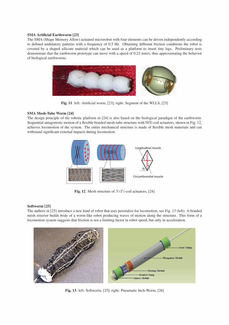
SMA Artificial Earthworm [23]The SMA (Shape Memory Allow) actuated microrobot with four elements can be driven independently according
to defined undulatory patterns with a frequency of 0.5 Hz. Obtaining different friction conditions the robot is
covered by a shaped silicone material which can be used as a platform to insert tiny legs. Preliminary tests
demonstrate that the earthworm prototype can move with a speed of 0.22 mm/s, thus approximating the behavior
of biological earthworms.
Fig. 11. left: Artificial worm, [23]; right: Segment of the WLLS, [23]
SMA Mesh-Tube Worm [24]The design principle of the robotic platform in [24] is also based on the biological paradigm of the earthworm.
Sequential antagonistic motion of a flexible braided mesh-tube structure with NiTi coil actuators, shown in Fig. 12,
achieves locomotion of the system. The entire mechanical structure is made of flexible mesh materials and can
withstand significant external impacts during locomotion.
����������� �������
����� �������� ������
�
Fig. 12. Mesh structure of NiT i-coil actuators, [24]
Softworm [25]The authors in [25] introduce a new kind of robot that uses peristalsis for locomotion, see Fig. 13 (left). A braided
mesh exterior builds body of a worm-like robot producing waves of motion along the structure. This form of a
locomotion system suggests that friction is not a limiting factor in robot speed, but only in acceleration.
Fig. 13. left: Softworm, [25]; right: Pneumatic Inch-Worm, [26]

Pneumatic inch-worm [26]In [26] an inch-worm for pipe inspection is designed, which uses only one pneumatic drive, see Fig. 13 (right).
The robots consists of a rear clamp, the elongation module, and the front clamp working sequentially as the air
flows to each chamber.
Crawling robot using tiny ultrasonic linear actor in [27]The crawling robot using a ultrasonic piezo actuator in [27] is designed for inspection of small sized pipes. This
actuator realizes a continuous motion and a high speed on the system. In Fig. 14 (left) two realizable principles of
the locomotion mechanism are shown:
(a) earthworm-like locomotive mechanism
(b) crawling based locomotive mechanism.
Fig. 14. left: Prototype [27]; right: Prototype and bristles, [28]
In-pipe micromachine [28]This micromachine for moving in thin pipes utilises a DC-micromotor with planetary gearhead. The motion
principle of this in-pipe micromachine, see Fig. 14 (right), is based on a friction difference between passive smart
bristles, of micromachine and inner pipe wall.
3. SUMMARY OF STATE OF THE ART
As shown in Chapter 2 there are various systems and prototypes of worm-like locomotion systems. Finally we
will give a short summary and an evaluation of the introduced systems in the following table, where we use the
functional structure (Fig. 3) as an appraisal criterion.
Analyzing the different systems we draw some conclusions which shall lead us to new directions for development:
• only a few prototypes realize peristaltic locomotion,
• kinematic gaits are pre-defined and cannot be changed,
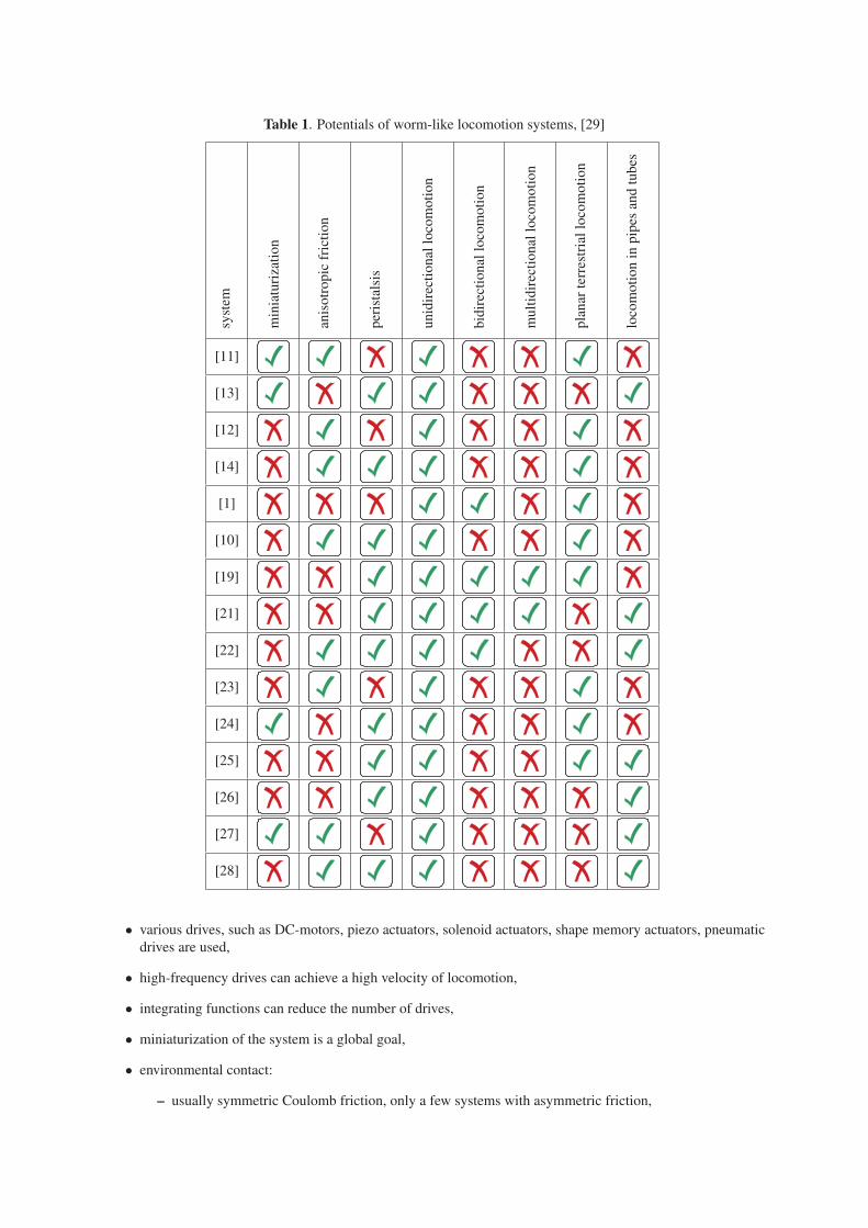
Table 1. Potentials of worm-like locomotion systems, [29]
syst
em
min
iatu
riza
tio
n
anis
otr
op
icfr
icti
on
per
ista
lsis
un
idir
ecti
on
allo
com
oti
on
bid
irec
tio
nal
loco
mo
tio
n
mu
ltid
irec
tio
nal
loco
mo
tio
n
pla
nar
terr
estr
ial
loco
mo
tio
n
loco
mo
tio
nin
pip
esan
dtu
bes
[11]
[13]
[12]
[14]
[1]
[10]
[19]
[21]
[22]
[23]
[24]
[25]
[26]
[27]
[28]
• various drives, such as DC-motors, piezo actuators, solenoid actuators, shape memory actuators, pneumatic
drives are used,
• high-frequency drives can achieve a high velocity of locomotion,
• integrating functions can reduce the number of drives,
• miniaturization of the system is a global goal,
• environmental contact:
– usually symmetric Coulomb friction, only a few systems with asymmetric friction,

– bidirectional locomotion in pipes and tubes with clamping mechanisms based on symmetric Coulomb
friction,
– planar bidirectional locomotion is yet realized by varying the diameter of a segment to change the
environmental contact,
– bristles with given pitch angle realize anisotropic friction but not a bidirectional locomotion,
– selective anisotropic friction by orientation of the bristles can perform a bidirectional locomotion.
Anisotropic friction
As carried out friction is an essential feature for locomotion, due to an environmental ground contact of the worm.
Usually prototypes for pipes and tubes use symmetric Coulomb friction, where the normal force is realized by
clamping mechanisms. We focus a locomotion system with a constant contact force and anisotropic frictionbased on Coulomb’s law. There are conditions optimizing the locomotion, like the following: to move forward
easily a low friction force is required. In contrary, a high friction force in backward direction inhibits slipping
effects of the system. Figure 15 visualizes the demanded anisotropic Coulomb friction force depending on the
velocity.
Ff :=
⎧⎨⎩
−F+ , x > 00 , x = 0F− , x < 0
x
F (x)
F
- F+
-
f
Fig. 15. Anisotropic friction force depending on velocity
There are a few technical structures realizing an anisotropic friction:
1. Bristles made of glass fibers
The system developed in [11] uses a tuft of very thin glass filaments (10μm) with an prespecified pitch
angle, see Fig. 16 (left). These spikes can anchor in the underground, even in a glass plate, but they cannot
be used for heavy systems.
Fig. 16. left: Tuft with prespecified pitch angle; right: Microscope image of a tuft, [11]
2. Velcro-structure
Handling heavy locomotion systems the glass fiber tufts have to be replaced by a structure with higher
stiffness, such as a velcro-structure, see Fig. 17.
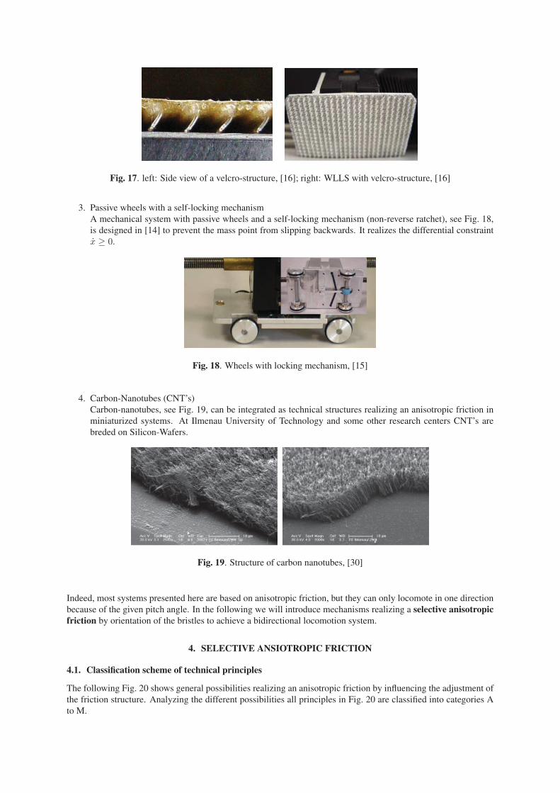
Fig. 17. left: Side view of a velcro-structure, [16]; right: WLLS with velcro-structure, [16]
3. Passive wheels with a self-locking mechanism
A mechanical system with passive wheels and a self-locking mechanism (non-reverse ratchet), see Fig. 18,
is designed in [14] to prevent the mass point from slipping backwards. It realizes the differential constraint
x ≥ 0.
Fig. 18. Wheels with locking mechanism, [15]
4. Carbon-Nanotubes (CNT’s)
Carbon-nanotubes, see Fig. 19, can be integrated as technical structures realizing an anisotropic friction in
miniaturized systems. At Ilmenau University of Technology and some other research centers CNT’s are
breded on Silicon-Wafers.
Fig. 19. Structure of carbon nanotubes, [30]
Indeed, most systems presented here are based on anisotropic friction, but they can only locomote in one direction
because of the given pitch angle. In the following we will introduce mechanisms realizing a selective anisotropicfriction by orientation of the bristles to achieve a bidirectional locomotion system.
4. SELECTIVE ANSIOTROPIC FRICTION
4.1. Classification scheme of technical principles
The following Fig. 20 shows general possibilities realizing an anisotropic friction by influencing the adjustment of
the friction structure. Analyzing the different possibilities all principles in Fig. 20 are classified into categories A
to M.

Anisotropic friction by bent fibers
angle of the fiber bundle preset on the support system
angle of the fiber bundles adjustable ( y , x )
multiple bundle arrays
bundles are set together
one bundle array
each bundle is set seperatly
fiber bundle array with m x n
bundle rows
fiber bundle
support system
bundles simply supported
deploy the compliance of the
bundles
bundles anytime in contact with the
groundz = const.
bundles not anytime in contact with the
groundz � const.
angles are set together
angles are set seperatly
multidirectionalorientation
z � const.z � const.
multidirectionalorientation
z = const.z � const.
unidirectionalorientation
z = const.z = const.
multidirectionalorientation
z � const.z � const.
x1y1z1 x2y2
z2 x1'y1'z1'
fiber bundle row with m biber bundles
special case:n=1 -> �z by rotation possibele
special case:m=1
rot. -> rot.
bundle
transl. -> rot.
h
h
h
�y
z
x
y y , x
�y x
z
z
�y x
at least two actuators necessary
at least one actuator necessarye.g.: excentric bold moves layer in x- & y- direction
xyz
xyz
x1y1z1 x2y2
z2 x1'y1'z1'
x�y
z
A
B
C
E
F
G
H
I
J
K
L
M
multidirectionalorientation
z � const.z = const.
D
Fig. 20. Classification scheme for selective anisotropic friction, see [10]
4.2. Technical Principles
The categories A to F introduce solutions with a given orientation of the bristles in a support system. Systems
whose bristles’ orientation is achieved via deformation of the bristles are categorized in F to M.
In Category A there is no influence to the adjustment of the friction structure. The bristles realize an anisotropic
friction for an unidirectional locomotion by a given pitch angle and no modification is reached. Contrary, in
Category B the orientation of the bristles can be modified by a rotation of the support system. A rotation of 180
degrees is required to realize a bidirectional linear motion. In combination with different drives, such as direct
drive or gear drive, a few technical principles are developed, see Fig. 21.
B1 B2 B3 B4 B5
B6
direct drive
rack-wheeldrive
friction wheel drive
worm drivebelt drive
rack and pinion drive
Fig. 21. Principles of Category B, [10]
It would be an advantage to switch the orientation of the bristles frictionless, that means the system gets not out of
position during the changeover procedure. Category C focuses solutions disrupting the contact to the environment
while rotating the support system with the oriented bristles. An additional drive is needed to raise the whole system
in z-direction, see Fig. 22.

C1 C2.1 C2.2
C2.2.4
B
belt driveRot. Transl.
C2.2.5
B
slider-crack mechanism
Rot. Transl.
C2.2.6 C2.2.7
B
cam mechanism
Rot. Transl.
C1.1
screw drive
B C2.2.3
B
rack and pinion driveRot. Transl.
wedge mechanismTransl.Rot.
B
Fig. 22. Principles of Category C, [10]
In Category D there is again a support pattern with fixed bristles of given pitch angle. But, in contrast to the other
categories mentioned above, we have several support systems with opposite oriented bristles realizing a selective
anisotropic friction due to the contact with the environmental ground. Once a support system is having contact
with the ground while the others are free, we get the forward motion. Otherwise the backward motion is achieved.
In Sub-category D1, see Fig. 23, the shifting support systems are uncoupled whereas in Sub-category D2 the
adjustment is coupled by mechanisms.
z1
D1
z2
z3
z1
D2
z2
z1
z1 z2 z1
P1 �P1
D2.1
z1 z2 z3
D1.1
p1 p2 p3
z1 z2 z1D2.2
transl.transl.SMA-actuator
hydr./pneum.transl.rot.
screw drive
SMA-support system, 3 positions shown
D2.3special case: one support system
Fig. 23. Principles of Category D, [10]
For further description of the principles of the categories E to M the reader’s attention is invited to [10].
4.3. Drive selection
Realizing the technical principles, introduced in Section 4.2 and [10], actuators are required. In this section we
deal with different drives and point out their pros and cons.
• DC-motor:
pros: high dynamics, wide speed range, simple control of motor speed, good start-up behavior, low costs
cons: brush wear, low torque, measuring system not integrated, heat removal by rotor shaft
• AC motor:
pros: very high dynamics, wide speed range, high torque,
cons: complex triggering, measuring system not integrated, high costs
• electromagnet:
pros: simple structure, high forces
cons: small strokes, low force on large stroke
• piezo actuator:
pros: direct drive, high forces, high dynamics, high repeat accuracy, high efficiency, small size
cons: small strokes, temperature dependency, hysteresis, tension sensitive
• stepping motor:
pros: constant power device, high dynamics, holding torque, small steps, high positioning capability
cons: speed increases while torque decreases, vibrations, start-stop-frequency
• pneumatic and hydraulic drive:
pros: high forces and moments, linear movements,
cons: high costs, requiring fluid, pressure generator, pipes and valves
• Shape memory actuator:
pros: high recoverable plastic strain, small size, simple structure, high forces
cons: heating up, only one actor direction, large strokes require long wires, requiring restoring force.
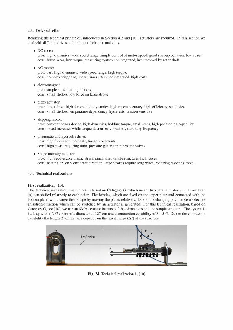
4.4. Technical realizations
First realization, [10]:This technical realization, see Fig. 24, is based on Category G, which means two parallel plates with a small gap
(a) can shifted relatively to each other. The bristles, which are fixed on the upper plate and connected with the
bottom plate, will change their shape by moving the plates relatively. Due to the changing pitch angle a selective
anisotropic friction which can be switched by an actuator is generated. For this technical realization, based on
Category G, see [10], we use an SMA actuator because of the advantages and the simple structure. The system is
built up with a NiT i wire of a diameter of 127 μm and a contraction capability of 3 – 5 %. Due to the contraction
capability the length (l) of the wire depends on the travel range (Δl) of the structure.
a
SMA wire
l
�l
Fig. 24. Technical realization 1, [10]

Second realization, [10]:In [10] the author introduces principles of Category D achieving a selective anisotropic friction by different pre-
specified orientation of bristles. The orientation of bristles, which are fixed with the support system, is prespecified
because of the given pitch angle and cannot be changed. We have several support systems with different oriented
bristles, which can lifted up and lowered down by mechanisms. The locomotion system moves forward or back-
ward according to the segments with environmental contact.
Various actuators are possible for lifting up and lowering down the support systems, to switch the direction of
motion. This design uses an SMA wire as lifting actuator and a leaf spring reverses the lifting. The prototype is
shown in Fig. 25.
Fig. 25. left: Uplifted support system; right: Lowered support system, [10]
Third realization, [29]:An other technical realization based on Category D is the mechanism introduced in [29]. The working principle,
pointing out a selective anisotropic friction, is similar to the second prototype. But, the switching mechanism
is a rotatory drive in combination with a screw gear and a transmission by a wedge gear. We present detailed
information of this principle in Section 5. The lifted and lowered support system of one segment are shown in
Fig. 26.
Fig. 26. top: Uplifted support system; bottom: Lowered support system, [29]
5. PROTOTYPE
5.1. Design and sizing of structural components
In Section 4 we sketched a few principles and realizations for a selective anisotropic friction. Due to the switching
mechanism an actuator is required, but yet we do not have a locomotion. Only a relative change of position of
the elements by a periodic drive and a selective anisotropic friction causes a bidirectional locomotion. However,
this will need one or more actuators for each sub-function, control systems and a lot of wires for power supply
and measurements. It would be a big advantage to summarize some sub-functions, i.e., periodic drive and the
alignment of the bristles, with only one central drive. In [29] a new system with the unusual feature of integration
of sub-functions is designed accordingly to the constructive process of development, see [31].
The artificial worm consisting of three elements travels with the following kinematic gait, presented in Fig. 27.
Realizing the periodic change of position of the elements the drive is built up by a stepping motor and a cylindrical
(2)
(2)
(2)
(2)
(3) (1)
(1)(3)
(3) (1)
(1)(3)
x
Fig. 27. Kinematic gait, see [32]
cam gearing. There is no matter about the rotational direction of the motor because of the curvature of the cam
drum. Therefore, the rotational direction is an additional information and can be used to switch the alignment of
the bristles changing the direction of locomotion. A self-toggling clutch with limited travel range, see Fig. 28,
operating by different rotational direction, is a basis for the functional integration of the system.
�
� b�
s�
spring-loadedstop
�
x�
�
x�
Fig. 28. Principles of a self-toggling clutch with limited travel range, [29]
One central drive, namely a stepping motor, accomplishes both sub-functions using a cam gearing as periodic
drive and a combination of a screw gear and a wedge gear as switching mechanism to align the bristles. We focus
on the following principle for our construction, see Fig. 29.
M
�
x�y�y�
x�y�
x�
Fig. 29. Technical principle of a worm using one central drive, [29]
As one can see in Fig. 27 even one element is pushed while the others do not move, so three phases perform one
cycle of motion. We have a synchronous direction phase, a counter-direction phase and dwell phase, respectively,
on each link per cycle, see Fig. 30.

y
s
0�
�32
I II IIIDisplacement between
segment 1 and 2
Displacement between segment 2 and 3
�34 �2
H
Fig. 30. Displacement variation between the segments depending on drive-angle, [29]
One cycle of the stepping motor is divided in three equal parts(23π or 120◦
)realizing the three phases presented
above. The motion scheme in Fig. 30 is described by a smooth and shock-free transfer function. We consider the
Bestehorn Sinoide, defined as f(z) = z − 12π sin (2πz), because of the well kinematic properties and get (1) to
estimate the minimal radius of the cam drum, see [33]:
rgz ≥ sHϕ
Cv tan(μmin) =sHϕ
(max{f ′(z)}) tan(μmin). (1)
The radius can evaluated by rgz ≥ 24.8mm ≈ 25mm using sH = 15mm, ϕ = 23π, Cv = 2 and μmin = 60◦.
Comparing [34] the curvature of the cam drum and the velocity can determined, see Fig. 31, which are equal to the
theoretical one in [32].
Fig. 31. left: Displacement; right: Velocity, [29]
The required driving force is FA ≥ 1.2N using Newton’s second law (2):
mx = −mg sin(ϑ)− μmg cos(ϑ) + FA. (2)
Figure 32 sketch the torque of the stepping motor with (3):
��
Fu
FAta
tr
�
�
Fig. 32. Forces on a Cam gearing, [29]
Merf = Jϕ+FA rgztan(α)
≥ 51.98Nmm. (3)

5.2. Assembly, [29]
The prototype of the artificial worm with three segments and one central drive for all sub-functions is presented in
Fig. 33.
Fig. 33. Prototype of the artificial worm, [29]
In the following we present several components of the WLLS in detail, see [29]:
• driving unit with stepping motor and cam drum
Fig. 34. Motor segment with stepping motor and cam drum, [29]
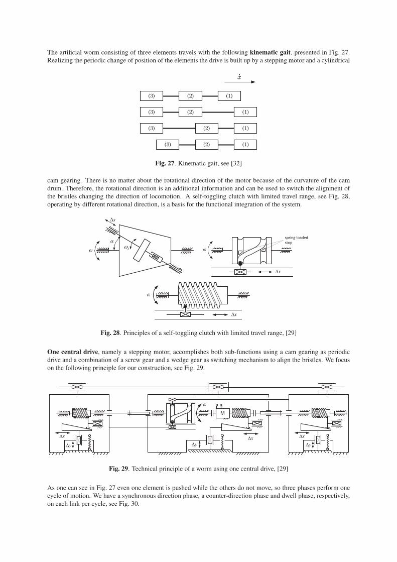
• drive element: cam drum
Fig. 35. Cam drum in different views; left: dwell phase; middle & right: movement phase, [29]
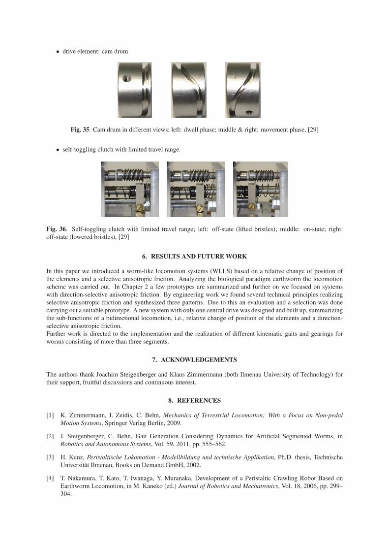
• self-toggling clutch with limited travel range.
Fig. 36. Self-toggling clutch with limited travel range; left: off-state (lifted bristles); middle: on-state; right:
off-state (lowered bristles), [29]
6. RESULTS AND FUTURE WORK
In this paper we introduced a worm-like locomotion systems (WLLS) based on a relative change of position of
the elements and a selective anisotropic friction. Analyzing the biological paradigm earthworm the locomotion
scheme was carried out. In Chapter 2 a few prototypes are summarized and further on we focused on systems
with direction-selective anisotropic friction. By engineering work we found several technical principles realizing
selective anisotropic friction and synthesized three patterns. Due to this an evaluation and a selection was done
carrying out a suitable prototype. A new system with only one central drive was designed and built up, summarizing
the sub-functions of a bidirectional locomotion, i.e., relative change of position of the elements and a direction-
selective anisotropic friction.
Further work is directed to the implementation and the realization of different kinematic gaits and gearings for
worms consisting of more than three segments.
7. ACKNOWLEDGEMENTS
The authors thank Joachim Steigenberger and Klaus Zimmermann (both Ilmenau University of Technology) for
their support, fruitful discussions and continuous interest.
8. REFERENCES
[1] K. Zimmermann, I. Zeidis, C. Behn, Mechanics of Terrestrial Locomotion; With a Focus on Non-pedalMotion Systems, Springer Verlag Berlin, 2009.
[2] J. Steigenberger, C. Behn, Gait Generation Considering Dynamics for Artificial Segmented Worms, in
Robotics and Autonomous Systems, Vol. 59, 2011, pp. 555–562.
[3] H. Kunz, Peristaltische Lokomotion - Modellbildung und technische Applikation, Ph.D. thesis, Technische
Universität Ilmenau, Books on Demand GmbH, 2002.
[4] T. Nakamura, T. Kato, T. Iwanaga, Y. Muranaka, Development of a Peristaltic Crawling Robot Based on
Earthworm Locomotion, in M. Kaneko (ed.) Journal of Robotics and Mechatronics, Vol. 18, 2006, pp. 299–
304.

[5] N. Saga, T. Nakamura, Development of a peristaltic crawling robot using magnetic fluid on the basis of the
locomotion mechanism of the earthworm, in Smart materials and structures, Vol. 13, S. 566–569, 2004.
[6] W. Peters, V. Walldorf, Der Regenwurm LUMBRICUS TERRESTRIS L. Eine Praktikumsanleitung, Quelle
& Meyer Verlag, Heidelberg, 1986.
[7] http://de.wikipedia.org/wiki/Regenwurm, abgerufen am 20. Juli 2011.
[8] N. A. Campbell, J. B. Reece, Biologie, 6. Aufl., Spektrum Akademischer Verlag Heidelberg, 2003.
[9] W. Westheide, R. Rieger (ed.), Spezielle Zoologie - Teil 1: Einzeller und wirbellose Tiere, Gustav Fischer
Verlag, 1996.
[10] M. Schulke, Entwurf, Steuerung und Analyse biomimetischer wurmartiger Bewegungssysteme, M.Sc. thesis,
Technische Universität Ilmenau, 2011.
[11] F. Weise, Entwurf und Konstruktion einer neuartigen Aktuatorik für ein biomimetisches Bewegungssystem,
M.Sc. thesis, Technische Universität Ilmenau, 2002.
[12] J. Huang, Modellierung, Simulation und Entwurf biomimetischer Roboter basierend auf apedaler undula-torischer Lokomotion, Ph.D. thesis, Technische Universität Ilmenau, Universitätsverlag Ilmenau, 2002.
[13] D. Riemer, Linearantrieb Deutsches Patent, DE 19853324A1, Nov. 1998.
[14] K. Abaza, Ein Beitrag zur Anwendung der Theorie undulatorischer Lokomotion auf mobile Roboter -Evaluierung theoretischer Ergebnisse an Prototypen, Ph.D. thesis, Technische Universität Ilmenau, Univer-
sitätsverlag Ilmenau, 2007.
[15] J. Steigenberger, C. Behn, K. Zimmermann, K. Abaza, Worm-like Locomotion – Theory, Control and Ap-
plication, in Proceedings of the 3rd International Symposium on Adaptive Motion in Animals and Machines(AMAM), Ilmenau (Deutschland), 25–30 September, 2005.
[16] C. Behn, Adaptive Control of Straight Worms without Derivative Measurement, in Multibody System Dy-namics, Vol. 26, 2011, pp. 213–243.
[17] K. Zimmermann, I. Zeidis, N. Bolotnik, M. Pivovarov, Dynamics of a two-module vibration-driven system
moving along a rough horizontal plane, in Multibody System Dynamics, Vol. 22, 2009, pp. 199–219.
[18] K. Zimmermann, V. A. Naletova, I. Zeidis, V. Böhm, E. Kolev, Modelling of locomotion systems using
deformable magnetizable media, in Journal of Physics: Condensed Matter, Vol. 18, No. 38, 2006, pp. 2973–
2983.
[19] J. González-Gómez, E. Aguayo, E. Boemo, Locomotion of a Modular Worm-like Robot using a FPGA-based
embedded MicroBlaze Soft-processor, in Proceedings of the 7th International Conference on Climbing andWalking Robots (CLAWAR) 2004, Madrid (Spanien), Springer Verlag, pp. 869–878, 2004.
[20] B. Gramescu, C. Nitu, N. Alexandrescu, Modeling of a Mobile Robot with Worm-like Movement, in Eurocon2005 - The International Conference on Computer as a Tool, Vol. 2, Belgrad (Serbien), pp. 1204–1207, 2005.
[21] S. H. Yeo, I.-M. Chen, R. S. Senanayake, P. S. Wong, Design and Development of a planar Inchworm Robot,
in Proceedings of the 17th International Symposium on Automation and Robotics in Construction (ISARC),Taipei (Taiwan), pp. 1–6, 2000.
[22] D. Riemer, M. Lorenz, J. Rost, Wurmartiges mechatronisches Bewegungssystem für rohrartige Elemente, in
KEM Informationsvorsprung für Konstrukteure (08/2010), pp. 16–17, 2010.
[23] A. Menciassi, S. Gorini, G. Pernorio, P. Dario, A SMA Actuated Artificial Earthworm, in Proceedings IEEEInternational Conference on Robotics and Automation (ICRA’04), New Orleans (USA), pp. 3282–3287,
2004.
[24] S. Seok, C. D. Onal, R. Wood, D. Rus, S. Kim, Peristaltic Locomotion with Antagonistic Actuators in Soft
Robotics, in Proceedings of IEEE International Conference on Robotics and Automation (ICRA), pp. 1228–
1233, 2010.

[25] A. S. Boxerbaum, H. J. Chiel, R. D. Quinn, A new theory and methods for creating peristaltic motion in a
robotic platform, in IEEE International Conference on Robotics and Automation (ICRA) 2010, Anchorage
(Alaska), pp. 1221–1227, 2010.
[26] J. Jinwan Lim, H. Park, S. Moon, B. Kim, Pneumatic robot based on inchworm motion for small diameter
pipe inspection, in Proceedings of the 2007 IEEE International Conference on Robotics and Biomimetics,
Sanya (China), pp. 330–335, 2007.
[27] H. Park, B. Kim, J. O. Park, S.-J. Yoon, A Crawling Based Locomotive Mechanism Using a Tiny Ultrasonic
Linear Actuator (TULA), in 39th International Symposium on Robotics 2008, Seoul (Korea), pp. 85–90,
2008.
[28] M. Dovica, M. Gorzás, J. Kováè, Š. Ondoèko, In-Pipe Passive Smart Bristled Micromachine, Technis-
che Universität Košice, Fakultät für Maschinenbau, 2005, www.bmf.hu/conferences/SAMI2004/dovica.pdf,
abgerufen am 20.07.11.
[29] L. Hartmann, Modellierung und Entwurf eines biomimetischen Roboters, M.Sc. thesis, Technische Univer-
sität Ilmenau, 2011.
[30] http://www.tu-ilmenau.de/fakmn/Neue-Katalysatoren.1538.0.html, abgerufen am
11.12.2010.
[31] VDI-Richtlinie 2221: Methodik zum Entwickeln und Konstruieren technischer Systeme und Produkte, VDI-
Gesellschaft Produkt- und Prozessgestaltung (GPP), 1993.
[32] J. Steigenberger, Modeling artificial worms, Institut für Mathematik, Technische Universität Ilmenau, un-
veröffentlicht, 2004.
[33] K. Luck, K.-H. Modler, Getriebetechnik: Analyse - Synthese - Optimierung, Akademie-Verlag Berlin, 1990.
[34] J. Volmer (ed.), Getriebetechnik – Kurvengetriebe, VEB Verlag Technik Berlin, 1976.
![Locomotion [2014]](https://static.fdocuments.in/doc/165x107/5564e3eed8b42ad3488b4e94/locomotion-2014.jpg)