Worldwide Glasteel 9100 - Alfsen og Gunderson AS filer avd 86/Worldwide Glasteel 9100.pdf · The...
20
Worldwide Glasteel ® 9100
Transcript of Worldwide Glasteel 9100 - Alfsen og Gunderson AS filer avd 86/Worldwide Glasteel 9100.pdf · The...

Worldwide Glasteel® 9100
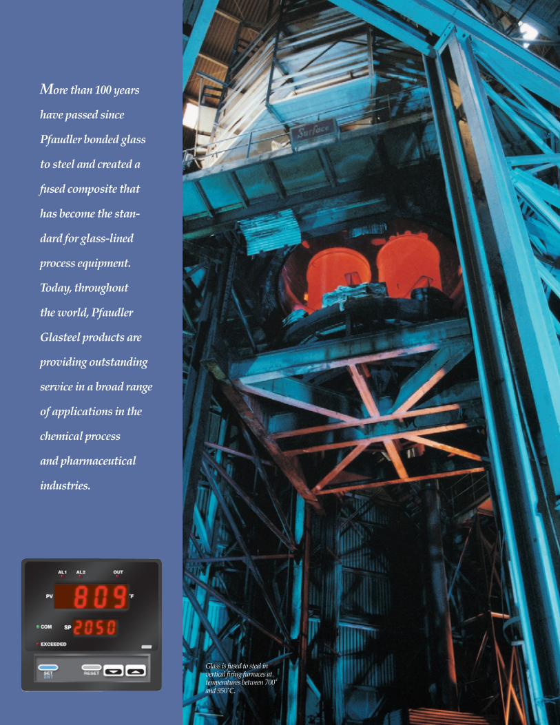
More than 100 years
have passed since
Pfaudler bonded glass
to steel and created a
fused composite that
has become the stan-
dard for glass-lined
process equipment.
Today, throughout
the world, Pfaudler
Glasteel products are
providing outstanding
service in a broad range
of applications in the
chemical process
and pharmaceutical
industries.
Glass is fused to steel in vertical firing furnaces at temperatures between 700̊ and 950̊ C.

Why Glasteel?The benefits of Pfaudler glass-lined equipment arewell known:• Glasteel is resistant to most corrosive substances
even under extreme thermal conditions.• Glasteel is essentially inert, so it cannot
adversely affect product purity or flavor.• Glasteel resists the buildup of viscous or sticky
products, which means better heat transfer, less frequent cleaning and higher productivity.
• Glasteel is strong. Fusing glass to steel produces ahigh strength, corrosive resistant composite.
Now, A Glass for the WorldIn recent years, because of the expansion of the chemical process and pharmaceutical industries worldwide and increased concerns for safety andquality control, Pfaudler began investigating new approaches in glass development that would lead to a glass composition that could be made availableto all users of glass-lined equipment.
Together with the chemical process industry andwith the cooperation of Pfaudler divisions aroundthe world, Pfaudler established the criteria for a newcomposition:• Anon-crystalline structure.• Increased resistance to acid and alkali corrosion.• High resistance to impact.• High resistance to thermally induced stresses.• Aformulation that could be easily produced by all
Pfaudler manufacturing plants.
The result is Glasteel 9100, Pfaudler’s first “interna-tional glass,” offering an unmatched combination of corrosion resistance, impact strength, thermalshock resistance, non-adherence and heat transfer efficiency. Now Pfaudler customers, regardless ofwhere their processing operations are located, canpurchase a single glass system and be assured of getting the same high quality worldwide. WithGlasteel 9100, Pfaudler sets a standard the world can depend on.
Technical Data on Glasteel 9100The remainder of this brochure provides technicaldata for Glasteel 9100. In addition to presentingchemical and physical characteristics, this materialdescribes performance under various conditions,identifies testing procedures used by Pfaudler researchers and provides a variety of other informa-tion derived from Pfaudler research and experiencein the field, all of which is intended to help the user.
Molten glass is poured intoa sparger during the fritmanufacturing operation.
1

The resistance of Glasteel 9100 to acids, water, alkalis and other chemical solutions is presented in Figure 1. Based on the isocorrosion curve (0.1 mm/year) of a number of hydrous acids and alkalis, it describes in general the resistance ofGlasteel 9100 to these substances. Isocorrosion curvesfor specific acid and alkali solutions are included in the sections that follow.
AcidsOutstanding acid resistance under extreme process conditions is a primary characteristic ofGlasteel 9100. In the charts that follow, we present
isocorrosion curves for acids most commonly usedin the chemical industry: hydrochloric, sulfuric, nitric, phosphoric and acetic.
These curves are the result of a test procedure that includes a parameter especially pertinent to glass-lined equipment in service, i.e. the ratio between liquid volume and the glass surface area. The test conditions according to DIN1 51174 (see Test Conditions section on page 8) meet this requirement.
˚C
300
200
100
00 1 2 3 4 5 6 7 8 9 10 11 12 13 14
Characteristic Resistance Curves
Not Resistant
Fully Resistant
Resistant Within Limits
Not Resistant
Acid Alkaline
HydrousBase
HydrouspH Acid (H2O)
Acids
%HCl by WeightVolume to Surface Area Ratio (V/O)=20
200
180
160
140
120
10010 20 30
HClHydrochloric Acid
˚C
0.02 mm/year250ppm SiO2
SiO2 Inhibition
0.5 mm/yr
0.2 mm/yr
0.1 mm/yrFully Resistant
%HNO3 by WeightVolume to Surface Area Ratio (V/O)=20
200
180
160
140
120
10020 40 60
HNO3
Nitric Acid
˚C
0.02 mm/year250ppm SiO2
SiO2 Inhibition
0.5 mm/yr
0.2 mm/yr
0.1 mm/yrFully Resistant
Figure 1. Characteristic resistance curves for acid and alkaline solutions(isocorrosion curve 0.1 mm/year and 0.2 mm/year.)
Boiling point test apparatus is used to determine glass
corrosion resistance in acid and water
environments.
Isocorrosion Curves for Acids
2
%H2SO4 by WeightVolume to Surface Area Ratio (V/O)=20
220
180
140
10020 40 60 80 100
H2SO4
Sulfuric Acid
˚C
0.02 mm/year250ppm SiO2
SiO2 Inhibition
0.5 mm/yr
0.2 mm/yr
0.1 mm/yrFully Resistant
1DIN: Deutsche Industrie Norm.
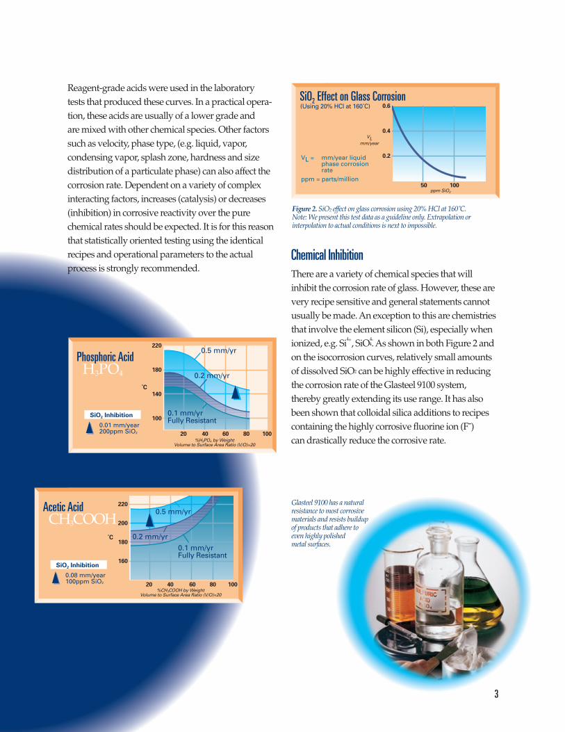
Reagent-grade acids were used in the laboratory tests that produced these curves. In a practical opera-tion, these acids are usually of a lower grade and are mixed with other chemical species. Other factorssuch as velocity, phase type, (e.g. liquid, vapor, condensing vapor, splash zone, hardness and sizedistribution of a particulate phase) can also affect thecorrosion rate. Dependent on a variety of complex interacting factors, increases (catalysis) or decreases(inhibition) in corrosive reactivity over the purechemical rates should be expected. It is for this reasonthat statistically oriented testing using the identicalrecipes and operational parameters to the actualprocess is strongly recommended.
Chemical InhibitionThere are a variety of chemical species that will inhibit the corrosion rate of glass. However, these arevery recipe sensitive and general statements cannotusually be made. An exception to this are chemistriesthat involve the element silicon (Si), especially whenionized, e.g. Si4+, SiO4-
4. As shown in both Figure 2 andon the isocorrosion curves, relatively small amountsof dissolved SiO2 can be highly effective in reducingthe corrosion rate of the Glasteel 9100 system, thereby greatly extending its use range. It has alsobeen shown that colloidal silica additions to recipes containing the highly corrosive fluorine ion (F-) can drastically reduce the corrosive rate.
%CH3COOH by WeightVolume to Surface Area Ratio (V/O)=20
20 40 60 80 100
CH3COOHAcetic Acid
˚C
0.08 mm/year100ppm SiO2
SiO2 Inhibition
0.5 mm/yr
0.2 mm/yr
0.1 mm/yrFully Resistant
220
200
180
160
%H3PO4 by WeightVolume to Surface Area Ratio (V/O)=20
220
180
140
100
20 40 60 80 100
H3PO4
Phosphoric Acid
˚C
0.01 mm/year200ppm SiO2
SiO2 Inhibition
0.5 mm/yr
0.2 mm/yr
0.1 mm/yrFully Resistant
SiO2 Effect on Glass Corrosion
VL = mm/year liquidphase corrosionrate
ppm = parts/million
(Using 20% HCl at 160˚C)
ppm SiO2
0.6
0.4
0.2
50 100
VLmm/year
Figure 2. SiO2 effect on glass corrosion using 20% HCl at 160˚C. Note: We present this test data as a guideline only. Extrapolation or interpolation to actual conditions is next to impossible.
Glasteel 9100 has a natural resistance to most corrosive materials and resists buildup of products that adhere to even highly polished metal surfaces.
3
4
WaterPure WaterPure water in the liquid phase is not very aggressive.Its behavior resembles highly diluted acid and corrodes only the surface layer of the glass (“ion exchange process”). At 170°C, a corrosion rate of 0.1 mm/year can be expected.
But because this water is an unbuffered, pH-unstablesystem, even a slight alkalization can change the situation. If there is a shift toward higher pH values,the isocorrosion curves for diluted alkaline solutionshave to be consulted for orientation purposes.
Glasteel 9100 is highly resistant to condensing watervapor. However, to counter the possible danger ofthe condensate shifting to an alkaline pH, it is recom-mended that the vessel contents be slightly acidifiedwith a volatile acid, e.g. hydrochloric or acetic acid. It is also highly recommended that the unjacketedtop head be insulated or heat traced to reduce condensation formation.
Aqueous Neutral pH MediaWith these type media, e.g. tap water, salt solutions, corrosion rate depends greatly on the type and quantity of the dissolved substance.Carbonates and phosphates usually increase the rate while alcohols and some ionic species, e.g. Al3+, Zn2+ Ca2+, may reduce it.
AlkalisAs alkali concentration rises, corrosion rate increases. Also, the temperature gradient for alkaline glass corrosion is steeper. The result is that concentrated alkalis require a more definite setting of the temperature limits.
The corrosion rate of concentrated alkaline solutions cannot be expressed by the pH value alone. For aqueous solutions of alkaline materialswith a pH value of 14, the particular concentrationmust also be considered to establish appropriate operating temperatures. Other factors affecting alkaline corrosion are the specific reaction and thedissolving ability of the chemical, the influence of thenature and amount of other dissolved substancesand agitation.
Isocorrosion curves are presented on page 5 forsodium hydroxide, potassium hydroxide, sodium
carbonate and ammonia. They take into accounttechnically relevant parameters influencing the rate of corrosion; for example, the volume/surface area ratio, inhibition effects by calciumions, alkaline concentration and temperature.
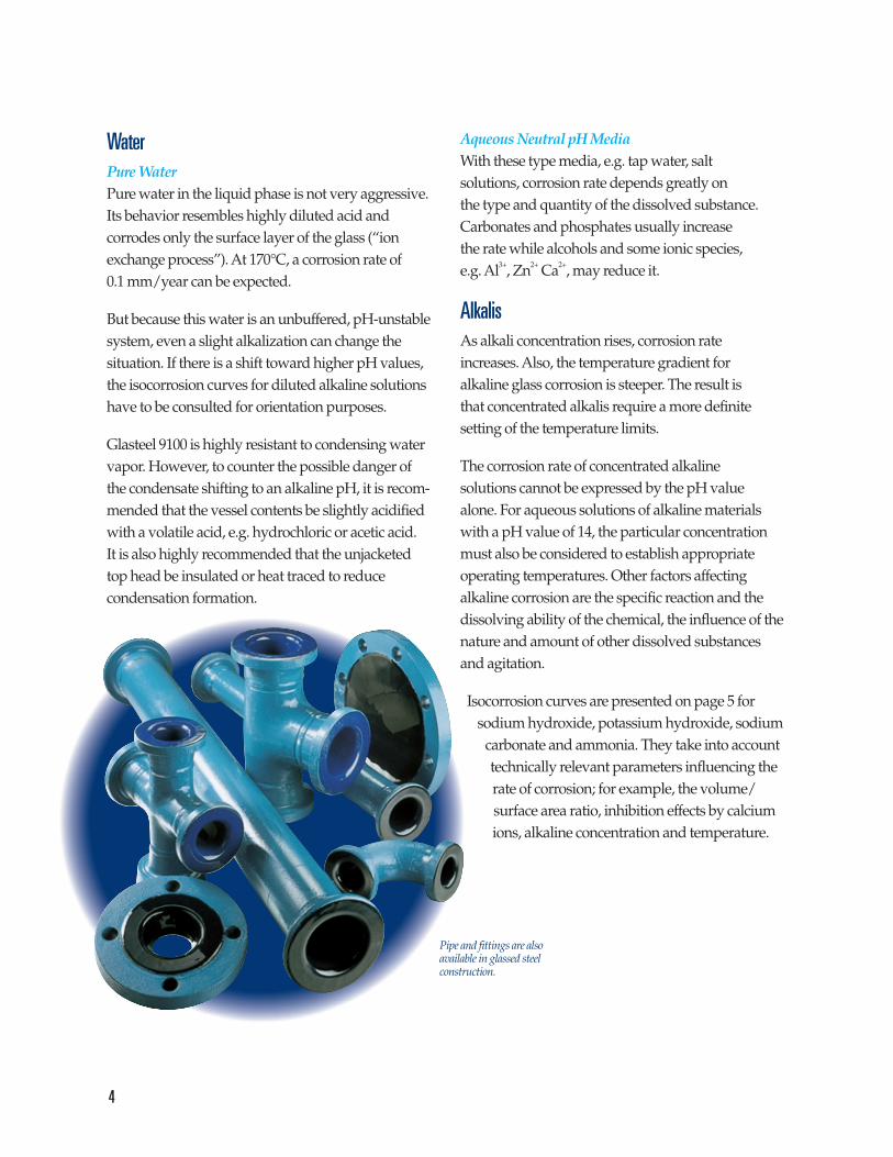
Pipe and fittings are alsoavailable in glassed steelconstruction.

The information in the graphs is based on pure alkaline solutions. Under actual operating condi-tions, even very slight contamination (tap water insodium hydroxide, for example) can cause majorchanges in the rate of corrosion. Other factors, such as product velocity and splash zone, can affect thecorrosion rate as well. Due to these interactive complexities, meaningful testing is strongly advised.
To eliminate the influence of the testing equipmenton the rate of corrosion, procedures were carried outin polypropylene bottles. For solutions above theboiling point, autoclaves with PTFE inserts wereused. By comparing the results with control experi-ments, it was proven that the testing equipment didnot have an inhibiting effect.
Other ChemicalsTable 1 provides general information on theresistance of Glasteel 9100 to some other chemicalsubstances. The data is based on practical experienceand laboratory tests.
NOTE: Pfaudler provides this information withoutobligation, and we do not claim it is complete. Westrongly recommend testings for any exposure notlisted in Table 1, especially for combinations of chemicals. Pfaudler also recommends performingcorrosion tests or contacting Pfaudler even for thoseconditions listed, as details of individualizedprocesses may accelerate or inhibit corrosion.
5
0.5 mm/yr
0.2 mm/yr
0.1 mm/yrFully Resistant
%Na2CO3 by WeightVolume to Surface Area Ratio (V/O)=20
Na2CO3
Sodium Carbonate
˚C
120
100
80
60
400.001 0.01 0.1 100.5 5
10 11 12pH
1
120
100
80
60
0.5 mm/yr
0.2 mm/yr
0.1 mm/yearFully Resistant
%NH3 By WeightVolume to Surface Area Ratio (V/O)=20
NH3
Ammonia
˚C
0.001 0.01 0.1 100.5 510.05
10 11 12 pH13
20
40
%KOH by WeightVolume to Surface Area Ratio (V/O)=20
KOHPotassium Hydroxide
˚C
1200.5 mm/yr
0.2 mm/yr
0.1 mm/yrFully Resistant
10 11 12 13 14 pH
100
80
60
400.0001 0.001 0.01 0.1 100.50.05 51 20
Isocorrosion Curves for Alkalis
%NaOH By WeightVolume to Surface Area Ratio (V/O)=20
0.0001
NaOHSodium Hydroxide
˚C
120
100
80
60
0.001 0.01 0.1 100.50.05 5
0.5 mm/yr
0.2 mm/yr
0.1 mm/yrFully Resistant
10 11 12 13 14 pH
1 20
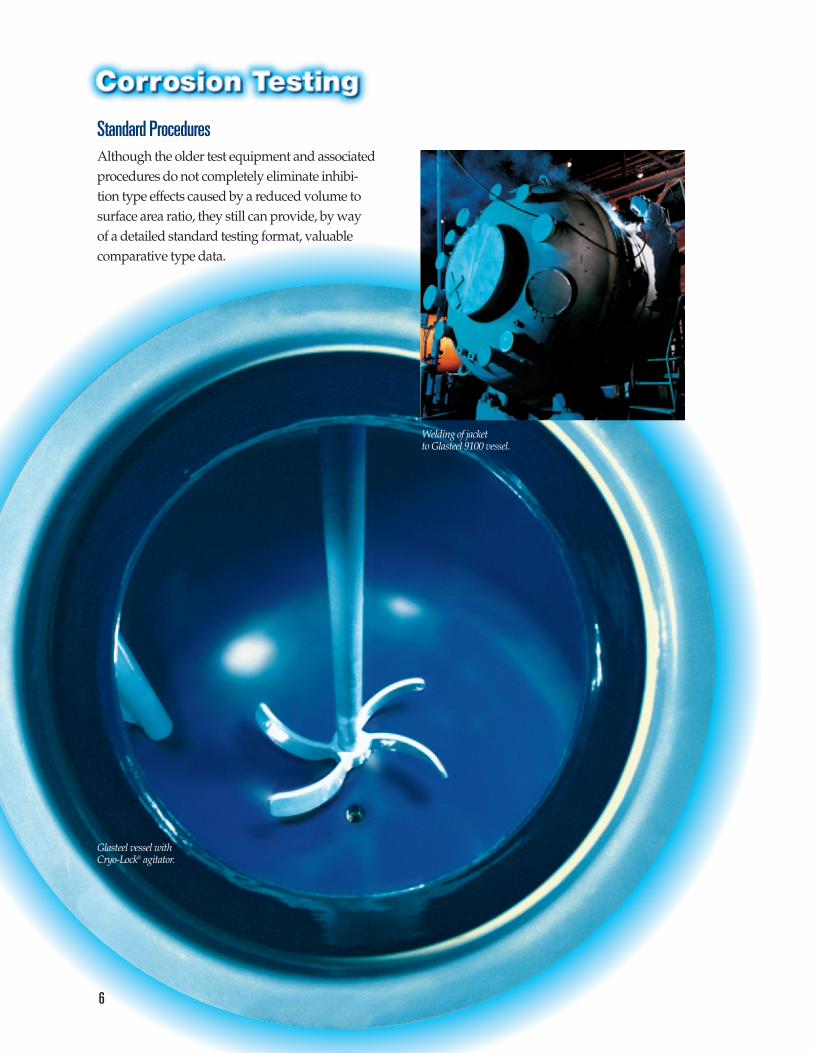
Standard ProceduresAlthough the older test equipment and associatedprocedures do not completely eliminate inhibi-tion type effects caused by a reduced volume to surface area ratio, they still can provide, by way of a detailed standard testing format, valuable comparative type data.
6
Glasteel vessel withCryo-Lock® agitator.
Welding of jacket to Glasteel 9100 vessel.
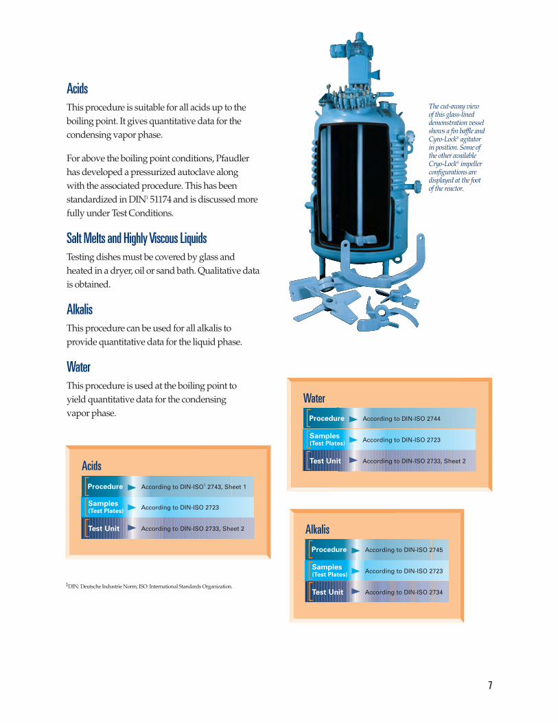
AcidsThis procedure is suitable for all acids up to the boiling point. It gives quantitative data for the condensing vapor phase.
For above the boiling point conditions, Pfaudler has developed a pressurized autoclave along with the associated procedure. This has been standardized in DIN1 51174 and is discussed morefully under Test Conditions.
Salt Melts and Highly Viscous LiquidsTesting dishes must be covered by glass and heated in a dryer, oil or sand bath. Qualitative data is obtained.
AlkalisThis procedure can be used for all alkalis to provide quantitative data for the liquid phase.
WaterThis procedure is used at the boiling point to yield quantitative data for the condensing vapor phase.
7
Alkalis
According to DIN-ISO 2745Procedure
Samples(Test Plates)
Test Unit
According to DIN-ISO 2723
According to DIN-ISO 2734
Water
According to DIN-ISO 2744Procedure
Samples(Test Plates)
Test Unit
According to DIN-ISO 2723
According to DIN-ISO 2733, Sheet 2Acids
Samples(Test Plates)
Test Unit
According to DIN-ISO 2723
According to DIN-ISO 2733, Sheet 2
According to DIN-ISO1 2743, Sheet 1Procedure
The cut-away view of this glass-lineddemonstration vesselshows a fin baffle andCyro-Lock® agitator in position. Some of the other available Cryo-Lock® impellerconfigurations are displayed at the foot of the reactor.
1DIN: Deutsche Industrie Norm; ISO: International Standards Organization.

8
Practical Scale Corrosion TestingFor safety reasons, we need to know the maximumpossible attack of a pure acid on glass coatings.Inhibiting influences, therefore, must be excluded.
In the last few years, however, when glass-lined vessels were increasingly used at the limits of theirranges, Pfaudler tracked down a phenomenon that is also of major importance in connection withcorrosion in the vessel: the ratio between liquid volume and glass surface area. The graph in Figure 3 shows how this ratio changes with the size of the vessel. This new understanding required a new set of test conditions for practical corrosion testing.
Test Conditions (DIN1 51174)Under the new test conditions, very small dumbbell shaped immersion samples, completelycoated with glass so as to precisely determine theweight loss, are exposed to reagent-grade acids for 24 hours. These samples have a glass-lined surface area of 11 or 25 cm2, depending on the type of dumbbell used. They are immersed in large acid volumes (500 ml) in autoclaves with a tantalum lining to prevent any SiO2 inhibition.
The isocorrosion curves shown for hydrochloric acid,sulfuric acid, nitric acid, phosphoric acid and aceticacid, were obtained under these severe conditions.
In addition to the glass coating, other components ofthe system, e.g. repairs or seals, must be carefullyevaluated for suitability as they may have lower resistivities.
Liquid Volume/Glass SurfaceArea Ratio with Vessel Filled
60
40
20
5 10 15 20
Product Volume V (m3)
Volu
me/
Sur
face
Are
a(m
l/cm
2 )
Figure 3. Liquid volume/glass surface area ratio(V/O) with vessel filled.
White Glasteel9100 with bluecalibration lines.
1DIN: Deutsche Industrie Norm;
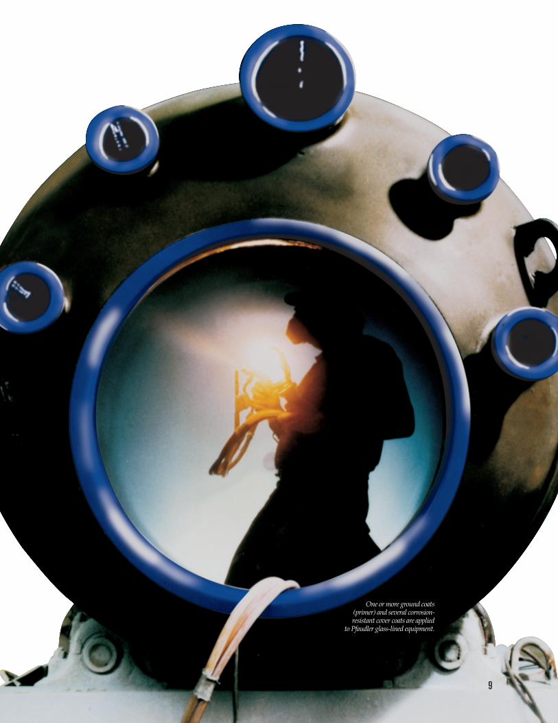
One or more ground coats (primer) and several corrosion-resistant cover coats are applied
to Pfaudler glass-lined equipment.
9

10
AGENT CONC. ˚C RESISTANCE AGENT CONC. ˚C RESISTANCE
A
B
C
Table 1.Resistance of Worldwide Glasteel 9100 to Chemical SubstancesThis data is provided as a ready reference for those in the chemical and pharmaceutical industries.
acetic acid – – sp3acrylic acid i 150 1aluminum acetate melt 200 1aluminum chlorate w 110 1aluminum chloride 10%w bp 1aluminum potassium sulfate 50%w 120 1aminoethanol i 170 1m-aminophenol i 150 1aminophenol sulfonic acid i 130 1ammonia – sp5ammonium-carbonate w bp 1ammonium chloride 10%w 150 1ammonium nitrate w bp 1ammonium phosphate w bp 1ammonium sulfate w bp 1ammonium sulfate w 320 3ammonium sulfide melt 80 1ammonium sulfide w 140 3aniline 100 184 1antimony (III) chloride w 220 1antimony (V) chloride 100 150 1aqua regia 100 150 1
barium hydoxide w bp 2barium sulfate w 150 1benzaldehyde 100 150 1benzene – – 2benzoic acid i 150 1benzyl chloride 100 130 1boric acid w 150 1boron trifluoride ether complex – – 2bromine w 100 1butanol 100 140 1
calcium chloride (free of CaO) w 150 1carbon dioxide w 150 1carbon dioxide w 250 1carbon disulfide 100 200 1carbon tetrachloride 100 200 1chloride bleaching agent w 150 1chlorinated paraffin i 180 1chlorine vapor 200 1chlorine water w 180 1chlorosulfonic acid 100 150 1chlorpropionic acid w 175 1chromic acid 30%w 100 1chromic acid w 150 1chromic sulfuric acid w 200 1citric acid 10%w bp 1cupric chloride 5%w 150 1cupric nitrate 50%w 100 1cupric sulfate w 150 1
D
E
F
G
H
I
L
cyano acetic acid w 100 1cyanoacetamide i 100 1
o, m-dichlorobenzene 100 220 1dichloro-acetic acid w 150 1dichloro-propionic acid 100 175 1diethylamine 100 100 1diethylamino-propanol 100 150 1diethyl ether 100 100 1dimethylamino-propanol 100 150 1dimethyl sulfate 100 150 1
ethyl acetate 100 200 1ethyl alcohol 100 200 1ethylene diamine 98%w 80 1
fatty acid diethanolamide i 105 1fatty acids i 150 1ferric chloride 10%w bp 1ferric (II) chloride w 150 1ferric (III) chloride w 150 1fluoride in aqu. acid sol. – – 2formaldehyde 100 150 1formic acid 98%w 180 1fumaric acid i 150 1
gallic acid i 100 1glutamic acid i 40 1glycerine 100 100 1glycol 100 150 1glycolic acid 57%w 150 1
heptane – – 2hexane – – 2hydrazine hydrate 80%w 90 1hydrazine hydrate 40%w 90 1hydrazine sulfate 10%w 50 1hydrochloric acid – – sp2hydrogen peroxide 30%w 70 1hydrogen sulfide w 150 1hydroiodic acid 20%w 160 1hydroiodic acid 60%w 130 1
iodine i 200 1iron sulfate w 150 1isoamyl alcohol 100 150 1isopropyl alcohol 100 150 1
lactic acid 95%w bp 1lead acetate w 300 1lithium chloride 4%w 80 2lithium chloride 30%w bp 2

AGENT CONC. ˚C RESISTANCE AGENT CONC. ˚C RESISTANCE
11
M
N
O
P
S
T
WU
XZ
lithium hydroxide conc. w 80 3
magnesium carbonate w 100 1magnesium chloride 30%w 110 1magnesium sulfate w 150 1maleic acid w 180 1methanol 100 200 1methyl ester of
o-hydroxy-benzoic acid i 150 1monochloracetic acid w bp 1
naphthalene melt 215 1naphthalene sulfonic acid w 180 1nitrogen oxides w 200 1nitrobenzene 100 150 1nitric acid – – sp2
octanol 100 140 1o-hydroxy-benzoic acid w 150 1oleum (10% SO3) 170 1ortho chlor-benzoic acid w 250 1oxalic acid 50%w 150 1
palmitic acid i 110 1perchloric acid 70%w bp 1perfluoro cyclic ether, anhydrous – – 2phenol 100 200 1phenolphthalein i 100 1phosphoric acid – – sp3phosphoric ethyl ester 100 90 1phosphorous acid (F-free) w 80 1phosphorous acid (F-free) w 100 2phosphorous oxychloride (F-free) w 110 1phosphorous trichloride (F-free) 100 100 1phthalic anhydride i 260 1picric acid i 150 1poly phosphoric acid w 140 1potassium bisulfate melt 200 1potassium bromide w bp 1potassium chloride w bp 1potassium hydroxide – – sp5pyridine 100 bp 1pyridine chloride i 150 1pyridine hydrochloride i 150 1pyrogallic acid 5%w bp 1pyrrolidine 100 90 1
sodium bicarbonate w bp 2sodium bicardonate, 1N w 95 1sodium biphosphate 50%w bp 1sodium bisulfate w 300 1
sodium bisulfite 2%w 150 1sodium carbonate – – sp5sodium chlorate w 80 1sodium chloride w bp 1sodium ethylate i bp 1sodium fluoride – – 2sodium glutamate w 150 1sodium hydroxide – – sp5sodium hypochloride w 70 1sodium methylate i 90 1sodium nitrate w 320 1sodium sulfide 4%w 50 2stearic acid i 160 1succinic acid w 200 2sulfur i 150 1sulfur dioxide w 200 1sulfuric acid – – sp2
tannic acid w 150 1tartaric acid w 140 1tetrachloroethylene 100 150 1tin chloride w 250 1toluene – – 2trichloro-acetic acid w 150 1triethanolamine w 250 1triethylamine 30%w 80 1triethylamine w 130 3trifluoracetic acid, anhydrous – – 2trimethyl-amine 30%w 80 1trisodium phosphate 50%w 80 1trisodium phosphate 5%w bp 2
urea i 150 1
water – – sp2
o, m, p xylenes – – 2
zinc bromide w bp 1zinc chloride melt 330 1zinc chloride w 140 1
Legend1 Good resistance
2 Contact Pfaudler
3 Not resistant
i All concentrations up to saturation in aninert solvent
w All concentrations up to saturation in water,unless otherwise noted
bp boiling point
sp See page (of this brochure)

-100 -50 0 50 100 150 200 250
Vessel Side
Tem
pera
ture
of
Reacta
nts
(˚C
)
Lower temperaturelimits depend oncode and thickness*
*ASME Code limitslow temperature to-29˚C for under25mm (1 inch)thickness onstandard design.DIN Standard limitslow temperature to-60˚C on standarddesign.
250
HeatingCooling
200
150
100
0
-100
Wall Temperature (˚C)
50
-50
ASME
DIN
Temperature LimitsAlthough Pfaudler glasses are modified to makethem adhere to steel, and the firing process incorpo-rates helpful compressive stresses in the glass layer,they are prone to excessive thermal stresses. Thereare definite limits beyond which damage can occur.
“Safe” operating temperatures vary with conditions.Because so many variables are involved, temperatureranges are given only as a guide for standard vessels,including those with half-pipe jackets. Operationbelow the maximum temperature and above theminimum is strongly recommended.
Only two conditions must be considered when deter-mining the temperature limits of a Glasteel vessel:A. Introduction of reactants into a vessel.B. Introduction of media into a jacket.
The limits for condition Aare determined from Chart A; those for condition B from Chart B.
In both cases, the safe operating range lies within the polygons as outlined on the charts. Wall tempera-ture is plotted on the horizontal axes of both charts;
Reactant Temperature (Chart A) and JacketTemperature (Chart B) on the vertical axes.
With Chart B, it is also necessary to know the heattransfer film coefficient of the jacket media. Threecurves are shown: one for steam (8500 W/m2K) andtwo for typical heating oils (1500 and 1000 W/m2K).
Operating Temperature: Practical Examples
Example 1.Determine the maximum and minimum allowable wall temperatures of a vessel when introducing reactants at 100°C into the vessel.
Procedure. Since the reactants are being introduced into the vessel, Chart A applies. Find the temperature of 100°C on the reactants temperature axis. If you followthis constant temperature along the wall temperature axis,you will see it intersects the polygon at wall temperaturesof -30°C (ASME vessel) and -60°C (DIN vessel) at thelower temperature end and at 210°C at the upper temperature end.
Answer. Reactants at 100°C can be introduced safe-ly into a vessel whose wall temperature is between-30°C ASME/-60°C DIN and 210°C.
12
Chart A

Example 2.Avessel with a wall temperature of 100°C is to be heated using hot oil with a heat transfer film coefficient of 1500W/m2K. What is the maximumtemperature oil that can be used?
Procedure. Since the media is being introduced into the jacket, Chart B applies. Find the wall temperature of 100°C along the wall temperature axis. If you follow this line along the jacket temperature axis, it intersects the oil (1500W/m2K) polygon at a jacket temperature of 257°C.
Answer. The maximum allowable temperature of a1500W/m2K oil introduced into the jacket of a 100°C vessel is 257°C.
Example 3.
Abatch has just been completed and the wall tem-perature of the vessel is 150°C. What are the upperand lower temperature limits of reactants that canbe introduced in the vessel for the next batch?
Procedure. Chart A applies. Find the temperature of150°C on the wall temperature axis. This line
intersects the polygon at reactant temperatures of 0°and 232°C.
Answer. The maximum and minimum temperatures ofreactants that can be introduced into a vessel with a walltemperature of 150°C are 232° and 0°C respectively.
Example 4.
Steam is being used to heat reactants in a vessel.The vessel contents are at 125°C. Can steam at250°C be introduced into the jacket?
Procedure. Chart B applies. The intersection of a wall temperature of 125°C and a jacket temperature of 250°C is outside the steam polygon on the chart.
Answer. Steam at 250°C cannot be introduced safely into a vessel whose contents are at 125°C.
CAUTION: While pressure loads are included in the Charts, other mechanical stressing effects, (e.g.nozzle loadings) are not. Since most of these stresstype loads are additive, a combined loading analysismust be done and the appropriate safety factors in-corporated. Contact Pfaudler for further information.
13
-100 -50 0 50 100 150 200 250
Jacket Side
Tem
pera
ture
of
Jacket
Med
ia (
˚C)
Lower temperaturelimits depend oncode and thickness*
*ASME Code limitslow temperature to-29˚C for under25mm (1 inch)thickness onstandard design.DIN Standard limitslow temperature to-60˚C on standarddesign.
400
HeatingCooling
300
200
100
0
-100
Wall Temperature (˚C)
ASME
DIN
Oil (1000 W/m2K)Oil (1500 W/m2K)
Steam
Chart B
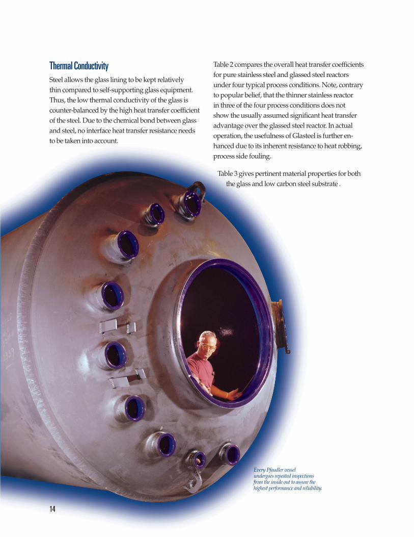
Thermal ConductivitySteel allows the glass lining to be kept relatively thin compared to self-supporting glass equipment.Thus, the low thermal conductivity of the glass iscounter-balanced by the high heat transfer coefficientof the steel. Due to the chemical bond between glassand steel, no interface heat transfer resistance needsto be taken into account.
Table 2 compares the overall heat transfer coefficientsfor pure stainless steel and glassed steel reactorsunder four typical process conditions. Note, contraryto popular belief, that the thinner stainless reactor in three of the four process conditions does not show the usually assumed significant heat transferadvantage over the glassed steel reactor. In actual operation, the usefulness of Glasteel is further en-hanced due to its inherent resistance to heat robbing,process side fouling.
Table 3 gives pertinent material properties for boththe glass and low carbon steel substrate .
Every Pfaudler vessel undergoes repeated inspectionsfrom the inside out to assure thehighest performance and reliability.
14

Glasteel 9100 dual flight Cryo-Lock®
agitator to improvemixing.
Table 2.Heat Transfer Coefficients
Table 3.Material Properties for Glass and Low Carbon Steel
Property Glass Low Carbon Steel
Adhesion >100 N/mm2
–(Glass on steel) (14.5 x 10³ lb/in2)
Compressive strength800 - 1000 N/mm2 ~240 N/mm2
(11.6 - 14.5 x 10⁴ lb/in2) (~34.5 x 10³ lb/in2)
Density2.5 g/cm3 7.8 g/cm3
(0.09 lb/in3) (0.28 lb/in3)
Dielectric strength20 - 30 kv/mm
(508 - 762 v/mil)
Elongation 0.1% 15 - 35%
Glass thickness, average1 - 2 mm
–(39 - 79 mils)
Hardness600 Vickers 100 Vickers
(5.5 Mohs scale) (62 HRB)
Linear coefficient of expansion 88 x 10-7/C 136 x 10-7 /C20˚ -400˚C (49 x 10-7 /F) (76 x 10-7 /F)
Modulus of elasticity75,000 N/mm2 210,000 N/mm2
(10.9 x 10⁶ lb/in2) (30.5 x 10⁶ lb/in2)
Softening temperature 570˚C (1058˚F) –
Specific electrical resistance (R.T.) 1012 - 1014 ohm-cm 12 x 10-6 ohm-cm
Specific heat835 J/kg K 460 J/kg K
(0.2 BTU/lb˚F) (0.11 BTU/lb˚F)
Surface resistance(R.T., 60% RH)
5 x 10⁹ ohms –
Surface roughness0.08 - 0.18 micrometers –(3.1 - 7.1 microinches) –
Tensile strength70 - 90 N/mm2 380 - 515 N/mm2
(10.2 - 13.1 x 10³ lb/in2 (55 - 75 x 103 lb/in2)
Thermal conductivity1.2 W/mK 52W/mK
(6.9 BTU - in/hr ft2 ˚F) (360 BTU - in/hr ft2 ˚F)
Overall Heat Transfer Coefficient (Service U)* W/m2K**
Material of Construction Heating Water Heating Water Cooling Cooling Viscous(Barrier Material) with Steam with Heat Organic Liquid Organic Liquid
Transfer Oil with Water with Water
Stainless reactor512 353 199 950.656 in. (16.7 mm) wall✝
Glasteel reactor, 0.05 in. (1.3 mm) glass 437 316 185 940.688 in. (17.5mm) steel✝
Combined film conductance,
1703 778 284 114hi hohi+ho
* Fouling factors typical to process fluids and materials of construction are included.** Divide by 5.678 for conversion to BTU/hr ft2 -˚F.✝ Thickness based on 1,000-gallon reactors for service at same pressures.
15

CavitationThe introduction of steam into liquids of lower temperature can result in the rapid collapse of thebubbles through condensation. This collapse, termedcavitation, can result in a considerable energy release.If this release occurs near or at the surface of the glass,an impact type damage may result. Cavitation typeproblems may also occur due to the exothermicvolatilization of a low boiling reactant with bubblecollapse effected by condensation, pressure buildupor kinetic reaction. The partial vacuum created on the backside of an agitator blade can also cause formation of low boiling vapor bubbles that maycollapse as they move to higher pressure regions.Consult Pfaudler for further information.
Electrostatic DischargeLiquid organic media usually do not pose chemicalresistivity problems for Glasteel. However, materialsthat possess low specific conductivities, e.g. hexane,the xylenes, toluene, benzene, heptane, either aloneor in combination with other liquids, solids and/orvapor phases, may lead to an electrostatic dischargewithin the liquid, between the liquid and vapor, orbetween the liquid/vapor and the vessel walls or accessories. Note that this discharge can occureven in a grounded metal vessel. Addition of staticsensitive powders through a nozzle may also presenta problem.
The electrostatic discharge could ignite a flammablevapor in a poorly inerted atmosphere, harm instru-mentation or produce a pinhole type dielectric break-down of the protective Glasteel glass coating.
If these type problems are existent or anticipated,professionals in the area of electrostatics shouldbe consulted.
Abrasion ResistanceGlasteel coatings are sufficiently hard (600 Vickers) to provide excellent resistance to abrasive wear.
The abrasion resistance of the glass lining by part-iculates is dependent on the hardness, shape, size distribution and concentration of the particles, aswell as the characteristics of the liquid medium, e.g. polarity.
Testing must be done under actual conditions to ensure serviceability.
Glasteel 9100 offers the best combination of abrasion-corrosion resistance available to the chemical processing industry today.
Abrasion resistance has been measured using both the ASTM abrasion test C448 and the DIN test 51152.
The results were: ASTM = 3.9± 0.3 mg/cm2-hr; DIN = 2.5 mg/cm2-hr.
Pfaudler makes a glass for your applicationIn addition to Worldwide Glasteel 9100, Pfaudler offers a wide variety of unique glasses to meet special requirements such as these:• Elevated Operating Temperatures• Glass Coatings for Austenitic Stainless Steels• Higher Alkali Resistance• Increased Resistance to Thermal Stress• Reduced Polymer Adherence
For solutions to these challenges and others at yourlocation, contact Pfaudler.
16

21
The Numbering System for Pfaudler GlassesMany of the people reading thisbrochure have had or will have an opportunity to order glass-lined equipment from Pfaudler. To assist you in that process and help you better understand how our glass identification system works, the following decoding informationis offered:
Pfaudler glasses are identified by a four-digit number also used for ordering purposes. The first two digits represent the glass system. For example, 91 indicates the 9100 Series of glasses. However, you cannotsimply order 9100; you must also specify the third and fourth digits.
The third digit represents color:
1 = Dark Blue
2 = White
3 = Green
4 = Light Blue
9 = All Other
The fourth digit represents factoryDC test voltage permutations:
1 = Visual, no test voltage
2 = 5,000 Volts
3 = 7,000 Volts
4 = 12,000 Volts
5 = 15,000 Volts
9 = Any non-standard test condition
For example, an order for Pfaudler 9115 glass indicates our 9100 Series glass in Dark Blue with a test rating of 15,000 volts. Your Pfaudler represen-tative will assist you in identifying theproper specification number for yourparticular order.

SB95-910-5
The information contained in this bulletin is believed to be reliable general guidelines for considera-tion of the products and services described herein. The information is general in nature and should not be considered applicable to any specific process or application. Pfaudler, Inc. and Glasteel® Parts andServices expressly disclaim any warranty, expressed or implied, of fitness for any specific purpose in connection with the infor-mation contained herein.
US Facilities
Pfaudler, Inc.Rochester, New YorkTel: (1 716) 235-1000Fax: (1716) 235-6393
Glasteel® Parts and ServicesRochester, New YorkTel: (1 716) 235-1010Fax: (1 716) 235-7923
Worldwide Facilities
Chemical Reactor Services Ltd.Bolton, EnglandTel: (44 1204) 862-777Fax: (44 1204) 577-484
Bilston, EnglandTel: (44 1902) 353-637Fax: (44 1902) 495-696
GMM PfaudlerBombay, IndiaTel: (9122) 2047470Fax: (9122) 2049408
Pfaudler-Balfour Ltd.Leven, Fife, ScotlandTel: (44 1333) 423-020Fax: (44 1333) 427-432
Pfaudler EquipamentosIndustriais Ltda.Taubate, SP, BrazilTel: (55 122) 326-244Fax: (55 122) 217-562
Pfaudler S.A. de C.V.Mexico City, MexicoTel: (52 5) 355-0100Fax: (52 5) 355-0809
Pfaudler-Werke GmbHSchwetzingen, GermanyTel: (49 620) 2850Fax: (49 620) 222412
Suzhou Pfaudler Glass-Lined EquipmentCompany Ltd.Suzhou, ChinaTel: (86 512) 534 1622Fax: (86 512) 534 0870
1000 West AvenuePO Box 23600Rochester, NY 14692-3600Tel: 716 235 1000Fax: 716 235 6393www.pfaudler.com
1999 Mt. Read Blvd.PO Box 20857Rochester, NY 14602Tel: 716 235 1010Fax: 716 235 7923
Copyright ©Pfaudler, Inc. 2000A Unit of Robbins & Myers, Inc.All rights reserved
Glasteel® and Cryo-Lock® are registered trademarks of Pfaudler, Inc.1/00 3M Mech No. 549
Pfaudler, Inc.Rochester, New York
Glasteel® Parts and ServicesRochester, New York
Pfaudler S.A. de C.V.Mexico City, Mexico
Pfaudler EquipamentosIndustriais Ltda.Taubate, SP, Brazil
Pfaudler-Balfour Ltd.Leven, Scotland
Chemical Reactor Services, Ltd.Bolton, EnglandBilston, England
Pfaudler-Werke GmbHSchwetzingen, Germany
GMM PfaudlerBombay, India
Suzhou Pfaudler Glass-Lined EquipmentCompany Ltd.Suzhou, China