WORLDWIDE General Specification ENGINEERING … 3097-2006.pdfGeneral Specification ......
34
WORLDWIDE ENGINEERING STANDARDS General Specification Electrical/Electronic GMW3097 General Specification for Electrical/Electronic Components and Subsystems, Electromagnetic Compatibility © Copyright 2006 General Motors Corporation All Rights Reserved July 2006 Originating Department: North American Engineering Standards Page 1 of 32 1 Introduction Note: In the event of a conflict between the text of this specification and the documents cited herein, the text of this specification takes precedence. Note: Nothing in the specification supersedes applicable laws and regulations unless a specific exemption has been obtained. 1.1 Scope. This document applies to the Electromagnetic Compatibility (EMC) of electrical/electronic components and subsystems for passenger vehicles, light duty trucks and medium duty trucks. This document is one out of a series of three global EMC documents, which specify EMC test and validation requirements. The complete series consists of the following documents: GMW3091, GMW3097 and GMW3103 (All three documents of equal revision carry the same release date). Note: Earlier versions of GMW12559, GMW12002V, GMW12002R, and GMW3100, have been integrated into GMW3097 for ease of use. 1.2 Mission/Theme. This document specifies the EMC requirements for all automotive products when evaluated in accordance with the test procedures contained within this document. It refers to International EMC Standards whenever possible, but also describes internal test procedures if necessary. 1.3 Classification. Not applicable. 2 References Note: Only the latest approved standards are applicable unless otherwise specified. 2.1 External Standards/Specifications. IEC CISPR 25 ISO 11452-1 IEC 61000-4-21 ISO 11452-2 ISO 7637-1 ISO 11452-4 ISO 7637-2 ISO 17025 ISO 7637-3 SAE J1113-22 ISO 10605:2001 2.2 GM Standards/Specifications. GMW3059 GMW3103 GMW3089 GMW3122 GMW3091 3 Requirements Validation testing must be performed at a laboratory that has received recognition through the Automotive EMC Laboratory Recognition Program (AEMCLRP). To obtain recognition, a laboratory must provide evidence of: a. ISO 17025 certification to at least the base specifications that apply to GMW EMC test procedures. The base specifications are listed in Table 1. Table 1: AEMCLRP List of Base Specifications Procedure Name Base Specification Radiated Emissions Anechoic IEC CISPR 25 Bulk Current Injection ISO11452-4 Radiated Immunity Anechoic ISO11452-2 Radiated Immunity Reverb IEC 61000-4-21 Transient Immunity ISO7637-2 and ISO7637-3 Electrostatic Discharge ISO10605:2001 b. Demonstrate meeting proficiency test requirements where applicable. This requires testing a defined artifact and comparing results against results obtained at reference laboratory(ies). Comparisons must meet the metrics detailed in the AEMCLRP. Copyright GM Worldwide Provided by IHS under license with GMW Licensee=Visteon Corp/5962532002 Not for Resale, 11/23/2007 02:17:17 MST No reproduction or networking permitted without license from IHS --``,,,,,,````,``,,`,,,,``,`,,,`-`-`,,`,,`,`,,`---
Transcript of WORLDWIDE General Specification ENGINEERING … 3097-2006.pdfGeneral Specification ......

WORLDWIDE ENGINEERING STANDARDS
General Specification Electrical/Electronic
GMW3097
General Specification for Electrical/Electronic Components and Subsystems, Electromagnetic Compatibility
© Copyright 2006 General Motors Corporation All Rights Reserved
July 2006 Originating Department: North American Engineering Standards Page 1 of 32
1 Introduction Note: In the event of a conflict between the text of this specification and the documents cited herein, the text of this specification takes precedence. Note: Nothing in the specification supersedes applicable laws and regulations unless a specific exemption has been obtained. 1.1 Scope. This document applies to the Electromagnetic Compatibility (EMC) of electrical/electronic components and subsystems for passenger vehicles, light duty trucks and medium duty trucks. This document is one out of a series of three global EMC documents, which specify EMC test and validation requirements. The complete series consists of the following documents: GMW3091, GMW3097 and GMW3103 (All three documents of equal revision carry the same release date). Note: Earlier versions of GMW12559, GMW12002V, GMW12002R, and GMW3100, have been integrated into GMW3097 for ease of use. 1.2 Mission/Theme. This document specifies the EMC requirements for all automotive products when evaluated in accordance with the test procedures contained within this document. It refers to International EMC Standards whenever possible, but also describes internal test procedures if necessary.
1.3 Classification. Not applicable.
2 References Note: Only the latest approved standards are applicable unless otherwise specified. 2.1 External Standards/Specifications. IEC CISPR 25 ISO 11452-1 IEC 61000-4-21 ISO 11452-2 ISO 7637-1 ISO 11452-4 ISO 7637-2 ISO 17025 ISO 7637-3 SAE J1113-22 ISO 10605:2001 2.2 GM Standards/Specifications. GMW3059 GMW3103 GMW3089 GMW3122 GMW3091
3 Requirements Validation testing must be performed at a laboratory that has received recognition through the Automotive EMC Laboratory Recognition Program (AEMCLRP). To obtain recognition, a laboratory must provide evidence of: a. ISO 17025 certification to at least the base
specifications that apply to GMW EMC test procedures. The base specifications are listed in Table 1.
Table 1: AEMCLRP List of Base Specifications
Procedure Name Base Specification Radiated Emissions Anechoic IEC CISPR 25 Bulk Current Injection ISO11452-4 Radiated Immunity Anechoic ISO11452-2 Radiated Immunity Reverb IEC 61000-4-21 Transient Immunity ISO7637-2 and ISO7637-3 Electrostatic Discharge ISO10605:2001
b. Demonstrate meeting proficiency test
requirements where applicable. This requires testing a defined artifact and comparing results
against results obtained at reference laboratory(ies). Comparisons must meet the metrics detailed in the AEMCLRP.
Copyright GM Worldwide Provided by IHS under license with GMW Licensee=Visteon Corp/5962532002
Not for Resale, 11/23/2007 02:17:17 MSTNo reproduction or networking permitted without license from IHS
--``,,,,,,````,``,,`,,,,``,`,,,`-`-`,,`,,`,`,,`---

GMW3097 GM WORLDWIDE ENGINEERING STANDARDS
© Copyright 2006 General Motors Corporation All Rights Reserved
Page 2 of 32 July 2006
3.1 Product Characteristics. 3.1.1 Sample Size. A minimum of two (2) samples shall be tested. 3.1.2 Power Supply. The supply voltage shall be 13.5 (+0.5/-1) V, unless otherwise stated in the test plan. 3.2 Performance Requirements. The DUT (Device Under Test) shall pass both the component level tests according to this specification and the vehicle level tests according to GMW3091. Component tests are not intended to take the place of vehicle tests. Exact correlation between component and vehicle test performance is dependent on component mounting location, harness length, routing and grounding, as well as antenna system. Component testing, however, permits components to be evaluated prior to actual vehicle availability. Deviations from the requirements and/or test procedures shall have been agreed upon prior to testing. Such deviating requirements shall be specified in the test plan and on component drawings, test certificates, reports, etc.
Table 2 is supplied as a guide for the selection of the minimum tests applicable to electrical/electronic components and subsystems. The result of following this Table 2 may not be all inclusive. The final list of required tests is to be determined by the EMC Engineer during the GMW3103 process. Note: Any/all EMC test results must be accompanied by a GMW3103 EMC Test Plan (complete with an approval number supplied by the GM EMC Engineer). In this document, electronic modules, electric motors and inductive devices are classified into categories that determine the appropriate test requirements. This category shall be documented in the test plan. For all tests the more stringent requirement applies at frequency breakpoints and overlaps. Additionally, Table 3 contains specific EMC design requirements for some categories of devices which shall be validated by inspection (e.g. no testing required). Compliance to these requirements shall be documented in the test report.
Table 2: EMC Test Selection Matrix
Others Electronic Components Motors
Test Paragraph Numbers
D R A AS AM AX BM EM Emissions
3.3 ALSE
CE, Artificial Network 3.3.1 3.3.2 X X X X X X
Bulk Current Injection Anechoic Chamber
Reverb, Mode Tuning
3.4.1 3.4.2 3.4.3
X X X X X Immunity 3.4
Magnetic Field 3.4.4 X X Note
Conducted Emissions 3.5.1 X X X X CI, Power Lines only 3.5.2 X X X X X
CI, Coupling to I/O Other than Power Supply Lines 3.5.3 X X X X X
CI, Direct Capacitive Coupling to Sensor Lines 3.5.4 X
Transients 3.5
(Optional) CI, 85V Direct Capacitor Coupling 3.5.5 X X X
Powered-On Mode 3.6.1 X X X Remote I/O 3.6.2 X X X ESD
3.6 Handling of Devices 3.6.3 X X X X X X
Note: Applies only to motors with integral Hall Effect sensors.
Copyright GM Worldwide Provided by IHS under license with GMW Licensee=Visteon Corp/5962532002
Not for Resale, 11/23/2007 02:17:17 MSTNo reproduction or networking permitted without license from IHS
--``,,,,,,````,``,,`,,,,``,`,,,`-`-`,,`,,`,`,,`---

GM WORLDWIDE ENGINEERING STANDARDS GMW3097
© Copyright 2006 General Motors Corporation All Rights Reserved
July 2006 Page 3 of 32
Electronic Module Categories:
A A component or module that contains active electronic devices. Examples: analog op amp circuits, switching power supplies, microprocessor controllers and displays.
AM An electronic component or module that contains magnetically sensitive elements.
AS An electronic component or module operated from a regulated power source in another module. This is usually a sensor providing input to a controller.
AX An electronic module that controls an inductive device (e.g. electric or electronically controlled motor(s), solenoids, etc.) internal or external to its package.
D Module containing only diodes and mechanically switched to battery (e.g. LED Center High Mounted Stop Lamp display, Inflator Shut Off Switch)
Electric Motors: BM A brush commutated electric motor. EM A brushless commutated electric motor.
Inductive Devices: R Relays and solenoids and horns
Table 3: Specific EMC Design Validation Requirements for Devices
Others Electronic Components Motors Validation by Inspection Paragraph
Numbers D R A AS AM AX BM EM
Restriction of Motor Capacitance to Control
Switching Transients3.7.1 X X
BM Glass Wipers and HVAC Blower Motor Capacitance
And Diode Transient Voltage Clamp
3.7.2 X Note 1 XNote 1
Package Protection - Short-Duration Motor Inductors 3.7.3 X
Package Protection - Short-Duration BM Motor
Transient Voltage Suppression
3.7.4 X
Package Protection – Transient Voltage
Suppression on AX Outputs Switching BM Motors
3.7.5 X
Specific EMC Design
Requirements 3.7
Communication Bus (Low-Speed GMLAN, High-Speed
GMLAN, etc.)3.7.6 X X X X
Note 1: Transient voltage diode clamp requirement applies to the motor control circuit (e.g. may be installed in the electrical center, the wiring, or the motor itself).
3.2.1 Report. All test reports shall include the following elements in addition to the report elements specified in each section: • Internal unique test report number. • Part number and description of the DUT,
Hardware and Software Version. • Date of test.
• Facility name. • Requesting engineer. • Requesting division/company. • Type of test (Design Validation or Product
Validation).
Copyright GM Worldwide Provided by IHS under license with GMW Licensee=Visteon Corp/5962532002
Not for Resale, 11/23/2007 02:17:17 MSTNo reproduction or networking permitted without license from IHS
--``,,,,,,````,``,,`,,,,``,`,,,`-`-`,,`,,`,`,,`---

GMW3097 GM WORLDWIDE ENGINEERING STANDARDS
© Copyright 2006 General Motors Corporation All Rights Reserved
Page 4 of 32 July 2006
• Test Equipment Software Revision (if test equipment is software controlled).
• Copy of the test plan used to collect the test data (complete with the approval number provided by the GM EMC Engineer).
• DUT Category (from the Test Selection Matrix and as documented in the test plan)
• Any deletion from or addition to the test procedure.
• Description of the test set-up and equipment used.
• Photograph of the test set-up. • Part number and description of the harness. • Equipment calibration data, if required by the
test plan, unless available in the facility records.
Note: All data submitted must be in the format specified in each of the applicable paragraphs of this document. 3.3 Radiated Emissions (RE) and Conducted Emissions (CE). Prior to measurement of the DUT emissions, test setup ambient levels (i.e. load/box, simulator energized without DUT), the ambient levels shall not be above the limit and should be 6 dB below the limit. This data shall be supplied within the test report. Noise is divided into three different types: • Non-spark generated noise: Noise generated
by electronic sources, such as microprocessors, clocks, PWM, etc.
• Combination of non-spark and spark generated noise. This noise contains contributions from a PWM driving a motor and motor brush noise.
• Spark generated noise: Noise generated by sparks, such as ignition systems, short and long duration brush type motors etc.
• For the purpose of this standard, short-duration brush type motors are defined as those motors that cannot operate continuously while driving the vehicle. Examples include window motors, door lock motors, seat adjustment motors, mirror motors, secondary AIR pumps, load-leveling compressors, etc.
• Long (continuous) duration brush type motors are defined as those motors that can operate continuously while driving the vehicle. Examples include engine cooling fans, wipers, fuel pumps, and HVAC blower motors.
The RF spectrum reporting has been divided into individual onboard receiver bands. There is an additional 1% guard band included in the table values for those receiver bands between 30 and
240 MHz. This is to be able to establish risk of emissions “drift”. Emissions that exist within this 1% guard band are to be included in the final report. Emissions may be captured in the individual onboard receiver bands or from 150 kHz to 1583 MHz, or in any other appropriate number of sub bands. The test results should be reported as shown in Appendix CThe Non-Spark requirements of both Table 4 and Table 7 are applicable to the following: • Categories A, AS, AM, EM, AX, AX with EM,
AX with BM (both continuous and short-duration)
The Spark requirements of both Table 5 and Table 8 are applicable to the following: • Categories BM (Continuous), AX with BM
(Continuous) The Spark requirements of both Table 6 and Table 8 are applicable to the following: • Categories BM (Short-Duration), AX with BM
(Short-Duration) The use of a PK detector at greater RBW is allowed as a quick pre-screen in all bands to increase testing efficiency. If the PK emissions are below the appropriate requirement(s) the test data may be submitted as the final result. If the PK emissions are above the requirement(s), it will be necessary to resweep the entire band using the specified bandwidth and detector. Quasi-Peak (QP) detector is typically used for measurement of “Spark” generated emissions. 3.3.1 RE, Absorber Lined Shielded Enclosure (ALSE). 3.3.1.1 Equipment. The test equipment shall comply with the requirements of IEC CISPR 25. Preamplifier/Preselector: Due to the extremely low level signals that must be observed, a preamplifier (or preselector) may be required ahead of the receiver to improve the system sensitivity. 3.3.1.2 Procedure. Below 30 MHz, one DUT orientation (as in the vehicle if known) is required; above 30 MHz three orthogonal DUT orientations are required. The maximum level at each frequency shall be reported. For the frequency range 1 to 2 GHz the receiving antenna shall be moved 0.75 m parallel to the front edge of the ground plane towards the DUT in order to point at the DUT instead of the center of the wiring harness. 3.3.1.3 Requirements. The field strength level of the radiated emissions shall not exceed the levels of Tables 4, 5, and 6.
Copyright GM Worldwide Provided by IHS under license with GMW Licensee=Visteon Corp/5962532002
Not for Resale, 11/23/2007 02:17:17 MSTNo reproduction or networking permitted without license from IHS
--``,,,,,,````,``,,`,,,,``,`,,,`-`-`,,`,,`,`,,`---

GM WORLDWIDE ENGINEERING STANDARDS GMW3097
© Copyright 2006 General Motors Corporation All Rights Reserved
July 2006 Page 5 of 32
Table 4: Radiated Emissions Absorber Lined Chamber (ALSE) Non-Spark Requirements
ID # Region RF Service (User Band)
(MHz)
Frequency Range (MHz)
Conditions Non-Spark
Limit (dBμV/m)
Note
G1 Global Medium Wave /AM 0.53 to 1.71 30 PK
NA1 America DoT I (45.68 to 47.34) 45.2 to 47.8 12 PK 1
G2 Global 4 Meter (66 to 87.2) 62.5 to 88.1 12 PK 1
JA1 Japan FM I (76 to 90) 75.2 to 90.9 12 PK 1
G3 Global FM II (87.5 to 108) 86.6 to 109.1 12 PK 1, 4
G4 Global 2 Meter (142 to 175) 140.6 to 176.3 12 PK 1, 4
EU2 Europe DAB (174.1 to 240) 168.7 to 242.4 12 PK 1,4
G5 Global RFA/TPMS I 310 to 320 20 PK 4 G6 Global RFA/TPMS II 429 to 439 25 PK 4
G8 Global GPS 1567 -1574 - 1576 - 1583
RBW 9/10 kHz, Step Size ≤ 5 kHz, Time/Step > 5 ms
50-10- 10-50 AV 2, 3
Note 1: Frequency Range includes a 1% guard band surrounding the User Bands between 30 and 240 MHz. Note 2: Bandwidth reduction or a high gain low noise amplifier should be used in order to accurately measure these low signal levels. Note 3: Requirement is 50 dBµV/m at 1567 MHz, decreasing linearly in frequency to 10 dBµV/m at 1574 MHz, 10 dBµV/m between 1574 and 1576 MHz, 10 dBµV/m at 1576 MHz increasing linearly in frequency to 50 dBµV/m at 1583 MHz. Note 4: Category AX with BM shall be combined for testing. If the combined emissions exceed the “Non-Spark” limit, the average detector (AV) may be used in place of the peak detector (PK) for those bands where the “Non-Spark” limit was exceeded. If the average detector is used, the requirement is more restrictive than the peak requirement by 6 dB (e.g. peak requirement – 6 dB = average requirement). This is based on the inability to detect the module noise over the arcing noise of a motor when using the peak detector. Only the emissions associated with the BM control by the AX device (e.g. PWM motor drive) can be evaluated using the average detector method. All other emissions from the AX device must meet non-spark requirements with the detectors as shown (this requires that the AX device be operated with the BM device disabled).
Table 5: Radiated Emissions Absorber Lined Chamber (ALSE) Spark Requirements (not applicable to short-duration motors)
ID # Region RF Service
(User Bands) (MHz)
Frequency Range (MHz)
Conditions Spark Limit (dBμV/m) Note
G1 Global Medium Wave /AM 0.53 to 1.71
RBW 9 kHz, Step Size ≤ 50 kHz, Time/Step = 1 sec
54 QP 2
NA1 America DoT I (45.68 to 47.34) 45.2 to 47.8 24 QP 1, 2
G2 Global 4 Meter (66 to 87.2) 62.5 to 88.1 24 QP 1, 2
JA1 Japan FM I (76 – 90) 75.2 to 90.9 24 QP 1, 2
G3 Global FM II (87.5 – 108) 86.6 to 109.1
RBW 120 kHz, Step Size ≤ 1 MHz, Time/Step = 1 sec
24 QP 1, 2
Copyright GM Worldwide Provided by IHS under license with GMW Licensee=Visteon Corp/5962532002
Not for Resale, 11/23/2007 02:17:17 MSTNo reproduction or networking permitted without license from IHS
--``,,,,,,````,``,,`,,,,``,`,,,`-`-`,,`,,`,`,,`---

GMW3097 GM WORLDWIDE ENGINEERING STANDARDS
© Copyright 2006 General Motors Corporation All Rights Reserved
Page 6 of 32 July 2006
ID # Region RF Service
(User Bands) (MHz)
Frequency Range (MHz)
Conditions Spark Limit (dBμV/m) Note
G4 Global 2 Meter (142 – 175) 140.6 to 176.3 24 QP 1, 2
EU2 Europe DAB (174.1 – 240) 168.7 to 242.4 24 QP 1, 2
G5 Global RFA/TPMS I 310 to 320 30 QP 1, 2 G6 Global RFA/TPMS II 429 to 439 30 QP 1, 2
Note 1: For QP measurements, the Time/Step may be greater than 1 s to increase repeatability. Note 2: Frequency Range includes a 1% guard band surrounding the User Bands between 30 and 240 MHz.
Table 6: Radiated Emissions Absorber Lined Chamber (ALSE) Spark Requirements Short Duration BM Motors
ID # Region RF Service (User Band)
(MHz)
Frequency Range (MHz)
Conditions Spark Limit (dBμV/m) Note
G1 Global Medium Wave /AM 0.53 to 1.71
RBW 9 kHz, Step Size ≤ 50 kHz, Time/Step = 1 sec
54 QP 1
JA1 Japan FM I (76 to 90) 75.2 to 90.9 24 QP 1, 2
G3 Global FM II (87.5 to 108) 86.6 to 109.1 24 QP 1, 2
EU2 Europe DAB (174.1 to 240) 168.7 to 242.4
RBW 120 kHz, Step Size ≤ 1 MHz, Time/Step = 1 sec
24 QP 1, 2
Note 1: For QP measurements, the Time/Step may be greater than 1 sec to increase repeatability. Note 2: Frequency Range includes a 1% guard band surrounding the User Bands between 30 and 240 MHz.
3.3.1.4 Report. The test report data summary shall be formatted as shown in Appendix C, a single page including tabularized data, requirements, band ID, region, RF service name, frequency range, and maximum level (dBμV/m). 3.3.2 CE, Artificial Network (AN). All DUT B+ and switched B+ shall be commonly connected to the output of the artificial network. 3.3.2.1 Equipment. The test equipment shall comply with the requirements of IEC CISPR 25.
3.3.2.2 Procedure. Use test method IEC CISPR 25 with the following exception: • For the length of the power lines within the
wiring harness the requirements of IEC CISPR 25 apply.
• For other wires within the wiring harness alternatively a length of 1700 +300/-0 mm can be chosen.
3.3.2.3 Requirements. The voltage level of the conducted emissions shall not exceed the levels of Tables 7 and 8. The limits apply for artificial networks without correction factors applied.
Copyright GM Worldwide Provided by IHS under license with GMW Licensee=Visteon Corp/5962532002
Not for Resale, 11/23/2007 02:17:17 MSTNo reproduction or networking permitted without license from IHS
--``,,,,,,````,``,,`,,,,``,`,,,`-`-`,,`,,`,`,,`---

GM WORLDWIDE ENGINEERING STANDARDS GMW3097
© Copyright 2006 General Motors Corporation All Rights Reserved
July 2006 Page 7 of 32
Table 7: Conducted Emissions Artificial Network (AN) Non-Spark Requirements
ID # Region RF Service Frequency
Range (MHz)
Conditions Non-Spark
Limit (dBµV)
Note
G1 Global Medium Wave /AM 0.53 to 1.71
RBW 9/10 kHz, Step Size ≤ 5 kHz, Time/Step > 5 ms
42 PK 1
Note 1: Category AX with BM shall be combined for testing. If the combined emissions exceed the “Non-Spark” limit, the average detector (AV) may be used in place of the peak detector (PK) if the “Non-Spark” limit was exceeded. If the average detector is used, the requirement is more restrictive than the peak requirement by 6 dB (e.g., peak requirement – 6 dB = average requirement). This is based on the inability to detect the module noise over the arcing noise of a motor when using the peak detector. Only the emissions associated with the BM control by the AX device (e.g. PWM motor drive) can be evaluated using the average detector method. All other emissions from the AX device must meet non-spark requirements with the peak detector as shown (this requires that the AX device be operated with the BM device disabled).
Table 8: Conducted Emissions Artificial Network (AN) Spark Requirements
ID # Region RF Service Frequency Range (MHz) Conditions Spark Limit
Limit (dBµV) Note
G1 Global Medium Wave /AM 0.53 to 1.71
RBW 9 kHz, Step Size ≤ 50 kHz,
Time/Step = 1 s 82 QP 1
Note 1: For QP measurements, the Time/Step may be greater than 1 sec to increase repeatability.
3.3.2.4 Report. The test report data summary shall be formatted as shown in Appendix C, a single page including tabularized data, requirements, band ID, region, RF service name, frequency range, and maximum level (dBμV). 3.4 Radiated Immunity (RI). For all tests the more stringent requirement applies at frequency breakpoints. Determination of deviation (anomaly) thresholds shall be accomplished as follows: • RF level shall be lowered until the anomaly, or
deviation, disappears,
• RF level shall be incremented, by steps not exceeding 1 dB, until the anomaly, or deviation, reappears.
This last level is defined as the anomaly (or deviation) threshold. All deviations that occur during immunity testing shall be recorded. Note: The DUT shall be monitored for any/all deviations during the entire RF cycle, including all modulation types and dwell times, unless otherwise specified in the test plan If a deviation occurs during immunity tests, the deviation will be classified according to Figure 1.
Copyright GM Worldwide Provided by IHS under license with GMW Licensee=Visteon Corp/5962532002
Not for Resale, 11/23/2007 02:17:17 MSTNo reproduction or networking permitted without license from IHS
--``,,,,,,````,``,,`,,,,``,`,,,`-`-`,,`,,`,`,,`---

GMW3097 GM WORLDWIDE ENGINEERING STANDARDS
Apply Level 2 to DUT
Momentary or occupant resetable deviationspermitted only ABOVE Level 1
Functions requiring repair or replacementpermitted only ABOVE Level 2
Deviations only permittedABOVE Level 2
Is This Function andDeviation Listed in Table 9?
YesNo
Deviation occurs
Level 2 FunctionsLevel 1 Functions
Figure 1: Performance Criteria for Radiated Immunity
Table 9: Immunity Related Functions:
a) Functions related to the direct control of the vehicle: • By degradation or change in: e.g., engine, gear, brake, suspension, active steering, speed limitation
devices. • By affecting drivers position : e.g., seat or steering wheel positioning • By affecting drivers visibility : e.g., dipped beam, windscreen wiper
b) Functions related to driver, passenger and other road users protection (e.g., airbag and safety restraint systems)
c) Functions which when disturbed cause confusion to the driver or other road users: • Optical disturbances: incorrect operation of e.g., direction indicators, stop lamps, end outline marker
lamps, rear position lamp, light bars for emergency system, wrong information from warning indicators, lamps or displays which might be observed in the direct view of the driver
• Acoustical disturbances: incorrect operation of e.g., anti-theft alarm, horn d) Functions related to vehicle data bus functionality: • By degradation or blocking data transmission on vehicle data bus-systems which are used to transmit data
required to ensure other immunity related functions e) Functions which when disturbed affect vehicle statutory data (e.g., tachograph, odometer)
The Anechoic Chamber Test and the Reverberation Chamber Test are currently considered to be equivalent. This implies that any of the following test methods may be used according to Paragraph 3.4.2. Anechoic Chamber Test, according to Paragraph 3.4.3 Reverberation Chamber Test, Mode Tuning DUT Monitoring Instrumentation: Instrumentation and/or observation is/are used to monitor the parameters of the DUT in order to determine its performance during the test. The monitoring instrumentation and technique shall be
documented in the test report. Monitoring of particular DUT functions must not disturb its operation or couple in any extraneous RF energy that it would not normally experience. Electrically monitored signals shall be measured using high impedance connections to avoid coupling to the chamber wall. The load box/simulator shall be located within the test chamber.
© Copyright 2006 General Motors Corporation All Rights Reserved
Page 8 of 32 July 2006
Copyright GM Worldwide Provided by IHS under license with GMW Licensee=Visteon Corp/5962532002
Not for Resale, 11/23/2007 02:17:17 MSTNo reproduction or networking permitted without license from IHS
--``,,,,,,````,``,,`,,,,``,`,,,`-`-`,,`,,`,`,,`---

GM WORLDWIDE ENGINEERING STANDARDS GMW3097 The following equation shall be used for the frequency ranges in Table 10 for the following tests: • Bulk Current Injection, 3.4.1. • Anechoic Chamber Test, 3.4.2. • Reverberation Chamber Test, Mode Tuning,
3.4.3.
-( )ftest = f0
. 2kn
Where:
f0 Base frequency k Frequency index number (0, 1, 2) n Number of steps per octave
Table 10: Test Frequency Calculation Frequency Range
(MHz) f0
(MHz) n
1 to < 30 1 7 30 to < 400 30 25
400 to < 1000 400 25 1000 to 2000 1000 50
Note: Frequencies are to be rounded to at least 4 significant digits.
3.4.1 RI, Bulk Current Injection (BCI). 3.4.1.1 Equipment. The test equipment shall comply with ISO 11452-1 and ISO 11452-4. 3.4.1.2 Procedure. Use test methods according to the relevant sections of ISO 11452-1 and ISO 11452-4 with the following exceptions: • Use test frequencies according to Table 11. • All modulation dwell times (i.e. time that RF is
applied for per modulation type) shall be at least 2 s. Use calibrated injection probe method (substitution method) according to ISO 11452-4.
• In the frequency range 1 to 30 MHz ground wires that are power returns (B+/ IGN) directly or indirectly (through load box/simulator) shall be routed outside of the injection probe; this is called Differential-Mode BCI (DBCI).
• In the frequency range 30 to 400 MHz all wires of the DUT wiring harness shall be routed inside of the injection probe. This is called Common-Mode BCI (CBCI).
• Sensors tested by themselves, that have reference grounds created by another device, and are not connected to vehicle chassis or engine block ground, shall be tested CBCI method in the frequency range from 1 to 30 MHz.
• Three fixed injection probe positions are defined (150 mm, 450 mm and 750 mm). Use:
Only 150 mm and 450 mm injection probe positions when performing DBCI. Only 450 mm and 750 mm injection probe positions when performing CBCI. • Use wiring harness length of 1700 +300/-0 mm
• The negative lead of the power supply for the DUT shall be attached to the ground plane with a low RF impedance connection.
• If the outer case of the DUT can be grounded when installed in the vehicle, the DUT must be mounted and electrically connected to the ground plane during the bench test. If the DUT case is not grounded in the vehicle, the DUT shall be placed on an insulated support such that the closest part of the DUT’s circuit board is positioned 50 ± 5 mm above the ground plane during the bench test. If the distance between the DUT’s circuit board and a vehicle ground plane is less than 50 ± 5 mm, when installed in the vehicle (if known) the distance between the DUT’s circuit board and the ground plane used during the bench test shall approximate that distance found in the vehicle. The DUT position/orientation shall be documented in the test report.
• The injection probe shall be insulated from the ground plane.
• For calibration and during the actual test of a DUT forward power shall be used as reference parameter.
• An appropriate current monitoring probe which does not affect the deviation profile may be placed 5 cm from the DUT (optional)
Note: Caution. For high current devices, a physically large injection probe may influence the operation of the device. 3.4.1.3 Requirements. DUT functions may only deviate above the levels according to Table 11 and Figure 2.
© Copyright 2006 General Motors Corporation All Rights Reserved
July 2006 Page 9 of 32
Copyright GM Worldwide Provided by IHS under license with GMW Licensee=Visteon Corp/5962532002
Not for Resale, 11/23/2007 02:17:17 MSTNo reproduction or networking permitted without license from IHS
--``,,,,,,````,``,,`,,,,``,`,,,`-`-`,,`,,`,`,,`---

GMW3097 GM WORLDWIDE ENGINEERING STANDARDS
Table 11: Requirement Levels for the Immunity to Electromagnetic Fields for Components and Subsystems Measured Using the CBCI and DBCI method
Frequency Range (MHz)
Level 1 (dBµA)
Level 2 (dBµA) Method Modulation
1 to 15 64 to 100 70 to 106 DBCI CW, AM 80% 15 to 30 100 106 DBCI CW, AM 80% 30 to 400 100 to 89 106 to 95 CBCI CW, AM 80%
Note: For intentional AM receivers, audio deviations due to AM 80% modulation may be disregarded.
60
70
80
90
100
110
120
1.0 10.0 100.0 1000.0
Frequency (in MHz)
Jig
Cal
ibra
tion
Cur
rent
(dB
uA)
Level 2 (in dBuA) = 70 + 36 * [ log (f {in MHz} ) / log (15) ] Level 1 (in dBuA) = 64 + 36 * [ log (f {in MHz} ) / log (15) ]
Level 2 (in dBuA) = 106 - 11 * [ log (f {in MHz} ) - log (30) ] ------------------------------------ [ log (400) - log (30) ]
Level 1 (in dBuA) = 100 - 11 * [ log (f {in MHz} ) - log (30) ] ------------------------------------ [ log (400) - log (30) ]
Level 2 (in dBuA) = 106 Level 1 (in dBuA) = 100
Figure 2: Requirement Levels for the Immunity to Electromagnetic Fields for Components and Subsystems Measured Using the CBCI and DBCI Method
3.4.1.4 Report. The following elements shall be included in the test report: • Description of the functions monitored • Any performance deviations • Modulation Status • Equipment limit indication • Appropriate requirement on the immunity
threshold plot • Tabular data and plots from the two probe
positions. • Combined tabular data and plots to form a
single worst-case data set for each deviation title.
• Immunity threshold plot (calculated current in dBµA vs. frequency)
• Monitoring instrumentation and technique At each frequency, the probe position with the lowest deviation threshold is chosen for the combined data set. Separate plots are required for each deviation. 3.4.2 RI, Anechoic Chamber. 3.4.2.1 Equipment. The test equipment shall comply with ISO 11452-1 and ISO 11452-2 from 400 MHz to 2 GHz with the following specifications: • The substitution method shall be used.
© Copyright 2006 General Motors Corporation All Rights Reserved
Page 10 of 32 July 2006
Copyright GM Worldwide Provided by IHS under license with GMW Licensee=Visteon Corp/5962532002
Not for Resale, 11/23/2007 02:17:17 MSTNo reproduction or networking permitted without license from IHS
--``,,,,,,````,``,,`,,,,``,`,,,`-`-`,,`,,`,`,,`---

GM WORLDWIDE ENGINEERING STANDARDS GMW3097
© Copyright 2006 General Motors Corporation All Rights Reserved
July 2006 Page 11 of 32
• In the frequency range 400 MHz to 1 GHz the field-generating device (antenna) shall be oriented as described in ISO 11452-2.
• For the frequency range 1 to 2 GHz, the field-generating device (antenna) shall be moved 0.75 m parallel to the front edge of the ground plane towards the DUT. - During calibration, the measuring device (field probe or antenna) shall also be moved 0.75 m parallel to the front edge of the ground plane.
• Horizontal and vertical polarization shall be used.
• The DUT shall be tested in a minimum of three orientations.
• For calibration and during the actual test of a DUT, forward power shall be used as reference parameter.
3.4.2.2 Procedure. The test procedure shall comply with ISO 11452-2 from 400 MHz to 2 GHz with the following specifications: • Use test frequencies according to Table 12. • The load box /simulator shall be located within
the test chamber. 3.4.2.3 Requirements. DUT functions may only deviate above the levels according to Table 12.
Table 12: Requirement Levels for the Immunity to Electromagnetic Fields for Components and Subsystems Measured in the Anechoic chamber
Frequency (MHz)
Level 1 (V/m)
Level 2 (V/m) Modulation
400 to 800 50 100 CW, AM 80%
800 to 1000 50 100 CW, AM 80%
800 to 1000 50 70 PM PRR=217 Hz, PD=0.57 ms Note 2
1000 to 2000 50 70 CW, PM PRR=217 Hz, PD=0.57 ms Note 2
1200 to 1400 Note 1 600 Radar pulse packets PRR=300 Hz, PD=3 μs (+3/-0 us), with only 50 pulses output every 1 s Note 2
Note 1: Only Momentary, resettable deviations are allowed up to and including Level 2 Note 2: Pulsed field strength requirements are peak V/m (maximum RMS) levels
3.4.2.4 Report. The following elements shall be included in the test report: • Description of the functions monitored. • Any performance deviations. • Modulation status. • Maximum exposure field at each frequency. • Equipment limit indication. • The appropriate requirement shall be displayed
on the immunity threshold plot of the DUT. • Immunity threshold plot (field strength in V/m
vs. frequency). • Monitoring instrumentation and technique. 3.4.3 RI, Reverberation Chamber, Mode Tuning. 3.4.3.1 Equipment. • Reverberation chamber: Sized large enough to
test a DUT within the chamber’s working volume.
• Mechanical tuner: As large as possible with respect to overall chamber size (at least three-
quarters of the smallest chamber dimension) and working volume considerations. In addition each tuner should be shaped such that a non-repetitive field pattern is obtained over one revolution of the tuner.
• Electric field probes: Capable of reading and reporting three orthogonal axes.
• RF Signal Generator: Capable of covering the frequency bands and modulations specified.
• Transmit antenna: Linearly polarized antenna capable of satisfying frequency requirements. The transmit antenna shall not directly illuminate of the test volume.
• Receive antenna: Linearly polarized antenna capable of satisfying frequency requirements. The receive antenna shall not be directed into the test volume.
• Power amplifiers: Capable of amplifying the RF signal to produce the required field strengths.
• Associated equipment to record the power levels necessary for the required field strength.
Copyright GM Worldwide Provided by IHS under license with GMW Licensee=Visteon Corp/5962532002
Not for Resale, 11/23/2007 02:17:17 MSTNo reproduction or networking permitted without license from IHS
--``,,,,,,````,``,,`,,,,``,`,,,`-`-`,,`,,`,`,,`---

GMW3097 GM WORLDWIDE ENGINEERING STANDARDS 3.4.3.2 Procedure. • Use Test Frequencies According To Table 13. • The test set up is shown in Figure A1. • All modulation dwell time (i.e., time that RF is
applied for per modulation type) shall be at least 2 s.
• Electric field probes shall not be used during the test.
• Ground planes shall not be used in this test. • For DUTs that have no power return wire, a
ground strap no wider than 13 mm may be used to connect the DUT to the battery.
• The DUT shall be at least 0.25 m from the chamber walls, tuner, transmit antenna, and receive antenna.
• The test chamber must have been calibrated according to Appendix A, Section A1.1.1 (Field Uniformity Validation).
• Prior to collecting data, the procedures of Appendix A, Section A2 (Calibration) shall be performed.
• The transmit antenna shall be in the same location as used for calibration according to Appendix A.
• A 1700 +300/-0 mm harness shall be used unless otherwise specified in the test plan.
• The DUT shall be exposed to each field level and frequency at each mode tuner position.
• The chamber input power for the electric field levels is determined via the equation:
2
924)(
__⎥⎥
⎦
⎤
⎢⎢
⎣
⎡
⋅=
fCLFEE
PowerInputTestor
testt
Where ETest = required field strength in V/m CLF(f) = chamber loading factor from Appendix A, Section A2 g).
924orEt
= Normalized electric field from the
empty chamber calibration from Appendix A, Section A1.1. It may be necessary to linearly interpolate (CLF and normalized electric field values) between the calibration frequency points.
3.4.3.3 Requirements. DUT functions may only deviate above the levels according to Table 13.
Table 13: Requirement Levels for the Immunity to Electromagnetic Fields for Components and Subsystems Measured in the Reverberation Chamber
Frequency (MHz)
Level 1 (V/m)
Level 2 (V/m)
Modulation
400 to 800 50 100 CW, AM 80%
800 to 1000 50 100 CW, AM 80%
800 to 1000 50 70 PM PRR=217 Hz, PD=0.57 ms Note 2
1000 to 2000 50 70 CW, PM PRR=217 Hz, PD=0.57 ms Note 2
1200 to 1400 Note 1 600 Radar pulse packets PRR=300 Hz, PD=6μs (+3/-0 us), with only 50 pulses output every 1 s Note 2
Note 1: Only Momentary, resettable deviations are allowed up to and including Level 2. Note 2: Pulsed field strength requirements are peak V/m (maximum RMS) levels.
3.4.3.4 Report. The following elements shall be included in the test report: • Description of the functions monitored. • Any performance deviations. • Modulation status. • Maximum exposure field at each frequency. • Equipment limit indication. • Number of tuner steps at each frequency.
• Immunity threshold plot (field strength in V/m vs. frequency)
• The appropriate requirement shall be displayed on the immunity threshold plot of the DUT.
• Monitoring instrumentation and technique. 3.4.4 Immunity to Power Line Magnetic Fields. 3.4.4.1 Equipment. The test equipment shall comply with SAE J1113-22 with the following exceptions:
© Copyright 2006 General Motors Corporation All Rights Reserved
Page 12 of 32 July 2006
Copyright GM Worldwide Provided by IHS under license with GMW Licensee=Visteon Corp/5962532002
Not for Resale, 11/23/2007 02:17:17 MSTNo reproduction or networking permitted without license from IHS
--``,,,,,,````,``,,`,,,,``,`,,,`-`-`,,`,,`,`,,`---

GM WORLDWIDE ENGINEERING STANDARDS GMW3097
© Copyright 2006 General Motors Corporation All Rights Reserved
July 2006 Page 13 of 32
• Lower operating frequency of the equipment shall be at least 16 2/3 Hz.
• Upper operating frequency of the equipment shall be at least 180 Hz.
• Sine wave generator shall be used. 3.4.4.2 Procedure. Use test methods according to SAE J1113-22 with the following specifications: • Use the RMS current through the magnetic
coils as the reference parameter for calibration and test.
• At each field intensity level expose the DUT for a minimum of 30 s.
• Use the test frequencies and waveforms according to Table 14.
• The use of one or two amplifiers is allowed. • Test three orthogonal DUT orientations. • The harness shall be routed parallel to the coil. If deviations are observed, the magnetic field level shall be reduced until the DUT functions normally. Then the magnetic field level shall be increased until the deviation occurs. This level shall be reported as the deviation threshold. Requirements DUT functions may only deviate above the requirements in Table 14.
Table 14: Magnetic Field Requirements Frequency
(Hz) Requirement
(µT RMS) Signal Generator Voltage Output
Waveform 16 2/3
50 60
50
150 180
25
Sine Wave
3.4.4.3 Report. The following elements shall be included in the test report: • Description of the functions monitored. • Any performance deviations. • Maximum exposure field at each frequency. • Equipment limit indication. • The appropriate requirement shall be displayed
on the immunity threshold plot of the DUT 3.5 Transient, Conducted Emissions (CE) and Conducted Immunity (CI). During Conducted Immunity testing each DUT’s function (including diagnostic codes) whose immunity may vary according to its internal timing or processing functions should be considered in the test plan. The time allowed between the pulses, the number of pulses and the pulse voltage levels applied should maximize the probability that a test pulse is applied during times of highest DUT susceptiblity. These variations shall be noted within the GMW3103 EMC Test Plan. 3.5.1 CE, Transients. 3.5.1.1 Equipment. The test equipment shall comply with ISO 7637-1 and ISO 7637-2.
3.5.1.2 Procedure. Use test methods in accordance with ISO 7637-2 with the following specifications: • The shunt resistor Rs as shown in both Figures
1a and 1b of ISO 7637-2 shall not be installed. Note: For ease of understanding, these Figures from the ISO 7637-2 standard are included in this document as Figure 3. • Ensure that the 50 ohm termination is installed
on the RF sampling port of the AN Motors and actuators that can stall during normal operation shall, in addition to the off-to-on and on-to-off modes, be tested in a “stall” condition. The stall should not be held longer than one second. This is to prevent activation of in-line protection devices (such as Positive-Temperature Coefficient [PTC] resistors) that would interrupt current to the DUT. 3.5.1.3 Requirements. The voltage levels of Conducted Transients shall not exceed the levels of Table 15 when the DUT is evaluated in accordance with ISO 7637-2.
Copyright GM Worldwide Provided by IHS under license with GMW Licensee=Visteon Corp/5962532002
Not for Resale, 11/23/2007 02:17:17 MSTNo reproduction or networking permitted without license from IHS
--``,,,,,,````,``,,`,,,,``,`,,,`-`-`,,`,,`,`,,`---

GMW3097 GM WORLDWIDE ENGINEERING STANDARDS
Figure 3: ISO 7637-2 Reference Diagrams for CE Transient Measurements
Table 15: Limits for Conducted Transients (All Methods Required)
Limits Test
Method Measurement
Location Device
Category Max (V)
Min (V)
Notes
BM +200 -400
AX Not Applicable
For a Category AX device switching the inductive load (possibly via on-board relays), this measurement location is internal to the DUT and, therefore, not applicable
Measured directly across the inductive
load terminals
R +100 -150
If the relay incorporates a physical resistor (across the relay coil) whose value is limited to ten times (10x) the resistance of the coil, this requirement can be validated by inspection
BM, AX +100 -200
Per ISO 7637-2,
Figure 1b
Measured at Point ‘P’
referenced to ‘B’ R Not Applicable
BM +50 -150
AX Not Applicable
For a Category AX device, the switch is internal and cannot be re-located to battery-side of AN per Figure 1a
Per ISO 7637-2,
Figure 1a
Measured directly across the
inductive load terminals
R Not Applicable
© Copyright 2006 General Motors Corporation All Rights Reserved
Page 14 of 32 July 2006
Copyright GM Worldwide Provided by IHS under license with GMW Licensee=Visteon Corp/5962532002
Not for Resale, 11/23/2007 02:17:17 MSTNo reproduction or networking permitted without license from IHS
--``,,,,,,````,``,,`,,,,``,`,,,`-`-`,,`,,`,`,,`---

GM WORLDWIDE ENGINEERING STANDARDS GMW3097
© Copyright 2006 General Motors Corporation All Rights Reserved
July 2006 Page 15 of 32
3.5.1.4 Report. The following elements shall be included in the test report: • Plots of measured pulses. • Description of DUT conditions. • Appropriate requirement shall be displayed on
plot of pulses. 3.5.2 CI, Transients on Power Lines. 3.5.2.1 Equipment. The test equipment shall comply with ISO 7637-1 and ISO 7637-2. • A simulator unit to provide the inputs and
outputs necessary to exercise the DUT may be necessary so that the DUT operates as if installed in the vehicle. It must duplicate the actual load and source impedances of the system accurately enough to produce results that correctly predict in-vehicle behavior. The simulator must not change the waveform or amplitude of the injected test pulse.
• Instrumentation according to the test plan shall be used to monitor the parameters of the DUT. The negative input of the monitoring equipment must be isolated from building and earth ground.
• The monitoring instrumentation shall not disturb the DUT’s operation or alter its immunity to the injected pulse(s).
3.5.2.2 Procedure. If not otherwise stated, this test procedure applies to battery+ (B+) and switched battery lines (e.g. Ignition, Accessory). It also applies to I/O lines that are connected to an inductive load, where that load is fed by B+ or switched battery. The test pulses shall be applied to B+, each switched battery line and I/O lines fed by either B+ or switched battery separately. In addition, B+ and switched battery lines and I/O lines fed by either B+ or switched battery shall be tested simultaneously.
Use test methods according to the relevant sections of ISO 7637-2 with the following specifications: • Perform the test using pulses 1, 2a, 2b, 3a, 3b,
and 4 in accordance with ISO 7637-2. • Pulse 1 and 2b are only applicable to switched
battery lines. • The waveform amplitude for Pulse 3a, 3b is
determined from the average of the waveform peak voltages. For this standard, the injection levels shall be established across a 50 ohm load instead of the open-circuit condition per ISO 7637-2.
• Pulse 4 is only applicable to B+ and switched battery lines which are powered during cranking.
Additionally, test pulses 5b and 7 shall also be performed. Use Table 18 to determine the number of pulses or test time for pulses 1 to 7. 3.5.2.2.1 Test Pulse 5b, Suppressed Load Dump. Use the test setup in accordance with ISO 7637-2. • Use 2 ohms as the source resistance (Ri) • Remove the suppression network and verify
that the open circuit unsuppressed load dump voltage waveform meets the specifications of Table 16.
• Connect the suppression network and verify that the open circuit suppressed voltage waveform meets the specifications of Table 16.
• Connect the 2 Ω load and verify that the suppressed loaded open circuit voltage waveform meets the specifications of Table 17.
• Replace the 2 Ω load with the DUT and begin test.
Table 16: Open Circuit Load Dump Pulse Parameters Specifications
Parameter Unsuppressed Suppressed Transient Amplitude +100 V ± 10%, (Ua + Us) (+34 +0/-1) V, (Ua + Us*)
td 400 ms ± 30% 400 ms ± 30% tr ≤ 10 ms ≤ 10 ms
Table 17: Two Ohm Loaded Load Dump Voltage Pulse Parameter Specifications
Parameter Suppressed
Ua + Us* (+34 +0/-1) V
Copyright GM Worldwide Provided by IHS under license with GMW Licensee=Visteon Corp/5962532002
Not for Resale, 11/23/2007 02:17:17 MSTNo reproduction or networking permitted without license from IHS
--``,,,,,,````,``,,`,,,,``,`,,,`-`-`,,`,,`,`,,`---

GMW3097 GM WORLDWIDE ENGINEERING STANDARDS 3.5.2.2.2 Test Pulse 7 (Negative Polarity), Simulation of Wiper Motor Switching Transient. Use the test setup in Figure 4 with the following specifications:
• Use ISO pulse 2a with negative polarity. • The supply voltage is not switched off during
application of the pulse.
© Copyright 2006 General Motors Corporation All Rights Reserved
Page 16 of 32 July 2006
Figure 4: Setup for Pulse 7 (Simulation of Wiper Motor Switching Transient)
3.5.2.3 Requirements. DUT functions may only deviate from the designed performance above the
levels according to Tables 18 and 19 when evaluated according to ISO 7637-2.
Table 18: Requirements Levels for the Immunity to Transients on Power Lines
Pulse Cycle Time Pulse No. Level
Minimum Number of Pulses or
Application Time
(min.) default
(max.) Comments
1 -150 Vpeak 500 pulses 0.5 s Note 1 5 s
One or more functions of the DUT can go beyond specified tolerance as long as all functions return within normal limits after the exposure is removed. Memory functions shall perform as designed
2a +50 Vpeak 500 pulses 0.5 s 5 s 2Ω transient generator internal source impedance
2b +10 Vpeak 10 pulses 0.5 s Note 1 5 s
There shall be 10 pulses, beginning at 200 ms pulse width, then increasing pulse width by 200 ms steps until 2000 ms is achieved
3a -200 Vpeak 10 minutes 90 ms 110 ms
Injection level established into a 50 ohm load (as opposed to the open-circuit measurement as specified in ISO 7637-2)
3b +100 Vpeak 10 minutes 90 ms 110 ms
Injection level established into a 50 ohm load (as opposed to the open-circuit measurement as specified in ISO 7637-2)
4 See
Table 19
1 pulse of each severity
level 0.5 s 15 s Voltage levels and Performance Criterion
for Pulse 4 (crank pulse) see Table 19.
5 μH AN Device Under Test
(DUT) (-(+
Power Supply
Pulse Generator
Copyright GM Worldwide Provided by IHS under license with GMW Licensee=Visteon Corp/5962532002
Not for Resale, 11/23/2007 02:17:17 MSTNo reproduction or networking permitted without license from IHS
--``,,,,,,````,``,,`,,,,``,`,,,`-`-`,,`,,`,`,,`---

GM WORLDWIDE ENGINEERING STANDARDS GMW3097
© Copyright 2006 General Motors Corporation All Rights Reserved
July 2006 Page 17 of 32
Pulse Cycle Time Pulse No. Level
Minimum Number of Pulses or
Application Time
(min.) default
(max.) Comments
5b (34 +0/-1) Vpeak 10 pulses 15 s 2 min
No permanent DUT performance deviations shall be observed after exposure to a load dump pulse with a suppressed open circuit voltage of (34 +0/-1) V, Ri=2 Ω
7 -50 Vpeak 500 pulses 0.5 s 5 s 2 Ω transient generator internal source impedance
Note 1: the minimum time must be long enough for the DUT’s return to normal operation.
Table 19: Requirements Levels for the Immunity to Pulse 4: Crank Pulse
Pulse Severity
UsNote 1 Ua
Note 1 t9 Note 1 t11 Note 1 Performance Criterion
I 4 V 2.5V 1 s 40 ms
II 5 V 3 V, 2.5 V 2 s 60 ms
III 6 V 4 V, 3 V, 2.5 V 5 s 80 ms
IV 7 V 5 V, 4 V, 3 V, 2.5 V
10 s 100 ms
One or more functions of the DUT can go beyond specified tolerance as long as all functions automatically return within normal limits after the exposure is removed. Memory functions and functions required to start an engine shall perform as designed.
t10, t8 and t7 as defined in ISO 7637-2. Default value for t7 shall be 15 ms. Default value for t8 shall be 50 ms. All severity levels shall be tested. Note 1: As defined in ISO 7637-2.
3.5.2.4 Report. The following elements shall be included in the test report: • Test pulse being applied (by number). • Number of repetitions of the pulse applied. • Pulse cycle time (interval between pulses). • Injection points (pin number, letter, or name). • Performance of the functions monitored during
and following application of each transient. 3.5.3 CI, Coupling to I/O Other Than Power Supply Lines. The purpose of this test is to ensure conducted transients inductively or capacitively coupled to inputs and outputs (I/O), other than battery, ignition or accessory inputs, do not disturb module functionality. 3.5.3.1 Equipment. The test equipment shall comply with ISO 7637-1 and ISO 7637-3. 3.5.3.2 Procedure. Use test methods according to the relevant sections of ISO 7637-3 with the following specification: • Use only test pulse 3a and 3b.
Note: Consistent with ISO 7637-3, the coupling clamp method shall route the B+ and B- outside the clamp, if not otherwise stated in the test plan. Note: Direct pin capacitive coupling (DCC) method using a 220 pF capacitor is an alternative to the coupling clamp (refer to 3.5.4 for test setup and procedure). Any functional performance deviations of the DUT shall be recorded in the test report. This also includes functions of the DUT that are unrelated to the specific I/O injection pin, but that could potentially be coupled internal to the DUT via trace routings, sharing of common integrated circuits, etc. Thresholding of any functional deviations is not required for this characterization. 3.5.3.3 Requirements. DUT functions may only deviate at peak levels greater than those shown in Table 20. 3.5.3.4 Report. The following elements shall be included in the test report: • Test pulse being applied (by number). • Performance of the functions monitored during
and following application of each transient.
Copyright GM Worldwide Provided by IHS under license with GMW Licensee=Visteon Corp/5962532002
Not for Resale, 11/23/2007 02:17:17 MSTNo reproduction or networking permitted without license from IHS
--``,,,,,,````,``,,`,,,,``,`,,,`-`-`,,`,,`,`,,`---

GMW3097 GM WORLDWIDE ENGINEERING STANDARDS
Table 20: Requirements of Coupling Clamp and (Optional) Direct Pin Capacitive Coupling (DCC)
Pulse No. Level (Vpeak)Note 1 Application Time Default Time
Between Pulses
(Optional) DCC
Coupling Capacitance
3a -200
3b +200 10 minutes 90 ms
220 pF
Note 1: Levels established into a 50 Ω load.
3.5.4 CI, Direct Capacitor Coupling to Sensor Lines. This test applies to sensors, category AS devices, (powered from regulated power supplies in other modules). The purpose of this test is to identify potential sensitivities to transients that may occur as a result of wiring harness coupling (e.g. cross talk). Other
inductive coupling methods are being examined and may replace this test in a future revision. 3.5.4.1 Equipment. The test equipment shall comply with ISO 7637-1 and ISO 7637-2. 3.5.4.2 Procedure. Refer to Figure 5 for test setup.
© Copyright 2006 General Motors Corporation All Rights Reserved
Page 18 of 32 July 2006
Figure 4: Setup for Direct Capacitor Coupling (DCC)
The transient shall be capacitively coupled from generator to the applicable DUT pin by inserting a series ceramic capacitor between the generator (+) output pin and the applicable DUT pins. The generator (-) shall be directly connected to the DUT ground reference. The injection point shall be within 5 cm of the DUT connector, unless otherwise documented in the EMC Test Plan. Sensor modules shall be subjected to repetitive voltage spikes that are capacitively coupled to the
line under test, while monitoring the DUT during operation. These pulses shall be applied to all inputs, outputs, and power, line by line. The test pulse voltages are set open circuit and are referenced to module ground. They are applied for 5 minutes each. 3.5.4.3 Requirements. DUT functions may only deviate at peak levels greater than those shown in Table 21.
Other Harness
GroundPower Supply
DUT Exerciser
+
-Spike
Generator
C
DUT
LineUnder Test
Copyright GM Worldwide Provided by IHS under license with GMW Licensee=Visteon Corp/5962532002
Not for Resale, 11/23/2007 02:17:17 MSTNo reproduction or networking permitted without license from IHS
--``,,,,,,````,``,,`,,,,``,`,,,`-`-`,,`,,`,`,,`---

GM WORLDWIDE ENGINEERING STANDARDS GMW3097
© Copyright 2006 General Motors Corporation All Rights Reserved
July 2006 Page 19 of 32
Table 21: Requirements of Direct Capacitor Coupling to Sensor Lines
Pulse No. Level (Vpeak) Note 1 Minimum Number of Pulses
Time Between Pulses Coupling Capacitance
-30 2a
+30 500 pulses 0.5 s 100 nF
Note 1: Levels established into an open circuit. Note 2: 2 Ω transient generator internal source impedance. Note 3: UA, the DC voltage for Pulse 2a, shall be set to 0V for this test.
3.5.5 (Optional Test) CI, 85V Direct Capacitor Coupling. The purpose of this test is to identify potential sensitivities to excessive transients that may occur as a result of unique wiring harness coupling (e.g. cross talk). This direct-pin transient injection test may be required on very select I/O connector pins with the DUT in a powered and fully functional mode. The specific pin(s), if applicable, will be identified during the review of the circuit schematics within the EMC process per GMW3103, using the experience-base of the manufacturer's EMC expert and any knowledge of the platform architecture
3.5.5.1 Equipment. The test equipment shall comply with ISO 7637-1 and ISO 7637-2 3.5.5.2 Procedure. Refer to 3.5.4 for test setup and procedure. 3.5.5.3 Requirements. Report any and all functional issues. One or more functions of the DUT can go beyond specified tolerance as long as all functions return within normal limits after the exposure is removed. Memory functions shall perform as designed when subjected to transients as defined in Table 22.
Table 22: Requirements of 85V Direct Capacitor Coupling
Pulse No. Level
Minimum Number of
Pulses
Time Between Pulses
Coupling Capacitance Applicable Lines
-85 Vpeak 2a
+85 Vpeak 10 pulses 1 s 100 nF As specified in Test Plan
Note 1: Levels established into an open circuit. Note 2: 2Ω transient generator internal source impedance. Note 3: UA, the DC voltage for Pulse 2a, shall be set to 0V for this test.
3.5.5.4 Report. The following elements shall be included in the test report: • Performance of the functions monitored during
and following application of each transient. 3.6 Electrostatic Discharge. The DUT I/O parametric values (e.g., resistance, capacitance, leakage current, etc.) shall be verified before the test and after test completion. If, after completing the test, the parametric values have exceeded their specified limits, the DUT is non-compliant. 3.6.1 Equipment. The ESD simulator waveform verification shall comply with ISO 10605:2001 with the following exceptions: • The rise time requirement for ESD simulator
characterization shall be:
- Contact discharge rise time ≤ 1ns - Air discharge rise time ≤ 20 ns.
In determining the RC time constant, calculate the RC time constant in the exponentially decaying portion of the waveform after the leading edge and/or ringing. 3.6.2 Procedure. Use test methods according to the relevant sections of ISO 10605:2001 with the following specifications: Maintain the ambient temperature at 23 ± 3°C and the relative humidity from 20 to 40% (20°C and 30% relative humidity preferred) during testing.
Copyright GM Worldwide Provided by IHS under license with GMW Licensee=Visteon Corp/5962532002
Not for Resale, 11/23/2007 02:17:17 MSTNo reproduction or networking permitted without license from IHS
--``,,,,,,````,``,,`,,,,``,`,,,`-`-`,,`,,`,`,,`---

GMW3097 GM WORLDWIDE ENGINEERING STANDARDS
© Copyright 2006 General Motors Corporation All Rights Reserved
Page 20 of 32 July 2006
3.6.3 ESD, Test During Operation of the Device (Power-On Mode). 3.6.3.1 Procedure. • Test each exposed shaft, button switch or
surface of electrical/electronic devices normally physically accessible to an occupant inside the vehicle while seated inside the vehicle using o The contact discharge method (contact
discharge tip) and the 330 pF capacitor o The air discharge method (air discharge
tip) and the 330 pF capacitor according to the test sequence in Table 23 for test numbers 1 to 7. • For test number 8, test each exposed shaft,
button switch or surface of electrical/electronic devices which can be conveniently accessed when standing outside the vehicle and reaching inside without touching any other part of the vehicle (e.g. any door open, trunk open), using only the air discharge method (air
discharge tip) and the 150 pF capacitor according to Table 23.
Note: The monitoring instrumentation and method to determine DUT performance during testing shall be documented in the test report. Monitoring of particular DUT functions must not disturb its operation or couple in any of the ESD simulator discharge energy that the DUT would not normally experience. Note: Test number 8 is not applicable to inputs/outputs that are connected to the communication bus. 3.6.3.2 Requirements. The DUT functions may deviate according to Table 23. The DUT I/O parametric values (e.g., resistance, capacitance, leakage current, etc.) shall be verified before the test and after test completion. If, after completing the test, the parametric values have exceeded their specified limits, the DUT is non-compliant.
Table 23: Requirements for Immunity to Electrostatic Discharge (Power-On Mode)
Discharge Note 1
Sequence Type Level (kV)
Performance Requirements Network
1 Air ± 4 No deviations allowed
2 Contact ± 4 No deviations allowed
3 Air ± 6 No deviations allowed
4 Contact ± 6 Momentary self-recoverable deviations allowed
5 Air ± 8 Momentary self-recoverable deviations allowed
6 Contact ± 8 Momentary self-recoverable deviations allowed
7 Air ± 15 Momentary self-recoverable deviations allowed
For components located in the passenger
compartment use: C = 330 pF R = 2 kΩ
For components located
in the trunk use: C = 150 pF R = 2 kΩ
8 Air ± 25 Momentary self-recoverable deviations allowed
C = 150 pF R = 2 kΩ
Note 1: Three discharges are to be applied at each type, polarity, and level.
3.6.4 ESD, Remote Inputs/Outputs. 3.6.4.1 Procedure. This test method specifies a procedure for testing of components attached to data communication buses (e.g. ALDL) or to inputs/outputs (e.g. through switches, sensors, etc.) of devices that are accessible by vehicle
occupants or may be subject to ESD from an indirect charged source (e.g. wheel speed sensor inputs, airbag control lines from mounting brackets, etc.). The test setup shall be configured according to Figure 5.
Copyright GM Worldwide Provided by IHS under license with GMW Licensee=Visteon Corp/5962532002
Not for Resale, 11/23/2007 02:17:17 MSTNo reproduction or networking permitted without license from IHS
--``,,,,,,````,``,,`,,,,``,`,,,`-`-`,,`,,`,`,,`---

GM WORLDWIDE ENGINEERING STANDARDS GMW3097
Battery
DUTExerciser DUT
Bus connectoror remote I/O(e.g., switch)
clean, non-hygroscopic insulator
Representative wires, stranded,insulated, (1700 +300/-0) mm
long
DUT is isolated for chassis isolated DUT, orgrounded for chassis grounded DUT
Figure 5: ESD Setup for Remote Inputs/Output
• The DUT and the bus connector/remote I/O (e.g., switch) shall be separated by a distance of (1700 +300/-0) mm. Production representative or stranded insulated wires shall only be connected to the appropriate pins of the DUT and the test connector/remote I/O (e.g. switch).
• The ESD test levels, the polarity, and the order of tests shall follow Table 24. At each voltage level, test all discharge points of the test connector at both polarities.
• If the test applies to a DUT data communication bus connector, it shall be tested in a live and loaded condition. It is essential that the bus communication speed and bus load(s) is representative of the vehicle architecture. How this is accomplished shall be defined in the GMW3103 Component EMC Test Plan (Appendix B). Options can include; a 2nd DUT specially programmed for necessary “wakeup” and communication messages, or communications simulator running software to keep the DUT up and communicating, or appropriate loading in the simulator/load box and special software in the DUT to keep communication active without necessary wakeup messages.
• The ESD discharge shall be applied to the bus connector pins individually.
• When discharging to a specific pin, a 2.5cm long solid core wire should be connected to extend it, if required.
• Test number 8 (25 KV) is not applicable to bus connectors.
• For communication buses the verification tool must present the maximum bus load (e.g. for Class 2 bus maximum node load is 32, therefore the bus load is (R = 10.7 kΩ)/30 in parallel with C = 470 pF × 30, the nearest R and C standard values shall be used. The DUT and the DUT exerciser represent 2 bus nodes).
Note: Measuring instruments which are attached to the DUT may interfere with the test and/or result in permanent damage to the measuring instrument. As a result the use of such attachments is not permitted during the discharging events. 3.6.4.2 Requirements. The DUT functions may deviate according to Table 24.
© Copyright 2006 General Motors Corporation All Rights Reserved
July 2006 Page 21 of 32
Copyright GM Worldwide Provided by IHS under license with GMW Licensee=Visteon Corp/5962532002
Not for Resale, 11/23/2007 02:17:17 MSTNo reproduction or networking permitted without license from IHS
--``,,,,,,````,``,,`,,,,``,`,,,`-`-`,,`,,`,`,,`---

GMW3097 GM WORLDWIDE ENGINEERING STANDARDS
© Copyright 2006 General Motors Corporation All Rights Reserved
Page 22 of 32 July 2006
Table 24: Requirements for Immunity to Electrostatic Discharge of Remote Inputs/Outputs
Discharge Note 1
Sequence Type Level (kV) Performance Requirements Network
1 Air ± 4 No deviations allowed 2 Contact ± 4 No deviations allowed 3 Air ± 6 No deviations allowed
4 Contact ± 6 Momentary self-recoverable deviations allowed
5 Air ± 8 Momentary self-recoverable deviations allowed
6 Contact ± 8 Momentary self-recoverable deviations allowed
7 Air ± 15 Momentary self-recoverable deviations allowed
C = 330 pF R = 2 kΩ
8 Air ± 25 Momentary self-recoverable deviations allowed
C = 150 pF R = 2 kΩ
Note 1: Three discharges are to be applied at each type, polarity, and level.
3.6.5 ESD, Handling of Devices. 3.6.5.1 Procedure. Test each connector pin (recessed pins in metalized connectors are exempt), case, button, switch, display, case screw and case opening of the DUT that is accessible during handling following these steps: • The GMW 3103 EMC Test Plan (Appendix B)
may specify DUTs other than those used for powered mode testing
• Charge dissipation between discharges of some modules (instrument panels, large plastic modules etc.) may require use of an ionizer. If used, the air ionizer must be turned off and removed when each discharge is applied.
3.6.5.2 Requirements. The DUT functions shall perform according to Table 25.
Table 25: Requirements for Immunity to Electrostatic Discharge (Handling of Devices)
Discharge Note 1
Sequence Type Level (kV) Performance Requirements Network
1 Contact ± 4 2 Contact ± 6 3 Air ± 8
No deviations allowed C = 150 pF R = 2 kΩ
Note 1: Three discharges are to be applied at each type, polarity, and level.
3.7 Specific EMC Design Requirements. These requirements shall be validated by inspection and shall be documented in the Test Report. 3.7.1 Restriction of Motor Capacitance to Control Switching Transients.Note: This requirement does not apply to BM glass wiper motors (front and rear) and HVAC blower motors (front and rear if applicable, where power is provided via a mechanical switch contact such as a relay or resistor card sliding switch). This requirement is applicable to all other BM-type motors, both continuous and short-duration, as well as any AX device switching a BM-type motor.
3.7.1.1 Requirements. The total capacitance placed across the motor terminals, either individually or as part of an EMC filter, shall be limited to 10 nF or less. If an AX device uses on-board relays to switch power to a motor load, this 10 nF limitation includes any AX output capacitance as well. If the motor and/or device is to be integrated into an existing or in-process vehicle program (e.g. a vehicle program where some of the electrical/electronic modules where designed to the prior revisions of GMW3097), the regional (e.g., GM North America, GM-Europe, etc.) EMC-responsible engineer shall be contacted for
Copyright GM Worldwide Provided by IHS under license with GMW Licensee=Visteon Corp/5962532002
Not for Resale, 11/23/2007 02:17:17 MSTNo reproduction or networking permitted without license from IHS
--``,,,,,,````,``,,`,,,,``,`,,,`-`-`,,`,,`,`,,`---

GM WORLDWIDE ENGINEERING STANDARDS GMW3097 guidance on any additional/replacement EMC suppression elements which may be necessary. Note: The rationale for this is that the other electrical/electronic devices in the vehicle were not necessarily designed to for the increased levels of transient voltages permitted by this revision. Therefore, depending upon the vehicle program integration and architecture, the reduced capacitance may need to be accompanied and/or replaced by a low-capacitance transient voltage clamping device. 3.7.2 BM Glass Wipers and HVAC Blower Motor Capacitance and Diode Transient Voltage Clamp. This requirement applies to all BM glass wiper motor circuits (front and rear) and HVAC blower motor circuits (front and rear if applicable, where power is provided via a mechanical switch contact such as a relay or resistor card sliding switch). 3.7.2.1 Requirements. The motor design shall be able to incorporate a capacitance of up to approximately 2 microfarads (uF), with a rating (e.g., working voltage, temperature constants, etc.) consistent with the motor application. Initially, these motors shall be designed with a maximum of 10 nanofarads (nF). If the vehicle design requires the insertion of this larger capacitor, a rectifier diode transient clamp (diode with cathode at power terminal and anode connected to the ground terminal) shall be added to the motor power circuit (either in the Bussed Electrical Center (BEC), in-harness, or possibly internal to the motor). These diodes shall be sized appropriately for their intended application (e.g. surge current, thermal characteristics, etc.). The specific location of these diodes shall be determined by agreement with the GM architecture engineer and EMC engineer. Note: The rationale for this requirement is that these motors are likely to be packaged in close proximity to the AM antenna. Therefore, to provide for acceptable AM reception in these architectures, the motors may need to incorporate a larger capacitance (e.g., greater than the 10 nF). However, these capacitors can create large current transient situations when the motors are switched with mechanical switches, particularly electromechanical relays. A diode clamp significantly reduces this current pulse. 3.7.3 Package Protection – Short-Duration Motor Inductors. This requirement is applicable to all short-duration BM-type motors (Refer to Figures 7 and 8). 3.7.3.1 Requirements. All short-duration BM motor designs shall package-protect for a series
inductance (of approximately 5 microhenry (uH) in both the motor(+) and motor(-) circuits (internal to the motor). If these motors (without the inductors) are able to comply with the RE requirements contained in paragraph 3.3 of this standard, these inductors would not be populated. Vehicle performance (due to unique integration issues, such as packaging of the motor relative to the vehicle antenna system), may mandate the re-insertion of these inductors. 3.7.4 Package Protection - Short-Duration BM Motor Transient Voltage Suppression. This requirement is applicable to all short-duration BM-type motors. Refer to Figures 7 and 8. 3.7.4.1 Requirements. All short-duration BM motor designs shall package-protect for a voltage clamp element (e.g. varistor, etc.) between motor(+) and motor(-) terminals. 3.7.5 Package Protection - Transient Voltage Suppression on AX Device Outputs Switching BM Motors. 3.7.5.1 Requirements. All Category AX devices that control/switch power/ground to BM motors (via relays) shall package-protect for an optional voltage clamping element (e.g., varistor, diode) on the motor output leads. This could include, for example, provisions for a shunt varistor between motor(+) and motor(-) output terminals, or rectifier diodes from ground to each of the motor(+) and motor(-) output terminals. Note: Voltage clamping via rectifier diodes may introduce failure modes in the event of a reverse-battery jump start condition and shall only be added at the specific recommendation of the GM EMC engineer.
Case-to-Motor(-) Shorting Strap
Rotor
Radio Interference Cx = 10 nF
(MAX)
Motor Case
Package-protect for inductors ( L(motor[+]), L(motor[-]) = 5 uH, typical )
brushesPackage-protect for voltage clamp device
Power
Figure 6: Short-Duration BM Motor EMC Suppression
(Single-Direction and High-Side Switched)
© Copyright 2006 General Motors Corporation All Rights Reserved
July 2006 Page 23 of 32
Copyright GM Worldwide Provided by IHS under license with GMW Licensee=Visteon Corp/5962532002
Not for Resale, 11/23/2007 02:17:17 MSTNo reproduction or networking permitted without license from IHS
--``,,,,,,````,``,,`,,,,``,`,,,`-`-`,,`,,`,`,,`---
GMW3097 GM WORLDWIDE ENGINEERING STANDARDS
Radio Interference Cy = 1 nF (typical)
Rotor
Radio Interference Cx = 10 nF
(MAX)
Motor Case
Package-protect for inductors ( L(motor[+]), L(motor[-]) = 5 uH, typical )
Package-protect for voltage clamp
brushes
Power
Figure 7: Short-Duration BM Motor EMC Suppression (Dual-Direction or Single-
Direction and Low-Side Switched)
3.7.6 Communication Bus (Low-Speed GMLAN, High-Speed GMLAN, etc.). This requirement is applicable to all devices which connect to a vehicle communication bus, such as GMLAN. 3.7.6.1 Requirements. If the device incorporates Low-Speed GMLAN, the physical layer shall be implemented per the latest revision of GMW3089. If the device incorporates High-Speed GMLAN, the physical layer shall be implemented per the latest revision of GMW3122.
4 Validation 4.1 General. Samples of components or material released to this specification shall be tested for conformity with the requirements of this specification and approved by the appropriate vehicle manufacturer department prior to the start of delivery of production level components or material. Any changes to the components or material, e.g. design, function, properties, manufacturing process, and/or location of manufacture requires a new release of the product. It is the sole responsibility of the supplier to provide the customer unsolicited with documentation of any change or modification to the product/process and to apply for a new release. If not otherwise agreed to the entire verification test shall be repeated and documented by the supplier prior to start of delivery of the modified or changed product. In some cases a shorter test can be agreed to between the appropriate vehicle manufacturer department and the supplier. In addition, this paragraph defines the acronyms, abbreviations and special terms used in this section. Validation Type:
DV = Design Validation PV = Product Validation The subsystem and/or component level validation must precede the initiation of vehicle validation 4.2 Validation Cross Reference Index. Not applicable. 4.3 Supporting Paragraphs. Not applicable.
5 Provisions for Shipping Not applicable.
6 Notes 6.1 Glossary. Not applicable. 6.2 Acronyms, Abbreviations, and Symbols. ACF Antenna Calibration Factor AEMCLRP Automotive EMC Laboratory
Recognition Program AF Antenna Factor ALDL Assembly Line Data Link ALSE Absorber Lined Shielded Enclosure AV Average CAN Controller Area Network CBCI Common Mode Bulk Current Injection CCF Chamber Calibration Factor CE Conducted Emissions CI Conducted Immunity CLF Chamber Loading Factor CTS Component Technical Specification DAB Digital Audio Broadcast DBCI Differential Mode Bulk Current
Injection DC Direct Current DUT Device Under Test EMC Electromagnetic Compatibility ESD Electrostatic Discharge GM General Motors GMW General Motors Worldwide GPS Global Positioning System I/O Input/Output IEC International Electrotechnical
Commission ISO International Organization for
Standardization ITDC International Technical Development
Center LISN Line Impedance Simulation Network LW Long Wave PK Peak PWM Pulse Width Modulated QP Quasi-Peak RBW Resolution Bandwidth RFA Remote Function Actuation/Actuator
© Copyright 2006 General Motors Corporation All Rights Reserved
Page 24 of 32 July 2006
Copyright GM Worldwide Provided by IHS under license with GMW Licensee=Visteon Corp/5962532002
Not for Resale, 11/23/2007 02:17:17 MSTNo reproduction or networking permitted without license from IHS
--``,,,,,,````,``,,`,,,,``,`,,,`-`-`,,`,,`,`,,`---

GM WORLDWIDE ENGINEERING STANDARDS GMW3097
© Copyright 2006 General Motors Corporation All Rights Reserved
July 2006 Page 25 of 32
RMS Root Mean Square SAE Society of Automotive Engineers SSTS Subsystem Technical Specification TPMS Tire Pressure Monitoring System VTS Vehicle Technical Specification
7 Additional Paragraphs 7.1 All materials supplied to this specification must comply with the requirements of GMW3001, Rules and Regulations for Materials Specifications. 7.2 All materials supplied to this specification must comply with the requirements of GMW3059, Restricted and Reportable Substances for Parts.
8 Coding System This specification shall be referenced in other documents, drawings, VTS, CTS, etc. as follows: GMW3097
9 Release and Revisions 9.1 Release. This general specification originated in May 1998, and was approved by the GM Global EMC Committee in September 2005. It was first published in April 1999. 9.2 Revisions.
Rev Approval Date Description (Organization)
G JAN 2004 Publication Feb 2004. Editorial revision, also called “revision 4”
H APR 2006
In response to recent vehicle issues attributable to inductive and/or capacitive crosstalk, this revision includes a new limitation on the maximum allowable capacitance for BM motors (10 nF, maximum). Associated with this change, there have been several significant modifications. First, the AM RE/CE requirements have been significantly relaxed to reflect the decreased capacitance. The conducted transient emissions have been modified to include increased levels of transient emissions
(reflective of the decreased capacitance), as well as new requirements added which limit transients on the power-side of the switching relay contacts and require additional testing per ISO 7636-2, Figure 1a. Correspondingly, conducted transient immunity levels have been adjusted. This revision also incorporates an entirely new section pertaining to specific EMC design requirements for specific types of devices (paragraph 3.7). Finally, all references to Reverberation – Mode Stirring (for both RE and RI) were removed per the Revision 4 agreement of July 01, 2005, Appendix A was deleted due to publication of ISO 7637-2:2004, and minor editorial corrections were captured. This is a coordinated release with GMW3091 and GMW3103 and is also referred to as “Revision 5”.
Copyright GM Worldwide Provided by IHS under license with GMW Licensee=Visteon Corp/5962532002
Not for Resale, 11/23/2007 02:17:17 MSTNo reproduction or networking permitted without license from IHS
--``,,,,,,````,``,,`,,,,``,`,,,`-`-`,,`,,`,`,,`---

GMW3097 GM WORLDWIDE ENGINEERING STANDARDS
© Copyright 2006 General Motors Corporation All Rights Reserved
Page 26 of 32 July 2006
Appendix A
A1 Mode Tuning Chamber Calibration (Based on IEC 61000-4-21) A1.1 Chamber Calibration and Loading Validation. The empty chamber calibration shall be performed prior to the use of the chamber for testing using the procedures of this Appendix. Prior to each DUT test, a loading validation shall be performed according to the procedures of A2. All calibrations are antenna specific. Changing antennas prior to a test shall require a new calibration. One loading validation (outlined in A2) is sufficient at the start of a test with multiple samples. Multiple loading validations are not required in between tests if the DUT being tested has not been significantly modified to affect its size and shape (i.e. circuit board alterations). A1.1.1 Field Uniformity Validation. a) Remove all non-essential equipment from the
test chamber including DUTs, simulators, cameras, etc.
b) Place the transmitting antenna as indicated in the notes of Figure A1 directing it into a corner. The transmitting antenna shall not be moved during the field uniformity validation. The transmit antenna shall be linearly polarized and rated for the frequencies being tested. The transmit antenna shall remain in a fixed location for all calibrations and testing.
c) Place the receive antenna within the working volume of the chamber defined in the notes of Figure A1. The receive antenna, probe, or chamber working volume shall not be in the direct path of the transmit antenna. The receive antenna shall be linearly polarized and rated for the frequencies being tested. The receive antenna shall also be cross polarized with respect to the transmit antenna.
d) Place an electric field probe (capable of reading three orthogonal axes) on the perimeter of the chamber working volume as shown in Figure A1.
e) At the lowest test frequency (fs = 400 MHz), inject an appropriate amount of RF power, into the transmit antenna. RF power shall be applied for an adequate dwell time to ensure that the amplitude measuring device and the electric field probes have time to respond properly. Harmonics of the RF input to the chamber must be at least 15 dB below the carrier frequency.
f) Step the tuner through 360° in discrete steps (mode-tuning) so that the amplitude measuring
device connected to the receive antenna (e.g., spectrum analyzer, power meter, etc.) and electric field probes captures the minimum number of samples required as indicated in Table A1. Note: An appropriate amount of input power is dependent on the size and material of the test chamber as well as the noise floor of the electric field probe and amplitude measuring equipment.
g) Record the received power, the field strength for each axis of the electric field probe, and the input power for each step of the mode tuner. From these values compute the maximum received power, average received power (PMaxRec ,PAveRec), the maximum field strength for each axis of the electric field probe (EMax x, EMax y, EMax z), and the average input power (PInput) over one tuner rotation. All calculated values shall be in linear units (i.e. Watt, not dBm and V/m, not dBV/m). Ensure that the power measurement instruments have an equipment noise floor at least 20 dB below the maximum received power (PMaxRec) for proper average data collection. Note: PInput is the forward power averaged over one tuner rotation. The number of samples used to determine PInput should be at least the same number of samples used for chamber calibration. All power measurements are relative to the antenna terminals (both forward and receive).
h) Repeat steps e) through g) in log spaced frequency steps as indicated in Table A1 until the frequency is at least 4000 MHz (10 fs).
i) Repeat steps e) through g) for each of the eight probe locations shown in Figure A1 and for eight antenna locations until 4000 MHz (10 fs). If the receive antenna will be in a specific position during routine testing, the antenna shall be in one of these positions during the eight runs. Note: The order of steps f) and h) may be interchanged, i.e., step through all the frequencies at each step of the tuner.
j) Above 4000 MHz (10⋅fs), only three antenna locations and electric field probe positions must be evaluated. Repeat steps e) through g) for the remainder of the calibration frequencies as indicated in Table A1. One of the probe locations shall be the center of the working volume and one of the antenna positions shall be the typical receive antenna position as described in step i).
Note: The receive antenna shall be moved to a new location within the working volume of the chamber for each change in probe location. The receive antenna shall be oriented in a different direction for each position (a change in angle of 20 degrees or greater is recommended). The electric
Copyright GM Worldwide Provided by IHS under license with GMW Licensee=Visteon Corp/5962532002
Not for Resale, 11/23/2007 02:17:17 MSTNo reproduction or networking permitted without license from IHS
--``,,,,,,````,``,,`,,,,``,`,,,`-`-`,,`,,`,`,,`---

GM WORLDWIDE ENGINEERING STANDARDS GMW3097 field probes do not have to be oriented along the chamber axis during calibration as long as the electric field probe axes remain consistent with each probe position. A proper separation distance shall be maintained between the antenna and probe at each probe location. It is recommended that each probe location be at least 1 m (minimum distance 0.25 m) from any previous location. k) Normalize each of the maximum electric field
probe measurements (each of the 24 rectangular components below 10 fs, and 9 rectangular components above 10 fs) to the square-root of the average input power using the data from step g).
Input
zMaxz
Input
yMaxy
Input
xMaxx
P
EE
P
EE
P
EE
=
=
=
t
t
t
Where:
zyxMaxE,,
= Maximum measurement from each
probe axis (24 or 9 measurements)
zyxE ,,
t= Normalized maximum measurement
from each probe axis Pinput = Average input power to transmit antenna during the tuner rotation at which EMax x,y,z was recorded
l) For each calibration frequency below 10 fs (4000 MHz), calculate the average of the normalized maximum of each probe axis of the electric field probe measurements:
( )( )( ) 8EE
8EE
8EE
zz
yy
xx
∑=
∑=
∑=
tt
tt
tt
m) For each calibration frequency below 10 fs (4000 MHz), calculate the average of the normalized maximum of all the electric field probe measurements:
( ) 24EEEE iziyix24∑ ++=
tttt
i = 1, 2, to 8 (number of probe locations) Note: < > indicates arithmetic mean, i.e.,
( ) 24EEEE iziyix24∑ ++=
tttt
represents the sum of the 24 rectangular electric field normalized maximums divided by the number of measurements.
n) Repeat step l) for each frequency above 10 fs (4000 MHz), replacing 8 with 3.
o) Repeat step m) for each frequency above 10 fs (4000 MHz), replacing 24 with 9.
p) For each frequency below 10 fs, verify that the chamber meets the field uniformity requirements by the following procedure: Field uniformity is indicated by the standard deviation from the mean value of the maximum electric field values obtained at each of the probe location during one complete rotation of the tuner. This standard deviation is calculated from data for each probe axis independently and the total data collected. The standard deviation is the following:
1n
EE
ασ
2
i
−
∑ ⎟⎟
⎠
⎞
⎜⎜
⎝
⎛−
∗=
tt
Where: i = 1, 2, to 8 (number of probe locations) n = Number of measurements
iEt
= Maximum normalized electric field probe measurement
Et
= Arithmetic mean of the normalized
electric field measurements α = 1.06 for n ≤ 20 and 1 for n > 20 σ = Standard deviation for a given axis (x, y, or z)
Example for the x-axis
( )18
EE06.1σ
2xix
x −
∑ −∗=
tt
Where: i = 1, 2, to 8
ixEt
= Maximum normalized electric field probe measurement of x axis
xEt
= Arithmetic mean of normalized axes
from all eight measurement locations Example for all axes:
124
EE1σ
2
24z,y,ix24 −
∑ ⎟⎠⎞⎜
⎝⎛ −
∗=
tt
© Copyright 2006 General Motors Corporation All Rights Reserved
July 2006 Page 27 of 32
Copyright GM Worldwide Provided by IHS under license with GMW Licensee=Visteon Corp/5962532002
Not for Resale, 11/23/2007 02:17:17 MSTNo reproduction or networking permitted without license from IHS
--``,,,,,,````,``,,`,,,,``,`,,,`-`-`,,`,,`,`,,`---

GMW3097 GM WORLDWIDE ENGINEERING STANDARDS
Where i = 1, 2, to 8
zyixE ,,
t = Maximum normalized electric field
probe measurements of all axes (x, y, and z)
24Et
= Arithmetic mean of normalized
Emax x,y,z axes from all 24 measurements σ24 = Standard deviation of all axes (x, y, and z)
The standard deviation is expressed in terms of dB relative to the mean:
( )z,y,x
z,y,x
E
Eσlog20dBσ t
t+
∗=
The chamber meets the field uniformity requirements if the standard deviation from the individual axes (x, y, and z), and the total data set (all axes) are less than 3 dB (a maximum of three frequencies per octave may exceed the allowed standard deviation by no greater than 1 dB).
A1.1.2 Receive Antenna Calibration. The receive Antenna Calibration Factor (ACF) for an empty chamber is established to provide a comparison with a loaded chamber. The ACF for each frequency is:
sf10for3,sf10for8Input
cReAvePP
ACF≥≤
=
Where PInput is the average input power from A1.1.1 g) for the location at which the average received power PAveRec from A1.1.1 g) was measured
A1.1.3 Chamber Insertion Loss. The chamber Insertion Loss (IL) for the chamber is given by the following:
sf10for3,sf10for8Input
cReMaxPP
IL≥≤
=
Where PInput is the average input power from A1.1.1 g) for the location at which the maximum received power PMaxRec from A1.1.1 g) was measured.
A1.1.4 Maximum Chamber Loading Verification. The following procedure is used to determine if the chamber is affected by a DUT which loads (absorbs a significant amount of energy) the chamber. This procedure should be performed once in the life of the chamber or whenever the chamber has undergone major structural modifications. Prior to each test, a chamber calibration shall be performed according to A2.
a) Install a significant amount of absorbing material (e.g., foam absorber) in the chamber to load the chamber to the amount expected during normal testing (a factor of sixteen or 12 dB is typical).
b) Repeat the calibration procedure from A1.1 using eight or three locations of the field probes according to the frequency (eight < 10 fs, three > 10 fs). The electric field probes and receive antenna should be a minimum of 0.25 m away from any absorbing material. Determine the chamber loading by comparing the ACF of an unloaded chamber with the ACF of a loading chamber as follows:
ChamberLoaded
ChamberEmpty
ACFACF
Loading =
c) Repeat the field uniformity calculations as described in A1.1.1.
d) If either the field uniformity of the individual rectangular components or the field uniformity for all axes (x, y, and z) is greater than the allowed standard deviation indicated in A1.1.1 d), then the chamber has been loaded to the point where field uniformity is unacceptable. Reduce the amount of loading and repeat the loading effects evaluation.
A2 Calibration and DUT Loading Check The following procedure shall be performed prior to each test of the DUT. The DUT and any necessary supporting equipment must be installed into the chamber. If the chamber was initially tested under maximum loading conditions, the loading check prior to each test is optional. a) Place the receive antenna within the working
volume (see A1.1.1 j)) at least 0.25 m from the DUT and supporting equipment.
b) At the lowest test frequency (fs = 400 MHz), inject an appropriate amount of RF power, into the transmit antenna. Harmonics of the RF input to the chamber must be at least 15 dB below the carrier frequency.
c) Operate the chamber and the tuner for the desired number of steps as indicated in Table A1 (alternatively, mode stirring is allowed with a maximum stir speed of 16.5 seconds per tuner revolution). RF power shall be applied for an appropriate amount of dwell time to ensure that the amplitude measuring device has time to respond properly.
d) Calculate the maximum received power, average received power (PMaxRec, PAveRec), and the average input power (PInput) over one tuner rotation. All calculated values shall be in linear units (i.e. W, not dBm; V/m, not dBV/m). Ensure
© Copyright 2006 General Motors Corporation All Rights Reserved
Page 28 of 32 July 2006
Copyright GM Worldwide Provided by IHS under license with GMW Licensee=Visteon Corp/5962532002
Not for Resale, 11/23/2007 02:17:17 MSTNo reproduction or networking permitted without license from IHS
--``,,,,,,````,``,,`,,,,``,`,,,`-`-`,,`,,`,`,,`---
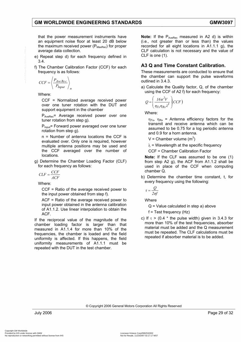
GM WORLDWIDE ENGINEERING STANDARDS GMW3097
that the power measurement instruments have an equipment noise floor at least 20 dB below the maximum received power (PMaxRec) for proper average data collection.
e) Repeat step d) for each frequency defined in 3.4.
f) The Chamber Calibration Factor (CCF) for each frequency is as follows:
nInput
cReAvePPCCF =
Where: CCF = Normalized average received power over one tuner rotation with the DUT and support equipment in the chamber PAveRec= Average received power over one tuner rotation from step g). PInput= Forward power averaged over one tuner rotation from step g). n = Number of antenna locations the CCF is evaluated over. Only one is required, however multiple antenna positions may be used and the CCF averaged over the number of locations.
g) Determine the Chamber Loading Factor (CLF) for each frequency as follows:
ACFCCFCLF =
Where: CCF = Ratio of the average received power to the input power obtained from step f). ACF = Ratio of the average received power to input power obtained in the antenna calibration of A1.1.2. Use linear interpolation to obtain the ACF.
If the reciprocal value of the magnitude of the chamber loading factor is larger than that measured in A1.1.4 for more than 10% of the frequencies, the chamber is loaded and the field uniformity is affected. If this happens, the field uniformity measurements of A1.1.1 must be repeated with the DUT in the test chamber.
Note: If the PAveRec measured in A2 d) is within (i.e., not greater than or less than) the values recorded for all eight locations in A1.1.1 g), the CLF calculation is not necessary and the value of CLF is one (1).
A3 Q and Time Constant Calibration. These measurements are conducted to ensure that the chamber can support the pulse waveforms outlined in 3.4.3. a) Calculate the Quality factor, Q, of the chamber
using the CCF of A2 f) for each frequency:
( )CCFληηVπ16Q 3
RxTx
2
⎟⎟⎠
⎞⎜⎜⎝
⎛=
Where: ηTx, ηRx = Antenna efficiency factors for the transmit and receive antenna which can be assumed to be 0.75 for a log periodic antenna and 0.9 for a horn antenna. V = Chamber volume (m3) λ = Wavelength at the specific frequency CCF = Chamber Calibration Factor
Note: If the CLF was assumed to be one (1) from step A2 g), the ACF from A1.1.2 shall be used in place of the CCF when computing chamber Q.
b) Determine the chamber time constant, t, for every frequency using the following:
fπ2Qτ =
Where Q = Value calculated in step a) above f = Test frequency (Hz)
c) If τ > (0.4 * the pulse width) given in 3.4.3 for more than 10% of the test frequencies, absorber material must be added and the Q measurement must be repeated. The CLF calculations must be repeated if absorber material is to be added.
© Copyright 2006 General Motors Corporation All Rights Reserved
July 2006 Page 29 of 32
Copyright GM Worldwide Provided by IHS under license with GMW Licensee=Visteon Corp/5962532002
Not for Resale, 11/23/2007 02:17:17 MSTNo reproduction or networking permitted without license from IHS
--``,,,,,,````,``,,`,,,,``,`,,,`-`-`,,`,,`,`,,`---

GMW3097 GM WORLDWIDE ENGINEERING STANDARDS
Table A1: Independent Samples and Frequencies
Frequency Range (MHz)
Number Of Samples (i.e. independent tuner positions or intervals) Recommended for
Calibration and Test)
Number Of Frequencies (logarithmically spaced) Required for Calibration
400 to 1000 12 20 1000 to 4000 6 15
> 4000 6 20/decade
Figure A1: Reverberation Test Configuration (Mode Tuning)
Note: Calibration shall consist of eight probe locations below 10 fs (4000 MHz) and three locations above 10 fs (4000 MHz). Note: The locations selected shall enclose the "working volume" as shown above. The working volume should be located at least 1 meter from the chamber walls, mode tuning device, and transmitting antenna. Note: The receive antenna must be located in the working volume for calibration purposes as described in A1.1.1 c). The transmit antenna shall be pointed into a corner at least 0.25 m away from the chamber surface. The transmit antenna shall remain in a fixed location for all calibrations and testing.
Note: The working volume may be sized to suit the size of the DUTs to be tested. Note: The minimum separation distance may be reduced less than 1 m provided that the separation distance is always at least 0.25 m.
© Copyright 2006 General Motors Corporation All Rights Reserved
Page 30 of 32 July 2006
Copyright GM Worldwide Provided by IHS under license with GMW Licensee=Visteon Corp/5962532002
Not for Resale, 11/23/2007 02:17:17 MSTNo reproduction or networking permitted without license from IHS
--``,,,,,,````,``,,`,,,,``,`,,,`-`-`,,`,,`,`,,`---
GM WORLDWIDE ENGINEERING STANDARDS GMW3097
© Copyright 2006 General Motors Corporation All Rights Reserved
July 2006 Page 31 of 32
Appendix B
B1 Typical Measurement Problems • Power for the DUT should be supplied from a
source free of electromagnetic emissions (e.g. batteries, linearly-regulated power supply). The use of switching power supplies is not recommended. If a power supply is used to simulate the battery, the low output impedance of the battery must be simulated. Using an actual battery or power supply capable of supplying at least twice the rated inrush current of the DUT is recommended.
• Experience has shown that double-shielded coaxial cable may be necessary to connect measurement equipment. Additionally, RF common mode chokes, such as ferrite cores, may be required on the cabling to reduce measurement errors.
• Placing the measurement instrumentation in a shielded or anechoic room may add to the background noise level. Extreme caution must be taken as to placement of equipment and
personnel if repeatable results are to be obtained.
• Since resonant frequencies may change from the bench setup to the vehicle, frequencies of noncompliance found during component testing may not necessarily be the same as the frequencies of noncompliance found during full-vehicle testing.
• Through experience it has been noticed that continuously generating the maximum rated output of an amplifier into a severe mismatch tends to limit its operating life. Therefore it may be beneficial to purchase a higher power amplifier than needed for each test.
• The interconnecting harness between a simulator and the DUT should be long enough to ensure that the simulator is not adversely affected by the magnetic field during magnetic field testing.
Copyright GM Worldwide Provided by IHS under license with GMW Licensee=Visteon Corp/5962532002
Not for Resale, 11/23/2007 02:17:17 MSTNo reproduction or networking permitted without license from IHS
--``,,,,,,````,``,,`,,,,``,`,,,`-`-`,,`,,`,`,,`---

GMW3097 GM WORLDWIDE ENGINEERING STANDARDS
Appendix C
C1 Emissions Test Report Sample
© Copyright 2006 General Motors Corporation All Rights Reserved
Page 32 of 32 July 2006
Band Region RF Service NameStartFreq.(MHz)
StopFreq.(MHz)
Maximum Emission
Non-SparkLimit Detector
dBuV dBuVEU1 Europe Long Wave (Note 1) 0.15 0.28 29 73 PKG1 Global Medium Wave / AM 0.53 1.71 35 42 PK
dBuV/m dBuV/mEU1 Europe Long Wave (Note 1) 0.15 0.28 29 41 PKM1 Global Medium Wave / AM 0.53 1.71 35 30 PK
NA1 America DOT I 45.2 47.8 8 12 PKG2 Global 4 Meter 62.5 88.1 22 12 PKJA1 Japan FM I 75.2 90.9 10 12 PKG3 Global FM II (except Japan) 86.6 109.1 11 12 PKG4 Global 2 Meter 140.6 175.8 17 12 PK
EU2 Europe Digital Audio Broadcast (DAB) 174.1 240 35 12 PKG5 Global RFA/TPMS I 314 316 8 20 PKG6 Global RFA/TPMS II 433 435 12 25 PKG8 Global Global Positioning System (GPS) 1567 1583 7 50-10-50 AVG
Artificial Network (AN) Conducted Emission (CE)
Aborber Lined Chamber (ALSE) Radiated Emissions (RE)
Emissions Exceed Limit for BandEmisions Meet Limit for Band
Note 1: Optional, applies to products intended for Fiat vehicles
Part Description: Unknown DeviceMode: Undefined ModeNotes: None
Part Category: A
Supplier Name: Anyone Parts Inc.Engineer Name: Joe SomebodySupplier Phone: (111) 555-5555
Test Number: MC-????Date Tested: AnytimeFile Name: Anyname
Lab Name: Anylab LLCOperator Name: SomeoneOperator Phone: (111) 666-6666
Non-Spark DeviceGMW3097 AN & ALSE Test Results
-10
0
10
20
30
40
50
60
70
0.1 1.0 10.0 100.0 1,000.0
MHz
dBuV
/m
Copyright GM Worldwide Provided by IHS under license with GMW Licensee=Visteon Corp/5962532002
Not for Resale, 11/23/2007 02:17:17 MSTNo reproduction or networking permitted without license from IHS
--``,,,,,,````,``,,`,,,,``,`,,,`-`-`,,`,,`,`,,`---

专注于微波、射频、天线设计人才的培养 易迪拓培训 网址:http://www.edatop.com
射 频 和 天 线 设 计 培 训 课 程 推 荐
易迪拓培训(www.edatop.com)由数名来自于研发第一线的资深工程师发起成立,致力并专注于微
波、射频、天线设计研发人才的培养;我们于 2006 年整合合并微波 EDA 网(www.mweda.com),现
已发展成为国内最大的微波射频和天线设计人才培养基地,成功推出多套微波射频以及天线设计经典
培训课程和 ADS、HFSS 等专业软件使用培训课程,广受客户好评;并先后与人民邮电出版社、电子
工业出版社合作出版了多本专业图书,帮助数万名工程师提升了专业技术能力。客户遍布中兴通讯、
研通高频、埃威航电、国人通信等多家国内知名公司,以及台湾工业技术研究院、永业科技、全一电
子等多家台湾地区企业。
易迪拓培训课程列表:http://www.edatop.com/peixun/rfe/129.html
射频工程师养成培训课程套装
该套装精选了射频专业基础培训课程、射频仿真设计培训课程和射频电
路测量培训课程三个类别共 30 门视频培训课程和 3 本图书教材;旨在
引领学员全面学习一个射频工程师需要熟悉、理解和掌握的专业知识和
研发设计能力。通过套装的学习,能够让学员完全达到和胜任一个合格
的射频工程师的要求…
课程网址:http://www.edatop.com/peixun/rfe/110.html
ADS 学习培训课程套装
该套装是迄今国内最全面、最权威的 ADS 培训教程,共包含 10 门 ADS
学习培训课程。课程是由具有多年 ADS 使用经验的微波射频与通信系
统设计领域资深专家讲解,并多结合设计实例,由浅入深、详细而又
全面地讲解了 ADS 在微波射频电路设计、通信系统设计和电磁仿真设
计方面的内容。能让您在最短的时间内学会使用 ADS,迅速提升个人技
术能力,把 ADS 真正应用到实际研发工作中去,成为 ADS 设计专家...
课程网址: http://www.edatop.com/peixun/ads/13.html
HFSS 学习培训课程套装
该套课程套装包含了本站全部 HFSS 培训课程,是迄今国内最全面、最
专业的HFSS培训教程套装,可以帮助您从零开始,全面深入学习HFSS
的各项功能和在多个方面的工程应用。购买套装,更可超值赠送 3 个月
免费学习答疑,随时解答您学习过程中遇到的棘手问题,让您的 HFSS
学习更加轻松顺畅…
课程网址:http://www.edatop.com/peixun/hfss/11.html
`

专注于微波、射频、天线设计人才的培养 易迪拓培训 网址:http://www.edatop.com
CST 学习培训课程套装
该培训套装由易迪拓培训联合微波 EDA 网共同推出,是最全面、系统、
专业的 CST 微波工作室培训课程套装,所有课程都由经验丰富的专家授
课,视频教学,可以帮助您从零开始,全面系统地学习 CST 微波工作的
各项功能及其在微波射频、天线设计等领域的设计应用。且购买该套装,
还可超值赠送 3 个月免费学习答疑…
课程网址:http://www.edatop.com/peixun/cst/24.html
HFSS 天线设计培训课程套装
套装包含 6 门视频课程和 1 本图书,课程从基础讲起,内容由浅入深,
理论介绍和实际操作讲解相结合,全面系统的讲解了 HFSS 天线设计的
全过程。是国内最全面、最专业的 HFSS 天线设计课程,可以帮助您快
速学习掌握如何使用 HFSS 设计天线,让天线设计不再难…
课程网址:http://www.edatop.com/peixun/hfss/122.html
13.56MHz NFC/RFID 线圈天线设计培训课程套装
套装包含 4 门视频培训课程,培训将 13.56MHz 线圈天线设计原理和仿
真设计实践相结合,全面系统地讲解了 13.56MHz线圈天线的工作原理、
设计方法、设计考量以及使用 HFSS 和 CST 仿真分析线圈天线的具体
操作,同时还介绍了 13.56MHz 线圈天线匹配电路的设计和调试。通过
该套课程的学习,可以帮助您快速学习掌握 13.56MHz 线圈天线及其匹
配电路的原理、设计和调试…
详情浏览:http://www.edatop.com/peixun/antenna/116.html
我们的课程优势:
※ 成立于 2004 年,10 多年丰富的行业经验,
※ 一直致力并专注于微波射频和天线设计工程师的培养,更了解该行业对人才的要求
※ 经验丰富的一线资深工程师讲授,结合实际工程案例,直观、实用、易学
联系我们:
※ 易迪拓培训官网:http://www.edatop.com
※ 微波 EDA 网:http://www.mweda.com
※ 官方淘宝店:http://shop36920890.taobao.com
专注于微波、射频、天线设计人才的培养
官方网址:http://www.edatop.com 易迪拓培训 淘宝网店:http://shop36920890.taobao.com