World War II - BACM Research€¦ · World War II: Messerschmitt 110 Flying Manual –...
14
World War II: Messerschmitt 110 Flying Manual “Instructions for flying the Messerschmitt 110” (1940) BACM RESEARCH WWW.PAPERLESSARCHIVES.COM
Transcript of World War II - BACM Research€¦ · World War II: Messerschmitt 110 Flying Manual –...

World War II:
Messerschmitt 110 Flying Manual
“Instructions for flying the Messerschmitt 110”
(1940)
BACM RESEARCH
WWW.PAPERLESSARCHIVES.COM


About BACM Research – PaperlessArchives.com BACM Research/PaperlessArchives.com publishes documentary historical research collections.
Materials cover Presidencies, Historical Figures, Historical Events, Celebrities, Organized Crime, Politics, Military Operations, Famous Crimes, Intelligence Gathering, Espionage, Civil Rights, World War I, World War II, Korean War, Vietnam War, and more. Source material from Federal Bureau of Investigation (FBI), Central Intelligence Agency (CIA), National Security Agency (NSA), Defense Intelligence Agency (DIA), Secret Service, National Security Council, Department of Defense, Joint Chiefs of Staff, Department of Justice, National Archive Records and Administration, and Presidential Libraries.
http://www.paperlessarchives.com

World War II: Messerschmitt 110 Flying Manual – “Instructions for flying the Messerschmitt 110” – A 1940 concise manual produced by the British Royal Air Force on flying the German Messerschmitt 110.

. For OffIcial Use Only
INSTRUCTIONS , . FORFLYIN@ ·. f ~
THE . -
MESSERSCHMITT }71 10
A.M. Pamphlet 114C
• ' Crown Copyr Ight R ese rved '

, , , ,
, "
A~ or flU lUAA GUll.
~~--~~+--!.
'"
\
i , \' , 1

GENERAL
INSTRUCTIONS FOR FLYING THE MESSERSCHMITT 110
The Messersc.hmitt 110 is a twin-engine row-wingmonoplane IOl\g-ran~e fighter or bomber. It Ilsuallyhas a crew of two but it can carry three. The span is about 53 feet, and the overall length 40 feet. ThetotaJ weight with R0nnalload is about 15,000 Ibs. when the wing loading is about 4Q Ibs. per sq. foot. It is of metal construction except for fabric covering on the control surfaces.
It is powered by two DB SOl engines each driving a V.n.M. variable-pitch and fully-feathering airscrew. the pitch of which is changed by an electric motor under the control of the pilot. The port engine drives a vacuurrr- pump and the starboard engine a hydraulic pump. There are two 24 volt t ikw.ciectricgeneratof5. onc driven by each engine. The flow of air through the coolant and oil radiators is controlled by flaps, moved by an electric motor for the coolant radiator and manually for the oil radiator.
The aircraft has automatic leading-edge slots, externally mass-balanced Frisetype ailerons, and flaps. Each aileron has a ground-adjustable trimmer-tab. The tailpIane incidence is variable, but only as a result of being connected to the flap mechanism; it cannot be independently adjusted by the pilot. The elevators and rudders have trimming tabs controlled by the pilot.
The main undercarriage is retractable but the tail wheel is fixed. The undercarriage. fl aps and wheel brakes are nonnally operated hydraulically,
hut an emergency system opera~ed by compressed air is provided for the under-carriage and flaps. •
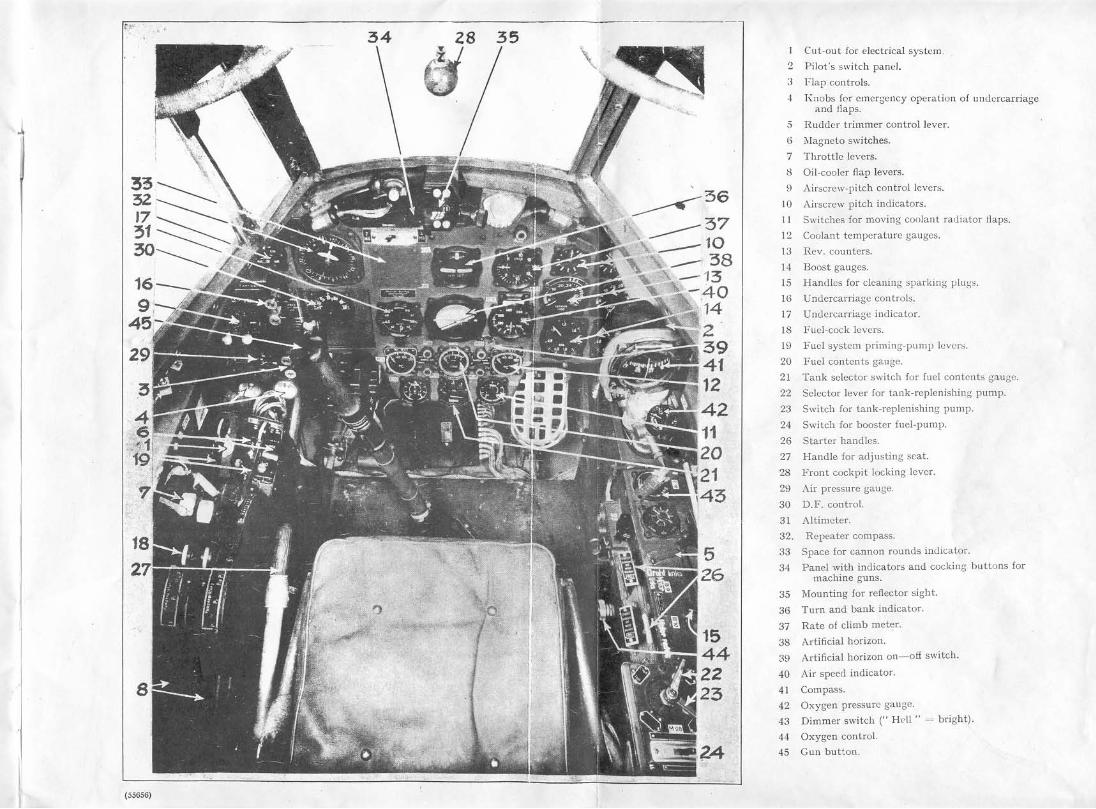
The pilot:s cockpit is shown in the accompanying illustration . The numbers in brackets in the following description are the numbers used in the key adjacent to the illustration. There is a conversion table inside the back cover.
ELECTRICAL SYSTEM The main switch is a black knob, on the pilot's ri~ht, out of view in the
illustration. It is movable fore-and-aft. When the knob is moved forward and turned <lown into the notch, the main circuit is switched on and the starter system connected to the aircraft battery. If the knob is th"n let back ~ently the main circuit remains switched on, but the slarter system is connected to the ground battery socket, on the starboard side of the fuselage just aft of the trailing edge. If it is let back quickly and then the red disc (I), which is an electric cut-out, is pressed, the main circuit is disconnected from the aircraft battery. This cut-out (I) can be l\Sed by itself to disconnect the main circuit in an emergency.
The individual circuits of the various 'electric services are controlled by switches on two panels, one on the starboard side of the rear seat, and one (2) on the right and forward of the pilot's seat, near the dashboard. The former panel has 17 switches. All these except the aft four must be pressed in to close the various circuits necessary for flying the aircraft. The aft four close the circuits of various units of the wireless equipment. There is a combined voltmeter and ammeter on the upper part of this panel. It normally shows the battery charging or discharl::"ing current, the left half of the scale in-j ic3.tin~ charging and the right half dischargin<7; but when the button on it is pressed it indicates battery volts. '"
The second panel (2) has seven switch buttons which close. when pushed in. the following circuits, reading from forward :-
landing light, recognition lights, instrument lighting, pitot head heating, machine-guns and sight, shell guns, cockpit lighting.
The switches on t~ese two panels open automatically if there is an over-load, tllus acting like fuses. They can be opened manually by pressing the adjacent red buttons. In some cases it is necessary to push through a small hole to do this.
''''''' .<
2
TIlE FLYING CONTROlB
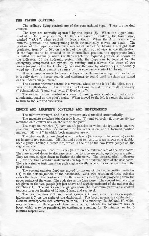
The ordinary flying controls are of the conventional type. There are no dual controls.
The flaps are normally operated by the knobs (3). When the upper knob, marked" E.IK ", is pushed in, the flaps are nused. Similarly. the lower knob, marked" AUS ", when pushed in, lowers them. When the flaps reach either extreme FGsiticn, the corresponding knob autcmatically moves c.ut again. The position of the flaps is shown on a mechanical indicator, having a straight scale graduated from 0° to 50°, on the left of the pilot, out of view in the illustration. If the flaps are to be arrested in an intermediate position, the appropriate knob is pulled out manually when the flaps reach the required position as shown on the indicator. If the hydraulic system fails, the flaps can be lowered by the emergency compressed air system, by turning anti-clockwise the inner of two knobs (4) just below the knobs (3), . breaking the wire by which they are normally wired-up. The flaps cannot be raised by the emergency control blObs (4). .
If an attempt is made to lower the flaps whue the undercarnage IS up or before it is fully down, a hooter sounds and continues to sound until the flaps arc raised or the Wldercarriage lowered.
The elevator trinuner control is a vertical wheelan the left of the pilot, out of view in the illustration. It is turned anti-clockwise to make the aircraft tail-heavy (" Schwanzlastig ") and vice-versa (" Kopflastig ").
The rudder trimmer control is a lever (5) moving over a notched quadrant on a horizontal panel on the pilot's right. When moved to the left it causes the aircraft to turn to the left and vice-versa.
EIIGIIiE AIID AIRSCREW CONTROl.'! AIID INSTRUMENTS
The mixture-strength and boost pressure are controlled automatically. The magneto switches (6); throttle levers (7), and oil-cooler flap levers (8) are
mOWlted on a control box on the left of the pilot. The magneto switches (6) have an aft position in which the ignition is off, two
positions in which either one magneto or the other is on, and a forward position marked" MI + 2 " in which both magnetos are on.
The oil-cooler flaps are closed when the levers (8) are up. The levers (8) can be set in any of five positions. Oil inlet and outlet temperatures arc shown on a doubleneedle gauge, having a brown rim, which is the aft of the two lower gauges on the engine nacelle.
The airscrew-pitch control levers (9) are on the extreme left of the dashboard. They are moved down to decrease revs., i.e .. to increase pitch, up to decrease pitch. They are moved right down to feather the airscrews. The airscrew-pitch indicators (10) are the two clock-like instruments on top at the extreme right of the dashboard. There is a similar instrument on..each engine nacelle, where it can be seen from the pilot's seat.
The coolant-radiator flapS are moved by means of the two 9-position switches (11) at tl;le bottom middle of the dashboard. Clockwise rotation of these switches closes the flaps. The .positions of the flaps are indicated by rods projecting from the upper surface of the wing. The rods rise as the flaps close. The coolant temperatures are given on the two gauges (12) just above and slightly outboard of the radiator-flap switches (11). The marks on the gauges show the maximum permissible coolant temperatures for heights of 10 km., 5 km., and sea level.
The rev. counters (13) and' boost gauges (14) are below the airscrew-pitch indicators (1O) on the right of the dashboard. The boost gauges are calibrated in German atmospheres (see conversion table). The markings D, 30' and 5', which may be found on the edges of these instruments, indicate the maximum revs. or boost which may' be permitted for continuous running, for 30 minutes, or for 5 minutes respectively.

3
The ignition can be retarded in order to burn oil off the plugs by pulling up the handles (IS) on the horizontal panel on the pilot's right. The forward handle is for the port engine.
TIlE UNDERCARRJAGE AND BRAKES
The normal undercarriage controls (16) are above the not mal flap controls (3) and are operated in the same way, the upper knob,when pressed in, raising the under~ carriage and the lower knob lowering it. A small projection on the upper knob must be pushed do'Ml before the knob can be pushed in. The indicator (17) is just above the controls. If the switch at the bottom of this instrument is moved to the right , the instrument shows two green lights, one for each side. if the undercarriage is down C' AUS >0) and red lights if it is up C' EIN ").
If the hydraulic system fails, the undercarriage may be lowered by turning anticlockwise the outer of the emergency knobs (4).
The brake~ are applied by toe pressure on the rudder pedals. There is no parking brake.
THE FUEL SYSTEM
There is a main and a reserve tank in each wing, both inboard of the engine, tile fonner forward of the single spar and the Jatter behind it. The engine takes fuel only from the main or forward tank by a dual engine-driven pump through two lines. These lines are opened or closed by fuel cocks operated by levers (18) on the control box to the left of the pilot. When the levers (18) arc in their rear positions, marked " Brandhahn Zu," fuel is cut off from the engines. In the forward position" PI u. P2" both lines arc open, and in the two intennediate positions only one or the other of the lines.
The fuel lines are primed and the fuel initially brought to the required pre~ure by pumps operated by reciprocating the hand levers (19) also on the control bo~;, forward of the throttle levers. The fuel pressure gauges, calibrated ill kg. per sq. cm. are combined with the oil pressure gauges, and are on the engine nacelles. The lcfthand needle indicates fuel pressure and the right-hand oil pressure. Permissible limits are indicated by the L-shaped marks.
Each main tank holds 375 litres (82·5 gallons) and each reserve tank 260 litres (58 gallons). Tank contents are shown on the gauge (20) in the middle and ncar the bottom of the dashboard. It has two scales, each calibrated in hundreds of litres. The upper scale refers to the main or fonvard tanks, the lower to the reserve tanks. The gauge is put over to the various tanks by a 5'vosition selector switch (21) immediately beneath it. The 5 positions, reading clockwise are :-
(0) off (1) port main tank (2) starboard main tank (3) port reserve tank (4) starboard reserve tank.
When the main tank contents fall to 100 litres (22 gallons), which is indicated by the lighting of the upper warning lights on each side of the gauge, fuel must be transferred from the reserve tank. This is done by pumps controlled by selector and switch levers (22 and 23) on the horizontal panel on the pilot's right. The forward lever (22) is first set to left or right depending on whether the port or starboard main tank is to be replenished. Then the pump is switched on by moving the lever (23)
. to the left (" EIN "). The lower lights light when the petrol in the reserve tanks gets low.
The engine cylinders can be primed by means of a pump and a two-way cock, out of view, aft of the levers (22 and 23). The cock is put forward to" reebter ", to prime the starboard engine, and aft to " linker" for the port engine.
•
4
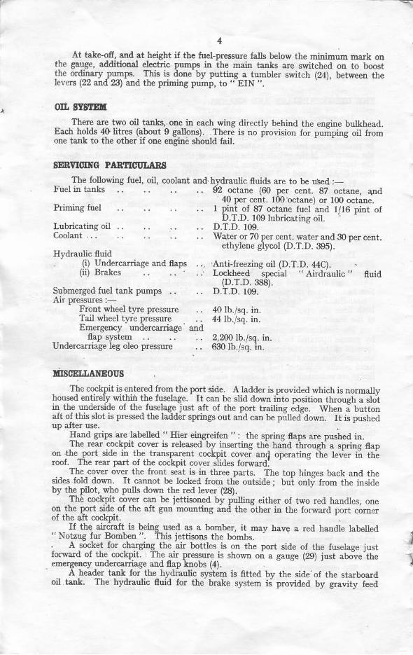
At take-off, and at height if the fuel-pressure falls below the minimum mark on the gauge, additional electric pumps in the main tanks are switched on to boost the ordinary pumps. This is done by putting a tumbler switch (24), between the levers (22 and 23) and the priming pump, to" EIN " ,
OIL SiS'l'EILI
There are two oil tanks, one in each wing directly behind the engine bulkhead. Each holds 4f) litres (about 9 gallons). There is no provision for pumping oil from one tank to the other if one engine should fail.
SERVICING PARTICULARS
The following fuel, oil, coolant and· hydraulic fluids are to be u~d :-Fuel in tanks 92 octane (60 per cent. 87 octane, and
Priming fuel
Lubricating oil Coolant . ..
Hydraulic ftuid (i) Undercarriage and flaps
(ii) Brakes
Submerged fuel tank pumps Air pressures :-
Front wheel tyre pressure Tail wheel tyre pressure Emergency undercamage and
flap system Undercarriage leg oleo pressure
lIiIsoELLANEOUS
40 per cent. too 'octane) or 100 octane. I pint of 87 octane fuel and 1/16 pint of
D.T.D. 109 lubricating oil. . D.T.D. 109. Wa.ter or 70 per cent . water and 30 per cent.
ethylene glycol (O.T.D. 395).
'Anti-freezing oil (D.T.D. 44C). Lockheed special " Airdraulic "
(D.T .D. 388). D.T.D. 109.
40 Ib./sq. in . 44 lb./sq. in.
2,200 lb./sq . in. 630 Ib./sq. in.
fluid
The cockpit is entered from the port side. A ladder is provided which is normally housed entirely within the fuselage. It can be slid down into position through a slot in the underside of the fuselage just aft of the port trailing edge. When a button aft of this slot is pressed the ladder springs out and can be pulled down. I t is pushed up after use.
Hand grips are labelled .. Hier eingreifen ": the spring flaps are pushed in. The rear cockpit cover is released by inserting the hand through a spring flap
on ·the port side in the transparent cockpit cover an9 operating the lever in the roof. The rear part of the cockpit cover slides forward.
The cover over the front seat is in three parts. The top hinges back and the sides fold down. It cannot be locked from the outside; but only from the inside by the pilot. who pulls down the red lever (28).
The cockpit cover can be jettisoned by pulling either of two red handles, one on the port side of the aft gun mounting and the other in the forward port comer of the aft cockpit.
If the aircraft is being used as a bomber, it may have a red handle labelled 1 "Notzug fur Bomben ". This jettisons the bombs.
A socket for charging the air bottles is on the port side of the fuselage just forward of the cockpit. The air pressure is shown on a gauge (29) just above the emergency undercarriage and flap knobs (4).
A beader tank for the hydraulic system is fitted by the side' of the starboard oil tank. The hydraulic fluid for the brake system is provided by gravity feed

f
5
from a small tank at the top and starboard side of the fuselage nose. Access to the tank is gained by sliding forward the top nose gun cowling and removing four screws in the top of the bulkhead.
STARTING THE ENGINES The engines are turned for starting by inertia starters which can be energised
by hand, electrically from the aircraft battery, or electrically from a ground battery. The manner in which the starter system is connected to one battery or the other is explained above under" Electrical System".
The starters are engaged, after they have been run-up, by pulling up T-shaped handles (26) on the right of the pilot. These handles are normally covered by safety flaps which are swung aside when the handles are to be operated. The forward handle is for the port engine.
The hand-starting sockets are on the starboard side of each engine, just to rear of the aft exhaust stub. The handle is usually stowed inside the undercarriage cavity in the port engine nacelle.
To start electrically, the handle (26) is first pushed down and held down for 10 secs. if engine is hot, 20 secs. if cold. This runs up starter. Then it is pulled right up through neutral to engage the starter.
Th/,! sequence of operations in starting is as follows :-(i) Switch on the main electrical system by pulling forward the knob on the
right-hand side of the cockpit. Let back gently if starting on ground battery.
(ii) Press in all the switches on the panel in the rear cockpit except the aft four.
(iii) Open the cooling flaps of the oil and coolant radiators by moving levers (8) up and turning switches (11) anti-clockwise.
(iv) Set the airscrews in nne pitch corresponding to 12 o'clock on the indicators (10) by moving levers (9) up.
(v) Open the throttles (7) about half an inch. (vi) Place the fuel-cock levers (18) forward to position" PI u. P2 ".
(vii) Put the magneto switches (6) in position" MI + 2 ". (viii) Give each engine about 8 strokes of the primer pump.
(ix) Pump up the fuel pressure by handles (19) and keep pumping throughout the next two operations until the engine fires . It will be found impossible to exceed a pressure of about t kg. per sq. crn.
(x) Tum the starter by the crank handle, or electrically by depressing the handle (26), and then pull the handle (26) right up to engage starter.
The engine may be stopped by pulling out the small ring sticking out of the engine nacelle just aft of the rear exhaust stub on the inboard side. Release when engine stops.
GROUND RUNNING
Run the engine at 1,900 r.p.m. and.-(i) Test each magneto by placing the switches (6) to positions" Ml "
and" M2" in turn. The allowable r.p.m. drop on " )11 " is to, and on"M2"70.
(ii) Test the fuel pumps by placing the fuel cock levers (18) into positions "Pt and" P2" in tum. There should be no r.p.m. drop in either position.
(iii) When the oil outlet temperature has reached 40° C. open the throttles gradually until the full-throttle ground-running conditions of 2,200 r.p.m. approximately at 1·3 atmospheres boost pressure have been reached.
FLYING THE AIRCRAFT Take-off.-See that the airscrew pitch (9) is 12 o'clock on the ir0icators (10) .
. It is not necessary to use flaps for take-off. Set the elevator trimmer to the red mark on the indicator; set the rudder trimmer (5) in the centre position. The tail is
(5 5(;5fi ) ,

-.
I ,
t
6
fairly heavy, and takes some time to rise, even with the stick held well forward. :r:he take-off run is ioog and the directional control is poor, until 120 m.p.h. is reached. Quite a lot of rudder has to be used to keep the aircraft straight at low speeds.
Flight.-The controls arc fairly light and very effective up to 250 m.p.h. Above tbis they become heavy, but not unduly so for a twin-cngined aircraft. Owing to the 'weigJJt· ,oo the elevators at high speed, plenty of room should be allowed for recovery £rom d ives.
Landing.-Lower undercarriage fully before lowering flaps. When the flaps are lowered a large change of attitude takes place. At the commencement of the lowering the nose rears upwards, and a large forward force on the elevators is required to counteract it. Towards the end of tbe flap nlOvemcnt the nose starts to sink and a backward movement of the elevator control -is required. The eventual chan!:e of trinlTequired when the flaps are in use is very small. The ailerons desc~nd at , the same time as the flaps, and a sudden lightening of their control is noticed, but there is no marked loss of effectiveness.
The approach should be carried out at about 160 km.p.h. (95/100 m.p.h.) and is Jrtraightforward , the excellent wew ahead making it easy. The landing is normal unless done too high, when there is a tendency for a wing to drop.
Tile ground run is about the same as that of a Blenheim.
Single Engine Aptn'O&Cb.-Should one engine cut, fully feather the dead airscrew and use only 25<> flap for the approach glide. If full flap is used, more than 1,600 revs. on the good engine will cause unconlJo\labJe swing and b.1.nk, leading to the loss of anything up to 1,800 ft.
EllOIIIE OPERATIONAL LIlInTATIONS Full throttle, givihg 1·3 atmos. boost pressure, below 14,000 ft. approximately,
should not be used for over 5 mi~utes at a time. Time
C01u/iti01I Mi'ls. . R.P.M. Take-off 5 2400
Climbing and level cruising lip ~~} 5 2400
30 2300 .5 Km. (16,400 ft.) .. Continuous 2200 Level cruising above 5 Km. (16,400
ft .) .. Continuous 2400 Limit in dive .. 2500
Minimum r.p.m. at various boost pressures :-Boost pressure I . I 1 ·05 0·95
1500 Minimum r.p.m... 1800 1700 Oil pressure :
(i) Take-off
(ii) Minimum at 2400 r.p.m. Oil temperatures :-
Maximum 5 Kg. per sq. em. Minimum 2·5 Kg. per sq. em. 2·2 Kg. per sq. em.
[Joost (Af1llosphaes)
1·3 1·3 1·2 1'18
1·18
0·9 atmos. 1400
(i) Inlet Maximum 75° C. (u) Outlet Maximum 95<> C.
Minimum 30° C. Minimmn 40° C.
(iii) Maximum for short period only = 105<> C.
AIRCRAF1' LIMITATIONS Maximum permissible speed (A.S.T.) 650 Km./hr. (406 m.p.h,.) Maximum permissible speed (A.5.1.) with flaps and
undercarriage down 250 Km. jhr. (ISS m.p.h.) Best approach speed (A.S.I.) (as determined by
R.A.E. pilots) 160 Km./hr. (100 m.p.h.)
A.l.I(g) ($5&$4» W'.1225313S:'1 2.'1100. 8141 H .... G.371
.34 28
fi Cut-out for electrical sy~tcm
2 Pik,t's switch panel.
" Flap ~ontrols.
4 I~ nobs fer emergency op.:ration of undcrcarria"e
• and liaps .
5 l~uddcr trimmer control lever.
" ,"agnclo switches.
7 Throttle levers. , Oil-cooler flap levers.
" Airscrew-pitch control levers.
" Airscrew pilch i"dicator~.
II Switches for moving coolant radidtor Jlaps.
11 Coolant temperature gauges.
U Rev. counters.
14 1300st gauges.
15 Handk~ for cleaning spark"lg plug",
16 Undcrcarriasc controls.
17 Undercarriage indicator.
18 Fud-c<xk levers.
l' Fuel syslem priming·pump !t;vcr,;.
20 Fuel contents gauge.
21 Tank selector switch for fuel contents gauge.
22 Selector lever for tallk- replenishing pump.
23 Switch for tank-replenishing pump.
24 Switch for booster fuel -pump.
26 Starter handles ,
27 Handle for adju~ting scat.
28 Front cockpit locking lever ,
28 Air pressure gauge,
30 D.F . control.
31 Altimeter.
32. Repeater compass.
33 Space for cannon rounds indicator.
34 Panel willi indicator~ and cocking \JUllUllS lor machine guns.
35 Mounting lor reflector sight.
36 Turn and bank indicator.
37 Rate 01 climb meter.
38 Artificial horizon.
39 Artificial horizon on- oil switch.
40 Air sp<:ccl indicator.
41 Compass.
42 Oxygen pressure gauge.
43 Dimmer switch (" Hl'll " = bright).
" Oxygen control.
45 Gun button.

"
t • •
' . • or •
•
" •
• • •
•
" .',
•
,