World Association of Technology TeachersSECTIONAL VIEWS ORTHOGRAPHIC PHOTOGRAPHS IN REAL TIME AS YOU...
4
W.A.T.T. World Association of Technology Teachers On behalf of The World Association of Technology Teachers This exercise can be printed and used by teachers and students. It is recommended that you view the website (www.technologystudent.com) before attempting the design sheet . THESE MATERIALS CAN BE PRINTED AND USED BY TEACHERS AND STUDENTS. THEY MUST NOT BE EDITED IN ANY WAY OR PLACED ON ANY OTHER MEDIA INCLUDING WEB SITES AND INTRANETS. NOT FOR COMMERCIAL USE. THIS WORK IS PROTECTED BY COPYRIGHT LAW. IT IS ILLEGAL TO DISPLAY THIS WORK ON ANY WEBSITE/MEDIA STORAGE OTHER THAN www.technologystudent.com V.Ryan © 2000 - 2012 PRODUCT DEVELOPMENT EXERCISE DEVELOPMENT DESIGN SHEET 3
Transcript of World Association of Technology TeachersSECTIONAL VIEWS ORTHOGRAPHIC PHOTOGRAPHS IN REAL TIME AS YOU...
W.A.T.T.
World Association of Technology Teachers
On behalf of The World Association of Technology Teachers
This exercise can be printed and used by teachers and students. It is recommended that you view the website (www.technologystudent.com) before attempting the design sheet .
THESE MATERIALS CAN BE PRINTED AND USED BY TEACHERS AND STUDENTS.
THEY MUST NOT BE EDITED IN ANY WAY OR PLACED ON ANY OTHER MEDIA INCLUDING WEB SITES AND INTRANETS.
NOT FOR COMMERCIAL USE.THIS WORK IS PROTECTED BY COPYRIGHT LAW.
IT IS ILLEGAL TO DISPLAY THIS WORK ON ANY WEBSITE/MEDIA STORAGE OTHER THAN www.technologystudent.com
V.Ryan © 2000 - 2012
PRODUCT DEVELOPMENT EXERCISEDEVELOPMENT DESIGN SHEET 3

V.Ryan © 2012 World Association of Technology Teachers
PRODUCT DEVELOPMENT EXERCISEPAGE THREE
THE TAPE MEASURE
Study the sample development page (page 2).
How many of the key areas (page 3)have been mentioned on this sheet? Place a tick
against the areas included.(See slide three for key areas)
What grade would you give this development sheet?
WHAT AREAS / TECHNIQUES NEED TO BE INCLUDED ON THE FOLLOWING
DEVELOPMENT SHEETS?

V.Ryan © 2012 World Association of Technology Teachers
PRODUCT DEVELOPMENT SHEET 3NAME:
An ultra bright LED shines directly on to the scale portion of measuring tape. The lens, enlarges the scale reading, so that it is easy to read.The rotating tape mechanism, can be seen inside the casing. It is illuminated when the LED turns on.The extent of the rubber comfort grip can be seen, the average width of the palm of the hand.The CAD drawing, allows the design to be viewed as a realistic model.
LED
MAGNIFYING LENS
TRANSPARENTVIEWER
RUBBER COMFORT GRIP
This CAD drawing clearly shows how the lens magnifies the scale. The red ‘datum’ line, identifies the measurement precisely.
The rubber grip, at the base of the tape measure, has ‘teeth’, that grip the material it is placed on.
ILLUMINATED POLYCARBONATE
WINDOW
This CAD exploded drawing, shows how the basic design looks when disassembled. I showed this to the focus group, to explain my initial thoughts about joining the various parts. They suggested developing a friction fit casing, rather than relying on small screws.
RUBBERCOMFORT
GRIP
MAIN CASING
RUBBER GRIP
STORAGEHOOK
PLASTICRIVETS
TAPE MEASURE
INTERNALMECHANISM POLYCARBONATE
WINDOW
SIDE
The casing could be manufactured in a range of colours. Four fashionable samples are seen opposite. My design will not be traditional, but will reflected the fact that many tape measures are bought and used by people to carry out DIY at home. The design uses popular colours, not only more traditional colours, used in industry.
SAMPLE FASHIONABLE COLOURS
TYPICAL TRADITIONALTAPE MEASURE
I LIKE IT!
IT COULD BE BETTER
COLOURFUL
COMFORTABLEWILL IT WORK?
WHAT COST?
My Focus Group, discussed the first design and viewed the CAD model. They quite liked it, especially the ergonomics and the comfortable handling. They suggested that I should develop the circuit, battery replacement, make real models and consider how the parts will be manufactured.The CAD drawings below, show the different types of storage ‘hooks’ I am
considering. My favourite is the magnet, because of its simplicity and because it will secure the tape to a steel shelf, piece of steel equipment or steel tool box.
PLACE PHOTOGRAPH HERE
The LED light could be one of several colours. This means that the light emitted from the clear
window could be colourful, as well
a functional.
A vinyl cutter could be used to manufacture the lettering / logo for the tape measure.
Alternatively, I will consider some form of engraving, possibly by a laser cutter.
Vacuum forming the casings for the tape measure, seems a good manufacturing option at this stage. It will certainly work well for the prototypes and models.Both the main casing and the side, could be designed to fit tightly together, forming a friction fit. This would avoid the need for small screws.
MATERIALS: Polycarbonate has good impact resistance properties, especially when combined with rubber. Alternatively, I will consider kevlar for the casing with an elastonomer for the ‘rubber’ grip. The elastonomer, will combine the strength of plastic, with the flexibility of rubber.
V.Ryan © 2012 World Association of Technology Teachers
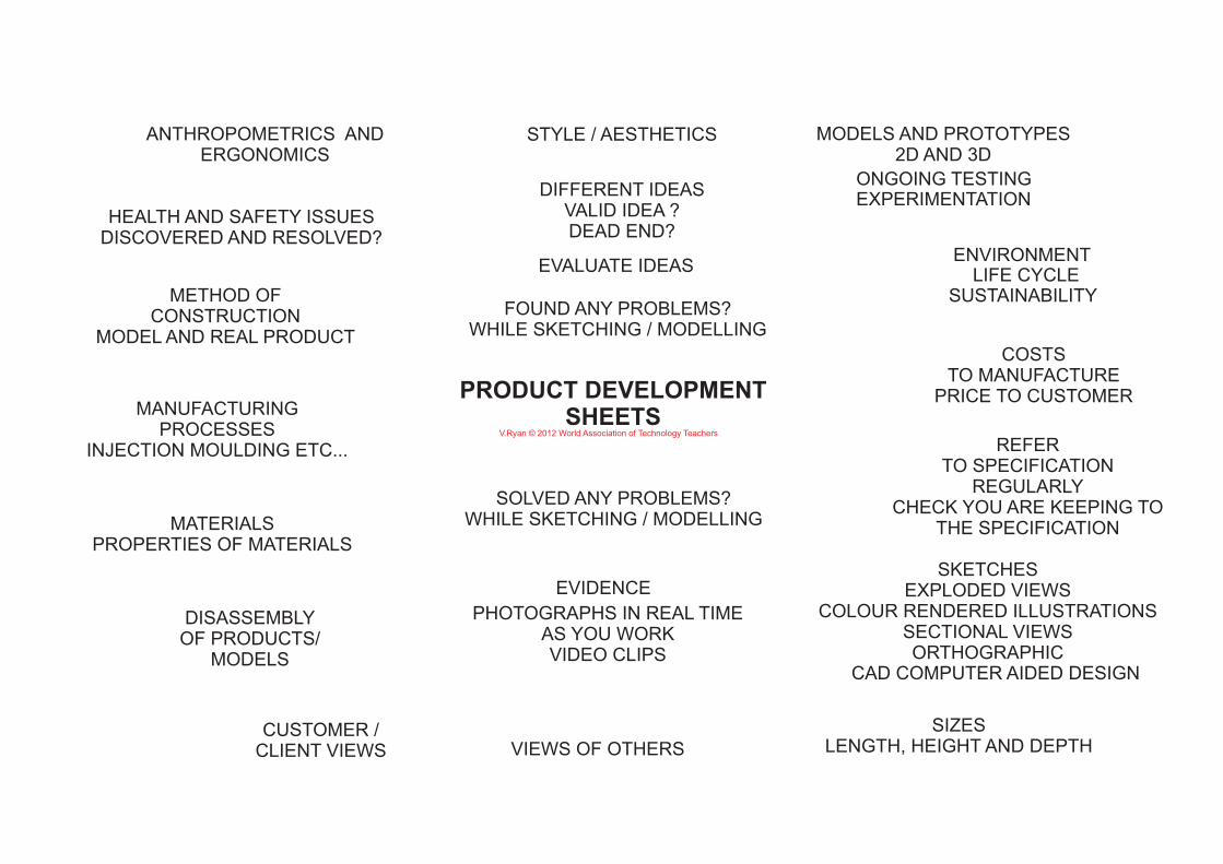
ANTHROPOMETRICS ANDERGONOMICS
STYLE / AESTHETICS MODELS AND PROTOTYPES2D AND 3D
CUSTOMER / CLIENT VIEWS VIEWS OF OTHERS
SIZESLENGTH, HEIGHT AND DEPTH
COSTSTO MANUFACTURE
PRICE TO CUSTOMER
REFER TO SPECIFICATION
REGULARLYCHECK YOU ARE KEEPING TO
THE SPECIFICATION
FOUND ANY PROBLEMS?WHILE SKETCHING / MODELLING
SOLVED ANY PROBLEMS?WHILE SKETCHING / MODELLINGMATERIALS
PROPERTIES OF MATERIALS
PRODUCT DEVELOPMENT SHEETS
CAD COMPUTER AIDED DESIGN
SKETCHESEXPLODED VIEWS
COLOUR RENDERED ILLUSTRATIONSSECTIONAL VIEWSORTHOGRAPHIC
PHOTOGRAPHS IN REAL TIMEAS YOU WORKVIDEO CLIPS
DISASSEMBLYOF PRODUCTS/
MODELS
METHOD OF CONSTRUCTION
MODEL AND REAL PRODUCT
MANUFACTURING PROCESSES
INJECTION MOULDING ETC...
DIFFERENT IDEASVALID IDEA ?DEAD END?
ENVIRONMENTLIFE CYCLE
SUSTAINABILITY
ONGOING TESTING
EVIDENCE
HEALTH AND SAFETY ISSUESDISCOVERED AND RESOLVED?
EXPERIMENTATION
EVALUATE IDEAS