
workshopmanual - guzzitek.orgGB).pdf · dealers and agencies world-wide. ... VALLEY FORGE DECA...
108
workshopmanual 00/2005-10 Engine V1100 UK Cod. 8140898 UK Cod.
Transcript of workshopmanual - guzzitek.orgGB).pdf · dealers and agencies world-wide. ... VALLEY FORGE DECA...

workshopmanual
00/2
005-
10
Engine V1100
UK
Cod.
8140
898
UK
Cod.
INTRODUCTION
0 - 1
Engine V1100
INTRODUCTION 0

INTRODUCTION
0 - 2
Engine V1100
SUMMARY 0.1. INTRODUCTION .............................................................................................................................................. 3
0.1.1. FOREWORD ............................................................................................................................................. 3 0.1.2. REFERENCE MANUALS .......................................................................................................................... 4 0.1.3. ABBREVIATIONS/SYMBOLS/CONVENTIONS ........................................................................................ 5
INTRODUCTION
0 - 3
Engine V1100
0.1. INTRODUCTION 0.1.1. FOREWORD
This manual provides the information required for normal servicing. This publication is intended for use by Moto Guzzi Dealers and their qualified mechanics; many concepts have been omitted on purpose as their inclusion would be superfluous. Since complete mechanical explanations have not been included in this manual, the reader must be familiar with basic notions of mechanics, as well as with basic repair procedures. Without such familiarity, repairs and checks could be ineffective and even hazardous. Since the repair and vehicle check instructions are not exhaustive, special care must be taken to avoid damage and injury. Moto Guzzi s.p.a. undertakes to constantly improve the design of its products and their literature to ensure that the customer is satisfied of the product. The main technical modifications and changes in repair procedures are communicated to all Moto Guzzi dealers and agencies world-wide. Such modifications will be entered in subsequent editions of the manual. Should you need assistance or clarifications about the inspection and repair procedures, please contact the Moto Guzzi SERVICE DEPT., they will be glad to give you any information on the matter, or supply you with any detail on updates and technical changes applied to the vehicle. Moto Guzzi s.p.a. reserves the right to make changes to its products at any time, barring any such changes as may alter the essential features of a product as specified in the relevant manual. All rights of storage using electronic means, reproduction and total or partial adaptation, whatever the means adopted, are reserved in all countries. Third parties' products are only mentioned for information purposes, and constitute no engagement. Moto Guzzi s.p.a. is not liable in any way for the performance or use of these products. For further details, see (REFERENCE MANUALS). First edition: October 2005 Produced and printed by: VALLEY FORGE DECA Ravenna, Modena, Torino DECA S.r.l. Registered Office and Administrative Headquarter via Vincenzo Giardini, 11 - 48022 Lugo (RA) - Italy Tel. +39 - 0545 216611 Fax +39 - 0545 216610 E-mail: [email protected] www.vftis.com On behalf of: Moto Guzzi s.p.a. via E.V. Parodi, 57- 23826 Mandello del Lario (Lecco) - Italy Tel. +39 0341 - 709111 Fax +39 0341 - 709220 www.motoguzzi.it www.servicemotoguzzi.com

INTRODUCTION
0 - 4
Engine V1100
0.1.2. REFERENCE MANUALS
PARTS CATALOGUES guzzi part# (description) GU077_00
OWNER'S MANUALS guzzi part# (description) 05.90.00.30 05.90.00.31
CHASSIS WORKSHOP MANUAL guzzi part# (description) 8140856 8140857 8140858 8140859 8140860 8140861 8CM0077 8CM0078
ENGINE WORKSHOP MANUAL guzzi part# (description) 8140894 8140895 8140896 8140897 8140898 8140899
CD FOR THE NETWORK guzzi part# (description) 8CM0093 8CM0094

INTRODUCTION
0 - 5
Engine V1100
0.1.3. ABBREVIATIONS/SYMBOLS/CONVENTIONS
# = number < = less than > = greater than ≤ = less than or equal to ≥ = more than or equal to ~ = approximately ∞ = infinity °C = degrees Celsius (centigrade) °F = degrees Fahrenheit ± = plus or minus a.c = alternating current A = Ampere Ah = Ampere per hour API = American Petroleum Institute AT = high voltage AV/DC = Anti-Vibration Double Countershaft bar = pressure measurement (1 bar = 100 kPa) d.c. = direct current cc = cubic centimetres CO = carbon monoxide CPU = Central Processing Unit DIN = German industrial standards (Deutsche Industrie Norm) DOHC = Double Overhead Camshaft ECU = Electronic Control Unit rpm = revolutions per minute HC = unburnt hydrocarbons ISC = Idle Speed Control ISO = International Standardisation Organisation kg = kilograms kgm = kilogram metre (1 kgm = 10 Nm) km = kilometres km/h = kilometres per hour kΩ = kilo Ohm kPa = kiloPascal (1 kPa = 0.01 bar) KS = clutch side (from the German "Kupplungsseite") kW = kilowatt l = litres LAP = racetrack lap LED = Light Emitting Diode LEFT SIDE = left side m/s = metres per second max = maximum mbar = millibar (1 mbar = 0.1 kPa) mi = miles MIN = minimum MPH = miles per hour MS = flywheel side (from the German "Magnetoseite") MΩ = MegaOhm N.A. = Not Available N.O.M.M. = Motor Octane Number N.O.R.M. = Research Octane Number Nm = Newton metre (1 Nm = 0.1 kgm) Ω = ohm PICK-UP = pick-up BDC = Bottom Dead Centre TDC = Top Dead Centre PPC = Pneumatic Power Clutch RIGHT SIDE = right side SAE = Society of Automotive Engineers SAS = Secondary Air System
INTRODUCTION
0 - 6
Engine V1100
TEST = diagnostic check T.B.E.I. = crown-head Allen screw T.C.E.I. = cheese-head Allen screw T.E. = hexagonal head T.P. = flat head screw TSI = Twin Spark Ignition UPSIDE- DOWN = inverted fork V = volt W = watt Ø = diameter

GENERAL INFORMATION
1 - 1
Engine V1100
GENERAL INFORMATION 1

GENERAL INFORMATION
1 - 2
Engine V1100
SUMMARY 1.1. STRUCTURE OF THE MANUAL...................................................................................................................... 3
1.1.1. CONVENTIONS USED IN THE MANUAL................................................................................................. 3 1.1.2. SAFETY WARNINGS ................................................................................................................................ 4
1.2. GENERAL RULES............................................................................................................................................ 5 1.2.1. BASIC SAFETY RULES ............................................................................................................................ 5
1.3. DANGEROUS ELEMENTS............................................................................................................................... 8 1.3.1. WARNINGS............................................................................................................................................... 8
1.4. RUNNING-IN .................................................................................................................................................. 11 1.4.1. RUNNING-IN ........................................................................................................................................... 11
1.5. POSITION OF THE SERIAL NUMBERS ........................................................................................................ 12 1.5.1. POSITION OF THE SERIAL NUMBERS................................................................................................. 12
GENERAL INFORMATION
1 - 3
Engine V1100
1.1. STRUCTURE OF THE MANUAL 1.1.1. CONVENTIONS USED IN THE MANUAL
• This manual is divided in sections and subsections, each covering a set of the most significant components. Refer to the index of sections when consulting the manual.
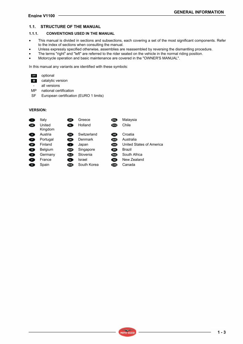
• Unless expressly specified otherwise, assemblies are reassembled by reversing the dismantling procedure. • The terms "right" and "left" are referred to the rider seated on the vehicle in the normal riding position. • Motorcycle operation and basic maintenance are covered in the "OWNER'S MANUAL". In this manual any variants are identified with these symbols:
optional catalytic version
- all versions MP national certification SF European certification (EURO 1 limits)
VERSION:
Italy Greece Malaysia
United Kingdom
Holland Chile
Austria Switzerland Croatia Portugal Denmark Australia Finland Japan United States of America Belgium Singapore Brazil Germany Slovenia South Africa France Israel New Zealand Spain South Korea Canada
GENERAL INFORMATION
1 - 4
Engine V1100
1.1.2. SAFETY WARNINGS
The symbols and warnings used throughout this manual have the following meanings:
Safety warning. This symbol appears, whether in the manual or on the vehicle itself, to indicate a personal injury hazard. Non-compliance with the indications given in the messages preceded by this symbol may result in serious risks for your and other peoples safety and for the vehicle!
DANGER Indicates a potential hazard which may result in serious injury or even death.
WARNING Indicates a potential hazard which may result in minor personal injury or damage to the vehicle.
NOTE The word "NOTE" in this manual identifies important information or instructions.
GENERAL INFORMATION
1 - 5
Engine V1100
1.2. GENERAL RULES 1.2.1. BASIC SAFETY RULES
CARBON MONOXIDE Should it be necessary to perform some operations with the vehicle running, make sure to work outdoors or in a well-aerated room. Avoid starting the engine indoors. In case you are working indoors, use a gas exhaust system.
DANGER Exhaust gases contain carbon monoxide, which is extremely toxic if inhaled and may cause loss of consciousness or even lead to death.
FUEL
DANGER The fuel used to operate engines is highly flammable and becomes explosive under particular conditions. Refuelling and engine servicing should take place in a well-ventilated area with the engine stopped. Do not smoke when refuelling or in the proximity of sources of fuel vapours, avoid flames, sparks and any element that could ignite fuel or provoke explosions. DO NOT DISPOSE OF FUEL IN THE ENVIRONMENT. KEEP AWAY FROM CHILDREN.
HIGH-TEMPERATURE COMPONENTS The engine and the components of the exhaust system become very hot and remain hot for some time after the engine has been stopped. Before handling these components, wear insulating gloves or wait until the engine and the exhaust system have cooled down. USED GEARBOX AND FORK FLUIDS
DANGER Wear latex gloves when servicing. Gearbox fluid may cause serious damage to the skin if handled daily and for long periods. Wash your hands carefully after use. Take it to the filling station where you usually buy it or to an oil salvage centre. Wear latex gloves when servicing. DO NOT DISPOSE OF FLUID IN THE ENVIRONMENT. KEEP AWAY FROM CHILDREN.
BRAKE FLUID
WARNING When handling the brake fluid, take care not to spill it on the plastic, rubber or painted parts, since it can damage them. When carrying out the maintenance operations on the braking system, use a clean cloth to cover these parts. Always wear safety goggles when working on the braking system. The brake fluid is highly irritant. Avoid contact with your eyes. If the brake fluid gets in contact with your eyes, carefully wash them with fresh water and immediately seek medical advice. KEEP AWAY FROM CHILDREN.
GENERAL INFORMATION
1 - 6
Engine V1100
HYDROGEN AND BATTERY FLUID
DANGER The battery electrolyte is a toxic, caustic substance containing sulphuric acid and thus able to cause severe burns in case of contact with the skin. Always wear tight gloves and protective clothes when handling this fluid. In case of contact with skin, rinse with plenty of fresh water. Always use a protection for your eyes since even a very small amount of the battery fluid can cause blindness. In the event of contact with your eyes, carefully wash them with water for fifteen minutes and then consult immediately an eye specialist. Should you accidentally drink some fluid, drink abundant water or milk, then drink magnesia milk or vegetable oil and immediately seek medical advice. The battery gives off explosive gases and must be kept away from flames and sources of ignition or heat; do not smoke near the battery. Make sure the room is well-aerated when servicing or recharging the battery. KEEP AWAY FROM CHILDREN. The battery fluid is corrosive. Do not spill it, especially on plastic parts. Make sure that the electrolyte acid is suitable for the type of battery used.
GENERAL PRECAUTIONS AND INFORMATION Follow these instructions closely when repairing, disassembling or reassembling the motorcycle or its components.
DANGER Using bare flames is strictly forbidden when working on the motorcycle. Before servicing or inspecting the motorcycle: stop the engine and remove the key from the ignition switch; allow for the engine and exhaust system to cool down; where possible, lift the motorcycle using adequate equipment placed on firm and level ground. Be careful of any parts of the engine or exhaust system which may still be hot to the touch to avoid scalds or burns. Do not put any vehicle parts into your mouth: vehicle components are not edible and some of them are harmful or even toxic. Unless expressly specified otherwise, assemblies are reassembled by reversing the dismantling procedure. Where a procedure is cross-referred to relevant sections in the manual, proceed sensibly to avoid disturbing any parts unless strictly necessary. Do not polish matt-painted surfaces with polishing paste. Never use fuel instead of solvent to clean the motorcycle. Do not clean any rubber or plastic parts or the seat with alcohol, petrol or solvents. Clean with water and mild detergent. Always disconnect the battery negative (-) lead before soldering any electrical components. When two or more persons service the same motorcycle together, special care must be taken to avoid personal injury. For further warnings, see (DANGEROUS ELEMENTS)
BEFORE DISASSEMBLING ANY COMPONENTS • Clean off all dirt, mud, and dust and clear any foreign objects from the vehicle before disassembling any
components. • Use the model-specific special tools where specified. DISASSEMBLING THE COMPONENTS - Never use pliers or similar tools to slacken and/or tighten nuts and bolts. Always use the suitable spanner. - Mark all connections (hoses, wiring, etc.) with their positions before disconnecting them. Identify each connection
using a distinctive symbol or convention. - Mark each part clearly to avoid confusion when refitting. - Thoroughly clean and wash any components you have removed using a detergent with low flash point. - Mated parts should always be refitted together. These parts will have seated themselves against one another in
service as a result of normal wear and tear and should never be mixed up with other similar parts on refitting. - Certain components are matched-pair parts and should always be replaced as a set. - Keep away from heat sources.

GENERAL INFORMATION
1 - 7
Engine V1100
REASSEMBLING THE COMPONENTS
DANGER Never reuse a circlip or snap ring. These parts must always be renewed once they have been disturbed. When fitting a new circlip or snap ring, take care to move the open ends apart just enough to allow fitment to the shaft. Make it a rule to check that a newly-fitted circlip or snap ring has located fully into its groove. Never clean a bearing with compressed air.
NOTE All bearings must rotate freely with no hard spots or noise. Replace any bearings that do not meet these requirements.
- Use GENUINE Moto Guzzi spare parts only. - Use the specified lubricants and consumables. - Where possible, lubricate a part before assembly. - When tightening nuts and bolts, start with the largest or innermost nut/bolt and observe a cross pattern. Tighten
evenly, in subsequent steps until achieving the specified torque. - Replace any self-locking nuts, gaskets, seals, circlips or snap rings, O-rings, split pins, bolts and screws which have
a damaged thread. - Lubricate the bearings abundantly before assembly. - Make it a rule to check that all components you have fitted are correctly in place. - After repairing the motorcycle and after each service inspection, perform the preliminary checks, and then test ride
the motorcycle in a private estate area or in a safe area away from traffic. - Clean all mating surfaces, oil seal edges and gaskets before assembly. Apply a thin layer of lithium grease along the
edges of oil seals. Fit oil seals and bearings with the marking or serial number facing outwards (in view). ELECTRICAL CONNECTORS To disconnect the electrical connectors, follow the procedures below. Failure to comply with these procedures may lead to irreparable damage to the connector and the wiring as well. If present, press the special safety hooks.
WARNING Do not pull cables to disconnect the two connectors.
• Grasp the two connectors and disconnect them by pulling them in the two opposite directions. • In case of dirt, rust, moisture, etc.., thoroughly clean the inside of the connectors with compressed air. • Make sure that the cables are correctly fitted inside the connector terminals.
NOTE The two connectors have just one correct positioning. Make sure to position them in the right direction.
• Then fit the two connectors. Make sure they are correctly coupled (a click will be heard if hooks are present). TIGHTENING TORQUE SETTINGS
DANGER Always remember that the tightening torque settings of all wheel, brake, wheel shaft and other suspension parts fasteners play a fundamental role to ensure vehicle safety. Make sure that these values are always within the specified limits. Check fastening parts tightening torque settings at regular intervals. Upon reassembly, always use a torque wrench. Failure to comply with these recommendations could lead to the loosening and detachment of one of these parts with a consequent locking of the wheel or other serious troubles affecting the vehicle manoeuvrability, and thus the risk of falls and serious injuries or death.

GENERAL INFORMATION
1 - 8
Engine V1100
1.3. DANGEROUS ELEMENTS 1.3.1. WARNINGS
FUEL
DANGER The fuel used to operate engines is highly flammable and becomes explosive under particular conditions. Refuelling and engine servicing should take place in a well-ventilated area with the engine stopped. Do not smoke when refuelling or in the proximity of sources of fuel vapours, avoid flames, sparks and any element that could ignite fuel or provoke explosions. Take care not to spill fuel out of the filler, or it may ignite when in contact with hot engine parts. In the event of accidental fuel spillage, make sure the affected area is fully dry before starting the engine. Fuel expands from heat and when left under direct sunlight. Never fill the fuel tank up to the brim. Tighten the filler cap securely after each refuelling. Avoid contact with skin. Do not inhale vapours. Do not swallow fuel. Do not transfer fuel between different containers using a hose. DO NOT DISPOSE OF FUEL IN THE ENVIRONMENT. KEEP AWAY FROM CHILDREN.
Use only premium grade unleaded petrol, min. O.N. 95 (RON) and 85 (MON). LUBRICANTS
DANGER A good lubrication ensures the vehicle safety. Failure to keep the lubricants at the recommended level or the use of a non-suitable new and clean type of lubricant can lead to the engine or gearbox seizure, thus causing serious accidents, personal injury or even death. Gearbox fluid may cause serious damage to the skin if handled daily and for long periods. Wash your hands carefully after use. Do not dispose of oil in the environment. Take it to the filling station where you usually buy it or to an oil salvage centre.
WARNING When filling the vehicle with this oil, take care not to spill it out. Immediately clean spilt oil, or it might damage the vehicle paintwork. In case of contact with oil, the tyre surface will become very slippery, thus becoming a serious danger for your safety. In case of leaks, do not use the vehicle. Check and trace the cause of leaks and proceed to repair.
ENGINE OIL
DANGER Engine oil may cause serious damage to the skin if handled daily and for long periods. Wash your hands carefully after use. Do not dispose of oil in the environment. Dispose of engine oil through the nearest waste oil reclamation firm or through the supplier. Wear latex gloves when servicing.
FRONT FORK FLUID
DANGER Front suspension response can be modified to a certain extent by changing damping settings and/or selecting a particular grade of oil. Standard oil: SAE 20 W. Choose suitable viscosity grades according to the desired set-up (choose SAE 5W for a softer suspension, 20W for a stiffer suspension). The two grades can also be mixed in varying solutions to obtain the desired response.
GENERAL INFORMATION
1 - 9
Engine V1100
BRAKE FLUID
NOTE This vehicle is fitted with front and rear disc brakes. Each braking system is operated by an independent hydraulic circuit. The information provided below applies to both braking systems.
DANGER Do not use the vehicle in case brakes are worn out or do not work properly. The brakes are the parts that most ensure your safety and for this reason they must always be perfectly working. Failure to comply with these recommendations will probably lead to a crash or an accident, with a consequent risk of personal injury or death. A wet surface reduces brakes efficiency.
DANGER In case of wet ground the braking distance will be doubled, since both brakes and tyre grip on the road surface are extremely reduced by the water present on the road surface. Any water on brakes, after washing the vehicle or driving on a wet road surface or crossing puddles or gips, can wet brakes so as to greatly reduce their efficiency. Failure to comply with these recommendations may lead to serious accidents, with a consequent risk of severe personal injuries or death. Brakes are critical safety components. Do not ride the vehicle in case brakes are not working at their best. Check for brakes proper operation before every trip. Brake fluid is an irritant. Avoid contact with eyes or skin. In the event of accidental contact, wash affected body parts thoroughly. In the event of accidental contact with eyes, contact an eye specialist or seek medical advice. DO NOT RELEASE BRAKE FLUID INTO THE ENVIRONMENT. KEEP AWAY FROM CHILDREN. When handling brake fluid, take care not to spill it onto plastic or paint-finished parts or they will damage.
DANGER Do not use any brake fluids other than the specified type. Never mix different types of fluids to top up level, as this will damage the braking system. Do not use brake fluid from containers which have been kept open or in storage for long periods. Any sudden changes in play or hardness in the brake levers are warning signs of problems with the hydraulic circuits. Ensure that the brake discs and brake linings have not become contaminated with oil or grease. This is particularly important after servicing or inspections. Make sure the brake lines are not twisted or worn. Prevent accidental entering of water or dust into the circuit. Wear latex gloves when servicing the hydraulic circuit.
DISC BRAKES
DANGER The brakes are the parts that most ensure your safety and for this reason they must always be perfectly working; check them before every trip. A dirty disc soils the pads. Dirty pads must be replaced, while dirty discs must be cleaned with a high-quality degreaser. Perform the maintenance operations with half the indicated frequency if the vehicle is used in rainy or dusty areas, on uneven surfaces or for racing. Check brake pads for wear. When the brake pads wear out, the level of the fluid decreases to automatically compensate for their wear. The front brake fluid reservoir is located on the right handlebar, near the front brake lever. The rear brake fluid reservoir is located under the right fairing. Do not use the vehicle if the braking system leaks fluid.

GENERAL INFORMATION
1 - 10
Engine V1100
TYRES
WARNING If tyres are excessively inflated, the vehicle will be hard, difficult and uncomfortable to ride. In addition, the roadworthiness, mainly on wet surfaces and during cornering, will be impaired. Flat tyres (insufficient pressure) can slip on the rim and make you lose the control of the vehicle. In this case too, both vehicle roadworthiness, manoeuvrability and brake efficiency will be impaired. Tyres changing, repair, maintenance and balancing must be carried out by specialised technicians using suitable equipment. When new, tyres can have a thin slippery protective coating. Drive carefully for the first kilometres (miles). Never use rubber treating substances on tyres. In particular, avoid contact with fluid fuels, leading to a rapid wear. In case of contact with oil or fuel, do not clean but change the tyres.
DANGER Some of the factory-assembled tyres of this vehicle are provided with wear indicators. There are several kinds of wear indicators. For more information on how to check the wear, contact your Dealer. Visually check if the tyres are worn and in this case have them changed. If a tyre deflates while driving, stop immediately. Avoid hard brakings or moves and do not close throttles too abruptly. Slowly close the throttle grip, move to the edge of the road and use the engine brake to slow down until coming to a halt. Failure to comply with these recommendations may lead to accidents, with a consequent risk of personal injuries or death. Do not install tyres with air tube on rims for tubeless tyres and vice versa.

GENERAL INFORMATION
1 - 11
Engine V1100
1.4. RUNNING-IN 1.4.1. RUNNING-IN
Correct engine running-is essential to ensuring proper performance and durability. Twisty, hilly roads are ideal for an effective running-in of engine, suspension and brakes. During running-in, change speed. This will allow engine parts to be alternately loaded and unloaded, allowing them to cool down when unloaded. While it is important to put some stress on engine components during running-in, it is equally important to avoid extreme load conditions.
WARNING Only after the first 2000 km (1243 mi) of running-in is it possible to obtain the best acceleration performance from the vehicle.
Follow these recommendations: • Do not open the throttle completely if the speed is low, both during and after running-in. • Until you have covered the first 100 km (62 mi), use the brakes gently and avoid harsh, prolonged braking. This
ensures a correct bedding-in of the pads on the brake discs. • During the first 1000 km (621 mi), never exceed 5000 rpm (see table).
WARNING After the first 1000 km (621 mi), carry out the checking operations indicated in the column "After running-in", see REGULAR SERVICE INTERVALS CHART, in order to avoid hurting yourself or other people and/or damaging the vehicle.
• After the first 1000 km (621 mi) and until covering 2000 km (1243 mi), drive more briskly, varying speed and using
maximum acceleration for just a few seconds, in order to ensure better coupling of the components; never exceed 6000 rpm (see table).
• After the first 2000 km (1243 mi) you may run the engine harder, however, without exceeding the maximum rpm allowed (7600 rpm).
Recommended maximum rpm Mileage Km (mi) rpm 0÷1000 (621) 5000 1000÷2000 (621÷1243) 6000 Over 2000 (1243) 7600

GENERAL INFORMATION
1 - 12
Engine V1100
1.5. POSITION OF THE SERIAL NUMBERS 1.5.1. POSITION OF THE SERIAL NUMBERS
These numbers are necessary for the registration of the vehicle.
NOTE Do not alter the identification numbers if you do not want to incur severe penal and administrative sanctions; in particular, altering the frame number voids the warranty.
ENGINE NUMBER The engine number is stamped on the left side, close to engine oil level plug.

TECHNICAL INFORMATION
2 - 1
Engine V1100
TECHNICAL INFORMATION 2

TECHNICAL INFORMATION
2 - 2
Engine V1100
SUMMARY 2.1. TECHNICAL INFORMATION............................................................................................................................ 3
2.1.1. TECHNICAL DATA.................................................................................................................................... 3 2.1.2. LUBRICANT TABLE .................................................................................................................................. 4 2.1.3. TIGHTENING TORQUE SETTINGS ......................................................................................................... 5 2.1.4. SPECIAL TOOLS ...................................................................................................................................... 7

TECHNICAL INFORMATION
2 - 3
Engine V1100
2.1. TECHNICAL INFORMATION 2.1.1. TECHNICAL DATA
ENGINE Type twin-cylinder, 90° V transversal, 4-stroke engine Number of cylinders two Cylinder arrangement V, 90° Total displacement 1064 cu cm (65 cu in) Bore/stroke 92 x 80 mm (3.6 x 3.1 in). Compression ratio 9.6 : 1 Starting electric Engine idling speed 1100 ± 100 rpm Clutch single plate, dry clutch with cush drive damper Lubricating system System under pressure, adjustment by valves and vane pump Air filter cartridge, dry Cooling system air cooled CAPACITIES Engine oil Engine oil and oil filter change 3600 cu. cm (219 cu in) Gearbox fluid 500 cu cm (30.5 cu in) Transmission fluid 380 cu cm (23.2 cu in) TIMING SYSTEM Timing diagram: 2 valves, with rods and rocker arms Values with inspection clearance between rocker arms and valve
intake 0.10 mm (0.0039 in.) exhaust 0.15 mm (0.0059 in.)
TRANSMISSION SYSTEM primary drive gear, ratio: 26/35 = 1:1.3461 gearbox Mechanic, with 6 speeds, controlled by a pedal on engine left side overall gear ratios: 1st gear 17/38 = 1:2.2353 2nd gear 20/34 = 1:1.7 3rd gear 23/31 = 1:1.3478 4th gear 26/29 = 1:1.1154 5th gear 31/30 = 1:0.9677 final drive with cardan joint ratio 12/44 = 1:3.6667 FUEL SYSTEM Type Electronic injection (Weber Marelli) with stepper motor Choke Ø 36 mm (1.417 in.) Fuel Premium grade unleaded petrol, minimum octane rating 95 (RON) and
85 (MON). SPARK PLUGS Internal (long life) NGK PMR8B External NGK BPR6ES Electrode gap 0.6 0.7 mm (0.024 0.028 in.)
TECHNICAL INFORMATION
2 - 4
Engine V1100
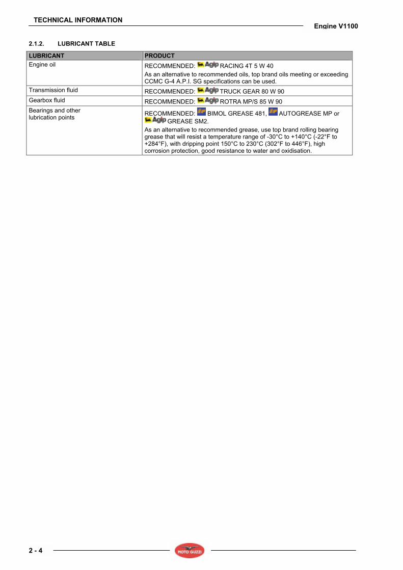
2.1.2. LUBRICANT TABLE
LUBRICANT PRODUCT Engine oil RECOMMENDED: RACING 4T 5 W 40
As an alternative to recommended oils, top brand oils meeting or exceeding CCMC G-4 A.P.I. SG specifications can be used.
Transmission fluid RECOMMENDED: TRUCK GEAR 80 W 90 Gearbox fluid RECOMMENDED: ROTRA MP/S 85 W 90 Bearings and other lubrication points RECOMMENDED: BIMOL GREASE 481, AUTOGREASE MP or
GREASE SM2. As an alternative to recommended grease, use top brand rolling bearing grease that will resist a temperature range of -30°C to +140°C (-22°F to +284°F), with dripping point 150°C to 230°C (302°F to 446°F), high corrosion protection, good resistance to water and oxidisation.

TECHNICAL INFORMATION
2 - 5
Engine V1100
2.1.3. TIGHTENING TORQUE SETTINGS
DESCRIPTION
QU
AN
TITY
SCR
EW /
NU
T
TIG
HTE
NIN
G
TOR
QU
E
(N
m)
Not
e
HEAD UNIT head taper cap 6 4
stud bolt M8x42 4 M8 35
adjuster 4 / / /
Nut 4 8-11
Hex.head screw DA M6x16 4 M6 6-8
stainl.st. TBEI screw M6x25 16 M6 10
stainl.st.flanged TBEI screw M5x16 4 M5 6-7
oil/head temperature sensor M12x1.5 1 M12 10-12
head temperature sensor casing M10x1.5 1 M10 10-12
TIMING UNIT
Hex.head screw DA M6x20 3 M6 8-12
nut M18x1.5 1 M18 150
belt tension 50
LOCKS
stud bolt M10x35 2 M10 40
Linkage 1 42
nut EA ZB M10x1.5 2 M10 40-42
head bolt 1 40-42
stud bolt M8x75 2 M8 35
stud bolt M8x66 1 M8 35
Hex.head screw DA M8x25 2 M8 25
Flathead Allen screw M4x8 UNI 5933 1 M4 5
TCEI screw M4x10 2 M4 5
Hex.head screw DA M8x25 1 M8 25
TCEI screw DA M6x30 2 M6 8-12
TCEI screw DA M8x55 cl. 8.8 UNI 5931 dacromet 1 M8 23
TCEI screw M6x16 2 M6 8-12
TCEI screw DA M6x30 1 M6 8-12
TCEI screw DA M6x40 2 M6 8-12
TCEI screw DA M6x60 1 M6 8-12
fitting M24x1.5 2 M24 40
TCEI screw DA M6x55 1 M6 8-12
TCEI screw DA M6x20 2 M6 8-12
copper line nipples M18x1.5 1 M18 20
plug with rod 2 / / /
magnetic plug M10x1.5 1 M10 20

TECHNICAL INFORMATION
2 - 6
Engine V1100
DESCRIPTION
QU
AN
TITY
SCR
EW /
NU
T
TIG
HTE
NIN
G
TOR
QU
E
(N
m)
Not
e
LUBRICATION UNIT
TCEI screw DA M8x30 4 M8 25
drilled screw M8x1.25 1 M8 15-18
plug M18x1.5 1 M18 40
plug M32x1.5 1 M32 40
CRANKSHAFT UNIT
connecting rod screw 2 60÷62
nut EBFM ZB MF25x1.5 1 M25 120
FRAME UNIT ON ENGINE
TCEI screw DA M6x40 2 M6 8-12
reduction 4 20
IGNITION UNIT
TCEI screw DA M8x45 1 M8 22
TCEI screw DA M10x60 1 M10 see nut
nut M10x1.5 flanged 1 M10 30
TBEI screw DA M8x50 1 M8 / / /
nut EBFM DA MF16x1.5 1 M16 80
spark plug NGK BPR 6ES 2 20-30
spark plug PMR8b 2 13-15
TCEI screw M6x16 4 M6 8-12
FUEL FEED CONTROL UNIT
TCEI screw M5x12 2 M5 6-7
stainl.st.flanged TBEI screw M5x16 2 M5 6-7
TCEI screw DA M6x25 6 M6 8-12
GEAR SHIFT UNIT
Screws securing clutch housing to gearbox 14 M6 13
Screws securing bearing to clutch housing 3 M6 10
Clutch housing stop screws 1 M8 24
Ring nut on clutch shaft 1 M22x1 100
Neutral sensor on gearbox 1 M8x1 10
Magnetic plug 1 M10 24
Oil filler cap 1 M18x1.5 28
Union for breather hose 1 M10 8

TECHNICAL INFORMATION
2 - 7
Engine V1100
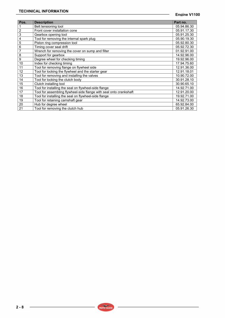
2.1.4. SPECIAL TOOLS
Suitable special tools are necessary for correctly removing, refitting and adjusting. Unsuitable tools and/or improvised procedures could cause damages that might be avoided if the special tools are used. Following are the special tools especially designed for this vehicle. If necessary, request the general special tools.
TECHNICAL INFORMATION
2 - 8
Engine V1100
Pos. Description Part no. 1 Belt tensioning tool 05.94.86.30 2 Front cover installation cone 05.91.17.30 3 Gearbox opening tool 05.91.25.30 4 Tool for removing the internal spark plug 05.90.19.30 5 Piston ring compression tool 05.92.80.30 6 Timing cover seal drift 05.92.72.30 7 Wrench for removing the cover on sump and filter 01.92.91.00 8 Support for gearbox 14.92.96.00 9 Degree wheel for checking timing 19.92.96.00 10 Index for checking timing 17.94.75.60 11 Tool for removing flange on flywheel side 12.91.36.00 12 Tool for locking the flywheel and the starter gear 12.91.18.01 13 Tool for removing and installing the valves 10.90.72.00 14 Tool for locking the clutch body 30.91.28.10 15 Clutch installing tool 30.90.65.10 16 Tool for installing the seal on flywheel-side flange 14.92.71.00 17 Tool for assembling flywheel-side flange with seal onto crankshaft 12.91.20.00 18 Tool for installing the seal on flywheel-side flange 19.92.71.00 19 Tool for retaining camshaft gear 14.92.73.00 20 Hub for degree wheel 65.92.84.00 21 Tool for removing the clutch hub 05.91.26.30

ENGINE
3 - 1
Engine V1100
ENGINE 3

ENGINE
3 - 2
Engine V1100
SUMMARY 3.1. REMOVING THE ACCESSORIES ................................................................................................................... 3
3.1.1. REMOVING THE STARTER MOTOR ....................................................................................................... 3 3.1.2. REMOVING THE BLOW-BY SYSTEM...................................................................................................... 4
3.2. GENERATOR ................................................................................................................................................... 6 3.2.1. REMOVING THE GENERATOR ............................................................................................................... 6 3.2.2. INSTALLATION ....................................................................................................................................... 10
3.3. TIMING SYSTEM............................................................................................................................................ 14 3.3.1. REMOVAL AND INSTALLATION ............................................................................................................ 14 3.3.2. TECHNICAL DATA.................................................................................................................................. 18 3.3.3. TIMING .................................................................................................................................................... 19 3.3.4. MEASURING THE SENSOR GAP .......................................................................................................... 21
3.4. OIL PUMP....................................................................................................................................................... 23 3.4.1. REMOVING THE OIL PUMP................................................................................................................... 23
3.5. HEADS ........................................................................................................................................................... 24 3.5.1. REMOVING THE HEAD COVERS .......................................................................................................... 24 3.5.2. REMOVING THE HEADS........................................................................................................................ 25 3.5.3. CHECKING THE COMPONENTS ........................................................................................................... 30 3.5.4. REASSEMBLING THE HEADS ............................................................................................................... 32
3.6. CYLINDERS AND PISTONS .......................................................................................................................... 37 3.6.1. REMOVAL, CHECK AND INSTALLATION.............................................................................................. 37
3.7. FLYWHEEL..................................................................................................................................................... 42 3.7.1. REMOVAL, CHECK AND REASSEMBLY............................................................................................... 42
3.8. CRANKSHAFT AND CONNECTING RODS................................................................................................... 44 3.8.1. REMOVAL ............................................................................................................................................... 44 3.8.2. CHECK .................................................................................................................................................... 46 3.8.3. REASSEMBLY ........................................................................................................................................ 49
3.9. OIL SUMP....................................................................................................................................................... 50 3.9.1. REMOVAL, CHECK AND REASSEMBLY............................................................................................... 50

ENGINE
3 - 3
Engine V1100
3.1. REMOVING THE ACCESSORIES 3.1.1. REMOVING THE STARTER MOTOR
• Loosen and remove the two screws and collect the washers.
• Slide out the starter motor.
ENGINE
3 - 4
Engine V1100
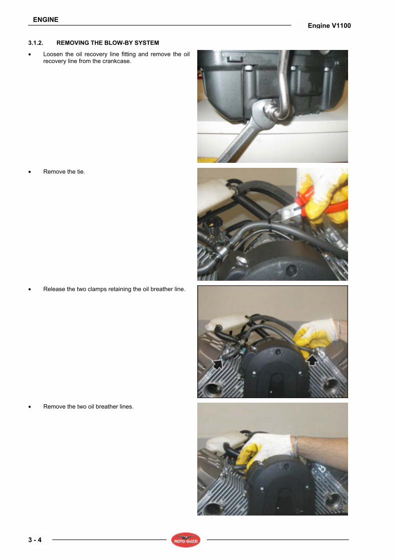
3.1.2. REMOVING THE BLOW-BY SYSTEM
• Loosen the oil recovery line fitting and remove the oil recovery line from the crankcase.
• Remove the tie.
• Release the two clamps retaining the oil breather line.
• Remove the two oil breather lines.

ENGINE
3 - 5
Engine V1100
• Loosen and remove the oil recovery line positioning screw.
• Release the oil recovery line.
• Remove the complete blow-by system.
ENGINE
3 - 6
Engine V1100
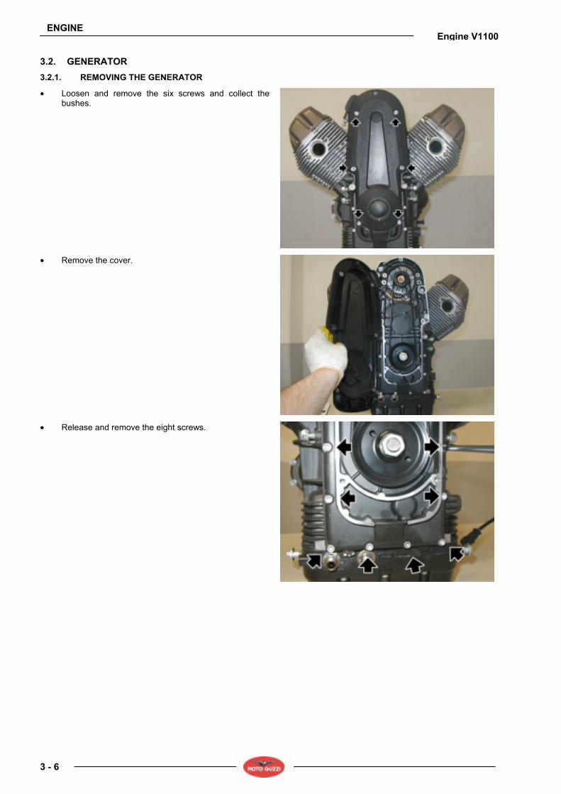
3.2. GENERATOR 3.2.1. REMOVING THE GENERATOR
• Loosen and remove the six screws and collect the bushes.
• Remove the cover.
• Release and remove the eight screws.

ENGINE
3 - 7
Engine V1100
• Release and remove the two screws.
• Loosen the nut and collect the screw.
• Loosen the screw.
• Loosen the nut and release the adjuster, so that generator can slide down.

ENGINE
3 - 8
Engine V1100
• Completely unscrew and remove the screw.
• Remove the belt and the generator complete with pulley.
• Using an air gun, loosen and remove the nut and collect the spacer.
• Slide out the lower pulley.
• Release and remove the two screws.

ENGINE
3 - 9
Engine V1100
• Remove the generator subframe. • Remove the seal, if necessary.
ENGINE
3 - 10
Engine V1100
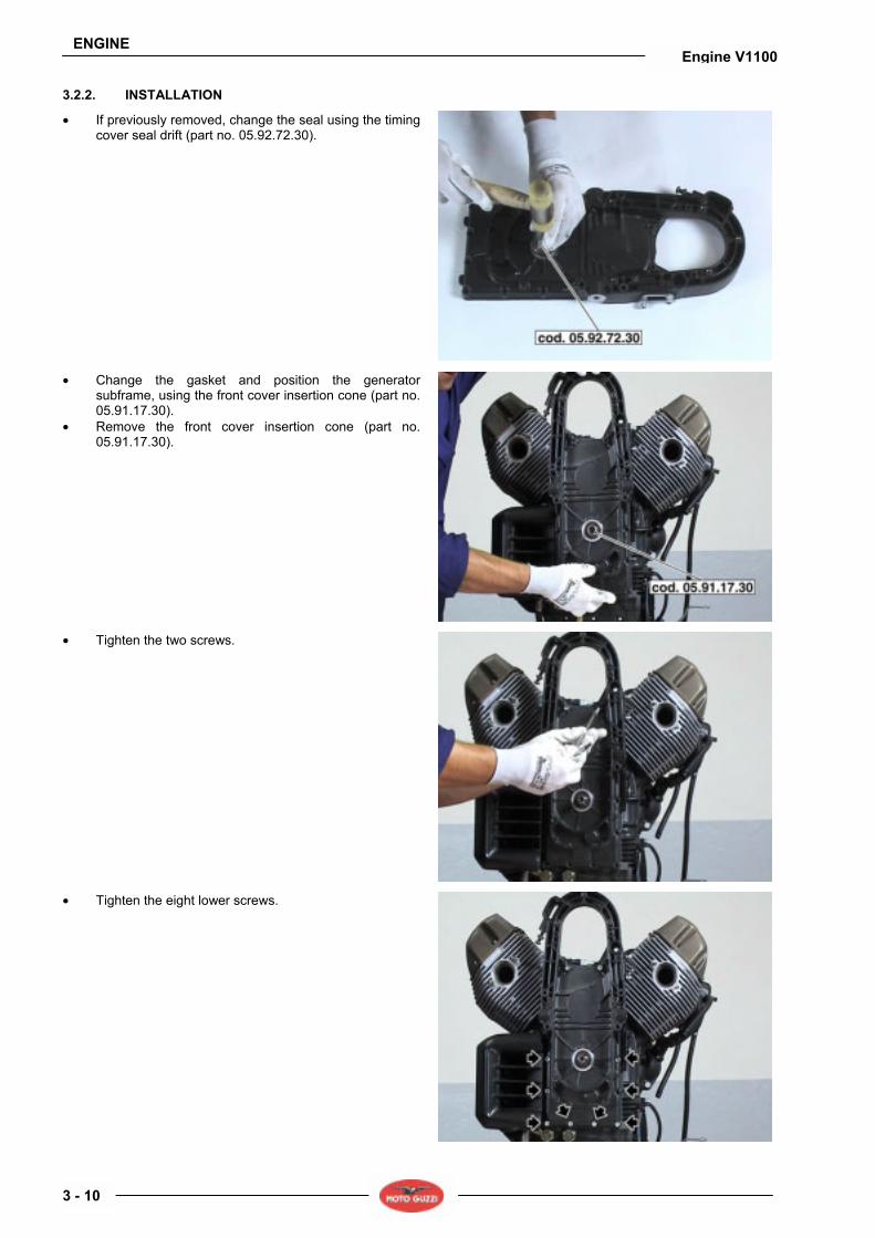
3.2.2. INSTALLATION
• If previously removed, change the seal using the timing cover seal drift (part no. 05.92.72.30).
• Change the gasket and position the generator subframe, using the front cover insertion cone (part no. 05.91.17.30).
• Remove the front cover insertion cone (part no. 05.91.17.30).
• Tighten the two screws.
• Tighten the eight lower screws.

ENGINE
3 - 11
Engine V1100
• Tighten the ten screws; proceed in steps and in a cross pattern.
• Position the lower pulley and the spacer. • Tighten the nut to the specified torque.
• Position the generator and the timing belt.
• Position the screw and tighten it.

ENGINE
3 - 12
Engine V1100
• Position the screw and nut and tighten them.
• Using the belt tensioning tool, tension the belt to the specified value and tighten the adjuster.
• Remove the belt tensioning tool.
• Tighten the lock nut.
• Tighten the generator retaining screws.

ENGINE
3 - 13
Engine V1100
• Tighten the four screws; proceed in steps and in a cross pattern.
• Fit the timing cover.
• Tighten the five screws; proceed in steps and in a cross pattern.

ENGINE
3 - 14
Engine V1100
3.3. TIMING SYSTEM 3.3.1. REMOVAL AND INSTALLATION
REMOVAL • Remove the engine from the frame, see chassis
manual, see (REFERENCE MANUALS). • Remove the generator following the instructions given
in (REMOVAL). • Remove both heads, see (REMOVING THE HEADS). • Mark the timing references to be restored upon
reassembly.
• Using the suitable tool (part no. 12.91.18.01) lock the starter gear.
• Loosen the central nut securing the camshaft gear and collect the washer.
ENGINE
3 - 15
Engine V1100
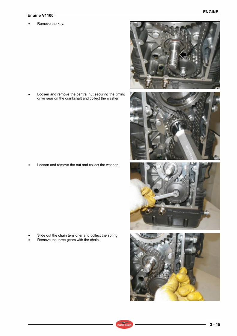
• Remove the key.
• Loosen and remove the central nut securing the timing drive gear on the crankshaft and collect the washer.
• Loosen and remove the nut and collect the washer.
• Slide out the chain tensioner and collect the spring. • Remove the three gears with the chain.

ENGINE
3 - 16
Engine V1100
• Slide out the pick-up ring and collect the dowel.
• Loosen and remove the three screws and collect the washers.
• Slide out the flange.
• Slide out the tappets from their seats on either side.

ENGINE
3 - 17
Engine V1100
• Slide out the camshaft.
REASSEMBLY
NOTE For refitting the timing system, suitably heat the engine with a heater to be able to correctly fit the camshaft avoiding damages.
• Follow the removal instructions in reverse order.
ENGINE
3 - 18
Engine V1100
3.3.2. TECHNICAL DATA
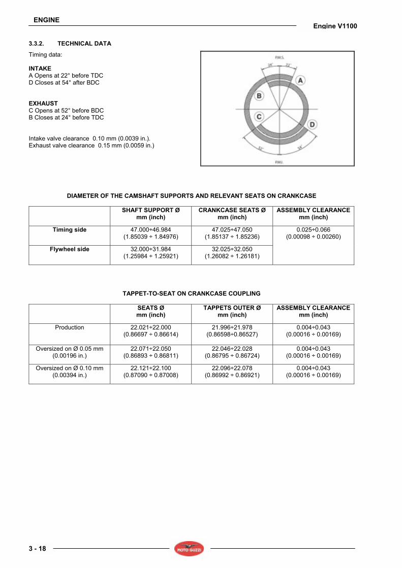
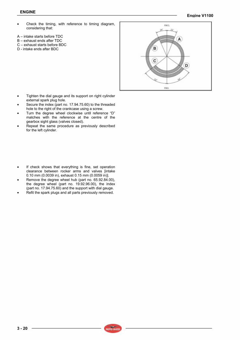
Timing data: INTAKE A Opens at 22° before TDC D Closes at 54° after BDC EXHAUST C Opens at 52° before BDC B Closes at 24° before TDC Intake valve clearance 0.10 mm (0.0039 in.). Exhaust valve clearance 0.15 mm (0.0059 in.)
DIAMETER OF THE CAMSHAFT SUPPORTS AND RELEVANT SEATS ON CRANKCASE
SHAFT SUPPORT Ø mm (inch)
CRANKCASE SEATS Ø mm (inch)
ASSEMBLY CLEARANCE mm (inch)
Timing side 47.000÷46.984 (1.85039 ÷ 1.84976)
47.025÷47.050 (1.85137 ÷ 1.85236)
Flywheel side 32.000÷31.984 (1.25984 ÷ 1.25921)
32.025÷32.050 (1.26082 ÷ 1.26181)
0.025÷0.066 (0.00098 ÷ 0.00260)
TAPPET-TO-SEAT ON CRANKCASE COUPLING
SEATS Ø mm (inch)
TAPPETS OUTER Ø mm (inch)
ASSEMBLY CLEARANCE mm (inch)
Production 22.021÷22.000 (0.86697 ÷ 0.86614)
21.996÷21.978 (0.86598÷0.86527)
0.004÷0.043 (0.00016 ÷ 0.00169)
Oversized on Ø 0.05 mm (0.00196 in.)
22.071÷22.050 (0.86893 ÷ 0.86811)
22.046÷22.028 (0.86795 ÷ 0.86724)
0.004÷0.043 (0.00016 ÷ 0.00169)
Oversized on Ø 0.10 mm (0.00394 in.)
22.121÷22.100 (0.87090 ÷ 0.87008)
22.096÷22.078 (0.86992 ÷ 0.86921)
0.004÷0.043 (0.00016 ÷ 0.00169)
ENGINE
3 - 19
Engine V1100
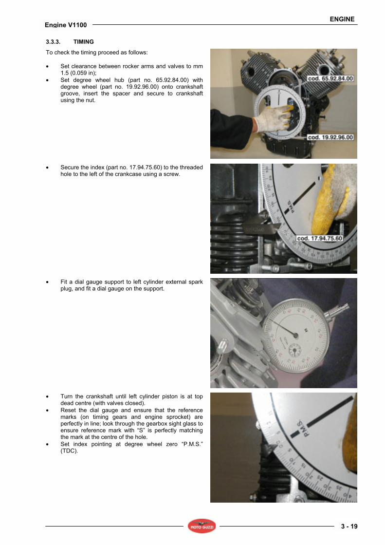
3.3.3. TIMING
To check the timing proceed as follows: • Set clearance between rocker arms and valves to mm
1.5 (0.059 in); • Set degree wheel hub (part no. 65.92.84.00) with
degree wheel (part no. 19.92.96.00) onto crankshaft groove, insert the spacer and secure to crankshaft using the nut.
• Secure the index (part no. 17.94.75.60) to the threaded hole to the left of the crankcase using a screw.
• Fit a dial gauge support to left cylinder external spark plug, and fit a dial gauge on the support.
• Turn the crankshaft until left cylinder piston is at top dead centre (with valves closed).
• Reset the dial gauge and ensure that the reference marks (on timing gears and engine sprocket) are perfectly in line; look through the gearbox sight glass to ensure reference mark with S is perfectly matching the mark at the centre of the hole.
• Set index pointing at degree wheel zero P.M.S. (TDC).
ENGINE
3 - 20
Engine V1100
• Check the timing, with reference to timing diagram, considering that:
A intake starts before TDC B exhaust ends after TDC C exhaust starts before BDC D - intake ends after BDC
• Tighten the dial gauge and its support on right cylinder external spark plug hole.
• Secure the index (part no. 17.94.75.60) to the threaded hole to the right of the crankcase using a screw.
• Turn the degree wheel clockwise until reference D matches with the reference at the centre of the gearbox sight glass (valves closed).
• Repeat the same procedure as previously described for the left cylinder.
• If check shows that everything is fine, set operation clearance between rocker arms and valves [intake 0.10 mm (0.0039 in), exhaust 0.15 mm (0.0059 in)].
• Remove the degree wheel hub (part no. 65.92.84.00), the degree wheel (part no. 19.92.96.00), the index (part no. 17.94.75.60) and the support with dial gauge.
• Refit the spark plugs and all parts previously removed.
ENGINE
3 - 21
Engine V1100
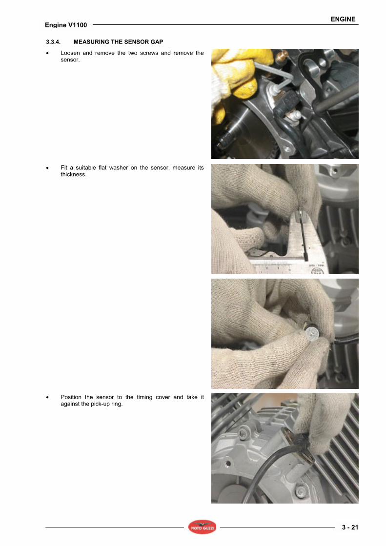
3.3.4. MEASURING THE SENSOR GAP
• Loosen and remove the two screws and remove the sensor.
• Fit a suitable flat washer on the sensor, measure its thickness.
• Position the sensor to the timing cover and take it against the pick-up ring.

ENGINE
3 - 22
Engine V1100
• Measure the clearance between plate and cover using a feeler gauge. Take the flat washer thickness from this value to determine the gap between sensor and pick-up ring.
• Remove the washer, smear the plate with suitable sealant, fit the sensor and tighten the screws to the specified torque.

ENGINE
3 - 23
Engine V1100
3.4. OIL PUMP 3.4.1. REMOVING THE OIL PUMP
• Drain all engine oil. • Remove the generator, see (REMOVING THE
GENERATOR). • Remove the timing system, see (REMOVING THE
TIMING SYSTEM). • Loosen and remove the four oil pump securing screws
(A). • Remove the oil pump (B).

ENGINE
3 - 24
Engine V1100
3.5. HEADS 3.5.1. REMOVING THE HEAD COVERS
NOTE The following procedure applies to both head covers.
• Loosen and remove the eight screws and collect the bushes.
• Remove the head cover and collect the gasket.
NOTE Repeat the same procedure above described in reverse order to refit the head cover.
Upon reassembly, change the head cover gasket.
ENGINE
3 - 25
Engine V1100
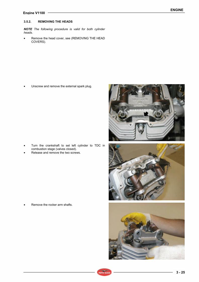
3.5.2. REMOVING THE HEADS
NOTE The following procedure is valid for both cylinder heads.
• Remove the head cover, see (REMOVING THE HEAD COVERS).
• Unscrew and remove the external spark plug.
• Turn the crankshaft to set left cylinder to TDC in combustion stage (valves closed).
• Release and remove the two screws.
• Remove the rocker arm shafts.
ENGINE
3 - 26
Engine V1100
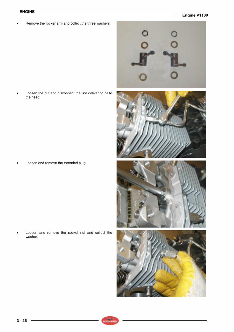
• Remove the rocker arm and collect the three washers.
• Loosen the nut and disconnect the line delivering oil to the head.
• Loosen and remove the threaded plug.
• Loosen and remove the socket nut and collect the washer.
ENGINE
3 - 27
Engine V1100
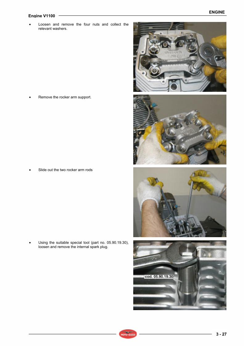
• Loosen and remove the four nuts and collect the relevant washers.
• Remove the rocker arm support.
• Slide out the two rocker arm rods
• Using the suitable special tool (part no. 05.90.19.30), loosen and remove the internal spark plug.
ENGINE
3 - 28
Engine V1100
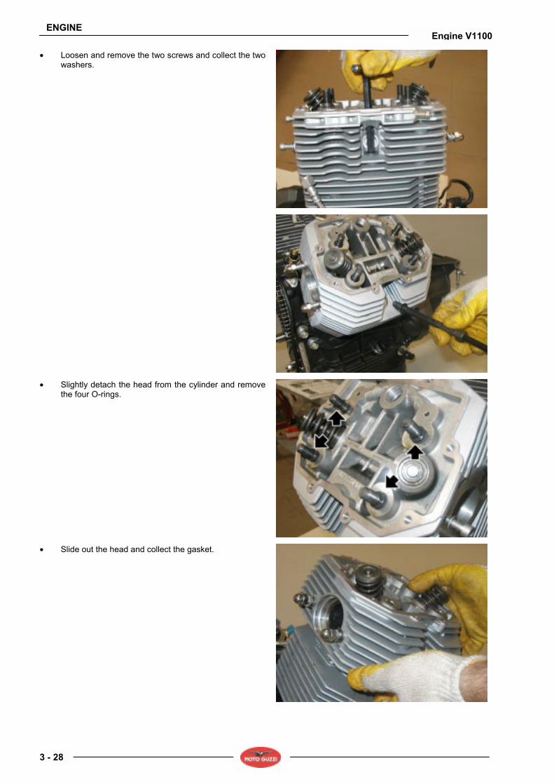
• Loosen and remove the two screws and collect the two washers.
• Slightly detach the head from the cylinder and remove the four O-rings.
• Slide out the head and collect the gasket.

ENGINE
3 - 29
Engine V1100
• Fit the special tool (part no. 10.90.72.00) to top retainer and at the centre of the valve to be removed.
• Tighten the tool screw until it starts pulling, then tap with a mallet on tool head (working on top retainer) so to detach the two valve cotters (1) from top plate (2).
• Once the two valve cotters (1) are detached, screw in until they can be removed from their seats on the valves; loosen the tool and remove it.
• Slide out the top retainer (2). • Remove the internal spring (3). • Remove the external spring (4). • Remove the bottom retainer (5) and the shims, if
necessary. • Remove valve (6) from inside the head.
ENGINE
3 - 30
Engine V1100
3.5.3. CHECKING THE COMPONENTS
HEADS Ensure that: • Surfaces mating with cover and cylinder are not so
scratched or damaged to compromise sealing. • Check that clearance between valve guide hole and
valve stem is within recommended limit. • Check valve seat condition. VALVE GUIDES
Use a drift to remove the valve guides from the heads. The valve guides shall be changed only if clearance between them and the valve stem can not be eliminated by changing the valves only. Proceed as follows to fit the valve guides to the head: • Heat up the head in an oven to about 60°C (140°F). • Lubricate the valve guides. • Fit the circlips. • Press the valve guides using a drift. • Using a bore reamer, grind the holes where valve stem
slides, taking the inner diameter to the specified value. Interference fit of seat on the head and valve guide should be 0.046 ÷ 0.075 mm (0.0018 ÷ 0.0030 in).
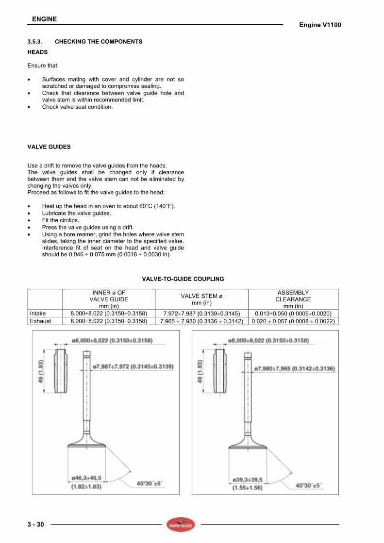
VALVE-TO-GUIDE COUPLING
INNER ø OF
VALVE GUIDE mm (in)
VALVE STEM ø mm (in)
ASSEMBLY CLEARANCE
mm (in) Intake 8.000÷8.022 (0.3150÷0.3158) 7.972÷7.987 (0.3139÷0.3145) 0.013÷0.050 (0.0005÷0.0020) Exhaust 8.000÷8.022 (0.3150÷0.3158) 7.965 ÷ 7.980 (0.3136 ÷ 0.3142) 0.020 ÷ 0.057 (0.0008 ÷ 0.0022)

ENGINE
3 - 31
Engine V1100
VALVE SEATS Grind the valve seats with a cutter. Seat slant angle is 45°± 5. After milling, grind to ensure correct coupling and perfect sealing between valve head and ring nut.
INTAKE VALVE SEAT DETAIL VIEW
EXHAUST VALVE SEAT DETAIL VIEW

ENGINE
3 - 32
Engine V1100
3.5.4. REASSEMBLING THE HEADS
NOTE The following procedure applies to both cylinder heads.
• Refit valve (6) inside the head. • Fit the bottom retainer (5) and the shims. • Refit the external spring (4). • Refit the internal spring (3). • Fit the top retainer (2). • Position the two valve cotters (1) in their seats on the
valves. • Compress the spring with the suitable tool (part no.
10907200), then install the valve cotters.
• Remove the special tool (part no. 10.90.72.00)
• Change the cylinder-head gasket. • Install the head.
• Change the four O-rings.
ENGINE
3 - 33
Engine V1100
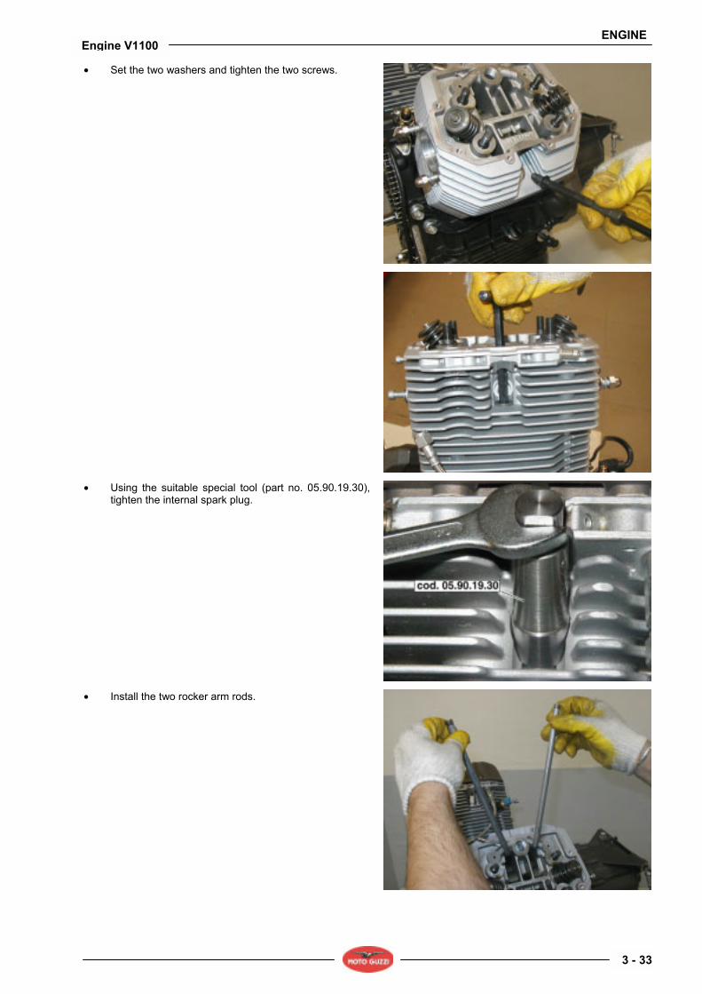
• Set the two washers and tighten the two screws.
• Using the suitable special tool (part no. 05.90.19.30), tighten the internal spark plug.
• Install the two rocker arm rods.
ENGINE
3 - 34
Engine V1100
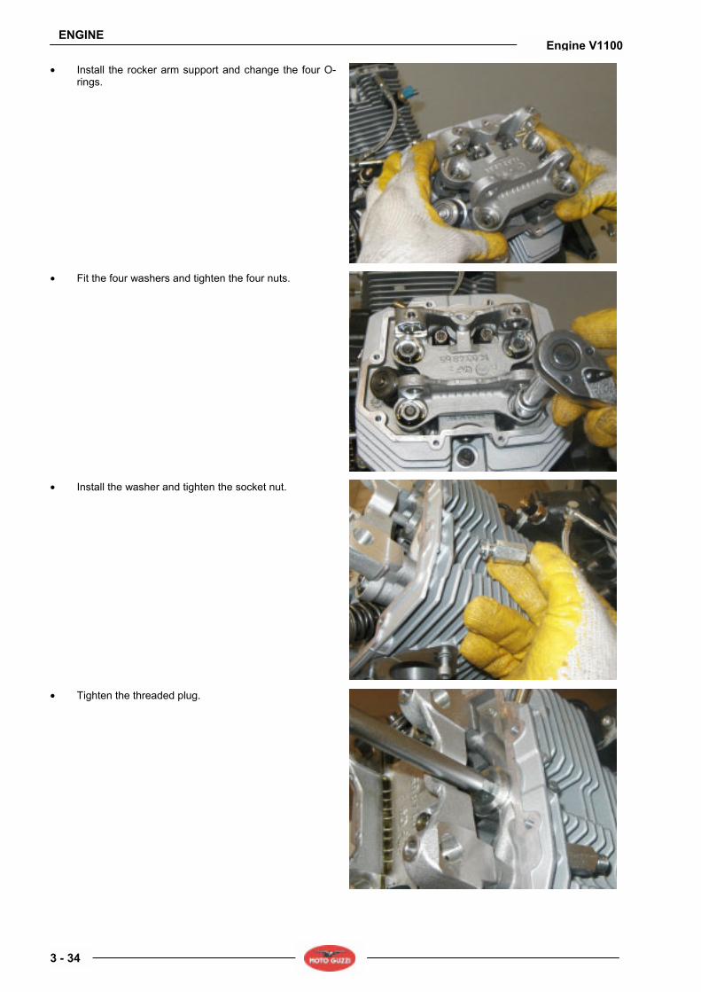
• Install the rocker arm support and change the four O-rings.
• Fit the four washers and tighten the four nuts.
• Install the washer and tighten the socket nut.
• Tighten the threaded plug.

ENGINE
3 - 35
Engine V1100
• Connect the line delivering oil to the head and tighten the nut.
• Fit the six washers and install the rocker arms.
• Install the rocker arm shafts.
• Turn the crankshaft to set left cylinder to TDC in combustion stage (valves closed).
• Tighten the two screws.
ENGINE
3 - 36
Engine V1100
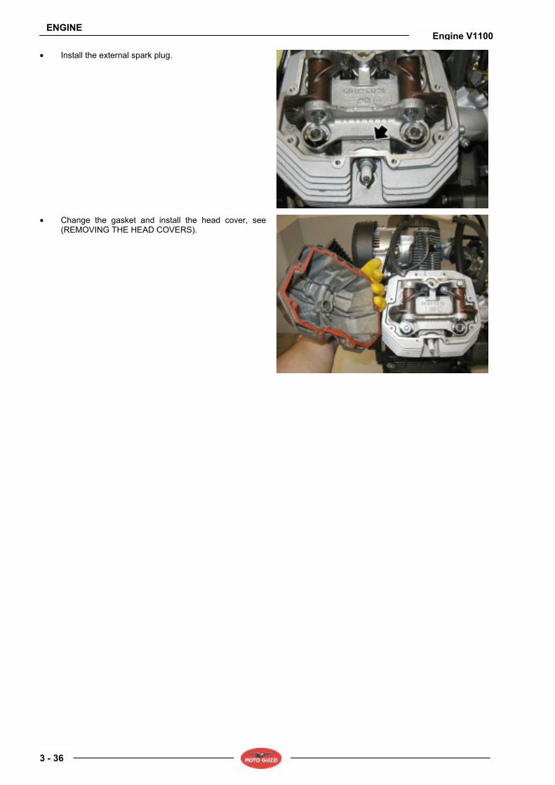
• Install the external spark plug.
• Change the gasket and install the head cover, see (REMOVING THE HEAD COVERS).

ENGINE
3 - 37
Engine V1100
3.6. CYLINDERS AND PISTONS 3.6.1. REMOVAL, CHECK AND INSTALLATION
NOTE The following procedure applies to both cylinder heads.
REMOVAL • Remove the head, see (REMOVING THE HEADS). • Slide out the gasket.
• Remove the cylinder clear of the stud bolts, do not damage the piston.
• Cover crankcase opening with a clean rag. • Release gudgeon pin circlip.

ENGINE
3 - 38
Engine V1100
• Remove the gudgeon pin.
• Mark the piston crown on exhaust side to ensure correct reassembly.
• Remove the piston.
CHECK Checking cylinder wear: Cylinder diameter is to be measured at three heights, turning the dial gauge by 90°. Ensure that the cylinders and pistons belong to the same class (A,B,C).
CLASS SELECTION FOR CYLINDER ø UP TO ENGINE NO. KR014485 mm (in) CLASS A CLASS B CLASS C 92.000÷92.006
(3.62204 ÷ 3.62227)
92.006÷92.012 (3.62227 ÷ 3.62250)
92.012÷92.018 (3.62250 ÷ 3.62275)
CLASS SELECTION FOR PISTON ø UP TO ENGINE NO. KR014485 mm (in) CLASS A CLASS B CLASS C 91.954÷91.960
(3.62022 ÷ 3.62046)
91.960÷91.966 (3.62046 ÷ 3.62070)
91.966÷91.972 (3.62070 ÷ 3.62093)
CLASS SELECTION FOR CYLINDER ø UP TO ENGINE NO. KR014486 mm (in) CLASS D CLASS E CLASS F 92.000÷92.010
(3.62204 ÷ 3.62243)
92.010÷92.020 (3.62243 ÷ 3.62282)
92.020÷92.030 (3.62282 ÷ 3.62322)
CLASS SELECTION FOR PISTON ø UP TO ENGINE NO. KR014486 mm (in) CLASS D CLASS E CLASS F 91.942÷91.952
(3.61975 ÷ 3.62014)
91.952÷91.962 (3.62014 ÷ 3.62054)
91.962÷91.972 (3.62054 ÷ 3.62093)
ENGINE
3 - 39
Engine V1100
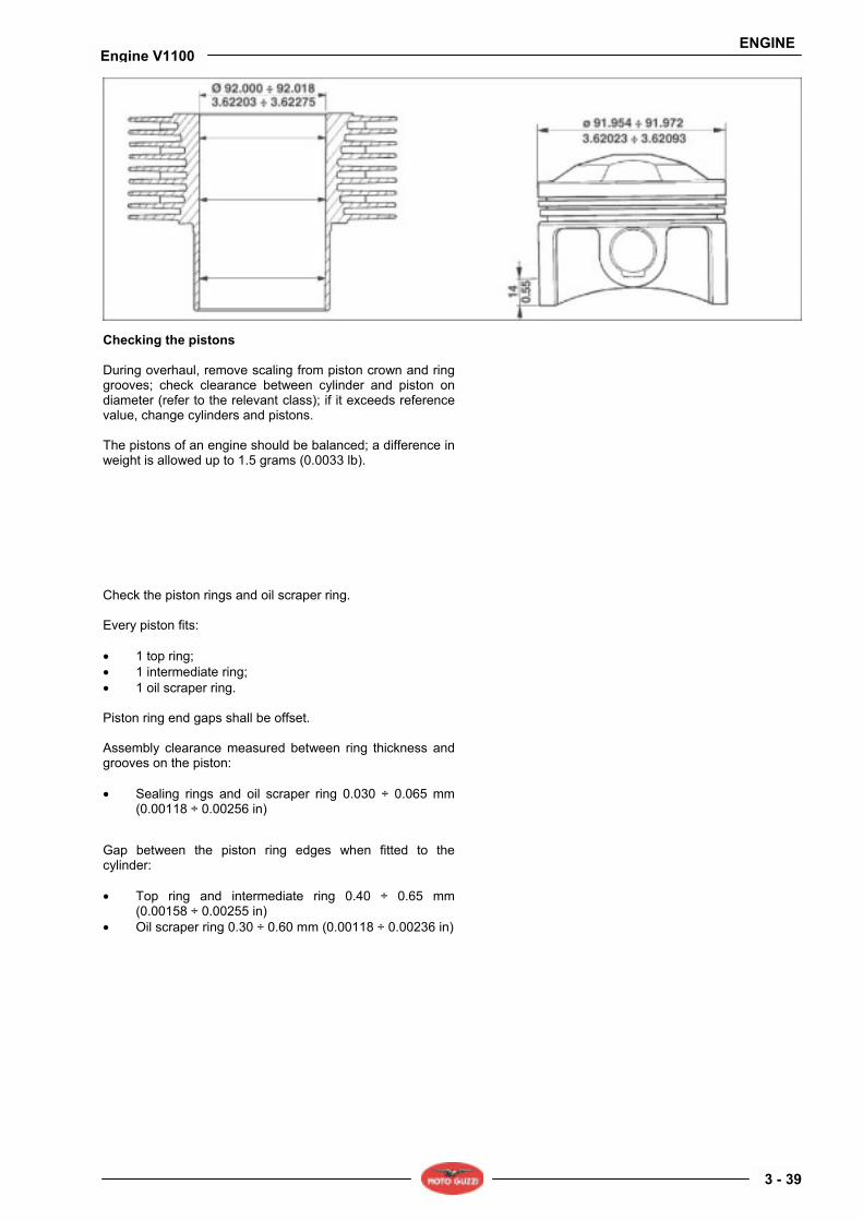
Checking the pistons During overhaul, remove scaling from piston crown and ring grooves; check clearance between cylinder and piston on diameter (refer to the relevant class); if it exceeds reference value, change cylinders and pistons. The pistons of an engine should be balanced; a difference in weight is allowed up to 1.5 grams (0.0033 lb).
Check the piston rings and oil scraper ring. Every piston fits: • 1 top ring; • 1 intermediate ring; • 1 oil scraper ring. Piston ring end gaps shall be offset. Assembly clearance measured between ring thickness and grooves on the piston: • Sealing rings and oil scraper ring 0.030 ÷ 0.065 mm
(0.00118 ÷ 0.00256 in)
Gap between the piston ring edges when fitted to the cylinder: • Top ring and intermediate ring 0.40 ÷ 0.65 mm
(0.00158 ÷ 0.00255 in) • Oil scraper ring 0.30 ÷ 0.60 mm (0.00118 ÷ 0.00236 in)

ENGINE
3 - 40
Engine V1100
INSTALLATION
NOTE The following procedure applies to both cylinder heads.
• Fit the piston
NOTE Check piston correct position referring to the reference marks on the piston crown. Never match pistons to cylinders of different classes.
• Fit the gudgeon pin.
• Fit gudgeon pin circlip.
• Remove the rag used to avoid that foreign matter enters the crankcase.
• Turn the piston rings so as the end gaps are at 120 degrees one from the other.
• Lubricate piston and cylinder. • Using the suitable piston ring compression tool (part
no. 05.92.80.30), fit the cylinder.
WARNING During this operation, ensure not to damage the piston.
ENGINE
3 - 41
Engine V1100
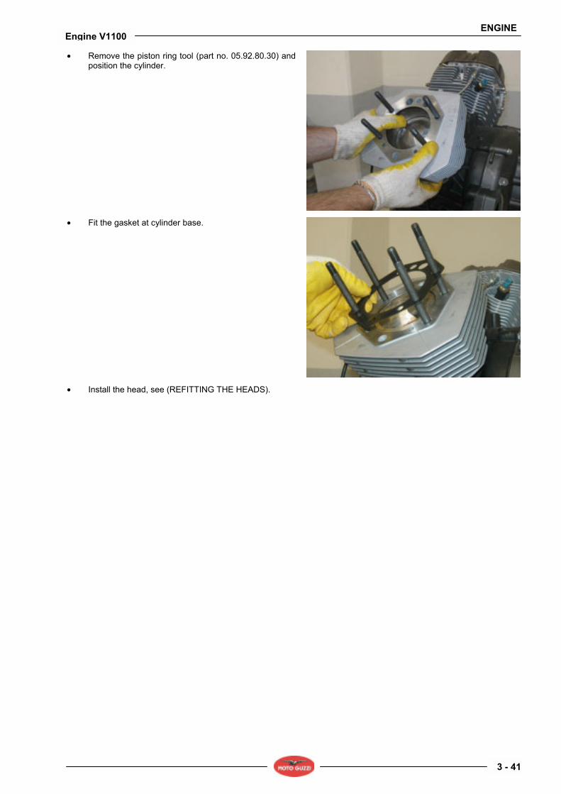
• Remove the piston ring tool (part no. 05.92.80.30) and position the cylinder.
• Fit the gasket at cylinder base.
• Install the head, see (REFITTING THE HEADS).

ENGINE
3 - 42
Engine V1100
3.7. FLYWHEEL 3.7.1. REMOVAL, CHECK AND REASSEMBLY
REMOVAL • Remove the clutch, see (REMOVING THE CLUTCH). • Fit the locking tool (part no. 12.91.18.01) to the
flywheel and loosen the six flywheel screws; work in a cross pattern and in steps.
• Remove the flywheel.
CHECK • Ensure that the flywheel mating surface is not
scratched. • Check that surface mating with crankshaft is not
deformed; if it is, change the flywheel.

ENGINE
3 - 43
Engine V1100
REASSEMBLY • Perform the removal procedure in reversed order.
NOTE Respect flywheel position reference marks.
WARNING Renew the screws upon reassembly since they undergo important stress and load.

ENGINE
3 - 44
Engine V1100
3.8. CRANKSHAFT AND CONNECTING RODS 3.8.1. REMOVAL
• Remove the heads, see (REMOVING THE HEADS). • Remove the cylinders and pistons, see (REMOVAL,
CHECK AND INSTALLATION). • Remove the clutch, see (REMOVING THE CLUTCH). • Remove the flywheel, see (REMOVAL, CHECK AND
REASSEMBLY). • Remove the timing system, see (REMOVING AND
REFITTING). • Remove the oil sump, see (REMOVAL, CHECK AND
REASSEMBLY) • From inside the crankcase, loosen the jointing bolts (A)
and remove the connecting rods (B).
• Loosen and remove the six screws and collect the washers.
• Remove crankshaft flange on generator side.
• Loosen and remove the eight screws and collect the washers.

ENGINE
3 - 45
Engine V1100
• Using the suitable special tool (part no. 12.91.36.00), remove the crankshaft flange.
• Remove the seal, if necessary.
• Slide the crankshaft from the back.

ENGINE
3 - 46
Engine V1100
3.8.2. CHECK
WARNING During this operation flammable vapours are generated and metal particles might be ejected at high speed, it is therefore recommended to avoid bare flames or sparks in the work place; the operator should wear suitable goggles.
CONNECTING RODS When overhauling the connecting rods, the following checks shall be performed: • Bushes condition and clearance between bushes and
gudgeon pins; • Axes parallelism; • Con-rod bearings. The bearings are of the thin shell type, with antifriction alloy preventing settling; change them in case you notice jamming or wear marks.
When changing the bearings, it might be necessary to grind the crank pin. Before grinding the crank pin it is recommended to measure its diameter in the more worn area, as shown in the figure, in order to calculate bearing undersize class and to set crank pin final diameter (after grinding). Checking axes parallelism. Check con-rod straightness before refitting them. This means that you should check that con-rod big end and small end bores are parallel and coplanar. Maximum parallelism and alignment error of the two axes of con-rod big and small end measured at a distance of 200 mm (7.873 inch) is ± 0.10 mm (0.00393 inch).

ENGINE
3 - 47
Engine V1100
Con-rod bearings thickness Bearings for crank pin ø undersized by mm (inch) STANDARD BEARING
(PRODUCTION) mm (inch) 0.254 (0.00999) 0.508 (0.01999) 0.762 (0.02999)
1.662 (0.06543) 1.789 (0.07043) 1.916 (0.07543) From 1.535 (0.06043) to 1.544 (0.06079)
1.671 (0.06578) 0.798 (0.07079) 1.925 (0.07579) Crank pin diameter (B): mm (inch)
Standard ø Undersized by mm (inch) 0.254 (0.00999)
Undersized by mm (inch) 0.508 (0.01999)
Undersized by mm (inch) 0.672 (0.02645)
44.008 ÷ 44.020 mm (1.73259 ÷ 1.73307 in).
43.754 ÷ 43.766 mm (1.72259 ÷ 1.72307 in).
43.500 ÷ 43.512 mm (1.71259 ÷ 1.71307 in).
43.264 ÷ 43.258 mm (1.70330 ÷ 1.70307 in).
Gudgeon pin-to-bush coupling Inner Ø of the bush fitted and
machined mm (inch) gudgeon pin Ø mm (inch) Gudgeon pin-to-bush clearance mm (inch)
22.007 (0.86641) 22.020 (0.86692)
21.994 (0.86590) 21.998 (0.86606) 0.009÷0.026 (0.000354÷0.001024)
Connecting rod weight table
Con-rod total weight g (lb)
Weight of small end side (rotating)
g (lb)
Weight of big end side (rotating)
g (lb)
Colour of weight selection class
642 ± 2.5 (1.4153 ± 0.0055) 476 ± 3.5 (1.0494 ± 0.0077) White
647 ± 2.5 (1.4263 ± 0.0055 479.5 ± 3.5 (1.0571 ± 0.0077) Light blue
652 ± 2.5 (1.4374 ± 0.0055)
165 ± 1 (0.3638 ± 0.0022)
483 ± 3.5 (1.0648 ± 0.0077) orange
Crank pin diameter on flywheel side (C) UNDERSIZED BY mm (inch)
STANDARD PRODUCTION mm (inch) 0.2 (0.0078) 0.4 (0.0157) 0.6 (0.0236)
53.770 (2.11692) 53.570 (2.10905) 53.370 (2.10118) 52.970 (2.08542) 53.951 (2.12405) 53.751 (2.11617) 53.551 (2.10830) 53.351 (2.10042)
Journal diameter on timing side (A)
UNDERSIZED BY mm (inch) STANDARD PRODUCTION mm (inch)
0.2 (0.0078) 0.4 (0.0157) 0.6 (0.0236)
37.775 (1.48720) 37.575 (1.47932) 37.375 (1.47145) 37.975 (1.49507) 37.959 (1.49444) 37.759 (1.48657) 37.559 (1.47869) 37.359 (1.47082)
CRANKSHAFT Inspect the journal surfaces; grind them if they are scratched or oval (refer to undersize tables) and change the complete flanges with main bearings. Undersize values are: 0.2-0.4-0.6 mm (0.0078 0.0157 - 0.0236 inch) Assembly clearance values are: • Between bearing and journal on timing side 0.028 ÷
0.060 mm (0.00110 ÷ 0.00236 in); • Between bearing and journal on flywheel side 0.040 ÷
0.075 mm (0.00157 ÷ 0.00295 inch); • Between bearing and crank pin 0.022 ÷ 0.064 mm
(0.00087 ÷ 0.00252 inch);

ENGINE
3 - 48
Engine V1100
WARNING When grinding the crankshaft pins/journals refer to the shoulder radius value that is: 2.0 ÷ 2.5 mm (0.079 ÷ 0.984 in) for the crank pin, 3.0 ÷ 3.2 mm (0.118 ÷ 1.260 in) for the journal on flywheel side, 1.5 ÷ 1.8 mm (0.059 ÷ 0.071 in) for the journal on timing side.
CHECKING THE WEIGHT FOR CRANKSHAFT BALANCING The connecting rods with bolts fitted, shall be balanced in weight. Allowed difference is 4 grams (0.0088 lb). Apply a weight of 1850 grams (4.0785 lb) to the crankpin to statically balance the crankshaft.

ENGINE
3 - 49
Engine V1100
3.8.3. REASSEMBLY
CONNECTING RODS Perform removal instructions in reverse order, consider the following warnings: • Renew the screws upon reassembly since they
undergo important stress and load. • Assembly clearance between bearing and crank pin is
minimum 0.022 mm (0.00087 inch), maximum 0.064 mm (0.00251 inch).
• Clearance between connecting rod shims and crankshaft shims is 0.30 mm (0.01181 inch) ÷ 0.50 mm (0.01968 inch).
• Tighten the bolts on the caps with a torque wrench to the specified tightening torque.
CRANKSHAFT • Correctly set the crankshaft support flanges
considering their assembly position (indicated by the holes).
• Apply some teflon tape on the two lower rear screws to avoid oil leaks.
• Using the suitable seal tool (part no. 19.92.71.00), install the seal to the flywheel-side flange.
• Hold the camshaft with the suitable tool (part no. 14.92.73.00), and install the flange with seal.
• To complete reassembly, follow the removal procedure in reverse order.

ENGINE
3 - 50
Engine V1100
3.9. OIL SUMP 3.9.1. REMOVAL, CHECK AND REASSEMBLY
REMOVAL
NOTE To remove the oil sump it is necessary to set a suitable collector under the sump to collect used oil and drain all oil from the sump.
• If necessary, remove the filter with the suitable special tool (part no. 01.92.91.00).
• Loosen and remove oil level plug and collect the O-ring.
• Loosen and remove the fourteen screws securing the oil sump to the crankcase.

ENGINE
3 - 51
Engine V1100
• Loosen and remove the four screws and remove the black oil sump.
• Release and remove the two screws.
• Release and remove the two screws. • Remove the mesh filter and collect the gasket.
• Remove the black flange and collect the seal.

ENGINE
3 - 52
Engine V1100
• Once these parts are removed, it is possible to gain access to the oil pressure control valve and the thermostatic valve. Remove them, if necessary.
CHECK • Check that the mesh filter is not dirty; wash and blow
with compressed air, if necessary.
REASSEMBLY • On assembly, perform removal operations in reverse
order, remember to change the gasket.

GEARBOX
4 - 1
Engine V1100
GEARBOX 4
GEARBOX
4 - 2
Engine V1100
SUMMARY 4.1. GEARBOX ........................................................................................................................................................ 3
4.1.1. DIAGRAM.................................................................................................................................................. 3 4.1.2. OPENING THE GEARBOX ....................................................................................................................... 5 4.1.3. DISASSEMBLING THE PRIMARY SHAFT ............................................................................................. 12 4.1.4. DISASSEMBLING THE SECONDARY SHAFT ....................................................................................... 14 4.1.5. DISASSEMBLING THE CLUTCH SHAFT ............................................................................................... 17 4.1.6. CHECK .................................................................................................................................................... 18 4.1.7. REASSEMBLY ........................................................................................................................................ 20
4.2. CLUTCH ......................................................................................................................................................... 21 4.2.1. REMOVING THE CLUTCH...................................................................................................................... 21 4.2.2. CHECKING THE COMPONENTS ........................................................................................................... 24 4.2.3. REFITTING THE CLUTCH ...................................................................................................................... 25

GEARBOX
4 - 3
Engine V1100
4.1. GEARBOX 4.1.1. DIAGRAM
GEARBOX
4 - 4
Engine V1100
Key: 1. Ball bearing 2. Circlip 3. Shim 4. Peg 5. Complete Desmodromic 6. Ball bearing 7. Spring 8. Spacer 9. Circlip 10. Fifth wheel 11. Pin 12. Gear 13. Circlip 14. Washer 15. Roller cage 16. Gear 17. Seal 18. Ball bearing 19. Gear 20. Circlip 21. Retainer 22. Split ring 23. Oil plug 24. Washer 25. Gearbox 26. Aluminium gasket 27. Breather plug 28. Neutral sensor 29. Gasket 30. Seal 31. Bush 32. Gasket 33. Oil drain plug 34. Roller bearing 35. Circlip 36. Belleville washer 37. Spring pusher
38. Shaped washer 39. Sleeve 40. Circlip 41. Idler gear 42. Ball bearing 43. Gear 44. Gear 45. Roller cage 46. Washer 47. Circlip 48. Gear 49. Circlip 50. Gear 51. Primary shaft 52. Transmission gear 53. Ring nut 54. Washer 55. Clutch inner body 56. Seal 57. Ball bearing 58. O-ring 59. Clutch shaft 60. Fork 61. Fork pin 62. Fork 63. Fork 64. Gear 65. Gear 66. Ball bearing 67. Secondary shaft 68. Gear 69. Spacer 70. Spring 71. Index lever 72. Bush 73. Complete preselector 74. Spring

GEARBOX
4 - 5
Engine V1100
4.1.2. OPENING THE GEARBOX
• Remove the starter motor, see (REMOVING THE STARTER MOTOR).
• Ensure that gearbox is in neutral. • Loosen and remove the screw and remove the gear
shift lever.
• Loosen and remove the plug.
• Set a suitably sized container under it, loosen and remove the plug; drain all oil from gearbox, as described in the reference chassis manual, see (REFERENCE MANUALS).
• Release and remove the three screws.

GEARBOX
4 - 6
Engine V1100
• Release and remove the two screws.
• Unscrew and remove the screw.
• Remove the gearbox.
• Set the gearbox on the suitable gearbox support (part no. 14.92.96.00) and in a vice.

GEARBOX
4 - 7
Engine V1100
• Loosen and slide out the odometer fitment and collect the stop washer that stays inside the gearbox.
• Slide out the cylinder and collect the O-ring and the washer.
• Remove the thrust bearing and cap.
• Slide out the two bushes (1) and remove the rod (2); collect bush (3).

GEARBOX
4 - 8
Engine V1100
• Bend washer ends.
• Using the suitable pin wrench (part no. 05.91.26.30) and clutch locking tool (part no. 30.91.28.10), loosen and remove the ring nut; collect the inner clutch body.
• Using the suitable tool (part no. 05.91.25.30) open the gearbox.

GEARBOX
4 - 9
Engine V1100
• Open the gearbox, see (OPENING THE GEARBOX). • Release the spring.
• Press on the selector to help removal of the complete transmission lever.
• Loosen and remove the reference threaded pin.
• Use elastic bands to tie the gearbox shafts and remove the unit.

GEARBOX
4 - 10
Engine V1100
• Remove the bearings from the gearbox.
• Set the gearbox shafts on a bench and remove the elastic bands, paying attention not to damage the unit.
• Separate the shafts and mark the forks before removal.
• Slide out the forks and collect the shaft.

GEARBOX
4 - 11
Engine V1100
• If necessary, change the bearings and remove the clutch shaft.

GEARBOX
4 - 12
Engine V1100
4.1.3. DISASSEMBLING THE PRIMARY SHAFT
• Open the gearbox, see (OPENING THE GEARBOX). • Work on the primary shaft from the side of the second
speed gear.
• Remove the second speed gear, collect the roller cage.
• Remove the sixth speed gear and collect the washer.
• Remove the circlip.

GEARBOX
4 - 13
Engine V1100
• Remove the third and fourth speed gear.
• Remove the circlip and collect the washer.
• Remove the fifth speed gear and collect the roller cage.
• Using a suitable heater, heat up the shaft and remove the transmission helical gear.

GEARBOX
4 - 14
Engine V1100
4.1.4. DISASSEMBLING THE SECONDARY SHAFT
• Open the gearbox, see (OPENING THE GEARBOX). • Work on the secondary shaft from the splined side.
• Remove the washer.
• Remove the second speed gear and collect the roller cage and the washer.
• Remove the circlip.

GEARBOX
4 - 15
Engine V1100
• Remove the sixth speed gear.
• Remove the circlip and collect the washer.
• Remove the fourth speed gear and collect the roller cage.
• Remove the third speed gear and collect the roller cage and the washer.

GEARBOX
4 - 16
Engine V1100
• Remove the circlip.
• Remove the fifth speed gear.
• Remove the circlip, the washer and slide out the first speed gear; collect the roller cage.
• If necessary, remove the bearing.

GEARBOX
4 - 17
Engine V1100
4.1.5. DISASSEMBLING THE CLUTCH SHAFT
• Open the gearbox, see (OPENING THE GEARBOX). • If necessary, working on engine side, remove the cover
seal (1) and bearing (2); collect the O-ring (3).
• Working on gearbox side, remove the circlip (13) and the two split rings (12); collect the roller bearing (14).
• Remove retainer (11). • Carefully remove the Belleville washer (10). • Remove the spring pusher (9) and collect the shaped
washer (8). • Remove coupling (7). • Remove the circlip (6). • Remove the idler gear (5). • Collect the clutch shaft (4).

GEARBOX
4 - 18
Engine V1100
4.1.6. CHECK
CHECKING THE GEAR SHIFT FORKS
NOTE The following procedure applies to all gear shift forks.
Check the fork cam roller (1) and fork teeth (2) for damages, deformation and wear. Change the fork if needed.
Check fork movement; change the forks if movement is irregular.
CHECKING THE DESMODROMIC UNIT Check gear change drum for damages, scratches and wear marks and possibly change the desmodromic. Check desmodromic end (3) for damages and wear marks and possibly change it. Check desmodromic bearing (4) for damages and stains; change the desmodromic if needed.
GEARBOX
4 - 19
Engine V1100
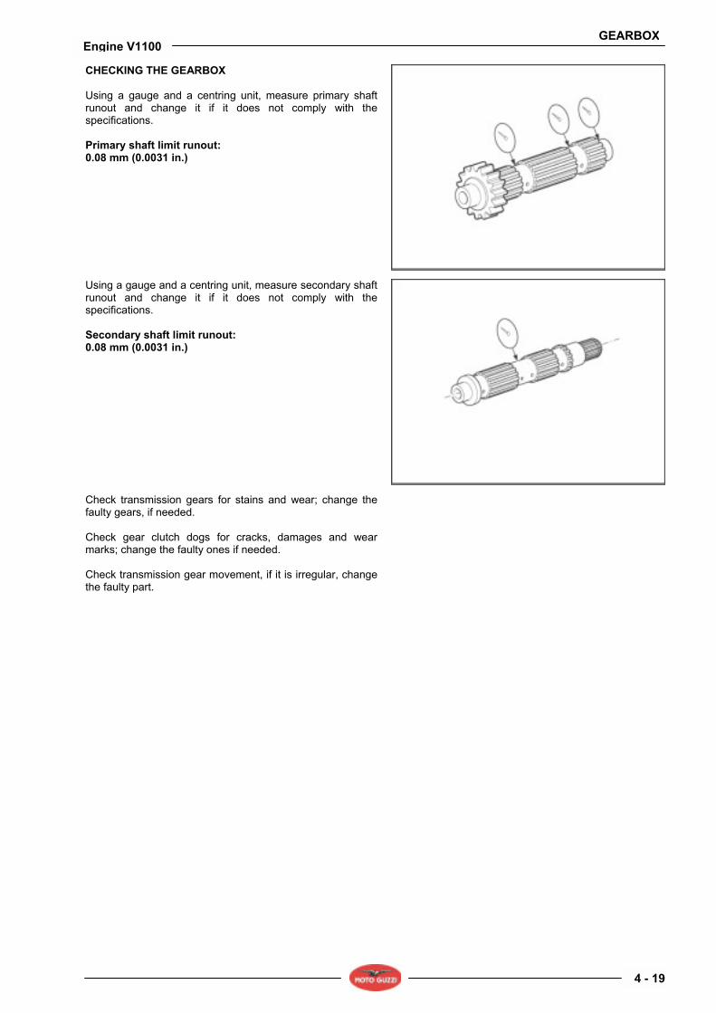
CHECKING THE GEARBOX Using a gauge and a centring unit, measure primary shaft runout and change it if it does not comply with the specifications. Primary shaft limit runout: 0.08 mm (0.0031 in.)
Using a gauge and a centring unit, measure secondary shaft runout and change it if it does not comply with the specifications. Secondary shaft limit runout: 0.08 mm (0.0031 in.)
Check transmission gears for stains and wear; change the faulty gears, if needed. Check gear clutch dogs for cracks, damages and wear marks; change the faulty ones if needed. Check transmission gear movement, if it is irregular, change the faulty part.
GEARBOX
4 - 20
Engine V1100
4.1.7. REASSEMBLY
NOTE For reassembling the clutch shaft, the secondary shaft, the primary shaft and for closing the gearbox, follow the removal instructions in reverse order. Remember to change all seals, circlips and snap rings removed.

GEARBOX
4 - 21
Engine V1100
4.2. CLUTCH 4.2.1. REMOVING THE CLUTCH
• Remove the gearbox unit, see (REMOVING THE GEARBOX).
• Fit locking tool (part no. 12.91.18.01) to the flywheel and tool (part no. 30.90.65.10) to compress clutch springs.
• Loosen and remove the eight screws securing the flywheel gear wheel.
• Remove the gear wheel.
GEARBOX
4 - 22
Engine V1100
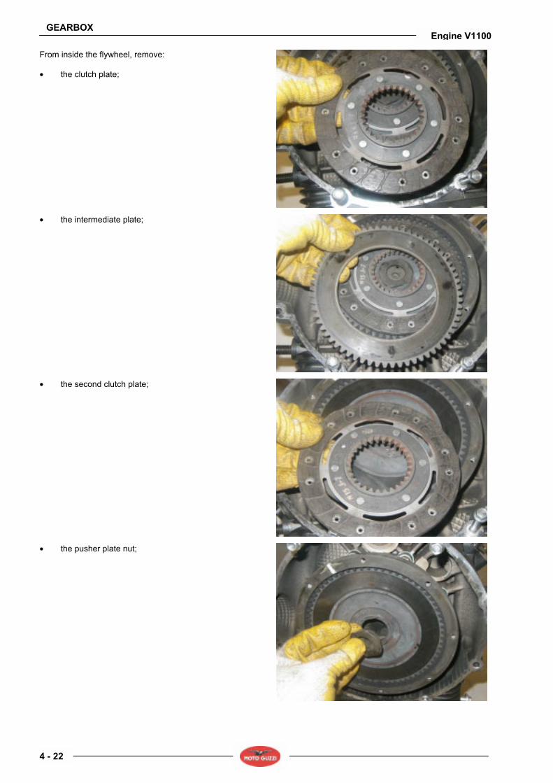
From inside the flywheel, remove: • the clutch plate;
• the intermediate plate;
• the second clutch plate;
• the pusher plate nut;
GEARBOX
4 - 23
Engine V1100
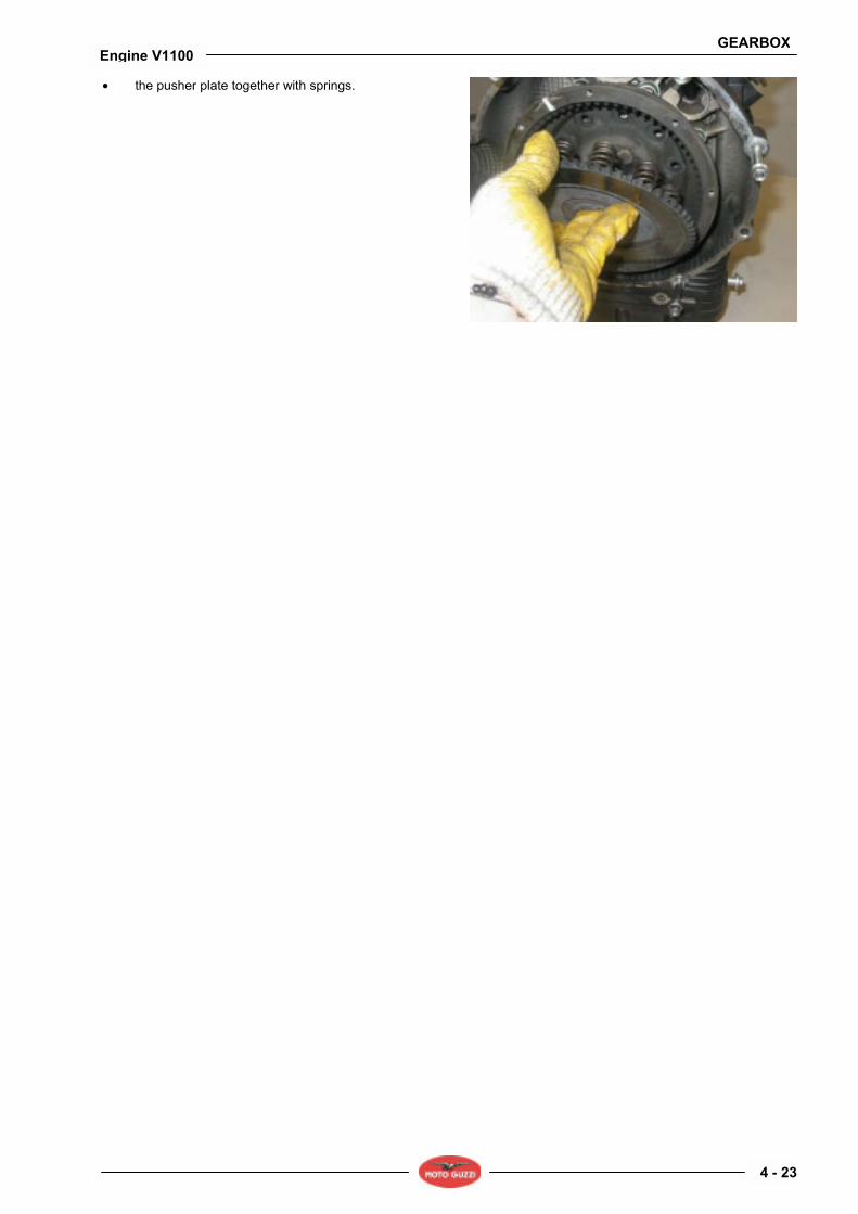
• the pusher plate together with springs.

GEARBOX
4 - 24
Engine V1100
4.2.2. CHECKING THE COMPONENTS
Clutch springs Check that the springs are not yielded or deformed: • Springs compressed to 22 mm (0.8661 inch) should
give a load of 11.25 ÷ 11.70 Kg. (24.80 ÷ 25.79 lb); • Springs compressed to 20 mm (0.7874 inch) should
have a load of 14.75 ÷ 15.30 Kg. (32.52 ÷ 33.73 lb); Spring pusher plate Check that the plate is not worn at the hole where the retainer works, and that the surface mating with driven plate is perfectly flat. Check that toothing inside the flywheel is in good condition.
Driven plates Check that the surfaces mating with the driven plates are perfectly smooth and flat and that external teeth working inside the flywheel are not damaged; change the plate, if needed. Starter gear wheel Check that the surface mating with the driven plate is perfectly smooth and flat. Also check toothing where starter motor sprocket works, ensure it is not damaged or worn; change the gear if necessary.
Clutch inner body Check that teeth are not worn in the areas contacting with the plates.

GEARBOX
4 - 25
Engine V1100
4.2.3. REFITTING THE CLUTCH
Fit the following parts in the flywheel as follows: • the spring pusher plate together with springs.
• Ensure that the reference mark on the pusher plate tooth matches the flywheel reference mark.
• Fit the locking tool (part no. 12.91.18.01) to flywheel and tool (part no. 30.90.65.10) compressing the clutch springs.

GEARBOX
4 - 26
Engine V1100
• Remove the locking tool (part no. 12.91.18.01)
• Fit the clutch plate.
• Fit the intermediate metal plate.
• Fit the clutch plate.

GEARBOX
4 - 27
Engine V1100
• Position the gear wheel aligning the reference mark to the flywheel one.
• Tighten the eight screws securing the gear wheel to the flywheel to the specified torque; proceed in a cross pattern.
• Remove tool (part no. 30.90.65.10) compressing the clutch springs.
• Fit the spring cap. • Install the gearbox.

GEARBOX
4 - 28
Engine V1100

Moto Guzzi S.p.a.Via E.V. Parodi, 5723826 Mandello del Lario (LECCO) ItalyTel. +39 0341 709111Fax +39 0341 709220www.motoguzzi.itwww.servicemotoguzzi.com