Workshop What If
9
WS2-1 ANSYS, Inc. Proprietary © 2009 ANSYS, Inc. All rights reserved. May 28, 2009 Inventory #002670 Workshop What If DesignXploration
-
Upload
charity-stanton -
Category
Documents
-
view
25 -
download
0
description
Workshop What If. DesignXploration. Workshop – what if. Goal Using Parameter Manager to investigate the behavior of stress, mass, and deformation in the hitch receiver shown here as geometry parameters are changed during vertical loading. Model Description - PowerPoint PPT Presentation
Transcript of Workshop What If

WS2-1ANSYS, Inc. Proprietary© 2009 ANSYS, Inc. All rights reserved.
May 28, 2009Inventory #002670
Workshop
What If
DesignXploration

WS2-2ANSYS, Inc. Proprietary© 2009 ANSYS, Inc. All rights reserved.
May 28, 2009Inventory #002670
Training ManualWorkshop – what if
• Goal– Using Parameter Manager to investigate the
behavior of stress, mass, and deformation in the hitch receiver shown here as geometry parameters are changed during vertical loading.
• Model Description– Model is composed of a multibody part (3 bodies)
created in Design Modeler. Constraints and load are shown on the picture on right.
Output parameters
Mass
Max deformation
Max equivalent stress
Input parameters defined in DM
Thk_ds = 2.5 mm
Horiz_ds = 30 mm
Vert_ds = 30 mm
Thk_ds
Horiz_ds
Vert_ds

WS2-3ANSYS, Inc. Proprietary© 2009 ANSYS, Inc. All rights reserved.
May 28, 2009Inventory #002670
Training Manual
2. Double click on Parameter set, we will not go to Mechanical application
Workshop – what if
1. File>Import>Reciver.dsdb
1
2

WS2-4ANSYS, Inc. Proprietary© 2009 ANSYS, Inc. All rights reserved.
May 28, 2009Inventory #002670
Training Manual
3. Add additional three design points in the table of design points
4. Update all Design Points
5. Show status bar
Workshop – what if
3
4
5

WS2-5ANSYS, Inc. Proprietary© 2009 ANSYS, Inc. All rights reserved.
May 28, 2009Inventory #002670
Training Manual
Table of all design points - results
6. Charts, Properties, Tables may not be available by default, go to Main menu>View>Outline
Workshop – what if
6

WS2-6ANSYS, Inc. Proprietary© 2009 ANSYS, Inc. All rights reserved.
May 28, 2009Inventory #002670
Training Manual
7. Highlight parameter P2 in the Outline of all parameters
8. Double click on Design Point vs P2 to obtain a Chart
Workshop – what if
7
8

WS2-7ANSYS, Inc. Proprietary© 2009 ANSYS, Inc. All rights reserved.
May 28, 2009Inventory #002670
Training Manual
9. Double click on Parameters Parallel Chart (all)
Each color coded line on the plot represents one of the design points. Individual parameters are displayed along the bottom of the chart
Top and bottom values on the chart indicate the range relative to each parameter
Workshop – what if
9
9
WS2-8ANSYS, Inc. Proprietary© 2009 ANSYS, Inc. All rights reserved.
May 28, 2009Inventory #002670
Training Manual
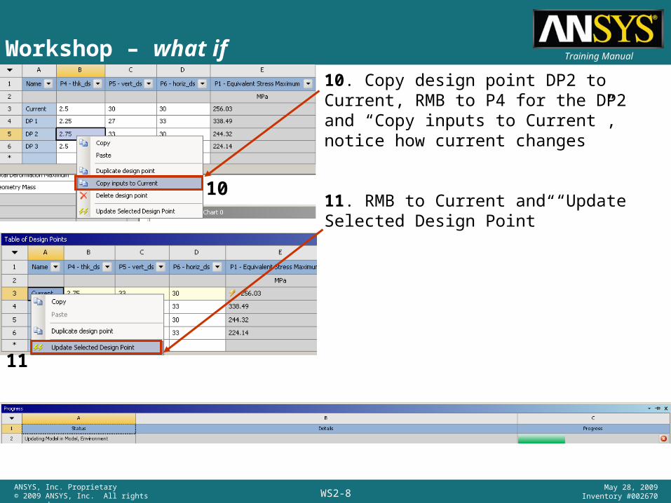
10. Copy design point DP2 to Current, RMB to P4 for the DP2 and “Copy inputs to Current”, notice how current changes
11. RMB to Current and “Update Selected Design Point”
Workshop – what if
10
11
WS2-9ANSYS, Inc. Proprietary© 2009 ANSYS, Inc. All rights reserved.
May 28, 2009Inventory #002670
Training Manual
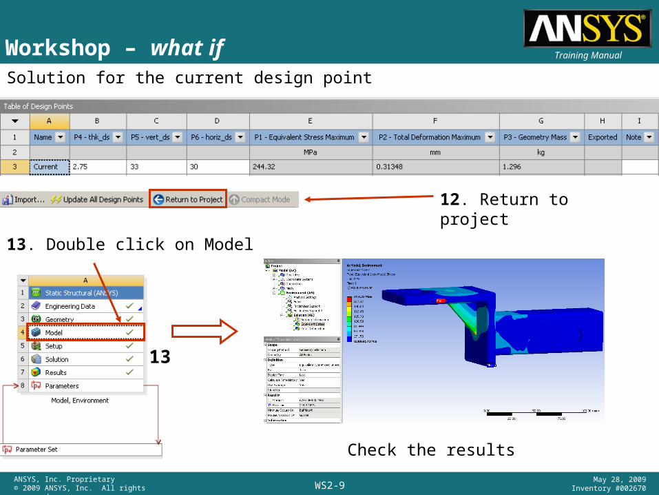
12. Return to project
13. Double click on Model
Check the results
Solution for the current design point
Workshop – what if
13