Workshop Preprint
37
Workshop Preprints CSE 2016 Workshop on Continuous Software Engineering co-located with SE 2016 Vienna, February 23rd, 2016 Editors: Horst Lichter, RWTH Aachen University Bernd Brügge, TU München Dirk Riehle, FAU Nürnberg Lukas Alperowitz, TU München Andreas Steffens, RWTH Aachen University
-
Upload
truongminh -
Category
Documents
-
view
253 -
download
1
Transcript of Workshop Preprint
Workshop Preprints
CSE 2016
Workshop on Continuous Software Engineering
co-located with SE 2016Vienna, February 23rd, 2016
Editors:Horst Lichter, RWTH Aachen UniversityBernd Brügge, TU MünchenDirk Riehle, FAU NürnbergLukas Alperowitz, TU MünchenAndreas Steffens, RWTH Aachen University
Workshop on Continuous Software Engineering
Horst Lichter1, Bernd Brügge2, Dirk Riehle3
1RWTH Aachen University, Research Group Software Construction [email protected]
2Technische Universität München, Institut für Informatik / I1T [email protected]
3Friedrich-Alexander-University Erlangen-Nürnberg, Open Source Research Group [email protected]
In order to develop and deliver high-quality products to their customers, software companies have to adopt state-of-the-art software development processes. To face this challenge, companies are applying innovative methods, approaches and techniques like agile methods, DevOps, Continuous Delivery, test automation, infrastructure as code or container-based virtualization.
These new approaches have a high impact on the specification, design, development, maintenance, operation and the evolution of software systems. Therefore, common software engineering activities, organizational forms and processes have to be questioned, adapted and extended to ensure continuous and unobstructed software development (Continuous Software Engineering). So far, there is a lack of systematic approaches to face these challenges.
The goal of this workshop is to present and discuss innovative solutions, ideas and experiences in the area of Continuous Software Engineering (CSE).
The workshop aims to cover the following topics:
• DevOps & Release Engineering• Approaches to Continuous Integration/Delivery/Deployment• Infrastructure as Code• Test Automation & Optimization• Monitoring & Performance• Security for DevOps• Provisioning of Software & Infrastructure• Application Virtualization with Container• Engineering of Deployment Pipelines• Quality & Metrics for DevOps
Copyright © 2016 for the individual papers by the papers' authors. Copying permitted for private and academic purposes. This volume is published and copyrighted by its editors.
H. Lichter, B. Brügge, D. Riehle: Workshop on Continuous Software Engineering (CSE)
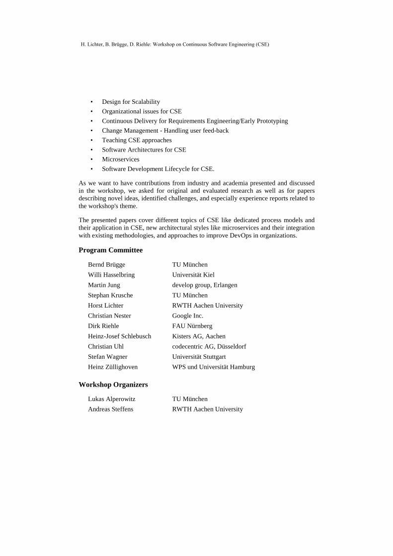
• Design for Scalability • Organizational issues for CSE • Continuous Delivery for Requirements Engineering/Early Prototyping • Change Management - Handling user feed-back • Teaching CSE approaches • Software Architectures for CSE • Microservices • Software Development Lifecycle for CSE.
As we want to have contributions from industry and academia presented and discussed in the workshop, we asked for original and evaluated research as well as for papers describing novel ideas, identified challenges, and especially experience reports related to the workshop's theme.
The presented papers cover different topics of CSE like dedicated process models and their application in CSE, new architectural styles like microservices and their integration with existing methodologies, and approaches to improve DevOps in organizations.
Program Committee
Bernd Brügge TU München Willi Hasselbring Universität Kiel Martin Jung develop group, Erlangen Stephan Krusche TU München Horst Lichter RWTH Aachen University Christian Nester Google Inc. Dirk Riehle FAU Nürnberg Heinz-Josef Schlebusch Kisters AG, Aachen Christian Uhl codecentric AG, Düsseldorf Stefan Wagner Universität Stuttgart Heinz Züllighoven WPS und Universität Hamburg
Workshop Organizers
Lukas Alperowitz TU München Andreas Steffens RWTH Aachen University
H. Lichter, B. Brügge, D. Riehle: Workshop on Continuous Software Engineering (CSE)
Achieving Cloud Scalability with Microservices and
DevOps in the Connected Car Domain
Dr. Tobias Schneider
Connected Car
Elektrobit Automotive GmbH
Am Wolfsmantel 46
91058 Erlangen
Abstract: The connected car business has high demands on the exchange of data and
files between the connected car on the road, and a variety of services in the backend. To
solve current and upcoming challenges in the best way, a scalable and flexible
architecture and team setup is needed. The paper has its background in the automotive IT
industry at Elektrobit (EB) and describes our starting point, challenges and practical
experiences. We have chosen microservices as an architectural paradigm in order to be
able to replicate granular services for scalability, and to easily replace a deprecated
service. For the development and operations of the services, we decided to have one
team which is responsible for the backend infrastructure in the cloud. Also a DevOps
culture was established. This allows us to deploy quickly services with increased
operational efficiency and code quality.
1 Introduction
The Internet of Things poses new challenges on the software industry. This does not
only apply to cars - but apparently connecting cars with backend services are one of the
major topics in this field. The Google Android initiative for cars or the current successes
in automated driving are just a few examples demonstrating this. One major aspect in
connecting things is that there is little value by providing just the connection. The benefit
from being connected always goes hand in hand with the provision of a specific service,
which is generating the benefit from the connection.
In the context of software solutions for connected cars, this means that besides providing
the connectivity for the car itself, and hosting a backend, one major task is to offer the
right services for the right purpose. One example of such a service, could be offering
online navigation. The routing algorithm is implemented by navigation software experts
whereas the data exchange between the car and the backend, and the creation of the
service is performed by connectivity experts.
Copyright © 2016 for the individual papers by the papers' authors. Copying permitted for private and academic purposes. This volume is published and copyrighted by its editors.
T. Schneider: Microservices and DevOps in the Connected Car Domain
2 Requirements on software development for connected car solutions
EB is a supplier for IT solutions in the automotive sector and offers solutions in a wide
variety of areas, such as navigation, vehicle diagnostics and services around the car. As
connectivity became a major topic in the automotive industry, EB founded the connected
car domain in February 2014. The teams in this new domain were already experienced in
agile methods like Scrum [SK04] or Kanban [AD2010] and continuous integration. The
new key technology cloud computing was changing processes and requirements. From a
technical perspective the following key points were identified:
Scalability (T1): Some components are more often used or are more resource
intense than other components. Hence, we need ways to replicate specific
components in an efficient way.
Exchangeability (T2): Any component in a major software solution is outdated
at some point in time. We need a way to exchange a component easily without
affecting other components (loose coupling).
Reuse (T3): Many projects had a similar feature set for software to work with
the cloud. Hence, we identified a set of standard services to be used in multiple
projects.
Continuous deployment (T4): A feature added to a service must be visible at
once, so that the compatibility with other services can be tested automatically.
Code quality (T5): The same code shall be used in different projects (T3).
Hence, the demands on quality and genericity have increased.
From an organizational point of view the following points had the strongest impact:
Working mode (O1): Is the development in a cloud environment compatible
with agile methods, or is another working mode needed?
Team Setup (O2): Have our team members the right skills? Do we need
specialists within the team or specialized teams?
Self-Service (O3): In cloud computing an instance or repository must be
available at once, so no additional tasks in the process are acceptable.
Configuration Management (O4): For every solution in the cloud an
infrastructure is set up which needs to be reproducible for quality and
controlling reasons.
Cost controlling (O5): The scaling in cloud computing comes with new
demands on cost controlling as instances are paid on an hourly basis and
services like AWS Lambda [AC15] are payed per usage.
3 Microservices
The micro-service architecture is defined as developing an application as a set of small
independent services, where each of the services is running in its own independent
process [NS14]. Services communicate with some lightweight mechanisms like HTTP
[FL14] and are deployed absolutely independently [NS14]. For us, the key reason to
T. Schneider: Microservices and DevOps in the Connected Car Domain
decide for an architecture based on microservices was the ability to replicate on demand
across servers [FL14], which targets directly requirement T1. Moreover, an architectural
paradigm with microservices enforces the single responsibility of an individual service
and modularity via loose coupling (T2). From our experience the modularity of the
service is also the key to reuse (T3). The requirements in different projects are most of
the time similar but very seldom exactly the same. Additional requirements and features
can be easily integrated into a microservice or outsourced in another service. When and
how to perform this, is the crucial architectural design decision.
4 DevOps
Cloud computing changes the ways a team cooperates as a team and cooperates with
other teams. The deployment of software is an essential task in every release of a
software component. Features which were formerly provided by the IT department are
now directly part of applications via infrastructure as code [LM12]. This is blurring the
line between traditional software development and operations. There are different setups
to target this:
Close collaboration between the operations team and the development team
Developers and operators in one team
Every team member performs operations and develops software
EB has decided to follow the latter approach for teams working primary with
connectivity and backend infrastructure. The reason behind this is that cloud computing
and connecting things are the key expertise of the employees working on connectivity
solutions. In this context every software developer needs to be familiar with these
techniques (O2) and needs knowledge in performing operations. In bigger projects
several teams are working together. In this case, one team takes over the DevOps part.
The cooperating teams concentrate purely on software development. Microservice
architecture in this context means that every service has a single responsibility although
the algorithm behind the service might be more complicated (e.g. a routing algorithm).
Regarding the working mode (O1) we have decided to follow a Kanban approach. Tasks
in operations often need to be performed at once when they are occurring (e.g. the
outage of a server). In Scrum, activities need to be planned. This is not possible with this
kind of tasks. Kanban opens the possibilities to work immediately on high priority
targets and to include feature development. Every DevOps team has the rights to start
and stop instances and services in their respective stage which allows controlled self-
services on cloud resources (O3+O5).
With this setup the next step is to setup a continuous deployment process (T4). In this
case automation is the key for quality and efficiency with techniques like infrastructure
as code [LM12] being the key factors. We are successfully working with AWS
CloudFormation [DP15] to have our infrastructure as code which makes the
configuration reproducible (O4). Code can be deployed directly to test instances from
the build server (T4). Only the release needs manual interaction.
T. Schneider: Microservices and DevOps in the Connected Car Domain
5 Software reuse with inner source
One key decision to enable software reuse (T3) is the adaption of open source techniques
into our development processes. We followed here the inner source (IS) approach
[CR15] by establishing a software forge where the source code was made available to all
developers. A forge is a central place where a well-documented code base is kept forever
with the possibility to search [CR15]. This allows the usage of the code and the review
of the code by all developers. Following Linus´s law “Given enough eyeballs, all bugs
are shallow” [RE01] we can achieve a higher code quality (T5) then with the common
four-eye principle alone. Our experiences showed that the code quality improved and
that teams were starting to work together, especially on common tooling. A set of
microservices is available via the forge enabling software reuse in other projects and
improving the overall development time.
6 Summary
With our current setup EB has adopted to change and new environments by changing the
culture in software development from a classic agile setup to a DevOps culture. This
enables EB to cope with the new technical challenges of cloud computing. From an
architectural perspective, the decision for microservices enables us to scale our services,
and gives us the necessary flexibility. This is supported from an organizational
perspective with a DevOps culture embedded in an agile mind-set and the quality
improvements and the possibility of software reuse from the inner source approach.
Literature
[AC15] Astakhov V., Chayel M.: Lambda Architecture for Batch and Real-Time Processing on
AWS with Spark Streaming and Spark SQL. AWS Whitepaper:
https://d0.awsstatic.com/whitepapers/lambda-architecure-on-for-batch-aws.pdf (retrieved
07.12.2015), 2015
[AD10] Anderson, David J. Kanban. Blue Hole Press, 2010.
[CR15] Capraro M., Riehle D.: Inner Source in Platform-based Product Engineering. Friedrich-
Alexander University Erlangen Nürnberg Technical Report CS-2015-02, 2015
[DP15] Dalbahanian P.: Overview of deployment options on AWS, AWS whitepaper,
https://d0.awsstatic.com/whitepapers/overview-of-deployment-options-on-aws.pdf
(retrieved 07.12.2015), 2015
[FL14] Fowler M., Lewis J.: Microservices a definition of this new architectural term,
http://martinfowler.com/articles/microservices.html (retrieved 07.12.2015), 2014
[LM12] Loukides M.: What is DevOps?, O’Really Media Inc., 2012
[NS14] Namiot, D., Sneps-Sneppe M.: On micro-services architecture. International
Journal of Open Information Technologies 2.9: p- 24-27. 2014 [SK04] Schwaber, Ken. Agile project management with Scrum. Microsoft Press, 2004.
[RE01] Raymond, Eric S. The Cathedral & the Bazaar: Musings on linux and open source by an
accidental revolutionary. " O'Reilly Media, Inc.", 2001.
T. Schneider: Microservices and DevOps in the Connected Car Domain
Model-Integrating Microservices: A Vision Paper
Mahdi DerakhshanmaneshUniversity of Koblenz-Landau
Institute for Software [email protected]
Marvin GriegerUniversity of Paderborn
Department of Computer [email protected]
Abstract: Model-integrating development is a novel approach that aims to provide acomprehensive conceptual framework for the engineering of flexible software systems.The atomic building blocks for architecting model-integrating software are model-integrating components which support the modular cooperation of flexible models andefficient code at runtime. Model-integrating components achieve flexibility by usingmodels at runtime and operations on them like querying, transforming and interpreting.Microservices achieve flexibility by upgrading whole components at runtime. In thisshort paper, we sketch the vision of Model-Integrating Microservices (MIMs) thatcombine the strengths of model-integrating components with microservices to supportcontinuous software engineering. With this early work, we intent to initiate a fruitfuldiscussion about architectural design considerations in the community.
1 Background and Motivation
Model-Integrating Development (MID) [Der15] is a novel approach that aims to pro-vide a comprehensive conceptual framework for the design and development of flexiblesoftware that can be adapted easily and – in parts – even autonomously [ST09]. More-over, being able to make changes quickly and to evolve software easily also supportslongevity [GRG+15]. We observe that these capabilities are similarly useful in the emerg-ing trend of Continuous Software Engineering (CSE).
The building blocks for MID are Model-Integrating Components (MoCos) which we havepresented and implemented in previous research [DEIE14]. MoCos result from the sym-biosis of Component-Based Development (CBD) [SGM02] and Model-Driven Develop-ment (MDD) [BCW12] concepts. A MoCo is a non-redundant, reusable and executablecombination of logically related models and code in an integrated form where both partsare stored together in one component.
In traditional MDD, models (e.g., UML activity models, feature models, component mod-els) are used at design time. In contrast, in MID models are used directly at runtime, too.As a result, the internals of MoCos can be easily monitored and analyzed using modelqueries, as well as systematically modified using repeatable model transformations. Thesame techniques can be used for evolving components using an editor during develop-ment and maintenance, and adapting them at runtime using an administration panel or anautonomic adaptation manager component.
By combining the strengths of modeling languages (e.g., abstraction, separation of con-
Copyright © 2016 for the individual papers by the papers' authors. Copying permitted for private and academic purposes. This volume is published and copyrighted by its editors.
M. Derakhshanmanesh, M. Grieger: Model-Integrating Microservices
cerns) and programming languages (e.g., performance) within components, the MoCoconcept yields flexible and well-performing software.
Being able to evolve software easily and quickly is also a main goal of the current trendof microservices [New15]. Microservices support a fine-grained approach to the modularimplementation of distributed, flexible, fault-tolerant and highly responsive software sys-tems. In contrast to the MoCo approach, which concentrates on the technical means foradaptability of component internals at runtime, the microservice approach concentrates onupgradeability of individual, reasonable-sized software components as a whole.
To summarize, we observe that our ongoing work on MoCos has the potential to fulfillgoals similar or complementary to microservices. In order to understand the opportunitiesand challenges, we sketch an initial vision of a novel software architecture concept thataims to combine the strengths of MoCos with the capabilities of microservices. Thisconcept is introduced subsequently and shall serve as an initial baseline for discussion.
2 Architecture Concept
The architecture concept of Model-Integrating Microservices (MIMs) builds on top ofthe established MoCo concept. An MIM is a MoCo that is realized with microservicetechnology. Therefore, an MIM adds a couple of additional benefits to the MoCo concept.
The benefits of MoCos over other component concepts are: (i) enhanced flexibility be-cause the software system and its individual components can be observed using modelqueries, can be modified by adapting models using an editor or model transformationsand can be executed using model interpreters, (ii) support of separation of concerns be-cause each model targets a concern, (iii) understandability and maintainability becausemodels are assumed to be easier to understand and easier to handle than code, (iv) self-documentation because a well designed modeling language is assumed to be a documen-tation and (v) no synchronization problem because there is no redundancy between modeland code within a MoCo unless it is introduced willfully, e.g., to realize reflection.
The expected added value of MIMs over the MoCo concept are: (i) self-containmentbecause a MIM is deployed together with its full infrastructure and dependencies, (ii) dis-tribution because MIMs communicate over a network and (iii) decentralization w.r.t. databecause each MIM manages its own data; especially including its models.
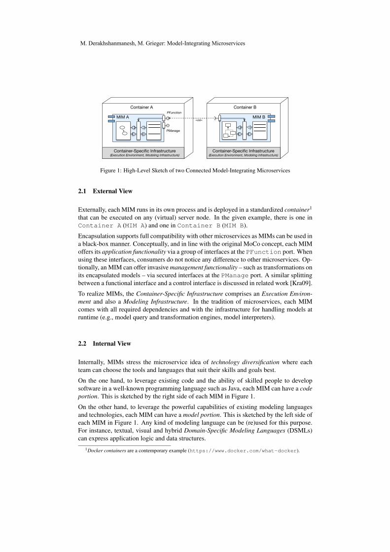
An example of two MIMs is depicted schematically in Figure 1. A description from anexternal point of view and an internal point of view is given subsequently.
M. Derakhshanmanesh, M. Grieger: Model-Integrating Microservices
Container A
MIM A
Container B
«use»MIM B
Container-Specific Infrastructure(Execution Environment, Modeling Infrastructure)
Container-Specific Infrastructure(Execution Environment, Modeling Infrastructure)
PFunction
PManage
Figure 1: High-Level Sketch of two Connected Model-Integrating Microservices
2.1 External View
Externally, each MIM runs in its own process and is deployed in a standardized container1
that can be executed on any (virtual) server node. In the given example, there is one inContainer A (MIM A) and one in Container B (MIM B).
Encapsulation supports full compatibility with other microservices as MIMs can be used ina black-box manner. Conceptually, and in line with the original MoCo concept, each MIMoffers its application functionality via a group of interfaces at the PFunction port. Whenusing these interfaces, consumers do not notice any difference to other microservices. Op-tionally, an MIM can offer invasive management functionality – such as transformations onits encapsulated models – via secured interfaces at the PManage port. A similar splittingbetween a functional interface and a control interface is discussed in related work [Kra09].
To realize MIMs, the Container-Specific Infrastructure comprises an Execution Environ-ment and also a Modeling Infrastructure. In the tradition of microservices, each MIMcomes with all required dependencies and with the infrastructure for handling models atruntime (e.g., model query and transformation engines, model interpreters).
2.2 Internal View
Internally, MIMs stress the microservice idea of technology diversification where eachteam can choose the tools and languages that suit their skills and goals best.
On the one hand, to leverage existing code and the ability of skilled people to developsoftware in a well-known programming language such as Java, each MIM can have a codeportion. This is sketched by the right side of each MIM in Figure 1.
On the other hand, to leverage the powerful capabilities of existing modeling languagesand technologies, each MIM can have a model portion. This is sketched by the left side ofeach MIM in Figure 1. Any kind of modeling language can be (re)used for this purpose.For instance, textual, visual and hybrid Domain-Specific Modeling Languages (DSMLs)can express application logic and data structures.
1Docker containers are a contemporary example (https://www.docker.com/what-docker).
M. Derakhshanmanesh, M. Grieger: Model-Integrating Microservices
Importantly, in contrast to MDD, no code is generated for these designed models. Modelssuch as process descriptions and can be executed by model interpreters that traverse themodel’s abstract syntax graph representation at runtime. In this regard, DSMLs serve asimilar purpose like interpreted scripting languages.
Models are integrated systematically with code inside of an MIM. This approach assumesthat, from a technical point of view, code objects and model objects can both be handledequally, i.e., they can be referenced and their behavior can be invoked by calling methodsof a facade. Objects from the code portion and the model portion can be connected ina hard-coded manner but there are flexible alternatives, too. For example, the mediatorpattern [GHJV95] can be followed as illustrated in Figure 1.
3 Impact and Synergy Effects
Based on experience from our established and ongoing research on MoCos, we are con-vinced that using microservices to realize the MoCo concept in the form of MIMs willenable the engineering of even more flexible software systems. This is due to the factthat the MoCo concept and the microservice concept address complementary concerns toachieve dynamism and to support continuous software engineering.
MoCos focus primarily on the internals of components, i.e., on the use of domain-specificand general-purpose modeling languages and modeling capabilities such as querying,transforming and interpreting for the systematic analysis and adaptation of parts of com-ponents during design and at runtime. Microservices focus primarily on the outside ofcomponents and their containers, i.e., on component size and boundaries, aspects of distri-bution, updatability and rapid (re)deployment.
Next, we describe an excerpt of opportunities and challenges related to the MIM concept.
3.1 Opportunities
In terms of opportunities, the MIM concept brings a couple of advantages over traditionalmicroservices and vice-versa.
Most notably, the MIM approach brings the whole world of modeling and especially mod-els at runtime to the microservice world. This enables the use of various kinds of general-purpose and domain-specific modeling languages, thus supporting all advantages of mod-eling like abstraction and separation of concerns via different views. Central to MIMs isthe added flexibility of using models at runtime, so changes to component internals can bemade systematically without swapping the whole component.
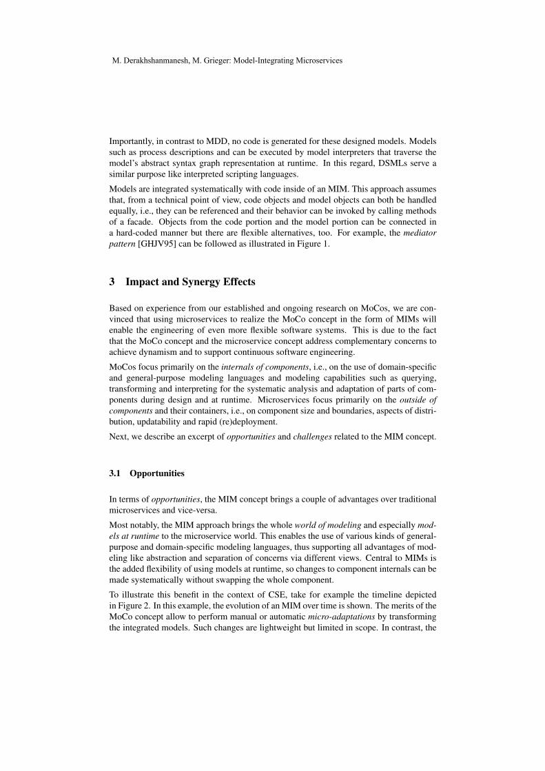
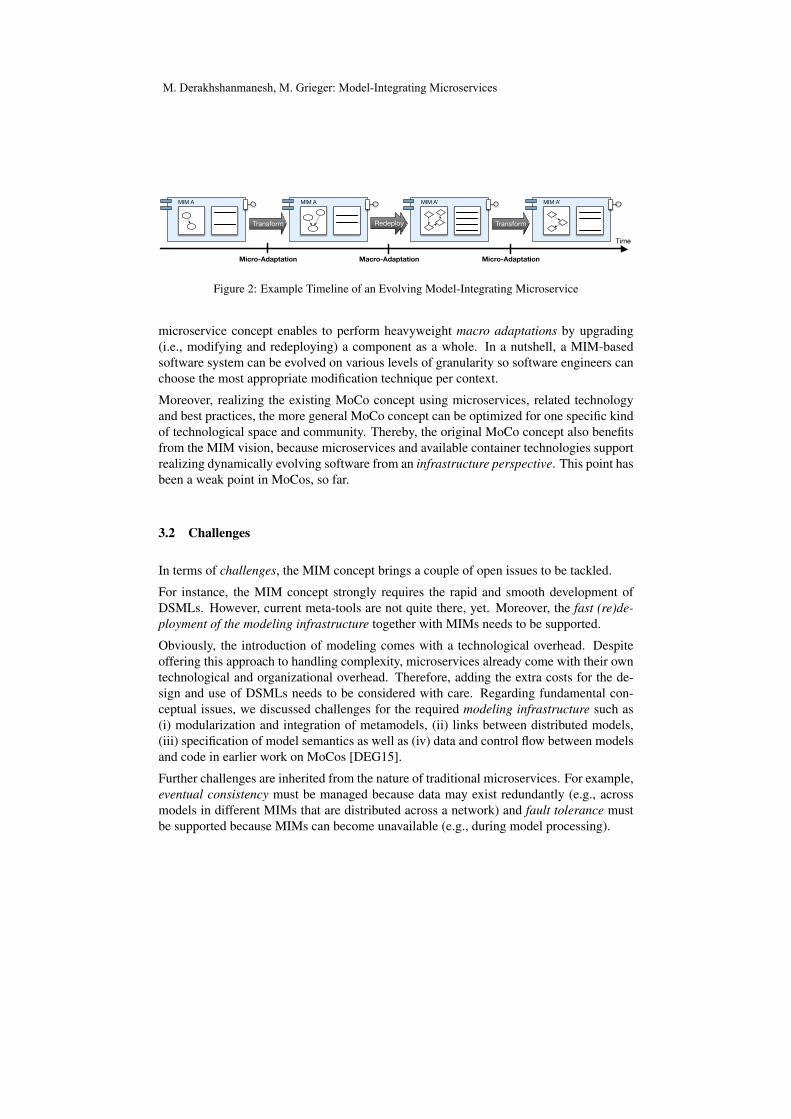
To illustrate this benefit in the context of CSE, take for example the timeline depictedin Figure 2. In this example, the evolution of an MIM over time is shown. The merits of theMoCo concept allow to perform manual or automatic micro-adaptations by transformingthe integrated models. Such changes are lightweight but limited in scope. In contrast, the
M. Derakhshanmanesh, M. Grieger: Model-Integrating Microservices
Transform Transform
MIM A’MIM AMIM A MIM A’
Time
Redeploy
Micro-Adaptation Macro-Adaptation Micro-Adaptation
Figure 2: Example Timeline of an Evolving Model-Integrating Microservice
microservice concept enables to perform heavyweight macro adaptations by upgrading(i.e., modifying and redeploying) a component as a whole. In a nutshell, a MIM-basedsoftware system can be evolved on various levels of granularity so software engineers canchoose the most appropriate modification technique per context.
Moreover, realizing the existing MoCo concept using microservices, related technologyand best practices, the more general MoCo concept can be optimized for one specific kindof technological space and community. Thereby, the original MoCo concept also benefitsfrom the MIM vision, because microservices and available container technologies supportrealizing dynamically evolving software from an infrastructure perspective. This point hasbeen a weak point in MoCos, so far.
3.2 Challenges
In terms of challenges, the MIM concept brings a couple of open issues to be tackled.
For instance, the MIM concept strongly requires the rapid and smooth development ofDSMLs. However, current meta-tools are not quite there, yet. Moreover, the fast (re)de-ployment of the modeling infrastructure together with MIMs needs to be supported.
Obviously, the introduction of modeling comes with a technological overhead. Despiteoffering this approach to handling complexity, microservices already come with their owntechnological and organizational overhead. Therefore, adding the extra costs for the de-sign and use of DSMLs needs to be considered with care. Regarding fundamental con-ceptual issues, we discussed challenges for the required modeling infrastructure such as(i) modularization and integration of metamodels, (ii) links between distributed models,(iii) specification of model semantics as well as (iv) data and control flow between modelsand code in earlier work on MoCos [DEG15].
Further challenges are inherited from the nature of traditional microservices. For example,eventual consistency must be managed because data may exist redundantly (e.g., acrossmodels in different MIMs that are distributed across a network) and fault tolerance mustbe supported because MIMs can become unavailable (e.g., during model processing).
M. Derakhshanmanesh, M. Grieger: Model-Integrating Microservices
4 Concluding Remarks
We believe that the symbiosis of architectural concepts from the worlds of MoCos on theone hand, and microservices on the other hand, opens doors for interesting opportunitiesin continuous software engineering. With MIMs, software engineers can benefit from theflexibility of modeling languages across the full software lifecycle including runtime. Bypresenting this early work, we hope to initiate a discussion on architectural design consid-erations. Moreover, we plan to realize an MIM variant of the MoCo infrastructure [Der15]as a technical basis for carrying out additional feasibility studies.
Acknowledgements. This work is supported by the Deutsche Forschungsgemeinschaft(DFG) under grants EB 119/11-1 and EN 184/6-1. We thank Gregor Engels for pointingus at microservices and we thank Jurgen Ebert for his feedback on the text.
References
[BCW12] Marco Brambilla, Jordi Cabot, and Manuel Wimmer. Model-Driven Software Engineer-ing in Practice. Morgan & Claypool, 2012.
[DEG15] Mahdi Derakhshanmanesh, Jurgen Ebert, and Marvin Grieger. Challenges for Model-Integrating Components. In Proceedings of the 2nd International Workshop on Model-Driven Engineering for Component-Based Software Systems co-located with 18th Inter-national Conference on Model Driven Engineering Languages and Systems (MoDELS2015), Ottawa, Kanada, September 28, 201, 2015.
[DEIE14] Mahdi Derakhshanmanesh, Jurgen Ebert, Thomas Iguchi, and Gregor Engels. Model-Integrating Software Components. In Juergen Dingel and Wolfram Schulte, editors,Model Driven Engineering Languages and Systems, 17th International Conference,MODELS 2014, Valencia, Spain, September 28 - October 3, 2014, Valencia, Spain,2014. Springer.
[Der15] Mahdi Derakhshanmanesh. Model-Integrating Software Components - EngineeringFlexible Software Systems. Springer, 2015.
[GHJV95] Erich Gamma, Richard Helm, Ralph Johnson, and John Vlissides. Design Patterns:Elements of Reusable Object-Oriented Software. Addison-Wesley Longman PublishingCo., Inc., Boston, MA, USA, 1995.
[GRG+15] Ursula Goltz, Ralf H. Reussner, Michael Goedicke, Wilhelm Hasselbring, LukasMartin, and Birgit Vogel-Heuser. Design for future: managed software evolution. Com-puter Science - Research and Development, 30(3-4):321–331, 2015.
[Kra09] Sacha Krakowiak. Component Control. In Middleware Architecture with Patterns andFrameworks (Distributed under a Creative Commons license), chapter 7.4.5. 2009.
[New15] Sam Newmann. Building Microservices. O’Reilly and Associates, 2015.
[SGM02] Clemens Szyperski, Dominik Gruntz, and Stephan Murer. Component Software - Be-yond Object-Oriented Programming. Addison-Wesley, second edition, 2002.
[ST09] Mazeiar Salehie and Ladan Tahvildari. Self-Adaptive Software: Landscape and Re-search Challenges. ACM Trans. Auton. Adapt. Syst., 4(2):14:1–14:42, 2009.
M. Derakhshanmanesh, M. Grieger: Model-Integrating Microservices
Experience Report: A Comparison between Commercial and Open Source Reference Implementations for the
Rugby Process Model
Sajjad Taheritanjani, Stephan Krusche, Bernd Bruegge
Technische Universität München, Germany [email protected], [email protected], [email protected]
Abstract: Rugby is a process model for continuous software engineering which al-lows developers to continuously deliver prototypes and obtain feedback supporting software evolution. There is a reference implementation of Rugby with commer-cial enterprise tools used in university capstone courses. However, since these tools are expensive, there is a need to study less expensive alternatives which are available on the market to evaluate whether they can be used in Rugby. In this pa-per, we compare a second reference implementation with the existing one, focus-ing on the core use cases and non-functional requirements of Rugby.
1 Introduction
Increasingly dynamic environments lead to shorter development cycles [FS14]. Continuous software engineering (CSE) refers to the organizational capability to de-velop, release, and learn from software in rapid cycles [Bo14] providing the capability for software evolution [HF10]. Rugby is a process model that proposes a development lifecycle for CSE [KAB+14]. It combines elements of Scrum [Sc04] and the Unified Process [JBR+99] with additional workflows to support CSE and software evolution: review management, release management and feedback management [KAB+14]. De-velopers work in a project-based organization with multiple projects to deliver execut-able prototypes and to obtain feedback. Bruegge et al. developed a reference imple-mentation of Rugby that is applied in university capstone courses using commercial enterprise tools: JIRA, Bitbucket Server, Bamboo and HockeyApp [BKA15].
However, Rugby is not limited to these commercial tools. Expensive tools cannot easily be used by individuals and organizations, e.g. open source projects or young startups. The existing reference implementation also poses challenges, e.g. in terms of usability, because the tools have a high learning curve. Therefore, we investigate Rug-by’s use cases for its three additional workflows and one Scrum core workflows: issue management. We conducted a research [TKB15] which shows for each of these work-flows, there are many popular options available: Bugzilla, Redmine, Trac, GitHub Is-sues and Mantis as the Issue Tracker, GitHub, SourceForge, GitLab, Klin, CodePlex and Codeplan as the version control system (VCS), Jenkins, TeamCity, Travis, Hud-son, Wercker, Team Foundation Server and GitLab CI as the continuous integration (CI) server, and Appaloosa, Crashlytics, GoCD and HockeyKit as the continuous de-livery (CD). Considering the tight collaboration between these categories in Rugby,
Copyright © 2016 for the individual papers by the papers' authors. Copying permitted for private and academic purposes. This volume is published and copyrighted by its editors.
S. Taheritanjani, S. Krusche, B. Bruegge: Comparison of Rugby Process Model Implementations
we decided to choose the GitHub Issues as the Issue Tracker, GitHub as the VCS and Travis as the CI solution, all from GitHub to ensure their efficient integration. We also chose Jenkins as the CI server, because it is open source and used in many projects. Both, GitHub and Travis are cloud-based platforms, that can be used for free in open source projects. Since there is no open source alternative for CD in mobile platforms, we chose Crashlytics, which made all its services free after its acquisition by Twitter. As knowledge management using a Wiki is not included in Rugby’s continuous work-flow (see section 2), we decided to exclude it from our comparison list.
In this paper, we created example projects with these tools to be able to compare them in each category [TKB15] with respect to the most important Rugby use cases for developers, managers, users and also with regards to configurability and flexibility. At the end, using GitHub tools, Jenkins and Crashlytics, which all target on the open source projects, we create a second reference implementation and use it in different example projects to compare and evaluate the differences of how the main use cases are implemented. We also give recommendations about which reference implementa-tion can be used.
2 Rugby Process Model
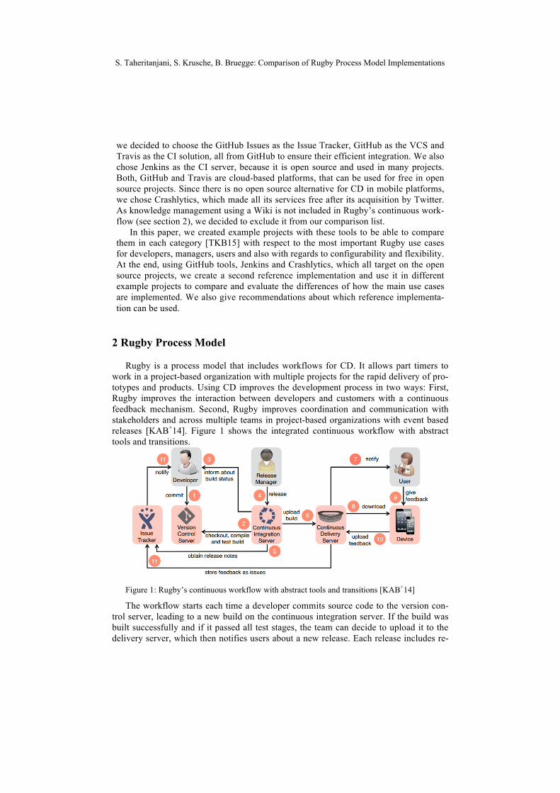
Rugby is a process model that includes workflows for CD. It allows part timers to work in a project-based organization with multiple projects for the rapid delivery of pro-totypes and products. Using CD improves the development process in two ways: First, Rugby improves the interaction between developers and customers with a continuous feedback mechanism. Second, Rugby improves coordination and communication with stakeholders and across multiple teams in project-based organizations with event based releases [KAB+14]. Figure 1 shows the integrated continuous workflow with abstract tools and transitions.
Figure 1: Rugby’s continuous workflow with abstract tools and transitions [KAB+14]
The workflow starts each time a developer commits source code to the version con-trol server, leading to a new build on the continuous integration server. If the build was built successfully and if it passed all test stages, the team can decide to upload it to the delivery server, which then notifies users about a new release. Each release includes re-
S. Taheritanjani, S. Krusche, B. Bruegge: Comparison of Rugby Process Model Implementations
lease notes, which are collected automatically by the continuous integration server and can be edited in the manual release step if necessary. The user can download the release and recognize easily, which features and bugs were resolved in that. He can use an em-bedded mechanism to give feedback in a structured way. This feedback is collected on the delivery server and forwarded to the issue tracker [KA14]. Rugby is a customizable process model that can be adapted and refined to the team’s needs [KAB+14]. It supports CSE and software evolution with one Scrum core workflow together with three additional workflows: (1) issue management needs an issue tracker, (2) review management needs a VCS, (3) release management needs a CI and a CD server, (4) feedback management needs a CD server and an issue tracker [KAB+14]. These workflows are also customizable and can be included in other agile processes, in particular Scrum and Kanban [KAB+14].
3 Comparison between Different Tools in each Workflow
For each of these workflows, we select alternatives and compare them with the corre-sponding commercial tools in the existing reference implementation with respect to the most important core use cases and non-functional requirements in each workflow. At the end of each section, there is a comparison table which shows scores for each feature of the tool (combination). Scores range from 1 (very poor quality or support) to 5 (excellent quality or support). In case a tool does not support a feature, a dash sign is shown (-).
3.1 Issue Management Workflow
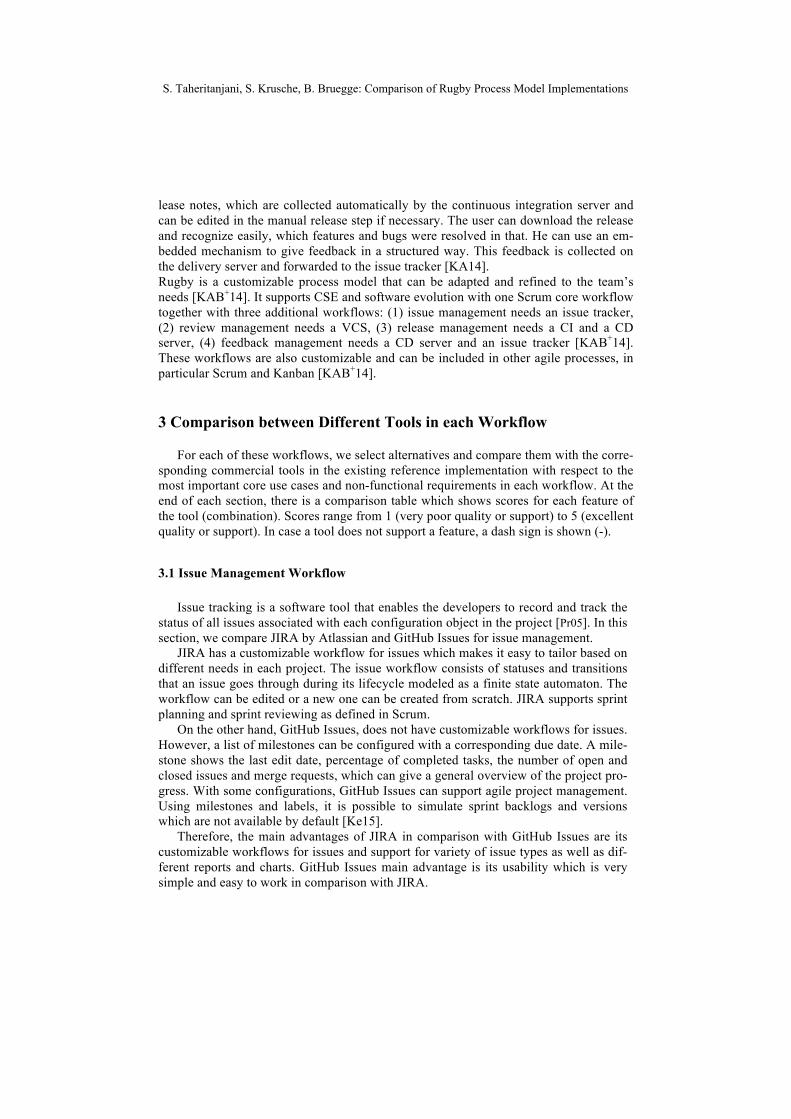
Issue tracking is a software tool that enables the developers to record and track the status of all issues associated with each configuration object in the project [Pr05]. In this section, we compare JIRA by Atlassian and GitHub Issues for issue management.
JIRA has a customizable workflow for issues which makes it easy to tailor based on different needs in each project. The issue workflow consists of statuses and transitions that an issue goes through during its lifecycle modeled as a finite state automaton. The workflow can be edited or a new one can be created from scratch. JIRA supports sprint planning and sprint reviewing as defined in Scrum.
On the other hand, GitHub Issues, does not have customizable workflows for issues. However, a list of milestones can be configured with a corresponding due date. A mile-stone shows the last edit date, percentage of completed tasks, the number of open and closed issues and merge requests, which can give a general overview of the project pro-gress. With some configurations, GitHub Issues can support agile project management. Using milestones and labels, it is possible to simulate sprint backlogs and versions which are not available by default [Ke15].
Therefore, the main advantages of JIRA in comparison with GitHub Issues are its customizable workflows for issues and support for variety of issue types as well as dif-ferent reports and charts. GitHub Issues main advantage is its usability which is very simple and easy to work in comparison with JIRA.
S. Taheritanjani, S. Krusche, B. Bruegge: Comparison of Rugby Process Model Implementations
Relevant features for Rugby JIRA GitHub Customizable issue states and transitions 5 1 Configuration possibilities 5 1 Taskboard support 5 3 Versions support 5 4 (using Labels) Backlogs support 5 3 (using Milestones) Sprint planning/review support 5 3 Usability 3 5
Table 1: Issue management workflow comparison [TKB15]
3.2 Review Management Workflow
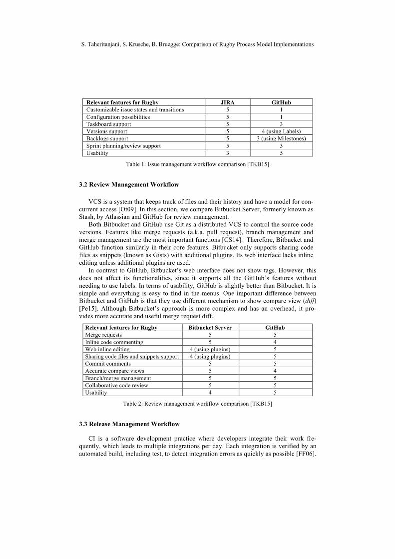
VCS is a system that keeps track of files and their history and have a model for con-current access [Ot09]. In this section, we compare Bitbucket Server, formerly known as Stash, by Atlassian and GitHub for review management.
Both Bitbucket and GitHub use Git as a distributed VCS to control the source code versions. Features like merge requests (a.k.a. pull request), branch management and merge management are the most important functions [CS14]. Therefore, Bitbucket and GitHub function similarly in their core features. Bitbucket only supports sharing code files as snippets (known as Gists) with additional plugins. Its web interface lacks inline editing unless additional plugins are used.
In contrast to GitHub, Bitbucket’s web interface does not show tags. However, this does not affect its functionalities, since it supports all the GitHub’s features without needing to use labels. In terms of usability, GitHub is slightly better than Bitbucket. It is simple and everything is easy to find in the menus. One important difference between Bitbucket and GitHub is that they use different mechanism to show compare view (diff) [Pe15]. Although Bitbucket’s approach is more complex and has an overhead, it pro-vides more accurate and useful merge request diff.
Relevant features for Rugby Bitbucket Server GitHub Merge requests 5 5 Inline code commenting 5 4 Web inline editing 4 (using plugins) 5 Sharing code files and snippets support 4 (using plugins) 5 Commit comments 5 5 Accurate compare views 5 4 Branch/merge management 5 5 Collaborative code review 5 5 Usability 4 5
Table 2: Review management workflow comparison [TKB15]
3.3 Release Management Workflow
CI is a software development practice where developers integrate their work fre-quently, which leads to multiple integrations per day. Each integration is verified by an automated build, including test, to detect integration errors as quickly as possible [FF06].
S. Taheritanjani, S. Krusche, B. Bruegge: Comparison of Rugby Process Model Implementations
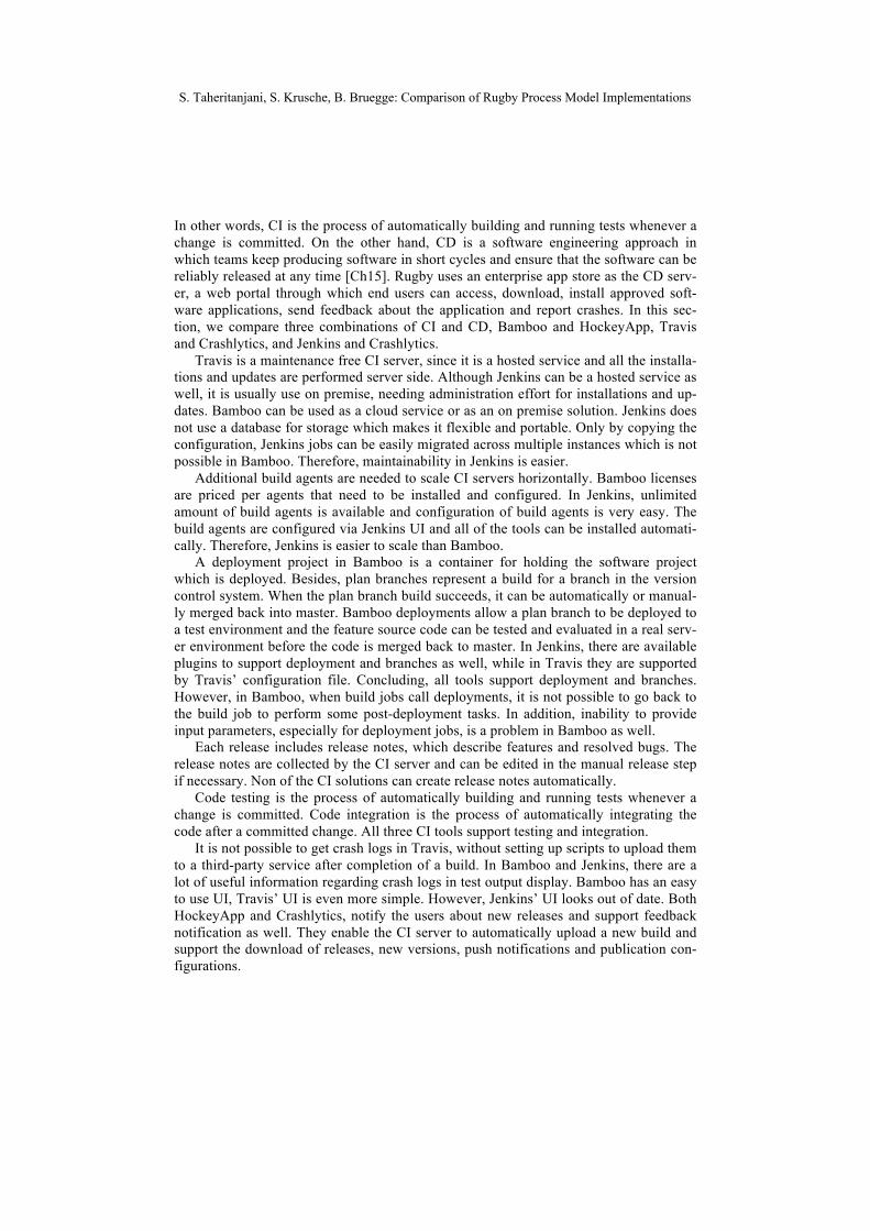
In other words, CI is the process of automatically building and running tests whenever a change is committed. On the other hand, CD is a software engineering approach in which teams keep producing software in short cycles and ensure that the software can be reliably released at any time [Ch15]. Rugby uses an enterprise app store as the CD serv-er, a web portal through which end users can access, download, install approved soft-ware applications, send feedback about the application and report crashes. In this sec-tion, we compare three combinations of CI and CD, Bamboo and HockeyApp, Travis and Crashlytics, and Jenkins and Crashlytics.
Travis is a maintenance free CI server, since it is a hosted service and all the installa-tions and updates are performed server side. Although Jenkins can be a hosted service as well, it is usually use on premise, needing administration effort for installations and up-dates. Bamboo can be used as a cloud service or as an on premise solution. Jenkins does not use a database for storage which makes it flexible and portable. Only by copying the configuration, Jenkins jobs can be easily migrated across multiple instances which is not possible in Bamboo. Therefore, maintainability in Jenkins is easier.
Additional build agents are needed to scale CI servers horizontally. Bamboo licenses are priced per agents that need to be installed and configured. In Jenkins, unlimited amount of build agents is available and configuration of build agents is very easy. The build agents are configured via Jenkins UI and all of the tools can be installed automati-cally. Therefore, Jenkins is easier to scale than Bamboo.
A deployment project in Bamboo is a container for holding the software project which is deployed. Besides, plan branches represent a build for a branch in the version control system. When the plan branch build succeeds, it can be automatically or manual-ly merged back into master. Bamboo deployments allow a plan branch to be deployed to a test environment and the feature source code can be tested and evaluated in a real serv-er environment before the code is merged back to master. In Jenkins, there are available plugins to support deployment and branches as well, while in Travis they are supported by Travis’ configuration file. Concluding, all tools support deployment and branches. However, in Bamboo, when build jobs call deployments, it is not possible to go back to the build job to perform some post-deployment tasks. In addition, inability to provide input parameters, especially for deployment jobs, is a problem in Bamboo as well.
Each release includes release notes, which describe features and resolved bugs. The release notes are collected by the CI server and can be edited in the manual release step if necessary. Non of the CI solutions can create release notes automatically.
Code testing is the process of automatically building and running tests whenever a change is committed. Code integration is the process of automatically integrating the code after a committed change. All three CI tools support testing and integration.
It is not possible to get crash logs in Travis, without setting up scripts to upload them to a third-party service after completion of a build. In Bamboo and Jenkins, there are a lot of useful information regarding crash logs in test output display. Bamboo has an easy to use UI, Travis’ UI is even more simple. However, Jenkins’ UI looks out of date. Both HockeyApp and Crashlytics, notify the users about new releases and support feedback notification as well. They enable the CI server to automatically upload a new build and support the download of releases, new versions, push notifications and publication con-figurations.
S. Taheritanjani, S. Krusche, B. Bruegge: Comparison of Rugby Process Model Implementations
Relevant features for Rugby Bamboo + HockeyApp
Travis + Crashlytics
Jenkins + Crashlytics
Build plan configuration 5 4 4 New commit/branch detection 5 4 4 Release notes creation - - - Testing 5 5 5 Integration 5 5 5 Build status notification 5 2 5 Deploy build to CD server 4 5 5 Feedback/new release notification 5 5 5 App version automatic upload 5 5 5 Release download 5 4 4 CI scalability 3 - 5 CI maintainability 3 5 4 CI usability 4 5 2 App version download usability for the user 5 4 4 Support of multiple mobile platforms 5 4 (iOS,
Android) 4 (iOS,
Android)
Table 3: Release management workflow comparison [TKB15]
3.4 Feedback Management Workflow
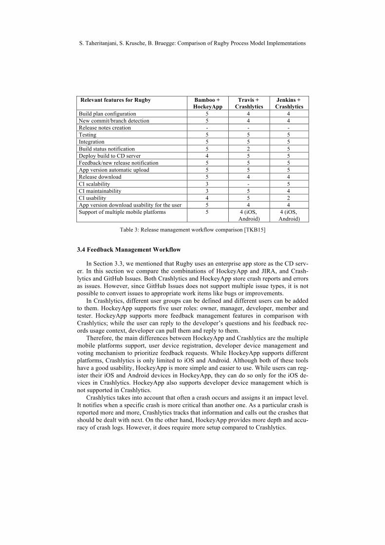
In Section 3.3, we mentioned that Rugby uses an enterprise app store as the CD serv-er. In this section we compare the combinations of HockeyApp and JIRA, and Crash-lytics and GitHub Issues. Both Crashlytics and HockeyApp store crash reports and errors as issues. However, since GitHub Issues does not support multiple issue types, it is not possible to convert issues to appropriate work items like bugs or improvements.
In Crashlytics, different user groups can be defined and different users can be added to them. HockeyApp supports five user roles: owner, manager, developer, member and tester. HockeyApp supports more feedback management features in comparison with Crashlytics; while the user can reply to the developer’s questions and his feedback rec-ords usage context, developer can pull them and reply to them.
Therefore, the main differences between HockeyApp and Crashlytics are the multiple mobile platforms support, user device registration, developer device management and voting mechanism to prioritize feedback requests. While HockeyApp supports different platforms, Crashlytics is only limited to iOS and Android. Although both of these tools have a good usability, HockeyApp is more simple and easier to use. While users can reg-ister their iOS and Android devices in HockeyApp, they can do so only for the iOS de-vices in Crashlytics. HockeyApp also supports developer device management which is not supported in Crashlytics.
Crashlytics takes into account that often a crash occurs and assigns it an impact level. It notifies when a specific crash is more critical than another one. As a particular crash is reported more and more, Crashlytics tracks that information and calls out the crashes that should be dealt with next. On the other hand, HockeyApp provides more depth and accu-racy of crash logs. However, it does require more setup compared to Crashlytics.
S. Taheritanjani, S. Krusche, B. Bruegge: Comparison of Rugby Process Model Implementations
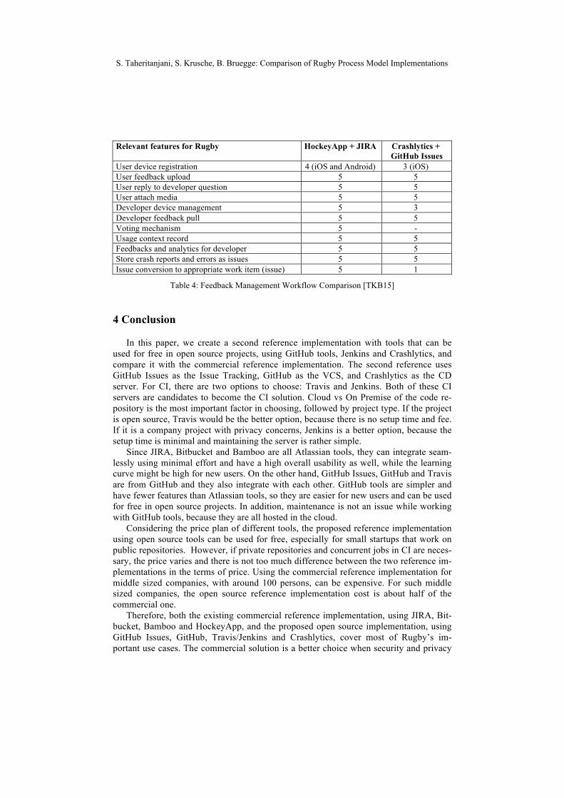
Relevant features for Rugby HockeyApp + JIRA Crashlytics + GitHub Issues
User device registration 4 (iOS and Android) 3 (iOS) User feedback upload 5 5 User reply to developer question 5 5 User attach media 5 5 Developer device management 5 3 Developer feedback pull 5 5 Voting mechanism 5 - Usage context record 5 5 Feedbacks and analytics for developer 5 5 Store crash reports and errors as issues 5 5 Issue conversion to appropriate work item (issue) 5 1
Table 4: Feedback Management Workflow Comparison [TKB15]
4 Conclusion
In this paper, we create a second reference implementation with tools that can be used for free in open source projects, using GitHub tools, Jenkins and Crashlytics, and compare it with the commercial reference implementation. The second reference uses GitHub Issues as the Issue Tracking, GitHub as the VCS, and Crashlytics as the CD server. For CI, there are two options to choose: Travis and Jenkins. Both of these CI servers are candidates to become the CI solution. Cloud vs On Premise of the code re-pository is the most important factor in choosing, followed by project type. If the project is open source, Travis would be the better option, because there is no setup time and fee. If it is a company project with privacy concerns, Jenkins is a better option, because the setup time is minimal and maintaining the server is rather simple.
Since JIRA, Bitbucket and Bamboo are all Atlassian tools, they can integrate seam-lessly using minimal effort and have a high overall usability as well, while the learning curve might be high for new users. On the other hand, GitHub Issues, GitHub and Travis are from GitHub and they also integrate with each other. GitHub tools are simpler and have fewer features than Atlassian tools, so they are easier for new users and can be used for free in open source projects. In addition, maintenance is not an issue while working with GitHub tools, because they are all hosted in the cloud.
Considering the price plan of different tools, the proposed reference implementation using open source tools can be used for free, especially for small startups that work on public repositories. However, if private repositories and concurrent jobs in CI are neces-sary, the price varies and there is not too much difference between the two reference im-plementations in the terms of price. Using the commercial reference implementation for middle sized companies, with around 100 persons, can be expensive. For such middle sized companies, the open source reference implementation cost is about half of the commercial one.
Therefore, both the existing commercial reference implementation, using JIRA, Bit-bucket, Bamboo and HockeyApp, and the proposed open source implementation, using GitHub Issues, GitHub, Travis/Jenkins and Crashlytics, cover most of Rugby’s im-portant use cases. The commercial solution is a better choice when security and privacy
S. Taheritanjani, S. Krusche, B. Bruegge: Comparison of Rugby Process Model Implementations
are important and repositories should be private. On the other hand, when the project can be public, the open source solution should be preferred. Rugby can be implemented with different tools, either for commercial projects or open source projects. However, there is always a tradeoff between the tools quality and their price. It remains to compare other tools for their use in Rugby projects in the future works.
References
[FS14] B. Fitzgerald, K.J. Stol: "Continuous software engineering and beyond: trends and challenges." Proceedings of the 1st International Workshop on Rapid Continuous Software Engineering. ACM, 2014.
[Bo14] J. Bosch: “Continuous software engineering: An introduction,” in Continuous Soft-ware Engineering. Springer, 2014; Pages 3–13.
[Sc04] K. Schwaber: Agile project management with Scrum. Microsoft Press, 2004; Chap-ter 4.
[JBR+99] I. Jacobson, G. Booch, J. Rumbaugh, J. Rumbaugh, G. Booch: The unified software development process. Addison-wesley, 1999; Page 92.
[HF10] J. Humble, D. Farley: Continuous delivery: reliable software releases through build, test, and deployment automation. Pearson Education, 2010; Pages 24-29.
[KAB+14] S. Krusche, L. Alperowitz, B. Bruegge, M. O. Wagner, Rugby: An Agile Process Model Based on Continuous Delivery, Proceedings of the 1st International Workshop on Rapid Continuous Software Engineering. ACM, 2014.
[KKP+15] S. Klepper, S. Krusche, S. Peters, B. Bruegge, L. Alperowitz: Introducing Continu-ous Delivery of Mobile Apps in a Corporate Environment: A Case Study, 2015.
[BKA15] B. Bruegge, S. Krusche, L. Alperowitz: Software Engineering Project Courses with Industrial Clients, ACM Transactions on Computing Education, 2015.
[Pr05] R.S. Pressman: Software engineering: a practitioner's approach (7th Edition). Pal-grave Macmillan, 2010; Page 595.
[KA14] S. Krusche, L. Alperowitz: Introduction of Continuous Delivery in Multi-Customer Project Courses, Proceedings of the 36th International Conference on Software Engi-neering, 2014; Pages 2-3.
[Ke15] H. Kellaway: Using Github for Lightweight Software Project Management, 2015. Retrieved 06-October-2015 from http://harlankellaway.com/blog/2015/04/02/using-github-issues-for-software-project-management/
[Ot09] S. Otte.: Version Control Systems. Computer Systems and Telematics, 2009 Institute of Computer Science, Freie Universität, Berlin, Germany.
[CS14] S. Chacon, B. Straub: Pro Git (2nd Edition). Apress, 2014; Pages 89-98. [Pe15] T. Petterson: A better pull request, 2015. Retrieved 13-September-2015 from
https://developer.atlassian.com/blog/2015/01/a-better-pull-request/ [FF06] M. Fowler, M. Foemmel: Continuous integration. Thought-Works)
http://www.thoughtworks.com/ContinuousIntegration.Pdf, 2006. [Ch15] L. Chen: Continuous Delivery: Huge Benefits, but Challenges Too. Software, IEEE,
2015. [TKB15] S. Taheritanjani, S. Krusche, B. Bruegge: A Comparison between Commercial and
Open Source Reference Implementations for the Rugby Process Model, A University Research Report, 2016.
S. Taheritanjani, S. Krusche, B. Bruegge: Comparison of Rugby Process Model Implementations
Toward Integrating a System Theoretic Safety Analysis inan Agile Development Process
Yang Wang, Stefan WagnerInstitute of Software TechnologyUniversity of Stuttgart, Germany
{yang.wang, stefan.wagner}@informatik.uni-stuttgart.de
Abstract: Agile development methodologies are becoming a tendency in today’s chan-ging software development. However, due to a lack of safety assurance activities,especially safety analysis, agile methods are criticized for being inadequate for thedevelopment of safe software. In this paper, we introduce an agile ”Safe Scrum” bymapping a novel systematic safety analysis method, called STPA (System-TheoreticProcess Analysis) into an existing agile development process ”Safe Scrum” for safety-critical systems. This work is done by (1) performing safety-guided design inside eachsprint, and (2) replacing the traditional RAMS (Reliability, Availability, Maintenance,and Safety) validation. We aim to extend Safe Scrum by integrating STPA, to find abalance point between Safe Scrum and basic Scrum.
1 IntroductionTo apply agile methodologies into safety-critical systems, most research prefers combiningagile methods with traditional development processes relying on safety standards. Howe-ver, little emphysis is put on the nature of agile techniques, which prevents the proceedingof traditional safety assurance activitie−a continuously changing architecture design. Pro-blem Statement: (1) the lack of safety assurance activities, especially safety analysis inagile methodologies prevents the application of agile methods in safety-critical systems.(2) Current safety analysis technologies are inadequate for agile methods due to a lackof a stable architecture design. Research Objective: The main objective of this articleis to integrate a novel systematic safety analysis technology STPA [Lev11] into an exis-ting agile development process ”Safe Scrum” [SMH12] guiding safe architecture design.Contribution: (1) STPA drives the safe architecture design in Safe Scrum. (2) ApplyingSTPA to the final product of each sprint instead of the traditional complicated RAMS (Re-liability, Availability, Maintenance and Safety) validation, which makes Safe Scrum moreagile. (3) we introduce the first concept of mapping STPA into agile software developmentprocesses. This article is a position paper, where the extension of Safe Scrum is still in theconcept stage. A student project is planned in the future to further explore and investigatethe development process.
2 Related WorkThere has been little experience published on the utilization of safety analysis technologiesin agile development methodologies. Most of the research is from the viewpoint of a hybrid
Copyright © 2016 for the individual papers by the papers' authors. Copying permitted for private and academic purposes. This volume is published and copyrighted by its editors.
Y. Wang, S. Wagner: Safety Analysis in an Agile Development Process
development process model to accept agile methods in safety-critical systems. Safe Scrum,proposes by Stalhane, Myklebust and Hanssen [SMH12], is motivated by the need to makeit possible to use methods that are flexible with respect to planning, documentation andspecification while still being acceptable to IEC 61508 [IEC04], as well as making Scruma practically useful approach for developing safety-critical systems.
Undoubtedly, Safe Scrum is a considerable success for its innovative combination. Ho-wever, too much adherance to the safety standard IEC 61508 makes the process lackingagility. First, all the additional safety assurance activities are kept outside Scrum. Littlefocus is put on the incremental architectures inside each sprint. Second, each sprint inScrum should be swarming [Rub12] rather than sequential as mini waterfall or mini V-model [SMH12]. We believe that safety-guided design is strongly needed in agile methodsinstead of the purely ”add-on” safety assurance.
In addition, Ge et al. [GPM+10] published an iterative approach to develop safety-criticalsoftware. Vuori [Vuo11] proposed a hybrid model like Safe Scrum. However, both of themsuggest an up-front design, which is not recommended in Scrum [Coh10].
In comparison to the research above, we try to find out a suitable safety analysis techniquefor agile methods, to abandon this heavy weight architecture ahead and still keep safety inagile methods.
3 BackgroundWe suggest STPA to confront the aforementioned problems. It is a new hazard analysistechnique based on systems thinking and a new model of accident causation based onsystems theory rather than reliability theory. It consists of two main steps: (1) Identifythe potential for inadequate control of the system that could lead to a hazardous state. (2)Determine how each potentially hazardous control action identified in step 1 could oc-cur [Lev11]. We recommend this novel technique for two reasons: (1) The current safetyanalysis techniques, such as FMEA (Failure Mode and Effects Analysis) or FTA (FaultTree Analysis), assume that accidents are caused by component failures, which is not truefor software. The primary advantage of STPA is that it emphasises causal factors fromthe system view, such as component interaction accidents or cognitively complex humandecision-making errors. (2) Current safety analysis techniques start from a complete de-sign, which is not consistent to agile development methodologies. STPA, however, provi-des the necessary information to guide the design process.
4 ConceptIn this section, we integrate STPA in Safe Scrum. To clarify our approach, we use theairbag system as an example.
We extend Safe Scrum in three aspects: (1) During each sprint we integrate STPA as safety-guided design. (2) At the end of each sprint, we use STPA on the product instead of aRAMS validation. (3) We replace the final RAMS validation with STPA. The other partswhich are still kept consistent to Safe Scrum are: (1) The environment description and theSSRS phases 1-4. (2) Test Driven Development. (3) Safety product backlog. (4) A safety
Y. Wang, S. Wagner: Safety Analysis in an Agile Development Process
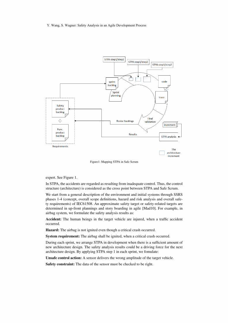
Figure1: Mapping STPA in Safe Scrum
expert. See Figure 1.
In STPA, the accidents are regarded as resulting from inadequate control. Thus, the controlstructure (architecture) is considered as the cross point between STPA and Safe Scrum.
We start from a general description of the environment and initial systems through SSRSphases 1-4 (concept, overall scope definitions, hazard and risk analysis and overall safe-ty requirements) of IEC61508. An approximate safety target or safety-related targets aredetermined in up-front plannings and story boarding in agile [Mad10]. For example, inairbag system, we formulate the safety analysis results as:
Accident: The human beings in the target vehicle are injured, when a traffic accidentoccurred.
Hazard: The airbag is not ignited even though a critical crash occurred.
System requirement: The airbag shall be ignited, when a critical crash occurred.
During each sprint, we arrange STPA in development when there is a sufficient amount ofnew architecture design. The safety analysis results could be a driving force for the nextarchitecture design. By applying STPA step 1 in each sprint, we fomulate:
Unsafe control action: A sensor delivers the wrong amplitude of the target vehicle.
Safety constraint: The data of the sensor must be checked to be right.
Y. Wang, S. Wagner: Safety Analysis in an Agile Development Process
This constraint is translated as a safety requirement for the following architecture design.By applying STPA step 2, the factors that could lead to violate the safety constraints aredetermined. More detailed safety requirements are to be elicited depending on the stepwisesystem design.
After each sprint, a product is created. We finally apply STPA to it for the following rea-sons: (1) Getting a final safety assessment. (2) Combining with safety verification in thesystem level. (3) Driving the next sprint development.
All the safety analysis activities aforementioned are executed by a safety expert and theresults are documented in the safety product backlog.
5 Conclusion and Future workIn this paper, we propose an agile ”Safe Scrum” by integrating STPA to perform safety-guided design instead of adding traditional safety-related assurance methodologies on it.Traditionally successful safety analysis technologies are based on traditional developmentprocess. It′s not certain if they can solve the safety-related problems caused by the natureof agile development methodologies. Rather than a hybrid combination between traditio-nal safety standard and agile development process, it would be a good direction from thestandpoint of the nature in agile methods and try to find out more safety assurance techno-logies, which are commit to and get use of the agile principles. For future work, we focuson the verification between safety requirements from STPA and the code under develop-ment.
Literatur
[Coh10] Mike Cohn. Succeeding with agile: software development using Scrum. Pearson Edu-cation, 2010.
[GPM+10] Xiaocheng Ge, Richard F Paige, John McDermid et al. An iterative approach for deve-lopment of safety-critical software and safety arguments. In Agile Conference (AGILE),2010, Seiten 35–43. IEEE, 2010.
[IEC04] IEC. IEC61508, Functional safety of electrical/electronic/programmable electronicsafety-related systems. International Electrotechnical Commission, 2010-04.
[Lev11] Nancy Leveson. Engineering a safer world: Systems thinking applied to safety. MitPress, 2011.
[Mad10] James Madison. Agile architecture interactions. Software, IEEE, 27(2):41–48, 2010.
[Rub12] Kenneth S Rubin. Essential Scrum: A practical guide to the most popular Agile process.Addison-Wesley, 2012.
[SMH12] T Stalhane, T Myklebust und GK Hanssen. The application of Safe Scrum to IEC 61508certifiable software. Haettu, 1:2014, 2012.
[Vuo11] Matti Vuori. Agile development of safety-critical software. Tampere University ofTechnology. Department of Software Systems; 14, 2011.
Y. Wang, S. Wagner: Safety Analysis in an Agile Development Process
Designing an Android continuous delivery pipeline
Milena Zachow
Fachbereich 3: Information & Kommunikation University of Applied Sciences Flensburg
Kanzleistraße 91-93 D-24943 Flensburg
Abstract: Mobile applications (apps) are increasingly popular and run on a wide range of different operating systems and devices. Fragmentation is one of the differences between mobile apps and web- or desktop based applications and presents a challenge in delivering high quality apps. Automated testing can help to overcome it. This paper presents a case study on designing a continuous delivery pipeline for an Android app focused on simple setup.
1 Introduction
The use of mobile devices grows significantly. Mobile apps are different from traditional web- or desktop based applications in many respects. They run on highly fragmented devices and operating systems, use a variety of inputs from user and environment (e.g. sensor inputs, speech or gestures) and have limited resources (e.g. CPU, memory and battery power).
In web- and desktop continuous delivery is an important topic. Automation is necessary to ensure quality; the automated build and test steps are called continuous delivery pipeline [HF10]. In mobile app development continuous delivery and test automation culture is different [Ko15].
This paper describes the development of the mobile Android app MedTabImager that visualizes medical CT/MR slice images. MedTabImager is made of roughly 20k LOC. Rendering is based on OpenGL ES. The unit test code coverage varies between 39% in some packages (e.g. configuration or util) and single-digit numbers in in view-related packages (e.g. components). 2 developers implemented 30 user stories in a 9-month period (part time). Instrumentation tests exist for some of the user stories. Although in the medical domain software quality is important and tests exist, the developers did not set up a continuous delivery pipeline. That leads to the question:
RQ1: What are the challenges in setting up a continuous delivery pipeline for Android apps?
Copyright © 2016 for the individual papers by the papers' authors. Copying permitted for private and academic purposes. This volume is published and copyrighted by its editors.
M. Zachow: Designing an Android continuous delivery pipeline
The MedTabImager developers set up a continuous integration (CI) server, but did not use it for automated testing. The reasons were technical challenges in making the CI work with the emulator or real devices. After spending a certain amount of effort (see Tab. 1) without satisfying results the developers gave up on the task.
Therefore one of the challenges in setting up a continuous delivery pipeline for apps is:
C1: Minimize the effort of the setup
There are other challenges as well. To name a few: the Android emulator is slow and unstable. UITests on the OpenGL level are hard to implement. Some sensor data is difficult to mock. This paper focuses on minimizing the pipeline’s setup effort.
2 Related work
Continuous delivery is a topic in research [Fe13] but is often focused on building large web-based systems (e.g. at companies like Facebook or Amazon).
In the context of mobile apps, especially Android, automated testing is widely discussed in academic research and industry. Google just recently added full support of unit testing in Android studio (an experimental support exists since Version 1.11). They also offer different solutions for testing Android lifecycle code and integration tests. For UI testing Google’s current solution is a tool called UIAutomator2. Additionally, lots of commercial and free testing tools exist.
There have been many studies on testing techniques for mobile app development, especially Android. Tools for automated test case generation have been proposed as well as different approaches to automate UI testing with the capture and replay approach [Ch14]. Cloudbased solutions or Testing as a Service (TaaS) are widely discussed in both industry and research, judging by extensive research [Ga14]. Test automation is possibly the only way to deal with the continuing fragmentation [KK13]. However, in the mobile app development context the level of test automation is quite low. Studies on test coverage in open source Android apps suggest that a majority of the apps studies do not have any tests cases at all – nearly 86% [Ko15]. Automated testing does not seem to be widely accepted by Android developers.
The technical challenges to achieve continuous delivery on top of automated tests for mobile apps are seldom addressed in research. Continuous delivery of mobile applications is studied but with a focus on the process [Kl15].
1 http://tools.android.com/tech-docs/unit-testing-support 2 http://developer.android.com/tools/testing/index.html
M. Zachow: Designing an Android continuous delivery pipeline
3 Minimize setup effort with TaaS
The MedTabImager developers aimed at following steps for their automated build: compile and package the app (using the build management tool Gradle), run unit tests, run UI tests, send an apk file to beta users and deploy to a marketplace. They failed to manually set up UI tests on a continuous integration server (Jenkins) in a reasonable amount of time.
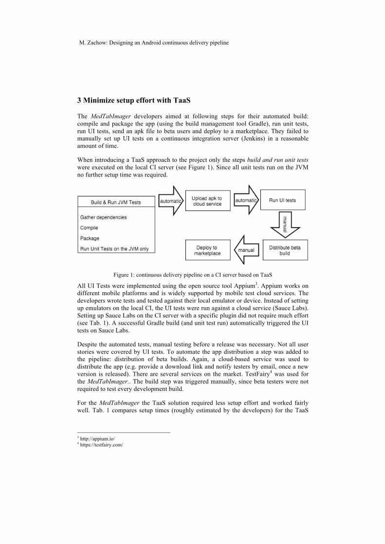
When introducing a TaaS approach to the project only the steps build and run unit tests were executed on the local CI server (see Figure 1). Since all unit tests run on the JVM no further setup time was required.
Figure 1: continuous delivery pipeline on a CI server based on TaaS
All UI Tests were implemented using the open source tool Appium3. Appium works on different mobile platforms and is widely supported by mobile test cloud services. The developers wrote tests and tested against their local emulator or device. Instead of setting up emulators on the local CI, the UI tests were run against a cloud service (Sauce Labs). Setting up Sauce Labs on the CI server with a specific plugin did not require much effort (see Tab. 1). A successful Gradle build (and unit test run) automatically triggered the UI tests on Sauce Labs.
Despite the automated tests, manual testing before a release was necessary. Not all user stories were covered by UI tests. To automate the app distribution a step was added to the pipeline: distribution of beta builds. Again, a cloud-based service was used to distribute the app (e.g. provide a download link and notify testers by email, once a new version is released). There are several services on the market. TestFairy4 was used for the MedTabImager.. The build step was triggered manually, since beta testers were not required to test every development build.
For the MedTabImager the TaaS solution required less setup effort and worked fairly well. Tab. 1 compares setup times (roughly estimated by the developers) for the TaaS
3 http://appium.io/ 4 https://testfairy.com/
M. Zachow: Designing an Android continuous delivery pipeline
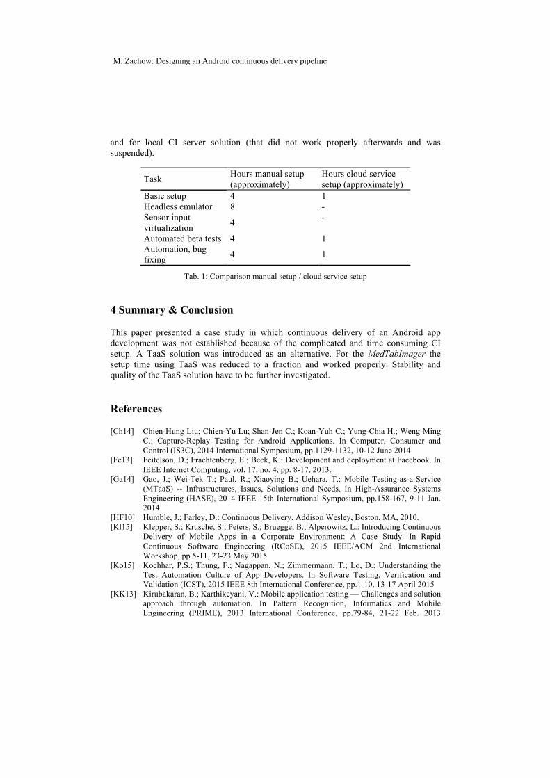
and for local CI server solution (that did not work properly afterwards and was suspended).
Task Hours manual setup (approximately)
Hours cloud service setup (approximately)
Basic setup 4 1 Headless emulator 8 - Sensor input virtualization 4 -
Automated beta tests 4 1 Automation, bug fixing 4 1
Tab. 1: Comparison manual setup / cloud service setup
4 Summary & Conclusion
This paper presented a case study in which continuous delivery of an Android app development was not established because of the complicated and time consuming CI setup. A TaaS solution was introduced as an alternative. For the MedTabImager the setup time using TaaS was reduced to a fraction and worked properly. Stability and quality of the TaaS solution have to be further investigated.
References
[Ch14] Chien-Hung Liu; Chien-Yu Lu; Shan-Jen C.; Koan-Yuh C.; Yung-Chia H.; Weng-Ming C.: Capture-Replay Testing for Android Applications. In Computer, Consumer and Control (IS3C), 2014 International Symposium, pp.1129-1132, 10-12 June 2014
[Fe13] Feitelson, D.; Frachtenberg, E.; Beck, K.: Development and deployment at Facebook. In IEEE Internet Computing, vol. 17, no. 4, pp. 8-17, 2013.
[Ga14] Gao, J.; Wei-Tek T.; Paul, R.; Xiaoying B.; Uehara, T.: Mobile Testing-as-a-Service (MTaaS) -- Infrastructures, Issues, Solutions and Needs. In High-Assurance Systems Engineering (HASE), 2014 IEEE 15th International Symposium, pp.158-167, 9-11 Jan. 2014
[HF10] Humble, J.; Farley, D.: Continuous Delivery. Addison Wesley, Boston, MA, 2010. [Kl15] Klepper, S.; Krusche, S.; Peters, S.; Bruegge, B.; Alperowitz, L.: Introducing Continuous
Delivery of Mobile Apps in a Corporate Environment: A Case Study. In Rapid Continuous Software Engineering (RCoSE), 2015 IEEE/ACM 2nd International Workshop, pp.5-11, 23-23 May 2015
[Ko15] Kochhar, P.S.; Thung, F.; Nagappan, N.; Zimmermann, T.; Lo, D.: Understanding the Test Automation Culture of App Developers. In Software Testing, Verification and Validation (ICST), 2015 IEEE 8th International Conference, pp.1-10, 13-17 April 2015
[KK13] Kirubakaran, B.; Karthikeyani, V.: Mobile application testing — Challenges and solution approach through automation. In Pattern Recognition, Informatics and Mobile Engineering (PRIME), 2013 International Conference, pp.79-84, 21-22 Feb. 2013
M. Zachow: Designing an Android continuous delivery pipeline
On Optimization of Test Parallelization with Constraints
Masoumeh Parsa, Adnan Ashraf, Dragos Truscan, and Ivan Porres
Abstract: Traditionally, test cases are executed sequentially due to the dependencyof test data. For large system level test suites, when a test session can take hours oreven days, sequential execution does not satisfy any more the industrial demands forshort lead times and fast feed-back cycles. Parallel test execution has appeared as anappealing option to cut down on the test execution time. However, running tests inparallel is not a trivial task due to dependencies and constraints between tests cases.Therefore, we propose an approach to parallelize test execution based on the availableresources, constraints between tests, and the duration of tests that creates parallel testexecution schedules that can be run in multiple testing environments simultaneously.We formulate and solve the problem as Ant Colony System, in order to find a near-optimal solution.
1 Introduction
The number of test cases required to ensure the quality of a software system grows hand-in-hand with its complexity, and consequently, the total test execution time increases pro-portionally. For large software systems, test execution time becomes increasingly criticalin automated regression testing, where a large suite of tests is executed frequently on con-tinuous integration servers.
Different approaches like test selection, test prioritization or test case reduction are typical-ly used to speed up test execution, especially in the context of regression testing [YH12].However, these improvements can be limited for large test suites.
Test suites are trivially parallelizable if tests are independent, that is, if one test does notrely on the system state established by a previous test and it is free of interference fromother tests. An example of an interference is when two or more tests require exclusiveaccess to a shared resource such as a database. However, one cannot always assume thatthese conditions hold and tests that pass when executed in a certain sequence may failunder trivial parallelization. A third, perhaps less obvious but even more important issueis what we refer to as state incompatibility. In this case, one test may leave the systemin a state from which another test cannot proceed. One concrete example of this is a testthat deletes data from a database that is expected by other tests. While such cases canoften be handled by resetting the system under test to a known initial state, resets can betime-consuming and an efficient test execution approach should strive to minimize or evenremove the need for system resets.
Although test designers may strive to create independent test cases, recent studies showthat in practice tests are often not completely independent [ZJW+14, BMDK15], whileother researchers consider these useful and exploit test dependencies [HM13]. As a conse-
Copyright © 2016 for the individual papers by the papers' authors. Copying permitted for private and academic purposes. This volume is published and copyrighted by its editors.
M. Parsa, A. Ashraf, D. Truscan, I. Porres: Optimization of Test Parallelization
quence, there is a need to plan and schedule the execution of complex test suites in orderto avoid undesired interactions between tests and time consuming system resets. Althoughit is possible to create a test schedule manually, this is not viable in practice if the numberof tests is large. To address this issue, we propose an approach to build test schedules au-tomatically by analyzing known dependencies among tests and their execution time. Thedependencies between the tests can be derived automatically [ZJW+14] or defined manu-ally [dep]. The scheduler is run before each integration testing while preparing the systemunder test. We aim to find the best possible groups and order of tests in each group to bedistributed between a number of agents which share or do not share the same resourceswith the objective of reducing the total time that is required for all the tests to be exe-cuted. The other objective is to decrease the number of failed tests which are caused bythe dependencies between the tests. We define the relations between the tests as a set ofconstraints in scheduling problems. The first objective of the work is to reduce the testsfailing due to their state incompatibilities, interferences or dependencies while executingin parallel. The second objective is to minimize the test execution time of the entire testsuite, by searching for the best possible ordering of tests between different agents.
2 Background and Related Work
Recent work exploits test case dependencies as a means for prioritization of test suites[HM13], online reduction of test suites [AMPW15], or for protocol conformance testingin the context of distributed systems [MGM15]. Other works investigate how test depen-dencies can be detected in order to improve the independence of test cases [GSHM15] orto shorten the test execution time by minimizing the number of database resets [HKK05].However, none of these works investigated approaches for executing tests in parallel.
Haftmann et al. propose an approach for running test cases in parallel [HKL05]. The ap-proach involves partitioning the test sequences between test executors and ordering theexecution sequence on each executor, as an extension of their work in [HKK05], in whichthree scheduling strategies were proposed for resolving the test incompatibilities on data-base applications systems with minimum number of resets.
In the previously mentioned paper, the constraints that are taken into consideration are theincompatibility and interference constraints between the tests. However, we also cover thedependency constraint. Furthermore, the goal of reordering the tests in previous works isto reduce the system reset in order to reduce the test execution time, but we are aiming ongenerating a near optimal schedule which satisfy the constraint and reduce the total testexecution time.
Since test scheduling optimization is a complex combinatorial optimization problem, it iscomputationally expensive to find an exact solution for a very large number of test cases.Therefore, we formulate it as a search problem and apply a highly adaptive online optimi-zation [HLS+13] approach called Ant Colony Optimization (ACO) [DG97] to find a near-optimal solution in polynomial time. There are a number of ant algorithms, such as, AntSystem (AS), Max-Min AS (MMAS), and Ant Colony System (ACS) [DDCG99] [DG97].ACS [DDCG99] was introduced to improve the performance of AS and it is currently oneof the best performing ant algorithms. Therefore, in this paper, we apply ACS to the testscheduling optimization problem.
M. Parsa, A. Ashraf, D. Truscan, I. Porres: Optimization of Test Parallelization
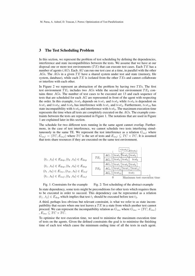
3 The Test Scheduling Problem
In this section, we represent the problem of test scheduling by defining the dependencies,interference and state incompatibilities between the tests. We assume that we have at ourdisposal one or more test environments (TE) that can execute test cases. Each TE has anumber of agents (AG). Each AG can run one test case at a time, in parallel with the otherAGs. The AGs in a given TE have a shared system under test and state (memory, filesystem, database), while each TE is isolated from the other TEs and cannot collaborateor interfere with each other.
In Figure 2 we represent an abstraction of the problem by having two TEs. The firsttest environment TE1 includes two AGs while the second test environment TE2 con-tains three AGs. The number of test cases to be executed are 13 and each sequence oftests that are scheduled for each AG are represented in front of the agent with respectingthe order. In this example, test3 depends on test1 and test2 while test9 is dependent ontest1 and test8; and test8 has interference with test1 and test2. Furthermore, test10 hasstate incompatibility with test6 and interference with test9. The maximum execution timerepresents the time when all tests are completely executed on the AGs. The example cons-traints between the tests are represented in Figure 1. The notations that are used in Figure1 are explained later in this section.
The schedule for two different tests running in the same agent cannot overlap. Further-more, in the case of test interference, we cannot schedule two tests interfering simul-taneously in the same TE. We represent the test interference as a relation Ginf whereGinf = (TC,Einf ) where TC is the set of tests and Einf ⊆ TC × TC. It is assumedthat tests share resources if they are executed on the same test environment.
(t1 , t3) ∈ Edep, (t2 , t3) ∈ Edep
(t1 , t9) ∈ Edep, (t8 , t9) ∈ Edep
(t1 , t9) ∈ Einc, (t10 , t9) ∈ Einf
(t1 , t8) ∈ Einf , (t2 , t8) ∈ Einf
Fig. 1: Constraints for the example
AG1
AG2
AG3
AG4
AG5
TE1
TE2
0t
test1 test2 test3
test4 test5 test6
test1 test8 test9
test10 test11 test12
test13 test7
Maximum test execution time
τ(test2) δ(test3)
Fig. 2: Test scheduling of the abstract exampleIn state dependency, some tests might be preconditions for other tests which requires themto be executed in order to succeed. This dependency can be represented as a relation(t1 , t2) ∈ Edep which implies that test t1 should be executed before test t2.
A third, perhaps less obvious but relevant constraint, is what we refer to as state incom-patibility that occurs when one test leaves a TE in a state from which another test cannotproceed. We can represent the incompatibility relation as Ginc where Ginc = (TC,Einc), Einc ⊆ TC × TC.
To optimise the test execution time, we need to minimise the maximum execution timeof tests on the agents. Given the defined constraints the goal is to minimise the finishingtime of each test which cause the minimum ending time of all the tests in each agent.
M. Parsa, A. Ashraf, D. Truscan, I. Porres: Optimization of Test Parallelization
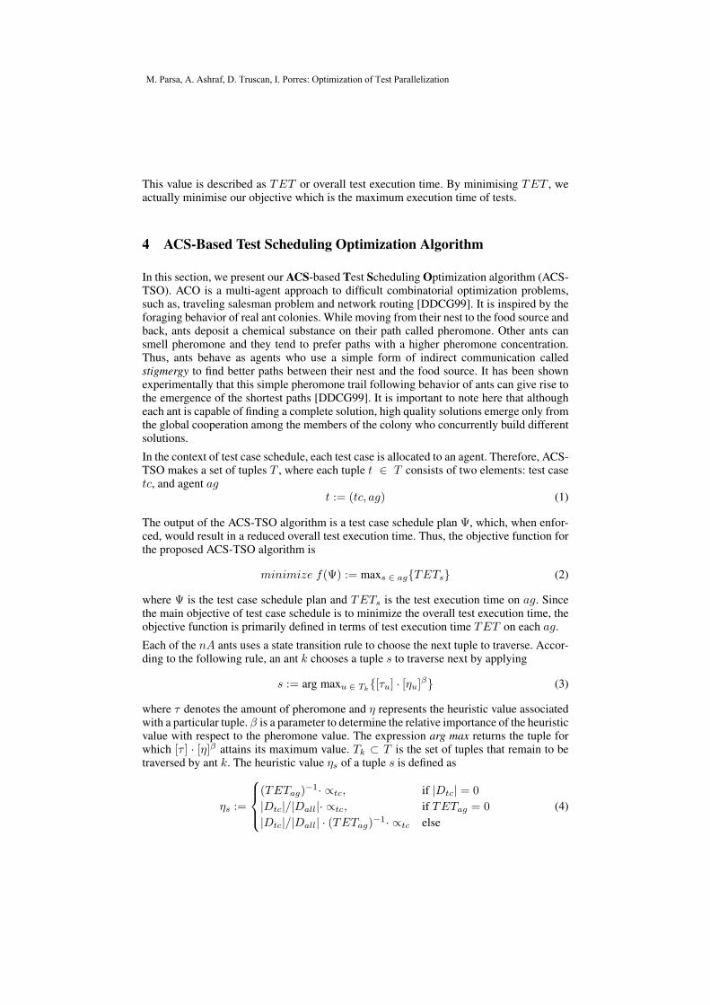
This value is described as TET or overall test execution time. By minimising TET , weactually minimise our objective which is the maximum execution time of tests.
4 ACS-Based Test Scheduling Optimization Algorithm
In this section, we present our ACS-based Test Scheduling Optimization algorithm (ACS-TSO). ACO is a multi-agent approach to difficult combinatorial optimization problems,such as, traveling salesman problem and network routing [DDCG99]. It is inspired by theforaging behavior of real ant colonies. While moving from their nest to the food source andback, ants deposit a chemical substance on their path called pheromone. Other ants cansmell pheromone and they tend to prefer paths with a higher pheromone concentration.Thus, ants behave as agents who use a simple form of indirect communication calledstigmergy to find better paths between their nest and the food source. It has been shownexperimentally that this simple pheromone trail following behavior of ants can give rise tothe emergence of the shortest paths [DDCG99]. It is important to note here that althougheach ant is capable of finding a complete solution, high quality solutions emerge only fromthe global cooperation among the members of the colony who concurrently build differentsolutions.
In the context of test case schedule, each test case is allocated to an agent. Therefore, ACS-TSO makes a set of tuples T , where each tuple t ∈ T consists of two elements: test casetc, and agent ag
t := (tc, ag) (1)
The output of the ACS-TSO algorithm is a test case schedule plan Ψ, which, when enfor-ced, would result in a reduced overall test execution time. Thus, the objective function forthe proposed ACS-TSO algorithm is
minimize f(Ψ) := maxs ∈ ag{TETs} (2)
where Ψ is the test case schedule plan and TETs is the test execution time on ag. Sincethe main objective of test case schedule is to minimize the overall test execution time, theobjective function is primarily defined in terms of test execution time TET on each ag.
Each of the nA ants uses a state transition rule to choose the next tuple to traverse. Accor-ding to the following rule, an ant k chooses a tuple s to traverse next by applying
s := arg maxu ∈ Tk{[τu] · [ηu]β} (3)
where τ denotes the amount of pheromone and η represents the heuristic value associatedwith a particular tuple. β is a parameter to determine the relative importance of the heuristicvalue with respect to the pheromone value. The expression arg max returns the tuple forwhich [τ ] · [η]β attains its maximum value. Tk ⊂ T is the set of tuples that remain to betraversed by ant k. The heuristic value ηs of a tuple s is defined as
ηs :=
(TETag)
−1· ∝tc, if |Dtc| = 0
|Dtc|/|Dall|· ∝tc, if TETag = 0
|Dtc|/|Dall| · (TETag)−1· ∝tc else(4)
M. Parsa, A. Ashraf, D. Truscan, I. Porres: Optimization of Test Parallelization
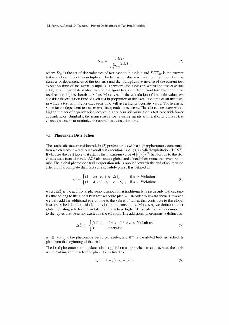
∝tc:=TETtc∑
tc ∈ TCTETtc
(5)
where Dtc is the set of dependencies of test case tc in tuple s and TETag is the currenttest execution time of ag in tuple s. The heuristic value η is based on the product of thenumber of dependencies of the test case and the multiplicative inverse of the current testexecution time of the agent in tuple s. Therefore, the tuples in which the test case hasa higher number of dependencies and the agent has a shorter current test execution timereceives the highest heuristic value. Moreover, in the calculation of heuristic value, weconsider the execution time of each test in proportion of the execution time of all the tests,in which a test with higher execution time will get a higher heuristic value. The heuristicvalue favors dependent test cases over independent test cases. Therefore, a test case with ahigher number of dependencies receives higher heuristic value than a test case with fewerdependencies. Similarly, the main reason for favoring agents with a shorter current testexecution time is to minimize the overall test execution time.
4.1 Pheromone Distribution
The stochastic state transition rule in (3) prefers tuples with a higher pheromone concentra-tion which leads in a reduced overall test execution time. (3) is called exploitation [DG97].It chooses the best tuple that attains the maximum value of [τ ] · [η]β . In addition to the sto-chastic state transition rule, ACS also uses a global and a local pheromone trail evaporationrule. The global pheromone trail evaporation rule is applied towards the end of an iterationafter all ants complete their test suite schedule plans. It is defined as
τs :=
{(1− α) · τs + α ·∆+
τs , if s /∈ Violations(1− 3 ∗ α) · τs + α ·∆+
τs , if s ∈ Violations(6)
where ∆+τs is the additional pheromone amount that traditionally is given only to those tup-
les that belong to the global best test schedule plan Ψ+ in order to reward them. However,we only add the additional pheromone to the subset of tuples that contribute to the globalbest test schedule plan and did not violate the constraints. Moreover, we define anotherglobal updating rule for the violated tuples to have higher decay pheromone in comparedto the tuples that were not existed in the solution. The additional pheromone is defined as
∆+τs :=
{f(Ψ+), if s ∈ Ψ+ ∧ s /∈ Violations0, otherwise
(7)
α ∈ (0, 1] is the pheromone decay parameter, and Ψ+ is the global best test scheduleplan from the beginning of the trial.
The local pheromone trail update rule is applied on a tuple when an ant traverses the tuplewhile making its test schedule plan. It is defined as
τs := (1− ρ) · τs + ρ · τ0 (8)
M. Parsa, A. Ashraf, D. Truscan, I. Porres: Optimization of Test Parallelization
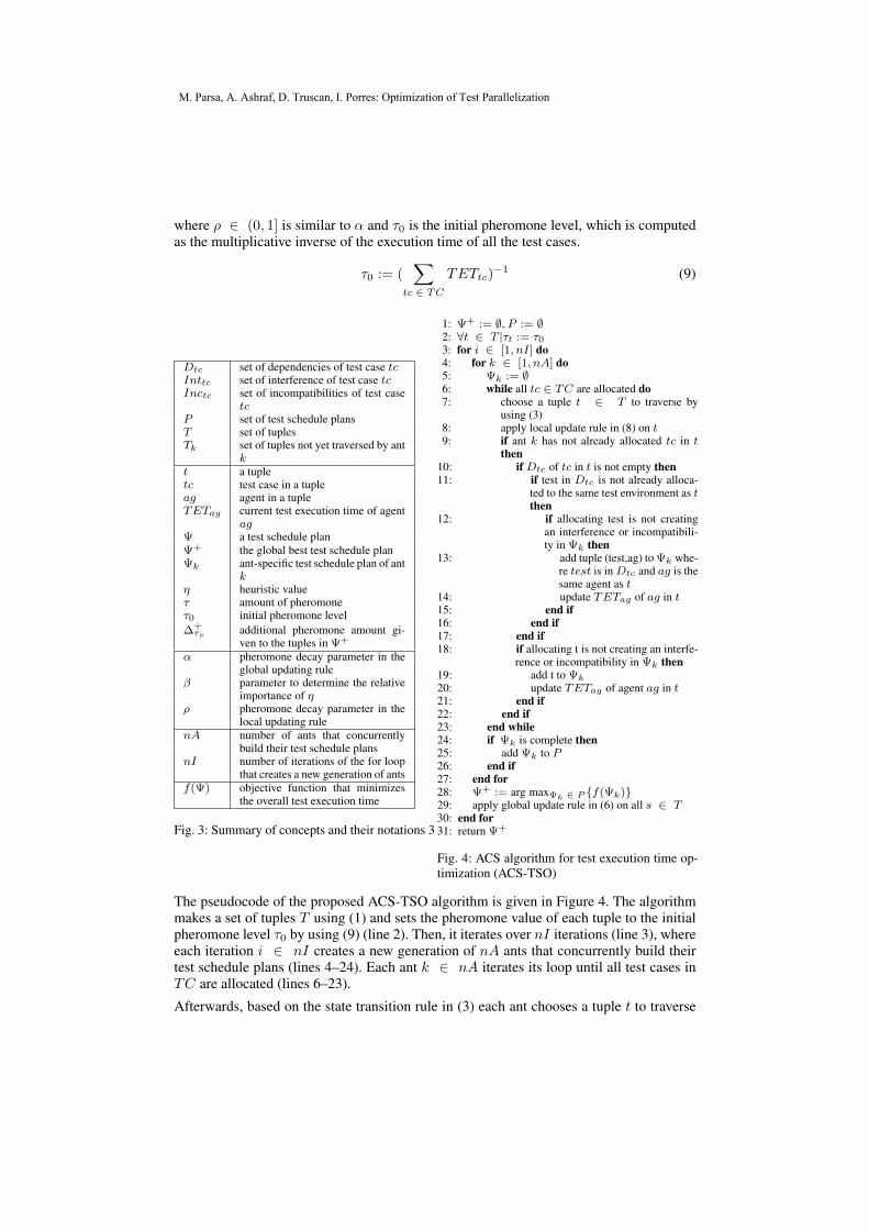
where ρ ∈ (0, 1] is similar to α and τ0 is the initial pheromone level, which is computedas the multiplicative inverse of the execution time of all the test cases.
τ0 := (∑
tc ∈ TCTETtc)
−1 (9)
Dtc set of dependencies of test case tcInttc set of interference of test case tcInctc set of incompatibilities of test case
tcP set of test schedule plansT set of tuplesTk set of tuples not yet traversed by ant
kt a tupletc test case in a tupleag agent in a tupleTETag current test execution time of agent
agΨ a test schedule planΨ+ the global best test schedule planΨk ant-specific test schedule plan of ant
kη heuristic valueτ amount of pheromoneτ0 initial pheromone level∆+τs additional pheromone amount gi-
ven to the tuples in Ψ+
α pheromone decay parameter in theglobal updating rule
β parameter to determine the relativeimportance of η
ρ pheromone decay parameter in thelocal updating rule
nA number of ants that concurrentlybuild their test schedule plans
nI number of iterations of the for loopthat creates a new generation of ants
f(Ψ) objective function that minimizesthe overall test execution time
Fig. 3: Summary of concepts and their notations 3
1: Ψ+ := ∅, P := ∅2: ∀t ∈ T |τt := τ03: for i ∈ [1, nI] do4: for k ∈ [1, nA] do5: Ψk := ∅6: while all tc ∈ TC are allocated do7: choose a tuple t ∈ T to traverse by
using (3)8: apply local update rule in (8) on t9: if ant k has not already allocated tc in t
then10: if Dtc of tc in t is not empty then11: if test in Dtc is not already alloca-
ted to the same test environment as tthen
12: if allocating test is not creatingan interference or incompatibili-ty in Ψk then
13: add tuple (test,ag) to Ψk whe-re test is inDtc and ag is thesame agent as t
14: update TETag of ag in t15: end if16: end if17: end if18: if allocating t is not creating an interfe-
rence or incompatibility in Ψk then19: add t to Ψk20: update TETag of agent ag in t21: end if22: end if23: end while24: if Ψk is complete then25: add Ψk to P26: end if27: end for28: Ψ+ := arg maxΨk ∈ P {f(Ψk)}29: apply global update rule in (6) on all s ∈ T30: end for31: return Ψ+
Fig. 4: ACS algorithm for test execution time op-timization (ACS-TSO)
The pseudocode of the proposed ACS-TSO algorithm is given in Figure 4. The algorithmmakes a set of tuples T using (1) and sets the pheromone value of each tuple to the initialpheromone level τ0 by using (9) (line 2). Then, it iterates over nI iterations (line 3), whereeach iteration i ∈ nI creates a new generation of nA ants that concurrently build theirtest schedule plans (lines 4–24). Each ant k ∈ nA iterates its loop until all test cases inTC are allocated (lines 6–23).
Afterwards, based on the state transition rule in (3) each ant chooses a tuple t to traverse
M. Parsa, A. Ashraf, D. Truscan, I. Porres: Optimization of Test Parallelization
next (line 7). The local pheromone trail update rule in (8) and (9) is applied on t (line 8).
If ant k has not already allocated tc in t and tc is an independent test case, t is added tothe ant-specific test schedule plan Ψk if it cause no incompatibility and no interference inthe solution and the test execution time of agent ag in t, TETag , is updated to reflect theimpact of the test case schedule (line 18–21). However, if tc in t is a dependent test case(line 10), it is essential to allocate all test cases on which tc is dependent on the same testenvironment before allocating tc on ag in t. Therefore, the algorithm uses the set of testcases on which tc in t is dependent denoted as Dtc from (4)(line 11–16).
However, to prevent multiple scheduling of the same test cases on the same test environ-ment, the algorithm removes any test cases from Dtc which are already allocated to ag int (line 12). Then, it adds all tuples to the ant-specific test schedule plan Ψk where tc is inDtc and ag is the same as in t (line 13). At this point, it is possible that a test case in Dtc
may be allocated to more than one server. Such a situation may arise when more than onedependent test cases are dependent on the same test case(s). (line 18–21).
Afterwards, when all ants complete their test schedule plans, all ant-specific test scheduleplans are added to the set of test schedule plans P (line 24–26), each test schedule planΨk ∈ P is evaluated by applying the objective function in (2), the thus far global best testschedule plan Ψ+ is selected (line 28), and the global pheromone trail update rule in (6)and (7) is applied on all tuples (line 29). Finally, when all iterations i ∈ nI complete, thealgorithm returns the global best test schedule plan Ψ+ (line 31).
5 Conclusions and Future Work
In this paper, we presented a novel approach for scheduling tests in parallel. The aim isto optimize the execution time of the tests in a test suite while satisfying incompatibility,dependency and interference constraints between the tests. In order to decrease the execu-tion time we are looking for the best possible partitioning of tests in a number of groupsand reordering of tests in each group to reduce the false positive and false negative testexecution results. Since computing the exact solution is impractical for a large number oftests, we proposed a metaheuristics based approach to achieve an approximate solution inpolynomial time. The time complexity of our proposed algorithm is not linear, however,the algorithm can be parallelised to accelerate the execution time. Currently, we requirethe algorithm to be run before each integration to take the possible modification of testsinto consideration. We implemented the proposed algorithm in a Java based framework.
There is a difference between scheduling the tests and the traditional resource constrainedscheduling that required us to propose a more general scheduling strategy rather than usingone of the known algorithms. There is no notion of state in performing the tasks in resourceconstrained scheduling. If a task has been performed once, it will not be necessary to beperformed again. However, in test scheduling, the state achieved on a test environment isimportant for the other tests. In this case, it is not enough that test has been executed beforeon another environment.
In the proposed approach, we defined the interference and incompatibility as hard cons-traints in which should be satisfied while the solution is constructed, and the dependencyconstraint as a soft constraint in which we aim at reducing in the next cycles. Moreover,
M. Parsa, A. Ashraf, D. Truscan, I. Porres: Optimization of Test Parallelization
we define the objective function to reduce the execution time of tests. For the future work,we may focus on incorporating SMT (Satisfiability Modulo Theories) solvers to tackle theproblem to achieve an optimal schedule.
Acknowledgements
This work was supported by the Need for Speed (N4S) Program (http://www.n4s.fi).
Literatur
[AMPW15] S. Arlt, T. Morciniec, A. Podelski und S. Wagner. If A Fails, Can B Still Succeed? In-ferring Dependencies between Test Results in Automotive System Testing. In SoftwareTesting, Verification and Validation (ICST), 2015 IEEE 8th International Conferenceon, Seiten 1–10, April 2015.
[BMDK15] J. Bell, E. Melski, M. Dattatreya und G.E. Kaiser. Vroom: Faster Build Processes forJava. Software, IEEE, 32(2):97–104, Mar 2015.
[DDCG99] Marco Dorigo, Gianni Di Caro und Luca M. Gambardella. Ant algorithms for discreteoptimization. Artif. Life, 5(2):137–172, April 1999.
[Dep] DepUnit. https://code.google.com/p/depunit/. [Online].[DG97] M. Dorigo und L.M. Gambardella. Ant colony system: a cooperative learning approach
to the traveling salesman problem. Evolutionary Computation, IEEE Transactions on,1(1):53–66, 1997.
[GSHM15] Alex Gyori, August Shi, Farah Hariri und Darko Marinov. Reliable Testing: DetectingState-polluting Tests to Prevent Test Dependency. In Proceedings of the 2015 Inter-national Symposium on Software Testing and Analysis, ISSTA 2015, Seiten 223–233,New York, NY, USA, 2015. ACM.
[HKK05] Florian Haftmann, Donald Kossmann und Er Kreutz. Efficient regression tests fordatabase applications. In In Conference on Innovative Data Systems Research (CIDR,Seiten 95–106, 2005.
[HKL05] Florian Haftmann, Donald Kossmann und Eric Lo. Parallel Execution of Test Runs forDatabase Application Systems. In Klemens Bhm, Christian S. Jensen, Laura M. Haas,Martin L. Kersten, Per-ke Larson und Beng Chin Ooi, Hrsg., VLDB, Seiten 589–600.ACM, 2005.
[HLS+13] Mark Harman, Kiran Lakhotia, Jeremy Singer, David R. White und Shin Yoo. Cloudengineering is Search Based Software Engineering too. Journal of Systems and Soft-ware, 86(9):2225 – 2241, 2013.
[HM13] S. Haidry und T. Miller. Using Dependency Structures for Prioritization of FunctionalTest Suites. Software Engineering, IEEE Transactions on, 39(2):258–275, Feb 2013.
[MGM15] Alberto Marroquin, Douglas Gonzalez und Stephane Maag. A Novel Distributed Tes-ting Approach Based on Test Cases Dependencies for Communication Protocols. InProceedings of the 2015 Conference on Research in Adaptive and Convergent Systems,RACS, Seiten 497–504, New York, NY, USA, 2015. ACM.
[YH12] S. Yoo und M. Harman. Regression Testing Minimization, Selection and Prioritization:A Survey. Softw. Test. Verif. Reliab., 22(2):67–120, Marz 2012.
[ZJW+14] Sai Zhang, Darioush Jalali, Jochen Wuttke, Kivanc Muslu, Wing Lam, Michael D.Ernst und David Notkin. Empirically Revisiting the Test Independence Assumption.In Proceedings of the 2014 International Symposium on Software Testing and Analysis,ISSTA 2014, Seiten 385–396, New York, NY, USA, 2014. ACM.
M. Parsa, A. Ashraf, D. Truscan, I. Porres: Optimization of Test Parallelization