Workshop Manual PAJERO, MONTERO - · PDF fileSunroof Fit Adjustment 47..... SUNROOF 48........
55
BODY Click on the applicable bookmark to selected the required model year.
Transcript of Workshop Manual PAJERO, MONTERO - · PDF fileSunroof Fit Adjustment 47..... SUNROOF 48........

BODY
Click on the applicable bookmark to selected the required model year.

42-1
BODYCONTENTS
HOOD 3. . . . . . . . . . . . . . . . . . . . . . . . . . . . . . . . . . . .
FENDER 5. . . . . . . . . . . . . . . . . . . . . . . . . . . . . . . . . .
FUEL FILLER DOOR 6. . . . . . . . . . . . . . . . . . . . .
WINDOW GLASS 8. . . . . . . . . . . . . . . . . . . . . . . . .
ADHESIVES 8. . . . . . . . . . . . . . . . . . . . . . . . . . . . .
SPECIAL TOOL 8. . . . . . . . . . . . . . . . . . . . . . . . .
WINDOW REPAIR 8. . . . . . . . . . . . . . . . . . . . . . .
WINDSHIELD 10. . . . . . . . . . . . . . . . . . . . . . . . . .
QUARTER WINDOW GLASS 14. . . . . . . . . . .
BACK DOOR GLASS 16. . . . . . . . . . . . . . . . . .
DOORS 18. . . . . . . . . . . . . . . . . . . . . . . . . . . . . . . . .
SERVICE SPECIFICATIONS 18. . . . . . . . . . . .
SEALANT 18. . . . . . . . . . . . . . . . . . . . . . . . . . . . .
SPECIAL TOOLS 18. . . . . . . . . . . . . . . . . . . . . .
TROUBLESHOOTING 19. . . . . . . . . . . . . . . . . .
ON-VEHICLE SERVICE 19. . . . . . . . . . . . . . . .Door Fit Adjustment 19. . . . . . . . . . . . . . . . .Door Window Glass Adjustment 19. . . . . .Defective Power Window Adjustment andReplacement 20. . . . . . . . . . . . . . . . . . . . . . . . .Power Window Safety Mechanism Check 20. .
Door Outside Handle Play Check 21. . . . .Power Window Operation CurrentCheck 21. . . . . . . . . . . . . . . . . . . . . . . . . . . . . .Circuit Breaker (Incorporated in the PowerWindow Motor) Check 21. . . . . . . . . . . . . . .Door Inside Handle Play Check andAdjustment 21. . . . . . . . . . . . . . . . . . . . . . . . . .
DOOR ASSEMBLY 22. . . . . . . . . . . . . . . . . . . . .
DOOR TRIM AND WATERPROOFFILM 24. . . . . . . . . . . . . . . . . . . . . . . . . . . . . . . . . .
DOOR GLASS AND REGULATOR 30. . . . . .
DOOR HANDLE AND LATCH 33. . . . . . . . . .
WINDOW GLASS RUNCHANNEL ANDDOOR OPENING WEATHERSTRIP 36. . . . .
BACK DOOR 39. . . . . . . . . . . . . . . . . . . . . . . . . . .
SERVICE SPECIFICATION 39. . . . . . . . . . . . .
SEALANT 39. . . . . . . . . . . . . . . . . . . . . . . . . . . . .
SPECIAL TOOL 39. . . . . . . . . . . . . . . . . . . . . . .
TROUBLESHOOTING 39. . . . . . . . . . . . . . . . . .
CONTINUED ON NEXT PAGE

42-2
ON-VEHICLE SERVICE 40. . . . . . . . . . . . . . . .Back Door Fit Adjustment 40. . . . . . . . . . . .Back Door Handle Play Check 40. . . . . . .
BACK DOOR ASSEMBLY 41. . . . . . . . . . . . . .
BACK DOOR TRIM AND WATERPROOFFILM 43. . . . . . . . . . . . . . . . . . . . . . . . . . . . . . . . . .
BACK DOOR HANDLE AND LATCH 44. . . .
KEYLESS ENTRY SYSTEM 45. . . . . . . . . . . . .
TROUBLESHOOTING 45. . . . . . . . . . . . . . . . . .
ON-VEHICLE SERVICE 45. . . . . . . . . . . . . . . . .How to Replace a Battery of theTransmitter 45. . . . . . . . . . . . . . . . . . . . . . . . . .
Encrypted Code Registration Method 45. .
KEYLESS ENTRY SYSTEM 46. . . . . . . . . . . .
SUNROOF 47. . . . . . . . . . . . . . . . . . . . . . . . . . . . . .
SERVICE SPECIFICATION 47. . . . . . . . . . . . .
TROUBLESHOOTING 47. . . . . . . . . . . . . . . . . .
ON-VEHICLE SERVICE 47. . . . . . . . . . . . . . . .Water Test 47. . . . . . . . . . . . . . . . . . . . . . . . . .Sunroof Fit Adjustment 47. . . . . . . . . . . . . . .
SUNROOF 48. . . . . . . . . . . . . . . . . . . . . . . . . . . .

BODY - Hood 42-3
HOODREMOVAL AND INSTALLATION
2
5.0 ± 1.0 N×m
2
4
5
97
1
8
22 ± 4 N×m
6
9.0 ± 2.0 N×m
3
7
1
7
7
5
Hood latch removal stepsD Front grille (Refer to GROUP 51.)1. Hood latchHood lock release cable removalsteps2. Hood lock release handle3. Hood lock release cableHood removal steps4. Hood silencer
5. Hood weatherstripD Washer hose(Refer to GROUP 51.)
6. Hood7. Hood bumper8. Hood support rod
(Refer to GROUP 51.)9. Hood support rod
(Refer to GROUP 51.)

BODY - Hood42-4
A
6
4
A
6
4
AA
B
B
6
7
6
7
15 ± 0.5 mm
20 ± 0.5mm
Adjustment of hood stepand hood striker linkage
Adjustment of clearance aroundhood
Adjustment of hood height
Section A - A Section B - B
: Clip positions
Clip positions
Clip
Section A - A
W0382AL

BODY - Fender 42-5
FENDERREMOVAL AND INSTALLATION
Caution: SRSDo not strike the front impact sensor when removing or installing the fender.
Pre-removal and Post-installation OperationD Front Bumper Removal and Installation
(Refer to GROUP 51.)D Front Mud Guard Removal and Installation
(Refer to GROUP 51.)
D Overfender Removal and Installation(Refer to GROUP 51.)
32
1
3
1A
A
Section A � A
Clip
Removal steps1. Splash shield
AA" "AA 2. Side turn signal lamp3. Fender
REMOVAL SERVICE POINTAA"SIDE TURN SIGNAL LAMP REMOVALUse the special tool to unhook the fender, and then removethe side turn-signal lamp.
MB990784Side turnsignal lamp
Front of vehicle

BODY - Fender/Fuel Filler Door42-6
INSTALLATION SERVICE POINT"AASIDE TURN SIGNAL LAMP INSTALLATIONEngage the hook into the fender panel, and then install theside turn signal lamp.
FUEL FILLER DOOR
REMOVAL AND INSTALLATION
Pre-removal and Post-installation OperationsD Quarter Trim, Lower (R.H.) Removal and Installation
(Refer to GROUP 52A.)D Center Pillar Trim, Lower (Long Wheelbase - R.H.)
Removal and Installation (Refer to GROUP 52A.)
5
21
3
4
3
Removal stepsAA" "AA 1. Rivet
2. Fuel filler door panel assembly3. Fuel filler door lock hook assembly4. Lid lock release handleD Heater deck cross assembly(Refer to GROUP 55.)
D AC inverter (Long wheelbase)(Refer to GROUP 54.)
5. Fuel filler door lock release cable
Hook
Fender panel
Front of vehicle

BODY - Fuel Filler Door 42-7
REMOVAL SERVICE POINTAA"RIVET REMOVALUse a drill (Ø6.5 - 7.5 mm) to break the rivet by drillinga hole, and then remove the rivet.
INSTALLATION SERVICE POINT"AARIVET INSTALLATIONUse a riveter shown to install rivets as follows:1. Insert a rivet in the body panel and fuel filler door panel
assembly.2. Insert the riveter to the rod (A shown) of a rivet.3. Pressing the flange surface of the rivet with the riveter,
handle the riveter.4. The rod is cut at its thinnest point and the rivet is held
in position.
Drill
Fuel fillerdoor panelassembly
Rivet
Riveter
Fuel filler doorpanel assemblyBody
panel A
Rivet
Riveter
Flange surface
Rivet
1
2
3
4

BODY - Window Glass42-8
WINDOW GLASSADHESIVE
Items Specified adhesive
Windshield 3M ATD Part No. 8609 Super Fast Urethane Auto Glass
Quarter window glassSealant or equivalent
Back door glass
Quarter window garnish 3M ATD Part No. 8513 Grommeted Windshield Sealantor equivalent
SPECIAL TOOL
Tool Number Name Use
MB990480 Window glassholder
Removal and installation of windshield
WINDOW REPAIRThe following glass parts are installed with a liquid urethaneadhesive method:D WindshieldD Quarter window glassD Back door window glass
ITEMS NEEDED
Name Remarks
Adhesive 3M ATD Part No. 8609 Super Fast Urethane Auto Glass Sealant orequivalent
Primer 3M ATD Part No. 8608 Super Fast Urethane Primer or equivalent
Spacers Available as service part
Dam Available as service part
Anti-rust solvent (or Tectyl 506T...Valvoline OilCompany)
For rust prevention
Isopropyl alcohol For grease removal from bonded surface
Steel piano wire Dia.× length...0.6mm× 1m For cutting adhesive
Adhesive gun For pressing-out adhesive

BODY - Window Glass 42-9
HANDLING OF AUTO WINDOW SEALERKeep the sealant in a cool place, not exposed to the directrays of the sun. Do not place any heavy article on the sealantnor press it, otherwise it will become deformed. Avoid storingthe sealant for more than 6 months, because it will lose itssealing effect.BODY PINCH-WELD FLANGE SERVICINGBefore servicing the body pinch-weld flange, remove oldadhesive completely. If the flange requires painting, bakeit after painting is completed.
WORKING PROCESSWindow glass installation procedure
Body side
Cleaning of adhesion surfaceCut off the residual adhesive until thethickness is less than 2 mm. Clean theadhesion surface with isopropyl alcohol,and let dry for 3 minutes or more.
Attaching of clip, spacer and duallock fastenerAttach the clip, spacer and dual lockfastener to set the positions for theglassto be installed.
Application of primerApply to the adhesion surface of thebody and let dry for 3 minutes or more.
Window glass side
Reusing the glass Replacing the glass
Cleaning of adhesion surfaceCompletely cut off all of the residualadhesive. Clean the adhesionsurface with isopropyl alcohol, andlet dry for 3 minutes or more.
Cleaning of adhesion surfaceClean off any dirt adhering to the adhe-sion surface with isopropyl alcohol, andlet dry for 3 minutes or more.
Gluing of window spacer, glass stoppers and dual lock fastenerGlue the window spacer, glass stoppers and dual lock fastener along the standard positionon the glass outer circumference.
Application of primerApply sufficient primer evenly to the adhesion surface so that there is no patchiness. Afterapplication, let dry for 3 to 30 minutes.
Application of adhesiveWithin 30 minutes after applying the primer, apply the adhesive evenly all the way aroundthe inside edge of the glass.
Installing the glassAfter applying the adhesive, lightly press the glass evenly so that it adherescompletely.
CleaningAfter removing any adhesive that is sticking out or adhering to the body orglass with a spatula, etc., clean off with isopropyl alcohol.
Checking for water leaksCarry out a shower test to check that no water will leak through.

BODY - Window Glass42-10
WINDSHIELDREMOVAL AND INSTALLATION
Pre-removal and Post-installation OperationsD Deck Garnish Removal and Installation
(Refer to GROUP 51A.)D Headlining Removal and Installation
D Front Pillar Trim Removal and Installation(Refer to GROUP 52A � Trim.)
Unit: mm
1
B B
A
A
C
C
8
2
2
4
5
3
10
32.5
8
Primer Primer
Primer
Adhesive: 3M ATD Part No. 8609 Super Fast Urethane Auto Glass Sealant or equivalent
Section A � A Section B � B Section C � C
Removal steps1. Wiper deicer connector (Refer to
GROUP 51.)AA" "AA 2. Windshield
"AA 3. Windshield moulding"AA 4. Windshield spacer"AA 5. Glass stopper

BODY - Window Glass 42-11
REMOVAL SERVICE POINTAA"WINDSHIELD REMOVAL1. In order to protect the body (paint surface), apply cloth
tape to all body areas around the installed windshield.2. Using a sharp-point drill, make hole in the windshield
adhesive.3. Pass the piano wire from the inside of the vehicle through
the hole.4. Pull the piano wire alternately from the inside and outside
along the windshield to cut the adhesive.
CautionDo not let the piano wire touch the edge of thewindshield.
5. Make alignment marks on the windshield and body.6. Use the special tool to remove the windshield.
7. Use a knife to cut away remaining adhesive to 2 mmthick or less around the entire circumference of the bodyflange.
8. Smooth the flange surface.
Caution(1) Use care not to remove more adhesive than
necessary, or the adhesive could weaken.(2) Be careful also not to damage the paintwork on
the body surface with the knife. If the paintworkis damaged, repair the damaged area with repairpaint or anti-rust agent.
9. When reusing windshield, remove the remaining adhesiveon the windshield completely. Then, decrease thewindshield with isopropyl alcohol.
10. Decrease the body flange in the same way.
CautionBefore the next job, leave the decreased parts for3 minutes or more to dry. Also, do not touch anycleaned surface.
MB990480

BODY - Window Glass42-12
INSTALLATION SERVICE POINT"AAGLASS STOPPER/WINDSHIELD MOULDING/WINDSHIELD SPACER/WINDSHIELD
INSTALLATION1. When replacing the windshield, first align it with the body, and then matchmark them.2. Use isopropyl alcohol to clean the inside edge of the windshield and the body flange.3. Use a primer dampened sponge to apply the clear gasoline to the specified area around the windshield
and the body evenly.4. After the application, let it dry for at least three minutes.5. Position the glass stopper and the windshield spacer as shown, ensuring that there are no bends
or warpages inside the windshield.Glass stopper and spacer installation position
Ceramic line
22.5mm
Windshield
Glass end line
Ceramic line
Glass stopper
Align the glassstopper end withthe ceramicnotch.
Glass end line
Windshield spacer
13.2mm
21.5mm
Caution(1) The primer strengthens the adhesive, so be sure to apply it evenly around the entire
circumference. However, a too thick application will weaken the adhesive.(2) Never touch the primer-applied surface.
6. Align the marking on the windshield moulding with thewindshield notch, and then install the windshieldmoulding.
Windshield
Marking
Ceramic line
Notch
Windshield moulding

BODY - Window Glass 42-13
7. Within thirty minutes after the primer application, fill asealant gun with adhesive, and then apply the adhesiveevenly around the windshield.
NOTECut the tip of the sealant gun nozzle into a V shapeto simplify adhesive application.
8. Align the mating marks on the windshield and the body,and lightly press the windshield evenly so that it adherescompletely.
9. Use a spatula or the like to remove any excessiveadhesive. Install the windshield moulding before theadhesive sets. After the windshield is installed, wait untilthe adhesive sets.(Refer to P.42-9.)
10. Wait thirty minutes or more, and then test for waterleakage.
Caution(1) Do not move the vehicle unless absolutely
necessary.(2) When testing for water leakage, do not pinch the
end of the hose to spray the water.
10 mm
15 mm

BODY - Window Glass42-14
QUARTER WINDOW GLASSREMOVAL AND INSTALLATION
Pre-removal and Post-installation OperationQuarter Trim, Upper Removal and Installation(Refer to GROUP 52A.)
1
9
2
1
2
33
6
45
3
6
78
<Short wheelbase> <Long wheelbase>
Section A � A
Primer
Clip
A
A
Body panel
8
59
Adhesive: 3MATDPartNo. 8513GrommetedWindshield Sealant or equivalent
Removal steps1. Lever2. Quarter window link3. Rubber and nut4. Quarter window glass
AA" 5. Quarter window glass
6. Quarter window weatherstrip7. Quarter window hinge
AA" "AA 8. Quarter window moulding9. Quarter window garnish

BODY - Window Glass 42-15
REMOVAL SERVICE POINTAA"QUARTER WINDOW GLASS/QUARTER WINDOW
MOULDING REMOVALRemove by the same procedure as for the windshield. (Referto P.42-11.)
INSTALLATION SERVICE POINT"AAQUARTER WINDOW MOULDING INSTALLATION1. Wipe away all adhesive which is adhering to the channel
in the quarter window moulding and to the quarter windowglass, and then clean the surfaces with unleaded petrol.
CautionThe areas which have been cleaned of adhesiveshould be allowed to stand for three minutes or moreuntil they are completely dry before continuing tothe next step. Furthermore, do not touch the surfacesafter they have been cleaned.
2. Apply an even coating of primer to the adhesion surfaceof the quarter window glass, while being careful not tomiss any places.
3. Apply the specified sealant to the quarter window glassin the locations specified, and then install the quarterwindow moulding to the quarter window glass.
Adhesive:3M ATD part No.8513 Grommeted Sealant orequivalent
Quarter windowglass
Quarter window glass
8.5 mm
15 mm
15 mm
Adhesive: 3M ATD Part No. 8513Grommeted Windshield Sealant orequivalent

BODY - Window Glass42-16
BACK DOOR GLASSREMOVAL AND INSTALLATION
Pre-removal and Post-installation OperationsD Back Door Upper Trim Removal and Installation
(Refer to P.42-43.)D Spare Tire Removal and Installation
Unit: mm
2
1
4
3
3
5
Section A � A Section B � B Section C � C Section D � D
1
A
A
B B C
C
D
D
12.5
12.5
13 12.5
18 24.5
Adhesive: 3M ATD Part No. 8609 Super Fast Urethane Auto Glass Sealant or equivalent
Primer
Primer
Primer
Primer
Removal steps1. Harness connector
AA" "AA 2. Back door glass"AA 3. Dual lock fastener
"AA 4. Glass stopper"AA 5. Window dam
REMOVAL SERVICE POINTAA"BACK DOOR GLASS REMOVALRemove the back door glass in the same manner as forthe windshield. (Refer to P42-11.)

BODY - Window Glass 42-17
INSTALLATION SERVICE POINT"AAWINDOW DAM/GLASS STOPPER/DUAL LOCK FASTENER/BACK DOOR GLASS
INSTALLATION1. Clean both the glass side and vehicle body side of the window dam, dual lock fastener and glass
stopper mounting surfaces with unleaded petrol.2. Install the window dam.
Section A � A
Window dam
Back door glass
Align the back doorglass end with thewindow dam end.
Window dam installation positionA
A
Align withedge of glass
AA
3. Attach the dual lock fastener to the body flange in thecorrect position.
4. Attach the dual lock fastener and glass stopper to theback door window glass in the positions which correspondto the dual lock fastener and glass stopper mountingsections of the body flange.
5. Apply the primer and adhesive.6. Install the glass by the same procedure as for the
windshield. (Refer to P.42-12.)Raised section ofbody flange
Dual lock fastener
Glass stopperinstallation holes

BODY - Doors42-18
DOORSSERVICE SPECIFICATIONS
Items Standard value
Door outside handle play mm 2.0 or more
Power window operating current A 5.0 ± 2 (power supply 14.5 ± 0.3 V at 23_C)
Door inside handle play mm 5.3 or more
SEALANT
Items Specified sealant Remark
Waterproof film 3M ATD Part No. 8625 or equivalent Ribbon sealer
SPECIAL TOOLS
Tool Number Name Use
MB990784 Ornament remover Door trim removal
MB990900 orMB991164
Door hinge adjust-ing wrench
Adjustment of door fit
A
B
C
D
MB991223A: MB991219B: MB991220C: MB991221D: MB991222
Harness setA: Test harnessB: LED harnessC: LED harness
adapterD: Probe
Terminal voltage measurementA: Connector pin contact pressure checkB: Power circuit checkC: Power circuit checkD: Commercial tester connection

BODY - DoorsBODY - Doors 42-19
TROUBLESHOOTINGDIAGNOSIS FUNCTIONThe power window and central door locking is controlled by the Smart Wiring System (SWS). Fortroubleshooting, refer to GROUP 54B - Troubleshooting.
ON-VEHICLE SERVICEDOOR FIT ADJUSTMENT1. If clearance between the door and body is uneven, affix
protective tape to the fender around the hinge and tothe edge of the door. Then use the special tool to loosenthe door hinge mounting bolts on the body, and adjustthe clearance around the door so that it becomes even.
2. If the door and body are not flush with each other, usethe special tool to loosen the door hinge mounting boltson the door. Then align the door.
CautionDo not load more than 98 N×m on the special tool.
3. If the door opening and closing is heavy, adjust themeshing of the striker and the door latch (forward andbackward) by adding shims to the striker and by movingthe striker up and down or to the left and right.
DOOR WINDOW GLASS ADJUSTMENTCheck that the door glass operates smoothly and movesalong the door glass runchannel when the door window glassis fully raised and fully lowered. If there is a problem, adjustby the following procedure.1. Remove the door trim and waterproof film. (Refer to
P.42-24.)
MB990900 orMB991164
Striker Shim

BODY - Doors42-20
2. With the door window glass fully closed, loosen the doorglass mounting screws through the adjusting holes, andthen lower the door window glass slightly.
3. Fully close the door window glass again, and then fullytighten the door glass mounting screws through theadjusting holes.
DEFECTIVE POWER WINDOW ADJUSTMENTAND REPLACEMENTIf the window glass wrongly, automatically lowers while beingraised, adjust or replace as follows:1. Remove the door trim and the waterproof film. (Refer
to P.42-24.)2. Remove the window regulator assembly from the door
window glass, and then raise and lower the door windowglass by hand to check the operation force.
NOTEInsert soft stuff like cushion to prevent damage to theglass if it falls down.
3. If the door window glass does not move up and downsmoothly, do as follows:D Check the installation condition of the runchannel.D Straighten twist in the door sash.D Check the installation condition of the lower sash
or the center sash.
NOTEThe lower sash cannot normally be adjusted, but it maybe possible to adjust the sash span slightly within therange allowed by manufacturing tolerances by pushingthe lower sash outwards while re-installing it.
4. If repair or adjustment is impossible, replace the doorassembly.
POWER WINDOW SAFETY MECHANISMCHECK1. Place a wooden board about 10 mm thick as shown.
Then, raise the window glass.2. Check that the window lowers by about 150 mm when
the window clamps the board. If this doesn�t happen,do troubleshooting. (Refer to P.42-19.)
Front Rear
Adjustinghole
Adjustinghole
RunchannelDoorsash
Lower sash

BODY - Doors 42-21
DOOR OUTSIDE HANDLE PLAY CHECK1. Check that the door outer handle play is at the standard
value.
Standard value (A):Front 2.0 mm or less
Rear 1.7 mm or less
2. Check the door outside handle and door latch assembly,and replace the assembly if there is a malfunction.
POWER WINDOW OPERATION CURRENTCHECK1. Remove the power window fuse, and connect amultimeter
as shown in the illustration.2. When the power window switch is pressed to the UP
side, a large amount of operating current flows whenthe window starts and stops moving, so measure thecurrent during the period between these two extremes.
Standard value:5.0 ± 2 A (Power supply voltage 14.5 ± 0.3 V,at 23°C)
3. If the current is outside the standard value, refer toTroubleshooting (Refer to P.42-19.)
CIRCUIT BREAKER (INCORPORATED IN THEPOWER WINDOW MOTOR) CHECK1. Turn the power window switch to UP to close the window
glass. Keep the switch at the fully-closed position foranother 10 seconds.
2. Release the power window switch and immediately turnit to DOWN. Under this condition if the window glassstarts to lower within 60 seconds, the circuit breaker canbe judged good.
DOOR INSIDE HANDLE PLAY CHECK ANDADJUSTMENT1. Check that the door inside handle play is at the standard
value.
Standard value (A): 5.3 mm or less
2. If the play is outside the standard value, remove thedoor trim. (Refer to P.42-24.)
3. Adjust the door inside handle play by using the clip whichconnects the door inside handle and the rod.
A
A
Section B - B
B B

BODY - Doors42-22
DOOR ASSEMBLYREMOVAL AND INSTALLATION
Post-installation OperationDoor Fit Adjustment (Refer to P.42-19.)
FRONT DOOR
21 ± 4 N×m
4, 5
3
5
1
4
2
6
7
89
11 ± 2 N×m
26 ± 4 N×m
Door assembly removal steps1. Harness connector2. Door check connecting bolt3. Door assembly4. Door upper hinge5. Door lower hinge
Striker removal steps6. Striker7. Striker shimDoor switch removal steps8. Door switch cap9. Door switch

BODY - Doors 42-23
REAR DOOR
21 ± 4 N×m
4, 5
5
1
4
2
6
7
9
3
8
26 ± 4 N×m
11 ± 2 N×m
Door assembly removal steps1. Harness connector2. Door check connecting bolt3. Door assembly4. Door upper hinge5. Door lower hinge
Striker removal steps6. Striker7. Striker shimDoor switch removal steps8. Door switch cap9. Door switch
INSPECTIONDOOR SWITCH CONTINUITY CHECK
Switch position Terminal number1 2 3
Released (ON)Depressed (OFF)

BODY - Doors42-24
DOOR TRIM AND WATERPROOF FILMREMOVAL AND INSTALLATIONFRONT DOOR
12
3
4
56
78
910
11
12
13
14
15
16
17
18
19
4.9±1.0 N×m
Sealant:3M ATD Part No. 8625 or equivalent
20
21
22
22
Removal stepsAA" 1. Power window switch and power
window switch panel assembly2. Power window switch panel3. Power window switch4. Delta cover, inner5. Door lamp assembly
AB" "BA 6. Clip <Vehicles without power win-dows>
"BA 7. Escutcheon <Vehicles without pow-er windows>
"BA 8. Regulator handle <Vehicles withoutpower windows>
9. Door inside handle cover and doortrim assembly
10. Door belt line moulding assembly11. Door trim12. Front arm restraint cover
AC" 13. Door inside handle cover14. Door grip15. Grip bracket16. Door grip upper retainer17. Door grip lower bracket18. Arm restraint bracket19. Speaker20. Power window switch bracket21. Door inside handle
"AA 22. Waterproof film

BODY - Doors 42-25
REAR DOOR
21
12
4
3
56
7
8
10
11
12
13
14
15
916
17
18
4.9±1.0 N×m
19
20
21
Sealant:3M ATD Part No. 8625 or equivalent
Removal stepsAA" 1. Power window switch and power
window switch panel assembly2. Power window switch panel3. Power window switch4. Door lamp assembly
AB" "BA 5. Clip <Vehicles without power win-dows>
"BA 6. Escutcheon <Vehicles without pow-er windows>
"BA 7. Regulator handle <Vehicles withoutpower windows>
8. Door inside handle cover9. Door belt line moulding assembly
10. Door trimAC" 11. Door inside handle cover
12. Door grip13. Rear arm restraint cover14. Door grip bracket15. Door grip upper retainer16. Door grip lower bracket17. Arm restraint bracket18. Speaker19. Power window switch bracket20. Door inside handle
"AA 21. Waterproof film

BODY - Doors42-26
CLIP AND CLAW POSITIONS
A
AA
A
B
B
B
C
C E
E
E
EDD
D D
D D
DD
FRONT DOOR
<Short wheelbase>
<Long wheelbase>
B
Door lamplens
Door lamplens cover
Door trim
Claw
ClipDoor trim
Clip
Door trim
Clip
Door trim
Power window switch panel assembly Power window switch panel assembly
Door lamp lens
Power window switch panel assembly
Power window switch panel assembly
View A
View B
View C
Section A - A
Front arm restraint cover
View A
View A View B View C
Section B - B Section C - C
Section D - D Section E - E
: Claws positions: Clips positions
NOTE

BODY - Doors 42-27
D D
C
C E
E
A
A
B
B
REAR DOOR
View A
View B
View A View B Section A - A
Section B - B Section C - C Section D - D Section E - E
Power window switch panel assemblyFront arm restraint cover
Clip
Claw
Door trim
Door lamp lens
Clip
Door trim
Power window switch panelassembly
Power window switchpanel assemblyDoor lamp
lens
Door lamplens cover
Door trim
Door trim
Clip
: Claws positions: Clips positions
NOTE

BODY - Doors42-28
REMOVAL SERVICE POINTSAA"POWER WINDOW SWITCH AND POWER
WINDOW SWITCH PANEL ASSEMBLY REMOVALUse the special tool to twist the front and rear of the powerwindow switch and panel assembly to remove it. (Refer toP.42-26, 27, Clip and claw positions.)
AB"CLIP REMOVALUse a cloth to remove the clip as shown in theillustration.
AC"DOOR INSIDE HANDLE COVER REMOVAL1. Insert the special tool between the inside handle upper
part and the inside handle cover, and then disengagethe upper claw of the inside handle.
2. Disengage the lower claw of the inside handle in thesame manner as for the upper claw.
3. Remove the door trim.4. Remove the inside handle cover from the door trim.
MB990784
MB990784
A
A
Claw
Inside handle
Inside handlecover
Insidehandlecover
Insidehandle
Claw
Section A - A
BODY - Doors 42-29
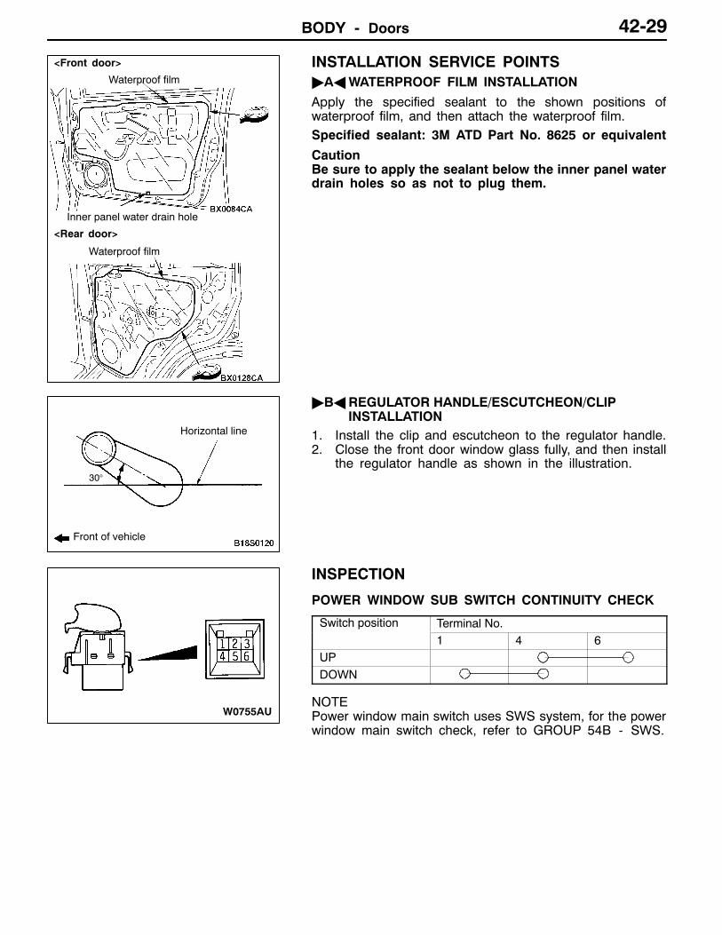
INSTALLATION SERVICE POINTS"AAWATERPROOF FILM INSTALLATION
Apply the specified sealant to the shown positions ofwaterproof film, and then attach the waterproof film.Specified sealant: 3M ATD Part No. 8625 or equivalent
CautionBe sure to apply the sealant below the inner panel waterdrain holes so as not to plug them.
"BAREGULATOR HANDLE/ESCUTCHEON/CLIPINSTALLATION
1. Install the clip and escutcheon to the regulator handle.2. Close the front door window glass fully, and then install
the regulator handle as shown in the illustration.
INSPECTION
POWER WINDOW SUB SWITCH CONTINUITY CHECK
Switch position Terminal No.1 4 6
UPDOWN
NOTEPower window main switch uses SWS system, for the powerwindow main switch check, refer to GROUP 54B - SWS.
Waterproof film
<Front door>
<Rear door>
Waterproof film
Inner panel water drain hole
Front of vehicle
30°
Horizontal line
W0755AU

BODY - Doors42-30
DOOR GLASS AND REGULATORREMOVAL AND INSTALLATIONFRONT DOOR
Pre-removal OperationDoor Trim and Waterproof Film Removal(Refer to P.42-24.)
Post-installation OperationD Door Window Glass Adjustment (Refer to P.42-20.)D Door Trim and Waterproof Film Installation (Refer
to P.42-24.)
65
2
13
4
5.4±0.5 N×m
7
5.4±0.5 N×m
7
<Vehicles with power windows>
<Vehicles without power windows>
Door window glass removal steps1. Door belt line moulding assembly2. Door window glass runchannel
"BA D Check operation3. Door window glass4. Glass holder
Power window regulator and motorassembly removal steps5. Power window regulator and motor
assembly"AA 6. Power window motor assembly"AA 7. Power window regulator assembly

BODY - Doors 42-31
REAR DOOR
Pre-removal OperationDoor Trim and Waterproof Film Removal (Refer toP.42-25.)
Post-installation OperationD Door Window Glass Adjustment (Refer to P.42-20.)D Door Trim and Waterproof Film Installation (Refer
to P.42-25.)
1
2
3
4 56
7
8
9
10
5.4±0.5 N×m8
5.4±0.5 N×m<Vehicles without power windows>
<Vehicles with power windows>
Removal steps1. Door belt line moulding assembly2. Door window glass runchannel
AA" "CA 3. Center sash"BA D Check operation
4. Rear door window glass5. Glass holder
6. Power window regulator and motorassembly
"AA 7. Power window motor assembly"AA 8. Power window regulator assembly
9. Stationary window glass10. Stationary window weatherstrip
REMOVAL SERVICE POINTAA"CENTER SASH REMOVAL1. Remove only the section of the door outer opening
weatherstrip which is attached to the center sash.2. Remove the center sash mounting screws, and then
remove the center sash from the door panel.Door outeropening weather-strip
Center sash

BODY - Doors42-32
INSTALLATION SERVICE POINTS"AAPOWER WINDOW MOTOR ASSEMBLY/POWER
WINDOW REGULATOR ASSEMBLYINSTALLATION
Power window motor assembly and window regulatorassembly pre-installation operations1. Connect the power window motor assembly to the body
side harness connector, and then turn the ignition switchON.
2. Operate the power window motor assembly for 5-10seconds by pressing the power window switch to theUP position.
NOTEThis operation will cause the limit switch inside the powerwindow motor assembly to be reset.
Caution(1) The power window motor assembly should not
be operated again until it is installed to the glass.(2) The clamping prevention function does not
operate the first time that the glass is fully closed."BACHECK OPERATION1. Install the glass to the power window motor assembly.2. Press the power window switch to fully-close the glass,
and then return the glass to the fully-open position.
NOTEThis operation will program the power window-ECU.
"CACENTER SASH INSTALLATIONSecurely insert the center sash into the window rear sash(door).
INSPECTIONPOWER WINDOW RELAY CONTINUITY CHECK
Battery voltage Terminal No.1 3 4 5
Not appliedApplied
Power window relay

BODY - Doors 42-33
DOOR HANDLE AND LATCHREMOVAL AND INSTALLATION
Pre-removal OperationDoor Trim Removal (Refer to P.42-27.)
Post-installation OperationD Door Inside Handle Play Check (Refer to P.42-21.)D Door Outside Handle Play Check (Refer toP.42-21.)D Door Trim Installation (Refer to P.42-24.)
2
5.9±1.0 N×m
1
5
3
4
6
FRONT DOOR REAR DOOR
71
2
5
5.9±1.0 N×m
6
7
Door handle and door latchassembly removal steps
"CA 1. Door inside handleD Waterproof film (Refer to P.42-24.)2. Door outside handle3. Door lock key cylinder
"BA 4. Rear lower sash
5. Door latch assembly6. Link assembly
Door check removal stepsD Waterproof film (Refer to P.42-24.)
"AA 7. Door check
INSTALLATION SERVICE POINTS"AADOOR CHECK INSTALLATIONInstall with the following identification marks upward.
Items Identification mark
Front door Left door 20L
Right door 20R
Rear door Left door 26L
Right door 26R
"BAREAR LOWER SASH INSTALLATIONBe sure to install the rear lower sash to the window rearsash (at door) securely.
Identification mark

BODY - Doors42-34
"CADOOR INSIDE HANDLE INSTALLATION1. Install the inside lock cable to the door inside handle
as follows:(1) Install the inner cable end in the inside lock cable
to the clip in the door inside handle.(2) Turn the inside lock knob to the door lock position.(3) Install the outer cable end to the door inside handle
securely.(4) Install the clip to the inner cable.
2. Install the inside handle rod to the door inside handle.3. Install the door inside handle to the door.
INSPECTIONDOOR LOCK ACTUATOR CHECKFront door<Left side>
Rod position Terminal No. Rod operation
1 2 3 4 6 Rod operation
LOCK LOCK to UNLOCK
UNLOCK UNLOCK to LOCK
LOCK*
UNLOCK*
NOTE :*: driver�s side only
<Right side>Rod position Terminal No. Rod operation
1 2 3 4 6 Rod operation
LOCK LOCK to UNLOCK
UNLOCK UNLOCK to LOCK
LOCK*
UNLOCK*
NOTE :*: driver�s side only
Outercable end
Inner cable
Left side
Clip
Door inside handle
Inside handle rod
<Left side>
View A Unlock
<Right side>
View B Unlock Lock
A
B
Lock
<Front door>

BODY - Doors 42-35
Rear door<Left side>
Rod position Terminal No. Rod operation2 3
LOCK LOCK to UNLOCKUNLOCK UNLOCK to LOCK
<Right side>
Rod position Terminal No. Rod operation2 3
LOCK LOCK to UNLOCKUNLOCK UNLOCK to LOCK
<Rear door>
B
A
<Left side>
View A
Lock
Unlock
<Right side>
View B
Unlock
Lock

BODY - Doors42-36
WINDOW GLASS RUNCHANNEL AND DOOR OPENINGWEATHERSTRIPREMOVAL AND INSTALLATION
5
3
2
1
4
6
3FRONT DOOR
Long wheelbase
Short wheelbase
3 3
Sectional view ofclip position
ClipClip
Sectional view ofclip position
Door inner opening weatherstripremoval steps
"BA 1. Door inner opening weatherstripD Scuff plate (Refer to GROUP 52A.)D Cowl side trim (Refer to GROUP 52A.)D Center pillar lower trim (Refer to
GROUP 52A.)"BA 2. Edge seal rubber
Door outer opening weatherstripremoval stepsD Front door check mounting bolts (door
side) (Refer to P.42-22.)AA" 3. Door outer opening weatherstrip
Door window glass runchannelremoval steps
"AA 4. Door window glass runchannelD Front door trim (Refer to P.42-24.)5. Door belt line inner weatherstripDoor beltline moulding removal6. Door beltline moulding

BODY - Doors 42-37
3
2
6
4
1
5
3 34
4 4
4
REAR DOOR
Adhesive tape:Double-sided tape [23 mm width and0.8 mm thickness], dry adhesive
Sectional view ofclip position
Sectional view of clip position Sectional view of clip position
Clip ClipClip
Clip Clip
7
Door inner opening weatherstripremoval steps
"BA 1. Door inner opening weatherstripD Center pillar lower trim (Refer to
GROUP 52A.)"BA 2. Edge seal rubber
Door outer opening weatherstripremoval stepsD Rear door check mounting bolts (door
side) (Refer to P.42-23.)AA" 3. Door outer opening weatherstrip
4. Door outer opening lower weather-strip
Door window glass runchannelremoval steps
"AA 5. Door window glass runchannelD Rear door trim (Refer to P.42-25.)6. Door belt line inner weatherstripDoor beltline moulding removal7. Door beltline moulding

BODY - Doors42-38
REMOVAL SERVICE POINTAA"DOOR OUTER OPENING WEATHERSTRIP
REMOVAL
Make a tool as shown and remove the door openingweatherstrip.
INSTALLATION SERVICE POINTS"AADOOR WINDOW GLASS RUNCHANNEL
INSTALLATIONWhen installing the door window glass runchannel, removethe waterproof film.
"BAEDGE SEAL RUBBER/DOOR INNER OPENING WEATHERSTRIP INSTALLATIONAttach the edge seal rubber and door inner opening weatherstrip in the places specified below.
B
Edge seal rubber and door inner weatherstrip attachment locations
Install so that the end ofthe door openingweatherstrip is alignedwith the notch in thebody.
Door inner opening weatherstrip
Edge seal rubber
A
A: 87 mmB: 106 mm (Long wheelbase)B: 98 mm (Short wheelbase)
Install so that the end ofthe door openingweatherstrip is alignedwith the notch in thebody.
Notch
FRONT DOOR
15 mm
4 mm
8 mmThickness1mm

BODY - Doors/Back Door 42-39
Install so that the end ofthe door inner openingweatherstrip is alignedwith the notch in the body.
Door inner openingweatherstrip
Edge rubber seal
75 mm
Align the door opening weatherstrip endwith the body notch.
REAR DOOR
BACK DOORSERVICE SPECIFICATION
Item Standard value
Back door handle play mm 2.3
SEALANT
Item Specified sealant Remark
Waterproof film 3M ATD Part No. 8625 or equivalent Ribbon sealer
SPECIAL TOOL
Tool Number Name Use
MB990784 Ornament remover Back door trim removal
TROUBLESHOOTINGNOTEPower window main switch uses SWS system, for the power window main switch check, refer toGROUP 54B - SWS.

BODY - Back Door42-40
ON-VEHICLE SERVICEBACK DOOR FIT ADJUSTMENT1. If the striker and latch mesh badly, move the striker forward
and backward or right and left to adjust.2. If uneven clearance is present between back door and
body, reposition the hinge and striker and/or change thethickness of shim (change the number of shim) to adjustthe clearance.
BACK DOOR HANDLE PLAY CHECK1. Measure the back door handle play.
Standard value (A): 2.3 mm2. If the back door handle play is not within the standard
value, check the back door handle and door latchassembly. Replace if necessary.
Section A-A
A
A
A

BODY - Back Door 42-41
BACK DOOR ASSEMBLYREMOVAL AND INSTALLATION
Pre-removal OperationD High -mounted Stop Lamp Removal (Refer to
GROUP 54A.)D Spare Tyre Removal)
Pre-removal OperationD High -mounted Stop Lamp Installation (Refer to
GROUP 54A.)D Spare Tyre InstallationD Back Door Fit Adjustment (Refer to P.42-40.)
21±4 N×m
3
4
2
10
7
1
9
8
12
11
1
56
11±2 N×m
21±4 N×m
21±4 N×m
8
3, 5
Removal stepsD Back door trim and waterproof film
(Refer to P.42-43.)1. Harness connector2. Back door assembly3. Back door upper hinge4. Shim5. Back door lower hinge
6. Shim7. Damper mail8. Back door stopper
"BA 9. Striker"AA 10. Back door opening weatherstrip
11. Door switch12. Back door bumper, female

BODY - Back Door42-42
INSTALLATION SERVICE POINTS"AABACK DOOR OPENING WEATHERSTRIP
INSTALLATIONAlign the marking section on the back door openingweatherstrip with the centre of the body.
"BASTRIKER INSTALLATIONInstall the striker so that the striker centre does not deviatemore than ±1.5 mm from the latch centre.
INSPECTION
DOOR SWITCH CONTINUITY CHECK
Switch position Terminal No.1 2 3
Released (ON)Pressed (OFF)
Striker centre Latch centre
Striker
Latch
� 1.5 mm
+1.5 mm

BODY - Back Door 42-43
BACK DOOR TRIM AND WATERPROOF FILMREMOVAL AND INSTALLATION
1
2
5
A
A
3
4
5
6
7
8
9
10
A
A
3
7
Sealant:3M ATD Part No. 8625 or equivalent
: Clip positions
Section A � A
Clip
Removal steps1. High-mounted stop lamp coverD High-mounted stop lamp
(Refer to GROUP 54A.)"AA 2. Door pull handle
3. Back door upper trim4. Toolbox assembly
5. Back door lower trim6. Toolbox bracket, lower7. Waterproof film8. Back door lid9. Washer tank lid10. Toolbox bracket, upper
INSTALLATION SERVICE POINT"AADOOR PULL HANDLE INSTALLATIONInstall so that the arrow on the underside is pointing upwards.

BODY - Back Door42-44
BACK DOOR HANDLE AND LATCHREMOVAL AND INSTALLATION
Post-installation OperationOutside Handle Play Check (Refer to P.42-40.)
1
2
3
1
35.9±1.0 N×m
Back door handle and lock keycylinder removal stepsD Back door trim and waterproof film
(Refer to P.42-43.)D Back door garnish
(Refer to GROUP 51.)1. Back door handle2. Back door lock key cylinder
Back door latch removal stepsD Back door trim and waterproof film
(Refer to P.42-43.)3. Back door latch assembly
INSPECTIONBACK DOOR LOCK ACTUATOR CHECK
Rod position Terminal No. Rod operation2 3
LOCK LOCK to UNLOCKUNLOCK UNLOCK to LOCK
A
Unlock
LockView A

BODY - Keyless Entry System 42-45
KEYLESS ENTRY SYSTEMTROUBLESHOOTINGThe keyless entry system is controlled by the Smart Wiring System (SWS). For troubleshooting, referto GROUP 54B - Troubleshooting.
ON-VEHICLE SERVICEHOW TO REPLACE A BATTERY OF THETRANSMITTER1. Remove the set screw to remove the battery from the
transmitter.2. Install a battery with its (+) side face-down.
Battery required for replacement:Coin type battery CR2032
3. Insert the claw first, and with care not to displace theO-ring, assemble the transmitter.
4. Check to see if the keyless entry system operates.
NOTE(1) Do not let water or dust stick to the inside of the
transmitter when it is open. Also, do not touch theprecision electronic device.
(2) If the O-ring is displaced during the assembly of thetransmitter, water or dust penetrates in it causingtrouble.
ENCRYPTED CODE REGISTRATION METHODEach individual encrypted code is registered inside thetransmitter, and so it is necessary to register these codeswith the EEPROM inside the ETACS-ECU in the followingcases.D When either the transmitter or ETACS-ECU is replaced;D If a second transmitter is to be used;D If it appears that a problem is occurring because of faulty
registration of a code.Amaximumof four different codes can be stored in thememoryarea of the EEPROM (four different transmitters can be used).When the code for the first transmitter is registered, thepreviously-registered codes for four transmitters are cleared.Therefore, if you are using more than two transmitters orare adding a second transmitter, the codes for all thetransmitters must be registered at the same time.1. Check that the doors lock normally when the ignition key
is inserted into the door key cylinder and turned.2. Insert the ignition key in the ignition switch.3. Connect the MUT-II to the diagnosis connector.
Open
Claw
Battery
ScrewO-ring
BODY - Keyless Entry System42-46
NOTEThis sets the system in encrypted code registrationstandby mode. If MUT-II is not used, connect terminalNo.1 of the diagnosis connector to earth.
CautionAlways turn the ignition switch toLOCK (OFF)positionbefore connecting and disconnecting the MUT-II orearth.
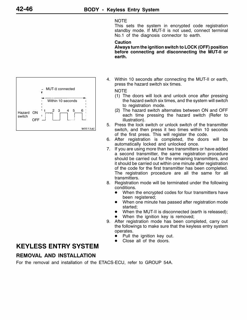
4. Within 10 seconds after connecting the MUT-II or earth,press the hazard switch six times.
NOTE(1) The doors will lock and unlock once after pressing
the hazard switch six times, and the system will switchto registration mode.
(2) The hazard switch alternates between ON and OFFeach time pressing the hazard switch (Refer toillustration).
5. Press the lock switch or unlock switch of the transmitterswitch, and then press it two times within 10 secondsof the first press. This will register the code.
6. After registration is completed, the doors will beautomatically locked and unlocked once.
7. If you are using more than two transmitters or have addeda second transmitter, the same registration procedureshould be carried out for the remaining transmitters, andit should be carried out within one minute after registrationof the code for the first transmitter has been completed.The registration procedure are all the same for alltransmitters.
8. Registration mode will be terminated under the followingconditions.D When the encrypted codes for four transmitters have
been registered;D When one minute has passed after registration mode
started;D When the MUT-II is disconnected (earth is released);D When the ignition key is removed;
9. After registration mode has been completed, carry outthe followings to make sure that the keyless entry systemoperates.D Pull the ignition key out.D Close all of the doors.
KEYLESS ENTRY SYSTEMREMOVAL AND INSTALLATIONFor the removal and installation of the ETACS-ECU, refer to GROUP 54A.
MUT-II connected
Within 10 seconds
Hazardswitch
ON
OFF
1 2 3 4 5 6

BODY - Sunroof 42-47
SUNROOFSERVICE SPECIFICATION
Items Standard value
Roof lid glass operating current A (at 20°C) 7 or less
TROUBLESHOOTINGThe sunroof is controlled by the SWS (Smart Wiring System). For troubleshooting procedures, refer toGROUP 54B - SWS Diagnosis.
ON-VEHICLE SERVICEWATER TESTCheck if there are any leaks in the sunroof by the followingprocedure.1. Fully close the roof lid glass.2. Adjust the water pressure so that water comes out of
the hose to a height of approximately 50 cm when thehose is held vertically facing upwards.
3. Hold the end of the hose approximately 30 cm abovethe roof and let the water run onto the weatherstrip for5 minutes or more.
4. While letting the water run onto the weatherstrip, checkthat there is no water leaking into the passengercompartment.
SUNROOF FIT ADJUSTMENT1. Fully close the roof lid glass.2. Fully open the sunshade.3. Loosen the roof lid glass assembly mounting screws,
and then slide the roof lid glass assembly along the slotin the mechanism assembly to adjust the height of theroof lid glass.
4. After adjustment, check to be sure that the sunroofoperates smoothly.
Hose
Approx. 30cm

BODY - Sunroof42-48
SUNROOFREMOVAL AND INSTALLATION
Post-installation OperationD Sunroof Water Test (Refer to P.42-47.)D Sunroof Fit Adjustment (Refer to P.42-47.)
1
2
3
4
5
6
7
5
<Short wheelbase>
<Long wheelbase>
8
1. Roof lid glass assemblySunroof switch removal steps2. Sunroof switch cover3. Sunroof switchDrain hose removal stepsD HeadliningD Rear mudguard (Rear drain hose)D instrument panel assembly
(Refer to GROUP 52A.)AA" "AA 4. Drain hose (Front side)
D Pillar duct (passenger�s side) (Referto GROUP 55.)
D Rear quarter duct (passenger�s side)(Refer to GROUP 55.)
AA" "AA 5. Drain hose (Rear side)
Sunroof motor assembly removalstepsD Headlining
AB" "BA 6. Sunroof motor assemblySunroof assembly removal stepsD Headlining
AA" "AA 4. Drain hose (Front side)D Pillar duct (passenger�s side) (Refer
to GROUP 55.)D Rear quarter duct (passenger�s side)
(Refer to GROUP 55.)AA" "AA 5. Drain hose (Rear side)
7. Set bracket8. Sunroof assembly

BODY - Sunroof 42-49
REMOVAL SERVICE POINTSAA"DRAIN HOSE REMOVALTie a cord to the end of the drain hose, and wind tape aroundit so that there is no unevenness. Then pull the drain hoseout from the passenger compartment.
AB"SUNROOF MOTOR ASSEMBLY REMOVALCautionAlways close the roof lid glass fully before removingthe sunroof motor. If the fully-closed positions of the rooflid glass and the sunroof motor are not the same, thesunroof will not operate properly.NOTEIf there is a problem with the sunroof motor so that the rooflid glass cannot close fully, use an Allen key to turn the gearsection of the sunroof motor to fully close the roof lid glass.
INSTALLATION SERVICE POINTS"AADRAIN HOSE INSTALLATION1. Tie the cord that was used during removal to the end
of the drain hose, and wind tape around it so that thereis no unevenness.
2. Pull the cord to pull through the drain hose
3. Install the grommet, and then position the drain hoseso that it protrudes from the grommet as shown in theillustration.
Drain hose
Cord
Cord Drain hose
Grommet
20 - 30 mm

BODY - SunroofBODY - Sunroof42-50
"BASUNROOF MOTOR ASSEMBLY INSTALLATION<INSTALLATION OF REMOVED MOTOR ASSEMBLY>1. Install the roof lid glass assembly and the sunroof motor
assembly with the sunroof motor assembly in thefully-closed position.
2. Connect the sunroof motor assembly harness connectorand the sunroof switch harness connector to the vehiclewiring harness connector.
3. Operate the sunroof and check that it operates correctly.
<ACCESSORY (NEW) SUNROOF MOTOR ASSEMBLYINSTALLATION>1. Install the roof lid glass assembly and the sunroof motor
assembly with the sunroof motor assembly in thefully-closed position.
2. Connect the sunroof motor assembly harness connectorand the sunroof switch harness connector to the vehiclewiring harness connector.
3. Operate the sunroof switch to slide the roof lid glassto the fully-open position, and then tilt it up in steps of30 mm to the fully-open position and then keep pressingthe switch for 3 seconds or more.
4. Operate the sunroof switch (CLOSE) using the one-touchfunction to slide the roof lid glass to the fully-closedposition.
5. Operate the sunroof switch (OPEN) using the one-touchfunction to slide the roof lid glass to the fully-open position.
6. Operate the sunroof switch (CLOSE) using the one-touchfunction to slide the roof lid glass to the fully-closedposition.
7. Press the tilt -up switch to operate the sunroof and checkthat learning is complete.NOTE(1) During initialisation (learning mode), use only the
CLOSE/DOWN switch to move the roof lid glass fromthe fully-closed position to the fully tilted open position.During initialisation, the TILT UP switch will not workwhen pressed. Furthermore, the sunroof-ECUwill stoprunning in learning mode as soon as the roof lid glassis tilted up.
(2) When the clamping prevention mechanism iscancelled, the operation is the same as when theroof lid glass operates 30 mm at a time.

BODY - Sunroof 42-51
INSPECTIONROOF LID GLASS OPERATION CURRENT CHECK1. Remove the sunroof fuse and connect a circuit analyser
as shown in the illustration.2. Press the sunroof switch to operate the sunroof, and
then measure the operation current while the roof lidglass ismoving (except when the sunroof starts to operate,when it is fully open, when it is fully closed and whenit is fully tilted up).
Standard value: 7 A or less (at 20_C)3. If the operation current is not within the standard value,
check the following points.D Installation condition, warping or jamming of sunroof
assemblyD Sticking of drive cableD Tilt of roof lid glass
SUNROOF SWITCH CONTINUITY CHECK
Switch position Terminal No.
3 4 5 6
Open
Off
Tilt up
Slide close, Tilt down
Fuse
Slide close,Tilt down Tilt up
Open

BODY - Sunroof42-52
DISASSEMBLY AND REASSEMBLY
1
2
3
4
6
789
11 12
1314
15
5
16
5
16
10
<Short wheelbase>
<Long wheelbase>
Sealant:3M ATD Part No. 8531 or 8646 AutoSealant or equivalent
Section A � A
A
A
Disassembly steps1. Roof lid glass assembly2. Weatherstrip3. Sunroof motor4. Roof drip channel5. Rear drip assembly6. Sun shade assembly7. Drive cable assembly
AA" "AA 8. Shaft
AA" 9. Drive cableAB" 10. Roof window deflector panel assemblyAC" 11. DeflectorAC" 12. Deflector link
13. Set plate14. Front cover15. Cable guide casing16. Guide rail sub-assembly

BODY - Sunroof 42-53
DISASSEMBLY SERVICE POINTSAA"SHAFT/DRIVE CABLE REMOVALAfter pulling out the drive cable assembly as shown in theillustration, remove the shaft and the drive cable.
AB"ROOF WINDOW DEFLECTOR PANEL ASSEMBLYREMOVAL
Twist a flat-tipped screwdriver or similar tool as shown inthe illustration to remove the roof window deflector panelassembly.
AC" DEFLECTOR/DEFLECTOR LINK REMOVALUse a flat-tipped screwdriver or similar tool to separate thedeflector and the deflector panel as shown in the illustration.
Shaft
Guide rail sub-assembly
Drive cable assembly
Approx.200 mm
Flat-tippedscrewdriver
Flat-tippedscrewdriver
A
Section A - A
A
Roof windowdeflector panelassembly
Roof windowdeflector panelassembly
Guide rail sub-assembly
Section A - A
A
A
Flat-tippedscrewdriver
Deflector
Deflector link
Flat-tippedscrewdriver

BODY - Sunroof42-54
REASSEMBLY SERVICE POINT"AA SHAFT INSTALLATIONWorking outside the vehicle, install the shaft to the drive cable according to the procedure below.
Drive cable assembly
Shaft
Shaftinsertiondirection
A
A
Section A - A
Hollow in shaft
Raised section of drivecable assembly
Drive cable assembly
Shaft
Insert the shaft until its concave part is engagedwith the convex part of the drive cable.
Front sideof vehicle