WORKSHOP MANUAL for V2203-DI (26--00128)dms.hvacpartners.com/docs/2000/Public/0D/62-11362.pdf ·...
73
Diesel Engine 62--11362 Rev A WORKSHOP MANUAL for V2203-DI (26--00128) Tier 4i R
-
Upload
dangkhuong -
Category
Documents
-
view
235 -
download
2
Transcript of WORKSHOP MANUAL for V2203-DI (26--00128)dms.hvacpartners.com/docs/2000/Public/0D/62-11362.pdf ·...

Diesel Engine
62--11362 Rev A
WORKSHOP MANUALfor
V2203-DI (26--00128)Tier 4i
R

WORKSHOP MANUAL
DIESEL ENGINE
V2203-DI (26-00118)Tier 4i

i 62--11362
TABLE OF CONTENTS
PARAGRAPH NUMBER Page
SAFETY PRECAUTIONS iv. . . . . . . . . . . . . . . . . . . . . . . . . . . . . . . . . . . . . . . . . . . . . . . . . . . . . . . . . . . . . . . . . . .
SPECIFIC WARNING AND CAUTION STATEMENTS iv. . . . . . . . . . . . . . . . . . . . . . . . . . . . . . . . . . . . . . . . . .
General 1--1. . . . . . . . . . . . . . . . . . . . . . . . . . . . . . . . . . . . . . . . . . . . . . . . . . . . . . . . . . . . . . . . . . . . . . . . . . . . . . . . . . . . . .
1.1 ENGINE IDENTIFICATION 1--1. . . . . . . . . . . . . . . . . . . . . . . . . . . . . . . . . . . . . . . . . . . . . . . . . . . . . . . . . . . .
1.2 ENGINE SPECIFICATIONS 1--2. . . . . . . . . . . . . . . . . . . . . . . . . . . . . . . . . . . . . . . . . . . . . . . . . . . . . . . . . . . .
1.3 CYLINDER NUMBER 1--3. . . . . . . . . . . . . . . . . . . . . . . . . . . . . . . . . . . . . . . . . . . . . . . . . . . . . . . . . . . . . . . . .
1.4 GENERAL PRECAUTIONS 1--3. . . . . . . . . . . . . . . . . . . . . . . . . . . . . . . . . . . . . . . . . . . . . . . . . . . . . . . . . . . .
1.5 TORQUE SPECIFICATIONS 1--4. . . . . . . . . . . . . . . . . . . . . . . . . . . . . . . . . . . . . . . . . . . . . . . . . . . . . . . . . . .
1.5.1 Torque Specifications For Special Use Screws, Bolts and Nuts 1--4. . . . . . . . . . . . . . . . . . . . . . . . . .
1.5.2 Torque Specifications For General Use Screws, Bolts and Nuts 1--4. . . . . . . . . . . . . . . . . . . . . . . . . .
1.6 TROUBLESHOOTING 1--5. . . . . . . . . . . . . . . . . . . . . . . . . . . . . . . . . . . . . . . . . . . . . . . . . . . . . . . . . . . . . . . .
1.7 SERVICING SPECIFICATIONS 1--7. . . . . . . . . . . . . . . . . . . . . . . . . . . . . . . . . . . . . . . . . . . . . . . . . . . . . . . .
1.7.1 Engine Body 1--7. . . . . . . . . . . . . . . . . . . . . . . . . . . . . . . . . . . . . . . . . . . . . . . . . . . . . . . . . . . . . . . . . . . . . .
1.7.2 Lubricating System 1--11. . . . . . . . . . . . . . . . . . . . . . . . . . . . . . . . . . . . . . . . . . . . . . . . . . . . . . . . . . . . . . . .
1.7.3 Cooling System 1--11. . . . . . . . . . . . . . . . . . . . . . . . . . . . . . . . . . . . . . . . . . . . . . . . . . . . . . . . . . . . . . . . . . .
1.7.4 Fuel System 1--11. . . . . . . . . . . . . . . . . . . . . . . . . . . . . . . . . . . . . . . . . . . . . . . . . . . . . . . . . . . . . . . . . . . . . .
1.7.5 Electrical System 1--12. . . . . . . . . . . . . . . . . . . . . . . . . . . . . . . . . . . . . . . . . . . . . . . . . . . . . . . . . . . . . . . . . .
1.8 CHECK AND MAINTENANCE 1--13. . . . . . . . . . . . . . . . . . . . . . . . . . . . . . . . . . . . . . . . . . . . . . . . . . . . . . . . . .
1.8.1 Checking Engine Oil Level 1--13. . . . . . . . . . . . . . . . . . . . . . . . . . . . . . . . . . . . . . . . . . . . . . . . . . . . . . . . . .
1.8.2 Checking Coolant Level 1--13. . . . . . . . . . . . . . . . . . . . . . . . . . . . . . . . . . . . . . . . . . . . . . . . . . . . . . . . . . . .
1.8.3 Checking Fuel Hose 1--13. . . . . . . . . . . . . . . . . . . . . . . . . . . . . . . . . . . . . . . . . . . . . . . . . . . . . . . . . . . . . . .
1.8.4 Bleeding Fuel System 1--14. . . . . . . . . . . . . . . . . . . . . . . . . . . . . . . . . . . . . . . . . . . . . . . . . . . . . . . . . . . . . .
1.8.5 Checking V--Belt 1--14. . . . . . . . . . . . . . . . . . . . . . . . . . . . . . . . . . . . . . . . . . . . . . . . . . . . . . . . . . . . . . . . . .
1.8.6 Changing Engine Oil 1--14. . . . . . . . . . . . . . . . . . . . . . . . . . . . . . . . . . . . . . . . . . . . . . . . . . . . . . . . . . . . . . .
1.8.7 Valve Clearance 1--15. . . . . . . . . . . . . . . . . . . . . . . . . . . . . . . . . . . . . . . . . . . . . . . . . . . . . . . . . . . . . . . . . .
1.8.8 Fuel Injection 1--15. . . . . . . . . . . . . . . . . . . . . . . . . . . . . . . . . . . . . . . . . . . . . . . . . . . . . . . . . . . . . . . . . . . . .
1.9 SPECIAL TOOLS 1--16. . . . . . . . . . . . . . . . . . . . . . . . . . . . . . . . . . . . . . . . . . . . . . . . . . . . . . . . . . . . . . . . . . . . .
1.9.1 Diesel Engine Compression Tester (Glow Plug) 1--16. . . . . . . . . . . . . . . . . . . . . . . . . . . . . . . . . . . . . . .
1.9.2 Adapter, Injector To Tester Hose 1--16. . . . . . . . . . . . . . . . . . . . . . . . . . . . . . . . . . . . . . . . . . . . . . . . . . . .
1.9.3 Tester Injector Nozzle 1--16. . . . . . . . . . . . . . . . . . . . . . . . . . . . . . . . . . . . . . . . . . . . . . . . . . . . . . . . . . . . . .
1.9.4 Replacement Bowl, Tester Injector Nozzle 1--16. . . . . . . . . . . . . . . . . . . . . . . . . . . . . . . . . . . . . . . . . . . .
1.9.5 Adapter, Injector Line 1--16. . . . . . . . . . . . . . . . . . . . . . . . . . . . . . . . . . . . . . . . . . . . . . . . . . . . . . . . . . . . . .
1.9.6 Oil Pressure Tester 1--17. . . . . . . . . . . . . . . . . . . . . . . . . . . . . . . . . . . . . . . . . . . . . . . . . . . . . . . . . . . . . . . .
1.9.7 Auxiliary Socket For Fixing Crankshaft Sleeve 1--17. . . . . . . . . . . . . . . . . . . . . . . . . . . . . . . . . . . . . . . .
1.9.8 Gauge, Belt Tension 1--17. . . . . . . . . . . . . . . . . . . . . . . . . . . . . . . . . . . . . . . . . . . . . . . . . . . . . . . . . . . . . . .
1.9.9 Tester, Belt Tension 1--17. . . . . . . . . . . . . . . . . . . . . . . . . . . . . . . . . . . . . . . . . . . . . . . . . . . . . . . . . . . . . . . .
1.9.10 Rubber Band 1--17. . . . . . . . . . . . . . . . . . . . . . . . . . . . . . . . . . . . . . . . . . . . . . . . . . . . . . . . . . . . . . . . . . . . .
1.9.11 Main Bearing Install Tool 1--17. . . . . . . . . . . . . . . . . . . . . . . . . . . . . . . . . . . . . . . . . . . . . . . . . . . . . . . . . . .
1.9.12 Main Bearing Extract Tool 1--17. . . . . . . . . . . . . . . . . . . . . . . . . . . . . . . . . . . . . . . . . . . . . . . . . . . . . . . . . .
1.9.13 Valve Guide Replacing Tool 1--18. . . . . . . . . . . . . . . . . . . . . . . . . . . . . . . . . . . . . . . . . . . . . . . . . . . . . . . . .
1.9.14 Bushing Replacing Tools 1--18. . . . . . . . . . . . . . . . . . . . . . . . . . . . . . . . . . . . . . . . . . . . . . . . . . . . . . . . . . .
1.9.15 Flywheel Stopper 1--18. . . . . . . . . . . . . . . . . . . . . . . . . . . . . . . . . . . . . . . . . . . . . . . . . . . . . . . . . . . . . . . . . .
1.9.16 Crankshaft Bearing 1 Replacing Tool 1--19. . . . . . . . . . . . . . . . . . . . . . . . . . . . . . . . . . . . . . . . . . . . . . . . .

ii62-11362
PARAGRAPH NUMBER PageENGINE BODY 2--1. . . . . . . . . . . . . . . . . . . . . . . . . . . . . . . . . . . . . . . . . . . . . . . . . . . . . . . . . . . . . . . . . . . . . . . . . . . . . . .
2.1 CHECKING AND ADJUSTING 2--1. . . . . . . . . . . . . . . . . . . . . . . . . . . . . . . . . . . . . . . . . . . . . . . . . . . . . . . . .
2.1.1 Compression Pressure 2--1. . . . . . . . . . . . . . . . . . . . . . . . . . . . . . . . . . . . . . . . . . . . . . . . . . . . . . . . . . . . .
2.1.2 Top Clearance 2--1. . . . . . . . . . . . . . . . . . . . . . . . . . . . . . . . . . . . . . . . . . . . . . . . . . . . . . . . . . . . . . . . . . . .
2.2 DISASSEMBLY AND REASSEMBLY 2--2. . . . . . . . . . . . . . . . . . . . . . . . . . . . . . . . . . . . . . . . . . . . . . . . . . . .
2.2.1 Draining Coolant And Engine Oil 2--2. . . . . . . . . . . . . . . . . . . . . . . . . . . . . . . . . . . . . . . . . . . . . . . . . . . .
2.2.2 External Components 2--2. . . . . . . . . . . . . . . . . . . . . . . . . . . . . . . . . . . . . . . . . . . . . . . . . . . . . . . . . . . . . .
2.2.3 Cylinder Head And Valves 2--3. . . . . . . . . . . . . . . . . . . . . . . . . . . . . . . . . . . . . . . . . . . . . . . . . . . . . . . . . .
2.2.4 Injection Pump and Gear Case 2--6. . . . . . . . . . . . . . . . . . . . . . . . . . . . . . . . . . . . . . . . . . . . . . . . . . . . . .
2.2.5 Oil Pan and Oil Strainer 2--12. . . . . . . . . . . . . . . . . . . . . . . . . . . . . . . . . . . . . . . . . . . . . . . . . . . . . . . . . . . .
2.2.6 Piston and Connecting Rod 2--13. . . . . . . . . . . . . . . . . . . . . . . . . . . . . . . . . . . . . . . . . . . . . . . . . . . . . . . . .
2.2.7 Crankshaft 2--15. . . . . . . . . . . . . . . . . . . . . . . . . . . . . . . . . . . . . . . . . . . . . . . . . . . . . . . . . . . . . . . . . . . . . . .
2.3 SERVICING 2--18. . . . . . . . . . . . . . . . . . . . . . . . . . . . . . . . . . . . . . . . . . . . . . . . . . . . . . . . . . . . . . . . . . . . . . . . .
2.3.1 Cylinder Head And Valves 2--18. . . . . . . . . . . . . . . . . . . . . . . . . . . . . . . . . . . . . . . . . . . . . . . . . . . . . . . . . .
2.3.2 Timing Gears, Camshaft and Fuel Camshaft 2--23. . . . . . . . . . . . . . . . . . . . . . . . . . . . . . . . . . . . . . . . . .
2.3.3 Piston and Connecting Rod 2--26. . . . . . . . . . . . . . . . . . . . . . . . . . . . . . . . . . . . . . . . . . . . . . . . . . . . . . . . .
2.3.4 Crankshaft 2--28. . . . . . . . . . . . . . . . . . . . . . . . . . . . . . . . . . . . . . . . . . . . . . . . . . . . . . . . . . . . . . . . . . . . . . .
2.3.5 Cylinder 2--33. . . . . . . . . . . . . . . . . . . . . . . . . . . . . . . . . . . . . . . . . . . . . . . . . . . . . . . . . . . . . . . . . . . . . . . . . .
LUBRICATING SYSTEM 3--1. . . . . . . . . . . . . . . . . . . . . . . . . . . . . . . . . . . . . . . . . . . . . . . . . . . . . . . . . . . . . . . . . . . . . . .
3.1 CHECKING AND ADJUSTING 3--1. . . . . . . . . . . . . . . . . . . . . . . . . . . . . . . . . . . . . . . . . . . . . . . . . . . . . . . . .
3.1.1 Engine Oil Pressure 3--1. . . . . . . . . . . . . . . . . . . . . . . . . . . . . . . . . . . . . . . . . . . . . . . . . . . . . . . . . . . . . . .
3.2 SERVICING 3--2. . . . . . . . . . . . . . . . . . . . . . . . . . . . . . . . . . . . . . . . . . . . . . . . . . . . . . . . . . . . . . . . . . . . . . . . .
3.2.1 Rotor Lobe Clearance 3--2. . . . . . . . . . . . . . . . . . . . . . . . . . . . . . . . . . . . . . . . . . . . . . . . . . . . . . . . . . . . .
3.2.2 Rotor to Cover Clearance 3--2. . . . . . . . . . . . . . . . . . . . . . . . . . . . . . . . . . . . . . . . . . . . . . . . . . . . . . . . . .
COOLING SYSTEM 4--1. . . . . . . . . . . . . . . . . . . . . . . . . . . . . . . . . . . . . . . . . . . . . . . . . . . . . . . . . . . . . . . . . . . . . . . . . . .
4.1 CHECKING AND ADJUSTING 4--1. . . . . . . . . . . . . . . . . . . . . . . . . . . . . . . . . . . . . . . . . . . . . . . . . . . . . . . . .
4.1.1 Notched V--Belt Service 4--1. . . . . . . . . . . . . . . . . . . . . . . . . . . . . . . . . . . . . . . . . . . . . . . . . . . . . . . . . . . .
4.1.1a Poly V--Belt Service 4--1. . . . . . . . . . . . . . . . . . . . . . . . . . . . . . . . . . . . . . . . . . . . . . . . . . . . . . . . . . . . . . .
4.1.2 Fan Belt Damage and Wear 4--1. . . . . . . . . . . . . . . . . . . . . . . . . . . . . . . . . . . . . . . . . . . . . . . . . . . . . . . .
4.1.3 Checking Coolant Level 4--1. . . . . . . . . . . . . . . . . . . . . . . . . . . . . . . . . . . . . . . . . . . . . . . . . . . . . . . . . . . .
4.1.4 Radiator Cap 4--2. . . . . . . . . . . . . . . . . . . . . . . . . . . . . . . . . . . . . . . . . . . . . . . . . . . . . . . . . . . . . . . . . . . . .
4.1.5 Radiator 4--2. . . . . . . . . . . . . . . . . . . . . . . . . . . . . . . . . . . . . . . . . . . . . . . . . . . . . . . . . . . . . . . . . . . . . . . . .
4.1.6 Thermostat Opening Temperature 4--2. . . . . . . . . . . . . . . . . . . . . . . . . . . . . . . . . . . . . . . . . . . . . . . . . . .
4.2 SERVICING 4--3. . . . . . . . . . . . . . . . . . . . . . . . . . . . . . . . . . . . . . . . . . . . . . . . . . . . . . . . . . . . . . . . . . . . . . . . .
4.2.1 Thermostat Assembly 4--3. . . . . . . . . . . . . . . . . . . . . . . . . . . . . . . . . . . . . . . . . . . . . . . . . . . . . . . . . . . . . .
4.2.2 Water Pump Assembly 4--3. . . . . . . . . . . . . . . . . . . . . . . . . . . . . . . . . . . . . . . . . . . . . . . . . . . . . . . . . . . . .

iii 62--11362
PARAGRAPH NUMBER PageFUEL SYSTEM 5--1. . . . . . . . . . . . . . . . . . . . . . . . . . . . . . . . . . . . . . . . . . . . . . . . . . . . . . . . . . . . . . . . . . . . . . . . . . . . . . .
5.1 CHECKING AND ADJUSTING 5--1. . . . . . . . . . . . . . . . . . . . . . . . . . . . . . . . . . . . . . . . . . . . . . . . . . . . . . . . .
5.1.1 Injection Timing 5--1. . . . . . . . . . . . . . . . . . . . . . . . . . . . . . . . . . . . . . . . . . . . . . . . . . . . . . . . . . . . . . . . . . .
5.1.2 Shim Identification 5--1. . . . . . . . . . . . . . . . . . . . . . . . . . . . . . . . . . . . . . . . . . . . . . . . . . . . . . . . . . . . . . . . .
5.1.3 Pump Pressure Test 5--2. . . . . . . . . . . . . . . . . . . . . . . . . . . . . . . . . . . . . . . . . . . . . . . . . . . . . . . . . . . . . . .
5.1.4 Delivery Valve Fuel Seal 5--2. . . . . . . . . . . . . . . . . . . . . . . . . . . . . . . . . . . . . . . . . . . . . . . . . . . . . . . . . . .
5.2 INJECTION NOZZLE 5--3. . . . . . . . . . . . . . . . . . . . . . . . . . . . . . . . . . . . . . . . . . . . . . . . . . . . . . . . . . . . . . . . .
5.2.1 Nozzle Injection Pressure 5--3. . . . . . . . . . . . . . . . . . . . . . . . . . . . . . . . . . . . . . . . . . . . . . . . . . . . . . . . . .
5.2.2 Nozzle Spraying Condition 5--3. . . . . . . . . . . . . . . . . . . . . . . . . . . . . . . . . . . . . . . . . . . . . . . . . . . . . . . . . .
5.2.3 Valve Seat Tightness 5--3. . . . . . . . . . . . . . . . . . . . . . . . . . . . . . . . . . . . . . . . . . . . . . . . . . . . . . . . . . . . . .
ELECTRICAL SYSTEM 6--1. . . . . . . . . . . . . . . . . . . . . . . . . . . . . . . . . . . . . . . . . . . . . . . . . . . . . . . . . . . . . . . . . . . . . . . .
6.1 STARTER TEST 6--1. . . . . . . . . . . . . . . . . . . . . . . . . . . . . . . . . . . . . . . . . . . . . . . . . . . . . . . . . . . . . . . . . . . . . .
6.1.1 Motor Test 6--1. . . . . . . . . . . . . . . . . . . . . . . . . . . . . . . . . . . . . . . . . . . . . . . . . . . . . . . . . . . . . . . . . . . . . . . .
6.1.2 Magnetic Switch Test 6--1. . . . . . . . . . . . . . . . . . . . . . . . . . . . . . . . . . . . . . . . . . . . . . . . . . . . . . . . . . . . . .
6.2 FUEL SPEED SOLENOID 6--2. . . . . . . . . . . . . . . . . . . . . . . . . . . . . . . . . . . . . . . . . . . . . . . . . . . . . . . . . . . . .
6.2.1 Solenoid Test 6--2. . . . . . . . . . . . . . . . . . . . . . . . . . . . . . . . . . . . . . . . . . . . . . . . . . . . . . . . . . . . . . . . . . . . .
6.3 INTAKE AIR HEATER 6--3. . . . . . . . . . . . . . . . . . . . . . . . . . . . . . . . . . . . . . . . . . . . . . . . . . . . . . . . . . . . . . . . .
6.3.1 Intake Air Heater Test 6--3. . . . . . . . . . . . . . . . . . . . . . . . . . . . . . . . . . . . . . . . . . . . . . . . . . . . . . . . . . . . . .

iv 62-11362
SAFETYSAFETY PRECAUTIONS
Your Carrier Transicold unit has been designed with thesafety of the operator in mind. During normal operation,all moving parts are fully enclosed to help prevent injury.During all pre-trip inspections, daily inspections, andproblem troubleshooting, you may be exposed tomoving parts. Please stay clear of all moving parts whenthe unit is in operation and when the unit main powerswitch is in the START/RUN position.
Engine CoolantThe engine is equipped with a pressurized coolingsystem. Under normal operating conditions, the coolantin the engine and radiator is under high pressure and isvery hot. Contact with hot coolant can cause severeburns. Do not remove the cap from a hot radiator. If the
cap must be removed, do so very slowly in order torelease the pressure without spray.
BatteryThis unit is equipped with a lead-acid type battery. Thebattery normally vents small amounts of flammablehydrogen gas. Do not smoke when checking the battery.A battery explosion can cause serious physical harmand/or blindness.
SPECIFIC WARNING AND CAUTIONSTATEMENTS
To help identify the label hazards on the unit and explainthe level of awareness each one carries, an explanationis given with the appropriate consequences:
DANGERDANGER -- warns against an immediate hazard which WILL result in severe personal injury or death.
WARNINGWARNING -- warns against hazards or unsafe conditions which COULD result in severe personal in-jury or death.
CAUTIONCAUTION -- warns against potential hazard or unsafe practice which could result in minor personalinjury, or product or property damage.
NOTE
NOTE -- gives helpful information that may help and avoid equipment and property damage.

v 62-11362
The statements listed below are specifically applicable to this unit and appear elsewhere in this manual. Theserecommended precautions must be understood and applied during operation and maintenance of the equipmentcovered herein.
WARNINGBeware of moving V--belt and belt driven components
WARNINGWhen removing the radiator cap, wait at least ten minutes after the engine has stopped and cooleddown. Otherwise, hot water may discharge from the radiator, scalding anyone nearby.
WARNINGCheck the injection nozzle only after confirming that nobody is near the spray. If the spray from thenozzle contacts the human body, cells may be destroyed and blood poisoning may result.
WARNINGSecure the starter to prevent it from moving when power is applied to it.
CAUTIONDo not remove the radiator cap until the coolant temperature is below its boiling point. Loosen thecap slightly to relieve excess pressure before removing the cap completely.
CAUTIONStop the engine when attempting to check and change the fuel line.
CAUTIONStop the engine when preparing to change the engine oil.
CAUTIONNever remove the radiator cap until coolant temperature is below its boiling point. Loosen the capslightly to the first stop to relieve any excess pressure before removing the cap completely.

1--1 62--11362
SECTION 1
General
1.1 ENGINE IDENTIFICATION
S/N
When contacting Carrier Transicold, always specifyyour engine model number and serial number.
The engine model and its serial number need to beidentified before the engine can be serviced or partsreplaced.
Engine Serial Number
The engine serial number is an identified number for theengine. It is marked after the engine model number.
It indicates month and year of manufacture as follows:
ENGINE SERIAL NUMBER MATRIX
Serial Number7 K A
Last 3 Digits in Numerals (1 to 999 Units in Sequence)
6th Digit Alpabetical Letter (Month of Manufacture -- 1st Letter 1--9999 Units, 2nd Letter 10,000--19,998 Units)Alphabetical letter A,B C,D E,F G,H J,K L,M N,P Q,R S,T U,V W,X Y,ZMonth
5th Digit Alpabetical Letter or Numerals (Year of Manufacture)Alphabetical letter or numerals W X YYear 98 99 00 01 02 03 04 05 06 07 08 09
Jan Feb Mar May Jun Jul Aug Sep OctApr Nov Dec
1 2 3 4 5 6 7 8 9
Z482--
Basic model number
176
7th Digit Sequential Numeral or Letter (Units Manufactured)Alphabetical Numeral or LetterUnit Number Sequence 19,999--20997 20,998--21,996
B C21,997--22,995
0 to 9
A B C D E1413121110
to 19,998A
Table 1-1. Model Chart
MODEL NUMBER ENGINE TYPESERVICE ENGINE
PART NUMBERPRIMARY USE REPLACES
V2203L--DI--E3B--CTD--2CT4--134--DI(1700 RPM)
26--00128--00Ultra XT, Ultra XTC, X2 1800 (2.2),
X2 2100, X2 2100A, X2 2100RNew
V2203L--DI--E3B--CTD--3CT4--134--DI(1800 RPM)
26--00128--01 RG Genset New
V2203L--DI--E3B--CTD--1CT4--134--DI(2200 RPM)
26--00128--02Ultima XTC, Extra XT (2.2),
X2 2500 A, X2 2500 RNew
V2203L--DI--E3B--CTD--6CT4--134--DI(1800 RPM)
26--00128--04 UG Genset New
V2203L--DI--E3B--CTD--4CT4--134--DI(1700 RPM)
26--00128--05 TM Ultra XL New

1--262--11632
1.2 ENGINE SPECIFICATIONS
Table 1-2. Specification Chart
MODEL NUMBER 26--00128--00 26--00128--01 26--00128--02 26--00128--04 26--00128--05
TYPE Vertical, Water--cooled, 4 cycle diesel engine
NUMBER OF CYLINDERS 4
BORE X STROKE mm X mm (in. X in.) 83 X 102.4 (3.27 X 4.03)
TOTAL DISPLACEMENT cm3 (cu.in.) 2216 (135.2)
BRAKE HORSEPOWERSAE Intermittent HP kW (HP) / RPM
23.65 (31.7) /1700
23.87 (32.0) /1800
26.85 (36.0) /2200
23.87 (32.0) /1800
23.65 (31.7) /1700
MAXIMUM SPEED RPM Below 2470
IDLING SPEED RPM 900
COMBUSTION CHAMBER Direct Injection
INJECTION PUMP Bosch “K” Type Mini Pump
GOVERNOR Mechanical Governor + Electronic Governor
INJECTION NOZZLE Bosch “P” Type Hole Nozzle
INJECTION TIMING (UNPRESSURIZED) 2.5° Before T.D.C.4.0° Before
T.D.C.2.5° Before T.D.C.
FIRING ORDER 1--3--4--2
INJECTION PRESSURE(Valve Opening Pressure)
19.35 MPa (197.5 kgf/cm2, 2809 psi.)
COMPRESSION RATIO 21.5 : 1
LUBRICATION SYSTEM Forced Lubrication by Pump
OIL PRESSURE INDICATION Electrical Type Switch
LUBRICATION FILTER Full Flow Synthetic Media Filter (Cartridge Type)
COOLING SYSTEM Pressurized Radiator, Forced Circulation With Water Pump
STARTING SYSTEMElectric Starting With Starting Motor
12V, 2.5 kW
STARTING SUPPORT DEVICE Intake Air Heater in Intake Manifold
FUEL Diesel Fuel No.2--D (ASTM D975)
LUBRICATING OIL *Quality Better Than CF Class (API), SAE 10W--30 or 15W--40
LUBRICATING OIL CAPACITY 14.2 L (15.0 U.S. Quarts)
Weight (DRY) kg (lbs.) 199 (439)
*See paragraph 1.8.6

1--3 62--11362
1.3 CYLINDER NUMBER
The cylinder numbers of V2203--DI series engine aredesignated as shown above. The sequence of cylindernumbers is given as No.1, No. 2, No. 3, and No. 4starting from the gear case end of the engine.
1.4 GENERAL PRECAUTIONS
1
2
32
3
1. Grease2. Force3. Place the Sharp Edge
against the Direction of Force
A External Snap Ring
B Internal Snap Ring
During disassembly, carefully arrange removed parts ina clean area to prevent confusion later. Screws, boltsand nuts should be replaced in their original position toprevent reassembly errors.
When special tools are required, use KUBOTA genuinespecial tools. Special tools which are not frequentlyused should be made according to the drawingsprovided.
Before disassembling or servicing live wires, make sureto always disconnect the grounding cable from thebattery first.
Remove oil and dirt from parts before taking anymeasurements.
Use only Carrier Transicold genuine parts for partsreplacements to maintain engine performance and toensure safety.
Gaskets and O--rings must be replaced duringreassembly. Apply grease to new O--rings or oil sealsbefore assembling.
When reassembling external or internal snap rings,position them so that the sharp edge faces against thedirection from which force is applied.
A newly serviced or reassembled engine should berun--in with no load for 15 minutes. Serious damage tothe engine may result otherwise.

1--462--11632
1.5 TORQUE SPECIFICATIONS
Screws, bolts and nuts must be tightened to the specified torque using a torque wrench. Several screws, bolts andnuts such as those used on the cylinder head must be tightened in the proper sequence and at the proper torque.
1.5.1 Torque Specifications For Special Use Screws, Bolts and NutsIn removing and applying the screws, bolts and nuts marked with “*”, a pneumatic wrench or similar tool, if employed,must be used with care. Failure to do so may result in stripped or seized screws, bolts and nuts.
When replacing “*” marked screws, bolt and nuts, apply engine oil to their threads and seats before reassembly.
The letter “M” in size and pitch means that the screw, bolt or nut dimension is metric. The size is the nominal outsidediameter in mm of the threads. The pitch is the nominal distance in mm between two threads.
Item Size x Pitch N.m kgf.m ft--lbsCylinder Head Cover Bolt M6 x 1.0 6.87 to 11.2 0.7 to 1.15 5.07 to 8.31
*Cylinder Head Bolt M11 x 1.25 93.2 to 98.0 9.5 to 10.0 68.8 to 72.3*Main Bearing Case Bolt 1 M9 x 1.25 46 to 50 4.7 to 5.2 34.0 to 37*Main Bearing Case Bolt 2 M10 x 1.25 69 to 73 7.0 to 7.5 51 to 54*Flywheel Bolt M12 x 1.25 98.1 to 107 10.0 to 11.0 72.4 to 79.5*Connecting Rod Bolt M8 x 1.0 45 to 49 4.5 to 5.0 33 to 36*Rocker Arm Bracket Bolt M8 x 1.25 24 to 27 2.4 to 2.8 18 to 20*Idle Gear Shaft Bolt M8 x 1.25 24 to 27 2.4 to 2.8 18 to 20
Crank Pulley Mounting Nut M30 x 1.5 138 to 156 14.0 to 16.0 102 to 115*Bearing Case Cover Bolt M8 x 1.25 24 to 27 2.4 to 2.8 18 to 20Nozzle Holder Clamp Bolt M10 x 1.25 26 to 29 2.6 to 3.0 19 to 21Injection Pipe Retaining Nut M12 x 1.5 15 to 24 1.5 to 2.5 11 to 18Overflow Pipe Assembly Retaining Bolt M6 x 1.0 9.81 to 11.2 1.0 to 1.15 7.24 to 8.31Camshaft Retaining Bolt M8 x 1.25 24 to 27 2.4 to 2.8 18 to 20Hi--idling Body M14 x 1.0 45 to 49 4.5 to 5.0 33 to 36Starter’s Terminal B Mounting Nut M8 9.8 to 11 1.0 to 1.2 7.3 to 8.6
1.5.2 Torque Specifications For General Use Screws, Bolts and Nuts
Standard Screw and BoltGrade 4
Special Screw and BoltGrade 7
N.m kgf.m ft--lbs N.m kgf.m ft--lbsM6 7.9 to 9.3 0.80 to 0.95 5.8 to 6.8 9.81 to 11.2 1.00 to 1.15 7.24 to 8.31M8 18 to 20 1.8 to 2.1 13 to 15 24 to 27 2.4 to 2.8 18 to 20M10 40 to 45 4.0 to 4.6 29 to 33 49 to 55 5.0 to 5.7 37 to 41M12 63 to 72 6.4 to 7.4 47 to 53 78 to 90 7.9 to 9.2 58 to 66
Screw and bolt material grades are shown by numbers punched on the screw and bolt heads. Prior to tightening, besure to check out the numbers as shown below
Punched Number Screw And Bolt Material GradeNone or 4 Standard Screw And Bolt SS41, S20C
7 Special Screw And Bolt S43C, S48C (Refined)

1--5 62--11362
1.6 TROUBLESHOOTING
Symptom Probable Cause Solution ReferenceEngine Does NotStart
(Starter Does NotRun)
No fuelAir in the fuel systemWater in the fuel system
Fuel pipe cloggedFuel filter cloggedExcessively high viscosity fo fuel or engine oilat low temperature
Fuel with low cetane numberIncorrect injection timingInjection nozzle cloggedInjection pump malfunctioningSeizure of crankshaft, camshaft, piston,cylinder or bearing
Compression leak from cylinder
Improper valve timing
Piston ring and cylinder wornExcessive valve clearance
Battery dischargedStarter malfunctioningKey switch malfunctioningWiring disconnected
Replenish fuelVent AirChange fuel andrepair or replace fuelsystemCleanClean or changeUse specified fuel orengine oil
Use specified fuelAdjustReplaceReplaceRepair or Replace
Replace headgasket, tightencylinder head screw,glow plug and nozzleholder
Correct or replacetiming gear
ReplaceAdjust
ChargeRepair or replaceRepair or replaceConnect
--1.8.41.8.4
1.8.4----
--5.1.11.8.8
----
--------
2.2.4.f
2.3.3.d1.8.7
6.1----
Engine RevolutionIs Not Smooth
Fuel filter clogged or dirtyAir cleaner clogged or dirtyFuel leak due to loose injection pipe retainingnut
Injection pump malfunctioningIncorrect nozzle injection pressureInjection nozzle stuck or clogged
Clean or changeClean or changeTighten retaining nut
ReplaceReplaceReplace
1.8.4----
5.15.2.15.2.3
Either White or BlueExhaust Gas IsObserved
Excessive engine oil
Piston ring and liner worn or ring stuckIncorrect Injection timingDeficient compression
Reduce to specifiedlevel
Repair or replaceAdjustCheck the cylindercompressionpressure and topclearance
1.8.1
2.3.3.d5.1.12.1.1
Either Black or DarkExhaust Gas IsObserved
OverloadLow grade fuel usedFuel filter cloggedAir cleaner cloggedDeficient nozzle injection
Lesson loadUse specified fuelClean or changeClean or changeReplace nozzle
--------
1.8.8
Deficient Output Incorrect injection timingEngine’s moving parts seem to be seizingInjection pump malfunctioningDeficient nozzle injectionCompression leak
Gas leak from exhaust systemAir cleaner dirty or clogged
AdjustRepair or replaceReplaceReplace nozzleCheck thecompressionpressure and repairRepair or replaceClean or replace
5.1.1--
5.15.2.22.1.1
----

1--662--11632
1.6 TROUBLESHOOTING (Continued)
Symptom Probable Cause Solution ReferenceExcessive LubricantOil Consumption
Piston ring’s gap facing the same direction
Oil ring worn or stuckPiston ring groove wornValve stem and valve guide wornCrankshaft bearing, and crank pin bearingworn
Oil leaking due to defective seals or packing
Shift ring gapdirection
ReplaceReplace worn pistonReplaceReplace
Replace
2.2.6.a
2.3.3.d2.3.3.e2.3.1.d2.3.4
--Fuel Mixed intoLubricant Oil
Injection pump’s plunger worn
Deficient nozzle injectionInjection pump broken
Replace Injectionpump
Replace nozzleReplace
5.1
5.2.35.1
Water Mixed intoLubricant Oil
Head gasket defectiveCylinder block or cylinder head flawed
ReplaceReplace
2.2.3.e--
Low Oil Pressure Engine oil level lowOil strainer cloggedRelief valve stuck with dirtRelief valve spring weak or brokenExcessive oil clearance of crankshaft bearing
Excessive oil clearance of crankpin bearing
Excessive oil clearance of rocker armOil passage cloggedIncorrect oil type
Oil pump defective
ReplenishCleanCleanReplaceReplace
Replace
ReplaceCleanUse specified type ofoil
Repair or replace
----
3.1.13.1.1
2.3.4.d
2.3.4.c
2.3.1.k----
3.2High Oil Pressure Incorrect oil type
Relief valve defective
Use specified type ofoil
Replace
--
3.1.1Engine Overheated Engine oil level low
Fan belt broken or elongatedCoolant insufficientRadiator net and radiator fin clogged with dustInside of radiator corrodedCoolant flow route corrodedRadiator cap defectiveOverload runningHead gasket defectiveIncorrect injection timingUnsuitable fuel used
ReplenishReplace or adjustReplenishCleanClean or replaceClean or replaceReplaceLoosen loadReplaceAdjustUse specified fuel
----------------
2.2.3.e----
Low Battery Charge Battery electrolyte level low
Fan belt slips
Wiring disconnectedRectifier defectiveAlternator defectiveBattery defective
Replenish distilledwater and charge
Adjust belt tension orchange belt
ConnectReplaceReplaceChange
--
--
--------

1--7 62--11362
1.7 SERVICING SPECIFICATIONS
1.7.1 Engine Body
Item Factory Specification Allowable LimitCylinder Head Surface Flatness -- 0.05 mm/500mm
0.0020 in./19.69 in.
Compression Pressure
Difference Among Cylinders
2.95 to 3.23 MPa/290 rpm
30 to 33 kgf/cm2
290 rpm427 to 469 psi/
290 rpm
--
2.35 MPa/290 rpm
24kgf/cm2
290 rpm341 psi/290 rpm
10% or less
Top Clearance 0.60 to 0.70 mm0.0236 to 0.0276 in.
--
Valve Clearance (When Cold) 0.18 to 0.22 mm0.0071 to 0.0086 in.
--
Valve Seat Width (Intake)
Width (Exhaust)
2.12 mm0.0835 in.
2.12 mm0.0835 in.
--
--
Valve Seat Angle(Intake / Exhaust)
0.79 rad.45°
--
Valve Face Angle(Intake / Exhaust)
0.79 rad.45°
--
Valve Stem to Valve Guide
Valve Stem
Valve Guide
Clearance
O.D.
I.D.
0.040 to 0.070 mm0.0016 to 0.0027 in.
7.960 to 7.975 mm0.3134 to 0.3139 in.
8.015 to 8.030 mm0.3156 to 0.3161 in.
0.1 mm0.0039 in.
--
--
Valve Recessing Protrusion
Recessing
0.65 mm0.026 in.
to0.85 mm0.033 in.
--
--
Valve Timing (Intake Valve) Open
Close
0.1 rad. (8°)before T.D.C.
0.35 rad. (20°)before T.D.C
--
--
Valve Timing (Exhaust Valve) Open
Close
0.87 rad. (50°)before B.D.C.
0.21 rad. (12°)before B.D.C
--
--

1--862--11632
1.7.1 Engine Body (Continued)
Item Factory Specification Allowable LimitValve Spring Free Length
Setting Load/Setting Length
Tilt
41.7 to 42.2 mm1.65 to 1.66 in.
118 N / 35.0 mm12.0 kgf / 35.0 mm26.5 lbs. / 1.38 in.
--
41.2 mm1.62 in.
100.0N / 35.0 mm10.2kgf / 35.0 mm
22.5lbs /1.38 in
1.0 mm0.039 in.
Rocker Arm Shaft to Rocker Arm
Rocker Shaft
Rocker Arm
Clearance
O.D.
I.D.
0.016 to 0.045 mm0.00063 to 0.0017 in.
13.973 to 13.984 mm0.55012 to 0.55055 in.
14.000 to 14.018 mm0.55119 to 0.55188 in.
1.0 mm0.039 in.
--
--
Push Rod Alignment -- 0.25mm0.0098 in.
Tappet to Tappet Guide Clearance
O.D.
I.D.
0.020 to 0.062 mm0.00079 to 0.0024 in.
23.959 to 23.980 mm0.94327 to 0.94409 in.
24.000 to 24.021 mm0.94489 to 0.94570 in.
0.07 mm0.003 in.
--
_
Timing GearCrank Gear to Idle Gear
Idle Gear to Cam Gear
Idle Gear to Injection Pump Gear
Crank Gear to Oil Pump Gear
Backlash
Backlash
Backlash
Backlash
0.0415 to 0.1122 mm0.001634 to 0.004417 in.
0.0415 to 0.1154 mm0.00163 to 0.004543 in.
0.0415 to 0.1154 mm0.001634 to 0.004543 in.
0.0415 to 0.1090 mm0.001634 to 0.004291 in.
0.15 mm0.0059 in.
0.15 mm0.0059 in.
0.15 mm0.0059 in.
0.15 mm0.0059 in.
Idle Gear Side Clearance 0.12 to 0.48 mm0.0048 to 0.018 in.
0.9 mm0.04 in.
Idle Gear Shaft to Idle Gear Bushing
Idle Gear Shaft
Idle Gear Bushing
Clearance
O.D.
I.D.
0.025 to 0.066 mm0.00099 to 0.0025 in.
37.959 to 37.975 mm1.4945 to 1.4950 in.
38.000 to 38.025 mm1.4961 to 1.4970 in.
0.1 mm0.0039 in.
--
--

1--9 62--11362
1.7.1 Engine Body (Continued)
Item Factory Specification Allowable LimitCamshaft Side Clearance 0.07 to 0.22 mm
0.0028 to 0.0086 in.0.3 mm0.012 In.
Camshaft Alignment -- 0.01 mm0.0004 in.
Cam (Lobe) Height (Intake)
Height (Exhaust)
33.27 mm1.310 in.
33.47 mm1.318 in.
33.22 mm1.308 in.
33.421.316 in.
Camshaft Journal to Cylinder Block Bore
Camshaft Journal
Cylinder Block Bore
Clearance
O.D.
I.D.
0.050 to 0.091 mm0.0020 to 0.0035 in.
39.934 to 39.950 mm1.5722 to 1.5728 in.
40.000 to 40.025 mm1.5748 to 1.5757
0.15 mm0.00059 in.
--
--
Piston Pin Bore I.D. 25.000 to 25.013 mm0.98425 to 0.98476 in.
25.05 mm0.9862 in.
Second Ring to Ring Groove Clearance 0.093 to 0.128 mm0.00367 to 0.00503 in.
0.2 mm0.0079 in.
Oil Ring to Ring Groove Clearance 0.020 to 0.060 mm0.00079 to 0.0023 in.
0.15 mm0.0059 in.
Top Ring Ring Gap 0.20 to 0.35 mm0.0079 to 0.013 in.
1.25 mm0.0492 in.
Second Ring Ring Gap 0.40 to 0.55 mm0.016 to 0.021 in.
1.25 mm0.0492 in.
Oil Rng Ring Gap 0.25 to 0.45 mm0.0099 to 0.017 in.
1.25 mm0.0492 in.
Connecting Rod Alignment -- 0.05 mm0.002 in.
Piston Pin to Small End Bushing
Piston Pin
Small End Bushing
Clearance
O.D.
I.D.
0.014 to 0.036 mm0.00056 to 0.0014 in.
25.004 to 25.011 mm0.98441 to 0.98468 in.
25.025 to 25.040 mm0.98524 to 0.98582 in.
0.15 mm0.0059 in.
--
--
Crankshaft Alignment -- 0.02 mm0.0008 in.
Crankshaft Journal to Crankshaft Bearing1
Crankshaft Journal
Crankshaft Bearing1
Oil Clearance
O.D.
I.D.
0.040 to 0.118 mm0.00158 to 0.00464 in.
59.921 to 59.940 mm2.3591 to 2.3598 in.
59.980 to 60.039 mm2.3615 to 2.3637 in.
0.2 mm0.0079 in.
--
--
1--1062--11632
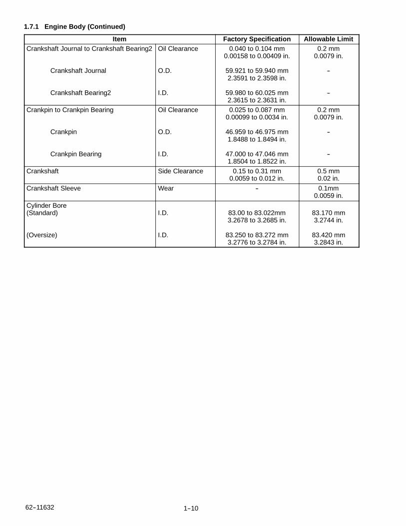
1.7.1 Engine Body (Continued)
Item Factory Specification Allowable LimitCrankshaft Journal to Crankshaft Bearing2
Crankshaft Journal
Crankshaft Bearing2
Oil Clearance
O.D.
I.D.
0.040 to 0.104 mm0.00158 to 0.00409 in.
59.921 to 59.940 mm2.3591 to 2.3598 in.
59.980 to 60.025 mm2.3615 to 2.3631 in.
0.2 mm0.0079 in.
--
--
Crankpin to Crankpin Bearing
Crankpin
Crankpin Bearing
Oil Clearance
O.D.
I.D.
0.025 to 0.087 mm0.00099 to 0.0034 in.
46.959 to 46.975 mm1.8488 to 1.8494 in.
47.000 to 47.046 mm1.8504 to 1.8522 in.
0.2 mm0.0079 in.
--
--
Crankshaft Side Clearance 0.15 to 0.31 mm0.0059 to 0.012 in.
0.5 mm0.02 in.
Crankshaft Sleeve Wear -- 0.1mm0.0059 in.
Cylinder Bore(Standard)
(Oversize)
I.D.
I.D.
83.00 to 83.022mm3.2678 to 3.2685 in.
83.250 to 83.272 mm3.2776 to 3.2784 in.
83.170 mm3.2744 in.
83.420 mm3.2843 in.

1--11 62--11362
1.7.2 Lubricating System
Item Factory Specification Allowable LimitEngine Oil Pressure At Idle Speed
At Rated Speed
More Than 98 kPa1.0 kgf/cm2
14 psi
300 to 440 kPa3.0 to 4.5kgf/cm2
43 to 64 psi
50 kPa0.5 kgf/cm2
7 psi
250 kPa2.5 kgf/cm2
36 psi
Engine Oil Pressure Switch WorkingPressure
50 kPa0.5kgf/cm2
7 psi
--
Inner Rotor to Outer Rotor Clearance 0.03 to 0.14 mm0.0012 to 0.0055 in.
0.2 mm0.008 in.
Outer Rotor to Pump Body Clearance 0.11 to 0.19 mm0.0044 to 0.0074 in.
0.25 mm0.0098 in.
Inner Rotor to Cover Clearance 0.105 to 0.150 mm0.00414 to 0.00590 in.
0.2 mm0.008 in.
1.7.3 Cooling System
Item Factory Specification Allowable LimitV--Belt Tension 7.0 to 9.0 mm (0.28 to
0.35 in.) deflection at98N(10kgf, 22 lbs.)
of force
--
Thermostat Valve OpeningTemperature(At Beginning)
Valve OpeningTemperature(OpenedCompletely)
80.5 to 83.5°C176.9 to 182.3°F
95°C203°F
--
--
1.7.4 Fuel System
Item Factory Specification Allowable LimitInjection Pump Injection Timing 0.0568 to 0.0829 rad.
(3.25 to 4.75°) beforeT.D.C.
--
Pump Element Fuel Tightness -- 18.63 Mpa190.0 kgf/cm2
2702 psiDelivery Valve Fuel Tightness 10 seconds
18.62 to 17.76 Mpa190.0 to 180.0 kgf/cm2
2702 to 2560 psi
5 seconds18.63 to 17.65 Mpa
190.0 to 180.0kgf/cm2
2702 psi to 2560 psi
Injection Nozzle Injection Pressure(1st stage)
18.64 to 20.10 Mpa190.0 to 205.0 kgf/cm2
2703 to 2915 psi
--
Injection Nozzle Valve Seat Valve SeatTightness
When the pressure is16.67 Mpa (170.0 kgf/cm2
2418 psi) the valve seatmust not leak.
--

1--1262--11632
1.7.5 Electrical System
Item Factory Specification Allowable LimitStarter
Commutator
Mica
Brush
Brush Holder and Holder Support
O.D.
Undercut
Length
Resistance
32.0 mm1.26 in.
0.50 mm0.020 in.
0.18 mm0.709 in.
Infinity
31.4 mm1.24 in.
0.20 mm0.0079 in.
11.0 mm0.433 in.
--
Intake Air Heater Resistance (cold) Approx. 0.3 ohm --

1--13 62--11362
1.8 CHECK AND MAINTENANCE
1.8.1 Checking Engine Oil Level
1. Level the engine.
2. To check the oil level, draw out the dipstick (1), wipe itclean, reinsert it, and draw it out again. Check to seethat the oil level lies between the two notches.
3. If the level is too low, add new oil to the specifiedlevel.
NOTE
When adding oil to the crankcase, be sure thatthe fresh oil is the same type and viscosity asthe oil that is already in the crankcase. Nevermix two different types of oil. Never over fill acrankcase.
1.8.2 Checking Coolant Level
1. Remove the radiator cap and check to see that thecoolant level is just below the port.
With the recovery tank: Check to see that the coolantlevel lies between FULL and LOW.
2. If the coolant level is too low, check the reason for thelost coolant.
a. If coolant loss is due to evaporation, add only cleansoft water.
b. If coolant loss is due to a leak, repair the leak, thenadd a coolant mixture of the same type and specifi-cation that is in the system. If the coolant brand can-not be identified, drain out all of the remaining cool-ant and refill with a totally new mix.
CAUTIONDo not remove the radiator cap until thecoolant temperature is below its boilingpoint. Loosen the cap slightly to relieve ex-cess pressure before removing the capcompletely.
NOTE
When adding coolant to the system, air must bevented from the engine coolant passages.Venting air can be accomplished by jiggling theupper and lower radiator hoses.
Be sure to close the radiator cap securely. If thecap is loose or improperly closed, coolant mayleak out and the engine could overheat.
Do not use an antifreeze and scale inhibitor atthe same time.
Never mix different types or brands of coolants.
1.8.3 Checking Fuel Hose
1. If the clamp is loose, apply oil to the threads andsecurely retighten it.
2. The fuel hose is made of rubber and ages regardlessof the service period. Change the hose and clampstogether every two years.
3. Change the fuel hose and clamps whenever any de-terioration or damage is detected.
4. After the fuel hose and clamps have been changed,bleed air out of the fuel system.
CAUTIONStop the engine when attempting to checkand change the fuel line.

1--1462--11632
1.8.4 Bleeding Fuel System1. Open the air vent cock (1) on top of the fuel injection
pump.
2. Loosen the priming pump handle (2), and pump thehandle until bleeding is completed.
3. Depress and twist the priming pump handle clock-wise to lock into place.
4. Close the air vent cock (1).
NOTE
Always keep the air vent cock on the fuel injec-tion pump closed except when bleeding the fuelsystem, or the engine may not run.
1.8.5 Checking V--Belt
Refer to Section 4.1
1.8.6 Changing Engine Oil
CAUTIONStop the engine when preparing to changethe engine oil.
1. After warming up the engine, shut it off.
2. Place a pan underneath the engine.
3. Remove the drain plug, drain the engine oilcompletely.
4. Inspect the drain plug gasket. Replace if necessary.
5. Reinstall the drain plug.
6. Replace the oil filter with a new oil filter.
7. Fill the crankcase with new oil.
8. Check for the correct oil level. (Refer to Section 1.8.1)
NOTE
When changing to a different oil manufactureror viscosity, be sure to remove all of the old oilcompletely. Never mix different types of oil.
Use only API classification CG--4 or better oils.
Use the proper SAE engine oil according to theambient temperatures.
Above 25°C (77°F).............SAE 30 or 10W--3010W--40
0° to 25°C (32° to 77°F)......SAE 20 or 10W--3010W--40
Below 0°C (32°F)............SAE 10W or 10W--30
NOTE
With emission controls now in effect, the CG--4or CH--4 / CI lubricating oils have been devel-oped for use of a low--sulfur fuel on--road ve-hicles engines. When an off--road vehicle en-gine runs on a high--sulfur fuel, it is advisable toemploy the CH--4 / CI lubricating oil with a hightotal base number. If the CG--4 lubricating oil isused with a high sulfur fuel, change the lubricat-ing oil at shorter intervals.
Lubricating oil recommended when a low--sulfur orhigh--sulfur fuel is employed.
Lubricating Oil Class Fuel
Low--sulfur High--sulfur
CG--4 O OCH--4 or CI O X
O : Recommended X : Not Recommended
1--15 62--11362
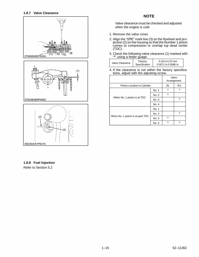
1.8.7 Valve Clearance
1.8.8 Fuel InjectionRefer to Section 5.2
NOTE
Valve clearance must be checked and adjustedwhen the engine is cold.
1. Remove the valve cover.
2. Align the “1TC” mark line (3) on the flywheel and pro-jection (2) on the housing so that the Number 1 pistoncomes to compression or overlap top dead center(TDC).
3. Check the following valve clearance (1) marked with“*” using a feeler guage.
Valve ClearanceFactory
Specification0.18 to 0.22 mm
0.0071 to 0.0086 in.
4. If the clearance is not within the factory specifica-tions, adjust with the adjusting screw.
ValveArrangement
Piston Location in Cylinder IN. EX.
When No. 1 piston is at TDC
No. 1 * *No. 2 *No. 3 *No. 4
When No. 1 piston is at past TDC
No. 1
No. 2 *No. 3 *No. 4 * *

1--1662--11632
1.9 SPECIAL TOOLSAdditional tools may be found in the Carrier Transicold Performance Parts Service Tool Catalog Number62--03213.
1.9.1 Diesel Engine Compression Tester (GlowPlug)
Part No. 07--00179--01 (Assembly)
Application: Use to measure diesel enginecompression and diagnosis formajor overhaul.
1.9.2 Adapter, Injector To Tester Hose
Part No. 07--00484--00Application: Accessory for 07--00179--01
1.9.3 Tester Injector NozzlePart No. 07--00140--00Application: Injector nozzle tester kit used forchecking and adjusting of the fuel injectors in dieselengines.
1.9.4 Replacement Bowl, Tester Injector NozzlePart No. 07--00140--10Application: Accessory for 07--00140--00
1.9.5 Adapter, Injector Line
Part No. 07--00036--00Application: Accessory for 07--00140--00

1--17 62--11362
1.9 SPECIAL TOOLS (Continued)1.9.6 Oil Pressure TesterCode No. 07916--32032Application: Use to measure lubricating oil
pressure.
1. Guage
2. Adapter 2
3. Cable
4. Adapter 3
5. Threaded Joint
6. Adapter 4
7. Adaptor 1
8. Adaptor 3
1.9.7 Auxiliary Socket For Fixing CrankshaftSleeve
Code No. 07916--32091Application: Use to fix the crankshaft sleeve of the
diesel engine.
1.9.8 Gauge, Belt TensionPart No. 07--00203--00Application: Used to adjust belt tension of all
cogged V--belts.
1.9.9 Tester, Belt Tension
Part No. 07--00253--00Application: Used to test belt tension.
1.9.10 Rubber BandPart No. 07--00253--01Application: Replacement part for belt tension
tester (Part No. 07--00253--00)
1.9.11 Main Bearing Install Tool
Part No. 07--00472--00Application: Used on engines starting with
S/N 3S0001
1.9.12 Main Bearing Extract ToolPart No. 07--00473--00Application: Used on engines starting with
S/N 3S0001

1--1862--11632
1.9 SPECIAL TOOLS (Continued)The following are drawings for special tools that may need to be fabricated.
1.9.13 Valve Guide Replacing ToolApplication: Use to press out and press fit the valve
guide.A 20 mm dia. (0.79 in. dia.)
B 11.7 to 11.9 mm dia. (0.460 to 0.468 in. dia.)
C 6.5 to 6.6 mm dia. (0.256 to 0.259 in. dia.)
D 225 mm (8.86 in.)
E 70 mm (2.76 in.)
F 45 mm (1.77 in.)
G 25 mm (0.98 in.)
H 5 mm (0.197 in.)
I 6.7 to 7.0 mm dia. (0.263 to 0.275 in. dia.)
J 20 mm dia. (0.787 in. dia.)
K 12.5 to 12.8 mm dia. (0.492 to 0.504 in. dia.)
L 8.9 to 9.1 mm (0.350 to 0.358 in.)
C1 Chamfer 1.0 mm (0.039in.)
C2 Chamfer 2.0 mm (0.079in.)
C0.3 Chamfer 0.3 mm (0.012in.)
1.9.14 Bushing Replacing Tools
Application: Use to press out and press fit the bushing.
1. For small end bushing.A 162 mm (6.38 in.)
B 35 mm (1.38 in.)
C 27 mm (1.06 in.)
D 35 mm dia. (1.38 in. dia.)
E 27.90 to 27.95 mm dia. (1.098 to 1.100 in. dia.)
F 25.00 to 25.01 mm dia. (0984 to 0.985 in. dia.)
2. For idle gear bushing.A 175 mm (6.89 in.)
B 40 mm (1.57 in.)
C 38 mm (1.49 in.)
D 45 mm (1.77 in.)
E 41.90 to 41.95 mm dia. (1.650 to 1.652 in. dia.)
F 37.95 to 37.97 mm dia. (1.494 to 1.495 in. dia.)
1.9.15 Flywheel Stopper
Application: Use to loosen and tighten the flywheelscrew.
A 200 mm (7.87 in.)
B 20 mm (0.79 in.)
C 30 mm (1.18 in.)
D 8 mm (0.31 in.)
E 10 mm (0.39 in.)

1--19 62--11362
1.9 SPECIAL TOOLS (Continued)1.9.16 Crankshaft Bearing 1 Replacing ToolApplication: Use to press out and press fit thecrankshaft
bearing No. 1
1. Extracting toolA 130 mm (5.31 in.)
B 72 mm (2.83 in.)
C R40 mm (R1.57 in.)
D 10 mm (0.39 in.)
E 20 mm (0.79 in.)
F 20 mm dia. (0.79 in. dia.)
G 64.8 to 64.9 mm dia. (2.551 to 2.555 in. dia.)
H 59.8 to 59.9 mm dia. (2.354 to 2.358 in. dia.)
2. Extracting toolA 130 mm (5.31 in.)
B 72 mm (2.83 in.)
C R40 mm (R1.57 in.)
D 10 mm (0.39 in.)
E 20 mm (0.79 in.)
F 20 mm (0.79 in.)
G 20 mm dia. (0.79 in. dia.)
H 68 mm dia. (2.68 in. dia.)
I 59.8 to 59.9 mm dia. (2.354 to 2.358 in. dia.)
J 64.8 to 64.9 mm dia. (2.551 to 2.555 in. dia.)

2--1 62--11362
SECTION 2
ENGINE BODY
2.1 CHECKING AND ADJUSTING2.1.1 Compression Pressure
1. Run the engine until it is warmed up.
2. Stop the engine and disconnect the 2P connectorfrom the stop solenoid to prevent fuel delivery to theengine.
3. Remove the the air cleaner, the muffler and all the in-jection nozzles.
4. Install a compression tester with the adapter in one ofthe nozzle hole.
5. While cranking the engine with the starter measurethe compression pressure.
6. Repeat steps 4 and 5 for each cylinder.
7. If the measurement is below the allowable limit, add asmall amount of oil to the cylinder thru the nozzle holeand measure the compression again.
a. If the compression pressure is still less than the al-lowable limit, check the top clearance, valves andcylinder head.
b. If the compression pressure increases after applyingoil, check the cylinder wall and piston rings.
NOTE
Check the compression pressure with the spe-cified valve clearance
Always use a fully charged battery for perform-ing this test.
Variances in cylinder compression valuesshould be under 10%.
Compression Pres-sure
FactorySpecification
2.95 to 3.23 MPa30 to 33 kgt/cm2
427 to 469 psi
Allowable Limit2.35 MPa24 kgt/cm2
341 psi
2.1.2 Top Clearance
1. Piston 2 Plastic gauge
1. Remove the valve cover. (Refer to Section 2.2.3.a)
2. Remove the cylinder head.
3. Move the piston (1) up and stick a strip of plasticgauge (2) on the piston head at three positions shownon the illustration.
4. Lower the piston and install the cylinder head. (Use anew cylinder head gasket and tighten the cylinderhead bolts to the proper torque.
5. Turn the flywheel until the piston (1) passes throughtop dead center.
6. Remove the cylinder head and measure the plasticgauge.
7. If the measurement is not within the factory specifica-tions, check the clearances between the crank pinand bearing and between the piston pin and bushing.
Top ClearanceFactory
Specification0.60 to 0.70 mm0.024 to 0.027 in.
TighteningTorque
Cylinder HeadBolts
93.2 to 98.0 N.m9.5 to 10.0 kgf.m68.8 to 72.3 ft--lbs
2--262--11362
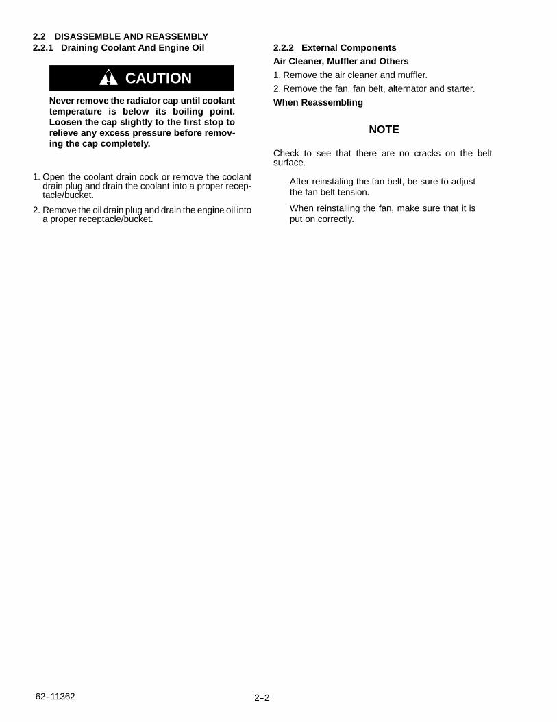
2.2 DISASSEMBLE AND REASSEMBLY2.2.1 Draining Coolant And Engine Oil
CAUTIONNever remove the radiator cap until coolanttemperature is below its boiling point.Loosen the cap slightly to the first stop torelieve any excess pressure before remov-ing the cap completely.
1. Open the coolant drain cock or remove the coolantdrain plug and drain the coolant into a proper recep-tacle/bucket.
2. Remove the oil drain plug and drain the engine oil intoa proper receptacle/bucket.
2.2.2 External ComponentsAir Cleaner, Muffler and Others
1. Remove the air cleaner and muffler.
2. Remove the fan, fan belt, alternator and starter.
When Reassembling
NOTE
Check to see that there are no cracks on the beltsurface.
After reinstaling the fan belt, be sure to adjustthe fan belt tension.
When reinstalling the fan, make sure that it isput on correctly.

2--3 62--11362
2.2.3 Cylinder Head And Valves2.2.3.a Valve Cover
1. Remove the breather hose (2).
2. Remove the valve cover bolts (1).
3. Remove the valve cover (3).
When Reassembling
Check to see that the valve cover gasket (4) is in goodcondition and in place.
TighteningTorque
Valve CoverBolts
6.87 to 11.2 N.m0.7 to 1.15 kgf.m5.07 to 8.31 ft--lbs
1. Valve Cover Bolt
2. Breather Hose
3. Valve Cover
4. Valve Cover Gasket
5. Breather Valve
6. Plate
2.2.3.b Injection Pipes
1. Loosen the bolts on the pipe clamps (1).
2. Detach the injection pipes (2).
When Reassembling
Blow out any debris that may be in the pipes.
TighteningTorque
Injection PipeRetaining
Nut
15 to 24 N.m1.5 to 2.5 kgf.m11 to 18 ft--lbs

2--462--11362
2.2.3 Cylinder Head And Valves (Continued)
3
4
1. Rocker Arm Bracket
Mounting Bolt
2. Rocker Arm Assembly
3. Push Rod
4. Tappet
2.2.3.c Nozzle Holder Assembly
1. Remove the overflow pipe assembly.
2. Remove the nozzle holder assemblies (1).
When Reassembling
Replace the copper gasket with a new one.
TighteningTorque
Nozzle HolderAssembly
26 to 29 N.m2.6 to 3.0 kgf.m19 to 21 ft--lbs
Overflow PipeAssembly
Retaining Bolt
9.81 to 11.2 N.m1.00 to 1.15 kgf.m7.24 to 8.31 ft--lbs
2.2.3.d Rocker Arm and Push Rod
1. Remove the rocker arm bracket mounting bolts (1).
2. Detach the rocker arm assembly (2).
3. Remove the push rods (3).
When Reassembling
When putting the push rods (3) onto the tappets (4),check to see if the push rod end is properly seated in thetappet dimples.
NOTE
After instaling the rocker arm, be sure to adjustthe valve clearance. (Refer to Section 1.8.7)
TighteningTorque
Rocker ArmBracket Mounting
Bolt
24 to 27 N.m2.4 to 2.8 kgf.m18 to 20 ft--lbs

2--5 62--11362
2.2.3 Cylinder Head And Valves (Continued)
1
2 3
4513 12
168917
11157
610
1418
1. Hose Clamp
2. Filter--Drier Inlet
A: Gear Case Side
B: Flywheel Side
2.2.3.e Cylinder Head1. Loosen the hose clamp (1), and remove the water re-
turn pipe (2).2. Remove the cylinder head bolts in the order of (18) to
(1).3. Lift up the cylinder head and remove.4. Remove the cylinder head gasket (3).When ReassemblingReplace the cylinder head gasket (3) with a new one.Apply oil to, then re--install the cylinder head bolts.Tighten the cylinder head bolts in sequence startingfrom the center in the order of (1) to (18).Tighten the head bolts uniformly or head warpage mayoccur.
TighteningTorque
Cylinder HeadBolt
93.1 to 98.0 N.m9.5 to 10.0 kgf.m68.7 to 72.3 ft--lbs
NOTE
When replacing the cylinder head gasket (3), besure you are using a new gasket that matchesthe original gasket.
2.2.3.f Tappets1. Remove the tappets (1) from the crankcase.When ReassemblingVisually check the contact between the tappets (1) andindividual cam lobes.Coat the tappets with engine oil before installing them.
NOTE
When re--installing tappets into the engine,make sure that they are re--installed in their ori-ginal location.
2.2.3.g Valves1. Remove the valve caps (3).2. Remove the valve spring collet (4), pushing the valve
spring retainer (5) by the valve spring compressor (1).3. Remove the valve spring retainer (5), valve spring (6)
and valve stem seal (2).4. Remove the valve (7).When ReassemblingClean the valve stem and the valve guide. Apply engineoil to the valve stem when reassembling.After installing the valve spring collets (4), lightly tap thestem with a plastic hammer to assure the collets haveseated on the valve stem.
NOTE
When re--installing valves into the engine,make sure that they are re--installed in theiroriginal location.

2--662--11362
2.2.4 Injection Pump and Gear Case2.2.4.a Injection Pump
1. Remove the fuel speed solenoid (2) and hi--idlingbody (3).
2. Remove the engine stop lever (5) and stop solenoidguide (6).
3. Remove the fuel injection pump assembly (7).
NOTE
Remove the injection pump assembly (7) afterremoving the fuel speed solenoid (2) and hi--id-ling body (3), engine stop lever (5) and stopsolenoid guide (6).
When Reassembling
Install the fuel speed solenoid (2), the hi--idling body (3)and the stop solenoid guide (6) after Installing theinjection pump (7).
Replace the hi--idling body gasket (4) with a new one.
Install the fuel speed solenoid guide (6) and then thestop lever (5) into the gear case. Cycle the stop lever toinsure that it functions.
NOTE
When installing the fuel speed solenoid (2), usecare to keep the O--ring (1) in place.
Be sure to insert the push rod of the stop solenoid intothe hole at the center of the solenoid guide (6).
TighteningTorque
Hi--idling Body45.0 to 49.0 N.m4.5 to 5.0 kgf.m33 to 36 ft--lbs
1. O--ring
2. Fuel Speed Solenoid
3. Hi--Idling Body
4. Hi--Idling Body Gasket
5. Stop Lever
6. Stop Solenoid Guide
7. Injection Pump Assembly

2--7 62--11362
2.2.4 Injection Pump and Gear Case (Continued)2.2.4.b Governor Springs and Speed Control Plate
NOTE
Specific Tool (1): A 1.2mm (.050 inch) diameterwire with a total length of 200mm (8 inch) withthe tip bent into a hook as depicted in theillustration is required to hang the governorsprings.
1. Remove the injection pump cover.
2. Remove the speed control plate (7) mounting nuts (3)and bolts (4).
3. Using the Specific Tool (1), undo the the largegovernor spring (5) from the fork lever (2).
4. Set the speed control lever (6) as shown in the figure.
5. Remove the speed control plate (7), using care not tolet the governor spring (5) disengage from the plateand fall into the gear case.
1. Specific Tool
2. Fork Lever
3. Speed Control Plate
Mounting Nut
4. Speed Control Plate
Mounting Bolt
5. Large Governor Spring
6. Speed Control Lever
7. Speed Control Plate

2--862--11362
2.2.4 Injection Pump and Gear Case (Continued)2.2.4.b Governor Springs and Speed Control Plate
(Continued)
When Reassembling
NOTE
A length of string passed thru the governorspring can be used to retrieve the spring if it un-hooks from both the specific tool and the speedcontrol plate.
Begin reassembly by inserting the specific tool (1) thruthe injection pump cover opening thru to the speedcontrol plate opening.
1. Using the specific tool (1), capture the governorspring (5) and speed control plate (7) assembly.
2. Pull the governor spring (5) / speed control plate (7)assembly thru and secure it to the fork lever (2).
3. Seat and assemble the speed control (5) plate withtwo bolts and two nuts to the gear case.
4. Check the movement of the speed control lever (4).
NOTE
The speed control lever (6) must be free tomove from low idle position to maximum speedposition and should always return to the highidle position.
5. Finally, install the injection pump cover to the gearcase.
1. Specific Tool
2. Fork Lever
3. Speed Control Plate
Mounting Nut
4. Speed Control Plate
Mounting Bolt
5. Large Governor Spring
6. Speed Control Lever
7. Speed Control Plate

2--9 62--11362
2.2.4 Injection Pump and Gear Case (Continued)
1. Nut
2. Fan Drive Pulley
3. 46 mm Deep Socket wrench
4. Gear Puller
1. Gear Case
2. Gear Case Gasket
3. O--ring
4. O--ring
5. Oil seal
2.2.4.c Fan Drive Pulley
1. Lock the flywheel using the flywheel stopper
2. Remove the fan drive pulley mounting nut (1) usingthe 46 mm deep socket wrench (3).
3. Remove the fan drive pulley (2) with a gear puller (4).
4. Remove the feather key.
When Reassembling
Apply grease to the splines of the coupling.
TighteningTorque
Drive PulleyMounting Nut
138 to 156 N.m14.0 to 16.0 kgf.m102 to 115 ft--lbs
2.2.4.d Gear Case
1. Remove the gear case (1).
2. Remove the O--rings (3)(4).
When Reassembling
Replace the gear case gasket and O--rings (3)(4).
Apply gasket sealant to both sides of the gear casegasket (2).
Check/insure that the four O--rings (3)(4) are in place onthe gear case (1).
Apply a thin film of oil to the crankshaft oil seal lip (5) andtake care not to roll the lip when installing the gear case.
2--1062--11362
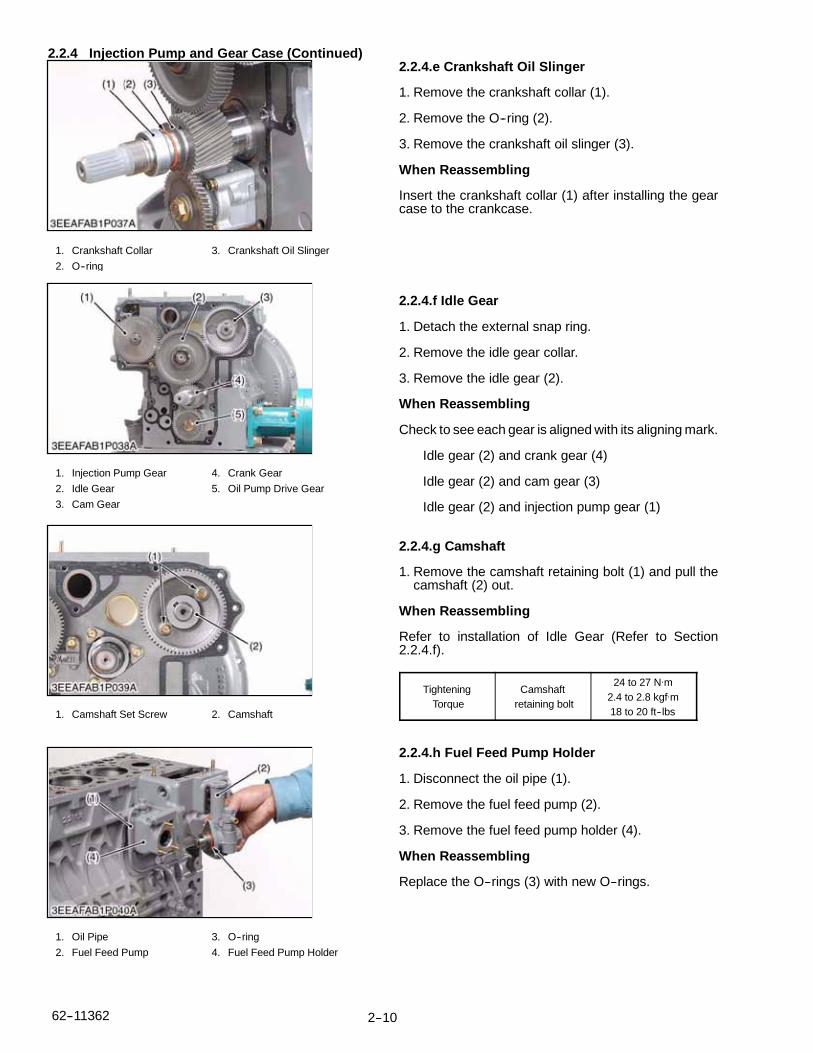
2.2.4 Injection Pump and Gear Case (Continued)
1. Crankshaft Collar
2. O--ring
3. Crankshaft Oil Slinger
1. Injection Pump Gear
2. Idle Gear
3. Cam Gear
4. Crank Gear
5. Oil Pump Drive Gear
1. Camshaft Set Screw 2. Camshaft
1. Oil Pipe
2. Fuel Feed Pump
3. O--ring
4. Fuel Feed Pump Holder
2.2.4.e Crankshaft Oil Slinger
1. Remove the crankshaft collar (1).
2. Remove the O--ring (2).
3. Remove the crankshaft oil slinger (3).
When Reassembling
Insert the crankshaft collar (1) after installing the gearcase to the crankcase.
2.2.4.f Idle Gear
1. Detach the external snap ring.
2. Remove the idle gear collar.
3. Remove the idle gear (2).
When Reassembling
Check to see each gear is aligned with its aligning mark.
Idle gear (2) and crank gear (4)
Idle gear (2) and cam gear (3)
Idle gear (2) and injection pump gear (1)
2.2.4.g Camshaft
1. Remove the camshaft retaining bolt (1) and pull thecamshaft (2) out.
When Reassembling
Refer to installation of Idle Gear (Refer to Section2.2.4.f).
TighteningTorque
Camshaftretaining bolt
24 to 27 N.m2.4 to 2.8 kgf.m18 to 20 ft--lbs
2.2.4.h Fuel Feed Pump Holder
1. Disconnect the oil pipe (1).
2. Remove the fuel feed pump (2).
3. Remove the fuel feed pump holder (4).
When Reassembling
Replace the O--rings (3) with new O--rings.

2--11 62--11362
2.2.4 Injection Pump and Gear Case (Continued)
1. Fuel Camshaft Stopper
2. Fork Lever Holder Mounting
Screws
3. Fork Lever 1
4. Fork Lever 2
5. Injection Pump Gear
6. Fuel Camshaft
7. Fork Lever Holder
1. Oil Pump2. Oil Pump Drive Gear
3 Gear Puller
2.2.4.i Fuel Camshaft And Fork Lever Assembly
1. Detach the fuel camshaft stopper (1).
2. Remove the three fork lever holder mounting screws(2).
3. Remove the fuel camshaft assembly (5), (6) and forklever assembly (3), (4), and (7) at the same time.
When Reassembling
After installation, check to see that the fork levers 1 (3)and 2 (4) are fixed to the fork lever shaft, and that theycan turn smoothly in the holder (7).
2.2.4.j Oil Pump
1. Remove the nut.
2. Draw out the oil pump drive gear (2) with a gear puller(3).
3. Remove the four oil pump mounting bolts. Detach theoil pump (1).
2--1262--11362
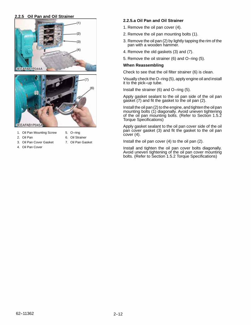
2.2.5 Oil Pan and Oil Strainer
(7)
1. Oil Pan Mounting Screw
2. Oil Pan
3. Oil Pan Cover Gasket
4. Oil Pan Cover
5. O--ring
6. Oil Strainer
7. Oil Pan Gasket
2.2.5.a Oil Pan and Oil Strainer
1. Remove the oil pan cover (4).
2. Remove the oil pan mounting bolts (1).
3. Remove the oil pan (2) by lightly tapping the rim of thepan with a wooden hammer.
4. Remove the old gaskets (3) and (7).
5. Remove the oil strainer (6) and O--ring (5).
When Reassembling
Check to see that the oil filter strainer (6) is clean.
Visually check the O--ring (5), apply engine oil and installit to the pick--up tube.
Install the strainer (6) and O--ring (5).
Apply gasket sealant to the oil pan side of the oil pangasket (7) and fit the gasket to the oil pan (2).
Install the oil pan (2) to the engine, and tighten the oil panmounting bolts (1) diagonally. Avoid uneven tighteningof the oil pan mounting bolts. (Refer to Section 1.5.2Torque Specifications)
Apply gasket sealant to the oil pan cover side of the oilpan cover gasket (3) and fit the gasket to the oil pancover (4).
Install the oil pan cover (4) to the oil pan (2).
Install and tighten the oil pan cover bolts diagonally.Avoid uneven tightening of the oil pan cover mountingbolts. (Refer to Section 1.5.2 Torque Specifications)

2--13 62--11362
2.2.6 Piston and Connecting Rod
6
2.2.6.a Pistons1. Completely remove the carbon ridge (1) at the top of
the cylinder walls.2. Remove the connecting rod cap (3).3. Turn the flywheel and bring the piston to top dead
center.4. Push the piston out by lightly tapping the connecting
rod from the bottom of the crankcase with the grip of ahammer.
5. Repeat the procedure for the other three cylinders.When ReassemblingLiberally coat the piston and piston rings with engine oil.When inserting the piston into the cylinder, face themark on the connecting rod to the injection pump.
NOTE
If re--installing the original piston assembliesinto the engine be sure that they are returned totheir original cylinder.
Place the piston rings with their gaps at 2.09rad. (120°) from the piston pin’s direction asshown.
Carefully insert the pistons into the cylindersusing the piston ring compressor (7).
When inserting the piston into the cylinder avoiddamaging the molybdenum disulfide coating onthe piston skirt. This coating is useful in mini-mizing the clearance between the piston andcylinder.
When replacing a piston, use a replacementpiston with the same code number. The pistonID mark (6) is on top of the piston.
1. Carbon
2. Connecting Rod Bolt
3. Connecting Rod Cap
4. Connecting Rod
5. Molybdenum Disulfide
Coating on Piston Skirt
6. Piston ID Mark
7. Piston Ring Compressor
(A) Top Ring Gap
(B) Second Ring Gap
(C) Oil Ring Gap
(D) Piston Pin Hole
(a) 2.09 rad. (120°)
TighteningTorque
ConnectingRod Bolt
45 to 49 N.m4.5 to 5.0 kgf.m33 to 36 ft--lbs

2--1462--11362
2.2.6 Piston and Connecting Rod (Continued)
7
8
7
2.2.6.b Piston Ring and Connecting Rod1. Remove the piston rings (1), (2), (3).2. Remove the piston pin (8) and then seperate the con-
necting rod (6) from the piston (5).
NOTE
Mark both the connecting rod and piston so thatif they are to be re--used that the original com-bination of parts will go back together. Do not in-terchange used parts.
When ReassemblingWhen installing the rings, assemble so that themanufacturer’s mark (12) near the gap faces the top ofthe piston (5).When installing the oil control ring (3) onto the piston (5),place the expander joint (10) on the opposite side of theoil ring gap (11).Apply engine oil to the piston pin (8).When assembling the connecting rod (6) to the piston(5), immerse the piston (5) in hot oil (80°C / 176°F) for 10to 15 minutes, then assemble the piston, piston pin, andconnecting rod.
NOTE
Assemble the piston (5) on to the connectingrod (6) with the FW mark (9) facing the flywheelend and the connecting rod mark (7) facing theinjection pump side.
1. Top Ring
2. Second Ring
3. Oil Control Ring
4. Piston Pin Snap Ring
5. Piston
6. Connecting Rod
7. Mark
8. Piston Pin
9. FW Mark
10. Expander Joint
11. Oil Ring Gap
12. Manufacturer’s Mark

2--15 62--11362
2.2.7 Crankshaft
1. Flywheel
2. Flywheel Bolt
3. Flywheel Guide Bolts
1. Bearing Case Cover
Mounting Bolt
2. Bearing Case Cover
Mounting bolt
3. Bearing Case Cover
4. Oil Seal
5. Bearing Case Gasket
6. Bearing Case Cover
Gasket
(a). Top
2.2.7.a Flywheel1. Prevent the flywheel (1) from rotating.2. Remove two flywheel bolts (2).
NOTE
The use of air tools to remove the flywheel boltsmay damage the threads in the crankshaft.
3. Install two flywheel guide bolts (3).4. Remove all of the flywheel bolts (2).5. Remove the flywheel (1) slowly along the flywheel
guide bolts (3).When ReassemblingInstall two flywheel guide bolts (3).Check to see that the mating surfaces of the crankshaftand flywheel are clean.Apply engine oil to the flywheel bolts and install.
TighteningTorque
Flywheel Bolts98.0 to 107.8 N.m10.0 to 11.0 kgf.m72.3 to 79.5 ft--lbs
2.2.7.b Bearing Case Cover1. Remove the bearing case cover mounting bolts. First,
remove the inside bolts (2) and then the outside bolts(1).
2. Screw two of the removed bolts into the bolt hole ofthe bearing case cover (3) to remove it.
NOTE
The length of the inside (2) and the outside (1)bolts is different. When reassembling reinstallthe appropriate bolt in the correct location.
When ReassemblingFit the bearing case gasket (5) and the bearing casecover gasket (6) to the bearing case cover (3). Orientthem correctly.Install the bearing case cover (3), again orienting itcorrectly, using the “UP” mark (a).Apply oil to the oil seal (4), and take care not to roll theseal when installed.Tighten the bearing case cover bolts diagonally andevenly.
TighteningTorque
Bearing CaseCover Mounting
bolt
24 to 27 N.m2.4 to 2.8 kgf.m18 to 20 ft--lbs

2--1662--11362
2.2.7 Crankshaft (Continued)2.2.7.c Crankshaft Assembly Removal
NOTE
Before disassembling, check the sideclearance of the crankshaft. Check itduring reassembly.
1. Remove the three main bearing case bolts (1).
2. Pull out the crankshaft assembly (2), being carefulnotto damage the crankcase bearings (3).
3. While pulling the crankshaft assembly (2) out, usecare to align each of the crank pins (5) (left or right) toclear the crankcase relief (a).
When ReassemblingWhen installing the main bearing case assembly, alignthe bolt holes of the crankshaft assembly (2) with theholes of the crankcase.
Apply oil to the threads of the main bearingcase bolts (1)before re--insertion.
TighteningTorque
Main BearingCase Bolt
69 to 73 N.m7.0 to 7.5 kgf.m51 to 54 ft--lbs
1. Main Bearing Case Screw 2
2. Main Bearing Case 2
3. Crankshaft Bearing 1
4. Crankshaft Assembly
5. Cylinder 4 Crank Pin
(a).Main Bearing Case Relief

2--17 62--11362
2.2.7 Crankshaft (Continued)
7
8
8
2.2.7.d Main Bearing Case Assembly1. Remove the two main bearing case bolts (7), and re-
move the main bearing case assembly being carefulwith the thrust bearing and crankshaft bearing.
2. Remove the remaining main bearing cases as above.
When Reassembling
Clean the oil passages in the main bearing case.
Apply clean engine oil to the bearings.
Install the main bearing case assemblies in their originallocations. The diameters of the main bearing casesvary. Install them in order from the gear case endaccording to their markings (A,B,C).
Match the alignment numbers (1) and mark (2) on themain bearing case.
When installing the main bearing case, face the mark“FLYWHEEL” to the flywheel.
Install the thrust bearing with its oil groove facing (8)outward.
Confirm that main bearing case moves smoothly aftertorquing the main bearing case bolt to specification.
TighteningTorque
Main BearingCase bolt
46 to 50 N.m4.7 to 5.2 kgf.m34 to 37 ft--lbs
1. Alignment Number
2. Alignment Mark
3. No Mark
4. C
5. B
6. A
7. Main bearing Case Bolt
8. Oil Groove
2--1862--11362
2.3 SERVICING
2.3.1 Cylinder Head And Valves
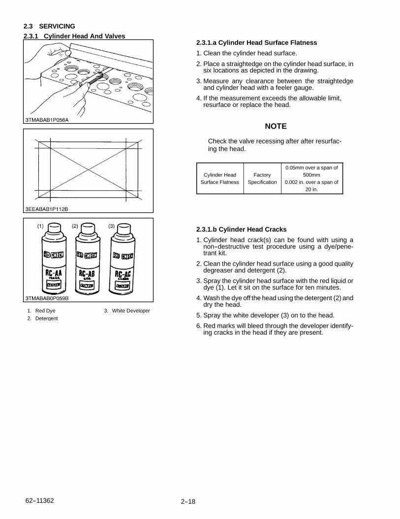
1. Red Dye
2. Detergent
3. White Developer
2.3.1.a Cylinder Head Surface Flatness
1. Clean the cylinder head surface.
2. Place a straightedge on the cylinder head surface, insix locations as depicted in the drawing.
3. Measure any clearance between the straightedgeand cylinder head with a feeler gauge.
4. If the measurement exceeds the allowable limit,resurface or replace the head.
NOTE
Check the valve recessing after after resurfac-ing the head.
Cylinder HeadSurface Flatness
FactorySpecification
0.05mm over a span of500mm
0.002 in. over a span of20 in.
2.3.1.b Cylinder Head Cracks
1. Cylinder head crack(s) can be found with using anon--destructive test procedure using a dye/pene-trant kit.
2. Clean the cylinder head surface using a good qualitydegreaser and detergent (2).
3. Spray the cylinder head surface with the red liquid ordye (1). Let it sit on the surface for ten minutes.
4. Wash the dye off the head using the detergent (2) anddry the head.
5. Spray the white developer (3) on to the head.
6. Red marks will bleed through the developer identify-ing cracks in the head if they are present.

2--19 62--11362
2.3.1 Cylinder Head And Valves (Continued)
1. Cylinder Head
Surface
(A) Recess
(B) Protrusion
2.3.1.c Valve Recessing
1. Clean the cylinder head surface (1), valve face andvalve seat.
2. Insert the valve into the head, making certain that thevalve is fully seated.
3. Measure the valve recessing with a depth gauge.
4. If the measurement exceeds the allowable limit, re-place the valve.
5. If the measurement still exceeds the allowable limit,replace the cylinder head.
ValveRecessing
FactorySpecification
0.065 (protrusion) mm to0.085 (recessing) mm0.026 (protrusion) in. to0.033 (recessing) in.
Allowable Limit --
2.3.1.d Clearance Between Valve Stem And ValveGuide
1. Remove carbon from the valve guide section.
2. Measure the valve stem O.D. with a micrometer.
3. Measure the valve guide with a small hole gauge, andcalculate the clearance.
4. If the clearance exceeds the the allowable limit, re-place the valves. If the clearance still exceeds the al-lowable limit, replace the valve guide.
ClearanceBetween
Valve Stemand Guide
FactorySpecification
0.040 to 0.070 mm0.0016 to 0.0027 in.
Allowable Limit0.1 mm0.0039 in.
Valve StemO.D.
FactorySpecification
7.960 to 7.975 mm0.3134 to 0.3139 in.
Valve GuideI.D.
FactorySpecification
8.015 to 8.030 mm0.3156 to 0.3161 in.

2--2062--11362
2.3.1 Cylinder Head And Valves (Continued)
(A) When Removing (B) When Installing
1. Correct
2. Incorrect
3. Incorrect
2.3.1.e Replacing Valve Guide(A) (When removing)
1. Press out the used valve guide using a valve guide re-placing tool.
(B) (When installing)1. Clean a new valve guide and valve guide bore, then
apply oil to them.
2. Press in a new valve guide using a valve guide replac-ing tool.
3. Ream the I.D. of the valve guide to the specified di-mension (precisely).
Valve Guide I.D.Intake & Exhaust
FactorySpecification
8.015 to 8.030 mm0.3156 to 0.3161 in.
2.3.1.f Valve Seating1. Coat the valve face lightly with prussian blue and put
the valve on its seat to check the contact pattern
2. If the valve does not seat all the way around the valveseat, or the contact is less than 70%, correct the valveseating as outlined in paragraph 2.3.1.g.
3. If the valve contact does not comply with the refer-ence value, replace the valve or correct the contact ofvalve seating.

2--21 62--11362
2.3.1 Cylinder Head And Valves (Continued)
a b
(1) (2)
a. 0.26 rad.(15°) or
0.52 rad.(30°)
b. 0.79 rad.(45°) or
1.0 rad.(60°)
c. 0.52 rad.(30°) or
0.26 rad.(15°)
A. Check Contact
B. Correct Seat Width
C Check Contact
1. Valve Seat Width
2 . Identical Dimensions
2.3.1.g Correcting Valve and Valve Seat
NOTE
Before correcting the valve seat, make certainthat the valve and valve guide are within factoryspecifications.
After correcting the valve seat, be sure to checkthe valve recessing.
(A) Correcting the Valve
1. Correct the valve with a valve grinder.
Valve Face AngleFactory
Specification
IN. 0.79 rad / 45°
EX. 0.79 rad / 45°
(B) Correcting the Valve Seat
1. Slightly correct the valve seat surface with a 1.0 rad.(60°) (intake valve) or 0.79 rad. (45°) (exhaust valve)seat cutter.
2. Resurface the seat surface with a 0.52 rad. (30°)valve seat cutter to the Intake valve seat and with a0.26 rad. (15°) valve seat cutter to the exhaust valveseat so that the width is close to the specified valveseat width (2.12 mm, 0.0835 in.).
3. After resurfacing the seat, apply a thin film of valvelapping compound between the valve and the seat,then use a valve lapping tool to seat the valve to thevalve seat.
4. Check the valve seating with prussian blue. The valveseating should show good contact all the way around.
Valve Face AngleFactory
Specification
IN. 0.79 rad / 45°
EX. 0.79 rad / 45°
2.3.1.h Valve Lapping
1. Apply compound evenly to the valve lapping surface.
2. Insert the valve into the valve guide. Lap the valveonto its seat with a valve lapper or bolt driver.
3. After lapping the valve, wash the compound awayand apply oil, then repeat valve lapping with oil.
4. Apply prussian blue to the contact surface to checkthe contact pattern, if it is less than 70%, repeat valvelapping again.
NOTE
When valve lapping is performed, be sure tocheck the valve recessing and adjust the valveclearance after assembling the valve.
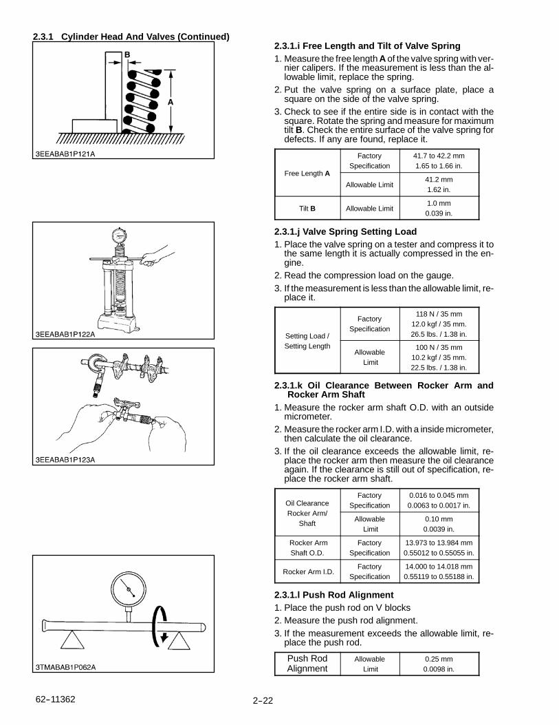
2--2262--11362
2.3.1 Cylinder Head And Valves (Continued)2.3.1.i Free Length and Tilt of Valve Spring1. Measure the free length A of the valve spring with ver-
nier calipers. If the measurement is less than the al-lowable limit, replace the spring.
2. Put the valve spring on a surface plate, place asquare on the side of the valve spring.
3. Check to see if the entire side is in contact with thesquare. Rotate the spring and measure for maximumtilt B. Check the entire surface of the valve spring fordefects. If any are found, replace it.
Free Length A
FactorySpecification
41.7 to 42.2 mm1.65 to 1.66 in.
Allowable Limit41.2 mm1.62 in.
Tilt B Allowable Limit1.0 mm0.039 in.
2.3.1.j Valve Spring Setting Load1. Place the valve spring on a tester and compress it to
the same length it is actually compressed in the en-gine.
2. Read the compression load on the gauge.3. If the measurement is less than the allowable limit, re-
place it.
Setting Load /Setting Length
FactorySpecification
118 N / 35 mm12.0 kgf / 35 mm.26.5 lbs. / 1.38 in.
AllowableLimit
100 N / 35 mm10.2 kgf / 35 mm.22.5 lbs. / 1.38 in.
2.3.1.k Oil Clearance Between Rocker Arm andRocker Arm Shaft
1. Measure the rocker arm shaft O.D. with an outsidemicrometer.
2. Measure the rocker arm I.D. with a inside micrometer,then calculate the oil clearance.
3. If the oil clearance exceeds the allowable limit, re-place the rocker arm then measure the oil clearanceagain. If the clearance is still out of specification, re-place the rocker arm shaft.
Oil ClearanceRocker Arm/
Shaft
FactorySpecification
0.016 to 0.045 mm0.0063 to 0.0017 in.
AllowableLimit
0.10 mm0.0039 in.
Rocker ArmShaft O.D.
FactorySpecification
13.973 to 13.984 mm0.55012 to 0.55055 in.
Rocker Arm I.D.Factory
Specification14.000 to 14.018 mm0.55119 to 0.55188 in.
2.3.1.l Push Rod Alignment1. Place the push rod on V blocks2. Measure the push rod alignment.3. If the measurement exceeds the allowable limit, re-
place the push rod.
Push RodAlignment
AllowableLimit
0.25 mm0.0098 in.

2--23 62--11362
2.3.1 Cylinder Head And Valves (Continued)2.3.1.m Oil Clearance Between Tappet and Tappet
Guide Bore1. Measure the tappet O.D. with a micrometer.2. Measure the I.D. of the tappet guide bore with a cylin-
der gauge and calculate the clearance.3. If the measurement exceeds the allowable limit, or
the tappet is damaged, replace the tappet.
Oil ClearanceTappet/
Tappet GuideBore
FactorySpecification
0.020 to 0.062 mm0.00079 to 0.00244 in.
AllowableLimit
0.07 mm0.003 in.
Tappet O.D.Factory
Specification23.959 to 23.980 mm0.94327 to 0.94409 in.
Tappet Guide I.D.Factory
Specification24.000 to 24.021 mm0.94489 to 0.94570 in.
2.3.2 Timing Gears, Camshaft and Fuel Camshaft2.3.2.a Timing Gear Backlash
1. Set a dial indicator (lever type) with its tip on the geartooth.
2. Move the gear to measure the backlash, holding itsmating gear.
3. If the backlash exceeds the allowable limit, check theoil clearance of the shafts and the gear.
4. If the oil clearance is proper, replace the gear.
Backlash/Idle Gear/
Crank Gear
FactorySpecification
0.0415 to 0.1122 mm0.00163 to 0.00442 in.
AllowableLimit
0.15 mm0.0059 in.
Backlash/Idle Gear/Cam Gear
FactorySpecification
0.0415 to 0.1154 mm0.00163 to 0.00454 in.
AllowableLimit
0.15 mm0.0059 in.
Backlash/Idle Gear/
Injection PumpGear
FactorySpecification
0.0415 to 0.1154 mm0.00163 to 0.00454 in.
AllowableLimit
0.15 mm0.0059 in.
Backlash/Crank Gear/
Oil Pump Gear
FactorySpecification
0.0415 to 0.1090 mm0.00163 to 0.00429 in.
AllowableLimit
0.15 mm0.0059 in.
2.3.2.b Idle Gear Side Clearance
1. Set a dial indicator with its tip on the idle gear.
2. Move the gear front to rear to measure the side clear-ance.
3. If the measurement exceeds the allowable limit, re-place the idle gear collar.
Idle GearSide
Clearance
FactorySpecification
0.12 to 0.48 mm0.0047 to 0.018 in.
AllowableLimit
0.9 mm0.04 in.

2--2462--11362
2.3.2 Timing Gears, Camshaft and Fuel Camshaft (Continued)2.3.2.c Camshaft Side Clearance
1. Set a dial indicator with its tip on the camshaft.
2. Move the camshaft gear front to rear to measure theside clearance.
3. If the measurement exceeds the allowable limit, re-place the camshaft stopper.
CamshaftSide
Clearance
FactorySpecification
0.07 to 0.22 mm0.0028 to 0.0087 in.
AllowableLimit
0.30 mm0.0118 in.
2.3.2.d Idle Gear Shaft and Idle Gear BushingClearance
1. Measure the idle gear shaft O.D. with a micrometer.
2. Measure the idle gear bushing I.D. with an inside mi-crometer, and calculate the the clearance.
3. If the measurement exceeds the allowable limit, re-place the bushing.
Idle Gear Shaft/Bushing
Clearance
FactorySpecification
0.025 to 0.066 mm0.00099 to 0.00260 in.
AllowableLimit
0.1 mm0.0039 in.
Idle Gear ShaftO.D.
FactorySpecification
23.959 to 23.980 mm0.94327 to 0.94410 in.
Idle Gear ShaftI.D.
FactorySpecification
24.000 to 24.021 mm0.94488 to 0.94571 in.
2.3.2.e Idle Gear Shaft and Idle Gear BushingClearance
(A) When Removing
1. Press out the bushing using an Idle Gear Bushing Re-placing Tool.
(B) When Installing
1. Clean a new idle gear bushing and the idle gear bore,and apply engine oil to both.
2. Using the idle gear replacing tool, press in the newbushing to the specified dimension (see B)

2--25 62--11362
2.3.2 Timing Gears, Camshaft and Fuel Camshaft (Continued)2.3.2.f Camshaft Alignment
1. Support the camshaft with V blocks on a surface plateat both end journals.
2. Set a dial indicator with its tip on the intermediate jour-nal.
3. Rotate the camshaft and measure for run--out.
4. If the measurement exceeds the allowable limit, re-place the camshaft.
CamshaftRun--out
AllowableLimit
0.1 mm0.0004 in.
2.3.2.g Cam Height
1. Measure the cam lobe at its largest O.D. with an out-side micrometer.
2. If the measurement is less than the allowable limit, re-place the camshaft.
Cam HeightIntake
FactorySpecification
33.27 mm1.310 in.
AllowableLimit
33.22 mm1.308 in.
Cam HeightExhaust
FactorySpecification
33.47 mm1.318 in.
AllowableLimit
33.42 mm1.316 in.
2.3.2.h Camshaft Oil Clearance
1. Measure the camshaft journal O.D. with an outsidemicrometer.
2. Measure the cylinder block camshaft bore I.D. with acylinder gauge, and calculate the oil clearance.
3. If the oil clearance exceeds the allowable limit, re-place the camshaft
Camshaft JournalClearance
FactorySpecification
0.050 to 0.091 mm0.0020 to 0.0035 in.
AllowableLimit
0.15 mm0.0059 in.
Camshaft JournalO.D.
FactorySpecification
39.934 to 39.950 mm1.5722 to 1.5728 in.
Camshaft BoreI.D.
FactorySpecification
40.000 to 40.025 mm1.5748 to 1.5757 in.

2--2662--11362
2.3.3 Piston and Connecting Rod2.3.3.a Piston Pin Bore I.D.1. Measure the piston pin bore I.D. in both the horizontal
and vertical directions with a cylinder gauge.
2. If the measurement exceeds the allowable limit, re-place the piston.
Piston Pin BoreI.D.
FactorySpecification
25.000 to 25.013 mm0.98426 to 0.98476 in.
AllowableLimit
25.05 mm0.9862 in.
2.3.3.b Piston Pin and Bushing Clearance
1. Measure the piston pin O.D. withan outsidemicrome-ter.
2. Measure the connecting rod small end bushing I.D.with an inside micrometer.
3. If the clearance exceeds the allowable limit, replacethe bushing. If the clearance is still excessive, replacethe piston pin.
Piston Pin toSmall End Bush-
ing Clearance
FactorySpecification
0.014 to 0.038 mm0.00055 to 0.00150 in.
AllowableLimit
0.15 mm0.0059 in.
Piston Pin O.D.Factory
Specification25.002 to 25.011 mm0.98433 to 0.98468 in.
Small EndBushing I.D.
FactorySpecification
25.025 to 25.040 mm0.98523 to 0.98582 in.
2.3.3.c Replacing Connecting Rod Small End Bu-shing
(A) When Removing
1. Press out the small end bushing using a Small EndBushing Replacing Tool.
(B) When Installing
1. Clean a new small end bushing and bore, and applyengine oil to both.
2. Using the small end bushing replacing tool, press inthe new bushing to the specified dimension (see B).
NOTE
Be sure to align the bushing so that the oil holein the bushing aligns with the oil port in the con-necting rod.

2--27 62--11362
2.3.3 Piston and Connecting Rod (Continued)2.3.3.d Piston Ring Gap1. Insert the piston ring into the lower part of the cylinder
(the least worn section). Use the piston to square thering in the cylinder.
2. Measure the ring gap with a feeler gauge.3. If the gap exceeds the allowable limit, replace the
ring.
Top Ring(Keystone Type)
FactorySpecification
0.20 to 0.35 mm0.0079 to 0.013 in.
Allowable Limit 1.25 mm / 0.0492 in.
Second Ring
FactorySpecification
0.40 to 0.55 mm0.016 to 0.021 in.
Allowable Limit 1.25 mm / 0.0492 in.
Oil Control Ring
FactorySpecification
0.25 to 0.45 mm0.0099 to 0.017 in.
Allowable Limit 1.25 mm / 0.0492 in.
2.3.3.e Piston Ring to Groove Clearance1. Clean the rings and the ring grooves, and install each
ring in its groove.2. Measure the clearance between the ring and its
groove with a feeler gauge (with the exception of thetop ring, Keystone Type, which cannot be accuratelymeasured with a feeler gauge).
3. If the clearance exceeds the allowable limit, replacethe ring.
4. If the clearance still exceeds the allowable limit afterreplacing the ring, replace the piston.
Second Ring
FactorySpecification
0.093 to .128 mm0.00367 to 0.00503 in.
Allowable Limit 0.20 mm / 0.0079 in.
Oil Control Ring
FactorySpecification
0.020 to 0.060 mm0.00079 to 0.0023 in.
Allowable Limit 0.15 mm / 0.0059 in.
2.3.3.f Connecting Rod Alignment
NOTE
Since the I.D. of the connecting rod small endbushing is the basis of this procedure, check thebushing for wear before proceeding.
1. Install the piston pin into the connecting rod.2. Install the connecting rod on the connecting rod align-
ment tool.3. Put a gauge over the piston pin and move it against
the face plate.4. If the gauge does not fit squarely against the face
plate, measure the space between the pin of thegauge and the face plate.
5. If the measurement exceeds the allowable limit, re-place the connecting rod.
Connecting RodAlignment
Allowable Limit 0.05 mm / 0.002 in.

2--2862--11362
2.3.4 Crankshaft
A
B
2.3.4.a Crankshaft End Clearance1. Push on the end of the crankshaft to seat it toward the
flywheel end of the engine block.
2. Attach, then zero a dial indicator on the forward end ofthe crankshaft.
3. Measure the end play by pulling the crankshaft for-ward.
4. If the measurement exceeds the allowable limit re-place the thrustwashers.
Crankshaft SideClearance
FactorySpecification
0.15 to 0.31 mm0.0059 to 0.012 in.
AllowableLimit
0.5 mm0.02 in.
(Reference)
Oversize dimensions of crankshaft journal.
Oversize 0.2mm / 0.008 in. 0.4mm / 0.02 in.
Dimension A54.5 to 54.7 mm2.146 to 2.153 in.
54.6 to 54.8 mm2.150 to 2.157 in.
Dimension B26.20 to 26.25 mm1.032 to 1.033 in.
26.40 to 26.45 mm1.040 to 1.041 in.
Dimension C2.8 to 3.2 mm radius
0.11 to 0.12 in.radius
2.8 to 3.2 mm radius0.11 to 0.12 in.
radius
The crankshaft journal must be fine--finished to higher than0.4--S.
2.3.4.b Crankshaft Alignment1. Support the crankshaft with V blocks on a surface
plate at both end journals. Set a dial indicator with itstip on the intermediate journal, perpendicular to thejournal.
2. Rotate the crankshaft on the V blocks and get themisalignment (half of the measurement).
3. If the misalignment exceeds the allowable limit, re-place the crankshaft.
CrankshaftAlignment
AllowableLimit
0.02 mm0.0008 in.

2--29 62--11362
2.3.4 Crankshaft (Continued)2.3.4.c Crankpin to Connecting Rod Bearing Clear-
ance1. Clean the crankpin and the connecting rod bearing.2. Put a strip of plastigage on the center of the crankpin
in each direction as shown in the figure.3. Install the connecting rod cap and tighten the bolts to
the specification. (Refer to 2.2.6.a)4. Remove the cap again5. Measure the amount of the flattening with the scale to
get the clearance.6. If the measurement exceeds the allowable limit re-
place the connecting rod bearing.7. If the allowable limit is not attainable with a standard
size bearing, install an undersize bearing by referringto the table below.
Crankpin/Connecting Rod
Clearance
FactorySpecification
0.025 to 0.087 mm0.00099 to 0.0034 in.
AllowableLimit
0.2 mm0.0079 in.
Crankpin O.D.Factory
Specification46.959 to 46.975 mm1.8488 to 1.8494 in.
Connecting RodBearing I.D.
FactorySpecification
47.000 to 47.046 mm1.8504 to 1.8522 in.
(Reference)Undersize dimensions of crankpin journal.
Undersize 0.2mm / 0.008 in. 0.4mm / 0.02 in.
Dimension A3.3 to 3.7 mm0.13 to 0.14 in.
3.3 to 3.7 mm0.13 to 0.14 in.
Dimension B1.0 to 1.5 mm radius
0.040 to 0.059 in.radius
1.0 to 1.5 mm radius0.040 to 0.059 in.
radius
Dimension C
46.759 to 46.775mm
1.8409 to 1.8415 in.radius
46.559 to 46.575mm
1.8331 to 1.8336 in.radius
The crankshaft journal must be fine--finished to higher than0.8--S.
*Holes to be de---burred and edges rounded with 1.0 to 1.5mm(0.040 to 0.059 in. relief.

2--3062--11362
2.3.4 Crankshaft (Continued)
1. Seam
2. Crankshaft Bearing #1
3. Cylinder Block
A Dimension
2.3.4.d Crankshaft Journal to Crankshaft Bearing#1 Clearance
1. Measure the O.D. of the crankshaft journal with anoutside micrometer.
2. Measure the I.D. of crankshaft bearing #1 with an in-side micrometer and calculate clearance.
3. If the clearance exceeds the allowable limit, replacecrankshaft bearing #1.
4. If the allowable limit is not attainable with a standardsize bearing, install an undersize bearing by referringto the table below.
CrankshaftJournal to #1
BearingClearance
FactorySpecification
0.040 to 0.118 mm0.00158 to 0.00464 in.
AllowableLimit
0.2 mm0.0079 in.
CrankshaftJournal O.D.
FactorySpecification
59.921 to 59.940 mm2.3591 to 2.3598 in.
CrankshaftBearing Bearing
I.D.
FactorySpecification
59.980 to 60.039 mm2.3615 to 2.3637 in.
(Reference) Undersize dimensions of crankshaftjournal.
Oversize 0.2mm / 0.0008 in. 0.4mm / 0.0016 in.
Dimension A2.8 to 3.2 mm radius
0.11 to 0.12 in.radius
2.8 to 3.2 mm radius0.11 to 0.12 in.
radius
Dimension B1.0 to 1.5 mm radius
0.040 to 0.059 in.radius
1.0 to 1.5 mm radius0.040 to 0.059 in.
radius
Dimension C59.721 to 59.740
mm2.3513 to 2.3519 in.
59.521 to 59.540mm
2.3434 to 2.3440 in.
The crankshaft journal must be fine--finished to higher than0.4--S.
*Holes to be de--burred and edges rounded with 1.0 to 1.5 mm(0.040 0.059 in.) relief.
2.3.4.e Replacing Crankshaft Bearing #1(A) When Removing
1. Press out the crankshaft bearing #1 (2) using a crank-shaft bearing (1) replacing tool.
(B) When Installing1. Clean a new crankshaft bearing #1 (2) and crankshaft
journal bore, and apply engine oil to both.2. Using the crankshaft bearing (1) replacing tool, press
in the new bearing #1 (2) so that its seam (1) directstoward the exhaust manifold side.
NOTE
Be sure to align the bushing so that the oil holein the bushing aligns with the oil port in the con-necting rod.
Dimension AFactory
Specification4.2 to 4.5 mm
0.166 to 0.177 in.

2--31 62--11362
2.3.4 Crankshaft (Continued)2.3.4.f Crankshaft Journal to Crankshaft Bearing
#2 Clearance1. Put a strip of plastigage on the center of the crank-
shaft journal.2. Install the bearing case and tighten the bolts to spe-
cification.3. Remove the bearing case again.4. Measure the amount of the flattening with the scale to
get the clearance.5. If the measurement exceeds the allowable limit re-
place crankshaft bearing #2.6. If the allowable limit is not attainable with a standard
size bearing, install an undersize bearing by referringto the table below.
NOTE
Be sure not to move the crankshaft while thebearing bolts are tightened.
CrankshaftJournal to #2
BearingClearance
FactorySpecification
0.040 to 0.104 mm0.00158 to 0.00409 in.
AllowableLimit
0.2 mm0.0079 in.
CrankshaftJournal O.D.
FactorySpecification
59.921 to 59.940 mm2.3591 to 2.3598 in.
CrankshaftBearing Bearing
I.D.
FactorySpecification
59.980 to 60.025 mm2.3615 to 2.3631 in.
(Reference)Undersize dimensions of crankshaft journal.
Oversize 0.2mm / 0.008 in. 0.4mm / 0.016 in.
Dimension A2.8 to 3.2 mm radius
0.11 to 0.12 in.radius
2.8 to 3.2 mm radius0.11 to 0.12 in.
radius
Dimension B1.0 to 1.5 mm radius
0.040 to 0.059 in.radius
1.0 to 1.5 mm radius0.040 to 0.059 in.
radius
Dimension C59.721 to 59.740
mm2.3513 to 2.3519 in.
59.521 to 59.540mm
2.3433 to 2.3440 in.
The crankshaft journal must be fine--finished to higher than0.4--S.
*Holes to be de--burred and edges rounded with 1.0 to 1.5 mm(0.040 0.059 in.) relief.

2--3262--11362
2.3.4 Crankshaft (Continued)
1. Stopper
2. Sleeve Guide
3. Crankshaft Sleeve
4. Auxiliary Socket For
Pushing
5. Crankshaft
2.3.4.g Replacing Crankshaft Sleeve1. Remove the crankshaft sleeve (3) using a special--
use puller set.
2. Set the sleeve guide (2) to the crankshaft (5).
3. Set the stopper (1) to the crankshaft (5) as shown inthe figure.
4. Heat the new sleeve to a temperature between 150 to200°C (302 to 392°F), and fix the sleeve on the crank-shaft (5) as shown in the figure.
5. Press fit the sleeve using the auxiliary socket forpushing (4).
NOTE
Install the sleeve with the largest chamferedsurface facing outward.

2--33 62--11362
2.3.5 Cylinder
a. Top
b. Middle
c. Bottom (skirt)
a. Right--angled to
Piston Pin
b. Piston Pin Direction
1. Cylinder I.D.
(before correction)
2. Oversize Cylinder I.D.
2.3.5.a Cylinder Wear
1. Measure the I.D. of the cylinder at the six positions(see figure with a cylinder gauge to find the maximumand minimum I.D.’s.
2. Determine the difference (maximum wear) betweenthe maximum and minimum I.D.’s.
3. If the wear exceeds the allowable limit, bore and honeto the oversize dimension. (refer to CorrectingCylinder)
4. Visually check the cylinder wall for scratches. If deepscratches are found, the cylinder walls should bebored. (refer to Correcting Cylinder)
Cylinder I.D.Factory
Specification83.000 to 83.022 mm3.2678 to 3.2685 in.
Maximum WearAllowable
Limit83.170 mm3.2744 in.
2.3.5.b Correcting Cylinder (Oversize +0.25 mm)
1. When the cylinder is worn beyond the allowable limit,bore and hone it to the specified dimension.
Cylinder I.D.Factory
Specification83.250 to 83.272 mm3.2776 to 3.2784 in.
Maximum WearAllowable
Limit83.420 mm3.2843 in.
FinishingHone to 2.2 to 3.0 mm μR max.
(0.00087 to 0.00118 in. μR max.)
2. Replace the piston and piston rings with oversize(+0.25 mm) ones.

3--1 62--11362
SECTION 3
LUBRICATING SYSTEM
3.1 CHECKING AND ADJUSTING 3.1.1 Engine Oil Pressure1. Remove the engine oil pressure switch, and install an
oil pressure gauge.2. Start the engine. After warming up, read the oil pres-
sure at idling and at rated speeds.3. If the oil pressure is less than the allowable limit,
check the following:Engine oil sufficientOil pump defectiveOil strainer cloggedOil filter cartridge cloggedOil gallery cloggedExcessive oil clearanceRelief valve stuck
At Idle Speed
FactorySpecification
More than 98 kPa1.0 kgf/cm2
14 psi
AllowableLimit
50 kPa0.5 kgf/cm2
7 psi
At Rated Speed
FactorySpecification
300 to 440 kPa3.0 to 4.5 kgf/cm2
43 to 64 psi
AllowableLimit
250 kPa2.5 kgf/cm2
36 psi
(When Reassembling)After checking the engine oil pressure, tighten theengine oil pressure switch to the specified torque.

3--262--11362
3.2 SERVICING3.2.1 Rotor Lobe Clearance
1. Measure the clearance between lobes of the inner ro-tor and the outer rotor with a feeler gauge.
2. Measure the clearance between the outer rotor andthe pump body with a feeler gauge.
3. If the clearance exceeds the factory specifications,replace the oil pump rotor assembly.
Inner/OuterRotor Clearance
FactorySpecification
0.03 to 0.14 mm0.0012 to 0.0055 in.
AllowableLimit
0.2 mm0.008 in.
Outer Rotor/Pump BodyClearance
FactorySpecification
0.11 to 0.19 mm0.0044 to 0.0074 in.
AllowableLimit
0.25 mm0.0098 in.
3.2.2 Rotor to Cover Clearance
1. Put a strip of plastigage onto the rotor face withgrease.
2. Install the cover and tighten the bolts.
3. Remove the cover carefully, and read the plastigage.
4. If the clearance exceeds the factory specifications,replace the oil pump rotor assembly.
Rotor/CoverClearance
FactorySpecification
0.105 to 0.150 mm0.00414 to 0.00590 in.
AllowableLimit
0.20 mm0.008 in.

4--1 62--11362
SECTION 4
COOLING SYSTEM
4.1 CHECKING AND ADJUSTING
WARNINGBeware of moving V--belt and belt drivencomponents
4.1.1 Notched V--Belt Service
NOTEA frayed, cracked or worn V--belt must be re-placed. After installing a new belt, it is advisableto check the adjustment after running the unitfor three or four hours. This will allow for the ini-tial stretch, which is common on new belts.Once this initial stretch has taken place, the beltshould be checked at regular intervals.
To replace or adjust the notched V--belt, do thefollowing:
a. Replacing the V--Belt
1. Loosen the idler pivot bolt.
2. Replace the belt and adjust tension in accordancewith the following steps.
b. Adjusting Tension
1. Measure the deflection (A), by depressing the belthalfway between the fan drive pulley and alternatorpulley at the specified force (Refer to1.7.3).
2. Use hand force only on the idler pulley to tighten belt.Do not use a pry bar or excessive force as it maycause damage to the engine.
Use of a belt tension gauge (Carrier Part #07--00203--00) or a belt tension tester (Carrier Part #07--00253--00) is advised.
3. When belt is at correct tension, tighten pivot bolt.
4.1.1a Poly V--Belt Service
a. Replacing the Poly--V--Belt
1. Apply the proper size socket to the crank pulley nut,then slowly rotate the crank. At the same time, use aflat, blunt object to guide the belt off the crank pulleytowards radiator. Be careful not to damage grooveson the pulley.
2. Replace the Poly--V--Belt by positioning the belt onthe water pump pulley, and while rotating the engine(as in step 1), use a flat, blunt object to guide the beltonto the crank pulley. Be careful not to damagegrooves on the pulley or belt.
4.1.2 Fan Belt Damage and Wear
1. Check the fan belt for damage.
2. If the belt is damage in any way, replace it.
(A)
(B)
A. Good B. Bad
3. Check if the belt is worn and sunk in the pulley groove.
4. If the fan belt is worn and deeply sunk in the pulleygroove, replace it.
A. Good B. Bad
4.1.3 Checking Coolant Level
WARNINGWhen removing the radiator cap, wait atleast ten minutes after the engine hasstopped and cooled down. Otherwise, hotwater may discharge from the radiator,scalding anyone nearby.
1. Remove the radiator cap and check to see that thecoolant level is just below the port.
With the recovery tank: Check to see that the coolantlevel lies between FULL and LOW.

4--262--11362
FULL
LOW
2. If the coolant level is too low, check the reason for thelost coolant.
a. If coolant loss is due to evaporation, add only cleansoft water.
b. If coolant loss is due to a leak, repair the leak, thenadd a coolant mixture of the same type and specifi-cation that is in the system. If the coolant brand can-not be identified, drain out all of the remaining cool-ant and refill with a totally new mix.
NOTE
When adding coolant to the system, air must bevented from the engine coolant passages by jig-gling the upper and lower radiator hoses.
Be sure to close the radiator cap securely. If thecap is loose or improperly closed, coolant mayleak out and the engine could overheat.
Do not use an antifreeze and scale inhibitor atthe same time.
Never mix different types or brands of coolants.
4.1.4 Radiator Cap
1. Attach the radiator cap to a pressure tester.
2. Apply pressure and observe the time for the pressureto fall.
3. If the measurement is less than the factory specifica-tion, replace the cap.
Pressure FallingTime
FactorySpecification
More than 10 secondsfor pressure fall from
88 to to 59kPa0.9 to 0.6 kgf/cm2
13 to 9 psi
4.1.5 Radiator
1. Fill the radiator with water.
2. Attach the pressure tester to the radiator.
3. Apply pressure and look for leaks.
4. Repair/replace as necessary to assure that the speci-fied pressure will hold.
Radiator LeakageTest
FactorySpecification
157 kPa1.6 kgf/cm2
23 psi
4.1.6 Thermostat Opening Temperature
1. Suspend the thermostat in water by a string with oneend of the string inserted between the valve and itsseat.
2. Immerse the thermostat in water and raise the tem-perature of the water gradually.
3. With a thermometer, read the temperature of thewater when the valve opens and leaves the string.
4. Continue heating the water, read the temperature ofthe water when the valve has opened approximately6mm (0.236 in).
5. If the measurement is not within the factory specifica-tions, replace the thermostat.
ThermostatOpening
Temperature
FactorySpecification
80.5 to 83.5.5°C176.9 to 182.3°F
ThermostatFull Open
Temperature
FactorySpecification
95°C203°F

4--3 62--11362
4.2 SERVICING4.2.1 Thermostat Assembly
1. Thermostat Cover Bolt
2. Thermostat Cover
3. Thermostat Cover Gasket
4. Thermostat Assembly
5. Thermostat Housing
1. Remove the thermostat cover mounting bolts (1), andremove the thermostat cover (2).
2. Remove the thermostat assembly (4).
(When Reassembling)
Apply a liquid gasket only at the thermostat cover side ofthe thermostat cover gasket (3).
4.2.2 Water Pump Assembly
1. Water Pump Flange
2. Water Pump Shaft
3 Water Pump Body
4. Water Pump Gasket
5. Mechanical Seal
6. Impeller
1. Remove the fan belt.
2. Remove the water pump pulley.
3. Remove the water pump from the gear case assem-bly.
4. Remove the water pump flange (1).
5. Press out the water pump shaft (2) with the impeller(6) on it.
6. Remove the impeller from the water pump shaft.
7. Remove the mechanical seal.
(When Reassembling)Replace the mechanical seal with a new one.
Apply a liquid gasket to both sides of the gasket (4).

62--113625--1
SECTION 5
FUEL SYSTEM
5.1 CHECKING AND ADJUSTING5.1.1 Injection Timing
1. Remove the fuel speed solenoid.
2. Remove the injection pipes and nozzle.
3. Move the speed control lever to the maximum speedposition.
NOTETurn the flywheel with a screwdriver.
4. Turn the flywheel counterclockwise (facing the fly-wheel) until the fuel fills up the hole of the deliveryvalve holder for #1 cylinder.
5. Turn the flywheel further and stop turning when thefuel begins to flow over.
6. Open the view port on the flywheel bell housing andread the number on the flywheel. The number indi-cated is the timing value for the engine. (The flywheelhas a mark ’1TC’ and marks every 5° of engine timingto 25° total).
Injection TimingFactory
Specification
0.0568 to 0.0829 rad.3.25° to 4.75°
B.T.D.C.
NOTEInjection timing adjustment is accomplished byadding or removing shims under the injectionpump.
The timing advances by removing one shim andretards timing by adding the same shim.
The addition or removal of 0.05 mm (0.0020 in.)of shim, changes the injection timing by approx-imately 0.009 rad. (0.5°).
Sealant should be applied to both sides of softmetal gasket shims except for the .0175mmshim. A .0175mm shim should have sealant ap-plied to one side only.
When replacing the injection pump be sure touse the same number and size of new gasketshims.
5.1.2 Shim IdentificationShims are available in thicknesses of 0.20 mm,0.25 mm, 0.30 mm, and 0.35mm. Combineshims for adjustments.
1. Delivery Valve Holder
2. Timing Mark
3. 2--Holes: 0.20 mm shim
4. 1--Hole: 0.25 mm shim
5. 0--Holes: 0.30 mm shim
6. 3--Holes: 0.35 mm shim
7. 2--Holes: 0.175 mm shim

62--11362 5--2
5.1 CHECKING AND ADJUSTING
1. Injection Pump Pressure
Tester
2. Injection Nozzle
3. Protective Cover
5.1.3 Pump Pressure Test
1. Remove the engine fuel speed solenoid.
2. Remove the injection pipes and nozzle.
3. Connect a pressure tester to the fuel injection pump.
4. Connect the injection nozzle (2) jetted with the properinjection pressure to the injection pump pressure test-er (1).
5. Using the starter, rotate the crankshaft until the fuelpressure is built up.
6. If the pressure does not build up, replace the pumpelement with a new one and test again.
Fuel PumpPressure Test
FactorySpecification
18.63 MPa190 kgf/cm2
2702 psi
5.1.4 Delivery Valve Fuel Seal1. Remove the engine fuel speed solenoid.
2. Remove the injection pipes and nozzle.
3. Connect a pressure tester to the fuel injection pump.
4. Connect the injection nozzle (2) jetted with the properinjection pressure to the injection pump pressure test-er (1).
5. Using the starter, rotate the crankshaft until the fuelpressure is built up.
6. Release the pressure in the delivery chamber by ro-tating the crankshaft to bottom dead center. (turn thecrankshaft 1.57 rad. (90°) clockwise from fuel timingset point)
7. If the pressure drop for 5 seconds exceeds the allow-able limit, replace the delivery valve or pump assem-bly.
Delivery ValveFuel Seal
FactorySpecification
10 seconds18.63 to 17.65 MPa190 to 180 kgf/cm2
2702 to 2560 psi
AllowableLimit
5 seconds18.63 to 17.65 MPa190 to 180 kgf/cm2
2702 to 2560 psi

62--113625--3
5.2 INJECTION NOZZLE
WARNINGCheck the injection nozzle only after confirming that nobody is near the spray. If the spray from thenozzle contacts the human body, cells may be destroyed and blood poisoning may result.
(a) GOOD (b) BAD
5.2.1 Nozzle Injection Pressure
1. Set the injection nozzle in a nozzle tester.
2. Slowly move the tester handle to measure the pres-sure at which fuel begins jetting out from the nozzle.
3. If the measurement is not within factory specifica-tions, replace the nozzle assembly.
Fuel InjectionPressure1st Stage
FactorySpecification
18.64 to 20.1 MPa190 to 205 kgt/cm2
2703 to 2915 psi
5.2.2 Nozzle Spraying Condition
1. Set the injection nozzle in a nozzle tester and checkthe nozzle spraying condition.
2. If the spraying condition is defective, replace theinjection nozzle assembly.
5.2.3 Valve Seat Tightness
1. Set the injection nozzle in a nozzle tester.
2. Raise the fuel pressure, and maintain 16.67 MPa(170 kgf/cm2, 2418 psi) for 10 seconds.
3. If any fuel leak is found, replace the injection nozzleassembly.
Valve Seat Tight-ness
Factory
Specification
No fuel leak at16.67MPa
170 kgf/cm2
2418 psi

6--1 62--11362
SECTION 6
ELECTRICAL SYSTEM
6.1 STARTER TEST
1. C Terminal
2. Positive Terminal
3. Negative Terminal
1. S Terminal
2. Positive Terminal
3. Negative Terminal
6.1.1 Motor Test
WARNINGSecure the starter to prevent it from movingwhen power is applied to it.
1. Disconnect the cable from the negative terminal onthe battery.
2. Disconnect the cable from the positive terminal on thebattery.
3. Disconnect the leads from the starter B terminal.
4. Remove the starter from the engine.
5. Connect a jumper lead from the starter solenoid C ter-minal (1) to the positive battery terminal.
6. Connect a jumper lead momentarily between thestarter motor housing and the negative post on thebattery.
7. If the starter does not run, repair or replace thestarter.
Tightening TorqueB
Terminal Nut
8.8 to 11.8 N.m0.9 to 1.2 kgf.m6.5 to 8.7 ft--lbs.
6.1.2 Magnetic Switch Test
NOTEThis test should only be carried out for a 3 to 5second time period and not longer.
1. Disconnect the cable from the negative terminal onthe battery.
2. Disconnect the cable from the positive terminal on thebattery.
3. Disconnect the the positive cable and leads from thestarter B terminal.
4. Remove the starter from the engine.
5. Connect a jumper lead from the starter S terminal (1)to the positive battery post (2).
6. Momentarily, connect a jumper lead between thestarter housing and negative battery terminal (3).
7. If the pinion gear nose does not pop out, replace thestarter.
NOTEThe B terminal is the terminal that connects thecable from the battery to the starter.
The S terminal is the terminal that connects thecable from the starter switch to the magneticswitch.

6--262--11362
6.2 FUEL SPEED SOLENOID6.2.1 Solenoid Test
WARNINGThe solenoid can become very warm to thetouch when energized for any length intime.
1. Disconnect the plug from the solenoid connector (2).
2. Remove the solenoid (1) from the engine.
3. Supply power (12VDC) to the solenoid thru terminals(3) and (4).
4. If the rod in the solenoid (1) moves smoothly (approx-imately 0.6”), the solenoid is normal, if the rod doesnot move, or moves only a fraction of that distance,replace it.
1. Fuel Speed Solenoid
2. Solenoid Connector
3. Terminal 2 (--)
4. Terminal 1 (+)
A. Actuator Rod (Power Off)
B. Actuator Rod (12VDC
applied)

6--3 62--11362
6.3 INTAKE AIR HEATER6.3.1 Intake Air Heater Test
1. Disconnect the lead from the heater terminal (1).
2. Measure the resistance between the heater positiveterminal (1) and the heater body (2).
3. If the resistance is infinity or significantly differentthan the specification, replace the heater.
Intake Air HeaterResistance
FactorySpecification 0.3 ohms
1. Positive Terminal 2. Heater Body

INDEX
Index--1 62--11362
BBattery, iv
bearing case, 2--15, 2--17
Ccamshaft, 2--10, 2--24, 2--25
compression pressure, 2--1
connecting rod, 2--14, 2--27
coolant, iv, 2--2
coolant level, 1--13, 4--1
cooling system, 4--1
crankshaft, 2--28
crankshaft oil slinger, 2--10
cylinder, 2--33
cylinder head, 2--3, 2--5, 2--18
Ddye/penetrant, 2--18
Eelectrical system, 6--1
engine oil, 1--14, 2--2
Ffan drive pulley, 2--9
flywheel, 2--15
fuel injection, 1--15, 2--3, 2--6
fuel speed solenoid, 6--2
fuel system, 5--1
fuel system -- bleeding , 1--14
Ggear case, 2--9
governor , 2--7, 2--8
IIdentification, 1--1
idle gear, 2--10
injection nozzle, 5--3
injection timing, 5--1
intake air heater, 6--3
Llubricating system, 3--1
NNotched V--Belt, 4--1
Ooil level, 1--13
oil pan, 2--12
oil pressure, 3--1
oil pump, 2--11, 3--2
Ppiston, 2--13, 2--26, 2--27
piston ring, 2--14
Poly V--belt, 4--1
push rod, 2--22
Rradiator, 4--2
radiator cap, 4--2
rocker arm, 2--22

INDEX
Index--262--11362
SSafety Precautions, iv
specifications, 1--2
speed control plate, 2--7, 2--8
starter motor, 6--1
Ttappets, 2--5, 2--23
thermostat, 4--2
timing gear, 2--23
Torque Specification, 1--4
VV--belt, 1--14
valve clearance, 1--15
valve guide, 2--20
valve seat, 2--20
valve spring, 2--22
valves, 2--5, 2--19, 2--21
Wwater pump, 4--3

©2009 Carrier Corporation D Printed in U. S. A. 0909
Carrier Transicold Division,Carrier CorporationTruck/Trailer Products GroupP.O. Box 4805Syracuse, N.Y. 13221 U.S.A.
www.carrier.transicold.com
North AmericaCarrier Transicold700 Olympic DriveAthens, GA 30601 USATel: 1--706--357--7223Fax: 1--706--355--5435
Mexico andCentral AmericaEjercito Nacional No. 418Piso 9, Torre YumalCol. Chapultepec Morales11570 Mexico, D.F.Tel: (5255) 9126.0300Fax: (5255) 9126.0373
A member of the United Technologies Corporation family. Stock symbol UTX