WORKSHOP 7 TAPERED PLATE - FSB Online · 2006-11-23 · Analysis Code: MSC.Nastran Element Type:...
28
WORKSHOP 7 TAPERED PLATE
Transcript of WORKSHOP 7 TAPERED PLATE - FSB Online · 2006-11-23 · Analysis Code: MSC.Nastran Element Type:...
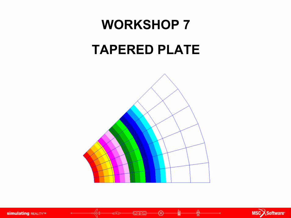
WORKSHOP 7
TAPERED PLATE
WS7-2NAS120, Workshop 7, May 2006Copyright© 2005 MSC.Software Corporation
WS7-3NAS120, Workshop 7, May 2006Copyright© 2005 MSC.Software Corporation
Workshop Objectives:1. Learn to use fields to define element thickness
2. Learn to use fields to create variable pressure loading
WS7-4NAS120, Workshop 7, May 2006Copyright© 2005 MSC.Software Corporation
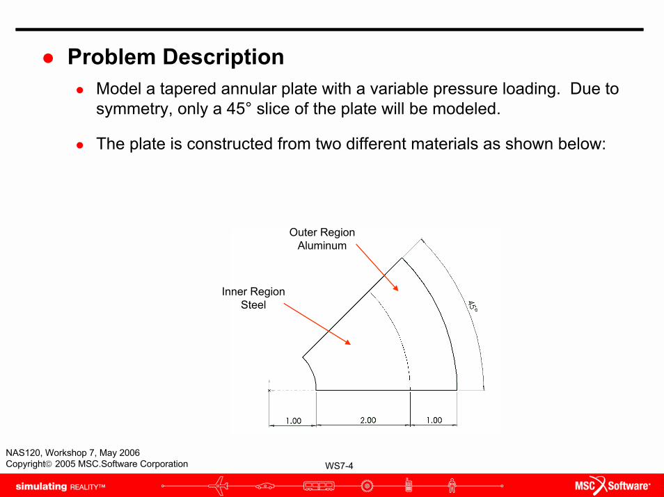
Problem DescriptionModel a tapered annular plate with a variable pressure loading. Due to symmetry, only a 45° slice of the plate will be modeled.
The plate is constructed from two different materials as shown below:
Inner RegionSteel
Outer Region Aluminum

WS7-5NAS120, Workshop 7, May 2006Copyright© 2005 MSC.Software Corporation
Problem Description (cont.)The thickness variation in the plate is shown below:
0
0.05
0.1
0.15
0.2
0.25
0 0.5 1 1.5 2 2.5 3 3.5 4 4.5
Radial Distance, r, inches
Thic
knes
s, in
ches
WS7-6NAS120, Workshop 7, May 2006Copyright© 2005 MSC.Software Corporation
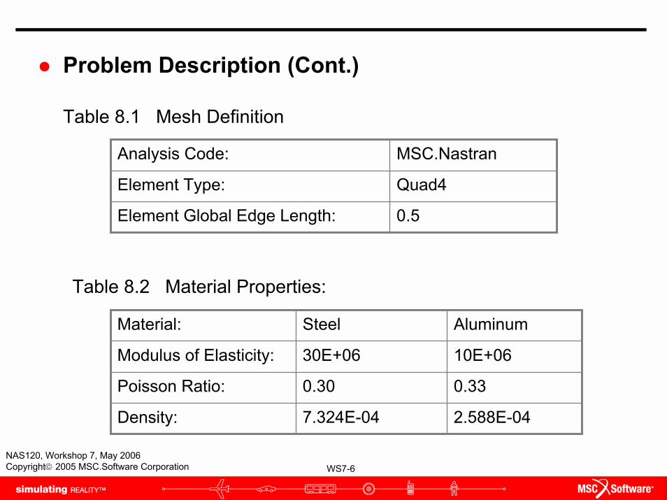
Analysis Code: MSC.Nastran
Element Type: Quad4
Element Global Edge Length: 0.5
Problem Description (Cont.)
Table 8.1 Mesh Definition
Table 8.2 Material Properties:
Material: Steel Aluminum
Modulus of Elasticity: 30E+06
0.30
7.324E-04
10E+06
Poisson Ratio: 0.33
Density: 2.588E-04
WS7-7NAS120, Workshop 7, May 2006Copyright© 2005 MSC.Software Corporation
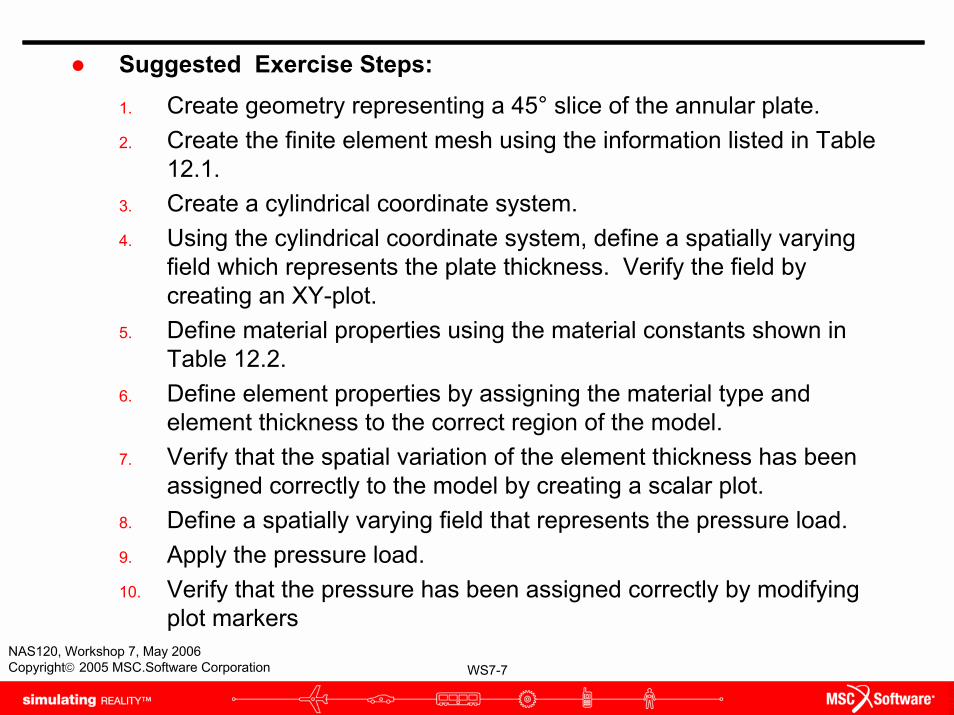
Suggested Exercise Steps:1. Create geometry representing a 45° slice of the annular plate.2. Create the finite element mesh using the information listed in Table
12.1.3. Create a cylindrical coordinate system.4. Using the cylindrical coordinate system, define a spatially varying
field which represents the plate thickness. Verify the field bycreating an XY-plot.
5. Define material properties using the material constants shown inTable 12.2.
6. Define element properties by assigning the material type and element thickness to the correct region of the model.
7. Verify that the spatial variation of the element thickness has been assigned correctly to the model by creating a scalar plot.
8. Define a spatially varying field that represents the pressure load.9. Apply the pressure load.10. Verify that the pressure has been assigned correctly by modifying
plot markers
WS7-8NAS120, Workshop 7, May 2006Copyright© 2005 MSC.Software Corporation
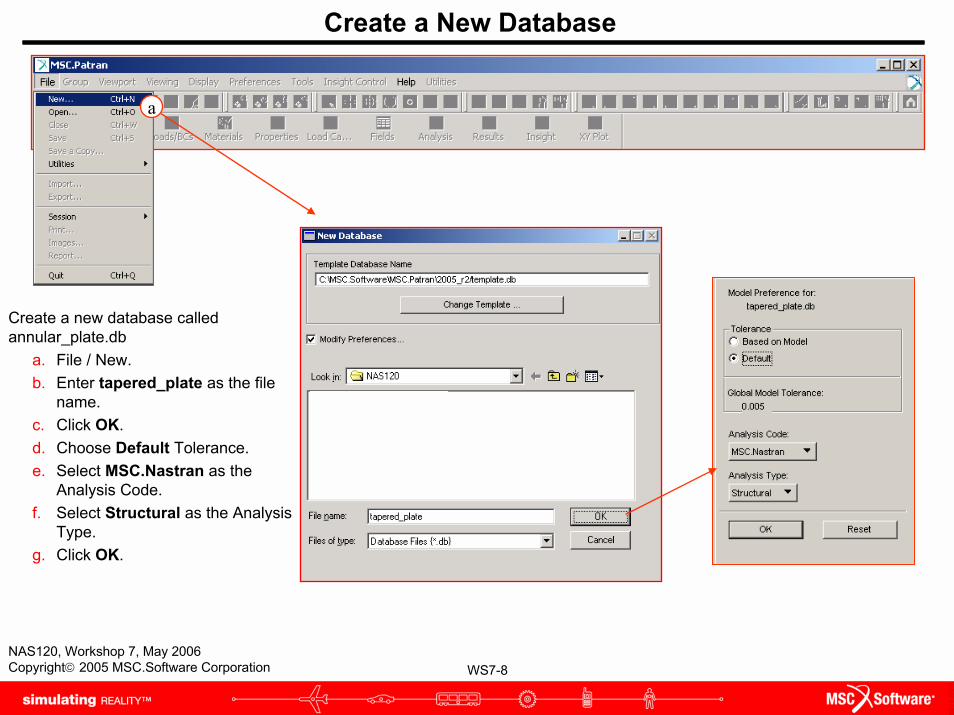
Create a New Database
Create a new database called annular_plate.db
a. File / New.b. Enter tapered_plate as the file
name.c. Click OK.d. Choose Default Tolerance.e. Select MSC.Nastran as the
Analysis Code.f. Select Structural as the Analysis
Type.g. Click OK.
a
WS7-9NAS120, Workshop 7, May 2006Copyright© 2005 MSC.Software Corporation
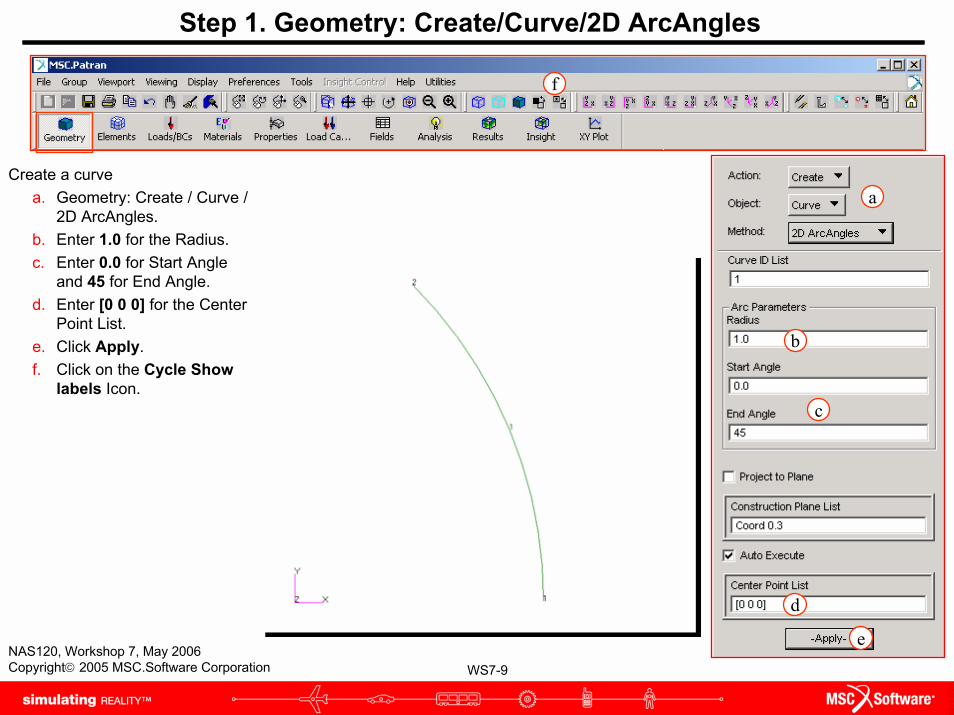
Create a curvea. Geometry: Create / Curve /
2D ArcAngles.b. Enter 1.0 for the Radius.c. Enter 0.0 for Start Angle
and 45 for End Angle.d. Enter [0 0 0] for the Center
Point List.e. Click Apply.f. Click on the Cycle Show
labels Icon.
Step 1. Geometry: Create/Curve/2D ArcAngles
a
b
c
d
e
f
WS7-10NAS120, Workshop 7, May 2006Copyright© 2005 MSC.Software Corporation
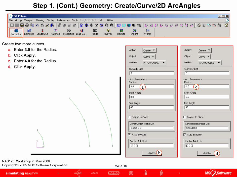
Create two more curves.a. Enter 3.0 for the Radius.b. Click Apply.c. Enter 4.0 for the Radius.d. Click Apply.
Step 1. (Cont.) Geometry: Create/Curve/2D ArcAngles
a c
db
WS7-11NAS120, Workshop 7, May 2006Copyright© 2005 MSC.Software Corporation
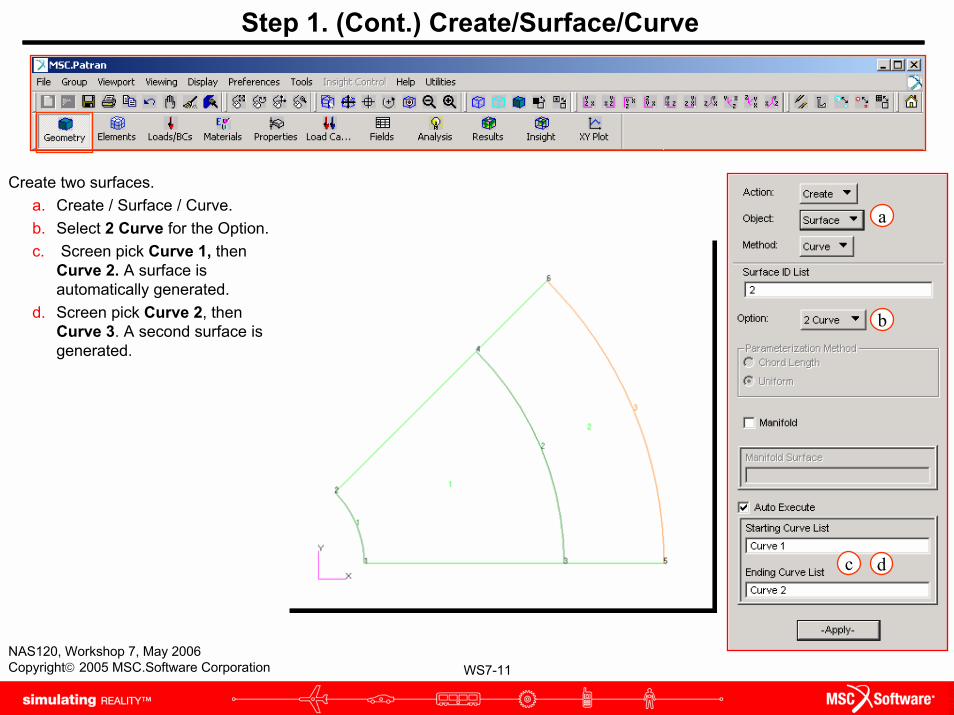
Create two surfaces.a. Create / Surface / Curve.b. Select 2 Curve for the Option.c. Screen pick Curve 1, then
Curve 2. A surface is automatically generated.
d. Screen pick Curve 2, then Curve 3. A second surface is generated.
Step 1. (Cont.) Create/Surface/Curve
a
b
c d

WS7-12NAS120, Workshop 7, May 2006Copyright© 2005 MSC.Software Corporation
Mesh the two surfaces.a. Elements: Create / Mesh /
Surface.b. Select IsoMesh as the
Mesher.c. Select Quad4 Element
Topology.d. Select both surfaces for
the Surface List.e. Enter 0.5 as the Global
Edge Length.f. Click Apply.g. Click on Cycle Show
labels icon.
Step 2. Finite Elements: Create/Mesh/Surface
a
bc
d
e
f
g
WS7-13NAS120, Workshop 7, May 2006Copyright© 2005 MSC.Software Corporation
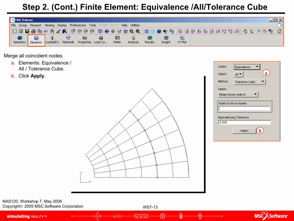
Step 2. (Cont.) Finite Element: Equivalence /All/Tolerance Cube
Merge all coincident nodes.a. Elements: Equivalence /
All / Tolerance Cube.b. Click Apply. a
b
WS7-14NAS120, Workshop 7, May 2006Copyright© 2005 MSC.Software Corporation
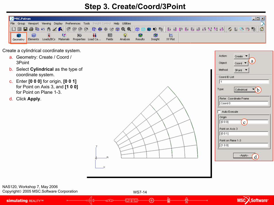
Create a cylindrical coordinate system.a. Geometry: Create / Coord /
3Pointb. Select Cylindrical as the type of
coordinate system.c. Enter [0 0 0] for origin, [0 0 1]
for Point on Axis 3, and [1 0 0]for Point on Plane 1-3.
d. Click Apply.
Step 3. Create/Coord/3Point
a
b
c
d
WS7-15NAS120, Workshop 7, May 2006Copyright© 2005 MSC.Software Corporation
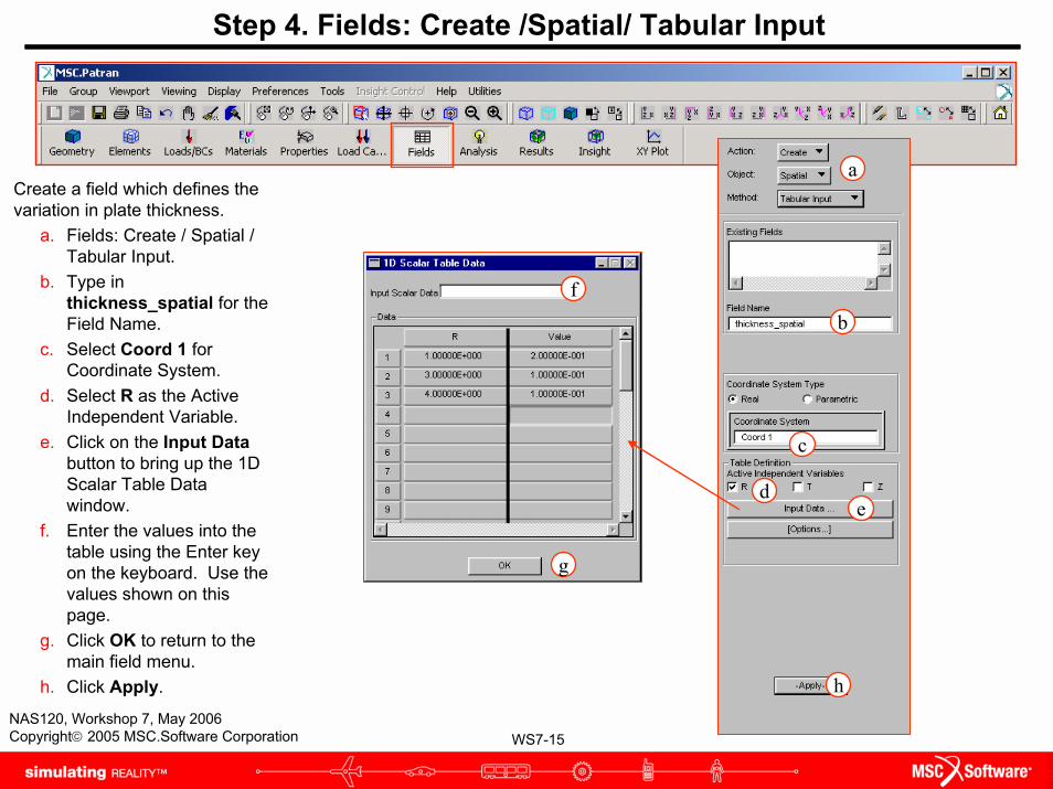
Step 4. Fields: Create /Spatial/ Tabular Input
Create a field which defines the variation in plate thickness.
a. Fields: Create / Spatial / Tabular Input.
b. Type in thickness_spatial for the Field Name.
c. Select Coord 1 for Coordinate System.
d. Select R as the Active Independent Variable.
e. Click on the Input Databutton to bring up the 1D Scalar Table Data window.
f. Enter the values into the table using the Enter key on the keyboard. Use the values shown on this page.
g. Click OK to return to the main field menu.
h. Click Apply.
f
g
a
b
c
de
h
WS7-16NAS120, Workshop 7, May 2006Copyright© 2005 MSC.Software Corporation
a
b
c
f
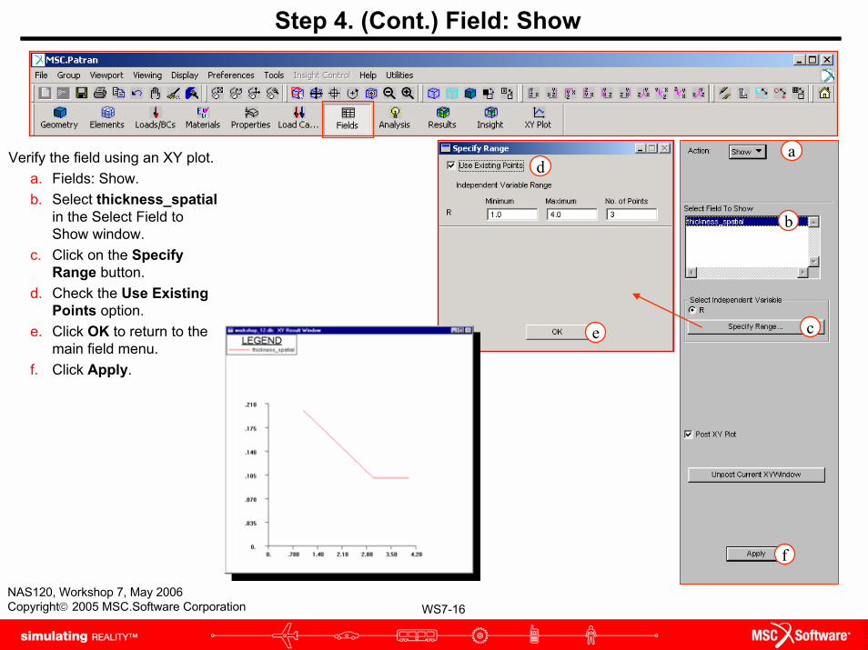
Step 4. (Cont.) Field: Show
Verify the field using an XY plot.a. Fields: Show.b. Select thickness_spatial
in the Select Field to Show window.
c. Click on the Specify Range button.
d. Check the Use Existing Points option.
e. Click OK to return to the main field menu.
f. Click Apply.
d
e
WS7-17NAS120, Workshop 7, May 2006Copyright© 2005 MSC.Software Corporation
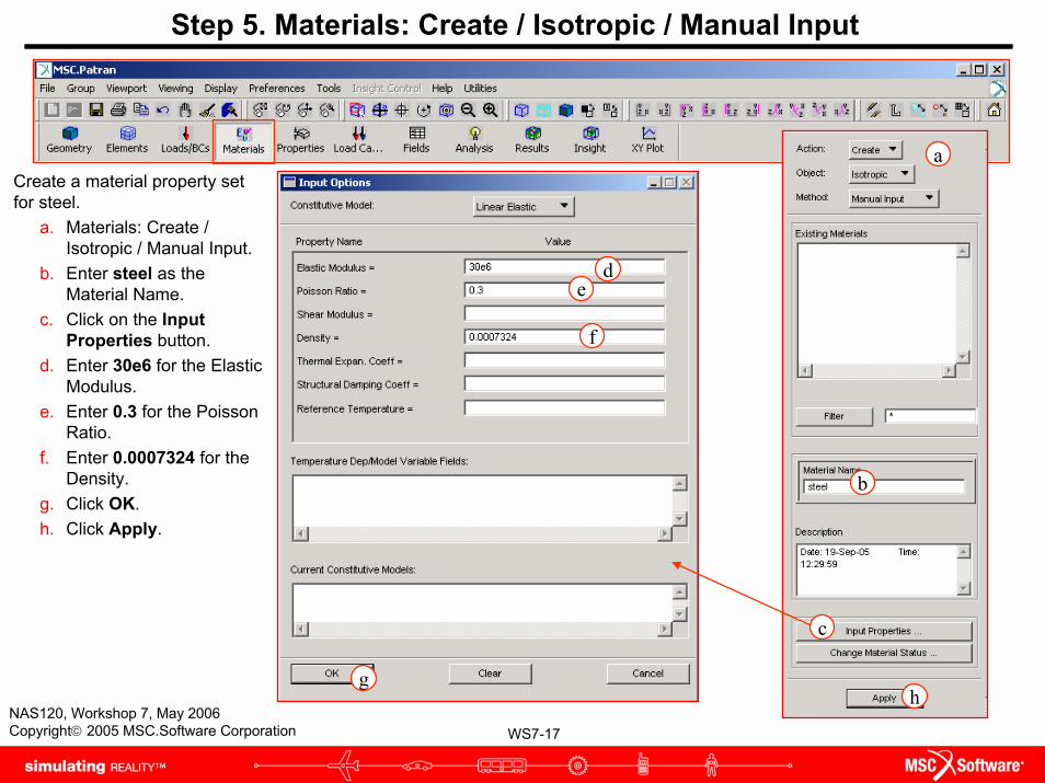
Step 5. Materials: Create / Isotropic / Manual Input
Create a material property set for steel.
a. Materials: Create / Isotropic / Manual Input.
b. Enter steel as the Material Name.
c. Click on the Input Properties button.
d. Enter 30e6 for the Elastic Modulus.
e. Enter 0.3 for the Poisson Ratio.
f. Enter 0.0007324 for the Density.
g. Click OK.h. Click Apply.
a
b
de
gh
f
c

WS7-18NAS120, Workshop 7, May 2006Copyright© 2005 MSC.Software Corporation
Step 5. (Cont.) Materials: Create / Isotropic / Manual Input
Create a material property set for aluminum.
a. Materials: Create / Isotropic / Manual Input.
b. Enter alum as the Material Name.
c. Click on the Input Properties button.
d. Enter 10e6 for the Elastic Modulus.
e. Enter 0.33 for the Poisson Ration.
f. Enter 0.0002588 for the Density.
g. Click OK.h. Click Apply.
a
b
de
g
h
f
c

WS7-19NAS120, Workshop 7, May 2006Copyright© 2005 MSC.Software Corporation
Step 6. Element Properties: Create / 2D / Shell
Define Element Properties for the inner portion of the plate.
a. Properties: Create / 2D / Shell.b. Enter prop_1 as the Property Set
Name.c. Click on the Input Properties
button.d. Click on the Select Material Icon.e. Click on the steel in the Select
Material window.f. Change the thickness option from
Real Scalar to Element Nodal.g. Click on the Select Field Icon.h. For the Thickness, select
thickness_spatial from the Field Definitions section.
i. Click OK.j. Select the inner surface for the
Application Region.k. Click Add.l. Click Apply.
d
g
i
f
e h
a
b
jk
l
c
WS7-20NAS120, Workshop 7, May 2006Copyright© 2005 MSC.Software Corporation
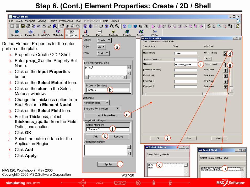
Step 6. (Cont.) Element Properties: Create / 2D / Shell
d
g
i
f
eh
Define Element Properties for the outer portion of the plate.
a. Properties: Create / 2D / Shell.b. Enter prop_2 as the Property Set
Name.c. Click on the Input Properties
button.d. Click on the Select Material Icon.e. Click on the alum in the Select
Material window.f. Change the thickness option from
Real Scalar to Element Nodal.g. Click on the Select Field Icon.h. For the Thickness, select
thickness_spatial from the Field Definitions section.
i. Click OK.j. Select the outer surface for the
Application Region.k. Click Add.l. Click Apply.
a
b
jk
l
c
WS7-21NAS120, Workshop 7, May 2006Copyright© 2005 MSC.Software Corporation
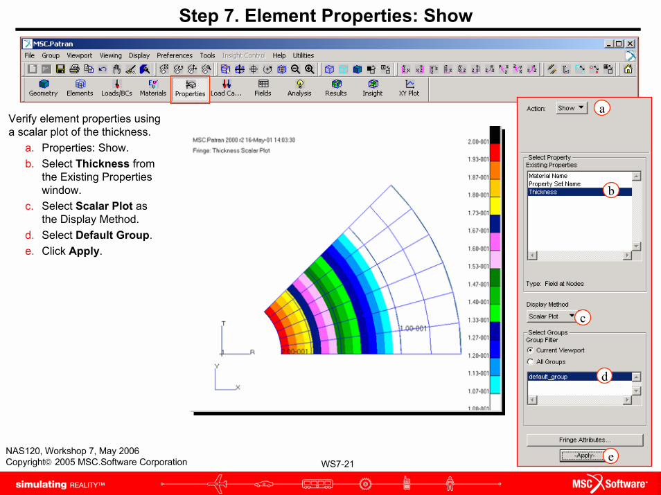
Step 7. Element Properties: Show
Verify element properties using a scalar plot of the thickness.
a. Properties: Show.b. Select Thickness from
the Existing Properties window.
c. Select Scalar Plot as the Display Method.
d. Select Default Group.e. Click Apply.
a
b
c
d
e
WS7-22NAS120, Workshop 7, May 2006Copyright© 2005 MSC.Software Corporation
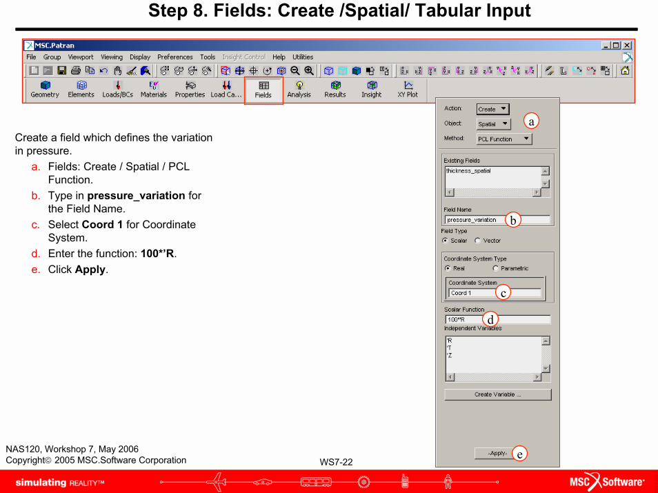
Step 8. Fields: Create /Spatial/ Tabular Input
Create a field which defines the variation in pressure.
a. Fields: Create / Spatial / PCL Function.
b. Type in pressure_variation for the Field Name.
c. Select Coord 1 for Coordinate System.
d. Enter the function: 100*’R.e. Click Apply.
a
b
c
d
e
WS7-23NAS120, Workshop 7, May 2006Copyright© 2005 MSC.Software Corporation
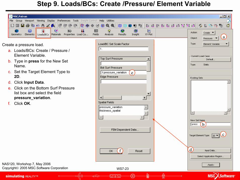
Step 9. Loads/BCs: Create /Pressure/ Element Variable
Create a pressure load.a. Loads/BCs: Create / Pressure /
Element Variable.b. Type in press for the New Set
Name.c. Set the Target Element Type to
2D.d. Click Input Data.e. Click on the Bottom Surf Pressure
list box and select the field pressure_variation.
f. Click OK.
e
f
a
b
c
d
WS7-24NAS120, Workshop 7, May 2006Copyright© 2005 MSC.Software Corporation
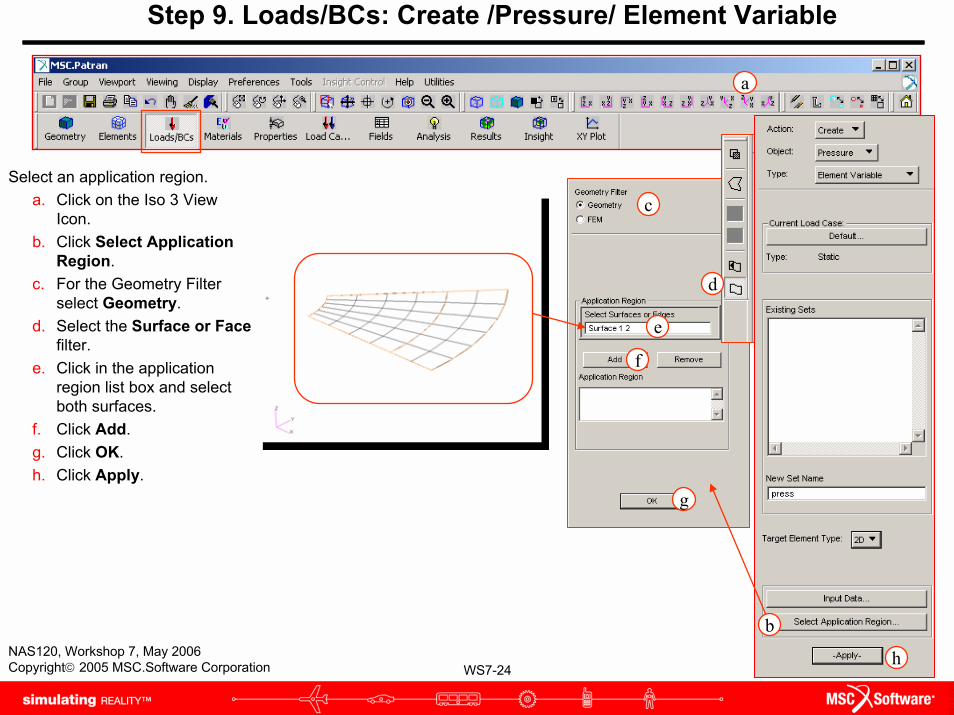
Step 9. Loads/BCs: Create /Pressure/ Element Variable
a
Select an application region.a. Click on the Iso 3 View
Icon.b. Click Select Application
Region.c. For the Geometry Filter
select Geometry.d. Select the Surface or Face
filter.e. Click in the application
region list box and select both surfaces.
f. Click Add.g. Click OK.h. Click Apply.
e
c
f
g
d
h
b

WS7-25NAS120, Workshop 7, May 2006Copyright© 2005 MSC.Software Corporation
Step 10. Modify Plot Markers
Modify the pressure plot markers.a. Display: Load/BC/Elem.Props.b. Select Show on FEM only.c. Click on Vectors/Filters.d. Change the length to Scaled-
Screen Relative.e. Click Apply.f. Click Cancel.g. Click on Label Style.h. Set the Label Format to
Integer.i. Click OK.j. Click Apply.
a
d
e f
h
i
j
b
cg

WS7-26NAS120, Workshop 7, May 2006Copyright© 2005 MSC.Software Corporation
Step 10. Modify Plot Markers
Re-plot the pressure plot markers.
a. Loads/BCs: Plot Markers.
b. Select the pressure load set.
c. Click Apply.
a
b
c

WS7-27NAS120, Workshop 7, May 2006Copyright© 2005 MSC.Software Corporation
ChallengeThis is the end of the workshop.
As time permits in this course, come back to this workshop to complete the analysis of this annular plate. The outer and inner edges of the plate are simply supported.
WS7-28NAS120, Workshop 7, May 2006Copyright© 2005 MSC.Software Corporation