Workshop 3 - Welcome to the UNC Department of Computer ... · Workshop 3 Sunday, March 13, ......
47
IEEE VR 2005 Workshop on Emerging Display Technologies March 13, 2005 Workshop 3 Sunday, March 13, 2005 Emerging Display Technologies—New Systems and Applications From Images to Sensing, Interaction and Enhancement Andreas Simon (Fraunhofer IMK) Greg Welch (University of North Carolina at Chapel Hill) Mark Bolas (University of Southern California and Fakespace Labs) The recent flurry of display technology development has produced families of technologies that make fixed and projected pixels cheaper, faster, more flexible, and of higher quality. These advances enable “smart pixels” and enable a number of burgeoning applications ranging from displays being used for better and more flexible images, to user interaction, scene sensing, and environment enhancement. Some example workshop submission topics include: • multiview, multifocal, or high dynamic range displays; • omnistereo projection systems; • ad hoc or “poor man’s” projection systems; • ultra wide field of view HMD optics; • ultra fast displays; • head-worn or hand-held (mobile) paradigms; • hybrid display systems and applications; • adaptive projector display systems; • extended color gamut or color matching displays; • projector-based user/device tracking, interaction, or Mixed Reality reconstruction; • embedded pixels for Spatially-Augmented Reality; and • rendering techniques associated with the above. This workshop should provide an opportunity to expand attendee thinking about ways to use contemporary display devices in VR systems and applications. i
-
Upload
nguyennhan -
Category
Documents
-
view
213 -
download
0
Transcript of Workshop 3 - Welcome to the UNC Department of Computer ... · Workshop 3 Sunday, March 13, ......
IEEE VR 2005 Workshop on Emerging Display Technologies March 13, 2005
Workshop 3
Sunday, March 13, 2005
Emerging Display Technologies—New Systems and ApplicationsFrom Images to Sensing, Interaction and Enhancement
Andreas Simon (Fraunhofer IMK)Greg Welch (University of North Carolina at Chapel Hill)
Mark Bolas (University of Southern California and Fakespace Labs)
The recent flurry of display technology development has produced families of technologies that make fixedand projected pixels cheaper, faster, more flexible, and of higher quality. These advances enable “smartpixels” and enable a number of burgeoning applications ranging from displays being used for better andmore flexible images, to user interaction, scene sensing, and environment enhancement. Some exampleworkshop submission topics include:
• multiview, multifocal, or high dynamic range displays;• omnistereo projection systems;• ad hoc or “poor man’s” projection systems;• ultra wide field of view HMD optics;• ultra fast displays;• head-worn or hand-held (mobile) paradigms;• hybrid display systems and applications;• adaptive projector display systems;• extended color gamut or color matching displays;• projector-based user/device tracking, interaction, or Mixed Reality reconstruction;• embedded pixels for Spatially-Augmented Reality; and• rendering techniques associated with the above.
This workshop should provide an opportunity to expand attendee thinking about ways to use contemporarydisplay devices in VR systems and applications.
i
IEEE VR 2005 Workshop on Emerging Display Technologies March 13, 2005
(This page intentionally left blank.)
ii
IEEE VR 2005 Workshop on Emerging Display Technologies March 13, 2005
Workshop Organizers
Andreas Simon is a Research Scientist at Fraunhofer IMK in Sankt Augustin, Germany and a Lecturer atthe University of Applied Sciences Aargau, Switzerland. His current research interests are the developmentand evaluation of rendering and interaction techniques for immersive virtual environments. Andreas Simongraduated with a M.S. in Computer Science from the Technical University in Berlin. He is a member of IEEEand of the German Gesellschaft fr Informatik. He has developed interaction devices and display systems likethe YoYo and the i-Cone. He can be reached at [email protected].
Greg Welch is a Research Associate Professor in the Computer Science Department at the University ofNorth Carolina at Chapel Hill. His research interests include Virtual/Augmented Environment trackingsystems and Telepresence. Welch graduated with highest distinction from Purdue University with a de-gree in Electrical Technology in 1986, and received a Ph.D. in Computer Science from UNC-Chapel Hill in1996. Prior to coming to UNC, Welch worked at NASAs Jet Propulsion Laboratory on the Voyager Project,and Northrop-Grumman’s Defense Systems Division on the AN/ALQ-135 electronic countermeasures sys-tem. Welch is a member of the IEEE Computer Society and ACM. He can be reached at [email protected].
Mark Bolas is a Visiting Associate Professor in the Interactive Media Department at the University ofSouthern California, and is Chairman of Fakespace Labs, Inc. His research focuses on creating technologiesand content for fluent interaction and perception of synthetic environments. Bolas graduated from theUniversity of California, San Diego with a B.A. in Physics and studies in Music and Signal Processing, andfrom Stanford University with an M.S. in Mechanical Engineering, Product Design. Bolas previously workedat Stanford University as a Consulting Assistant Professor and helped to found Polaris Road and SonicboxInc., as well as Fakespace Labs and Fakespace Systems. He can be reached at [email protected].
iii

IEEE VR 2005 Workshop on Emerging Display Technologies March 13, 2005
(This page intentionally left blank.)
iv
IEEE VR 2005 Workshop on Emerging Display Technologies March 13, 2005
Program and Table of Contents
Sunday, 13. March 2005
9:00–9:30 Welcome and Introduction
9:30–10:30 Session I
The DOME: A Portable Multi-Projector Visualization System for Digital Artifacts . . . . . . . . . . . . . . . . . . 3S. Webb, and C. Jaynes
A System for Rendering Panoramic Tele-immersion Images . . . . . . . . . . . . . . . . . . . . . . . . . . . . . . . . . . . . . . . . . . 7C. Kurashima, M. Cabral, and M. Zuffo
High Resolution Head Mounted Display . . . . . . . . . . . . . . . . . . . . . . . . . . . . . . . . . . . . . . . . . . . . . . . . . . . . . . . . . . . . 11I. Chapman
10:30–11:00 Coffee Break
11:00–12:30 Session II
Experiences with Multi-Viewer Stereo Displays Based on LCShutters and Polarization . . . . . . . . . . . . . . 15R. Blach, M. Bues, J. Hochstrate, J. Springer, and B. Frohlich
“Lumina Studio”: Supportive Information Display for Virtual Studio Environments. . . . . . . . . . . . . . . . .17A. Shirai, M. Takahashi, K. Kobayashi,H. Mitsumine, and S. Richir
A Scalable Holographic Display for Interactive Graphics Applications . . . . . . . . . . . . . . . . . . . . . . . . . . . . . . . 21T. Balogh, T. Forgacs, O. Balet, E. Bouvier, F. Bettio, E. Gobbetti, and G. Zanetti
Towards the Light Field Display . . . . . . . . . . . . . . . . . . . . . . . . . . . . . . . . . . . . . . . . . . . . . . . . . . . . . . . . . . . . . . . . . . . . 23R. Yang, S. Chen, X. Huang, S. Li, L. Wang, and C. Jaynes
12:30–14:00 Lunch
14:00–15:30 Session III
Monocular Depth Perception from Motion: A Study Proposal . . . . . . . . . . . . . . . . . . . . . . . . . . . . . . . . . . . . . . 27D. Reiners, and S. Pautz
A Window Manager for High Dynamic Range Display Systems . . . . . . . . . . . . . . . . . . . . . . . . . . . . . . . . . . . . . 31A. Pavlovych, A. Vorozcovs, and W. Stuerzlinger
Display, Sensing and Control Applications for Digital Micromirror Displays . . . . . . . . . . . . . . . . . . . . . . . . . 35I. McDowall, and M. Bolas
Leveraging Hollywood Set Design Techniques to Enhance Ad Hoc Immersive Display Systems . . . . . . 37J. Pair, A. Treskunov, and D. Piepol
15:30–16:00 Coffee Break
16:00–17:00 Open Panel Discussion
Rendering for Emerging Display Technologies. . . . . . . . . . . . . . . . . . . . . . . . . . . . . . . . . . . . . . . . . . . . . . . . . . . . . . .39T. Funkhouser, H. Kunz, D. Reiners, P. Slusallek, and R. Yang
17:00–17:15 Closing
v

IEEE VR 2005 Workshop on Emerging Display Technologies March 13, 2005
(This page intentionally left blank.)
vi
IEEE VR 2005 Workshop on Emerging Display Technologies March 13, 2005
9:30–10:30 Session I
The DOME: A Portable Multi-Projector Visualization System for Digital Artifacts. . . . . . . . . . . . . . . . . . . . . . .3S. Webb, and C. Jaynes
A System for Rendering Panoramic Tele-immersion Images . . . . . . . . . . . . . . . . . . . . . . . . . . . . . . . . . . . . . . . . . . . . . . 7C. Kurashima, M. Cabral, and M. Zuffo
High Resolution Head Mounted Display . . . . . . . . . . . . . . . . . . . . . . . . . . . . . . . . . . . . . . . . . . . . . . . . . . . . . . . . . . . . . . . . 11I. Chapman
1

IEEE VR 2005 Workshop on Emerging Display Technologies March 13, 2005
(This page intentionally left blank.)
2
The DOME: A Portable Multi-Projector Visualization System for DigitalArtifacts
Stephen Webb Christopher JaynesMersive Technologies University of Kentucky
1 Introduction
Multiprojector display is emerging as a viable approach toconstructing novel display systems. Because the pixels gen-erated by each projector are physically disjoint from theprojector/PC and other infrastructure, new display surfacegeometries can be explored. Of course, new technical barri-ers related to multi-projector tiling, geometric warping, andcooperative rendering must be addressed in the context ofthese displays.
The Office of the Future Project [13], the MetaverseProject [6], and others like it [5, 10, 2, 12, 3, 4] have beensuccessful in addressing many of the challenges. Uniquedisplay configurations ranging from immersive facilities [6,4] to multi-projector systems embedded in our everyday en-vironments [13, 11] and even mobile displays [8] are nowbeing developed.
Here we introduce a novel display system that wasspecifically developed to provide a robust, mobile, andmulti-user display for cooperative visualization tasks re-ferred to as the Digital Object Media Environment(DOME). In developing the DOME, a major focus of theproject is that of robust and automatic calibration on curveddisplay surfaces. We introduce a calibration technique thatutilizes a locally parametric model in conjunction with aglobal optimization phase that is combines the flexibility oftraditional non-parametric approaches with the robustnessof geometric transfer models implied by the multi-view ge-ometry at hand.
The DOME is composed of a vacuum-shaped back-projection screen that is illuminated by a cluster of pro-jectors mounted below the projection surface in a mobilecabinet. Each projector is connected to a personal com-puter that provides that projector with rendered images thatcontribute to the display. Computers are interconnected viaa standard gigabit Ethernet network. A pan-tilt camera ismounted within the DOME cabinet and is used to automat-ically compute the multi-projector calibration that providesfor seamless display of images for viewers outside of theDOME (Section 2).
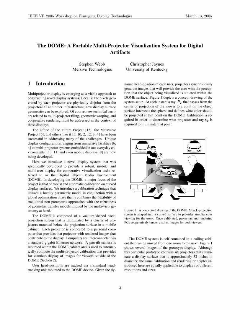
User head-positions are tracked via a standard head-tracking unit mounted to the DOME device. Given the dy-
namic head-position of each user, projectors synchronouslygenerate images that will provide the user with the percep-tion that the object being visualized is situated within theDOME surface. Figure 1 depicts a concept drawing of thesystem setup. At each instant a ray,
���, that passes from the
center of projection of the viewer to a point on the objectsurface intersects the sphere and defines what color shouldbe projected at that point on the DOME. Calibration is re-quired in order to determine what projector and ray,
���is
required to illuminate that point.
Figure 1: A conceptual drawing of the DOME. A back-projectionscreen is shaped into a curved surface to provides simultaneousviewing for the users. Once calibrated, projectors and renderingPCs cooperatively render distinct images for both viewers.
The DOME system is self-contained in a rolling cabi-ent that can be moved from one room to the next. Figure 1shows several images of the prototype display. Althoughthis particular prototype contains six projectors that illumi-nate a display surface that is approximately 32 inches indiameter, the same calibration and rendering principles in-troduced here are equally applicable to displays of differentresolutions and sizes.
IEEE VR 2005 Workshop on Emerging Display Technologies March 13, 2005
3

(a) (b) (c)
Figure 2: Three views of the DOME prototype display. (a) A view of the DOME from the side depicting the display surface shape,mounting cabinet, and projector/computer array. (b) A view of projectors and a camera is mounted beneath the display surface. Thecamera is attached to a pan-tilt unit to support calibration of the display across a wider field of view (circled in white for clarity).
1.1 Related Work
In similar work, Raskar et. al. [8] introduced an approachto geometric alignment for curved surface. The work is anextension of other methods that assume a planar surface andmodel geometric transfer via a homography [1] to non-flatsurfaces and the use of a quadric transfer. Calibration isthe process of discovering the unknown quadric transfer pa-rameters for a particular setup. Because the approach usesa global parametric model the method is robust to match-point localization error, but can result in image deforma-tions at points where the image display surface deviatesfrom a quadric surface.
Several researchers have directly calibrated projectordisplays on curved surfaces by explicitly building a lookup-table of projector to camera mappings (i.e. [14]). Althoughthe approach is appropriate for large display walls, the cali-brated result is defined in the reference frame of an observ-ing camera and novel views of three-dimensional immer-sive views of objects cannot be generated. Furthermore,the method does not easily extend to the multiple cameracase. In contrast to these methods, we introduce a com-bined calibration calibration approach that does not makeassumptions about the underlying screen surface while stillretaining the robustness that parametric models can afford.
2 Locally Parametric Calibration
Multi-projector calibration is the process of registering eachprojector pixel to a canonical surface which approximatesthe actual display surface. Local perturbations of thesemappings account for deviations from this canonical sur-face. These perturbations arise from screen surface abnor-malities, error in the estimation camera position, and differ-ences in the canonical model and true display shape. Thisapproach is motivated the observation that local errors (i.e
a discontinuity in the projected image where none exists onthe surface) are far more problematic that global, correlatederror.
In the case of the prototype DOME, a hemisphere is thecanonical model, but the true shape of the display surface isa hemisphere intersected with a cone.
The pan-tilt unit actuates to several overlapping viewpositions to capture � distinct images such that all pointson the display surface are seen in at least one image. Forthe results shown here, seven views were sufficient for theDOME display surface. For each camera position, all vis-ible projectors render a set of Gaussian fiducial s that arethen captured in the camera. Using binary encoding tech-niques, the observed fiducials are matched with projectedtargets to generate a set of corresponding matchpoints.
For a given pan-tilt position, � , the translation � ��� ����and rotation parameters of the camera are computed froman estimated initial position of the camera in the world ref-erence frame (a source of matchpoint deviations that will beaddressed). The camera intrinsics, � are recovered beforethe camera is place in the DOME and are then coupled witheach view position to derive a complete projection matrix:
����� ������������ �� ��� �!� �" ������� �# $&% ��('*)� " ��� �� � " �!� �" � " ��� �# $&% �" '*+� # ��� �� � # �!� �" � # ��� �# $&% �# '*,- - - .
/100243 � 5
(1)where �76 are the basis vectors of the estimated coordinate
system for the camera in the pan-tilt reference frame, � �6are the basis vectors for pan-tilt frame at position � and 'is the estimated offset from camera to pan-tilt. % 6 is the8:9<;
column of the upper left 3x3 rotation components ofthe transform matrix. Finally, = �5 is the coordinate systemchange from world (where the canonical surface is defined)to the the estimated frame of the pan-tilt unit.
IEEE VR 2005 Workshop on Emerging Display Technologies March 13, 2005
4
Because the canonical surface in the case of the DOMEis a hemisphere, the center of a matchpoint in the projectorframe, > � can related to a corresponding point in the camera,> � , via a degree- ? polynomial, > � �@�BA > ��C . This locallyparametric model can be used to eliminate invalid match-points and dramatically increase the robustness of the cali-bration phase. This is similar in spirit to methods that en-force particular geometric transfer functions globally suchas the planar homography and Quadric transfer. An im-portant distinction however, is that each local neighborhoodmay lead to a different model fit. This fit model is only usedto eliminate potentially noisy matchpoints and does not playa role in the global calibration.
The nine parameters of�
are recovered via robust leastsquares, for a given matchpoint over a 5x5 grid of neighbor-ing points. Note, that the matchpoint under consideration isnot used during the fit. Instead, the distance between thematchpoint and the fit model
�is measured and if this dis-
tance exceeds some threshold, the matchpoint is consideredto be in error, and is discarded. The model then used tointerpolate a new matchpoint at this location.
If we assume that observed points in the camera planearise from projected fiducials on the canonical surface, thenthe three-dimensional point, � �D�E�� � corresponding to im-age point
A 8GFIH C �is computed as the intersection the canoni-
cal surface with the back-projected ray defined by the pointand focal length J ,
�LK �� � -�-M-L. � �ENPO �QK �� � 8RH J . � � .This set of three-dimensional points observed in different
camera views must registered to a single three-dimensionalpoint cloud. If same projector point is seen in multipleviews only one is selected by iterating through cameraviews and adding only unique points until the point cloud isfully populated. Next, a 3D Deluanay triangulation is per-formed on this point cloud to compute neighbor relations.
Finally, this 3D mesh is modeled as a spring system inwhich each edge has a spring constant of one and a lengthcorresponding to a distance metric that related to the sep-aration of the two points on the sphere. In the case whentwo points arise from the same camera view, the distanceis equivalent to the geodesic distance. However, if the twopoints > �� and > "S are seen in to different camera views, thedistance between the two points T A > �� F > "S C , is computed asthe geodesic distance between the first point as seen in thesecond view, > �S , and the the second point as in that sameview, T A > �S F > "S C .
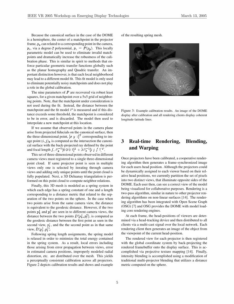
Following spring length assignments, the spring modelis relaxed in order to minimize the total energy containedin the spring system. As a result, local errors includingthose arising from error propagation between views, errorin estimated camera positions, improperly modeled radialdistortion, etc. are distributed over the mesh. This yieldsa perceptually consistent calibration across all projectors.Figure 2 depicts calibration results and shows and example
of the resulting spring mesh.
Figure 3: Example calibration results. An image of the DOMEdisplay after calibration and all rendering clients display coherentlongitude-latitude lines.
3 Real-time Rendering, Blending,and Warping
Once projectors have been calibrated, a cooperative render-ing algorithm then generates a frame-synchronized imagefor each users head position. Although the projectors couldbe dynamically assigned to each viewer based on their rel-ative head positions, we currently partition the set of pixelsinto two distinct views, that illuminate opposite sides of theDOME. Each user then, can see a correct view of the modelbeing visualized for collaborative purposes. Rendering is atwo-pass algorithm, similar in nature to other projector ren-dering algorithms on non-linear surfaces [14]. The render-ing algorithm has been integrated with Open Scene Graph(OSG) [7] and OSG provides the DOME with model load-ing core rendering engines.
At each frame, the head-positions of viewers are deter-mined via a head-tracking device and then distributed to allclients via a multi-cast signal over the local network. Eachrendering client then generates an image of the object fromthe viewpoint of the current head-position.
The rendered view for each projector is then registeredwith the global coordinate system by back-projecting therendered framebuffer onto the display surface. This is ac-complished via projective texture mapping [14]. Finally,intensity blending is accomplished using a modification oftraditional multi-projector blending that utilizes a distancemetric computed on the sphere.
IEEE VR 2005 Workshop on Emerging Display Technologies March 13, 2005
5
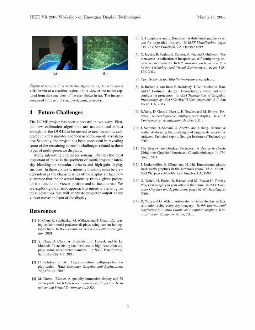
(a) (b)
Figure 4: Results of the rendering algorithm. (a) A user inspectsa 3D terrain of a coastline region. (b) A view of the model cap-tured from the same view of the user shown in (a). The image iscomposed of three of the six overlapping projectors.
4 Future ChallengesThe DOME project has been successful in two ways. First,the new calibration algorithms are accurate and robustenough for the DOME to be moved to new locations, cali-brated in a few minutes and then used for on-site visualiza-tion.Secondly, the project has been successful in revealingsome of the remaining scientific challenges related to thesetypes of multi-projector displays.
Many interesting challenges remain. Perhaps the mostimportant of these is the problem of multi-projector inten-sity blending on specular surfaces and high-gain displaysurfaces. In these contexts, intensity blending must be viewdependent as the characteristics of the display surface nowguarantee that the observed intensity from a given projec-tor is a function of viewer position and surface normal. Weare exploring a dynamic approach to intensity blending forthese situations that will attenuate projector output as theviewer moves in front of the display.
References[1] H. Chen, R. Sukthankar, G. Wallace, and T. Cham. Calibrat-
ing scalable multi-projector displays using camera homog-raphy trees. In IEEE Computer Vision and Pattern Recogni-tion, 2001.
[2] Y. Chen, D. Clark, A. Finkelstein, T. Housel, and K. Li.Methods for acheiving seamlessness on high-resolution dis-plays using uncalibrated cameras. In IEEE Visualization,Salt Lake City, UT, 2000.
[3] D. Schikore et. al. High-resolution multiprojector dis-play walls. IEEE Computer Graphics and Applications,20(4):38–44, 2000.
[4] M. Gross. Blue-c: A spatially immersive display and 3dvideo portal for telepresence. Immersive Projection Tech-nology and Virtual Environments, 2003.
[5] G. Humphreys and P. Hanrahan. A distributed graphics sys-tem for large tiled displays. In IEEE Visualization, pages215–223, San Francisco, CA, October 1999.
[6] C. Jaynes, B. Seales, K. Calvert, Z. Fei, and J. Griffieon. Themetaverse - a collection of inexpensive, self-configuring, im-mersive environments. In Intl. Workshop on Immersive Pro-jection Technology and Virtual Environments, pages 115–123, 2003.
[7] Open Scene Graph, http://www.openscenegraph.org.
[8] R. Raskar, J. van Baar, P. Beardsley, T. Willwacher, S. Rao,and C. Forlines. ilamps: Geometrically aware and self-configuring projectors. In ACM Transactions of Graphics,Proceedings of ACM SIGGRAPH 2003, pages 809–817, SanDiego, CA, 2003.
[9] R.Yang, D. Gotz, J. Hensly, H. Towles, and M. Brown. Pix-elflex: A reconfigurable, multiprojector display. In IEEEConference on Visualization, October 2001.
[10] J. Summet, R. Somani, G. Abowd, and J. Rehg. Interactivewalls: Addressing the challenges of large-scale interactivesurfaces. Technical report, Georgia Institute of Technology,2002.
[11] The Everywhere Displays Projector: A Device to CreateUbiquitous Graphical Interfaces. Claudio pinhanez. In Ubi-comp, 2001.
[12] J. Underkoffler, B. Ullmer, and H. Ishi. Emancipated pixels:Real-world graphics in the luminous room. In ACM SIG-GRAPH, pages 385–392, Los Angeles, CA, 1999.
[13] G. Welch, H. Fuchs, R. Raskar, and M. Brown H. Towles.Projected imagery in your office in the future. In IEEE Com-puter Graphics and Applications, pages 62–67, July/August2000.
[14] R. Yang and G. Welch. Automatic projector display surfaceestimation using every-day imagery. In 9th InternationalConference in Central Europe on Computer Graphics, Visu-alization and Computer Vision, 2001.
IEEE VR 2005 Workshop on Emerging Display Technologies March 13, 2005
6

A System for Rendering Panoramic Tele-immersion Images
Celso S. Kurashima, Márcio C. Cabral, and Marcelo K. Zuffo Laboratório de Sistemas Integráveis - University of São Paulo
{kurash, mcabral, mkzuffo}@lsi.usp.br
Abstract
This paper presents a novel technique for capturing
and rendering panoramic images with clusters of commodity PCs (Multi-camera Video Cluster and Graphics Cluster) with real-time capability. Aspects of camera positioning and calibration techniques are discussed. The reprojection method is proposed to solve the problem of rendering panoramic images to a CAVE Environment. 1. Introduction
Although panoramic image capturing and stitching are widely studied over the past years, projection techniques that give those images a real feeling of “immersiveness” are absent. The lack of these techniques underestimates the great potential of real-time panoramic image visualization. With the use of video clusters and graphics clusters [3], real-time processing for video capturing and rendering can be achieved.
2. System overview
The main goal of the system reported in this work is to render panoramic images that will be displayed onto the four walls of a four-sided CAVE - Cave Automatic Virtual Environment [1]. These walls are the faces of a structure shaped as a large cube. Images are back-projected to the semi-transparent screen that exists on the four vertical faces of the cube by high-resolution projectors. Then, a person that stands inside the cube can see 360-degree images and he or she is able to have the sensation of fully immersion in a new environment.
CAVE’s are commonly used to display synthetic images rendered by computer graphics techniques that create a virtual reality environment for the people
inside them. In this work, however, we will explore a CAVE to exhibit real-world panoramic images captured from remote places in real-time. Currently, this system is being implemented in our multi-projection immersive environment called CAVERNA Digital® [5]. We call this a Panoramic Tele-immersion System. Its block diagram is shown in Figure 1.
Figure 1. Block diagram of the panoramic tele-
immersion system. At the left of Figure 1, it is shown a set of N digital
video cameras connected to a cluster of PC computers, which we called multi-camera cluster. At the right side, it is shown another cluster of four PC computers, called graphics cluster. Each PC drives one of the four projectors that display images onto the screens of the CAVE walls. So, the multi-camera cluster is responsible for capturing multiple images and send then to the graphics cluster, which is responsible for rendering the panoramic images to be displayed in the CAVE.
The multi-camera cluster can be connected to the graphics cluster by a long-distance network, in case
IEEE VR 2005 Workshop on Emerging Display Technologies March 13, 2005
7
they are far apart. Also, they may share the same local network if both sides are close to each other.
In this system, the digital video cameras were used as a ring of cameras. This arrangement is described in the next section. Then, we propose the Reprojection method to render panoramic images for CAVE environments. This method is based on the image capture system of the ring of cameras. 3. The ring of cameras
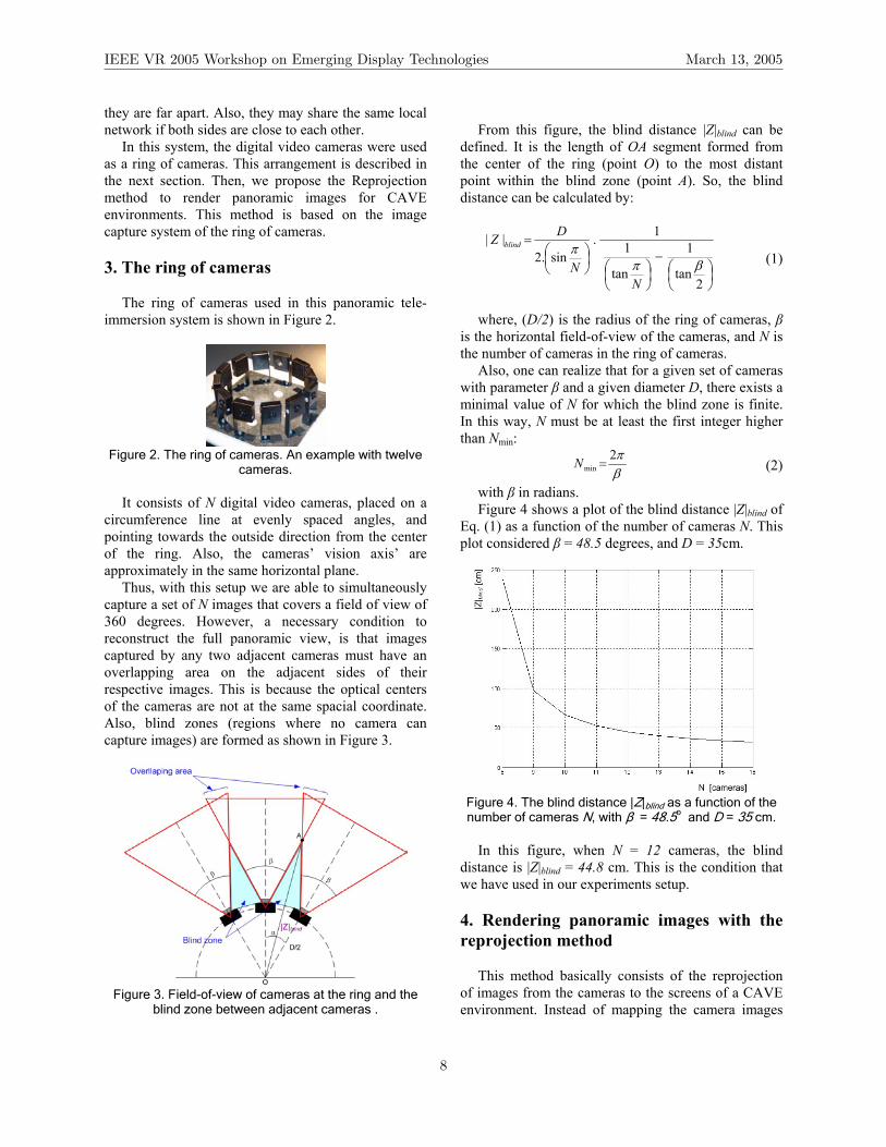
The ring of cameras used in this panoramic tele-immersion system is shown in Figure 2.
Figure 2. The ring of cameras. An example with twelve
cameras. It consists of N digital video cameras, placed on a
circumference line at evenly spaced angles, and pointing towards the outside direction from the center of the ring. Also, the cameras’ vision axis’ are approximately in the same horizontal plane.
Thus, with this setup we are able to simultaneously capture a set of N images that covers a field of view of 360 degrees. However, a necessary condition to reconstruct the full panoramic view, is that images captured by any two adjacent cameras must have an overlapping area on the adjacent sides of their respective images. This is because the optical centers of the cameras are not at the same spacial coordinate. Also, blind zones (regions where no camera can capture images) are formed as shown in Figure 3.
Figure 3. Field-of-view of cameras at the ring and the
blind zone between adjacent cameras .
From this figure, the blind distance |Z|blind can be
defined. It is the length of OA segment formed from the center of the ring (point O) to the most distant point within the blind zone (point A). So, the blind distance can be calculated by:
−
=
2tan
1
tan
11.
sin.2||
βππ
NN
DZ blind
(1)
where, (D/2) is the radius of the ring of cameras, β
is the horizontal field-of-view of the cameras, and N is the number of cameras in the ring of cameras.
Also, one can realize that for a given set of cameras with parameter β and a given diameter D, there exists a minimal value of N for which the blind zone is finite. In this way, N must be at least the first integer higher than Nmin:
βπ2
min =N (2)
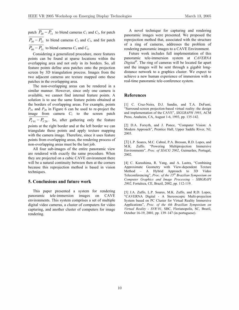
with β in radians. Figure 4 shows a plot of the blind distance |Z|blind of
Eq. (1) as a function of the number of cameras N. This plot considered β = 48.5 degrees, and D = 35cm.
Figure 4. The blind distance |Z|blind as a function of the number of cameras N, with β = 48.5o and D = 35 cm.
In this figure, when N = 12 cameras, the blind
distance is |Z|blind = 44.8 cm. This is the condition that we have used in our experiments setup. 4. Rendering panoramic images with the reprojection method
This method basically consists of the reprojection of images from the cameras to the screens of a CAVE environment. Instead of mapping the camera images
IEEE VR 2005 Workshop on Emerging Display Technologies March 13, 2005
8

on a cylinder surface, this method proposes to directly render the set of four images that will compose a full panoramic image for CAVE environments. This approach was derived from the concept of multiple images acquisition with the ring of cameras, and it is based on view-dependent texture mapping and image-based rendering techniques.
Figure 5 shows how the reprojection method works. The ring of cameras is actually located at a distant place from the physical location of the CAVE. So, remote images are being captured by the ring of cameras and are being sent to the computers that render images for the projection screen.
Figure 5. Reprojection of images from the ring of cameras to the projection screens of a CAVE.
The task of rendering a full panoramic image is
simplified by dividing it into four sub-images, i.e. one sub-image for each projection screen of the CAVE environment. The ring of cameras is virtually placed at the center of the cubic space of the CAVE, as shown in Figure 5. In this condition, the center of the ring of cameras O is coincident with point V, which will be referred as the viewpoint for the novel images. Therefore, a simplification can be achieved for we can use the same rendering algorithm to render the four novel sub-images (but just changing the input cameras) and projecting then independently onto the correspondent CAVE screens. In the following, we describe the reprojection method for rendering only one sub-image.
We have firstly considered a ring of twelve cameras for the sake of simplification, but this method can be easily generalized to any number of cameras. Only a sub-group of cameras are necessary to contribute with the formation of the screen image. As shown in Figure 5, the nearest set of five cameras is enough for this sub-image, because this screen does not receive the reprojection of other cameras.
Next, the sub-image to be rendered from viewpoint V can be considered as having two parts: the overlapping area and the non-overlapping area. In the example of Figure 5, there are four overlapping areas, where images of two adjacent cameras are overlapped on the projection screen. Also, there are three non-overlapping areas, where the image of only one camera can be used. The overlapping areas must be rendered before the non-overlapping areas because it takes in account the depth of objects of the scene. Figure 6 can be used to explain how a sub-image is rendered considering these two types of area.
Figure 6. The projection screen sub-image is composed by the overlapping areas and the non-overlapping areas. They depend on the scene objects’ depth. The depth of scene objects can be found by using
epipolar geometry methods from the theory of stereo vision [2]. In the implementation of this work we will apply the stereo feature tracking method that was previously used in [4].
In Figure 6, for generalization purposes an object of the scene is represented by a random line. We are particularly interested in determining the depth of the points at the borders between overlapping areas and non-overlapping areas. For example, the patch
0110 PP − belongs to the overlapping area delimited by cameras C0 and C1. Thus, when rendering the image for the projection screen, we can reproject the images of this patch captured by cameras C0 and C1 by blending them onto the projection screen located at patch 0110 VV PP − . The same operations are done for
IEEE VR 2005 Workshop on Emerging Display Technologies March 13, 2005
9
patch 1120 PP − to blend cameras C1 and C2, for patch
2130 PP − to blend cameras C2 and C3, and for patch
3140 PP − to blend cameras C3 and C4. Considering a generalized procedure, more features
points can be found at sparse locations within the overlapping area and not only in its borders. So, all feature points define area patches onto the projection screen by 3D triangulation process. Images from the two adjacent cameras are texture mapped onto these patches in the overlapping area.
The non-overlapping areas can be rendered in a similar manner. However, since only one camera is available, we cannot find internal feature points. A solution is to use the same feature points obtained at the borders of overlapping areas. For example, points P01 and P20 in Figure 6 can be used to re-project the image from camera C1 to the screen patch
2001 VV PP − . So, after gathering only the feature points at the right border and at the left border we can triangulate these points and apply texture mapping with the camera image. Therefore, since it uses feature points from overlapping areas, the rendering process of non-overlapping areas must be the last job.
All four sub-images of the entire panoramic view are rendered with exactly the same procedure. When they are projected on a cubic CAVE environment there will be a natural continuity between then at the corners because this reprojection method is based in vision techniques. 5. Conclusions and future work
This paper presented a system for rendering panoramic tele-immersion images on CAVE environments. This system comprises a set of multiple digital video cameras, a cluster of computers for video capturing, and another cluster of computers for image rendering.
A novel technique for capturing and rendering panoramic images were presented. We proposed the reprojection method that, associated with the structure of a ring of cameras, addresses the problem of rendering panoramic images to a CAVE Environment.
Future work includes full implementation of this panoramic tele-immersion system at CAVERNA Digital®. The ring of cameras will be located far apart and the images will be sent through a gigabit long-distance network to a graphics cluster. We expect to achieve a new human experience of immersion with a real-time panoramic tele-conference system. References [1] C. Cruz-Neira, D.J. Sandin, and T.A. DeFanti, “Surround-screen projection-based virtual reality: the design and implementation of the CAVE”, SIGGRAPH 1993, ACM Press, Anaheim, CA, August 1-6, 1993, pp. 135-142. [2] D.A. Forsyth, and J. Ponce, “Computer Vision: A Modern Approach”, Prentice Hall, Upper Saddle River, NJ, 2003. [3] L.P. Soares, M.C. Cabral, P.A. Bressan, R.D. Lopes, and M.K. Zuffo. “Powering Multiprojection Immersive Environments”, Proc. of SIACG 2002, Guimarães, Portugal, 2002. [4] C. Kurashima, R. Yang, and A. Lastra, “Combining Approximate Geometry with View-dependent Texture Method – A Hybrid Approach to 3D Video Teleconferencing”, Proc. of the 15th Brazilian Symposium on Computer Graphics and Image Processing – SIBGRAPI 2002, Fortaleza, CE, Brazil, 2002, pp. 112-119. [5] J.A. Zuffo, L.P. Soares, M.K. Zuffo, and R.D. Lopes, “CAVERNA Digital - A Stereoscopic Multi-projection System based on PC Cluster for Virtual Reality Immersive Applications”, Proc. of the 4th Brazilian Symposium on Virtual Reality - SVR’01, SBC, Florianopolis, SC, Brazil, October 16-19, 2001, pp. 139–147 (in portuguese).
IEEE VR 2005 Workshop on Emerging Display Technologies March 13, 2005
10

High Resolution Head Mounted Display
Iain Chapman Vobo Ltd, Cambridge, UK [email protected]
Abstract
We introduce a new format of head mounted display (HMD) in which images from large static monitors are guided to the headset through an articulated image guide. The system benefits from high resolution, wide field of view, and fast tracking. It offers six degrees of freedom, but is currently limited to applications with a small envelope requirement.
Concept testing has been successful and a full prototype will be completed soon.
1. Introduction
HMDs have been plagued by poor resolution, small field of view, and tracking lag. Projector systems can provide higher resolutions and larger fields of view, but also suffer from slow tracking and are physically large and relatively immobile and expensive. They are also prone to giving incorrect occlusion cues in certain applications.
We propose a new system in which a pair of high resolution images is transmitted from large static CRT monitors to a headset through an articulated image guide. The aim is to produce a head-worn display that allows an extensive degree of head movement and has high resolution and a wide field of view. The mechanical linkage will additionally permit very rapid tracking. A project was undertaken to test the feasibility of such a system. 2. Concept
An image-generating PC feeds two 22 inch CRT monitors. An optical pathway consisting of a series of mirrors and lenses guides the images produced by the monitors to the eyes of the user. The lenses and mirrors are fixed within an articulating frame designed in such a
way that the user can move with six degrees of freedom without altering the optical path (longitudinally).
Figure 1. Concept drawing
The articulating frame consists of a series of joints,
linked by rigid members. A joint consists of two mirrors, each mirror angled at 45 degrees to the principal ray, with a bearing allowing rotation of one mirror about the axis described by the principal ray between the two mirrors.
Movements of the user’s head cause the joints passively to rotate. The rotation of each joint causes an unwanted rotation of the image about the principal axis. In order to correct this, an optical encoder on each joint measures the degree of rotation, and the sum of all the rotations gives the total rotation of the image caused by all the joints. The correction is effected in real-time either optically with the use of an actively-controlled dove- or k-prism, or in software by rotating the images generated on the screens. The optical encoders additionally provide rapid head tracking.
IEEE VR 2005 Workshop on Emerging Display Technologies March 13, 2005
11

2.1 Weight and inertia
An equipoising system reduces the weight bearing on the user to zero, so the headset is effectively weightless with no forward or backwards lean. Since the image guide presents an upright real image in the headset in the same way that a head-mounted LCD or CRT would, the inertia due to helmet optics need not be higher than existing HMD systems. Indeed, since the correction of aberrations and distortion can be spread over the entire length of the optical path, intelligent design can reduce the weight and inertia of the optics at the headset end. The image guide imparts additional inertial load when the headset translates. 3. Test rigs
Two test rigs were constructed to examine the novel
aspects of the design. A physical test rig was used to examine the comfort and usability of various layouts of the articulated frame. An optical bench allowed the image quality for various optical configurations to be examined.
Figure 2. Early optical bench
3.1 Test results
Various permutations of six- and seven-joint layouts were constructed. Seven joints must be used in order to allow an unlimited range of head movement. A simpler six-joint layout gives 240º yaw and 120º in both roll and pitch and allows a shorter optical path. The additional inertia of the image guide was found to be perceptible above that of the headset optics only during large and unnaturally violent head translations. Passive equipoising (spring/counterweight) was ruled out in favour of an active system, which has not yet been built.
The optical system consists of input lenses, relays, and eyepieces. The left and right images are combined and split at either end of the image guide using polarizing beamsplitters. For this phase of the project only catalogue lenses were available. Visual assessment of the optical system indicated an extremely high quality of image over an extended field. Some field curvature was perceptible, but it was not beyond the ability of even a mature eye to accommodate. A circular image of diameter 1536 pixels with a 68º eyepiece gives a resolution of 2.7 arc minutes per pixel. In the six-joint layout outlined above, the user has a movement envelope of approximately two metres.
4. Future development
The two test rigs will shortly be combined into a
single full test rig. The active equipoise system will allow further reduction of the affects of inertia upon the user. Still higher resolution can be achieved by using more than two monitors at the input end of the image guide. Use of custom lenses will allow the field curvature to be reduced and the system envelope to be increased. 5. Conclusions
Early indications are that this system will provide a
HMD with extremely high resolution and fast tracking for activities that can be confined to a small (<3m) movement envelope.
6. Acknowledgements
Optical Physicist for the project is Brian Blandford, [email protected].
A patent application has been filed for the system. This work was partly funded by the UK Department
of Trade and Industry.
IEEE VR 2005 Workshop on Emerging Display Technologies March 13, 2005
12

IEEE VR 2005 Workshop on Emerging Display Technologies March 13, 2005
11:00–12:30 Session II
Experiences with Multi-Viewer Stereo Displays Based on LCShutters and Polarization . . . . . . . . . . . . . . . . . . 15R. Blach, M. Bues, J. Hochstrate, J. Springer, and B. Frohlich
“Lumina Studio”: Supportive Information Display for Virtual Studio Environments . . . . . . . . . . . . . . . . . . . . . 17A. Shirai, M. Takahashi, K. Kobayashi,H. Mitsumine, and S. Richir
A Scalable Holographic Display for Interactive Graphics Applications . . . . . . . . . . . . . . . . . . . . . . . . . . . . . . . . . . . 21T. Balogh, T. Forgacs, O. Balet, E. Bouvier, F. Bettio, E. Gobbetti, and G. Zanetti
Towards the Light Field Display . . . . . . . . . . . . . . . . . . . . . . . . . . . . . . . . . . . . . . . . . . . . . . . . . . . . . . . . . . . . . . . . . . . . . . . . 23R. Yang, S. Chen, X. Huang, S. Li, L. Wang, and C. Jaynes
13

IEEE VR 2005 Workshop on Emerging Display Technologies March 13, 2005
(This page intentionally left blank.)
14

Experiences with Multi-Viewer Stereo Displays Based on LC-
Shutters and Polarization
Roland Blach, Matthias Bues
CC Virtual Environments Fraunhofer IAO, Stuttgart, Germany
Jan Hochstrate, Jan Springer, Bernd Fröhlich Virtual Reality Systems Group
Bauhaus University Weimar Bernd.Frö[email protected]
1. Introduction Perspective projection in combination with head tracking is widely used in immersive virtual environments to support users with correct spatial perception of the virtual world. However, most projection based stereoscopic systems show a correct perspective view for a single tracked viewer only. Our intent is the development of a multi-viewer projection system for local collaboration in immersive environments. We focus on projection based systems where all users operate in the same interaction space. We present our implementation of a multi-view stereo system based on shuttered LCD-projectors and polarization. The combination of these separation techniques allows the presentation of more than one stereoscopic view on a single projection screen. We have successfully implemented shuttering of four projectors to support two users with individual perspectively correct stereoscopic views
Figure 1: System principle shown for three users. The polarization is used to separate the eyes. The shutters are used to separate the user. 2. Setup We use standard nematic liquid crystal (LC) or ferro-electric liquid crystal (FLC) shutter elements and LC-projectors to separate the individual users. Polarization is
used to separate the left and right eye view. Standard LC projectors emit already polarized light, which helps to set up such a system. However, the green channel is typically polarized orthogonal to the red and blue channel. We are using wave length selective half wave retarders to align the polarization of all three channels. For the left eye the polarization of the green channel is rotated by 90 degrees by the half wave plate, and for the right eye the red and blue channel are rotated by 90 degrees. Thus the polarization of all three color channels for the left and right eye are orthogonal to each other. Shutters consist of another half wave retarder embedded between two orthogonal polarization filters. Thus polarization is preserved and rotated by 90 degrees. Our setup is shown in Figure 2.
Figure 2: Filter principle for left and right eye. The projector is on the left and the users eye on the right. The shutters in front of the projectors and the users’ eyes are controlled by a custom built micro-controller circuit. The shutter clock is independent of the refresh rate of the LC projectors and we have achieved good results for three users by running between 50 and 80 Hz per user per eye. Each projector pair for a single user is driven by one PC with a dual head graphics card. The used software are
IEEE VR 2005 Workshop on Emerging Display Technologies March 13, 2005
15

the VR systems Avango [Tra99] and Lightning [Bla98]. Both are cluster aware and support an arbitrary amount of different views.
Figure 3: Hardware prototype: Customized glasses, filter adapter and projector stand. 3. Related Work Recently we have seen improvements in the field of shutter and projector technology, but there are still only a few attempts to provide multiple users with individual perspectively correct stereoscopic images. The two-user Responsive Workbench [Agr97] displays four different images in sequence on a CRT-projector at 144Hz, which results in 36Hz per eye per user. They also developed custom shutter glasses for cycling between four eyes. At these low frequencies, flicker is unavoidable and cross talk of CRT projectors is very apparent. Blom et al. [Blo02] extended this approach to support multi-screen environments such as the CAVE [Cru93], but still suffers from the same problems. Barco [Bar04] developed the “Virtual Surgery Table”, which provides two users with individual stereoscopic images by combining shuttered and polarized stereo into one system. Our work is an extension of this approach. Recently Bolas [Bol04] provides an overview of different multi-viewer setups. Preliminary Work of the authors has been described in [Fro05]. 4. Summary We have successfully implemented a working prototype for two users. We have not fully evaluated the setup but there are already some advantages and disadvantages visible:
• Combining polarization and shuttering doubles the brightness compared to a shutter only approach, since each user is exposed to an image for twice the time.
• Optimized optical filter combinations increase the brightness
• Circular polarization is simple to add
• Cross talk through the projector shutters and the shutter glasses
• Cross talk because of imperfection of the polarization elements
• Heat is developed on the projector shutter elements, if they are small and very close to the projector.
5. Future Work We are already in the process of extending the system to support four users. Besides the technical challenges, one of the most interesting research directions is the development of interaction paradigms for multiple users in these local environments. The general question remains: How scalable is the approach? What is the maximum number of users which can be supported? We are quite optimistic to be able to extend the system to up to four users. Beyond this limit, the main limitation is the remaining brightness per user and the crosstalk of the projector shutters. Here mechanical shutter approaches might be a solution. References [Agr97] Agrawala M. et al..: The Two-User Responsive Workbench: Support for Collaboration Through Individual Views of a Shared Space, Computer Graphics (SIGGRAPH '97 Proceedings), volume 31, pp. 327–332, 1997.
[Bar04] Barco: Virtual Surgery Table. http://www.barco.com/VirtualReality/en/products/
[Bla98] Blach R. et al, A Flexible Prototyping Tool for 3D Real-Time User-Interaction. Proceedings of the Eurographics Workshop on Virtual Environments 98 , 1998 pp. 195-203
[Blo02] Blom K., Lindahl G., Cruz-Neira C.: Multiple Active Viewers in Projection-Based Immersive Environments. Immersive Projection TechnologyWorkshop, March 2002
[Bol04] Bolas M, McDowall I, Corr D
New Research and Explorations into Multiuser Immersive Display Systems, IEEE Computer Graphics & Applications Jan/Feb 2004 pp18-21
[Cru93] Cruz-Neira, C., Sandin, D.J., and DeFanti, T.A. Surround-screen Projection-based Virtual Reality: The Design and Implementation of the CAVE. Proceedings of SIGGRAPH '93, 135-142, 1993.
[Fro05] Fröhlich B. et al., Implementing Multi-Viewer Stereo Displays. Proceedings of WSCG 2005 in Plzen, 2005
[Tra99] Tramberend, H. Avocado: A Distributed Virtual Reality Framework. Proceedings of VR’99 Conference, Houston, Texas, 14-21, March 1999.
IEEE VR 2005 Workshop on Emerging Display Technologies March 13, 2005
16
“Lumina Studio”: Supportive Information Display for Virtual Studio Environments
Akihiko Shirai CPNI Lab Laval [email protected]
Masafumi Takahashi JAIST
Kiichi Kobayashi NHK-ES, Inc.
Hideki Mitsumine NHK STRL [email protected]
Simon Richir CPNI Lab Angers
Abstract
This paper describes supportive information projecting techniques for virtual TV studio environments using back projected screen and real time video composition on graphics processing unit. In traditional TV, studios use blue or green back chroma-key for video composition and thus the actors cannot see the final composite without the preview monitor. Especially, when pointing a point on the background image, experiences or rehearsals are needed. In our system, the actors can see and point the supportive information displays such as computer generated background, virtual actors, reading scripts and/or final composites behind them. To compose the computer graphics to free area on the screen, we also develop a special real time video rendering program on GPU. It can be specified the keying chrominance and luminance by small profile data. In evaluation tests, we made a small weather forecasting TV program, and compared differences of suggestive and legacy method by the video and learning curves. 1. Introduction
Recently, computer graphics techniques have been improving extremely rapidly. We have a very clear picture of that in the cinema industries. In this special field, the public understanding of “photorealistic” is renewed every year. However, in current technologies, quality is not of the same level in cinema or real time TV programs. In comparison with cinema, TV production process has limitations in terms of production, costs and cycle of production. This is why we have to focus on special requirements for each of them. For example, photorealistic computer can render virtual actors with a few millions of polygons which can play incredible
actions with dynamic visual effects, but this type of character are not needed on a news TV program. Basically it should be broadcasted by actual human actors with detailed information. In this case, computer graphics power will be used for pixel filling or blending instead of polygon performance. We assume that realistic composing techniques will be needed in the next generation of TV environments like HDTV.
2. Related work “Chroma-key” is the most traditional method of video composition. It separates the background and the foregrounds like actors and other subjects using chrominance of images (Chroma) with blue or green colored background in a studio environment. It is the easiest method to compose background video and actual human and other subjects on real time or offline. Because this traditional method has some weak points, groups of NHK Science and Technical Research Laboratory have some related works to solve. 2.1. Synthesizing image in the studio
The first problem is due to the fact that the actors cannot see their final composed image on demand. Of course, they can see it on the preview monitor through out by real time keying hardware. But most of the time, actors have to face the camera or real/virtual subjects thus they cannot get the visual feedback on real time. For example, in weather forecasting program, the weathercaster has to point out the map on suitable timings. But it needs
IEEE VR 2005 Workshop on Emerging Display Technologies March 13, 2005
17

experiments, imagination or rehearsal. If the points are stable, small markers like blue stickers will help them but animated and/or interactive information are more difficult to point it synchronously. This problem is common for cinema production. Normally it is solved by actors’ sense and trials but if they can see virtual subjects on the wall or on the background, it is very helpful to play well. “Invisible Light Projection System”[1] is realized to show a subject image to be composed on the background screen using special liquid crystal shutter with front side projector. The shutter is rapidly controlled with camera frame synchronously, then actors can see the image but camera and audiences cannot see it. 2.2. Coaxial optics with infrared light source
The second problem is limits of lighting environment that is represented by “blue spilling”. Foreground subjects, especially actors skins are often influenced by the background color. For example, the actors’ face has some reflection areas like cheek or forehead. When these areas reflect background color, the system composes them as a background. This problem is mainly caused by lighting setups. It also depends on the situation of the actors but basically the lights should not be set on the side or behind the actors. Coaxial optics for camera and infrared (IR) light source has possibilities to solve this problem. “Axi-Vision Camera” [2] has two cameras and a coaxial optics for IR range and image-intensifier (I.I.) device with IR LED light sources. I.I. device can divide images like ultra rapid shutter on nano seconds order. When the IR LED illuminates the subjects with modulated intensity as triangle wave, the I.I. device can get its “increasing” and “decreasing” illuminated images in synchronously. The compared rate of both images contains depth information, then it can generate matte image that is not affected by light environments. These previous works have shown possibilities of new
composing methods but they use some special devices for their configuration.
3. Principle
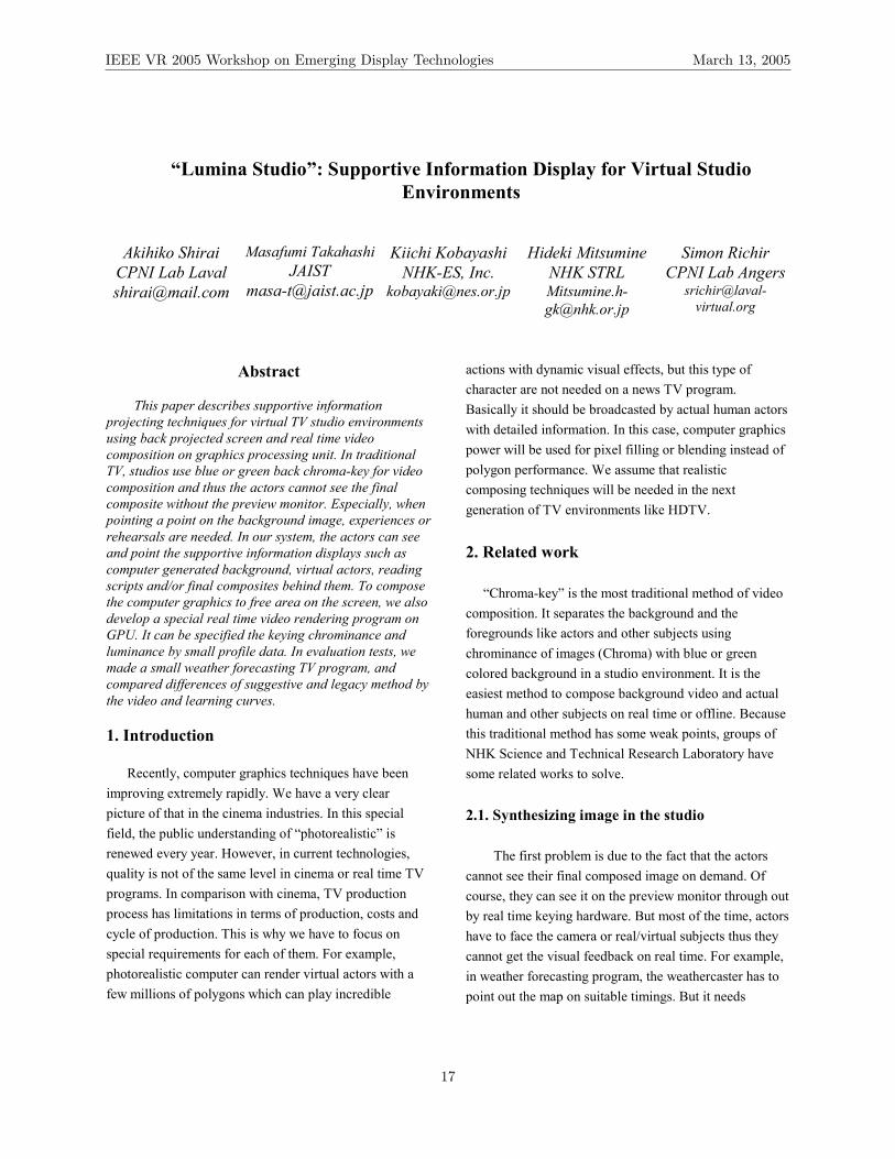
In this case, we assumed to set up a weather forecasting TV program with virtual studio on real time. In final composed video, the weathercaster should point a few locations on a map with correct description. 3.1. Supportive information display in the studio
Recently, some weather forecasting programs of NHK have had a large and ultra-bright display with touch sensors on the behind the weather caster. It is easier to collaborate with graphics, but small icons to make interactive with the maps are not needed by audiences. And the background image quality is lower than video composed.
Figure 1 is a concept of “Lumina Studio”, a new method of virtual TV studio. Walls of studio structure are colored by blue or green and it has a projector with blue or green touchable semi transparent screen. If the projected image is not shown for TV audience, it works as an invisible prompter in the set. It is useful to show telescripts (typed scripts for TV program), composing image, composed images, timer and/or director’s directions. Its quality of image is not important because of the area is overrode by composed image. 3.2. CAVE style display for virtual TV studio “CAVE”, the multi 3D display system was invented by UIC-EVL at 1991[3]. “CAVE style display” is configured by motion sensors for viewer person, stereoscopic displays as walls and a floor and liquid crystal shutter glass. This system designed as a display system then it is useful to experience immersive virtual environment in otherwise, these hardware are possible to make a new advanced virtual TV studio. Stereoscopic display represents two parallax images by shuttering of liquid crystal glasses if a left side of the glasses is set the front of TV camera, it can see the left side image only. If the system outputs blue screen to the left side and free
Virtual studio
CG sources
Final composite(real time)
SceneProjection
Virtual studio
CG sources
Final composite(real time)
SceneProjection
Figure 1: a concept of Lumina Studio
IEEE VR 2005 Workshop on Emerging Display Technologies March 13, 2005
18
images to the other side, the camera just take the blue screen image. It means the actors can see the free images with blue colored in the studio but the camera is not affected by the images. This is useful to make an integrated virtual TV studio environment between virtual set and real studio, CAVE style display has more abilities to improve it. The projector from the top is useful to tell correct standing point to the actors. And the motion sensors have a possibility to make a new camera system that can take the 6-DOF of camera with freehand. We already tried to generate composed image by CAVE style display, “SAS CUBE” then it works well (Figure 2). However if it will be used for broadcasting, the projectors should be brighter than lights in the TV studio. Mitsumine has already realized a projector based studio light environment. It can change the reflection color on the actor’s face from omni directional then it has possibilities to integrate with global illumination or image based rendering techniques with coaxial camera optics for infrared based matt technology (Figure 3). However, CAVE style display is little huge to develop it. And high speed liquid shutters or coaxial optics are not usual devices. Ideally it should not be a time divided frames because of video quality. 3.3. Real time GPU compositions
To realize the supportive screen in the studio, the system should be able to control the area of projected and backgrounds. The projected area from back side of screen has different light intensity from other area like actors or other backgrounds. Then luminance information (Lumina) on camera image has possibility to make a “Lumina key” but it also contains same intensity level of other area like illuminated face of the actors by lighting because of the projector is not brighter than studio light
environment. But chroma on the same image has different information from luminance. Then their combination keying has possibility to separate each area.
This composing is very difficult by existing video hardware. Chroma and Lumina levels are depend on studio setup then their tone should be corrected by curves. However it is possible if a small program on graphics processor unit (GPU) as known as pixel shader has a profile data for tone curve.
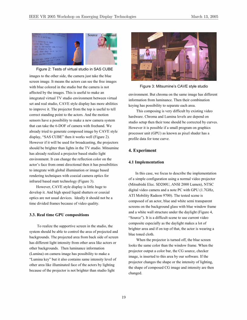
4. Experiment 4.1 Implementation In this case, we focus to describe the implementation of a simple configuration using a normal video projector (Mitsubishi Elec. SD200U, ANSI 2000 Lumen), NTSC digital video camera and a note PC with GPU (1.7GHz, ATI Mobility Radeon 9700). The tested scene is composed of an actor, blue and white semi transparent screens on the background glass with blue window frame and a white wall structure under the daylight (Figure 4, “Source”). It is a difficult scene to use current video composite especially as the daylight makes a lot of brighter area and if on top of that, the actor is wearing a blue toned cloth.
When the projector is turned off, the blue screen looks the same color than the window frame. When the projector output a color bar, the CG source, checker image, is inserted to this area by our software. If the projector changes the shape or the intensity of lighting, the shape of composed CG image and intensity are then changed.
Figure 3: Mitsumine’s CAVE style studio
ComposedSource ComposedSource
Figure 2: Tests of virtual studio in SAS CUBE
IEEE VR 2005 Workshop on Emerging Display Technologies March 13, 2005
19

The profile of tone collection for Lumina and Chroma key is given by one dimension texture file. Then changing the target Chroma and Lumina level does not need to modify the micro code of pixel shader. In this case, the target chroma is set as blue. Then the two blue bars on the color bar are shown as blue area (Figure 4, “Composed”).
If the system already has a Lumina and Chroma profile, the background is freely controllable, that means composed, invisible, or no affected. For example, if the projector outputs telescripts (typed scripts for TV program) with white color, it works like an invisible prompter on the wall. And black and blue areas are handled as background paper.
The shader program is not optimized but it runs over 300 FPS with MPEG1 encoded video source blending on 320x240 pixel resolution. 4.2 Evaluation To compare between proposed system and legacy method, we made an experimental program for the two groups. Both groups have a task that have to read a
weather forecasting text in English (second language) in just 30 seconds with correct motions for 10 trials. Group A used a text paper for 1-5 trial and used projector for 6-10 trial. Group B is reverse order. Figure 5 shows their time to finish. All subjects were closed to 30 seconds that means learning well. But Group B is faster than A.
5. Future works Lumina studio is a temporary work but invisible supportive information projection technique using GPU is applicative for other VR or computer vision techniques such as camera tracking, interactive or haptics. Acknowledgement This work was supported by the National Institute of Information and Communications Technology (NICT) of Japan. And we also thank ENSAM Paris (France). References [1] T. Fukaya, et al , “An effective interaction tool for performance in the Virtual Studio -Invisible Light Projection System-”, Institution of Electrical Engineers(IEE), IBC 2002, 2002, p.389-396 [2] M. Kawakita, K. Iizuka, T. Aida, H. Kikuchi, H. Fujikake, J. Yonai, and K. Takizawa, “Axi-vision camera (Real-Time Depth- Mapping Camera) ”, Applied Optics, Vol.39, pp.3931-3939, 2000. [3] C. Cruz-Neira, Sandin, D., DeFanti, T., Kenyon, R., Hart, J., “The CAVE: Audio Visual Experience Automatic Virtual Environment”,Communications of the ACM, vol. 35, no. 6 06/01/1992 - 06/01/1992, pp. 65-72
�������������� ������������������������� ������������������������� ������������������������� �����������
��
��
��
��
��
��
��
��
��
��
��
� � � � � � � ��
������������� ���� ��������������
�������������� �
��
���
���
������������������ ������������������������� ������������������������� ������������������������� �������
��
��
��
��
��
��
��
��
��
��
��
� � � � � � � ��
������������� ����������� �������
�������������� �
��
���
���
proposed proposed
Figure 5: Learning curves of proposed system
Capture IEEE1394/SDI
Tone profile
Color Space Conversion(Matrix multiplication)
Blend
Texture
Broadcasting
Foreground
Texture Locking
Matt
Background
3D Effects
Texture Unocking
RenderDVI-HDTV
Camera
Pixel Shader Compositions
CG source
Color CorrectionC C-1
luminance
chrominance
Tone curve correction
Rendering / Stream
Lumina key
Chroma key
Keying
Video sourceH/W Keying
Blend
���
�
�
���
�
�
−−−−=
083.0428.0511.0511.0339.0172.0114.0587.0299.0
C
���
�
�
���
�
�
−−=−
0732.1000.1698.0336.0000.1
371.10000.11C
RGB – YCbCr conversion matrixOne line RGB texture
LuminanceChromaMatt
CG SourceBlue structure
White screen Blue screen
Color bars Lumina key Chroma key
Source (daylight)
Composed (real time)
Matt
Blend
CG SourceBlue structure
White screen Blue screen
Color bars Lumina key Chroma key
Source (daylight)
Composed (real time)
Matt
Blend
Figure 4: Real time GPU compositions
IEEE VR 2005 Workshop on Emerging Display Technologies March 13, 2005
20
A Scalable Holographic Display for Interactive Graphics Applications
Tibor Balogh and Tamás ForgácsHolografika, Budapest, Hungary
{t.balogh|t.forgacs}@holografika.com
Olivier Balet and Eric BouvierCS Communication & Systèmes, Paris, France
{Olivier.Balet|Eric.Bouvier}@c-s.fr
Fabio Bettio, Enrico Gobbetti and Gianluigi ZanettiCRS4, Cagliari, Italy
{Fabio.Bettio|Enrico.Gobbetti|Gianluigi.Zanetti}@crs4.it
Abstract
We present a scalable holographic system design tar-geting multi-user interactive computer graphics applica-tions. The display device is based on back-projection tech-nology and uses a specially arranged array of microdis-plays and a holographic screen. The display is driven byDVI streams generated by multiple consumer level graph-ics boards and decoded in real-time by image processingunits that feed the optical modules at high refresh rates. AnOpenGL compliant library running on a client PC redefinesthe OpenGL behavior to multicast graphics commands toserver PCs, where they are re-interpreted in order to im-plement holographic rendering. The feasibility of the ap-proach is demonstrated with a working hardware and soft-ware 7.4M pixel prototype driven at 10-15Hz by two DVIstreams.
1 Short overview
We present a scalable holographic system design target-ing multi-user interactive computer graphics applications.
Display concept. Our display’s concept is different fromthe classic autostereoscopic or multi-view technology, lim-ited to showing different 2D images in different zones inspace. Such displays are often based on an optical mask ora lenticular lens arrays. A recent example is Matusik andPfister’s [2] large scale projection-based 3D display pro-totype consisting of 16 1024x768 projectors and lenticularscreens. A number of manufacturers (Philips, Sanyo, Sharp,Samsung, Stereographics, Zeiss) produce monitors basedon variations of this technology. Lenticular state of the artdisplays typically use 8-10 images, i.e., directions, at theexpense of resolution. A 3D stereo effect is obtained whenleft and right eyes see different but matching information.
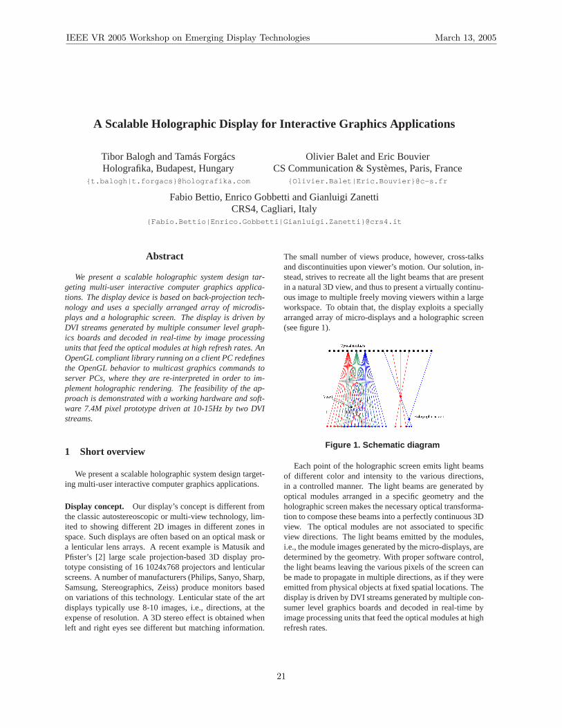
The small number of views produce, however, cross-talksand discontinuities upon viewer’s motion. Our solution, in-stead, strives to recreate all the light beams that are presentin a natural 3D view, and thus to present a virtually continu-ous image to multiple freely moving viewers within a largeworkspace. To obtain that, the display exploits a speciallyarranged array of micro-displays and a holographic screen(see figure 1).
Figure 1. Schematic diagram
Each point of the holographic screen emits light beamsof different color and intensity to the various directions,in a controlled manner. The light beams are generated byoptical modules arranged in a specific geometry and theholographic screen makes the necessary optical transforma-tion to compose these beams into a perfectly continuous 3Dview. The optical modules are not associated to specificview directions. The light beams emitted by the modules,i.e., the module images generated by the micro-displays, aredetermined by the geometry. With proper software control,the light beams leaving the various pixels of the screen canbe made to propagate in multiple directions, as if they wereemitted from physical objects at fixed spatial locations. Thedisplay is driven by DVI streams generated by multiple con-sumer level graphics boards and decoded in real-time byimage processing units that feed the optical modules at highrefresh rates.
IEEE VR 2005 Workshop on Emerging Display Technologies March 13, 2005
21
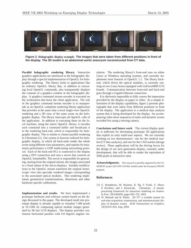
Figure 2. Holographic display example. The images that were taken from different positions in front ofthe display. The 3D model is an abdominal aortic aneurysm reconstructed from CT data.
Parallel holographic rendering library. Interactivegraphics applications are interfaced to the holographic dis-play through a special implementation of OpenGL for holo-graphic rendering. The library looks to applications likean ordinary OpenGL library that, in addition to execut-ing local OpenGL commands, also transparently displaysthe contents of a graphics window in the holographic dis-play. A graphics command stream encoder is executed onthe workstation that hosts the client application. The roleof the graphics command stream encoder is to masquer-ade as an OpenGL compliant rendering library applicationthat provides at the same time a local single-view OpenGLrendering and a 3D view of the same scene on the holo-graphic display. The library intercepts all OpenGL calls ofthe application. In addition to executing them on the lo-cal machine, using the native OpenGL library, it encodeseach command into a command buffer and broadcasts itto the rendering back-end, which is responsible for holo-graphic display. This is similar to cluster-parallel renderingin Chromium [1]. Our system is however tailored for holo-graphic display, in which all back-ends render the wholescene using different view parameters, and exploits for max-imum performance a UDP multicasting networking proto-col. Each of the back-end PCs is connected to the displayusing a DVI connection and runs a server that controls anOpenGL framebuffer. The server is responsible for generat-ing, starting from the original stream, the images associatedto a fixed subset of the micro-displays. Suitable modifica-tions to the OpenGL stream transform the original mono-scopic view into specially rendered images correspondingto the associated optical modules. This rendering imple-ments geometrical transformations, distortions and otherhardware specific calibrations.
Implementation and results. We have implemented aprototype hardware and software system based on the de-sign discussed in this paper. The developed small size pro-totype display is already capable to visualize 7.4M pixelsat 10-15Hz by composing optical module images gener-ated by 96 fast LCD displays. The display provides con-tinuous horizontal parallax with 0.8 degrees angular res-
olution. The rendering library’s front-end runs on eitherLinux or Windows operating systems, and currently im-plements most features of OpenGL 1.1. The library back-end, which drives the optical modules, is currently run-ning on two Linux boxes equipped with GeForce6800 GTSboards. Communication between front-end and back-endgoes through a Gigabit Ethernet connection.
It is obviously impossible to fully convey the impressionprovided by the display on paper or video. As a simple il-lustration of the display capabilities, figure 2 presents pho-tographs that were taken from different positions in frontof the display. The application is a medical data analysissystem that is being developed for the display. An accom-panying video show sequences of static and dynamic scenesrecorded live using a moving camera.
Conclusions and future work The current display qual-ity is sufficient for developing prototype 3D applicationsthat exploit its truly multi-user aspects. We are currentlyworking on two demonstrators: one for the medical mar-ket (CT data analysis), and one for the CAD market (designreview). These applications will be the driving forces forthe design of our next generation display, currently underdevelopment, that will be able to render the equivalent of50M pixels at interactive rates.
Acknowledgments. This research is partially supported by the CO-
HERENT project (EU-FP6-510166), funded under the EuropeanFP6/IST
program.
References
[1] G. Humphreys, M. Houston, R. Ng, F. Frank, S. Ahern,P. Kirchner, and J. Klosowski. Chromium: A stream-processing framework for interactive rendering on clusters.In Proc. SIGGRAPH, pages 693–702, 2002.
[2] W. Matusik and H. Pfister. 3D TV: a scalable system forreal-time acquisition, transmission, and autostereoscopic dis-play of dynamic scenes.ACM Transactions on Graphics,23(3):814–824, Aug. 2004.
IEEE VR 2005 Workshop on Emerging Display Technologies March 13, 2005
22

Towards the Light Field Display
Ruigang Yang, Shunnan Chen, Xinyu Huang, Sifang Li, Liang Wang, and Christopher JaynesUniversity of Kentucky, U.S.A.
Figure 1: A four-projector prototype of a light field display.
1 Introduction
True three-dimensional display, without the need for user-worn hardware, has the potential to revolutionize the tra-ditional human-computer visual interface. Perhaps this iswhy there has been a significant research effort related to theauto-stereoscopic display problem, first initiated by Suther-land [4] and remaining active today [2].
In the past several years there have seen significantresults emerging from this ongoing effort, in particular,lenticular screens have been used in conjunction with highresolution displays to provide several distinct views of ascene [3, 2]. In this paper we envision an autostereoscopicdisplay that is composed of an array of digital light projec-tors and a projection screen augmented with a sheet of mi-crolenses. Projectors are used to generate an array of pixelsat controlled intensity and color onto the projection screenand its array of microlenses. Each lenslet then transmits dif-ferent colored light rays into different directions in front ofthe screen. An early prototype display is shown in Figure 1.
Our proposed display in fact simulates an appropriatelight field for a given scene (physical objects emit or reflectlight in all directions–creating a light field), therefore it isnamed the light field display. It can simultaneously providemany viewers from different viewpoints stereoscopic effectwithout head-tracking or special gears.
To realize the light field display, two major obstaclesmust be overcome. First, there is the display calibrationissue, i.e., the correspondence between any projector pixeland the view ray emminating from a particular lenslet mustbe known. Secondly there is the real-time rendering issue.A stereoscopic display is only interesting if it can displaylive and interactive images.
2 Display Calibration
As illustrated in Figure 2, the problem of display calibrationis to register different components (projectors, screens, mi-crolens sheet etc.) in a single global coordinate frame. In or-der to achieve the autostereoscopic effect, the mapping be-tween the pixels in the frame buffer and viewing directionsin the three-dimensional viewing volume must be knownto great accuracy. Commercial lenticular displays rely onprecision manufacturing and are then restricted to limitedresolution and a fixed configuration. As an alternative, weuse computer vision techniques to discover the pixel-to-raymapping automatically.
ScreenImage Formation
Light Field Light FieldSampling
(+ distortion)Homography
ScreenCoordinates
Lens ArrayCoordinates
PixelCoordinates
FramebufferImage
Isometry Homography
Camera ImageCoordinates
Figure 2: Elements involved in display calibration and theassociated coordinate systems.
We are currently exploring a look-up based approach aswell as a full parametric approach. The first approach de-termines the mapping from frame-buffer pixel to ray bydirectly sampling the light-field produced by the display.Cameras at fixed known locations observe the screen whileprobe images are displayed. As a result, visibility maps forvarious viewpoints can be determined.
While this approach is very general and simple to imple-ment, it is does not scale to high resolution displays with avery large number of distinct views. In this case, we believethat a parametric approach, which precisely models the dis-play geometry and microlens optics, is necessary. The suc-cess of the parametric approach depends on the accuracyof the parametric model as well as the ability of the under-lying image processing steps used to measure parametersof the system. Recent results in match-point accuracy anduncertainty characterization are important here and our pre-liminary results are promising.
3 Real-time Multi-View Rendering
The imagery behind a 3D screen is a composite of manyimages of the scene rendered from different viewpoints,
IEEE VR 2005 Workshop on Emerging Display Technologies March 13, 2005
23

i.e., a Multiple-Center-of-Projection (MCOP) image. Us-ing a microlens array as the 3D screen, the correspond-ing pixels (a screenlet) behind each microlens form a tinyperspective view of the scene. We focus on efficient ren-dering of MCOP images from a geometric model (includ-ing polygonal meshes, higher-order surface primitives, andpoint-based models).
Commodity graphics hardware is designed to render animage from a single center of projection. A naive approachto render a MCOP image is to “viewport” each screenlet(Figure 3 middle). While this is fine for off-line process-ing, it is unlikely to achieve real-time performance. Herewe propose an algorithm that takes advantage of the regularlayout of the lenslets (pinholes). Since each pinhole (mi-crolenslet) is optically identical and placed in a regular pla-nar grid, there are many parallel rays. Rather than renderingeach perspective screenlet, we can render each group of par-allel rays using orthographic projection (Figure 3 right). Wecall this technique Parallel-Group Rendering (PGR). Com-pared with the most closely related multi-view renderingtechnique in [1], PGR is simple to implement, compatiblewith all existing acceleration techniques and hardware, andrequires no preprocessing.
Figure 3: Parallel rays in a microlens array. (Left) A teapot sceneis to be visualized. (Middle) A traditional way to render MCOPimages is to render the perspective view for each screenlet oneby one. (Right) Our novel rendering algorithm renders groupsof parallel rays, significantly reducing the number of renderingpasses needed.
4 Preliminary ResultsWe have built a light-field display prototype shown in Fig-ure 1. It consists of four XGA DLP projectors, each drivenby a PC. Note that most projectors have a minimum of im-age size of over 30 inches. In order to create a high densitydisplay over 100 DPI, we cover the projector lens with acommodity close-up lens. The prototype display density isa moderate 120 DPI with a display area of 16 × 12 inches.The screen is a diffuser layer with a spherical microlensarray. The diffuse layer is mounted on the focal plane ofthe microlens array. There are approximately 40 thousandlenslets illuminated by the projectors and the image behindeach lenslet contains about 10× 10 projector pixels.
Preliminary parametric calibration procedure results insubpixel projector registration accuracy (shown in Fig-ure 4), which is less than 0.1 mm on the screen. This isa promising result and ultimately will allow us to recoverthe entire projector-lightfield mapping.
Figure 4: We render a gridpattern to illustrate the regis-tration accuracy among projec-tors. The red (thick) linesshow the projector boundaries.This photo was taken behindthe screen (i.e., on the projec-tor side).
We have also experimented with the look-up based ap-proach. For example, by generating probe images consist-ing of a single pixel, a visibility map for two locations canbe recovered. The resulting visibility map is shown in Fig-ure 5(1). A stereo pair of a teapot is then merged into asingle image according to the visibility map (Figure 5(2))and sent to the display. An observer located at one of thecalibration spots then sees only the corresponding view ofthe teapot (Figure 5(3,4)).
Figure 5: Preliminary view-dependent effect. (1) A close-up im-age of the visibility map from calibration. Different colors encodewhich pixel is visible in which view(s). (2) We rendered a stereopair and merged them into a single image based on the visibilitymap. (3, 4) Right and left views of the composite image from twocalibrated viewpoints.
Regarding the PGR algorithm, we have observed over10 to 20 times speed-up for rendering images suitable fordisplay on our prototype. Currently each orthogonal viewmust be centrally composited into a final MCOP image foreach projector. We believe this simple operation can beoff-loaded to some simple customized hardware, which wehave begun to investigate.
References[1] Michael W. Halle. Multiple Viewpoint Rendering. In Proceedings of
SIGGRAPH 198, pages 243–254, 1998.[2] W. Matusik and H. Pfister. 3D TV: A Scalable System for Real-Time
Acquisition, Transmission, and Autostereoscopic Display of DynamicScenes. In Proceedings of SIGGRAPH 2004, pages 814–824, 2004.
[3] StereoGraphics Corporation. SynthaGram Monitor, 2003.http://www.stereographics.com.
[4] I. E. Sutherland. The ultimate display. In Proceedings of the Interna-tional Federation of Information Processing Congress, 1965.
IEEE VR 2005 Workshop on Emerging Display Technologies March 13, 2005
24
IEEE VR 2005 Workshop on Emerging Display Technologies March 13, 2005
14:00–15:30 Session III
Monocular Depth Perception from Motion: A Study Proposal . . . . . . . . . . . . . . . . . . . . . . . . . . . . . . . . . . . . . . . . . . 27D. Reiners, and S. Pautz
A Window Manager for High Dynamic Range Display Systems . . . . . . . . . . . . . . . . . . . . . . . . . . . . . . . . . . . . . . . . . 31A. Pavlovych, A. Vorozcovs, and W. Stuerzlinger
Display, Sensing and Control Applications for Digital Micromirror Displays . . . . . . . . . . . . . . . . . . . . . . . . . . . . . 35I. McDowall, and M. Bolas
Leveraging Hollywood Set Design Techniques to Enhance Ad Hoc Immersive Display Systems. . . . . . . . . . .37J. Pair, A. Treskunov, and D. Piepol
25

IEEE VR 2005 Workshop on Emerging Display Technologies March 13, 2005
(This page intentionally left blank.)
26
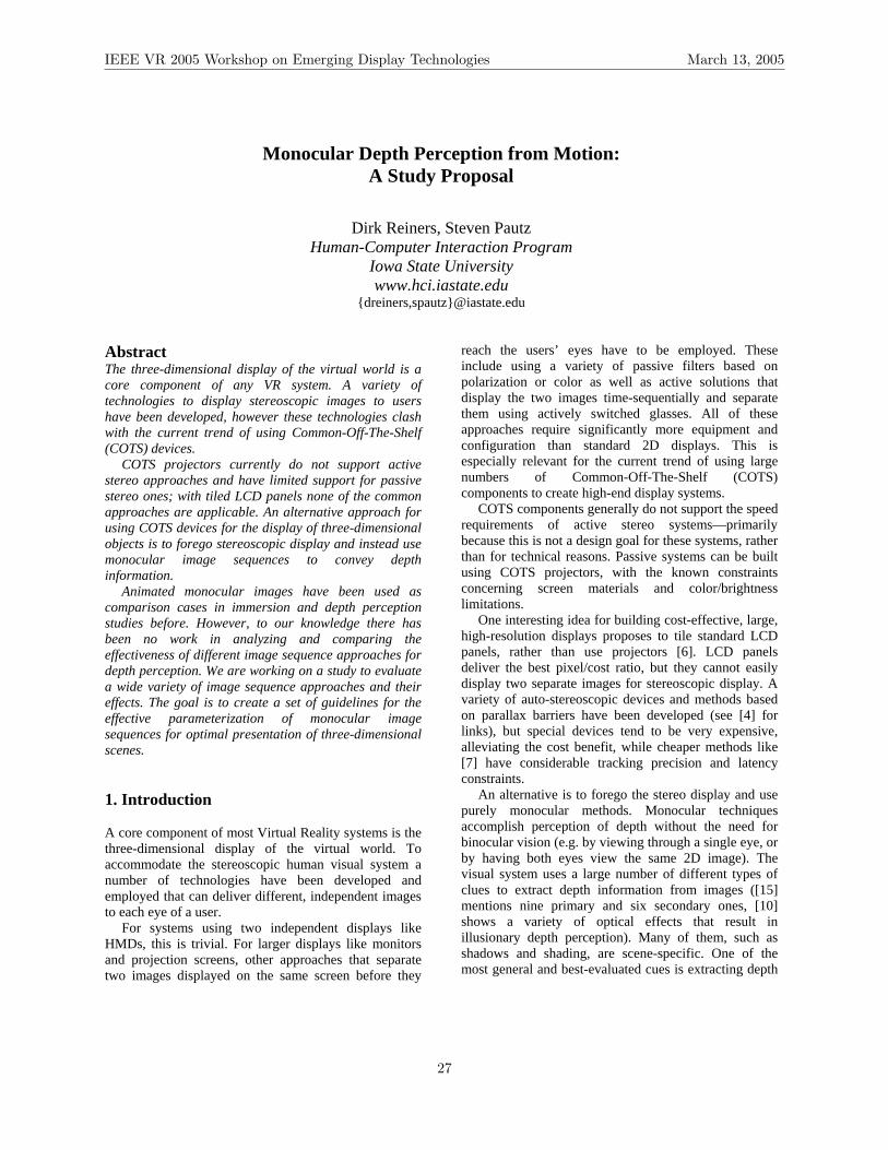
Monocular Depth Perception from Motion: A Study Proposal
Dirk Reiners, Steven Pautz Human-Computer Interaction Program
Iowa State University www.hci.iastate.edu
{dreiners,spautz}@iastate.edu Abstract The three-dimensional display of the virtual world is a core component of any VR system. A variety of technologies to display stereoscopic images to users have been developed, however these technologies clash with the current trend of using Common-Off-The-Shelf (COTS) devices.
COTS projectors currently do not support active stereo approaches and have limited support for passive stereo ones; with tiled LCD panels none of the common approaches are applicable. An alternative approach for using COTS devices for the display of three-dimensional objects is to forego stereoscopic display and instead use monocular image sequences to convey depth information.
Animated monocular images have been used as comparison cases in immersion and depth perception studies before. However, to our knowledge there has been no work in analyzing and comparing the effectiveness of different image sequence approaches for depth perception. We are working on a study to evaluate a wide variety of image sequence approaches and their effects. The goal is to create a set of guidelines for the effective parameterization of monocular image sequences for optimal presentation of three-dimensional scenes. 1. Introduction A core component of most Virtual Reality systems is the three-dimensional display of the virtual world. To accommodate the stereoscopic human visual system a number of technologies have been developed and employed that can deliver different, independent images to each eye of a user.
For systems using two independent displays like HMDs, this is trivial. For larger displays like monitors and projection screens, other approaches that separate two images displayed on the same screen before they
reach the users’ eyes have to be employed. These include using a variety of passive filters based on polarization or color as well as active solutions that display the two images time-sequentially and separate them using actively switched glasses. All of these approaches require significantly more equipment and configuration than standard 2D displays. This is especially relevant for the current trend of using large numbers of Common-Off-The-Shelf (COTS) components to create high-end display systems.
COTS components generally do not support the speed requirements of active stereo systems—primarily because this is not a design goal for these systems, rather than for technical reasons. Passive systems can be built using COTS projectors, with the known constraints concerning screen materials and color/brightness limitations.
One interesting idea for building cost-effective, large, high-resolution displays proposes to tile standard LCD panels, rather than use projectors [6]. LCD panels deliver the best pixel/cost ratio, but they cannot easily display two separate images for stereoscopic display. A variety of auto-stereoscopic devices and methods based on parallax barriers have been developed (see [4] for links), but special devices tend to be very expensive, alleviating the cost benefit, while cheaper methods like [7] have considerable tracking precision and latency constraints.
An alternative is to forego the stereo display and use purely monocular methods. Monocular techniques accomplish perception of depth without the need for binocular vision (e.g. by viewing through a single eye, or by having both eyes view the same 2D image). The visual system uses a large number of different types of clues to extract depth information from images ([15] mentions nine primary and six secondary ones, [10] shows a variety of optical effects that result in illusionary depth perception). Many of them, such as shadows and shading, are scene-specific. One of the most general and best-evaluated cues is extracting depth
IEEE VR 2005 Workshop on Emerging Display Technologies March 13, 2005
27
information from motion. However, there are still a large number of unexplored variations in using motion to convey depth. This is the topic of our study. 2. Previous Work A general overview of the cues used by the visual system is presented in [15]. They value motion as an important, but not all-encompassing, cue. It is trumped by occlusion and under some circumstances by other cues like size, but it is one of the stronger cues, more so for shape perception rather than scene layout. [16] predicts a high individual variability of the importance of different cues due to their redundancy.
Motion has been compared to stereo in its strength as a depth cue in a number of different tasks. [13] uses a path tracing task and comes to the conclusion that rotational motion itself is a stronger cue than stereo, but weaker than both combined. Similar results have been found for a node connection task in [14], which differentiates between user-controlled and pre-defined motion, but finds very little difference between them.
[17] notes that motion only makes sense in a perspective display environment: without perspective projection, motion is not useful as a depth cue. In their experiment, which included a large number of different cues, motion had little influence on position perception, but was an important factor for orientation and scaling tasks.
The findings in the literature are not totally conclusive, though. [19] shows motion in a mental rotation task, where user-controlled motion improves accuracy compared to uncontrolled motion, but both are slower and less precise than stereo. [20] uses a line-tracking task and finds that head-tracked motion is more accurate than stereo alone (but less than motion and stereo), but is slower than both of the alternatives. Finally, [18] uses user-controlled lateral motion in monocular absolute size/distance estimations and tasks and finds that it only weakly determines size and distance. 3. Monocular Depth Perception from Motion There are a wide variety of motion patterns that have been and can be used in studying depth perception. These patterns can be either user-controlled or forced to follow a predefined path. To avoid restricting the length of the user’s exposure to the forced motions, the predefined paths are generally cyclical. This is achieved either by the nature of the motion (e.g. 360-degree
rotation), by reversing the motion at the end of the path, or just by restarting the motion from the beginning.
[14] finds very little difference between user-controlled and forced motion, while [19] shows a noticeable benefit of user control. Given that we want to use web-based techniques to gather a large number of participants (see below), in our case only forced motion can be used, as it can be pre-calculated and stored as a sequence of images.
The motion types themselves can be split into three groups: rotational, sheared and translational.
Rotation is one of the most common methods. An object which rotates in space causes a perception of depth, generally related to the kinetic depth effect [11]. The animation is typically accomplished by moving the viewer in a full circle around the object, or by slowly rotating back and forth in a partial circle (also known as ‘rocking’). This method is intuitively used by users in a monoscopic interactive environment, and is also supported by the inertia effect of some virtual trackball implementations (notably Open Inventor’s). Due to its simplicity it has become a core feature of many visualization programs, for example the pyMol molecular visualization system [8] or MetaMorph for displaying confocal microscopy images [9].
Sheared motion is an intermediate between rotation and pure translation. It is derived from the perspective transformation generally used for stereo projection screens as suggested by Stereographics [21]. The idea is to keep the user and zero parallax settings fixed and only manipulate the eye distance. This allows a smooth interpolation between left and right eye positions while keeping an image without distortions orthogonal to the motion direction. A simple variant is applying a 90-degree rotation to create vertical motion.
Translation can be done in all three spatial directions, the most common one being horizontally, and is generally associated with observer motion. Both shearing and translation create depth through the parallax effect, which is based on the different speeds of object motion in the visual field relative to their distance to the viewer. A general explanation of this effect is based on consistency of clusters in the optical flow [11] across the visual field. Optic flow describes the retinal changes caused by the viewer’s movement within the scene, or by movement of an object composing the scene and is most often exemplified by transversal (in-out) motion. The influences of transversal and vertical motions on depth perception have been studied far less than horizontal motion.
All formal studies so far have tried to create the impression of smooth motion by using small steps between consecutive frames and high frame rates. This
IEEE VR 2005 Workshop on Emerging Display Technologies March 13, 2005
28

was mainly motivated by the expectation that lower frame rates and the corresponding large steps between frames increase the demands on the optical system and diminish the depth perception.
One of the more surprising observations (and the motivation for the initiation of this study) is that this is not really necessary. As few as two alternating images can be enough to create a strong depth perception (see [3] for examples). This is not a new observation: a dual image parallax-oriented process was actually marketed as VISIDEP™ by Jones et al [1]. In this method, images from a pair or set (generally “left and right”, or “top and bottom”) are presented sequentially. By alternating back and forth between the images at a certain frame rate (generally around 10 Hz), a viewer will perceive the scene with very noticeable depth. Many different variations of this method have been developed, known collectively by a variety of terms, including “parallax induction” [1], “alternating pairs” [2], “wobble stereo” and “time for space wiggle” [3] to name a few. Some interesting questions here are whether using two images is a special case that is processed by a different neural system than the other depth from motion effects (the stereo system is an obvious candidate), whether there is a continuum of effective frame counts and rates, and where the optimum depth perception occurs.
This observation opens new dimensions to the question of effective monocular depth perception from motion, namely the required or optimal frame rate and the number of frames in a cycle. There are already a number of other parameters that can be manipulated, namely viewer position and focal point and size of the interval spanned per cycle.
In a review of the literature on this topic, however, there seems to be little formal comparison of these techniques, or analysis of the relationship between the animation parameters and accuracy of the user’s depth perception. In order to obtain the best performance from COTS-based displays, a scientific examination of objective factors relating to the perception of depth resulting from these techniques is needed.
4. Research Plan Two general research questions relating to monocular depth perception from motion define the proposed study: which motion pattern is most effective, and what are the optimal parameters for that pattern? To address these questions, a software system has been developed to provide implementations of the animation methods described above. Seven different movement patterns are available: horizontal and vertical rotation, horizontal and vertical shearing, and horizontal, vertical and transversal
translation. We are able to manipulate the movement range, focal point, number of intermediary frames and animation speed for the animation, as well as scene features and viewer position. By testing and evaluating different animations and different settings, we hope to obtain data on the accuracy of, usability of, and ideal parameters for each animation method.
The test cases that will be used will focus on the motion aspects of depth perception and, as far as possible, eliminate other conflicting cues to generate meaningful results. The planned scenario is a relative distance scenario (is object A closer than object B?) using simple, similar symmetric objects (to reduce orientation bias concerning horizontal or vertical motion). Two concentric tori with the same minor and differing major radii are good candidates, but details are yet to be defined.
A problem of this approach is the relatively large number of independent variables and the resulting large number of necessary test cases to cover them. To approach this problem we are planning a two step process.
First, we will perform a pilot study on a relatively small number of users, using the system directly in house. The results of this study will be used to bracket the sensible parameter range, to reduce the total number of test cases to be run later. For example, if a particular animation method consistently fails at low frame rates, or requires a high number of interpolations to work properly, we can exclude the less-accurate or less-usable settings from future study. There is risk involved in this approach, but unless the web-based experiment gets slashdotted, there is no way to exhaustively cover all degrees of freedom otherwise.
Once the number of cases has been reduced to a manageable number, we will move the remaining cases online where a much greater number of people can be surveyed. We are creating a Flash-based website where visitors can view the different animations and contribute feedback on their accuracy and usability. This website is located at http://www.hci.iastate.edu/~dreiners/depth/ and will be used for gathering experimental results. Initial tests show that Flash is fast enough to display the animation loops at a very consistent frame rate on standard computers, allowing us to incorporate a large number of subjects without undue restrictions.
The online survey will allow users worldwide to view and submit accuracy and usability results. Given a suitable number of visitors, we should obtain statistically significant results on the effectiveness of the aforementioned monocular techniques.
IEEE VR 2005 Workshop on Emerging Display Technologies March 13, 2005
29

5. Expected Results Although at this point it is difficult to foresee the final results, from the initial tests we expect a bathtub curve in relation to the frame count, i.e. good accuracy for two and maybe a small number of frames, and also for a large number of frames (smooth motion), with a drop in the middle. The optimal frame rate on the low end is expected to be around the aforementioned 10 Hz, and on the high end the faster the better. It is not clear what the best motion pattern will be, but given that we will not have head tracking, intuition suggests that the shearing approach might have an advantage.
Nonetheless, the core expected result is to provide solid data on the optimal settings for each technique and an evaluation of their accuracy. This information can then be used to create monocular image sequences that convey depth with greater accuracy and comfort for the user, and that enable the use affordable systems composed of COTS components for interactive three-dimensional display. References [1] E.R. Jones, A.P. McLaurin, and L. Cathey, “VISIDEP™: Visual Image Depth Enhancement by Parallax Induction”, Proceedings, SPIE, Vol 457, Advances in Display Technology IV, Bellingham, WA, 1984, pp. 16-19. [2] E.R. Jones, A.P. McLaurin, “Three-Dimensional Imaging Through Alternating Pairs”, in McAllister, D.F., Stereo Computer Graphics and Other True 3D Technologies, Princeton University Press, Princeton, NJ, 1993, pp. 214-229. [3] J. Gasperini, “Stereo Images – Time for Space Wiggle”, at http://www.well.com/user/jimg/, August, 2003. [4] “3D Displays Links” at http://www.3dcgi.com/cooltech/displays/display-links.htm. [5] A.P. McLaurin, E.R. Jones, L. Cathey, “Advanced Alternating-Frame Technology (VISIDEP™) and Three-Dimensional Remote Sensing”, IEEE Transactions on Geoscience and Remote Sensing, Vol 26, No 4, July 1998, pp. 437-440. [6] J. Leigh, “GeoWall 2”, at http://www.evl.uic.edu/research/res_project.php3?indi=260 [7] D. Sandin, T. Margolis, G. Dawe, J. Leigh, T. DeFanti, “The Varrier Auto-Stereographic Display”, SPIE, vol 4297, no 25, San Jose, California, at http://www.evl.uic.edu/todd/ varrier/VarrierSPIE.html. [8] “PyMol”, at http://pymol.sf.net.
[9] “MetaMorph”, at http://www.image1.com/products.metamorph. [10] “Optical Illusions”, at http://www.michaelbach.de/ot [11] Braunstein, M.L., Depth Perception Through Motion, Academic Press, New York, 1976. [12] J.J. Koenderink, “Optic Flow”, Vision Research, 1986, pp. 161-180. [13] R.L. Sollenberger; P. Milgram, “Effects of stereoscopic and rotational displays in a three-dimensional path-tracing task”, Human Factors, Sept 1993 v35 n3 p483(17) [14] C. Ware; G. Franck, “Evaluating Stereo and Motion Cues for Visualizing Information Nets in Three Dimensions”, ACM Transactions on Graphics, Volume 15 , Issue 2 (April 1996), pp. 121-140 [15] J.E. Cutting, P.M. Vishton, “Perceiving layout and knowing distances: The integration, relative potency, and contextual use of different information about depth”, In W. Epstein, S. Rogers (eds) Handbook of perception and cognition, Vol. 5; Perception of space and motion, 1995, pp. 69-117, San Diego, CA; Academic Press [16] J.E. Cutting, “How the eye measures reality and virtual reality”, in Behavior Research Methods, Instruments and Computers, 1997, 29(1), pp. 27-36 [17] L.R. Wanger, J.A. Ferwerda, D.P. Greenberg; “Perceiving spatial relationships in computer-generated images” in IEEE Computer Graphics & Applications, Vol. 12, Issue 3 (May 1992), pp. 44-58 [18] A.C. Beall, J.M. Loomis, J.W. Philbeck, T.G. Fikes, “Absolute motion parallax weakly determines visual scale in real and virtual environments”, in SPIE Proceedings Vol. 2411 Human Vision, Visual Processing, and Digital Display IV, 1995 [19] G.S. Hubona, G.W. Shirah, D.G. Fout, “The effects of motion and stereopsis on three-dimensional visualization”, in Int. J. Human-Computer Studies, 1997, Vol. 47, pp. 609-627 [20] U. Naepflin, M. Menozzi, “Can movement parallax compensate lacking stereopsis in spatial explorative search tasks?”, in Displays, 2001, Vol. 22, pp 157-164 [21] “Stereographics Developer’s Handbook”, at http://www.stereographics.com/support/downloads_support/handbook.pdf
IEEE VR 2005 Workshop on Emerging Display Technologies March 13, 2005
30
A Window Manager for High Dynamic Range Display Systems
Andriy Pavlovych Andrejs Vorozcovs Wolfgang Stuerzlinger
York University, Toronto, Canada {andriyp, av, wolfgang}@cs.yorku.ca
Abstract The dynamic luminance range of many real-world
environments exceeds the capabilities of current display technology by several orders of magnitude. Recently, new display systems have demonstrated, which are capable of displaying images with a dynamic luminance range much more similar to that encountered in the real world.
The paper summarizes how the human eye perceives high dynamic luminance ranges, sources of high dynamic range data, how the new display systems work, as well as their limitations. The paper discusses the need for a high dynamic range window manager and presents an initial implementation. Finally, the results of a preliminary evaluation are presented.
1 Introduction
1.1 High Dynamic Range content in computer graphics
In the past few years, this issue of limited dynamic range of both imaging devices and displays has been extensively studied in the computer graphics community. In addition to being able to produce such imagery via methods such as physically based rendering [7], algorithms have been developed for capturing both still images [1, 5, 6, 8] and videos [3] of real environments with extended dynamic range.
As the dynamic range of luminance of such real and synthetic images often exceeds the capacity of current displays by orders of magnitude, new approaches to enable their presentation were also developed. One of the ways to display high dynamic range images is to transform the original range of intensities into a significantly smaller range of intensities a common desktop monitor can reproduce. Such process is called tone mapping and a number of tone mapping operators
have been developed to date. While these tone mapping operators (e.g. [2, 4, 10, 11] among others) allow for displaying high-dynamic-range (HDR) images in a recognizable and even aesthetically pleasing way, nobody would confuse a photograph rendered in this fashion with, say, watching the same scene through a window. The dynamic range of conventional displays is simply inadequate for creating a visual sensation of watching a real sunset or driving a car into oncoming traffic at night. To ease this problem, a new class of displays has recently been demonstrated [9], which allow for a contrast ratio of more than 50000:1, and have peak intensities in the range of 2700 cd/m2 to 8500 cd/m2, while lowering the black level to 0.05 cd/m2. For comparison, traditional displays usually reproduce a contrast of about 300:1 with a luminance range of approximately 1-300 cd/m2.
1.2 High Dynamic Range Display Technology
The principle underlying the devices in [9] is the use of a specialized high-intensity backlight for a transmission LCD panel. In one of the versions, a Digital Light Projector (DLP) was used for that purpose, in another – a grid of high-intensity white light emitting diodes, each of which can be controlled individually. Now, if the maximum contrast of the backlight image is c1:1, and the transmission ratio of the front LCD panel is c2:1, then the theoretical contrast ratio of the system is (c1·c2):1. The maximum luminance of such system will increase linearly with the maximum luminous power of the backlight. The reason that the resolution of the backlight image can be lower than the front panel is based on findings from the field of psychophysics, which show that very high contrast, although important on a global scale, cannot be perceived by humans at high spatial frequencies.
Displaying images on such a screen then requires the following technical steps:
IEEE VR 2005 Workshop on Emerging Display Technologies March 13, 2005
31
• Obtaining a linearly encoded high dynamic range image (radiance map).
• Generating the background image. • Generating the foreground image.
1.3 The Human Visual System
The human visual system is a remarkable apparatus, which allows us to perceive objects under a wide range of ambient illumination, from starlight to daylight, with a resolving power of up to 1'. However, it has several important limitations, which we need to be aware of in the context of displaying high-dynamic range content.
Adaptation Luminance The human visual system is useful over a wide range
of luminance values, and at any given time we can perceive no more than 5 orders of magnitude of dynamic range [4]. With the effect of time-adaptation, this range can be shifted up and down to cover 10 orders of magnitude.
Despite the wide visual field of view of the human eye, it is not possible to observe the whole scene simultaneously. Rather, we sequentially fixate our attention on local areas of the field of view, where the eye rapidly adapts to the average [9] brightness in the neighbourhood of 1–1.5° of visual angle centred at the fixation point. The adaptation luminance determines what part of the overall intensity range the eyes can be sensitive to at that given moment.
Dynamic Range and Local Contrast Sensitivity Furthermore, there is a limit to how much contrast
can be perceived in a very small neighbourhood of the visual field. That is, when the contrast between adjacent spots on the retina exceeds a particular threshold, we will no longer be able to perceive the relative magnitude of that contrast (roughly speaking, the spot on one side will appear white and the one on the other – black). If you separate the spots in space, you will again be able to see their variations in brightness. The threshold at which this occurs, the maximum perceived contrast, is reported to be around 150:1 [9].
Disability Glare Another major cause of human inability to
distinguish detail in areas of high contrast is the phenomenon of disability glare [12]. It is caused by light scattering inside the liquid medium of the eye, in the atmosphere, and sometimes the surface of the display. The effect of disability glare is to form a constant veiling luminance across a large part of the image area that obscures any detail that has a lower luminance value.
1.4 User Interface Issues
In traditional user interfaces, coupled with traditional displays, user interface elements can afford to have a constant brightness without the danger of becoming poorly distinguishable due to visual interference from the content that is being displayed. This is because the ability of traditional displays to reproduce contrast is not far from the 150:1 threshold. With HDR-capable displays, the dynamic range of the content displayed on the screen can have a substantial effect on the visibility of the user interface elements, and vice versa.
In this paper we demonstrate how the brightness of the non-HDR elements on the high dynamic range display can be compensated to reduce the negative effects of visual glare. We present several requirements that such an adjustment must fulfill and a preliminary implementation of the method on the projector-based version of the HDR display.
2 High Dynamic Range Window Manager
A simple way to combine a high dynamic range image with a low-dynamic range user interface would be to assign a constant average brightness to the LDR content, perhaps matching that of a standard office display (~150 cd/m2). However, for reasons discussed in the previous section, significant visibility problems can arise in cases where windows or interface elements (e.g. icons on a desktop or text in a word processor) are located close to the edge of a window that contains high dynamic range content.
It is non-trivial to decide what the brightness of the user interface should be. If the intensity of the user interface elements is significantly lower than the intensity of the adjacent portion of the HDR window, then these elements will be invisible due to effects of glare in human visual system. On the other hand, if their brightness is too high, they will themselves generate parasitic glare on the other areas of the screen, including the HDR content. Hence, we should limit the brightness of the user interface elements if we wish to make use of the lower end of the display’s luminance capability.
In summary, our goal is to maximize the visibility of user interface elements without adversely affecting the presentation of the HDR content.
IEEE VR 2005 Workshop on Emerging Display Technologies March 13, 2005
32
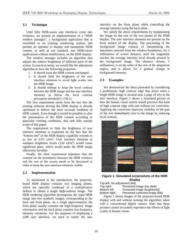
2.1 Technique
Until fully HDR-aware user interfaces come into existence, we present an implementation of a “HDR window manager”, a background application that is retrofitted to an existing windowing system, and permits an operator to display and manipulate HDR content, as well as use standard, non HDR-aware applications without modification, on the HDR display.
The window manager includes an algorithm that adjusts the relative brightness of different parts of the screen. In practical terms, we would like the adjustment algorithm to have the following properties:
1. It should leave the HDR content unchanged. 2. It should limit the brightness of the user
interface elements to avoid light scatter into the HDR image.
3. It should attempt to keep the local contrast between the HDR image and the user interface elements to below the local contrast perception threshold (~150:1).
The first requirement stems from the fact that the existing software driving the HDR display is already optimized to deliver the most accurate rendition of HDR content. Even though it would be possible to alter the presentation of the HDR content according to particular viewing conditions, that task falls outside scope of this paper.
The requirement to limit the brightness of user interface elements is explained by the fact that the “bottom end” of the HDR display capability extends to as low as 0.05 cd/m2. User interface elements at standard brightness levels (150 cd/m2) would cause significant glare, which would make the HDR image effectively invisible.
Finally, the third requirement stipulates that the contrast on the boundaries between the HDR windows and the rest of the screen needs to be decreased in order to keep the user interface elements visible.
2.2 Implementation
As mentioned in the introduction, the projector-based HDR display contains two imaging planes, which are optically combined in a multiplicative fashion to obtain a single high-contrast image. The HDR rendering algorithm decomposes the input HDR image into two synthetic images, corresponding to the back and front plane. As a rough approximation, the front plane usually contains the high-frequency image information and the back plane contains low-frequency intensity variations. For the purposes of displaying a LDR user interface, we need to render the user
interface on the front plane while controlling the average intensity using the back plane.
We satisfy the above requirements by manipulating the image on the rear of the two planes of the HDR display. The user interface elements are present on the front surface of the display. The processing of the background image consists of interpolating the intensities outward from the window boundaries, for 5 millimetres of screen distance, until the magnitude reaches the average intensity level already present in the background image. The distance chosen, 5 millimetres, is on the order of the size of the adaptation region, and it allows for a gradual change in background intensity.
2.3 Examples
We demonstrate the ideas presented by considering a problematic high contrast edge that arises when a bright HDR image is located near a page of text in the user interface. Figure 2 shows a simulated picture of how the human visual system would perceive this kind of high contrast edge with and without our correction. Applying the correction improves visibility of the part of the text immediately next to the image by reducing local contrast.
Figure 1. Simulated screenshots of the HDR display
Top left: No adjustment (flat) Top right: Perceived image (too dark) Bottom left: Corrected image (brightened) Bottom right: Perceived corrected image (flat)
Figure 1 shows images of the projector-based HDR display with and without running the algorithm, taken with a conventional digital camera. Note that these pictures cannot accurately reproduce the effects of light scatter in human vision.
IEEE VR 2005 Workshop on Emerging Display Technologies March 13, 2005
33

Figure 2. Appearance of text next to HDR
content (enlarged) In the top image, the non-HDR content was not
altered. The bottom image illustrates how text legibility was improved around the high-intensity parts of the image as a result of applying the algorithm.
3 Summary and Future Work
In this paper, we have drawn attention to unique challenges in displaying content on high dynamic range displays. We also presented an approach that addresses this challenge via automatically controlling the intensity of the non-foreground elements on the high dynamic range display in order to compensate for the effects of glare. The approach was described as a part of a window manager system, which adjusts the brightness of the surrounding content to assure that both the HDR content as well as the normal content are visible.
In our current implementation we ignored the content of the HDR window itself, assuming, mainly for simplicity, that it was “perfect” and was to be rendered as it was. For a more general implementation, we would have to consider the elements inside that window as well. For example, if one has instrument
palettes on top of the HDR content, the brightness of these palettes should be adjusted so that they are visible and do not adversely affect the main image (i.e. not too dark and not too bright respectively).
4 References
1. Debevec, P., Malik, J., “Recovering high dynamic range radiance maps from photographs”, Proc. of ACM SIGGRAPH ’97, pp. 369-378.
2. Durand, F., Dorsey, J., “Fast bilateral filtering for the display of high-dynamic-range images”, ACM Trans. Graph. (special issue SIGGRAPH 2002) 21, 3, pp. 257-266.
3. Kang, S. B., Uyttendaele, M.,Winder, S., Szeliski, R., “High dynamic range video”, ACM Trans. Graph. (special issue SIGGRAPH 2003) 22, 3 (2003), pp. 319-325.
4. Larson, G. W., Rushmeier, H., Piatko, C., “A visibility matching tone reproduction operator for high dynamic range scenes”, IEEE Trans. on Visualization and Computer Graphics, 3, 4 (1997), pp. 291-306.
5. Mann, S., Picard, R., “Being ‘undigital’ with digital cameras: Extending dynamic range by combining differently exposed pictures”, Tech. Rep. 323, M.I.T. Media Lab Perceptual Computing Section. Also appears, IS&T’s 48th annual conference, Cambridge, MA (1995).
6. Mitsunaga, T., Nayar, S. K., “Radiometric self calibration”, Proc. of IEEE CVPR (1999), pp. 472-479.
7. Pharr, M., Humphreys G., Physically Based Rendering : From Theory to Implementation, Morgan Kaufmann, 2004.
8. Robertson, M., Borman, S., Stevenson, R., “Dynamic range improvements through multiple exposures”, Proc. of International Conference on Image Processing (ICIP)’99, 1999, pp. 159-163.
9. H. Seetzen, W. Heidrich, W. Stuerzlinger, G. Ward, L. Whitehead, M. Trentacoste, A. Ghosh, A. Vorozcovs, “High Dynamic Range Display Systems”, SIGGRAPH 2004, 23, 3, ACM TOG, pp. 760-768.
10. Schlick, C., “Quantization techniques for visualization of high dynamic range pictures”, Proc. of Eurographics Workshop on Rendering ’94, 1994, pp. 7-20.
11. Tumblin, J., Turk, G., “LCIS: A boundary hierarchy for detail-preserving contrast reduction”, Proc. of ACM SIGGRAPH ’99, 1999, pp. 83-90.
12. Vos, J., “Disability glare - a state of the art report”, CIE Journal 3, 2, 1984, pp. 39-53.
IEEE VR 2005 Workshop on Emerging Display Technologies March 13, 2005
34
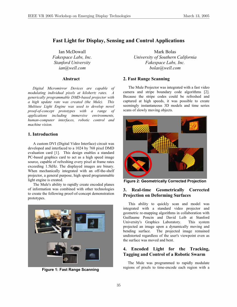
Fast Light for Display, Sensing and Control Applications
Ian McDowall Fakespace Labs, Inc. Stanford University
Mark Bolas University of Southern California
Fakespace Labs, Inc. [email protected]
Abstract
Digital Micromirror Devices are capable of
modulating individual pixels at kilohertz rates. A generically programmable DMD-based projector with a high update rate was created (the Mule). This Multiuse Light Engine was used to develop novel proof-of-concept prototypes with a range of applications including immersive environments, human-computer interfaces, robotic control and machine vision. 1. Introduction A custom DVI (Digital Video Interface) circuit was developed and interfaced to a 1024 by 768 pixel DMD evaluation card [1]. This design enables a standard PC-based graphics card to act as a high speed image source, capable of refreshing every pixel at frame rates exceeding 1.5kHz. The displayed images are binary. When mechanically integrated with an off-the-shelf projector, a general purpose, high speed programmable light engine is created. The Mule's ability to rapidly create encoded planes of information was combined with other technologies to create the following proof-of-concept demonstration prototypes.
Figure 1: Fast Range Scanning
2. Fast Range Scanning The Mule Projector was integrated with a fast video camera and stripe boundary code algorithms [2]. Because the stripe codes could be refreshed and captured at high speeds, it was possible to create seemingly instantaneous 3D models and time series scans of slowly moving objects.
Figure 2: Geometrically Corrected Projection
3. Real-time Geometrically Corrected Projection on Deforming Surfaces This ability to quickly scan and model was integrated with a standard video projector and geometric re-mapping algorithms in collaboration with Guillaume Poncin and David Leib at Stanford University's Graphics Laboratory. This system projected an image upon a dynamically moving and bending surface. The projected image remained undistorted regardless of the user's viewpoint even as the surface was moved and bent.
4. Encoded Light for the Tracking, Tagging and Control of a Robotic Swarm
The Mule was programmed to rapidly modulate regions of pixels to time-encode each region with a
IEEE VR 2005 Workshop on Emerging Display Technologies March 13, 2005
35
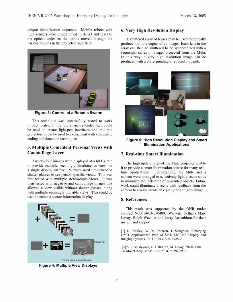
unique identification sequence. Mobile robots with light sensors were programmed to detect and react to the optical codes as the robots moved through the various regions in the projected light field.
Figure 3: Control of a Robotic Swarm
This technique was successfully tested to work
through water. In the future, such encoded light could be used to create light-pen interfaces and multiple projectors could be used to experiment with volumetric coding and detection techniques.
5. Multiple Coincident Personal Views with Camouflage Layer Twenty-four images were displayed at a 60 Hz rate to provide multiple, seemingly simultaneous views on a single display surface. Viewers used time-encoded shutter glasses to see person-specific views. This was first tested with multiple stereoscopic views. It was then tested with negative and camouflage images that allowed a view visible without shutter glasses, along with multiple seemingly invisible views. This could be used to create a secure information display.
Figure 4: Multiple View Displays
6. Very High Resolution Display A shuttered array of lenses may be used to optically produce multiple copies of an image. Each lens in the array can then be shuttered to be synchronized with a sequential series of images projected from the Mule. In this way, a very high resolution image can be produced with a correspondingly reduced bit depth.
Figure 5: High Resolution Display and Smart
Illumination Applications 7. Real-time Smart Illumination
The high update rates of the Mule projector enable it to provide a smart illumination source for many real-time applications. For example, the Mule and a camera were arranged to selectively light a scene so as to minimize the reflection of unwanted objects. Future work could illuminate a scene with feedback from the camera to always create an equally bright, gray image.
8. References
This work was supported by the ONR under contract N00014-03-C-0489. We wish to thank Marc Levoy, Ralph Wachter and Larry Rosenblum for their insight and support. [1] D. Dudley, W. M. Duncan, J. Slaughter, "Emerging DMD Applications" Proc of SPIE MOEMS Display and Imaging Systems, Ed. H. Urey, Vol. 4985-2 [2] S. Rusinkiewicz, O. Hall-Holt, M. Levoy, "Real-Time 3D Model Acquistion" Proc. SIGGRAPH 2002.
IEEE VR 2005 Workshop on Emerging Display Technologies March 13, 2005
36

Leveraging Hollywood Set Design Techniques to Enhance Ad Hoc Immersive Display Systems
Jarrell Pair Anton Treskunov Diane Piepol Institute for Creative Technologies University of Southern California
{pair, treskunov, piepol}@ict.usc.edu
Abstract
Over the past four years, the FlatWorld project [1] at the University of Southern California Institute for Creative Technologies has exploited ad hoc immersive display techniques to prototype virtual reality education and training applications. While our approach is related to traditional immersive projection systems such as the CAVE [2], our work draws extensively upon techniques widely used in Hollywood sets and theme parks. Our first display system, initially prototyped in 2001, enables wide area virtual environments in which participants can maneuver through simulated rooms, buildings, or streets. In 2004, we expanded our work by experimenting with transparent projection screens. To date, we have used this display technique for presenting life size interactive characters with a pseudo-holographic appearance.
1. Digital Flat Displays
Since the dawn of the film industry, movie sets have been constructed using modular panels called “flats”. Set designers use flats to create physical structures to represent a wide variety of places and activities. For example, a flat can be configured to appear as a room wall, a storefront, or a doorway.
FlatWorld is developing a reconfigurable system of “digital flats”. Using large-screen displays and real-time computer graphics technology, a single digital flat can appear as an interior room wall or an exterior building face. Functional doors and windows can also be added to digital flats by constructing physical props that are designed to fit and function in the flat system. For example, by placing a doorframe prop in front of a digital flat, a user can open a real door to view a computer generated view of the world outside.
The FlatWorld approach creates a “mixed reality” blurring the borders between the physical and the virtual elements of a scene. Theme park attractions successfully
employ this technique. For example, the enormously popular “Amazing Adventures of Spiderman” attraction at Universal Studios Islands of Adventure (in Orlando, Florida) uses stereoscopic projection screens tightly integrated with physical building facades, props, and other scenery. The props and screens successfully simulate a cityscape complete with deep alleys and vast building corridors.
Other related work is seen in the “Being There” project [3] at the University of North Carolina at Chapel Hill. In this system, walls of white styrofoam blocks are arranged to reproduce the basic layout of a room. Imagery is front projected onto the styrofoam blocks making these surfaces appear as textured walls with virtual windows and doors.
A single room FlatWorld system was constructed in November 2001. This prototype consists of two digital flats and two real walls (Figure 1). Movable door, window, and broken wall props can reconfigure the room’s appearance. The physical walls and props were constructed by Paramount Studios. The projection walls are coated 3/4” acrylic sheets. A demonstration was developed using real time stereoscopic graphics (Figure 2), immersive audio, and a number of other effects.
Imagery for each digital flat is provided by a custom stereoscopic rear projection system. Projectors are mounted with passive polarizing filters and driven by PC’s. The system’s real time audiovisual content was developed using OpenGL and the DirectSound3D programming library. Strobe lights, overhead fans, and other multi-sensory effects devices are controlled using the X10 home automation protocol.
In 2005, we will expand our prototype system to simulate a multi-room space with both interior and exterior environments. We will fabricate the system’s components as a series of modular units to enable rapid physical and electronic setup. Our goal is a system that can be dismantled and moved among multiple sites.
IEEE VR 2005 Workshop on Emerging Display Technologies March 13, 2005
37

Figure 1. User viewing exterior virtual world through a physical door.
2. Transparent Screen Projection System
In 2004, we developed a system which can present life-size, interactive virtual characters with a pseudo-holographic appearance (Figure 3). This holographic illusion effect is created by projecting high-resolution real-time graphics onto specialized transparent optical film. Users interact with the character using a speech recognition engine linked to a statistical classifier which generates the character’s responses.
3. Acknowledgements
This paper was developed with funds of the Department of the Army under contract number DAAD 19-99-D-0046. Any opinions, findings and conclusions or recommendations expressed in this paper are those of the authors and do not necessarily reflect the views of the Department of the Army.
4. References
[1] Pair, Jarrell, Ulrich Neumann, Diane Piepol, and Bill Swartout. "FlatWorld: Combining Hollywood Set Design Techniques with VR." IEEE Computer Graphics and Applications. January/February 2003, pp. 12-15.
[2] Cruz-Neira, C., D. Sandin, T. DeFanti. “Surround- Screen Projection-Based Virtual Reality: The Design and Implementation of the CAVE.” In Computer Graphics Proceedings, Annual Conference Series, ACM SIGGRAPH, New York 1993. pp.135-142.
[3] Kok-Lim Low, Greg Welch, Anselmo Lastra, Henry Fuchs. “Life-Sized Projector-Based Dioramas.” Proceedings of the ACM Symposium on Virtual Reality Software and Technology. November 2001, pp. 93-101.
Figure 3: Interactive character projection onto a transparent screen creates the illusion of a hologram.
Figure 2. Artistic depiction of stereoscopic display in the FlatWorld System.
IEEE VR 2005 Workshop on Emerging Display Technologies March 13, 2005
38

IEEE VR 2005 Workshop on Emerging Display Technologies March 13, 2005
16:00–17:00 Open Panel Discussion
Rendering for Emerging Display Technologies . . . . . . . . . . . . . . . . . . . . . . . . . . . . . . . . . . . . . . . . . . . . . . . . . . . . . . . . . . .39T. Funkhouser, H. Kunz, D. Reiners, P. Slusallek, and R. Yang
39

IEEE VR 2005 Workshop on Emerging Display Technologies March 13, 2005
(This page intentionally left blank.)
40
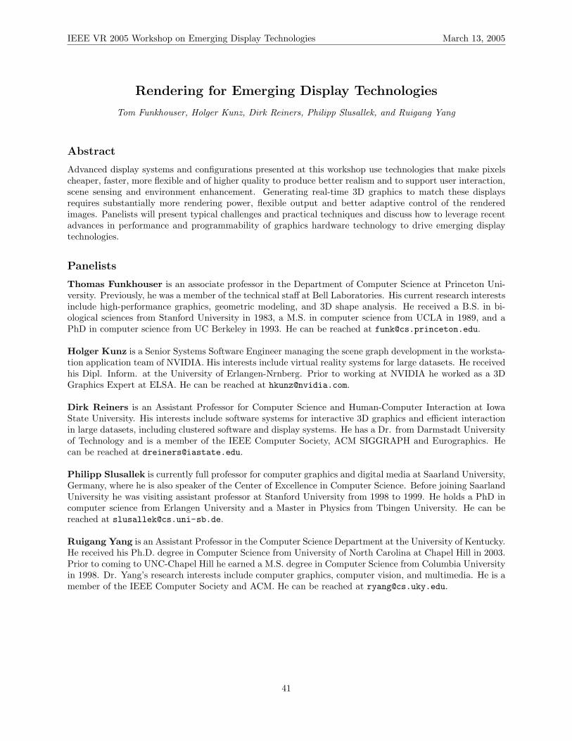
IEEE VR 2005 Workshop on Emerging Display Technologies March 13, 2005
Rendering for Emerging Display Technologies
Tom Funkhouser, Holger Kunz, Dirk Reiners, Philipp Slusallek, and Ruigang Yang
Abstract
Advanced display systems and configurations presented at this workshop use technologies that make pixelscheaper, faster, more flexible and of higher quality to produce better realism and to support user interaction,scene sensing and environment enhancement. Generating real-time 3D graphics to match these displaysrequires substantially more rendering power, flexible output and better adaptive control of the renderedimages. Panelists will present typical challenges and practical techniques and discuss how to leverage recentadvances in performance and programmability of graphics hardware technology to drive emerging displaytechnologies.
Panelists
Thomas Funkhouser is an associate professor in the Department of Computer Science at Princeton Uni-versity. Previously, he was a member of the technical staff at Bell Laboratories. His current research interestsinclude high-performance graphics, geometric modeling, and 3D shape analysis. He received a B.S. in bi-ological sciences from Stanford University in 1983, a M.S. in computer science from UCLA in 1989, and aPhD in computer science from UC Berkeley in 1993. He can be reached at [email protected].
Holger Kunz is a Senior Systems Software Engineer managing the scene graph development in the worksta-tion application team of NVIDIA. His interests include virtual reality systems for large datasets. He receivedhis Dipl. Inform. at the University of Erlangen-Nrnberg. Prior to working at NVIDIA he worked as a 3DGraphics Expert at ELSA. He can be reached at [email protected].
Dirk Reiners is an Assistant Professor for Computer Science and Human-Computer Interaction at IowaState University. His interests include software systems for interactive 3D graphics and efficient interactionin large datasets, including clustered software and display systems. He has a Dr. from Darmstadt Universityof Technology and is a member of the IEEE Computer Society, ACM SIGGRAPH and Eurographics. Hecan be reached at [email protected].
Philipp Slusallek is currently full professor for computer graphics and digital media at Saarland University,Germany, where he is also speaker of the Center of Excellence in Computer Science. Before joining SaarlandUniversity he was visiting assistant professor at Stanford University from 1998 to 1999. He holds a PhD incomputer science from Erlangen University and a Master in Physics from Tbingen University. He can bereached at [email protected].
Ruigang Yang is an Assistant Professor in the Computer Science Department at the University of Kentucky.He received his Ph.D. degree in Computer Science from University of North Carolina at Chapel Hill in 2003.Prior to coming to UNC-Chapel Hill he earned a M.S. degree in Computer Science from Columbia Universityin 1998. Dr. Yang’s research interests include computer graphics, computer vision, and multimedia. He is amember of the IEEE Computer Society and ACM. He can be reached at [email protected].
41