Worksheet Report Sample Using Excel - Primatech€¦ · XLS file · Web view ·...
27
W Printed: June 21, 2002, 2:34 PM Company: Safetech Location: Princeton, NJ Facility: Princeton PHA Method: HAZOP PHA Type: Initial Process: File Description: Chlorine Handling Date: Process Description: Chemicals: Purpose: Scope: Objectives: Project Notes: Filters: None PHAWorks by Primatech Inc. Page: 1 Company: Safetech Facility: Princeton (1) 07/02/00 0 (1) Chlorine rail car CLC/01-07-66 Pressure GW DEVIATION CAUSES More Higher Pressure 1. Fire exposure Node 1: Chlorine rail car, Parameter: Pressure Node 1: Chlorine rail car, Parameter: Composition Node 1: Chlorine rail car, Parameter: Level Node 2: Cl2 liquid to vaporizer, Parameter: Flow Node 2: Cl2 liquid to vaporizer, Parameter: Pressure Node 2: Cl2 liquid to vaporizer, Parameter: Composition Node 3: Cl2 vaporizer, Parameter: Flow Node 3: Cl2 vaporizer, Parameter: Pressure Table of contents Session: Revision: Node: Drawings: Parameter: Intention: psig. Target pressure is 125 psig.
Transcript of Worksheet Report Sample Using Excel - Primatech€¦ · XLS file · Web view ·...

Index
Worksheet - Cover Page
Printed: June 21, 2002, 2:34 PMCompany: SafetechLocation: Princeton, NJFacility: Princeton
PHA Method: HAZOPPHA Type: InitialProcess:File Description: Chlorine HandlingDate:Process Description:Chemicals:Purpose:Scope:Objectives:Project Notes:Filters: None
PHAWorks by Primatech Inc.
Worksheet
Page: 1Company: SafetechFacility: Princeton
(1) 07/02/000
(1) Chlorine rail carCLC/01-07-66Pressure
GW DEVIATIONMore Higher Pressure
Node 1: Chlorine rail car, Parameter: PressureNode 1: Chlorine rail car, Parameter: CompositionNode 1: Chlorine rail car, Parameter: LevelNode 2: Cl2 liquid to vaporizer, Parameter: FlowNode 2: Cl2 liquid to vaporizer, Parameter: PressureNode 2: Cl2 liquid to vaporizer, Parameter: CompositionNode 3: Cl2 vaporizer, Parameter: FlowNode 3: Cl2 vaporizer, Parameter: Pressure
Table of contentsSession: Revision: Node: Drawings: Parameter:
Intention: Normal operation is 100 - 150 psig. Target pressure is 125 psig.

More Higher Pressure
Less Lower Pressure
(1) 07/02/000
(1) Chlorine rail carCLC/01-07-66Composition
Chlorine with less than 5 ppm moisture.GW DEVIATION
Other Than Other Than Composition
As Well As As Well As Composition (contamination)
(1) 07/02/000
(1) Chlorine rail carCLC/01-07-66Level
GW DEVIATIONNo No Level
More Higher Level
PHAWorks by Primatech Inc.
Worksheet
Page: 2
Table of contentsSession: Revision: Node: Drawings: Parameter:
Intention:
Table of contentsSession: Revision: Node: Drawings: Parameter:
Intention:
Normal railcar liquid level varies between a maximum of 80 % of capacity to as empty as practical.

Company: SafetechFacility: Princeton
(1) 07/02/000
(2) Cl2 liquid to vaporizerCLC/01-07-66Flow
GW DEVIATIONNo No Flow
Table of contentsSession: Revision: Node: Drawings: Parameter:
Intention:
Flow approximately 1 - 5 lbs/min of liquid chlorine, at 100- 150 psig, from the railcar to the vaporizer.

No No Flow

No No Flow
Less Less Flow
More Flow

Less
More Flow
Reverse Reverse Flow
Other Than Other Than Flow

(1) 07/02/000
(2) Cl2 liquid to vaporizerCLC/01-07-66Pressure
GW DEVIATIONMore Higher Pressure
Less Lower Pressure
(1) 07/02/000
(2) Cl2 liquid to vaporizerCLC/01-07-66CompositionChlorine to specification
GW DEVIATION
Table of contentsSession: Revision: Node: Drawings: Parameter:
Intention: Normal operating pressure is approximately 100-145 psig.
Table of contentsSession: Revision: Node: Drawings: Parameter: Intention:

As Well As As Well As Composition
PHAWorks by Primatech Inc.
Worksheet
Page: 3Company: SafetechFacility: Princeton
(1) 07/02/000
(3) Cl2 vaporizerCLC/01-07-66Flow
GW DEVIATIONNo No Flow
As Well As As Well As Flow
(1) 07/02/000
(3) Cl2 vaporizerCLC/01-07-66Pressure
Vaporizer is intended to operate at 3 atm.GW DEVIATION
More Higher Pressure
Table of contentsSession: Revision: Node: Drawings: Parameter:
Intention: Vaporize 100-150 pounds per hour. Target is 125.
Table of contentsSession: Revision: Node: Drawings: Parameter:
Intention:

More Higher Pressure
Less Lower Pressure
PHAWorks by Primatech Inc.

Index
Worksheet - Cover Page
Filters: None
Worksheet
CAUSES CONSEQUENCES1. Fire exposure
2. High ambient temperature
1.1. Potential overpressurization of rail car resulting in release of chlorine.
1.2. Potential rupture of the rail car if the rail car relief valve fails.
2.1. Potential increase in pressure. Not likely to approach rated pressure of rail car.

2. High ambient temperature
3. Relief valve RV-25 fails open
4. Empty rail car 4.1. Delay in treating5. Sudden change in ambient temperature
CAUSES CONSEQUENCES
CAUSES CONSEQUENCES1. Rail car received empty 1.1. Delay in treating2. Leak in rail car or attached piping
3. Supplier overloads
Worksheet
2.1. Potential increase in pressure. Not likely to approach rated pressure of rail car.
3.1. Potential exposure of personnel and potential offsite impact
5.1. Potential for too low flow to the treatment system
1. Supplier loads rail car with incorrect material
1.1. Consequences will depend upon what other materials could be delivered in rail cars.
2. Rail car padded with incorrect material (e.g. moist air) by supplier
2.1. Moisture with chlorine will cause accelerated corrosion of system piping
2.2. Consequences will depend upon what other materials could be delivered in rail cars
2.1. Potential exposure of personnel and potential offsite impact
3.1. Potential overpressure of rail car due to thermal expansion of material

CAUSES CONSEQUENCES1. Control valve CV-32 fails closed 1.1. Interruption to production operation due to
deviation of Cl2 flow from setpoint causing control system to shut down process
1.2. Potential overpressure of Cl2 piping if liquid-filled, closed piping heats up
2. Control system incorrectly activates shutdown for "rupture" condition
2.1. Potential overpressure of Cl2 piping if liquid filled, closed piping heats up

4. Manual block valve is accidentally closed
5. Filter plugged
6. Micromotion meter plugged
7. Dip pipe (in railcar) plugged
8. Excess flow valve closed
9. Line or flex hose failure
3. Control valve closes due to incorrect signal or setting
3.1. Interruption to production operation due to deviation of Cl2 flow from setpoint causing control system to shut down process
4.1. Interruption to production operation due to deviation of Cl2 flow from setpoint causing control system to shut down process
5.1. Interruption to production operation due to deviation of Cl2 flow from setpoint causing control system to shut down process
6.1. Interruption to production operation due to deviation of Cl2 flow from setpoint causing control system to shut down process
7.1. Interruption to production operation due to deviation of Cl2 flow from setpoint causing control system to shut down process
8.1. Interruption to production operation due to deviation of Cl2 flow from setpoint causing control system to shut down process
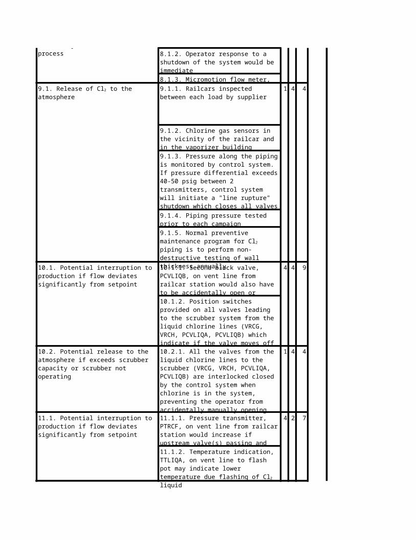
9.1. Release of Cl2 to the atmosphere
9. Line or flex hose failure
12. Leak
14. Higher than normal pressure in rail car
9.1. Release of Cl2 to the atmosphere
10. Block valve (VRCG/H, PCVLIQA) to vent scrubber system open or passing
10.1. Potential interruption to production if flow deviates significantly from setpoint
10.2. Potential release to the atmosphere if exceeds scrubber capacity or scrubber not operating
11. Partial pluggage of any component or partially closed valve
11.1. Potential interruption to production if flow deviates significantly from setpoint
12.1. Release of Cl2 to the atmosphere
13. N2 pressurization valve, VRCC/VRCD, opens during padding of railcar, and manual block on tubing left open, displacing liquid Cl2 in line with N2
13.1. Potential erratic flow due to presence of N2 in system. Potential overchlorination of product due to surge of chlorine ahead of N2. Impact on product quality. Potential overloading of scrubber
14.1. Potential erratic flow due to presence of N2 in system. Potential overchlorination of product due surge of chlorine ahead of N2. Impact on product quality. Potential overloading of scrubber

14. Higher than normal pressure in rail car
16. Sudden clearing of a blockage
19. Failure of liquid chlorine line or flex hose
20. Failure of rupture disk on liquid line
14.1. Potential erratic flow due to presence of N2 in system. Potential overchlorination of product due surge of chlorine ahead of N2. Impact on product quality. Potential overloading of scrubber
15. Flow control valve, FCVGASA, opens wide due to incorrect signal or setting
15.1. Potential erratic flow due presence of N2 in system. Potential overchlorination of product due surge of chlorine ahead of N2. Impact on product quality. Potential overloading of scrubber
16.1. Potential erratic flow due to presence of N2 in system. Potential overchlorination of product due surge of chlorine ahead of N2. Impact on product quality. Potential overloading of scrubber due to surge of chlorine
17. Blockage of the system downstream of the vaporizer
17.1. Vaporization of liquid in vaporizer will increase vaporizer pressure pushing liquid Cl2 back to rail car
17.2. No flow, sensed by FICGASA, will initiate a shutdown. Will close VLIQB and open VGASA to vent vaporizer to the scrubber
18. Rupture of the N2 pressurization line at the rail car when padding the rail car
18.1. Release of Cl2 to atmosphere
19.1. Release of Cl2 to the atmosphere
20.1. Some flow of chlorine to the expansion tanks
20.2. Potential loss of expansion capacity if rupture disk released, expansion tanks filled and pressure rise in expansion tanks not observed by operator.

CAUSES CONSEQUENCES1. Fire exposure
2. Steam exposure
3. High ambient temperature
5. Leak in rail car or relief valve fails open
6. Empty rail car 6.1. Delay in treating7. Sudden change in ambient temperature
CAUSES CONSEQUENCES
1.1. Potential overpressurization of rail car resulting in release of chlorine.
1.2. Potential rupture of the rail car if the rail car relief valve fails.
2.1. Potential overheating if broken steam line discharges on chlorine line
3.1. Potential increase in pressure. Not likely to approach rated pressure of rail car
4. Change in ambient temperature after padding rail car
4.1. Potential for too low flow to the treatment system
5.1. Potential exposure of personnel and potential offsite impact
7.1. Potential for too low flow to the treatment system

1. Water, or other agents, in line after cleaning
Worksheet
CAUSES CONSEQUENCES1. Exit valve is in off position 1.1. Overpressurization of vaporizer
2. Entrance valve is in off position 2.1. Product down time2.2. Excessive wear on pumps
3.1. Impure product
4.1. Impure product
4.2. Side reaction causing exotherm.
CAUSES CONSEQUENCES1. Exit line from vaporizer plugged
1.2. Pressure build up in vaporizer
1.1. Potential for accelerated corrosion of the piping
2. Use of non- compatible materials, such as hydrocarbon- containing greases, during maintenance of system
2.1. Potential reaction possibly causing accelerated corrosion, fire or contaminants affecting product quality
3. N2 purge stream valve is open
4. Impure Cl2 feed
1.1. Failure to provide adequate supply to reactor

2.1. Pressure build up in vaporizer
3. Supply line plugged
4. Rupture in line exiting the vaporizer 4.1. Release of chlorine to atmosphere
4.2. Loss of reactant5. Leak in vaporizer
2. Chlorine supply line has a greater flow rate than designed
3.1. Loss of productivity due to low chlorine supply to reactor
5.1. Release of Cl2 to atmosphere

Index
Worksheet - Cover Page
Worksheet
SAFEGUARDS S L R REF# RECOMMENDATIONS BY1.1.1. Rail cars provided with relief valve. 1 4 4 :No recommendations
1.1.2. Rail cars insulated1 5 5 :No recommendations
2.1.1. Rail cars insulated 5 1 5 :No recommendations
1.2.1. Location of rail car minimizes likelihood of exposure.

5 1 5 :No recommendations
2.1.3. Pressure indicator, PI-1.1 4 4 PWP
3.1.2. Pressure indicator, PI-1.4.1.1. Rail car is weighed upon receipt 5 3 9 :No further recommendations5.1.1. Rail cars insulated 5 2 8 :No further recommendations
SAFEGUARDS S L R REF# RECOMMENDATIONS BY1.1.1. Analysis of shipment by supplier. 3 4 8 DSC
2.1.1. Analysis of shipment by supplier. 3 4 8 :No further recommendations
2.2.1. As for 2.1.1 3 4 8 :No further recommendations
SAFEGUARDS S L R REF# RECOMMENDATIONS BY1.1.1. Rail car is weighed upon receipt 5 4 10 :No recommendations
3 4 8 :No recommendations
3.1.1. Rail car weighed upon receipt 3 4 8 LSS
Worksheet
2.1.2. Location of rail car minimizes likelihood of exposure.
3.1.1. Railcar emergency leak patch kit is available on site.
3.1.1. Consider conducting a failure modes and effects analysis (FMEA) of a typical pressure relief valve.
1.1.1. Consider changing the SOP to require a certificate of analysis be received with each rail car and be checked before accepting the rail car.
2.1.1. Chlorine gas sensors around rail car unloading station
2.1.2. Emergency C kit available for rail car leaks
3.1.1. *Verify the scales are calibrated correctly

SAFEGUARDS S L R REF# RECOMMENDATIONS BY4 4 9 :No recommendations
1.1.4. Micromotion flow meter, FTLIQA3 4 8 :No recommendations
- VLIQA and VLIQB
- VRCA2 and VRCL- VRCB2 and VRCM- VRCL/M and VLIQA- VLIQB and PCVGASC
3 4 8 LDS
- VLIQA and VLIQB
JBS
2.1.4. Micromotion flow meter, FTLIQA
1.1.1. Failing closed, or accidentally closing, a single valve will not result in overpressure since line is open to either end
1.1.2. Operator response to a shutdown of the system would be immediate
1.1.3. Limit switch provided on each valve which will indicate the valve is closed
1.2.1. All valves (ball valves) in liquid Cl2 service are provided with a port to vent the ball cavity
1.2.2. Rupture disk discharging to expansion tanks are provided for the section of the piping between
- PCVGASC and PCVGASB (downstream of vaporizer)
1.2.3. Pressure transmitters provided on potentially trapped sections of piping between:
2.1.1. Rupture disk discharging to expansion tanks are provided for the section of the piping between
2.1.1. *Investigate the design of the rupture disks and expansion tanks and the pressure setting (375 psig) of the rupture disk
- PCVGASC and PCVGASB (downstream of vaporizer)
2.1.2. Failing closed, or accidentally closing, a single valve will not result in overpressure since line is open to either end
2.1.2. *Verify Chlorine Institute requirements for venting valves with design of existing valves
2.1.3. Limit switch provided on each valve which will indicate the valve is closed

4 4 9 :No further recommendations
3.1.4. Micromotion flow meter, FTLIQA4 4 9 :No further recommendations
4.1.4. Micromotion flow meter, FTLIQA4 2 7 :No further recommendations
5.1.2. Micromotion flow meter, FTLIQA4 2 7 :No further recommendations
4 2 7 :No further recommendations
7.1.2. Micromotion flow meter, FTLIQA4 4 9 :No further recommendations
8.1.3. Micromotion flow meter, FTLIQA1 4 4 LDS
TLK
3.1.1. Failing closed, or accidentally closing, a single valve will not result in overpressure since line is open to either end
3.1.2. Operator response to a shutdown of the system would be immediate
3.1.3. Limit switch provided on each valve which will indicate the valve is closed
4.1.1. Failing closed, or accidentally closing, a single valve will not result in overpressure since line is open to either end
4.1.2. Operator response to a shutdown of the system would be immediate
4.1.3. Limit switch provided on each valve which will indicate the valve is closed
5.1.1. Operator response to a shut down of the system would be immediate
6.1.1. Operator response to a shut down of the system would be immediate
6.1.2. Pressure transmitters before and after the meter
7.1.1. Operator response to a shut down of the system would be immediate
8.1.1. Failing closed, or accidentally closing, a single valve will not result in overpressure since line is open to either end
8.1.2. Operator response to a shutdown of the system would be immediate
9.1.1. Railcars inspected between each load by supplier
9.1.1. Consider alternatives to the present hanger arrangements to allow total insulating of the piping while minimizing external corrosion of the piping.
9.1.2. Chlorine gas sensors in the vicinity of the railcar and in the vaporizer building
9.1.2. Consider whether alternative materials of construction are practical which will provide better internal and external corrosion resistance

1 4 4
TLK
4 4 9 :No further recommendations
1 4 4 :No further recommendations
4 2 7 :No further recommendations
1 4 4 PWP
4 4 9 :No recommendations
4 4 9 :No recommendations
9.1.2. Consider whether alternative materials of construction are practical which will provide better internal and external corrosion resistance
9.1.3. Pressure along the piping is monitored by control system. If pressure differential exceeds 40-50 psig between 2 transmitters, control system will initiate a "line rupture" shutdown which closes all valves on the liquid Cl2 piping
9.1.4. Piping pressure tested prior to each campaign
9.1.5. Normal preventive maintenance program for Cl2 piping is to perform non-destructive testing of wall thickness annually
10.1.1. Second block valve, PCVLIQB, on vent line from railcar station would also have to be accidentally open or passing
10.1.2. Position switches provided on all valves leading to the scrubber system from the liquid chlorine lines (VRCG, VRCH, PCVLIQA, PCVLIQB) which indicate if the valve moves off the fully closed position.
10.2.1. All the valves from the liquid chlorine lines to the scrubber (VRCG, VRCH, PCVLIQA, PCVLIQB) are interlocked closed by the control system when chlorine is in the system, preventing the operator from accidentally manually opening the valve from the console.
11.1.1. Pressure transmitter, PTRCF, on vent line from railcar station would increase if upstream valve(s) passing and downstream closed
11.1.2. Temperature indication, TTLIQA, on vent line to flash pot may indicate lower temperature due flashing of Cl2 liquid
12.1.1. Chlorine sensor provided near atmospheric vent from scrubber system
12.1.1. Review the best available means for periodic testing and/or examination of the chlorine liquid piping system to ensure the system integrity
12.1.2. Control valve on Cl2 gas flow to reactor, FCVGASA, will open to attempt to maintain set flow to reactor
13.1.1. Flow indication and control (FICGASA) on chlorine flow to reactor will throttle to maintain set flow
13.1.2. Position indicators on N2 valves (VRCC, VRCD) which indicates whenever the valve is off normally closed position.
14.1.1. Backup manual valve on N2 line is normally closed except when pressure testing the piping.

14.1.2. Pressure monitoring of pipeline
4 4 9 :No recommendations
4 4 9 :No recommendations
4 2 7 :No recommendations
4 2 7 :No recommendations
4 2 7 :No recommendations
1 5 5 :No recommendations
1 5 5 :No recommendations
1 5 5 :No recommendations
4 5 10 :No recommendations
15.1.1. Independent flow indication, FTLIQA, to allow operator to verify flow control reading
16.1.1. Flow indication and control (FICGASA) on chlorine flow to reactor will throttle to maintain set flow
17.1.1. Chlorine line is open back to the rail car preventing excessive pressure buildup
17.1.2. Pressure indication on vaporizer outlet, PTGASA
17.2.1. Flow indicators, FICGASA and FTLIQA, will indicate no flow
17.2.2. Line upstream of VLIQB is open to the railcar
18.1.1. Piping downstream of vaporizer is vented to the scrubber thru VGASA
18.1.2. Rupture disk and relief valve on vaporizer , discharging to catch pot T-22, if blockage is between vaporizer and VGASA. Additional capability to manually vent lines thru VGASC or PCVLIQA
19.1.1. Piping downstream of vaporizer is vented to the scrubber thru VGASA
19.1.2. Rupture disk and relief valve on vaporizer , discharging to catch pot T-22, if blockage is between vaporizer and VGASA. Additional capability to manually vent lines thru VGASC or PCVLIQA
20.1.1. Pressure indicator, PTLIQD, on line to expansion tanks
20.2.1. Chlorine gas sensors in the vicinity of the railcar and in the vaporizer building
20.2.2. Pressure along the piping is monitored by control system. If pressure differential exceeds 40-50 psig between 2 transmitters, control system will initiate a "line rupture" shutdown which closes all valves on the liquid Cl2 piping
20.2.3. Piping pressure tested prior to each campaign

SAFEGUARDS S L R REF# RECOMMENDATIONS BY1 5 5 :No further recommendations
1.1.3. Rail cars insulated1.2.1. Rail cars provided with relief valve 1 5 5 :No further recommendations
1.2.3. Pressure indicator, PI-13 4 8 :No recommendations
2.1.3. Rail cars insulated5 1 5 :No further recommendations
3.1.3. Rail cars insulated5 2 8 :No further recommendations
4.1.3. Pressure indicator, PI-14.1.4. Rail cars insulated
1 5 5 :No further recommendations
5.1.2. Pressure indicator, PI-16.1.1. Rail car weighed upon receipt 4 4 9 :No further recommendations7.1.1. Rail car weighed upon receipt 4 3 8 :No further recommendations
SAFEGUARDS S L R REF# RECOMMENDATIONS BY
1.1.1. Chlorine line insulated except at hangers
1.1.2. Chlorine line open to railcar and/or vaporizer
1.2.2. Location of rail car minimizes likelihood of exposure
2.1.1. Chlorine line insulated except at hangers
2.1.2. Chlorine line open to railcar and/or vaporizer
3.1.1. Chlorine line insulated except at hangers
3.1.2. Chlorine line open to railcar and/or vaporizer
4.1.1. Chlorine line insulated except at hangers
4.1.2. Chlorine line open to railcar and/or vaporizer
5.1.1. Railcar emergency leak patch kit is available on site

3 4 8 LDS
3 4 8 TLK
Worksheet
SAFEGUARDS S L R REF# RECOMMENDATIONS BY1.1.1. Relief valves on vessel 3 4 8 LSS
2.1.1. None 4 4 9 :No further recommendations3 4 8 :No further recommendations
4 4 9 LSS
4 4 9 :No further recommendations
3 4 8 :No further recommendations
SAFEGUARDS S L R REF# RECOMMENDATIONS BY1.1.1. Low flow alarm present 4 2 7 :No further recommendations
4 2 7 :No further recommendations
1.1.1. Normal procedure for cleaning includes blowing the system dry with N2 after cleaning
1.1.1. Consider means of cleaning the chlorine piping system which do not involve the use of water or incompatible materials
1.1.2. Training of maintenance personnel working on chlorine system
2.1.1. Normal procedure for cleaning includes blowing the system dry with N2 after cleaning
2.1.1. Consider modifying the training program for maintenance personnel who may work on the chlorine system to include coverage of incompatible materials
2.1.2. Training of maintenance personnel working on chlorine system
1.1.1. *Verify relief valves undergo periodic testing
2.2.1. Pumps have autoshutoff switches to prevent overheating
3.1.1. Feed is tested when it is unloaded from rail car
3.1.1. Consider updating SOP to include a valve configuration flow sheet
4.1.1. Feed is tested when it is unloaded from rail car
1.2.1. Pressure rating on vaporizer exceeds that of the supply tanks

3 4 8 :No further recommendations
3.1.1. Low flow alarm present. 4 2 7 LSS
4.1.1. Chlorine gas sensors in the area 1 5 5 JBS
4 5 10 :No further recommendations5.1.1. Chlorine gas sensors in the area 1 5 5 LDS
2.1.1. Pressure rating on vaporizer exceeds that of the supply tanks
3.1.1. *Check to see if this has ever been a problem
4.1.1. Consider installing an automatic chlorine source shutdown if the vaporizer pressure drops below 1.5 atm.
5.1.1. Consider implementing a periodic check of vaporizer to ensure there are no pressure leaks