Working Towards the Design of Safer Ships and Pragmatic...
15
155 WORKING TOWARDS THE DESIGN OF SAFER SHIPS AND PRAGMATIC SUPPORT FOR SAFE OPERATION Heike Cramer Prof. Dr. Stefan Kr¨ uger J¨ urgen Sanslzon Flensburger Schiffbau– Technische Universit¨ at See–Berufsgenossenschaft Gesellschaft Hamburg–Harburg (Germany) (Germany) (Germany) ABSTRACT Recent examples of (dynamic) intact stability problems and research show that the current rules and regulations – which are based on empirical criteria related to the calm water lever arm curve – do not and can not represent todays vessels sufficiently well. Thus in ship design and approval there is a strong need for new and more reliable means of assessment. At IMO-SLF the Intact Stability Code is currently under revision and there is a strong demand to include the IMO MSC/Circ. 707 also, in order to provide more appropriate guidance for ship operation. In this paper some examples will be given how numerical motion simulations and appropriate evaluation methodologies which were and are developed within the German BMBF-funded projects Roll-S and SinSee can support • the design and approval of safer ships • the revision of rules and regulations and • the compilation of general and ship specific guidance manuals. 1 INTRODUCTION All three ship design, ship approval and ship op- eration determine the safety of a vessel in rough conditions. Now while designing as much sea- worthiness as economically feasible into a ship from the start provides the best basis for safe operation, it alone is not enough. Experience from ship operation shows, that the safety of a vessel and its crew relies strongly on the abil- ity of the crew to judge the vessels performance and its limits. Consequently it is necessary to improve both: • the understanding of ship dynamics and its importance for the ship’s safety in the ship design process as well as • the support given to the crew for decision making to avoid dangerous conditions. Furthermore internationally binding rules and regulations have to define the required mini- mum safety standard and should allow for a comprehensive evaluation of a ship’s perfor- mance with respect to safety. Traditionally the ship design and approval pro- cess is based on the application of empiri- cal formulae and the past experience of the naval architects. This approach proved to be a very fast and efficient way of ship design and approval in the past, especially as other ap- proaches were unavailable for most problems. In today’s highly competitive environment ship designs change very rapidly. Especially in areas where the design process is supported by ad- vanced design and analysis tools which are avail- able for application worldwide today, e.g. CFD-
Transcript of Working Towards the Design of Safer Ships and Pragmatic...

155
WORKING TOWARDS THE DESIGN OF SAFER SHIPS ANDPRAGMATIC SUPPORT FOR SAFE OPERATION
Heike Cramer Prof. Dr. Stefan Kruger Jurgen SanslzonFlensburger Schiffbau– Technische Universitat See–Berufsgenossenschaft
Gesellschaft Hamburg–Harburg(Germany) (Germany) (Germany)
ABSTRACT
Recent examples of (dynamic) intact stability problems and research show that the current rulesand regulations – which are based on empirical criteria related to the calm water lever arm curve –do not and can not represent todays vessels sufficiently well. Thus in ship design and approval thereis a strong need for new and more reliable means of assessment. At IMO-SLF the Intact StabilityCode is currently under revision and there is a strong demand to include the IMO MSC/Circ. 707also, in order to provide more appropriate guidance for ship operation.
In this paper some examples will be given how numerical motion simulations and appropriateevaluation methodologies which were and are developed within the German BMBF-funded projectsRoll-S and SinSee can support
• the design and approval of safer ships
• the revision of rules and regulations and
• the compilation of general and ship specific guidance manuals.
1 INTRODUCTION
All three ship design, ship approval and ship op-eration determine the safety of a vessel in roughconditions. Now while designing as much sea-worthiness as economically feasible into a shipfrom the start provides the best basis for safeoperation, it alone is not enough. Experiencefrom ship operation shows, that the safety of avessel and its crew relies strongly on the abil-ity of the crew to judge the vessels performanceand its limits. Consequently it is necessary toimprove both:
• the understanding of ship dynamics andits importance for the ship’s safety in theship design process as well as
• the support given to the crew for decisionmaking to avoid dangerous conditions.
Furthermore internationally binding rules andregulations have to define the required mini-mum safety standard and should allow for acomprehensive evaluation of a ship’s perfor-mance with respect to safety.
Traditionally the ship design and approval pro-cess is based on the application of empiri-cal formulae and the past experience of thenaval architects. This approach proved to be avery fast and efficient way of ship design andapproval in the past, especially as other ap-proaches were unavailable for most problems.In today’s highly competitive environment shipdesigns change very rapidly. Especially in areaswhere the design process is supported by ad-vanced design and analysis tools which are avail-able for application worldwide today, e.g. CFD-
156
or FE-analysis used either by the yards them-selves or being accessed through subsuppliers.Consequently a lot of the traditional commonlyused empirical formulae, some of which are alsothe basis of current rules and regulations, fail todeliver reliable answers. This is one of the rea-sons for current examples of dynamic intact sta-bility problems, e.g. large containerships beingsusceptible to parametric rolling and/or pureloss of stability, ferries and cruise ships sufferingfrom very short roll periods and/or high accel-erations and the like.
Focussing on resonance problems and especiallythe phenomena of parametric excitation as ap-plication example, this paper aims at showing
1. how the safety of ships regarding intactstability and seaworthiness can be signifi-cantly improved when the ship’s dynamicbehaviour is studied using direct calcula-tion methods early within the ship’s de-sign process
2. practical examples, how based on the re-sults of first principle based studies, use-ful and pragmatic aids for ship operationcan be developed, which then can providea sound base for decision making, i.e. toidentify and avoid dangerous conditions atsea
3. how these methods for direct calculationsand experience from these studies cansupport the IMO’s Intact-Stability-Coderevision process
2 OBSERVATIONS AND PROBLEMSIN SHIP DESIGN, SHIP AP-PROVAL AND OPERATION
2.1 Intact stability and seaworthiness inship design and approval
Many examples have shown, that safety needsto be established as design goal and thus mustbe integrated into the ship design and designoptimization process in order to enable compet-itive, cost-effective solutions. The main goal of
the ship design process is to create a design so-lution with the largest possible performance po-tential regarding the demands from the ownerwhile at the same time controlling the techni-cal and economical risks involved from a yardpoint of view. In order to be successfull a de-signer thus needs to be able to identify potentialproblems and optimization potential and needsto be able to analyse the belonging underlyingphysics.
With respect to intact stability and seaworthi-ness an increasing demand for reliability andsafety in rough and severe conditions can beobserved. ”Safety sells” - especially for passen-ger ships and whenever valuable or time crucialproducts are transported. Consequently thereis an increasing need for appropriate means ofsafety evaluations.
As far as rules and regulations are concernedthe assessment of the stability of ships –intact ordamaged– is confined to the fulfilment of empir-ical criteria related to the static lever arm curvefor still water condition only. The IMO intactstability criteria (Resolution A 749, IS-Code[10]) are prescriptive rules which were developedbased on the experience with ships quite someyears ago. But due to market demands ship de-signs change very rapidly and thus the old cri-teria, being based solely on the static lever armcurve for still water condition, do not and cannot represent the (dynamical) physical charac-teristics of modern vessels sufficiently well.
Furthermore the current intact stability rulesdo not support the decision making process inship design, as they deliver a fulfilled or notfulfilled only but neither a level of compliancewhich would be necessary to compare differentsolutions nor means to identify optimization po-tential. Also there are no established means tocontrol the reliability and quality of the assess-ment which leads to problems in both ship de-sign and approval (e.g. regarding the applicabil-ity of the formulae etc.).
Using the IMO Weather Criterion as exampleto illustrate these deficiencies leads to the fol-lowing observations:

157
The current IMO Weather Criterion is based ona combination of steady wind, wave and windgust action. Thus there are static components(heel due to steady wind) as well as dynamiccomponents (wave and wind gust exciting a rollmotion) while the assessment itself is based onthe calm water lever arm curve. The ship pa-rameters having the largest influence on the re-sults are the windage area, the initial stabilityof the vessel, its natural period of roll and thevessel’s roll damping.
From a designer’s and an approval point of viewwind and waves are both important but influ-enced by completely different parameters. Thedanger imposed on a ship due to wind dependson the windage area and wind heeling lever ofthe ship above the waterline and the rightingpotential of the ship at small heel angles, withthe minimum GM case being worst. Whilst thedanger imposed on a ship in beam sea resonancefor example is dominated by the ship’s naturalperiod of roll and its roll damping, here the min-imum GM case is not necessarily the worst case.Consequently measures taken to improve a de-sign’s stability with respect to wind action arecompletely different from measures taken to re-duce the impact of beam sea resonance. Unfor-tunately applying the Weather Criterion wherewind and waves are combined does not includean answer to the question whether it is a windor a wave related problem. And in general theGM value is the only parameter which is alteredto fulfill the Weather Criterion - this means nomatter whether it is a wind or a roll resonanceproblem, the design is made stiffer.
Currently the Weather Criterion delivers a ”ful-filled” or ”not fulfilled” only, but no level ofcompliance. The stability assessment itself isbased on a comparison of resulting areas belowthe calm water lever arm curve, but there are norequirements regarding the size of these areas.And as KGmax values from the damage stabil-ity assessments influence the initial stability forwhich the Weather Criterion is to be evaluatedthe resulting areas strongly vary for differentships.
Last but not least many examples (e.g. [12],[13],[14]) show, that the current formulation of theIMO Weather Criterion is inappropriate forquite a few types of ships. But while it is reason-ably easy to give examples where the empiricalformulations within the Weather Criterion areunsuitable, there is no obvious direct alternativewhich would allow an easy evaluation of the de-ficiencies and an improvement of the completeWeather Criterion. Francescutto intensively in-vestigated the shortcomings of the current for-mulation (e.g. [7] and [8]), and it seems that itmight be possible to improve the current for-mulation on this basis. But Francescutto’s ef-forts also illustrate how difficult it is to use di-rect calculations and/or test methods alterna-tively. One main problem in this respect is, thatwithin the Weather Criterion the required ship’sperformance is not explicitely described. Theship’s performance is assessed via a set of em-pirical formulations which are applied and weredeveloped as a set. It is not a sort of systemwere any component might be exchanged by amore appropriate one, as they become available.So just ”polishing” up the coefficients is difficultand will not bring the needed break through inthe long run.
A revision process of the current IS-Code wasstarted at the 45th IMO-SLF meeting. It wasdecided that next to some short term amend-ments the code should be completely revisedwith two major aims:
1. all new criteria shall be formulated as per-formance based criteria
2. alternative direct assessments via modeltests and/or numerical simulations shallbe possible
And all three ship design, ship approval andmost importantly the ship’s safety with respectto intact stability as such would clearly benefitfrom the realization of these intended changes.
2.2 Problems in ship operation
When leaving port it is the responsibility of themaster to ensure that the loading condition is

158
such, that the ship fulfills all applicable stabilityrules at any time of the voyage. The usual ”in-terface” between ship design and approval onthe one hand and operation on the other areeither KGmax or GMrequired curves. And this”interface” has proven to be very efficient andpractical.
It is well known that the weight–characteristicsof the cargo are not always available withsuffient reliability. Whilst this fact has a largeimpact on a ship’s safety, it is not the topic ofthis paper.
Here the performance and safety of ships in se-vere weather conditions is to be discussed. Avery efficient way to reduce the risk imposed onthe ship, her crew and cargo is to avoid sailingin such conditions. Many modern weather rout-ing systems are available and frequently usedtoday to avoid severe conditions as far as pos-sible. But of course a complete avoidance ofdangerous conditions is not possible as naviga-tional restraints exist, weather forecasts mightbe wrong plus the pressure to make the harbourin time is very high in most trades.
As already explained ship designs and thus theirdynamic characterics rapidly change, e.g. bargetype aftbodies are commonly built to optimizecalm water resistance and cargo capacity, thebow flare is often increased to allow for ad-ditional cargo capacity, the vertical centres ofgravity tend to travel upward, the characteris-tics of the righting lever curves change for manyship types, such that they have a large initialGM with low or no form stability at higherheeling angles, large ships tend to become evenlarger, etc.
The crews on board can hardly judge the conse-quences of these developments and it becomesincreasingly difficult for them to correctly iden-tify dangerous combinations of encounter angleand speed in rough or severe seas. One exampleis the susceptibility to parametric excitation ofquite a few modern designs (being not only con-tainer ships, but also RoRo, RoPax, Ferry andCruise vessels). Heading slowly into the sea inrough conditions is (or better was) considered
as safe by the majority of the maritime com-munity. Only after some of the large Containerships recently suffered from parametric excita-tion, loosing and/or damaging a lot of cargo[6] and/or being in the danger of capsizing thisphenomena is now being addressed. But appro-priate guidance on how to avoid these situationis in general not available.
Other (dynamic) problems which are frequentlyreported are excessive horizontal accelerationsdue to short roll periods and insufficient rolldamping, course keeping problems in roughseas, etc.
There is a large demand for more reliable andup to date guidance than current rather generalguidelines like e.g. the IMO MSC/Circ. 707 [9]can provide.
3 NUMERICAL SIMULATIONS FORQUALITATIVE AND QUANTITA-TIVE ASSESSMENTS
3.1 General remarks regarding the useof numerical simulation methods inship design and approval
In general numerical simulation methods arewell established in many areas of ship designand approval today and numerical motion sim-ulation methods are and have been frequentlyused to investigate ship accidents, e.g. [15] and[6]. Also numerical motion simulation methodsare used in studies to provide insight into physi-cal phenomena and for rule development, e.g. [1]and [11].
In some areas of ship design (e.g. FE-analysis,fire and evacuation) numerical simulation meth-ods are accepted for approval purposes – usu-ally by demonstrating equivalence with rule-based alternatives. For the assessment of aship’s intact stability the use of numerical mo-tion simulation methods or other direct alterna-tives is not yet established. This is very unfortu-nate, especially as many examples from ship de-sign, accident investigation, rule development,etc. show the potential direct assessments in-herit.

159
Direct methods, like numerical motion simula-tion methods, can provide very valuable sup-port during all phases of ship design. At FSGnumerical motion simulations are used to eval-uate the sea keeping performance of differentdesigns in the very early design stages already– the earlier potential problems or optimiza-tion potential are identified, the more efficient(cost-benefit) solutions can be found. Basedon the results from numerical simulations dif-ferent phenomena are studied and based onthis knowledge and understanding of the back-ground designs are optimized.
In addition to adequate numerical tools, suit-able methodologies are necessary which allowfor a systematic approach to evaluate a design’sperformance. When intact stability and sea-keeping characteristic are to be evaluated typ-ically numerous numerical simulations have tobe run to sufficiently cover the operating rangeand important environmental conditions.
For design optimization a qualitative rank-ing (”better” – ”equal” – ”worse”) is ingeneral sufficient to support design decisions.While of course quantitative numbers would befavourable, as only quantitative numbers allowfor a real cost-benefit analysis.
For approval purposes qualitative assessmentscan be useful, when they provide sufficient re-liability to prove equivalence to rule-based al-ternatives. But of course quantitative numbersare favourable in general and necessary when itcomes to the evaluation of unconventional de-signs.
3.2 Towards quantitative assessmentsfor ship design and approval
Within the German research project Roll-S
numerical motion simulation tools were furtherimproved and additionally basic methodologiesfor qualitative comparisons were developed. [4]gives an overview and examples.
Figure 1 shows a typical example of a polar plotpresenting the results from numerious simula-tions for different speeds (radial) and encounter
angles (circumferential) in short crested seaswith a significant wave length of about shiplength. The colouring illustrates up to whichwave height the vessel can be considered as safeaccording to a certain criterion (here the Blumecriterion, [3]).
30°
180°
45°
(following seas)0°
15°
30°
45°
60°
90°
120°
15°
150°
(head seas)
22 knots
18 knots
14 knots
10 knots
6 kn
60°
limiting significantwave height
90°
120°
150° RoRo Design
Lpp approx. 190m
Sign. wave length = Lpp
6
5
10
11
9
12
8
13
15m
14
7
Figure 1: Example for a polar plot showing lim-iting significant wave heights for a RoRo-Design
These diagrams are used to identify dangerousoperating conditions. In this example a regionwere the vessel is endangered by parametric ex-citation can be seen for slow speed in follow-ing seas. Furthermore these diagrams can beused to compare (visually) different load casesand/or different designs.
Individual simulations in the dangerous regionsthen allow to investigate the physical back-ground causing the problem and solutions forbetter performance are developed on this basis.Fig. 2 and 3 show typical presentations of sim-ulation results which are used for this purpose.Fig. 2 shows a snap-shot from an animation ofthe simulation results. Fig. 3 shows a plot of theangle of roll and the wave amplitude at midshipsfor a case of parametric excitation over time.

160
Figure 2: Snap-shot from an animation justprior to a capsize due to parametric excitation
Figure 3: Example for a plot of roll angle andwave height over time in case of parametric ex-citation
But numerical motion simulations of ships inrough weather can not only be used for the qual-itative comparison and optimization of ship de-signs, they can also lay the basis for the de-termination of an equivalent safety level. Andthe development and use of such methodologiesis one of the main goals of the BMBF fundedresearch project SinSee.
To do so, again many simulations are car-ried out covering different combinations of sig-nificant wave length and height, respectively.As governing criterion, the Blume-Criterion, amaximum significant roll angle or accelerationare used. Based on these results probabilitiesfor each seastate scenario can be obtained by
linking the calculations to certain areas of op-eration, e.g. the North Atlantic. If further speedand course probabilities are known or assumed,the direct calculation of capsizing probabilitiesis possible and gives a rational basis to com-pare ship designs, [2]. This is illustrated inFig. 4, where two different designs of a 140m,26kn RoPax ferry are analyzed.
The comparison shows the body plan of a con-ventional design on top, where the deplace-ment is concentrated more or less in the mid-dle part. The calculations have been performedwith the belonging GMrequired according to theIMO Weather criterion limit, resulting in 2.1mGM. The polar diagrams show the limiting sig-nificant wave heights according to the Blume-Criterion for the significant wave lengths of88m, 113m, 141m, 176m, 205m, and 241m.The results show that the shorter wave lengthswhere critical resonances in following seas occurare the most dangerous. In these short wavesthe righting lever alterations between wave crestand wave trough condition are very pronounced,with the stability loss in wave crest condi-tion being largest in waves somewhat shorterthan shiplength as the immersed volume con-centrates in the midship area. For the shorterwave lengths, the 1:1 and 1:2 resonances regionscan clearly be identified. With increasing signif-icant wave length the critical situations shift tohead sea scenarios. In general it is found, thatthe design suffers from its large alterations ofrighting levers between wave through and wavecrest situations, which thus lead to a high prob-ability of dangerous situations.
Below, a design of a comparable ferry is shownwhich focused on good seakeeping behaviour onone hand as well as on fuel efficiency (safe shipscan also be economical) on the other. The gov-erning design philosophy was to minimize thethrough-crest alterations of the righting leverarms. Thus the hullform and deplacement dis-tribution were designed and optimized underthis respect while at the same time taking care,that the lines lead to a low calm water resis-tance and that a full width stern ramp can be

161
fitted. Several hullform variations were inves-tigated using numerical methods for both wavemaking in calm water and motion simulations toinvestigate the behavior of the design in roughconditions.
The polar plots for this design, which is alsooperated at the IMO Weather Criterion limitclearly shows a great improvement – the lim-iting wave heights are significantly larger. Inour reference area North Atlantic the capsizingprobability of the improved design is 151 times
176 m 205 m 241 m88 m
Speed Range: 0−22 knots
176 m 241 m205 m141 m113 m88 m
113 m 141 mSpeed Range: 0−22 knots
Optimized for Seakeeping
Conventional Design
Figure 4: Comparison of two different RoPax Designs with respect to the danger of capsizing

162
lower, although both designs are operated atthe same stability criterion. This differencemight of course take other values in other op-erational areas, but it needs to be noted thatthe main contributions come from waves signif-icantly shorter than ship length. The reasonis, that these shorter waves lead to both highleverarm alterations and occurence of criticalresonances within the operational speed range.Also these waves occur in typical operationalareas for such kind of vessel (e.g. the Baltic orthe Meditarenean Sea). So there is no doubtthat the improved design is much safer and thatships with improved safety levels can also be ef-ficient designs.
In [5] different calculation approaches are pre-sented, ranging from methodologies where onlyregions of the calculation domain are coveredwhich are assumed to be unsafe to ”brute (com-putational) force” approaches. The results pre-sented here (Fig. 4) correspond to a brute forceapproach. In order to assure that all potentiallydangerous scenarios are included which can beassessed via the used numerical tool the entirecalculation domain is covered.
The results in means of capsizing probabilitiesof this approach do, of course, depend on the ba-sic assumptions (e.g. probability distributionsand Blume Criterion) as well as the used numer-ical simulation tool – thus they are not absolute.But they provide a good basis for the compar-ison of very different and also unconventionalships.
In the long run absolute numbers are the target,as only absolute numbers allow to compare andbalance risks of different design (and approval)areas, e.g. damage and intact stability.
4 DEVELOPMENT OF PRAGMATICSUPPORT FOR SAFE OPERATION
As already mentioned above there is an increas-ing demand for operational guidance to supportcrews in their decision making when travellingin rough conditions.
4.1 General guidelines
Several national and international guidelinesand handbooks exist, which aim at explainingthe different phenomena that might endangera ship in rough or severe weather conditions.These need to be updated on a frequent ba-sis, as ship designs develop and consequentlytheir characteristics with respect to ship dy-namics change. The IMO MSC/Circ. 707 [9]is probably the most famous and currently alsothe most critizised guideline which aims at sup-porting crews to avoid dangerous conditions.
One phenomena which is generally not suffi-ciently treated is the parametric excitation. Fora long time this was considered as a rather aca-demical problem by the majority of the mar-itime community, and this is especially truefor the danger of parametric excitation in headseas. Today (mainly due to respective acci-dents) parametric excitation is considered a rel-evant problem to be examined, but appropriateguidance for operation is in general still lacking.
Another observation when studying guidelines,articles and experiences from operation is, thattoday the ”state of the art” of choosing a speedand a heading in severe conditions is to slowlyhead into the sea independent of the type ofvessel in question. While drifting at zero speedin severe beam seas is considered as rather dan-gerous by many members of the maritime com-munity. This seems surprising, as results fromstudies as well as experiences from earlier daysof ship operation show, that for many ships thedrifting at zero speed in severe beam seas con-dition is a very safe option.
In order to respond to the demands from shipoperators and ship crews for support and guid-ance regarding the ship dynamics of mod-ern ships a booklet called ”Richtlinien fur dieUberwachung der Schiffsstabilitat” was devel-oped in a joint effort in Germany. Here phe-nomena like the parametric excitation, pure lossof stability, problems due to resonances in gen-eral, etc., and combined impacts are describedexplaining both the physical background as well

163
as possibilities to identify and avoid potentiallydangerous conditions.
The development of this booklet and first com-ments from ship operators on the draft versionemphasize the need for such a general guidancefor both: as a basis to understand the phenom-ena a ship might encounter in rough or severeconditions and for decision support on board.But of course, especially with respect to the lat-ter – the decision support – there are phenom-ena which allow a generalization with sufficientaccuracy while others will remain more difficultto judge for the crews on board. One example isthe identification of dangerous speeds with re-spect to parametric excitation in following seas:Especially for vessels which experience a signifi-cant loss of stability in wave crest condition theroll period tends to elongate to the period ofencounter over a large range of periods. Plusthe changes in ship speed can be substancialin steep following seas and thus substanciallychange the period of encounter. For these sit-uations it becomes very difficult to formulategeneral advice on how to identify the ”danger-ous zone of speeds”.
4.2 Ship specific guidance
Based on numerical motion simulations thesedescribed gaps which are left by general guide-lines can be closed. Many motion simulationprograms which are able to predict paramet-ric excitation and other phenomena leading todangerously large angles of roll are internation-ally available. And based on the results com-prehensive ship specific guidelines can be com-piled. This also includes the chance to be pro-active, as all problems which are identified viathe numerical investigations can be included in
the guidelines. No matter whether they are ofgeneral interest or ”just” important for the de-sign at hand.
But of course such guidelines can only be com-piled on an appropriate basis – linear theoryand/or studies in regular waves are not suffi-cient for the prediction of phenomena like sta-bility losses, parametric excitation, etc.
And not only the ultimate safety of the ship isof interest. For many types of ships cargo safetyis as important from an operational and safetypoint of view. As cargo shift does not only en-danger the ship, but leads additionally to higheconomical losses for the operator. Plus cargosecuring itself is time consuming and costly –thus operators have an interest to use sufficientbut also efficient cargo securing.
Fig. 5 shows polar plots which are extractedfrom a ship performance manual of a RoRo-ship. Here the limiting criterion was not a cap-size, or a large angle of roll, but the exceedanceof a certain (reasonable low) value of horizontalaccelerations in more than two percent of thetime. Such diagrams are given for a number ofsignificant wave length and roll periods of theship. Here only the plots for three wave length(increasing from the top to the bottom diagram)and two roll periods are shown for comparison.
It can clearly be seen how the areas where reso-nance occurs shift with increasing wave length.In this case these are areas were 1:1 resonanceoccurs. Furthermore it can be seen, that thestiffer load case on the right hand side is morelikely to encounter significant horizontal accel-erations, due to the shorter period of roll. Whilethe simulations showed, that the roll angles assuch are slightly smaller for the stiffer load case.

164
seasbeamseas
beamseas
beamseas
beamseas
beamseas
beamseas
beamseas
quartering head seas
20 knots
16 knots
12 knots
8 knots
wave heightlimiting significant
following seas
beam
head seas
4 kn
seasbeam
seas
8 knots
beam
seas
12 knots
beamseasbeam
16 knots
20 knots quartering head seasquarter
ing h
ead se
as
quarter
ing s
easquartering seas
following seas
wave heightlimiting significant
following seas
head seas
4 kn
8 knots
12 knots
16 knots
20 knots quartering head seasquarter
ing h
ead se
as
quarter
ing s
easquartering seas
head seas
wave heightlimiting significant
following seas
head seas
4 kn
8 knots
12 knots
16 knots
20 knots quartering head seas
4 kn
quarter
ing h
ead se
as
quartering seas
quarter
ing s
easquartering seas
following seas
head seas
4 kn
8 knots
12 knots
16 knots
20 knots quartering head seasquarter
ing h
ead se
as
quarter
ing s
easquartering seas
following seas
head seas
4 kn
8 knots
12 knots
16 knots
20 knots quartering head seasquarter
ing h
ead se
as
quarter
ing s
easquartering seas
quarter
ing s
eas
quarter
ing h
ead se
as
10
9
8
5
3
4
6
7
12
13m
m
11m
8
7
6
5
4
4
3
3
9
10
11
10
9
8
7
6
5
12
11
λ
s = 150 mλ
rollT = 12 s
s = 180 m
roll
λ s = 120 m
FLUME tanks NOT active!
Horizontal accelerations
T = 14 s
Figure 5: Polar plots with respect to horizontal accelerations for two different load cases extractedfrom a ship performance manual

165
seasbeamseas
beamseas
beamseas
beamseas
beamseas
head seas
4 kn
8 knots
12 knots
16 knots
20 knots quartering head seasquarter
ing h
ead se
as
quarter
ing s
easquartering seas
quarter
ing s
eas
beamseas
wave height
beamseas
limiting significant
beam
seasbeam
following seas
head seas
4 kn
8 knots
12 knots
16 knots
20 knots quartering head seasquarter
ing h
ead se
as
quarter
ing s
easquartering seas
following seas
head seas
4 kn
8 knots
12 knots
16 knots
20 knots quartering head seasquarter
ing h
ead se
as
quarter
ing s
easquartering seas
quarter
ing h
ead se
as
wave heightlimiting significant
following seas
head seas
4 kn
8 knots
12 knots
16 knots
20 knots quartering head seasquarter
ing h
ead se
as
quarter
ing s
easquartering seas
following seas
head seas
4 kn
8 knots
12 knots
16 knots
seasbeam
seasbeam
seas
20 knots quartering head seas
wave heightlimiting significant
following seas
head seas
4 kn
8 knots
12 knots
beam
16 knots
quartering seas
20 knots quartering head seasquarter
ing h
ead se
as
quarter
ing s
easquartering seas
following seas
14
13
11
13
10
9
7
12
5
m
m
m
11
10
9
8
7
6
5
4
3
12
3
4
3
6
7
8
9
10
4
5
6
8
11
12
λ s = 210 m
T = 14 sroll
s = 180 m
FLUME tanks active!
Horizontal accelerations
FLUME tanks NOT active!
s = 150 mλ
λ
Figure 6: Polar plots with respect to horizontal accelerations illustrating the effectiveness of theFLUME-Tank arrangement extracted from a ship performance manual

166
Many of the modern ships (and especially Pas-senger and RoRo-Ships) have active or passivemeans of roll damping installed. Fig. 6 showsagain polar plots which where extracted from aship performance manual of a RoRo-ship. Onthe left hand side are polar plots for the unsta-bilized condition (as shown in Fig. 5 already),while on the right hand side results are shownfor the same loading condition with activatedFlume-tanks. The efficiency of the tanks is wellillustrated by these diagrams.
Both the compilation of these diagrams as wellas the format of presentation are under furtherdevelopment, based on the experiences fromboth sides – the naval architecs running the sim-ulations and the crews using the diagrams onboard.
One difficulty is clearly the sufficiently accurateobservation of seaway parameter (with respectto wave height and wave period in particular).The same problem is often causing difficulties inthe interpretation of full-scale measurements ofship motions or loads on the ship’s structure.Within the German research project SinSee
the WaMoS (Wave Monitoring System) will befuther developed and tested to enable reliableidentifications of the relevant seaway parameterin the future.
5 REVISION OF INTACT STABILITYRELATED REGULATIONS
5.1 IMO’s IS-Code
The IMO’s IS-Code [10] is currently being re-vised. In order to bring the intended changetowards a performance based formulation thefollowing steps have to be performed in the re-vision process:
• Identification of safety related situa-tions/mechanisms endangering the intactship
• Collection of existing related knowledgeand further research with respect to thephysical phenomena endagering a ship
and the assessment of ships performancein dangerous situations
• Development of a framework of perfor-mance based intact stability criteria
• Definition of criteria with appropriatestandards
Besides analyzing designs, numerical simula-tions can be used to evaluate existing stabilitycriteria and assist the development of revisedregulations. In this respect, one of the aimsof the German BMBF-funded research projectSinSee is to work out proposals for possible cri-teria taking into account the dynamic behaviourof the ship in rough seas. Several ships have al-ready been analyzed and capsizing probabilitieswere determined following a.m. approach. Allships are simulated in conditions according tothe existing intact stability limits and the fol-lowing phenomena which may lead to a capsizeare investigated:
• Insufficient stability on the wave crest,leading to a pure loss failure.
• Excessive heeling moments in heavyweather due to large roll exciting mo-ments
• Parametric roll, and resonances in gen-eral, especially in combination with pureloss and/or excessive heeling moments
For most of the ships included in the study sofar, the IMO Weather Criterion is the limitingcriterion. And one result of this study is, thatthis criterion does not represent a unique safetylevel. Consequently, the ships analyzed have alarge bandwith of capsizing probabilities, andfor the development of new criteria it wouldbe required that all ships have more or less anequivalent capsizing probability. Though thetolerable minimum capsizing probability mightalso depend on the type of ship (e.g. dependingon the number of persons on board - passengervessel vs. freighter or the like). Nevertheless,even on the basis of the data determined so far
167
some trends can be observed as the followingfigures show:
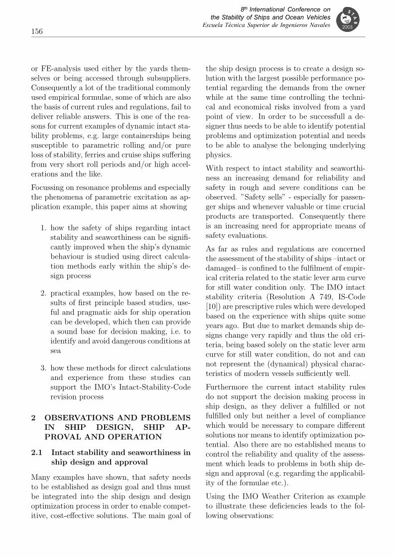
Fig. 7 shows some interesting results for shipsthat tend to suffer from pure loss failures due tolow stability on the wave crest. Here the ideawas that there might be a connection betweenthe alteration of the maximum righting leverbetween wave trough and wave crest conditionand the capsizing probabilities. And the generaltrend shows clearly that the capsizing probabil-ity increases with higher maximum lever alter-ations, which suggests that the stability valuesfor GZmax to be attained in calm water shouldsomehow depend on their alterations in waves.
0.00
0.4
0.05 0.10 0.15 0.20 0.25Alt
erat
ion
of m
ax. l
ever
wav
e cr
est −
wav
e tr
ough
0.300.3
0.5
0.6
0.7
0.8
0.9
1.0
Capsizing probability, sample region North Atlantic
Figure 7: Capsizing probabilities versus alter-ations of the maximum righting lever betweenwave crest and wave trough condition for vesselssuffering from pure loss of stability
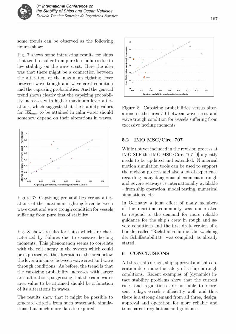
Fig. 8 shows results for ships which are char-acterized by failures due to excessive heelingmoments. This phenomenon seems to correlatewith the roll energy in the system which couldbe expressed via the alteration of the area belowthe leverarm curve between wave crest and wavethrough conditions. As before, the trend is thatthe capsizing probability increases with largerarea alterations, suggesting that the calm waterarea value to be attained should be a functionof its alterations in waves.
The results show that it might be possible togenerate criteria from such systematic simula-tions, but much more data is required.
0.7
0.6
0.5
0.4
0.3
0.2
0.10.00
Capsizing probability, sample region North Atlantic
0.02 0.04 0.06 0.08 0.10 0.12 0.14 0.16
(conv.)
Are
a 50
alt
erat
ion
wav
e tr
ough
− w
ave
cres
t
Figure 8: Capsizing probabilities versus alter-ations of the area 50 between wave crest andwave trough condition for vessels suffering fromexcessive heeling moments
5.2 IMO MSC/Circ. 707
While not yet included in the revision process atIMO-SLF the IMO MSC/Circ. 707 [9] urgentlyneeds to be updated and extended. Numericalmotion simulation tools can be used to supportthe revision process and also a lot of experienceregarding many dangerous phenomena in roughand severe seaways is internationally available– from ship operation, model testing, numericalsimulations, etc.
In Germany a joint effort of many membersof the maritime community was undertakento respond to the demand for more reliableguidance for the ship’s crew in rough and se-vere conditions and the first draft version of abooklet called ”Richtlinien fur die Uberwachungder Schiffsstabilitat” was compiled, as alreadystated.
6 CONCLUSIONS
All three ship design, ship approval and ship op-eration determine the safety of a ship in roughconditions. Recent examples of (dynamic) in-tact stability problems show that the currentrules and regulations are not able to repre-sent todays vessels sufficiently well, and thusthere is a strong demand from all three, design,approval and operation for more reliable andtransparent regulations and guidance.

168
In this paper some examples are given on hownumerical motion simulations and appropriateevaluation methodologies can support the de-sign of safer ships and provide a basis for thecompilation of ship specific guidance. Furtherexamples show how these developments can alsobe used as a basis for rule development and thecompilation of general ”guidance to the master”applicable to all ships. Further developmentsare targeted in the ongoing research projectSinSee in order to allow for quantitative safetyassessments of a ships intact stability in the fu-ture.
At IMO-SLF the revision process of the IS-Codeis ongoing and all three ship design, approvaland operation will clearly benefit from the in-tended change towards transparent, perfomancebased criteria – as will the ship’s safety with re-spect to intact stability as such. And also theIMO MSC/circ. 707 needs to be included in therevision process, in order to provide more ap-propriate guidance for ship operation.
7 ACKNOWLEDGEMENTS
The authors are indebted to the German Min-istry of Education, Research, and Technology,BMBF, for funding the projects Roll-S andSinSee.
References
[1] V. L. Belenky. Probalistic approach for in-tact stability standards. SNAME transac-tions, Vol. 108, 2000, pages 123–146, 2000.
[2] Tobias Blome and Stefan Kruger. Stabilityin quartering Waves – a critical Review oftoday’s Stability Code. In A. Papaniko-laou, editor, Proceedings IMDC 2003,Athens, 2003.
[3] P. Blume. Development of new stabilitycriteria for modern dry cargo vessels. Inn.n, editor, PRADS – Practical Design ofShips and Marine Units, Trondheim, 1987.Elsevier.
[4] H. Cramer and S. Kruger. Numericalcapsizing simulations and consequences forship design. STG summer meeting, 2001.
[5] H. Cramer and J. Tellkamp. Towardssafety as a performance criteria in ship de-sign. In The Royal Institution of Naval Ar-chitects, editor, Passenger Ship Safety, In-ternational Conference, London, 2003.
[6] W. N. France, M. Levadou, T. W. Treakle,J. R. Paulling, K. Michel, and C. Moore.An investigation of head-sea parametricrolling and its influence on container lash-ing systems. Marine Technology, Vol. 40,(1):1–19, 2003.
[7] A. Francescutto and A. Serra. A crit-ical analysis of weather criterion for in-tact stability of large passenger vessels. InA. Francescutto, editor, 5th internationalworkshop Stability and operational safety ofships, Trieste, 2001.
[8] A. Francescutto and A. Serra. Experimen-tal tests on ships with large values of B/T,OG/T and roll period. In S. Grochowal-ski, editor, 6th International Ship StabilityWorkshop, New York, 2002.
[9] International Maritime Organization IMO.Guidance to the master for avoiding dan-gerous situations in following and quater-ing seas. MSC/Circ. 707, IMO, 1995.
[10] International Maritime Organization IMO.Code on Intact Stability for all types ofships covered by IMO instruments. Reso-lution A.749(18) as amended by resolutionMSC.75(69), IMO, 2002.
[11] K. McTaggart and J. O. deKat. Cap-size risk of intact frigates in irregularseas. SNAME transactions, Vol. 108, 2000,pages 147–177, 2000.
[12] Germany SLF45. Proposals with regardto the scope of revising the IS Code andthe related MSC/circ. 707. Document SLF45/6/2, IMO – SLF Sub–Committee, 2002.

169
[13] Germany SLF45. Remarks concerning theWeather Criterion. Document SLF 45/6/3,IMO – SLF Sub–Committee, 2002.
[14] Italy SLF45. Weather criterion for largepassenger ships. Document SLF 45/6/5,
IMO – SLF Sub–Committee, 2002.
[15] H. Soding. Ermittlung der Kentergefahraus Bewegungssimulationen. SchiffstechnikBd. 34, pages 28–39, 1987.