
WORKING DRAFT - Far North District
410
WORKING DRAFT ENGINEERING STANDARDS 2021 Issue 0.3 – May 2021
Transcript of WORKING DRAFT - Far North District

WORKING DRAFT
ENGINEERING STANDARDS 2021
Issue 0.3 – May 2021
Far North District Council Engineering Standards
Document Control
Version Comments Author Date Finalised Approved by Date Approved Date Published
0.1 For internal FNDC Working Group Review FNDC Dec 2020 FNDC In Progress In Progress
0.2 For Practitioners, Northland Reginal Council, Far North Waters, Northland Transport Alliance, FNDC internal, Disability Action Group Review (Working Draft)
FNDC Feb 2021 FNDC In Progress In Progress
0.3 For Public Consultation (Working Draft) FNDC May 2021 FNDC In Progress In Progress
Document Revision
The Far North District Councils Engineering Standards shall be reviewed to align with the District Plan. If you identify any issues with this document, or any areas where improvements can be made, please contract Councils Engineering Team Leader – Infrastructure and Asset Management Department.

Far North District Council Engineering Standards
1
The ES 2021 has been significantly updated since the 2009 version. This 2021 version has been developed from the Whangarei District Council Engineering Standards together with other changes incorporating input from Council staff and practitioners.
Council acknowledges input into the ES from the following:
Hamilton City Council,
Whangarei District Council,
Kaipara District Council,
New Zealand Transport Agency,
The New Zealand Fire Service,
Historic Places Trust, and
Network Utility Operators.

Far North District Council Engineering Standards
2
CHAPTER 1: GENERAL ........................................................................................................................ 1
1.1. Introduction .................................................................................................................... 4
1.2. Statutory Requirements ................................................................................................. 6
1.3. Abbreviations and Definitions ........................................................................................ 7
1.4. General Engineering Requirements .............................................................................. 14
1.5. Design ........................................................................................................................... 16
1.6. Construction Process .................................................................................................... 33
1.7. Completion of Works .................................................................................................... 40
CHAPTER 2: SITE DEVELOPMENT SUITABILITY (GEOTECHNICAL AND NATURAL HAZARDS) ........... 47
2.1. Introduction .................................................................................................................. 49
2.2. Consents and Approvals ............................................................................................... 50
2.3. Geotechnical/ Hazard Assessment ............................................................................... 54
2.4. Geotechnical Design ..................................................................................................... 61
2.5. Construction ................................................................................................................. 64
2.6. Completion of Works .................................................................................................... 65
CHAPTER 3: TRANSPORTATION ....................................................................................................... 66
3.1. Introduction .................................................................................................................. 69
3.2. Design ........................................................................................................................... 74
3.3. Construction ............................................................................................................... 105
3.4. Completion of Works .................................................................................................. 116
CHAPTER 4: STORMWATER AND DRAINAGE ................................................................................. 117
4.1. Introduction ................................................................................................................ 120
4.2. Receiving Environment Requirements ....................................................................... 124
4.3. Design ......................................................................................................................... 128
4.4. Construction ............................................................................................................... 172
4.5. Completion of Works .................................................................................................. 184
CHAPTER 5: WASTEWATER ............................................................................................................ 186

Far North District Council Engineering Standards
3
5.1. Introduction ................................................................................................................ 189
5.2. Design ......................................................................................................................... 195
5.3. Construction ............................................................................................................... 228
5.4. Completion of Works .................................................................................................. 239
CHAPTER 6: WATER SUPPLY AND RETICULATION ......................................................................... 242
6.1. Introduction ................................................................................................................ 245
6.2. Design ......................................................................................................................... 248
6.3. Construction ............................................................................................................... 268
6.4. Completion of Works .................................................................................................. 275
CHAPTER 7: PUBLIC SPACES AND LANDSCAPE DEVELOPMENT WORKS ....................................... 277
7.1. Introduction ................................................................................................................ 280
7.2. Design ......................................................................................................................... 283
7.3. Construction ............................................................................................................... 300
7.4. Completion of Works .................................................................................................. 309
CHAPTER 8: ELECTRICITY, TELECOMMUNICATIONS AND GAS ...................................................... 313
8.1. Introduction ................................................................................................................ 315
8.2. Design ......................................................................................................................... 316
8.3. Construction ............................................................................................................... 318
8.4. Completion of Works .................................................................................................. 319
APPENDICES ....................................................................................................................................... 320
Appendix A Design for Surge and Fatigue ............................................................................... 322
Appendix B ES-SEW1 ................................................................................................................ 327
Appendix C ES – PS1 ................................................................................................................ 333
Appendix D ES – PS4 ................................................................................................................ 335
Appendix E ES-PO1 .................................................................................................................. 337
Appendix F Permeability Test Sheets ...................................................................................... 340
Appendix G Drawing Standards ............................................................................................... 343

Far North District Council Engineering Standards
4
Appendix H Example As-Built Drawings .................................................................................. 347
Appendix I Asset Attributes ..................................................................................................... 357
Appendix J Checklist for Supporting Information .................................................................... 374
Appendix K List 1. Reserve Playgrounds - Approved Playground Equipment and Surfacing Suppliers and Installers ............................................................................................................ 380
Appendix L List 2. Reserves and Streetscapes - Approved Common Landscape Furniture Products and Suppliers. ........................................................................................................... 381
Appendix M List 3. Reserves and Streetscapes - Suitable Shrub and Plant Species for Reserve and Streetscape Planting ......................................................................................................... 389
Appendix N List 4. Reserves and Streetscapes - Suitable Tree Species for Reserve and Streetscape Planting. ............................................................................................................... 390
Appendix O Spreadsheet 1. Public Toilets – Gold and Silver Standards for New Public Conveniences ........................................................................................................................... 391
DRAWING SHEETS .............................................................................................................................. 392
Sheet 1 Standard Symbols ....................................................................................................... 396
Sheet 2 Urban Road and Service Lane Details ......................................................................... 397
Sheet 3 Rural Road Details....................................................................................................... 398
Sheet 4 Traffic Sightlines for Vehicles Entrances ..................................................................... 399
Sheet 5 Scala Penetrometer Chart .......................................................................................... 400
Sheet 5A Equivalent Subgrade CBR Design Chart .................................................................... 401
Sheet 6 Design Chart for Flexible Pavements .......................................................................... 402
Sheet 7 Urban Privateway Details ........................................................................................... 403
Sheet 8 Urban Privateway Details - Notes ............................................................................... 404
Sheet 9 Rural Privateway Details ............................................................................................. 405
Sheet 10 Rural Privateway Details - Notes .............................................................................. 406
Sheet 11 Cul De Sac Details ..................................................................................................... 407
Sheet 12 Footpath and Stormwater Kerb Connection Details ................................................ 408
Sheet 13 Kerb & Channel Details ............................................................................................. 409
Sheet 14 Typical Drainage Subsoil Details ............................................................................... 410
Sheet 15 Standard Road Swale Details .................................................................................... 411
Sheet 16 Standard Road Swale Details .................................................................................... 412
Sheet 17 Accessible Crossing Details ....................................................................................... 413
Sheet 18 Vehicle Crossing - Residential ................................................................................... 414
Far North District Council Engineering Standards
5
Sheet 19 Vehicle Crossing - Commercial/ Industrial ................................................................ 415
Sheet 20 Alternative Vehicle Crossing ..................................................................................... 416
Sheet 21 Vehicle Crossing - Rural ............................................................................................ 417
Sheet 22 Vehicle Crossing Notes ............................................................................................. 418
Sheet 23 Vehicle Crossing - Maximum Graded Profiles for Urban/ Rural Properties ............. 419
Sheet 24 Street Sign for Public Roads ...................................................................................... 420
Sheet 25 Street Sign for Private Roads .................................................................................... 421
Sheet 26 Vehicle Tracking Curves ............................................................................................ 422
Sheet 27 Heavy Goods Vehicle Tracking Curves ...................................................................... 423
Sheet 28 Heavy Goods Vehicle Tracking Curves ...................................................................... 424
Sheet 29 Layout of Services ..................................................................................................... 425
Sheet 30 Minimum Clearance Between Services .................................................................... 426
Sheet 31 Pipe Bedding and Backfill.......................................................................................... 427
Sheet 32 Pipe Protection and Bulkhead Details ...................................................................... 428
Sheet 33 PE Pipe Connections to Manhole ............................................................................. 429
Sheet 34 Catch-Pit Details ....................................................................................................... 430
Sheet 35 Inlet and Outlet Structures ....................................................................................... 431
Sheet 36 Stormwater Secondary Flow Path Treatment .......................................................... 432
Sheet 37 Stormwater and Sewer Connections ........................................................................ 433
Sheet 38 Private Connections .................................................................................................. 434
Sheet 39 Standard Precast Manhole ....................................................................................... 435
Sheet 40 Standard Precast Manhole - Step Rung .................................................................... 436
Sheet 41 Wastewater Pumping Station - Site Layout and Plan ............................................... 437
Sheet 42 Sewer Pump Station Typical Details (1) .................................................................... 438
Sheet 43 Sewer Pump Station Typical Details (2) .................................................................... 439
Sheet 44 RPZ Water Connection.............................................................................................. 440
Sheet 45 Water Pipeline Details .............................................................................................. 441
Sheet 46 Single Meter Box Connection ................................................................................... 442
Sheet 47 Multiple Water Connections .................................................................................... 443
Sheet 48 Valve and Hydrant Markers ...................................................................................... 444

Far North District Council Engineering Standards
6
Sheet 49 Anchor Block and Valve Installation Details ............................................................. 445
Sheet 50 Anchor Block Details ................................................................................................. 446
Sheet 51 Air Valve Details ........................................................................................................ 447
Sheet 52 Magflow & Flow Control Valve Installation .............................................................. 448
Sheet 53 Water Supply Pump Station Details.......................................................................... 449
Sheet 54 Fence Types .............................................................................................................. 450
Sheet 55 Street Tree Planting Within Recessed Parking Bay .................................................. 451
Sheet 56 Street Tree Planting Clearances ............................................................................... 452
Sheet 57 Tree Planting Detail .................................................................................................. 453
Sheet 58 Removable Bollard Detail ......................................................................................... 454
Sheet 59 Specification/Details – Reserve Paths – Widths, Gradients, and Fall Heights .......... 455
Sheet 60 Specification/Details – Reserve Paths – Material Specifications and Concrete Cutting 456
Sheet 61 Specification/Details – Reserve Paths – Connections to Accessible Carparking and Amenities ................................................................................................................................. 457
Sheet 62 Specification/Details – Reserve Paths – Paths and Vehicle Accesses in to Reserves 458
Sheet 63 Specification/Details – Reserve Paths – Threshold Design and Vehicle Barriers ..... 459
Sheet 64 Specification/Details – Reserve Fencing - Standard Reserve Fencing Designs ......... 460
Sheet 65 Specification/Details – Reserve Playgrounds - Safety Surfacing and Edging Details for Accessible Playgrounds ............................................................................................................ 461
Sheet 66 Specifications/Details – Streetscapes - Planting for Water Sensitive Design in the Streetscape. ............................................................................................................................. 462
Sheet 67 Specifications/Details – Streetscapes - Tree Pits and Tree Planting within the Road Corridor. ................................................................................................................................... 463
Sheet 68 Specification/Details – Streetscapes – Service Free Berm for Landscaping Purposes, and Utility Placement. ............................................................................................................. 464
Sheet 69 Specification/Details – Streetscapes – Street Tree Planting Clearances .................. 465
Sheet 70 Specifications/Details – Reserves and Streetscapes -Tree Planting Methodology and Landscape Planting Area Preparation. .................................................................................... 466
Sheet 71 Specifications/Details – Reserves and Streetscapes - Landscape Bedding Profiles and Preparations. ........................................................................................................................... 467

Far North District Council Engineering Standards Chapter 1: General
1
Chapter 1: General

Far North District Council Engineering Standards Chapter 1: General
2
1.1. INTRODUCTION ............................................................................................................................ 4
1.1.1. The Engineering Standards ............................................................................................. 4
1.1.2. Scope ............................................................................................................................... 4
1.1.3. Overview ......................................................................................................................... 4
1.1.4. Reference Documents .................................................................................................... 5
1.2. STATUTORY REQUIREMENTS ....................................................................................................... 6
1.2.1. General............................................................................................................................ 6
1.2.2. Relationship with the District Plan ................................................................................. 7
1.3. ABBREVIATIONS AND DEFINITIONS ............................................................................................. 7
1.4. GENERAL ENGINEERING REQUIREMENTS ................................................................................. 14
1.4.2. Developer's Representative .......................................................................................... 14
1.4.3. Cost of the Work and District Council Contributions.................................................... 15
1.4.4. Insurance ...................................................................................................................... 15
1.4.5. Quality Assurance and Quality Control ......................................................................... 16
1.5. DESIGN ....................................................................................................................................... 16
1.5.1. General.......................................................................................................................... 16
1.5.2. Information Requirements - Resource Consent Applications ...................................... 20
1.5.3. Detailed Design/Approval ............................................................................................. 22
1.6. CONSTRUCTION PROCESS .......................................................................................................... 33
1.6.1. General.......................................................................................................................... 33
1.6.2. Construction Management Plan ................................................................................... 33
1.6.3. Inspection and Testing Plan (ITP) .................................................................................. 34
1.6.4. Pre – Construction Meeting .......................................................................................... 34
1.6.5. Site Works, Site Inspections and Approvals .................................................................. 35
1.6.6. Construction within Road Corridor ............................................................................... 40

Far North District Council Engineering Standards Chapter 1: General
3
1.7. COMPLETION OF WORKS ........................................................................................................... 40
1.7.1. General.......................................................................................................................... 41
1.7.2. As-Built Plans, Asset Information Schedules, Operation and Maintenance Manuals .. 41
1.7.3. Contractual Matters ...................................................................................................... 44

Far North District Council Engineering Standards Chapter 1: General
4
1.1. Introduction
1.1.1. The Engineering Standards
The Far North District Council (FNDC) Engineering Standards (ES) sets out the processes and standards that are expected to be followed and met whenever any development project or Engineering work is undertaken within the District. The ES recognises that the District Council and other network operators will become the owners and operators of roads and other infrastructure, which are created and vested in the land development process.
It is important that the District Council and the community has confidence that the infrastructure and associated systems are competently designed and constructed in a manner which ensures that they are fit for purpose and can be expected to last well into the future.
The ES is the District Council’s minimum acceptable technical specification.
1.1.2. Scope
Any infrastructure design or construction within the Far North District :
The District Council's capital and/or operational works contracts or professional services agreements,
Development works regardless of whether the infrastructure will be vested in the District Council or remain in private ownership, or
Any other form of infrastructure development that will connect to the District Council’s existing infrastructure network,
shall use the ES as the means of designing, constructing, testing and signing off the works.
If, for any reason, the ES requirements cannot be meet or a design or method of construction outside the ES is more desirable, an Alternative Design (1.5.1.2 Alternative Designs) can be proposed.
The District Council acknowledges that the development of some infrastructure is not covered by the specific requirements in the ES.
Examples of such infrastructure are:
Water reservoirs,
Bulk water mains,
Trunk sewers,
Structures, and
Traffic signals
These works shall be undertaken on a Specific Design basis involving the District Council’s engineers and asset managers, relevant codes and standards and in accordance with accepted industry practice.
1.1.3. Overview
This section:

Far North District Council Engineering Standards Chapter 1: General
5
Introduces the philosophy and scope of the ES,
Provides referencing and definitions for the ES,
Identifies statutory requirements,
Describes the engineering design approval process, and
Provides generic guidance across all infrastructure groups for:
i. As-Built Plans,
ii. Working in the Transport Corridor,
iii. Temporary traffic management, and
iv. General forms and checklists for developments.
1.1.4. Reference Documents
The following documents are referenced in this Chapter;
1.1.4.1 Statutory
Building Act 2004
Government Roading Powers Act 1989
Local Government Act 1974
New Zealand Building Code
Northland Regional Council Regional Plan
District Plan and Operative District Plan
Public Works Act 1981
Resource Management Act 1991
1.1.4.2 New Zealand Standards
NZS 4121: 2001 Design for Access and Mobility, Buildings and Associated Abilities
NZS 1100 Series - Technical drawing
NZS 3604:2011 - Timber-framed buildings
NZS 4229:2013 - Concrete masonry buildings not requiring specific engineering design
NZS 4402.1 to 7 Series - Methods of testing soils for civil engineering purposes
SNZ PAS 4509:2008 - New Zealand Fire Service firefighting water supplies code of practice
1.1.4.3 District Council Documents
To be confirmed
1.1.4.4 Other Referenced Documents
ENZ Practice Note 01: Guidelines on Producer Statements - January 2014
ENZ Practice Note 02: Peer Review - Reviewing the work of another Engineer - 2018

Far North District Council Engineering Standards Chapter 1: General
6
NZ Utilities Advisory Group: National Code of Practice for Utility Operators' Access to Transport Corridors 2015.
NZTA Code of Practice for Temporary Traffic Management
Water New Zealand; Pipe Inspection Manual 2006
1.2. Statutory Requirements
1.2.1. General
The Developer is responsible for obtaining all necessary consents, providing for the protection of other property from damage resulting from the development and complying with all statutes, regulations, by-laws, national, district and regional planning documents and subsequent revisions and updates at the time of consent application, including, but not limited to:
• Building Act 2004 and amendments
• Ministry of Business, Innovation and Employment (MBIE)
• Electricity Act 1992 and amendments
• Health and Safety at Work Act 2015
• Electricity Act 1992 and amendments
• Fencing Act 1978
• Land Transfer Act 1952 and amendments
• Land Transport Management Act 2003 and amendments
• Local Government Act 1974 and amendments
• Health (Drinking Water) Amendment Act 2007
• Local Government Act 2002 and amendments
• Plumbers, Gasfitters and Drainlayers Act 1976 and amendments
• Plumbers, Gasfitters and Drainlayers Act 2005 and amendments
• Public Works Act 1981 and amendments
• Resource Management Act 1991 and amendments
• Telecommunications Act 2001 and amendments
• Government Roading Powers Act 1989 and amendments
• Transport Management Act 2003 and amendments
• Water Supplies Protection Regulations 1961 and amendments
• Reserves Act 1997 and amendments

Far North District Council Engineering Standards Chapter 1: General
7
• Regional Plan for Northland
• Regional Coastal Plan for Northland
• NZ Coastal Policy Statement
• FNDC Operative District Plan
• FNDC Control of earthworks Bylaw 2019
• FNDC The Control of On-site Wastewater Disposal Systems Bylaw 2010
• FNDC The Control of Vehicle Crossings Bylaw 2010
1.2.2. Relationship with the District Plan
Where resource consent is required under the District Plan compliance with the ES will be specified in consent conditions that require infrastructure or other such engineering works.
1.3. Abbreviations and Definitions
In the ES, the following abbreviations have been used;
AADT Annual average daily traffic
ADWF Average Dry Weather Flow (l/s)
AEP Annual Exceedance Probability (refer to definitions below)
ARI Average Return Interval
CAR Corridor Access Request
CDP Catchment Drainage Plan
CMP Catchment Management Plan
DN Nominal Diameter
ES Engineering Standards (this document)
HIRDS High Intensity Rainfall Design System in the form of software produced by NIWA
ISO International Standards Organisation
NRC Northland Regional Council
NZBC New Zealand Building Code
NZS New Zealand Standard, as published by the Standards New Zealand (SNZ)
NZTA New Zealand Transport Agency (Previously LTSA and LTNZ)
OD Outside diameter
PDWF Peak Dry Weather Flow (l/s)
PE 100 Polyethylene type 100

Far North District Council Engineering Standards Chapter 1: General
8
PE 80B Polyethylene type 80B
PN Pressure nominal
PPM Parts per Million
RMA Resource Management Act
RTS Road and Traffic Standards (Published by the LTSA)
SCADA Supervisory, Control and Data Acquisition
SN Stiffness number
TMP Traffic Management Plan
TSS Total Suspended Solids
vpd Vehicles per day
FNDC Far North District Council
AADT Annual average daily traffic
ADWF Average Dry Weather Flow (l/s)
AEP Annual Exceedance Probability
ARI Average Return Interval
CAR Corridor Access Request
CDP Catchment Drainage Plan
CMP Catchment Management Plan
WAP Work Access Permit
In the ES, unless inconsistent with the context, the following definitions shall apply.
Access (Low Volume) Refer to Access (Road) below and Table 3-2.
Access (Road) Roads not classified as arterial or collector, whose major function is to provide access to properties rather than provide routes for other traffic. See Table 3-2.
Annual Exceedance Probability (AEP)
The probability of exceedance of an event (generally a rainfall storm) within a period of one year. (1% AEP is equivalent to 1 in 100-year storm)
Approved District Council approval in writing
Certified Drainlayer Work on or connections to live sewers shall be carried out by Certified Drainlayers. The list is available on the District Councils website (see also Licensed Drainlayer)
The District Council reserves the right to require that work relating to trunk sewers, or other critical assets be carried out by its Sewer Reticulation Maintenance Contractor.

Far North District Council Engineering Standards Chapter 1: General
9
Arterial Road Major roads with high traffic volumes or a significant component of through traffic. These include major roads into and through the District, and roads serving significant areas of development
Attenuate/Attenuation To lessen the intensity/severity/effects of an activity to a defined reduction, generally no more than pre-development levels
Average Return Interval (ARI)
The average, or expected, value of the periods between exceedances of a given rainfall total accumulated over a given duration. Refer to Annual Exceedance Probability above.
Catchment/Catchment Area
The area over which surface water run-off will tend to flow under gravity towards a common outlet point
Carriageway Width The road width normally traversed or occupied by vehicles. See Sheet 2
Collector Road Roads that collect traffic from specific areas or link important roads or major traffic generators.
Commercial and Industrial Area
Land contained within Mixed Use, Light Industrial, Heavy Industrial Zones However, other areas may be added by changes to the District Plan. (Council should be consulted beforehand to determine the standard that will be applied to a particular area if there is any doubt)
Community Sewerage System
A wastewater reticulation, treatment and disposal system, that serves two or more properties and/or units, dwellings and houses. This applies irrespective of whether or not it is maintained by the District Council. The community sewerage system is to comply with Building Act 2004
Consent Holder See Developer
Contractor The company engaged to undertake the physical works
District Council Far North District Council
Curve Number (CN) An empirical parameter used in hydrology for predicting direct runoff or infiltration from rainfall excess. The run-off curve number is based on the area's hydrologic soil group, land use, surface treatment, gradient and hydrologic condition
Cycleway The part of a road that is laid-out or constructed primarily for cyclists. It may include the associated edging, kerb and channel
Defects Liability Period The period required by the District Council, after the completion of the works, for which the Developer is responsible for repairing defects that may arise during this period, due to faulty materials and/or workmanship. The District Council will normally require a bond to cover any necessary works. See Section 1.7.3.1 Defects Liability Period.
Design/Technical Review A review of a specific part of an overall design or report by a suitably qualified and experienced professional. Refer to document ENZ Practice Note 01: Guidelines on Producer Statements - January 2014 on the Engineering New Zealand (previously IPENZ) website. The review can be done internally with the District Council or externally. https://www.engineeringnz.org/resources/practice-notes-and-guidelines/

Far North District Council Engineering Standards Chapter 1: General
10
Also see Peer Review
Developer In relation to resource consents, is the applicant, owner, Trust, Company, person(s), or organisation or legal entity who have been granted consent to undertake the activities applied for.
Developer’s Representative
See Section 1.4.1 Developer's Representative
District Plan The operative and proposed plans for the District and any combination of them applicable to resource consent applications
Drain A pipe or channel that conveys sewage or stormwater flow. Drainage has a corresponding meaning
Earthworks means the alteration or disturbance of land, including by moving, removing, placing, blading, cutting, contouring, filling or excavation of earth (or any matter constituting the land including soil, clay, sand and rock); but excludes gardening, cultivation, and disturbance of land for the installation of fence posts.
Footpath The part of a road that is laid out or constructed primarily for pedestrians. It may not include the associated edging and kerb
Geo-Professional A chartered professional engineer (CPEng) or an engineering geologist, with recognised qualifications and experience in geotechnical engineering, and experience related to land development
Good Ground Is defined in NZS 3604:2011, and in NZS 4229:2013:
as ‘any rock or soil capable of withstanding an ultimate bearing capacity of 300kPa (i.e. an allowable bearing pressure of 100kPa using a factor of safety of 3), but excludes:
Potentially compressible ground such as topsoil, soft soils such as clay which can be moulded easily in the fingers, and uncompacted loose gravel which contains obvious voids
Expansive soils being those that have a liquid limit of more than 50% when tested in accordance with NZS 4402 Test 2.2 and a linear shrinkage of more than 15% when tested from the liquid limit in accordance with NZS 4402 Test 2.6, and
Any ground which could foreseeably experience movement of 25mm or greater for any one or a combination of land instability, ground creep, subsidence, seasonal shrinking and swelling, frost heave, changing ground water level, erosion, dissolution of soil in water, and effects of tree roots’
Gradient The slope of a surface or object off horizontal generally described either as a percentage or as a ratio i.e. 1:4 is equivalent to 25% or 250mm/m
Ground The surface of the earth and below, whether soil or rock
Heavy Vehicle Any vehicle exceeding 3500kg gross laden weight
Household Unit (hu) Means a building(s) or part of a building that is used for a residential activity exclusively by one household, and must include sleeping, cooking, bathing and toilet facilities.

Far North District Council Engineering Standards Chapter 1: General
11
Household Unit
Equivalent (HUE)
The volume of effluent discharged from an average Household Unit in a 24-hour period This is also used to determine equivalent flows from various commercial activities.
Hydraulic The static and dynamic behaviour of fluids
Hydrology The study of the movement, distribution, and quality of water.
Independently Qualified Person (IQP)
A specialist, approved under the District Council’s Resource Consent IQP process (not under the Building Act 2004), having the appropriate skills and qualifications to carry out specific procedures, and who has no financial interest in the proposal/project. See Section 1.5.1.3 The Role of the IQP & Table 1-1 of the ES.
Invert The bottom of a pipe, channel or cesspit
Legal Width for Roads (road reserve)
For public roads, the width of the strip of land that has been declared road in accordance with Section 114 of the Public Works Act 1981
For private roads, private ways or easements (rights-of-way), the width of the strip of land over which the public, shared owners or landowners with dominant tenement are legally entitled to pass without the specific approval of any one landowner.
Licensed Contractor A specialist contractor who has been Licensed by the District Council to construct or modify new water reticulation (including reticulation that will be vested to the District Council) and carry out work on live mains, make connections to live mains, install a water meter or carry out shut downs of live water reticulation.
Licensed Drainlayer Licensed Drainlayers are permitted to construct or modify new works that will be vested to the District Council. They may not carry out work on live sewers, make a connection to live sewers or carry out shutdowns of live sewer.
Refer to the District Councils website for further information (see also Certified Drainlayer)
Manhole A chamber which provides access from the surface to an underground service
Means of Compliance A method by which the requirements of the standard may be complied with
Modified Rational Method
This method provides a way to calculate the hydrograph from a catchment based on rational method C values and the peak intensity. There is no ‘loss method’ associated with the Modified Rational Method. The underlying assumption is that the peak intensity is maintained for a long enough duration to reach peak flow at the outlet of the catchment
Network Utility Operator
Has the same meaning as given to it by Section 166 of the Resource Management Act 1991
Outlet The discharge point of a gravity or pumped fluid system
Overland Flow Path The path taken by run-off. This may be either primary or secondary flows

Far North District Council Engineering Standards Chapter 1: General
12
Owner Includes an owner of land, whether beneficially or as trustee, and their agent or attorney, and a mortgagee acting in exercise of power of sale. It also includes the Crown, the Public Trustee, and any person, local authority, board or other body or authority however designated, constituted or appointed, having power to dispose of the land or interest therein by way of sale
Pavement The layer(s) of a road or access structure above the subgrade, incorporating sub-base and/or basecourse crushed granular material whether chemically stabilised or not, or rigid material (such as concrete), but excluding any seal coat. See Sheet 2 and Sheet 3
Peak Flow (Q) m³/s Determined from the formula Q = CIA/360, where Q = discharge, C = run-off coefficient, I = rainfall intensity (mm/hr.), A = drainage area (Ha)
Peer Review An overall review of a design or report by a suitably qual ified and experienced professional. Refer to https://www.engineeringnz.org/resources/practice-notes-and-guidelines/
Also see Design/Technical Review
Primary Design Flow The estimated stormwater run-off selected to provide a reasonable degree of protection to surrounding land and buildings. This flow will generally be piped or contained within narrow confines and may be under public control by reserve or easement
Principal Water Mains All water reticulation 100mm inside diameter or greater, including associated valves
Private Road Any roadway, place or arcade laid out within the District on private land intended for the use of the public
Private Way/Private Accessway
A road or passage over private land that is not open or intended to be open to general public use. Also see District Plan definitions
Registered Contractor A specialist contractor who has been approved by the District Council to construct or modify new water reticulation (including reticulation that will be vested to the District Council). They MAY NOT carry out work on live mains, make connections to live mains, install a water meter or carry out shutdowns of live water reticulation.
See the District Council’s website for a list of Registered Contractors (see also Licensed Contractor)
Regulatory Review As defined in ENZ Practice Note 02: Peer Review - June 2003
Rider Main Water reticulation less than 100mm inside diameter, including associated valves, that serves more than one property
Rising Main Pressure reticulation between a pumping station and a non pressurised junction or termination, including another pumping station, manhole, reservoir or treatment system
Road or Street Road means, subject to Sections 43(1), 51(1), 54(1) & 55 of the Government Roading Powers Act 1989, any road as defined in Section

Far North District Council Engineering Standards Chapter 1: General
13
315(1) of the Local Government Act 1974/2002, and roading has a corresponding meaning
Run-off Coefficient (C) Used to estimate the amount of rainfall run-off that will occur off any given surface. See Table 4-4. TP108???
Rural Area The following rural Environments as defined in proposed Rural Production, Rural Settlement, Rural Residential and Horticulture Zones
Where a Resource Consent allows reduced lot sizes within these Environments, the District Council may require certain or all ‘Urban’ standards to be applied.
Secondary Flow Path The path taken by run-off in excess of the primary design flow, which has the purpose of preventing inundation of surrounding building sites. When calculating secondary flow path dimensions, blockage or failure of the primary system shall be considered
Service Lane Has the meaning given in Section 315 of the Local Government Act 1974/2002
Sewer An enclosed pipe not less than 100mm inside diameter used for conveying sewage by gravity
And enclosed pipe not less than 40mm inside diameter used for conveying sewage by pressure sewer system
Specific Design A design that requires calculation, either using a method referenced in the ES, or outside of the scope of methods used in the ES.
Specific Designs shall be prepared by a suitably qualified person with adequate expertise and experience in accordance with sound and accepted engineering practice and principles and shall meet the objectives set out in the ES and/or the District Plan. The design shall comply with New Zealand Standard specifications and/or other nationally recognised procedures and systems
Standard Design Vehicle
See Sheet 26 for details
Stable Ground Land that in the opinion of a suitably qualified and experienced Geo-Professional is in a state which is unlikely to settle, slip, erode or otherwise move, allowing for a suitable factor of safety to the detriment of superimposed buildings, services, roads or property
Stormwater Rainwater that flows via overland flow, channels or pipes
Stormwater Attenuation/ Treatment Pond
A permanent pond, wetland or dry detention basin, designed to attenuate peak stormwater flows and provide water quality treatment
Sub-base The material between the subgrade and basecourse aggregate
Subgrade The top 1m layer of the road formation below the pavement. It includes any stabilisation, granular or non-granular material of a lower standard than quarry run aggregate

Far North District Council Engineering Standards Chapter 1: General
14
Surcharge A pipe running in excess of its gravity flow condition, above full and under a degree of pressure
Survey Plan As described in Section 2 of the Resource Management Act 1991.
Swale Drain A grassed surfaced channel for conveying stormwater generally at low, non-eroding velocities to provide water quality improvements.
Transport Corridor For the purpose of the ES, includes all Road or Street as defined above and includes all land from boundary to boundary (including the Berm and Carriageway).
Urban Area Land contained within the following District Plan Environments: Residential, Rural Settlement and Mixed-Use Zones
1.4. General Engineering Requirements
The District Council will undertake a review of a development application prior to issue of a resource consent, in order to establish suitable engineering consent conditions.
Typically, Engineering Approval consists of three phases:
Post-consent engineering design approval (pre-construction),
Works commencement, inspection and testing (during construction), and
Works completion and acceptance (post-construction).
The following sections detail the expectations of the District Council and the information submission requirements for Engineering Approval
For land use developments, Engineering Approval is required unless specified otherwise in conditions of consent.
1.4.1. Developer's Representative
The Developer shall nominate a specialist representative to liaise with the District Council, who should be a licensed cadastral surveyor, resource management/planning consultant, or chartered professional engineer, suitably experienced in all phases of resource consent, and available for site visits within 24 hours of being so requested by the District Council. A suitably qualified and experienced person in a related field may be nominated subject to acceptance by the District Council.
The District Council will generally not allow the Developer to act in this position unless they can provide proof that they have the necessary qualifications/experience to do so.
Should this appointed representative change during the various phases of the work, the District Council shall be notified in writing of the change and provided with the contact details of the new representative.
The representative shall provide, or arrange for suitably qualified and experienced persons to provide the following:
Compliance with Section 1.2 Statutory Requirements

Far North District Council Engineering Standards Chapter 1: General
15
All correspondence, investigations, calculations, design, construction work and supervision, certification of completed works, and provision of As-Built Plans of the approved works. See Section 1.4.4 Quality Assurance and Quality Control, Section 1.5.3.3 Investigation, Design and Certification and Section 1.7.2 As-Built Plans, Asset
Information Schedules, Operation and Maintenance Manuals,
Ensure that IQPs hold professional indemnity insurance to the value of at least $1,000,000. See Section 1.4.3 Insurance, and
Ensure that the Developer’s contractors hold adequate insurance cover for their activities, provide evidence of such insurance cover prior to commencement of work on the development, and maintain this cover throughout the works. See Section 1.4.3 Insurance.
All District Council correspondence relating to the conditions of consent shall be with the Developer’s Representatives.
At the District Council’s discretion, Developers/owners may be copied into any correspondence sent to the Developer’s Representatives.
1.4.2. Cost of the Work and District Council Contributions
The Developer shall pay all development contributions and other fees and charges set by the District Council.
The Developer is responsible for all construction and associated costs of the development unless otherwise agreed in writing with the District Council.
In certain circumstances the District Council may contribute towards the cost of work in terms of an applicable policy, or as negotiated, with the basis and timing of payment of such agreements confirmed in writing by the District Council prior to commencing work. Generally, such contributions would only cover the provision of services greater than required for the immediate proposal and is entirely at the discretion of the District Council.
1.4.3. Insurance
Where work is carried out on a public road or reserve, on a District Council asset, or on land not owned by the Developer, the Developer shall ensure that the following insurance is in place prior to commencing work:
Public Liability Insurance in the name of the Developer for an amount of not less than $2,000,000.
Note: For developments where the value of work on public land or District Council asset is low, the District Council may reduce the required value of the Public Liability Insurance to relate to the risk, but not less than 200% of the value of this work.
Note: The policy shall cover all insurable risks normally applicable to land development work until the end of the maintenance period. Such risks may include flooding due to burst water mains, property damage due to land slips, or contamination of natural water due to overflowing sewerage reticulation, and similar
The Developer’s Representative and IQP(s) shall separately hold suitable current Professional Indemnity Insurance of not less than $1,000,000.
Note: This Professional Indemnity Insurance shall cover all aspects of the works for which the professional is responsible. See Section 1.4.1 Developer's Representative and Section 1.5.1.3 The Role of the IQP.

Far North District Council Engineering Standards Chapter 1: General
16
As Professional Indemnity Insurance is for a fixed amount for the insured period, proof that there is sufficient/suitable cover available at the time the particular work is undertaken, and that the cover is suitable for the works being undertaken, will be required in writing from the Insurer.
The District Council may require specific Public Liability and Professional Indemnity Insurance for large developments and/or developments that require specialist design/works that fall outside of the norms.
The Developer shall ensure that its contractors also hold insurance cover adequate to cover their activities and these requirements, provide evidence of suitable insurance cover prior to the commencement of the work, and ensure that this insurance cover is maintained for the duration of the works.
1.4.4. Quality Assurance and Quality Control
The QA/QC Manual 2010 sets out the minimum Quality Assurance/Quality Control requirements for developments incorporating assets that will be vested to the District Council upon completion of the works. The Developer’s Representative shall be responsible for the provision of inspection and testing services unless the ES requires the supervision and certification to be undertaken by an Independently Qualified Person (IQP). The Developer’s Representative shall however retain overall responsibility for ensuring that all inspection and testing services are completed in accordance with the District Council’s approved Inspection and Testing Plan as per Section 1.6.3 Inspection and
Testing Plan (ITP).
1.5. Design
1.5.1. General
1.5.1.1 Design Statement
All designs submitted to the District Council shall be accompanied by a Design Statement (see Section 1.5.3.3.5 Design Statements and Engineering Plans).
1.5.1.2 Alternative Designs
The District Council supports and encourages innovation and designs which add value. Alternative Designs may be submitted provided that the Alternative Design meets or exceeds the ES and in particular the policies and performance standards that are set out in the respective infrastructure sections. The Alternative Design provided shall be described in the Design Statement and include all relevant supporting information to enable review and assessment by the District Council.
Where a Designer identifies a product that is not currently approved (refer to Councils Approved Materials Lists), an application shall be made to the District Council for the item to be considered. Application and discussions for alternative products should occur at an early stage in the design process.
Approval of an Alternative Design or product will be at the discretion of the District Council based on the policies and performances standards. Such approval does not confer approval in general to any design criteria, construction technique or material forming part of the design. Any such approval should be obtained as part of the resource consent process, well in advance of committing to construction, and in order to allow specific consent conditions to address the alternative, if approved

Far North District Council Engineering Standards Chapter 1: General
17
Any approval is based on the information provided and shall not relieve the Developer of the responsibility for compliance with District Council standards, established principles and carrying out the work in accordance with sound engineering practice.
All alternative means of compliance shall be specifically set out in a separate “Schedule of Alternative Means of Compliance”. All other aspects of the design shall comply fully with the requirements of the ES.
1.5.1.3 The Role of the IQP
Refer to FNDC Resource Consent IQP Assessment Process for the role of IQP, specialist aspects of design and requirements for IQP competency assessments.
Specialist aspects of design (Specific Design), and proposed design solutions that vary from the ES (Alternative Designs), shall be undertaken by an IQP.
The requirement for an IQP satisfied by:
A Chartered Professional Engineer working within his/her area of competence as assessed by Engineering New Zealand
Appropriately qualified technical specialists working within their area of competence and approved in writing by the District Council under the District Council IQP assessment process.
Note: Only Chartered Professional Engineers or engineering geologists with proven geotechnical competency can hold IQP status in the field of geotechnical engineering.
Note: If there is any doubt as to the required/permitted level of IQP involvement in any consent application, please contact the District Council for clarification.
The following diagram sets out the manner in which the ES will be used when considering engineering works associated with resource consents and outlines the District Council and IQP involvement in various aspects of development.
A key point is that more reliance will be placed on IQPs to design, supervise and certify works that are to remain within private ownership.

Far North District Council Engineering Standards Chapter 1: General
18
Figure 1-1 Performance Standards and Design Requirements
Engineering Standards
Performance Standards and Design Requirements
Assets to Vest in the District
Council
Assets to be Retained in Private
Ownership with Impact on Public
Assets
Assets to be Retained in Private
Ownership
Includes roads, public
reticulation, reserves
Includes stormwater
management, vehicle crossings
Includes private roads/ RoWs,
private sewerage disposal
schemes, private parking areas
• Conditions of consent identifying assets to vest
• Approval of Engineering Plans with relevant Producer Statement (Appendix C ES – PS1)
• Inspection and Test Plan in accordance with Section 1.6.3.
• Inspections and testing in accordance with Inspection and Test Plan
• Final inspection undertaken in accordance with FNDC QA/QC Manual 2010
• Relevant Producer Statement (Appendix D ES – PS4), documentation and as-built information provided
• Maintenance bond secured (where necessary)
• Asset vests to the District Council
• Conditions of consent
identifying assets to be retained in private ownership with any ongoing maintenance requirements
• Approval of Engineering Plans with relevant Producer Statement (Appendix C ES – PS1)
• Schedule of required inspections by the District Council included in plan approval
• Inspections undertaken in accordance with Schedule
• Final inspection undertaken by the District Council with Developer
• Relevant Producer Statement (Appendix D ES – PS4), documentation and as- built information provided
• Conditions of consent
identifying assets to be retained in private ownership with any on-going maintenance requirements
• Approval of Engineering Plans with relevant Producer Statement (Appendix C ES – PS1)
• District Council notified of inspections/testing for optional observation.
• Relevant Producer Statement documentation (Appendix D ES – PS4) and as-built information provided
• Works completed
Note: If there is any doubt as to the required/permitted level of IQP involvement in any consent application, please contact the District Council for clarification.
Contact the District Council for a list of approved IQPs.

Far North District Council Engineering Standards Chapter 1: General
19
Table 1-1 Specialist Aspects that Require an Independent Qualified Person (IQP)
Site Suitability
Geotechnical Assessment Report for land with Moderate or High Risk of instability – Geo-professional only
Report on other hazards, e.g. Coastal Erosion and Instability, Mine Zones, Flood Zones etc.
Earthworks/Compaction design
Roads and Access
Complete design of collector roads and arterial roads, including pavement structural design, geometric design and surfacing design
Pavement structural design for roads/accessways where the subgrade CBR is less than 7
Geometric design for all roads with a design speed of greater than 50 km/hr.
Intersections with collector or arterial roads, and roundabouts
Lighting design
Bridges (will require building consent) and major culverts, including waterway design
Retaining walls (these may require building consent)
Peer Reviews and Safety Audits.
Stormwater
Catchment Analysis
Overland flow paths (levels, extent) to 1% AEP
Stormwater treatment devices, attenuation structures/devices etc.
Wastewater
Gravity reticulation requiring pipework larger than 150mm ID
Sewer pump stations and rising mains
Suitability report for on-site disposal (using form EES-SEW1 or similar)
Community wastewater treatment systems
Pipe bridges and other structures.
Pressure sewer collection systems
Water
Water booster pump stations
Reservoirs
Pipe bridges and other structures
Hydraulic design of reticulation
All design outside the scope of the methods in the ES.
Work requiring Specific Design shall be accompanied by full calculations and a producer statement (design) on Appendix C ES – PS1 (or similar and approved) and submitted to the District Council for approval.
On completion of the work, a producer statement (construction) on Appendix D ES – PS4 (or similar and approved), along with all testing, measuring etc. shall be supplied to the District Council for approval.

Far North District Council Engineering Standards Chapter 1: General
20
1.5.1.4 Review of Reports and Designs
The District Council undertakes review of information submitted to the District Council. Those reviews may take the form of one or more of the following:
Regulatory Review,
Design Review or Technical Review, or
Peer Review.
The Regulatory Review assesses the report or design for compliance with pertinent regulations, consent requirements and laws.
External regulatory reviews will take place as part of the approval process where District Council staff do not have the necessary skills or capacity to assess a particular design. This review will be considered part of the normal approval process, and the permission of the Developer will not be sought.
Design or Technical Review checks assumptions, design method, arithmetical accuracy and conclusions drawn by the designer.
External Design or Technical Reviews shall be undertaken if, in the opinion of the District Council’s assessor, particular parts of the overall design would appear not to be up to the ES requirements.
Peer Review involves a complete review of the overall proposal and design.
A full peer review will only take place if, in the opinion of the District Council’s assessor, the whole proposal and design appears to be severely deficient, or is outside of recognised design methods etc.
Regulatory, Technical/Design and Peer Reviews shall be undertaken under the rules as described by Engineering New Zealand (previously IPENZ), and the reviewer may be required to work with the applicant’s designer as outlined in the IPENZ Practice Note 02: Peer Review - June 2003.
This practice note may be found at;https://www.engineeringnz.org/resources/practice-notes-and-guidelines/
All reviews will be undertaken by an independent specialist approved by the District Council, and at the Developer’s cost.
1.5.2. Information Requirements - Resource Consent Applications
The following minimum level of engineering information (where applicable) is required to be provided with a Resource Consent Application:10 See Section 1.6.1
A suitable site plan detailing the overall proposed development and showing existing contours in areas proposed for development (e.g. building site, access, effluent disposal area) and any overland flow paths, rivers, wetlands, water bores etc. which exist pre-development either in the subject property or in adjoining properties (where applicable),
Each proposed lot is to detail a building site, access route to the building site (taking into account natural hazards, emergency services) and an effluent disposal site (where applicable)
Site(s) that lie within the low instability hazard zone on the District Council GIS hazard mapping; visual assessment by a person experienced in geotechnical assessment. This assessment is to determine whether or not further geotechnical investigation is necessary i.e. local ground conditions do/do not qualify for a low

Far North District Council Engineering Standards Chapter 1: General
21
instability rating. A professional statement will be required from this experienced person containing his/her recommendations and the fact that they are suitably experienced and qualified to make this assessment.
Site(s) that lie within the medium and high instability zones on the District Council GIS hazard mapping; geotechnical assessment by a Geo-Professional. This assessment is to cover the areas proposed for development within the larger site (e.g. building site, access, effluent disposal site etc.). See Section 2.3 Geotechnical/
Hazard Assessment
Site(s) that lie outside of the District Council GIS hazard mapping; geotechnical assessment by a Geo-Professional. The content of the assessment will depend on whether the Geo-Professional considers the site(s) to be of low, medium or high instability. See Section 2.3 Geotechnical/ Hazard Assessment
Assessment of any other hazards affecting the site (flooding, coastal hazards, mine zones, tsunami zones etc.). In case of flooding and overland flow paths, an assessment of the extent and depth of the 1% AEP event shall be clearly shown on the plans. Development within the Coastal Hazard zones will require an assessment by a chartered professional engineer with competency in Coastal Hazard Engineering.
Traffic assessment. This may only be an assessment of entrance sight lines, but may involve a full report from an IQP (traffic) depending on the proposal and the type of road accessing
In District Council reticulated areas, an assessment that shows that the existing infrastructure has sufficient capacity to support the development (sewer, water, stormwater) and consideration of elevation of each of the proposed lots to establish a service envelope where that lot is able to be serviced without the need for on-site pumping. Reference shall be made to any part of the lot that is outside the service envelope. This requirement does not cover development to be served by pressure sewers.
An outline of the proposals to provide electricity, telecommunications and gas networks.
For sites outside of the area of benefit of reticulated sewer, a completed on-site effluent assessment on form Appendix B ES-SEW1 to prove the ability of the site to effectively support disposal as per the Northland Regional Plan.
In reticulated area’s an assessment of fire-fighting capability to provide compliance with SNZ PAS 4509:2008 showing:
i. The position of nearest hydrant (existing or proposed) and distance to the existing or proposed dwelling site following a route along which a fire hose could be laid.
ii. Flow/pressure available from hydrants compliant with standards and Section 6.2.5 Fire Service Requirements
Note: Hydrants shall be able to service all of the available buildable area shown in Living 1 & 2 and Business environments. Compliance with SNZ PAS 4509:2008 is required

Far North District Council Engineering Standards Chapter 1: General
22
iii. Should any proposed house site be positioned sufficiently far away from a hydrant or other suitable water supply such that a fire fighting appliance has to use the access route, then, unless an alternative is agreed to in writing by the fire services region manager, this route shall be:
• Capable of conveying a 20 tonne vehicle (maximum access gradients for fire appliance shall be considered)
• Capable of supporting a 20 tonne vehicle, and
• Formed to a minimum width as specified in Table 3-13 for 2-4 lots.
In non-reticulated area’s an assessment of fire-fighting capability to provide compliance with SNZ PAS 4509:2008 showing:
i. Proposed method of providing fire-fighting water supply (tanks/dam/river etc.). Refer to SNZ PAS 4509:2008 for requirements.
ii. An access complying with the requirements of SNZ PAS 4509:2008, unless an alternative is agreed to in writing by the fire services regional manager.
Existing services (private and public) on the land in question have been located and plotted
Any roads, accessways, entrances (existing and proposed) comply with the minimum requirements of the ES.
Parking and maneuvering, accessible parking etc. demonstrated as achievable
Proof that any consents necessary from NRC have been applied for/obtained.
Depending on the complexity of any consent application, it may be necessary to produce full engineering construction drawings, calculations etc. for certain/all aspects of the proposal prior to consent approval being obtained so that appropriate conditions of consent can be applied. This would particularly apply in terrain which is unstable/steep/flood prone etc. and where Alternative or Specific Designs are proposed.
Note: It is suggested that the Developer/IQP have a pre-lodgement meeting with the District Council to determine the probable level if information/design necessary.
1.5.3. Detailed Design/Approval
The Developer shall be responsible for all requirements and processes including:
Interpreting the requirements of the Resource Consent,
Employment of a competent and suitably qualified engineer or IQP for all design works,
Submitting Engineering Plans and liaising with District Council staff throughout the engineering plan approval process,
Overseeing the physical works and certifying that the work has been completed to the required standards, and
Submission of as-built and associated documentation.

Far North District Council Engineering Standards Chapter 1: General
23
Note: Consultation with the District Council on all infrastructure design and landscaping at an early stage of the development is encouraged.
1.5.3.2 Engineering Plan Approvals for Construction
The following minimum level of engineering information is expected to be provided for detailed design approval prior to construction, (where applicable):
Full Engineering Plans with all calculations, tests etc., as required by the conditions of the approved resource consent, drawn in accordance with NZS 1100:1985/1986/2002 and the ES. See Appendix G Drawing Standards.
Completion of the supporting information 4:Appendix J Checklist for Supporting
Information.
Plans submitted for approval shall include the District Council’s resource consent and property numbers, the Developer’s name and reference numbers, and specific reference to parts of the ES that the contractor shall be familiar with for construction purposes.
Note: It is recommended that complex and/or specialist designs are Peer Reviewed before submission, as it is highly likely that the District Council will require this to be done.
Note: It is suggested that a pre-lodgement meeting be held to determine the necessary detail for Engineering Plans.
Note: For Land Use Consents, Engineering Plans shall be required where any consented activity requires changes (such as upgrading, relocation, or removal) to existing District Council assets located on or off the subject site. These requirements cannot be addressed under the Building Act 2004 as part of any building consent.
1.5.3.3 Investigation, Design and Certification
1.5.3.3.1. General Requirements
All specialist investigation, calculations, design, supervision and certification of the works described in the ES shall be carried out by or under the control of person(s) who:
Have been certified by the District Councils IQP for Subdivision Work1 assessment process,
Are working within their assessed competencies,
Have appropriate professional indemnity insurance (Section 1.4.3 Insurance), and
Have no financial interest in the proposed project/works.
Specialist reports shall include definite conclusions and recommendations for site development, be endorsed with the author’s signature, name printed, qualifications, date, have plan(s) where applicable, have a statement to the effect of ‘I am suitably qualified and experienced to carry out the abovementioned designs etc’. and be of benefit to the District Council as well as the client within any limitation clause.
1 IQP status gained under the Building Act 2004 does not qualify the holder to be an IQP for subdivision work, and vice versa
Far North District Council Engineering Standards Chapter 1: General
24
1.5.3.3.2. Design
Designs may either conform to the ES or be an Alternative Design appropriate to a specific situation.
Note: Designers are reminded of their responsibilities for providing access and facilities for disabled persons, particularly where the requirements of the Building Act 2004 and NZ Building Code can often be more onerous than that required under the ES and the District Plan
Note: A design, or part of a design, that does not comply with the ES is considered to be an Alternative Design in terms of Section 1.5.1.2 Alternative Designs.
1.5.3.3.3. Design Life
The design life of assets shall be 100 years unless otherwise stated in the ES.
1.5.3.3.4. Certification
Design Stage
All works requiring design by an IQP require certification in the form of a producer statement (design). Appendix C ES – PS1 may be used for this purpose, or other form approved by the District Council.
Post Construction
Producer statements (construction) are required for all completed works that are covered by a producer statement (design) shall be certified by an IQP. Appendix D ES – PS4 may be used for this purpose, or other form approved by the District Council.
1.5.3.3.5. Design Statements and Engineering Plans
All Engineering Plans shall be accompanied by a Design Statement which describes the proposed infrastructure and its relationship to the ES. Any Alternative Designs shall be described in the Design Statement.
Table 1-2 contains details on the Engineering Plans required to be submitted.
The Design Statement and Engineering Plans shall be supported by the information summarised in Table 1-3.
Approval of Engineering Plans is required before construction commences.
Engineering Plans shall be submitted in their entirety. The District Council may refuse to receive incomplete design submissions.
Staged submission of detailed Engineering Plans may be considered where an overall concept plan (with supporting calculations) is provided with the initial submission and is included in the consent conditions.
Engineering Plans shall be presented and submitted as per the drawing standards, Appendix G
Drawing Standards.
1.5.3.3.6. Approval by Council
Three sets of Engineering Plans and one set of specifications, calculations and other relevant supporting information shall be supplied to the District Council. If the documentation is not approved, the District Council will return one set of plans with the District Council comments.
Note: If preferred, the District Council will examine and comment on one set of documents and then receive the additional copies of the plans for endorsement.
Note: Once plans are approved, the District Council may require alterations where unforeseen circumstances necessitate such alterations
Far North District Council Engineering Standards Chapter 1: General
25
Endorsement of Engineering Plans is subject to the payment of plan inspection fees. The Developer shall hold an endorsed copy of approved plans on site at all times during construction of the works.
Note: The District Council will endeavour to process plans within 10 working days however larger or more complex designs may take up to 20 Working Days.
Note: Approval of Engineering Plans does not constitute a right of access onto the District Council land to undertake works. Separate approval is required from the District Council before access can be allowed and works commence.
1.5.3.3.7. Changes to Engineering Plans (Pre-Approval)
Prior to approval of Engineering Plans, it may be necessary to amend drawings. It may also be necessary for approved drawings to be amended due to unforeseen site conditions.
Amended drawings shall be:
Submitted with an accompanying Document Transmittal Form, and
Appropriately revision controlled
1.5.3.3.8. Changes to Approved Plans
The approved plans may only be amended after consultation with the District Council.
In all cases the changes shall be documented and the amendments shown on the plans submitted for further approval.
1.5.3.3.9. Variations to Approved Engineering Documentation
Where changes to the approved engineering documentation are required, the Developer shall not proceed until the District Council grants written approval to the variation.
Approval shall only be given once plans and/or calculations/details are submitted to the District Council.
Note: In some instances, with written approval from the District Council, work may be allowed to continue while the information/plans are assessed.
The Developer/contractor shall be aware that, should this procedure not be followed, any works constructed without approvals may not be accepted by the District Council.
1.5.3.4 Content of Design Submission
Engineering Plans that are submitted for the District Council’s approval shall include detailed information in accordance with Table 1-2: Engineering Plan Requirements Table 1-2.
In addition to the Engineering Plans the information presented in Table 1-3 is required prior to, during and after construction.
An erosion and sedimentation control plan is required for all developments where runoff from a construction site can enter into either a District Council stormwater pipe or open watercourse.
A health and safety plan is required if any works are in the public area i.e. roads, parks etc.

Far North District Council Engineering Standards Chapter 1: General
26
Table 1-2: Engineering Plan Requirements
Type Plan View Long Sections Other
Site Locality
• Major street names
• Legal descriptions of the site and adjacent properties
• Overall extent of the works
• Relationship with works or services adjacent to the site
• Clear identification of existing works that will be modified, removed or abandoned
• Proposed house sites and access routes
• Other major features that assist locating the site
• Effluent disposal sites (if applicable).
• Location of services in berms and accessways in relation to other services and site boundaries
Geotechnical
• Positions of tests
• Areas of noted instability (slip scarps, unstable ground etc.) on or adjacent to the site
• Proposed works required to mitigate the effects of geotechnical issues
Earthworks Scheme Plan
• Original contours
• Final contours
• Overland drainage pattern
• Cuts and fills
• Batter slopes
• Erosion and Sediment Control proposals

Far North District Council Engineering Standards Chapter 1: General
27
Type Plan View Long Sections Other
Transportation
• Horizontal alignment of kerb and channel including traffic facilities
• Horizontal alignment of footpaths
• Horizontal alignment of cycleways
• Location of vehicle crossings where known
• Parking arrangements
• Locations of ducts and other below ground features
• Location, type and colour of street light columns (may be separate plan)
• Traffic signal details
• Location of landscaping areas and street trees; landscape plans to include underground services and street lighting
• Location of all street furniture
• Location of any reserves
• Location and type of any stormwater treatment and detention device
• Existing ground levels at minimum of 15m intervals
• Proposed final centre line levels
• Cuts and fills
• Grades
• Vertical curve information
• Location of catch pits
• Location of intersecting roads
Cross Sections
• Proposed road
• Existing ground contour extending at least 3.0m into adjacent land
Road Marking and Signage
• Location and types of signage
• Location and alignment of all road markings
Construction Details, including
• Road pavements
• Kerb & Channel, side drainage
• Footpaths, cycleways
• Vehicle access crossings
• Proposed planting
Details of information signs shall include the full layout, including sign text and colours (all road markings and signs to comply with MOTSAM)

Far North District Council Engineering Standards Chapter 1: General
28
Stormwater
• Horizontal alignment of all pipelines relative to property boundaries or kerb lines as appropriate and tie-in to existing services
• Location of all manholes
• Location of all detention and treatment devices
• Location of any open drain
• Position of all property connections relative to property boundaries and the depth at the property boundary
• Secondary flow paths to 1% AEP (+20%) with easements where required
• Site plan showing property boundaries, finished land level contours (maximum one metre interval), catchment and sub-catchment boundaries used in stormwater flow calculations together with label annotations providing a link to the stormwater runoff calculations. (Preferably show the stormwater drainage system on this drawing as well.)
• Construction plan details for stormwater treatment and detention devices: plan view to include contours at 0.5 metre interval and elevation view to show normal, discharge and overflow water levels
• Location of catch-pits and leads
• Location of culverts and drainage, subsoil drainage and other drainage structures e.g. soakage devices
• Existing ground levels
• Proposed ground levels
• Pipe material, size, class, length, depth, inverts and grade
• Location and depth of existing and proposed pipelines, cables and ducts crossing the alignment
• Invert levels of all pipelines connecting to a manhole
• Inlet, outlet and hydraulic information for all treatment and detention devices
Construction Details, including
• Open drains and watercourses
• Inlet/outlet structures, including scour protection, protective screens, etc.
• Stormwater treatment and/or attenuation devices

Far North District Council Engineering Standards Chapter 1: General
29
Type Plan View Long Sections Other
Wastewater
• Horizontal alignment of all pipelines relative to property boundaries or kerb lines and tie-in to existing services
• Location of all manholes and other access structures
• Location of all structures (including pump stations, rising mains, air valves, odour control facilities etc.)
• Position of all property connections relative to property boundaries
• Show finished land level contours (not greater than 1.0m intervals – include RL labels on contours)
• Existing ground levels
• Proposed ground levels
• Pipe material, size, class, length, depth, inverts and grade
• Location and depth of existing and proposed pipelines, cables and ducts crossing the alignment
• Invert levels of all pipelines connecting to a manhole
• Pump Station (including Rising Main and Overflow)
• Show all relevant details to enable the design to be audited and the structure constructed
• Construction drawing of pump station structure
• Rising main plan and long section
• Water and electrical services to the pump station
• Show the provision for pump station overflow in both plan and elevation views
• Make and model of all pumps, valves and associated pump station equipment
• Pipeline details including thrust blocks, special connections, pipeline bridges etc.

Far North District Council Engineering Standards Chapter 1: General
30
Type Plan View Long Sections Other
Water
• Horizontal alignment of all pipelines relative to face of kerb (or boundary as appropriate) and tie-in to existing services
• Location of all valves, bends and tees
• Location of all hydrants and building sites to be provided with fire protection
• Pipe material, size, length and class
• Position of all property connections relative to property boundaries and the depth at the property boundary
• Position of meters and boxes, backflow devices, etc.
• Location of all flushing valves
• Existing and proposed pipelines, cables and ducts crossing the alignment
• Pipe depths where it is planned for the pipeline to be at a different depth to that specified in the ES. Long sections are required for pipelines of 250 NB and larger.
Construction Details
• Details of connection into existing reticulation and other special connections
• Special details, including pump stations, reservoirs
• Pipeline details including thrust blocks, pipeline bridges etc.
• The make and model of all pumps, valves and other equipment
• Nominal static pressure at the connection point and at the lowest point in the works, design pressure and maximum design pressure.
Landscaping Landscaping plan with plant locations for reserve areas, including stormwater and recreational reserves.
Staging Where the development is likely to be constructed in stages;
• a plan showing the pattern and chronology of the land development
The staging shall have been included as part of the resource consent application process and in the consent conditions.
Utility Services The depth and location of existing and proposed electricity and telecommunications, (including gas services where applicable).

Far North District Council Engineering Standards Chapter 1: General
31
Table 1-3: Supporting Documentation for Approval
Type Prior to Construction Commencing During Construction After Construction
Geotechnical Information
• Geotechnical Design Report
• Earthworks and Fill Design Report
• Site Supervision • Geotechnical Completion Report
• Site Contamination Validation Report
• Statement of Professional Opinion
• Final contour plan identifying areas of fill
Transportation • Road pavement design calculations including results of preliminary soil testing.
• Approval for sub-soil drainage discharge (if appropriate)
• Signal Plans including design, traffic modelling and peer review
• Site Supervision • Producer Statement
• As-built information
Stormwater • Detailed catchment runoff calculations showing for each sub-catchment the formula input factors used in the calculations
• Detailed pipeline flow capacity analysis.
• For stormwater treatment and detention devices, detailed analysis demonstrating the design performance in respect of stormwater quantity and quality as appropriate
• Proposed operations and maintenance manuals for stormwater treatment and detention devices
• Proposed landscaping plan for stormwater treatment and detention devices, landscape plans to include any services and access requirements for future maintenance
• Site Supervision • CCTV Inspection and Report
• Final operations and maintenance manuals for stormwater treatment and detention devices
• As-Built Plans

Far North District Council Engineering Standards Chapter 1: General
32
Type Prior to Construction Commencing During Construction After Construction
Wastewater • Wastewater flow estimates supported by the estimates of population equivalents for each catchment together with catchment boundaries and catchment areas
• Pipe flow calculations showing pipe capacity and flow velocity for average dry weather flow, peak daily flow and peak wet weather flow
• Pump station calculations justifying the selection of wet well size, pump selection and rising main hydraulics.
• Site Supervision • CCTV Inspection and Report
• As-Built Plans
Water • Fire flow calculation • Site Supervision • As-Built Plans
Landscaping • Statement of design intent and design objectives
• Planting schedule
• Existing tree and vegetation plan
• Maintenance schedule for weeding and replacement planting during Defects Liability Period
• Site Supervision • As-Built Plans

Far North District Council Engineering Standards Chapter 1:General
33
1.6. Construction Process
1.6.1. General
For Developments:
No engineering works shall commence on any development until all approvals (resource consent, engineering design approval, building consent, etc.) have been obtained.
The Developer has advised Council of contact details of the Developer’s Representative (Section 1.4.1 Developer's Representative)
The Developer has confirmed appropriate insurance is in place (Section 1.4.3 Insurance)
Any District Council contribution toward the cost of work, or other specific approval has been approved in writing.
A Construction Management Plan has been approved by Council in accordance with Section 1.6.2 Construction Management Plan.
An Inspection & Testing Plan has been approved by Council in accordance with Section 1.6.3 Inspection and Testing Plan (ITP).
The Developer’s Representative shall give the District Council 24 hours’ notice of the intention to commence construction work and advise the District Council in writing; the name, address, and contact details of all contractors who will be carrying out work on the development.
Note: Any works undertaken prior to the final approval of Engineering Plans will be at the Developer’s risk. The District Council may reject such work, or request that the works be exposed and/or tested for compliance/suitability
Dependent on the size or complexity of the development, a pre-construction meeting may be required (see Section 1.6.4 Pre – Construction Meeting).
1.6.2. Construction Management Plan
The Developer’s Representative shall submit a Construction Management Plan, where required by the resource consent conditions, and receive written District Council approval prior to commencing work on site. The plan shall include the following, (where applicable):
Details of when and how proposed works will be carried out,
All Particular Hazardous Work (Notifiable work),
A project plan, as applicable,
Principal contractor, sub-contractors, and staff to be used,
Equipment to be used and available for use,
Names and telephone numbers of contract and supervisory staff,
Starting date, working days, hours of work, and estimated completion date,
Temporary Traffic Management Plan (TTMP),
Health and Safety procedures and safety officer(s),
Dust and sedimentation control,

Far North District Council Engineering Standards Chapter 1:General
34
Confirmation of all insurances, and
Contingency and Emergency procedures
1.6.3. Inspection and Testing Plan (ITP)
The Developer’s Representative and IQP are to prepare an Inspection and Testing Plan (ITP) identifying the following items:
Element of work,
Tests and checks required,
Quality requirements,
Frequency of testing,
Contractor's responsibility,
Developers Representative and IQP’s responsibilities,
Council's responsibility, and
Asset data recording requirements
Refer to Section 1.6.5.4 Site Inspections and Section 1.6.5.5 Testing for the content requirements of an ITP.
The ITP shall be approved in writing by the District Council prior to the commencement of work on site.
The Developer’s Representative and IQP in undertaking construction inspections shall:
Allocate competent and experienced staff to undertake site inspection and testing,
Provide sufficient site presence and be satisfied that all work meets the design specifications and performance requirements, and
Prior to requesting District Council inspections, inspect the works and confirm that the work complies with the approved design and is constructed in accordance with the District Council approved plans/ designs.
1.6.4. Pre – Construction Meeting
Following ITP approval, a pre-construction meeting with the District Council shall be held prior to the commencement of work. The Developer’s Representative and IQP, contractor's representative, any relevant specialist consultants and District Council’s representative shall attend the meeting.
Where construction proceeds in stages, a separate pre-construction meeting shall be held for each stage.
Items to be considered at this meeting will include but not be limited to the following:
The District Council's construction requirements.
The process for monitoring compliance and auditing (ITP plan).
Parks and environmentally significant areas and/or trees for preservation.
Sewerage and Water Pump Station Commissioning requirements (if applicable to the project).
Far North District Council Engineering Standards Chapter 1:General
35
Erosion & Sediment Control measures including Northland Regional Council Consents (if applicable).
Condition of the existing infrastructure prior to construction.
The pre-construction meeting is a “Hold Point”. Works shall not proceed until the meeting has been held and any further requirements identified during the meeting have been actioned.
The District Council may require the Developer to undertake specific work prior to the pre-construction meeting in order to clarify the extent of works and highlight potential construction issues. Such work may include set-out of roads, earthworks etc.
If the pre-construction meeting highlights any issues that may result in the works not being able to comply with the requirements of the ES, then the District Council may require a design amendment. Design amendments shall be in accordance with Section(s) 1.5.3.3.8 Changes to Approved Plans and 1.5.3.3.9
Variations to Approved Engineering Documentation.
1.6.5. Site Works, Site Inspections and Approvals
1.6.5.1 Health and Safety
All work carried out on District Council assets or public land shall strictly comply with the District Councils health and safety policies and procedures.
Where the District Council is not the Principal (e.g. work is carried out by a Developer), all contractors working on public land and/or on District Council assets are required to complete/comply with the following requirements of the Policy:
Be SiteWise approved with a score of 50% or more.
Ensure they can meet the minimum requirements outlined in the current FNDC Contractor Health and Safety Handbook,
Form FNDC H&S002 Potential Site Specific Hazards Associated with the Project,
Provide a copy of their Occupational Safety Policy, and
Comply with all Traffic Management requirements, including providing a traffic management plan in a format that is consistent with NZTA Code of Practice for Temporary Traffic Management (Current Edition) where work will be carried out within a road.
No work on District Council assets or on any public land shall proceed before the above has been complied with and approved by the District Council. The District Council may refuse to allow a contractor to carry out work on District Council assets or on public land where in the opinion of the District Council the contractors may not comply with all Health and Safety requirements.
Note: It is important to note that approval of Engineering Plans does not constitute a right of access onto District Council land to undertake works. Separate approval is required from the District Council before access can be allowed and works commence to ensure health and safety obligations are met.
In the case of work being carried out on private land that requires work in the District Council Road Reserve (e.g. vehicle crossing, water connection etc.), the Developer/contractor shall apply for a Corridor Access Request (CAR) and submit a Traffic Management Plan for approval before any work may take place in the public area.
1.6.5.2 Noise and Hours of Work
Noise resulting from any activity shall comply with the noise rules of the District Plan.
Unless otherwise stated in the District Plan, construction work shall be restricted to the hours of 7.00am to 7.00pm Monday to Friday and 7.30am to 6.00pm on Saturdays and exclude Sundays and public holidays,

Far North District Council Engineering Standards Chapter 1:General
36
unless otherwise approved all work shall be undertaken during daylight. (For the purpose of this section daylight is defined as the period commencing at the official time of sunrise and ending at the official time of sunset).
Operating hours for emergency work and necessary maintenance work shall be at the discretion of the District Council.
1.6.5.3 Registered Contractors and Licensed Contractors
For some infrastructure services, the District Council maintains a list of contractors that are permitted to construct or work on District Council assets, or assets that will be vested to the District Council. Contractors on such a list may be either Registered Contractors, Licensed Contractors or Approved Drainlayers, all of which are defined in Section 1.3 Abbreviations and Definitions.
1.6.5.4 Site Inspections
Where assets are to vest, the Developer’s Representative shall notify the District Council 24 hours prior to requiring site inspections. The District Council will confirm the minimum required inspections at Engineering Plan approval stage, but the critical points for which inspections will always be required are;
Completed earthworks and prepared subgrade,
Verification of construction to approved plans on-site prior to backfilling piped services, and similar,
Finished basecourse prior to the commencement of sealing,
Prior to pouring any concrete,
On completion of any service connections/disconnections prior to backfilling, and
At completion of all works when As-Built Plans have been submitted and the site left neat and tidy.
Note: The District Council may inspect any incomplete District Council approved works during daylight hours
As described in Section 1.5.1.3 The Role of the IQP, works that are to remain in private ownership, and which have no impact on District Council assets, may be inspected/tested by a suitably certified and competent IQP. The District Council is still to be informed 24 hours in advance of when such inspections/tests taking place so that a District Council officer may observe if so desired.
All works that will have an impact on District Council assets, may require a District Council representative to be present when inspections/testing take place. A list of required inspections for which Council representative shall be present will be provided with plans approved for construction works. The District Council will not undertake such inspections/testing unless the Developers Representative responsible for the works is present.
A full schedule of tests, measurements and results of inspections shall be provided to the District Council, along with a producer statement (construction). Producer statements without the test results etc. will not be approved.
Note: It is also recommended that photographs be provided to further back up the documentation. These can be provided in hard copy or on disc.
1.6.5.5 Testing
All inspecting and testing for developments incorporating assets that will be vested to the District Council upon completion of the work shall be undertaken in accordance the FNDC QA/QC Manual 2010.
Inspecting and testing shall include as necessary:
Material testing,

Far North District Council Engineering Standards Chapter 1:General
37
Fill compaction testing,
CBR testing of road subgrade,
Nuclear Densometer testing of compaction of road construction layers,
Clegg Hammer testing of pavement,
Confirmation of pavement depth (using lift pegs, string lines etc.),
Pressure testing of pipelines,
PE pipe weld testing, including: Calibration Certificate/Welders Registration, Joint tensile testing,
Welding data-log records,
Video inspection of all wastewater and stormwater pipelines to be vested in Council, inspection to be in accordance with NZWWA Pipe Inspection Manual.
Disinfection testing of water mains,
Hydrant flow testing,
Tracer Cable/Detection Tape testing,
Testing of manholes and other pipeline components, and
Other testing as directed by Council, including Benkelman Beam tests.
The Developer shall pre-test all works before requesting an inspection by the District Council.
If the work does not meet the standard when inspected by the District Council, then a fee will be charged for the second and any subsequent visit to re-measure or retest the work.
Work shall not proceed until the District Council’s representative has inspected and approved the work (if required in accordance with the FNDC QA/QC Manual 2010.
Specific testing regimes are set out in the relevant sections. Subsequent work dependent on a satisfactory test result shall not be undertaken until compliance has been demonstrated.
1.6.5.6 Colour of Pipes and Ducts
Pipelines and ducts installed shall comply with the requirements of the Network Utility Operator. In order to identify in-ground services, pipes with the external colours in Table 1-4 shall be used for the relevant services. Other services shall not use pipes with these colours (including the colour of stripes on pipes, and particular requirements for detection tapes identifying District Council services).
The internal colour of wastewater and stormwater pipes shall be suitable for video inspection (black will not be approved).
Any pipes laid not complying with these colours will need prior approval from the District Council (in writing), and will shall be clearly marked with a detection tape that identifies the service.
Table 1-4: Pipe Colours
Pipe Use Colour
Sewer - Gravity White (For pressure pipelines refer to Section 5.2.7 and Table 5-7)
Stormwater Grey

Far North District Council Engineering Standards Chapter 1:General
38
Pipe Use Colour
Potable Water Blue
Non-Potable Water Lilac
Gas Yellow
Power Orange
Telecommunications Green
1.6.5.7 Connection to Existing Services
Upon successful testing of the reticulation, and written approval to connect to District Council owned services, the Developer shall arrange for the connection to be made. The connection shall only be made by a Licensed Contractor (Water) or Certified Drainlayer (Sewer and Stormwater).
A District Council representative shall inspect connections prior to backfilling.
Where a connection shall be made within private property not owned by the Developer, it is the Developer’s responsibility to obtain approval and make all necessary arrangements with the property owner concerned. Written evidence of that owner's approval shall be provided to the District Council.
1.6.5.8 Protection and Remediation of Existing Trees, Services, and Roads
The Developer and/or contractor shall take every care to protect existing public trees, services, and private property from damage as a result of its operations. To this end:
Excavations, filling, accessways, and retaining structures, shall be outs ide affected tree root and drip line areas,
Flat steel tracked machines shall only be permitted to run on sealed road carriageways with prior District Council approval if appropriate protection is provided,
Ribbed steel-tracked machines shall only be permitted to run on sealed road carriageways if appropriate protection, such as rubber mats, is provided. Otherwise, rubber tyre or flat tracked machines are required, and
The contractor shall consult all Network Utility Operators as to the location of buried services and take appropriate action to protect those services.
The Developer/Contractor shall be liable for the repair of any damage caused by the works and shall satisfy the District Council that they have made the proper reinstate. The District Council or affected Network Utility Operator may issue a written instruction to repair any damage and if remedial work is not commenced within 48 hours of the written instruction (or sooner if the circumstances warrant it) and completed as soon as practicable, the District Council may carry out the work at the Developer's cost. This provision includes the removal of mud and debris from existing roads and drains, which may be required daily in the interest of traffic and pedestrian safety.
Developer(s) and contractor(s) shall hold appropriate insurance to cover themselves in the event of their operations damaging existing property and services and shall indemnify the District Council against any claims associated with the works, whether during or after construction. See 1.4.3 Insurance.
1.6.5.9 Soil Disturbance and Dust Control
The Developer is responsible for compliance with Northland Regional Council requirements and consents. See Section 2.2.1 Northland Regional Council Requirements.

Far North District Council Engineering Standards Chapter 1:General
39
1.6.5.10 Emergency Procedures
If during the course of construction, a situation arises which may endanger the security of public or private property or the operation of a public facility, the District Council may instruct the Developer or contractor to undertake such remedial measures as considered necessary to alleviate the danger and secure the site. Any such work or supply of materials will be at the Developer’s expense.
Where the District Council has to carry out emergency work on behalf of the Developer, the cost of the work will be recovered from the Developer.
For development’s the following shall apply:
Developers shall ensure that works are to a standard acceptable to the District Council.
Note: Developers are advised to retain the services of a suitable qualified or professional person(s) to certify works as per 1.5.1.3 The Role of the IQP.
Developers shall carry out regular audits of the construction and maintain a record of these audits which will be submitted to the District Council on application for 224(c) or works acceptance
Note: In addition to the audits carried out by the Developer, the District Council may also audit the works.
Auditing requirements for types of works are covered in the various sections. The District Council may enter the work site at any time for auditing, inspecting or checking purposes.
1.6.5.11 Standard Audits
The following are key milestones that the Developer shall notify to the District Council to enable any audit to be carried out if required:
Commencement of work,
Prepared earthworks and subsoil drainage prior to filling,
Completed earthworks and prepared subgrade,
Commencement of stormwater, wastewater (including pump stations) and or water reticulation,
Finished basecourse, and
Prior to commencement of carriageway surfacing
Note: Audits will be carried out within one working day of notification if practicable.
Work shall not proceed until the audit has been satisfactorily completed. When work has been interrupted or delayed, the District Council shall be notified before it is recommenced.
1.6.5.12 Quality of Work
For developments the following shall apply:
The Developer is responsible for ensuring that the engineering works constructed by their Contractors are carried out according to the approved Engineering Plans and best work practices.
District Council representatives are not responsible for quality assurance.
General procedures/requirements and Quality Assurance forms are provided for use during construction; however, the District Council will accept Developers/Contractors/Agents own Quality Assurance forms that convey similar information.

Far North District Council Engineering Standards Chapter 1:General
40
1.6.5.13 Stopwork Notices
Any person carrying out works as part of any District Council approved development project shall cease such work, or part thereof, immediately upon receipt of a written Stopwork Notice issued by the District Council or an authorised agent.
The Developer may appeal to the District Council to set aside or amend a Stopwork Notice. A copy of the District Council’s written decision on such application shall be recorded on the District Council’s resource consent or project file.
Work may recommence when the District Council advises in writing.
1.6.6. Construction within Road Corridor
1.6.6.1 Corridor Access Requests
Any civil works, activity or intended occupancy of a transport corridor that will have a more than `minor’ impact for users of a transport corridor requires a CAR approval from the Road Controlling Authority.
“More than minor effect” means an activity that disrupts or alters the normal safe use of the transport corridor for pedestrians, motorists or cyclists: or may affect traffic signal operations: or Council road maintenance activities or that of Utility companies: or restrict a planned event to be held by Public or Private Organisations including Sporting Bodies or others approved to occupy a section of transport corridor.
All excavation and trenching work carried out within the road corridor shall be carried out in accordance with the National Code of Practice for Utility Operators' Access to Transport Corridors 2015 compiled and published by the NZ Utilities Advisory Group.
Note: Fees may be applicable for applications from Utility Operators for access to the transport corridor within the Far North District in accordance with the National Code of Practice for Utility Operators' Access to Transport Corridors 2015. The latest schedule of charges is available from the District Council website along with the Corridor Access Request form.
In conjunction with the Corridor Access Request a Traffic Management Plan shall also be submitted for approval.
Where works are proposed that affect roads from an adjoining District Council or a State Highway, the Developer/Contractor shall obtain additional approvals from that authority.
1.6.6.2 Council Local Conditions
The Local Conditions apply to all Work Access Permits issued by the District Council in accordance with the National Code of Practice for Utility Operators' Access to Transport Corridors 2015.
Note: Local Conditions can be found via the Council’s on-line CAR application
1.6.6.3 Traffic Management Plan (TMP)
A Traffic Management Plan shall be required for any works undertaken within the Transport Corridor for which a Corridor Access Request is required to be made to the Road Controlling Authority. Council may choose to randomly audit any site to which a TMP applies to ensure compliance with the TMP and the safety of all road users.
1.7. Completion of Works
The Developer shall apply for the 224(c) Certificate only when satisfied the work is finished to the required standard. This includes the submission of the complete and accurate As-Built Plans and asset data.
The following clauses relate to the requirements of the District Council post construction with respect to asset information, operation and maintenance manuals, bonds and the Defects Liability Period.

Far North District Council Engineering Standards Chapter 1:General
41
1.7.1. General
On completion of the works, the Developer shall provide the supporting information required by Table 1-3 and the following (where applicable):
Post-construction geotechnical reports and associated plans, including locations of filling, and limitations on development of the properties e.g. Appendix E ES-PO1,
Post-construction survey of attenuation and water quality ponds to demonstrate design volumes have been achieved,
As-Built Plans. See Section 1.7.2.2 As-Built Plans and Asset Data Formats,
Results of all testing, video inspection records of all wastewater and stormwater reticulation, PE pipeline welding data logging results,
Evidence that all non-District Council infrastructure work has been completed to the requirements of the Network Utility Operator, including all requirements for final completion,
Certified design and completion certificates from the District Council approved IQPs, Appendix C ES – PS1 and Appendix D ES – PS4,
Operation and maintenance manuals required by the District Council. See Section 1.7.2.4
Operation and Maintenance Manuals,
Asset information schedule. See Section 1.7.2.5 Asset Information Schedule,
RAMM information for public roading assets. See Section 1.7.2.3 RAMM Data
Requirements, and
Any bonds in terms of Section 1.7.3.2 Bonds and Section 1.7.3.3 Uncompleted Works Bond are in place.
1.7.2. As-Built Plans, Asset Information Schedules, Operation and Maintenance Manuals
The requirements for As-Built Plans, Asset Information and Operation and Maintenance Manuals apply to the installation or modification of all District Council assets.
As-Built Plans, Asset Information Schedules, and Operation and Maintenance Manuals shall be provided on completion of construction work in compliance with the following sub-sections.
Written acceptance of the works (if required in accordance with FNDC QA/QC Manual 2010) shall be provided on completion of construction work in compliance.
1.7.2.1 Resource Consents
A Section s224(c) certificate or release of a performance bond for a development will not be issued until As-Built Plans, Asset Information Schedules, and Operation and Maintenance Manuals have been provided and approved.
Where a final on-site inspection has been carried out more than 3 months prior to a request to issue the Section 224 certificate, the District Council may re-inspect all works on-site to ensure all assets remain fit for purpose and have not been damaged, destroyed or otherwise adversely affected
1.7.2.2 As-Built Plans and Asset Data Formats
As-Built Plans shall be provided in electronic formats, to the following requirements:

Far North District Council Engineering Standards Chapter 1:General
42
Drawing standards shall be as detailed in Appendix G Drawing Standards. Plans shall not include aerial photographs
A full set of approved construction plans updated to include As-Built information. This shall include all sheets whether or not they have been amended since the application, such as Index Sheets, Locality Plans, Earthworks, Long Sections, Cross Sections, Coordinate Sheets, Details etc.,
As-Built Plans shall include non-physical details such as the extent of overland flow paths,
All ‘Asset Information Schedule Requirements’ as per Appendix I Asset Attributes and the example in Appendix H Example As-Built Drawings
Specific requirements in the particular sections of the ES, and all plans required by the statutory consent authorities in the consent approval(s).
As-Built Plans shall:
Be adequately labelled and dated,
Reference the District Council’s unique sub-division or contract number,
Include the name of the principal contractor that completed the work,
Show what has actually been constructed, including all approved changes and items removed or decommissioned during construction,
Label roads with District Council approved road names, and parcels with legal descriptions and house numbers (where available), and
Accurately locate the position and depth of all existing services exposed during construction works.
Refer to Appendix H Example As-Built Drawings for examples of appropriate As-Built Plans.
The Developer’s Representative /IQP shall certify the accuracy of the plans.
For any service, including service connection(s), either not being provided although shown on the As-Built Plans, or not in the position shown, the Developer’s Representative /IQP shall provide or locate the service or, in the event that the service doesn’t comply with the ES or the approved plans, rectify the incorrect components and re-submit revised As-Built Plans for approval if necessary.
Location and level data for plans and asset schedules shall be to the co-ordinates and level requirements of Appendix G Drawing Standards, to the following accuracy:
Levels (z ordinate) accurate to ±10mm
Locations (x, y co-ordinates) accurate to ±100mm.
1.7.2.3 RAMM Data Requirements
RAMM (Road Assessment and Maintenance Management) data is required as set out below for all roads or other assets such as car parks constructed or altered by Developers which shall be maintained by the District Council. RAMM data requirements are as set out in the District Council RAMM data forms. (Refer to Far North District Councils FNDC Road Assessment and Maintenance (RAMM) Data Collection Form)
1.7.2.3.1. Resource Consents
The District Council assess RAMM data capture for the District Council maintained road(s) and parking assets.
Developers shall provide all information required to enable RAMM data capture, which includes:

Far North District Council Engineering Standards Chapter 1:General
43
All pavement details, including aggregate types, depths and sources of aggregate,
Typical sections and plan views,
Top surface and sealing data,
Dates that each pavement layer, surfacing etc. are constructed,
Details of all road signs,
Footpath construction details,
Streetlighting details,
Crossings, features and minor structures,
Details of subsurface drainage, geotextile layers, and all other buried features,
Information on all structures, including bridges, retaining structures etc.
Note that culverts with a waterway area greater than 3.4m2 are regarded as bridges in terms of the NZTA bridge manual
For roads, accessways and access lots serving 5 or more lots or household units, which are intended to be named but not maintained by the District Council, the Developer shall supply the carriageway length, width, road name and street name blade, pole and fixing/mounting data only.
This information shall be available with the as-built data.
1.7.2.4 Operation and Maintenance Manuals
Operation and Maintenance Manuals shall be provided in .pdf format for all mechanical equipment and installations, including sewer pump stations, water supply booster pumps, actuated valves, air valves, odour control and treatment facilities, water quality treatment devices, attenuation structures and outlet controls, and similar, including As-Built Plans:
Equipment List, with make, model and serial numbers,
Equipment supplier details,
Pump curves, with design flow/head identified,
Electrical layout,
Control logic,
As-built levels of control switches,
Maintenance schedules, and
Technical Specifications.
1.7.2.5 Asset Information Schedule
Asset Information Schedules shall be provided as below. See example schedules in Appendix H Example
As-Built Drawings.
Asset Information Schedules shall be provided in .pdf and .xlsx formats with the electronic version of the As-Built Plans.
Far North District Council Engineering Standards Chapter 1:General
44
The schedule shall consist of a full inventory list of all assets that have been constructed and all assets that have been removed, or decommissioned. The Asset Information Schedule shall be cross-referenced with the As-Built Plans using a simple sequential numbering system. Cross-reference numbers on As-Built Plans shall be underlined to distinguish them from other numbers. The Asset Information Schedule shall include:
Component Type/Description,
Unit Type,
Installation Date,
Expected Life,
X and Y coordinates (in NZTM) for;
i. Point asset – at the point,
ii. Line assets - the ends, junctions and bends
iii. Areas: at 20m centres and the perimeter, sufficient that the area can be drawn in GIS,
Public (District Council owned) or private, and
Asset specific information as per Appendix I Asset Attributes.
1.7.3. Contractual Matters
1.7.3.1 Defects Liability Period
The Developer shall be responsible for the performance of all works provided by the Developer that will become District Council assets.
The Defects Liability Period for bonded engineering works shall commence from the date that the final inspection is approved, or the date that the resource consent completion certificate is issued, whichever is the latter, and shall be for a minimum period of 12 months for all assets to be vested in the District Council.
1.7.3.1.1. Remedying of Defects
The Developer shall remedy any defects and damage in the bonded engineering works resulting from defective workmanship or materials that arise before the end of the Defects Liability Period. The District Council shall, during the Defects Liability Period or within 5 working days thereafter, give notice in writing to the Developer of any defects or damage to be remedied. The Developer shall remedy any such defects or damage within 5 working days of receipt of the District Council notice or within such other reasonable time agreed by the District Council.
If the Developer fails to carry out any work in the specified time frame, the District Council may, after giving 5 working days’ further written notice to the Developer, direct others to undertake the work. The reasonable costs of the work undertaken by others shall be recoverable by the District Council from the Developer. As soon as practicable after the completion of the work the District Council shall notify the Developer of the work undertaken and the cost.
The taking of any action by the District Council under this clause shall not relieve the Developer of any of their obligations.
The Developer shall not be liable for fair wear and tear during the Defects Liability Period.
1.7.3.2 Bonds
The following is a summary of the District Councils Bond requirements. The relevant District Council policies shall be consulted to establish the full conditions;

Far North District Council Engineering Standards Chapter 1:General
45
The bond shall be an agreed cash deposit, or at the District Councils discretion where sound reasons for not providing a cash bond are demonstrated, a bank bond from a New Zealand based Trading Bank,
No interest will be paid on bond monies,
The bond amount shall be a minimum of 150% of the estimated value of the intended bonded engineering work, including GST, or as otherwise approved by the District Council,
Defects/maintenance bonds shall be a minimum of 5% of the estimated value of the intended bonded engineering work including GST, or as otherwise approved by the District Council. A defect/maintenance bond will only cover works for which there are no known pre-existing defects at the time of bonding. Any works with known defects will be assessed at full replacement value with the bond set at a minimum of 150% of the full estimated value of the works,
The Developer is responsible for providing all necessary documentation, and shall pay all processing fees, legal costs and disbursements relating to the bond,
The District Council may require the bond to be registered against the title(s) of the property,
The bond for outstanding or defect/maintenance work is refundable upon confirmation of final inspection and acceptance by the District Council following completion of the works, and payment of all associated fees,
Bond refunds shall include GST when included in the bond value approved by the District Council.
The District Council’s decision as to whether a bond will be issued is final.
1.7.3.3 Uncompleted Works Bond
All requests for Uncompleted Works Bonds will be considered against the FNDC Policy.
1.7.3.4 Requirements for Final Completion
Prior to final acceptance at completion of the Defects Liability Period, the Developer shall satisfy the following requirements:
Berm grass to be mown,
Carriageways and footpaths swept, and surplus seal chip removed,
All catch-pits and piped disposal systems cleaned out,
Planted areas to be left in a state suitable for ongoing maintenance – including all plants healthy, depths of mulch as specified in plans, grass established, removal of all weeds and noxious vegetation from berms, reserves etc., any outstanding maintenance items completed,
All utility services to be complete and functioning correctly, and
Written approval from other Network Utility Operators as necessary.

Far North District Council Engineering Standards Chapter 1:General
46
1.7.3.5 Vesting and Easements
The Developer’s Representative shall ensure that all the District Council requirements are satisfied prior to requesting the transfer of constructed assets to District Council ownership. (As required in accordance with FNDC QA/QC Manual 2010). See Section 1.4.4 Quality Assurance and Quality Control.
Roads, stormwater pipelines, land for overland flow paths, retention/attenuation ponds and water and wastewater infrastructure shall be vested or protected by easements in favour of the District Council as specified in the conditions of resource consent, or as otherwise approved, at the Developer’s expense.
Easements in favour of the District Council are required for all public reticulation located in private property regardless of sizing, except where the reticulation is contained within the side boundary restrictions, specified in the District Plan or as otherwise directed by resource consent conditions. Easements may be required for access to maintenance structures.
Unless otherwise specified, all assets shall vest in the District Council at the date of issuing of the Section 224 certification.

Far North District Council Engineering Standards Chapter 2: Site Development Suitability (Geotechnical and Natural Hazards)
47
Chapter 2: Site Development Suitability (Geotechnical and Natural Hazards)

Far North District Council Engineering Standards Chapter 2: Site Development Suitability (Geotechnical and Natural Hazards)
48
2.1. INTRODUCTION .......................................................................................................................... 49
2.1.1. Scope ............................................................................................................................. 49
2.1.2. Objectives ..................................................................................................................... 49
2.1.3. Reference Documents .................................................................................................. 49
2.2. CONSENTS AND APPROVALS ..................................................................................................... 50
2.2.1. Northland Regional Council Requirements .................................................................. 50
2.2.2. District Council Requirements ...................................................................................... 51
2.2.3. Heritage New Zealand .................................................................................................. 54
2.3. GEOTECHNICAL/ HAZARD ASSESSMENT.................................................................................... 54
2.3.1. Criteria for Assessment ................................................................................................. 54
2.3.2. Assessment Considerations .......................................................................................... 54
2.3.3. Geotechnical Assessment Report ................................................................................. 55
2.3.4. Assessment of Other Hazards ....................................................................................... 59
2.3.5. Setting of Compaction Standards for Fill Material ....................................................... 61
2.3.6. Geotechnical Assessment Drawings ............................................................................. 61
2.4. GEOTECHNICAL DESIGN ............................................................................................................. 61
2.4.1. Geotechnical Design Report ......................................................................................... 61
2.4.2. Geotechnical Design Drawings ..................................................................................... 64
2.5. CONSTRUCTION ......................................................................................................................... 64
2.5.1. General.......................................................................................................................... 64
2.5.2. Tsunami Sirens .............................................................................................................. 64
2.5.3. Erosion and Sediment Control Maintenance ................................................................ 65
2.6. COMPLETION OF WORKS ........................................................................................................... 65
2.6.2. Resource Consents ........................................................................................................ 65

Far North District Council Engineering Standards Chapter 2: Site Development Suitability (Geotechnical and Natural Hazards)
49
2.1. Introduction
The District Council has chosen to incorporate the geotechnical requirements of NZS 4404:2010 into the ES.
Specific requirements relating to geotechnical assessments, testing and earthworks, which shall be carried out in the Far North District, are referenced here.
2.1.1. Scope
This section sets out the District Council’s requirements for the assessment and reporting of site suitability and for the design and control of earthworks. To meet these requirements the following shall be submitted, where relevant to the site:
Assessment of land stability and ground strength for the construction of roads and services and to ensure suitable platforms are available for buildings.
Design and control of earthworks.
Onsite wastewater disposal or storm water soakage
d, Assessment of other hazards that may affect the development
e, Effects from climate change
2.1.2. Objectives
The objectives of this section are to ensure that:
Geo-professionals (refer Section 1.3) are involved in the design of landform for development when earthworks are more than minor or when stability hazards are present,
The development takes account of any geotechnical or natural hazard limitation of the land,
The District Council’s duties in relation to Section 106 of the Resource Management Act 1991 and Section 71 of the Building Act 2004 have been discharged, and
Adequate information is provided to inform future owners of the land of the land’s limitations and any special conditions that may be implemented at building consent stage.
2.1.3. Reference Documents
The following documents are referenced in this Chapter.
2.1.3.1 Statutory
Building Act 2004
Northland Regional Council Regional Plan
District Plan and Operative District Plan
Resource Management Act 1991
Resource Management Regulations 2011

Far North District Council Engineering Standards Chapter 2: Site Development Suitability (Geotechnical and Natural Hazards)
50
2.1.3.2 New Zealand Standards
NZS 3604:2011 - Timber-framed buildings
NZS 4229:2013 - Concrete masonry buildings not requiring specific engineering design
NZS 4404:2010 - Land development and subdivision engineering
NZS 4431:1989 - Code of practice for earth fill for residential purposes
2.1.3.3 District Council Documents
To be confirmed
2.1.3.4 Regional Council Documents
Regional Policy Statement
Report - Coastal Flood Hazard Zones for Select Northland Sites July 2015
Report - Coastal Erosion Hazard Zone Assessment for Selected Northland Sites October 2014
2.1.3.5 Other Referenced Documents
Auckland Council GD2016/005: Erosion and Sediment Control Guide for Land Disturbing Activities in the Auckland Region
Ministry for the Environment Contaminated Land Management Guidelines No. 1: Reporting on contaminated sites in New Zealand (October 2013)
NZ Geotechnical Society Inc; Field Description of Soil and Rock, Guideline for the Field Classification and Description of Soil and Rock for Engineering Purposes December 2005
2.2. Consents and Approvals
2.2.1. Northland Regional Council Requirements
2.2.1.1 General Requirements
The Northland Regional Council (NRC) plays a significant role in the management of earthworks and supporting sediment control management through Northland Regional Plan. The Developer shall satisfy any NRC requirements applicable to their development activity in addition to the requirements in this Section.
Permitted Activities under the Northland Regional Plan may still require consent under the District Plan. The Developer shall refer to Northland Regional Plan and District Plan when determining consent and engineering design requirements applicable to their development activity.
2.2.1.2 Northland Regional Council Consents
The Developer shall assess their proposed development activity against the Northland Regional Plan pertaining to earthworks activities, and shall identify, in their development application to the District Council, any Northland Regional Council consents that may be required under those rules.
If a Northland Regional Council consent is required for earthworks (either for building sites or access to building sites) then that consent shall be obtained prior to application to the District Council for development consent.

Far North District Council Engineering Standards Chapter 2: Site Development Suitability (Geotechnical and Natural Hazards)
51
2.2.2. District Council Requirements
2.2.2.1 Geotechnical Reporting Requirements
The Developer’s geo-professional shall carry out the following functions and any other specific geotechnical functions described in the ES.
Desktop study to check regional and district plans and maps, records and requirements prior to commencing a geotechnical assessment,
Site inspection and required investigations of subsurface conditions (where required) to satisfy the requirements of this section,
Review drawings and specifications defining earthworks or other construction for the proposed development,
Report to the District Council on foundation and stability aspects of the proposed development,
Before construction, determine the extent of any further geo-professional services required to undertake the proposed development to the required standard,
Identify any work necessary to manage geotechnical risks during construction,
Determine the methods, locations and frequency of any geotechnical const ruction control testing required to ensure the final quality of earthworks,
Undertake regular inspection (if required) of the development earthworks during construction, and
Provide a Geotechnical Completion Report, in accordance with NZS 4431:1989 or other applicable specification, on the compliance of earthworks and the suitability of the development for its proposed use.
In carrying out these functions, reporting shall be provided to the District Council at the following stages of the development:
2.2.2.1.2. Resource Consent Application
A Geotechnical Assessment Report as per Section 2.3.3 Geotechnical Assessment Report shall be provided with an application for resource consent, which shall include any relevant information, guidance and recommendations that:
Relate to the geotechnical suitability of the land for the proposed development, or
Result from a site inspection and/or investigation undertaken in order to identify geotechnical hazards affecting the land, including any special ground conditions that may impact on the design, or,
Inform the design of future development earthworks, services, structures, etc., or
Identify information gaps or specific requirements for further geotechnical investigation needed prior to design or construction, or
Relate to the management of the geotechnical risk of the proposed development, or

Far North District Council Engineering Standards Chapter 2: Site Development Suitability (Geotechnical and Natural Hazards)
52
Relate to the foundation and stability aspects of the proposed development.
The Developer shall also identify, assess and provide any relevant information, guidance and recommendations for the mitigation of other hazards (e.g. potential flooding, erosion, seismic, liquefaction, contaminated land, aggressive soil conditions), both within the site or on neighbouring land where it may affect the site. Assessment of other hazards shall be provided either as part of the Geotechnical Assessment Report or as stand-alone specialist reports as required.
2.2.2.1.3. District Council Consents
The Developer shall assess their proposed development against the District Plan and shall identify whether a District Council resource consent or building consent is required for the proposed development earthworks activities.
Any District Council resource consents that are required shall be obtained prior to application for Engineering Design Approval under the ES.
2.2.2.1.4. Engineering Design Approval
A Geotechnical Design Report and supporting information shall be submitted for Engineering Design Approval and shall include any relevant information, guidance and recommendations that:
Arise from geo-professional review of the Geotechnical Assessment Report, design or construction drawings and/or specifications for the proposed development, or
Identify information gaps or specific requirements for further geotechnical investigation prior to or during construction, or
Relate to management of geotechnical risk during construction, or
Specify the construction or compliance criteria of proposed earthworks, or
Identify methods, location and frequency of construction control tests, or,
Is required to be considered during construction of the design in order to mitigate the effects of natural hazards.
2.2.2.1.5. Completion of Works
After construction, any relevant information that:
Identifies information gaps or specific requirements for further geotechnical investigation, or
Documents construction inspections, test results and reliability/significance of geotechnical investigation undertaken, or
Assesses and documents the quality of the finished work, or
Otherwise substantiates and verifies the compliance of earthworks against these standards, the recommendations made in applicable reports by geo-professional(s), and any other applicable New Zealand Standards (e.g. NZS 4431:1989),
shall be provided to the District Council for their records along with the Geotechnical Completion Report (Section 2.6.1.1 Geotechnical Completion Report).
This information shall also include appropriate certification of the works in accordance with Section 1.5.3.3.4 Certification or equivalent approved form from NZS 4404:2010.

Far North District Council Engineering Standards Chapter 2: Site Development Suitability (Geotechnical and Natural Hazards)
53
2.2.2.2 Reference Documents
Reference shall be made to the following District Council documents:
Coastal Structure Plan - Slope Instability Hazard Potential and Effluent Disposal Potential,
Far North Stormwater Catchment Management Plans,
NRC Regional Policy Statement,
NRC Coastal Flood Hazard Zones for Select Northland Sites July 2015,
NRC Coastal Erosion Hazard Zone Assessment for Selected Northland Sites October 2014,
Far North District Council Acid Sulphate Soil Planning Policy Basic Guide,
Other relevant District Council documents available on Land Hazards page of the District Council website.
2.2.2.3 Historic Investigations
The District Council may have copies of geotechnical (or other) investigations completed in support of previous development proposals. Reports on adjacent sites may be available, subject to limitations on their use.
2.2.2.4 Hazard Mapping
The Developer shall obtain information from the District Council’s GIS, NRC’s GIS, and the Far North District Council hazard register and other available sources, regarding hazards and development limitations that may affect the proposed development, including:
Coastal Erosion and Instability,
Earth movements,
Mine zones,
Flood zones,
Contaminated sites, and
Subsidence and Settlement
Proposed climate change
Where the proposed development site is outside of an area covered by the FNDC Land Hazard Maps and NRC Hazard Maps, an assessment shall be made, by a suitably qualified professional, as to which hazard and to what level(s) are applicable to the site.
Hazards and other limitations that are applicable to the site shall be addressed in accordance with Section 2.3 Geotechnical/ Hazard Assessment.
2.2.2.5 Erosion, Sediment and Dust Control
The Developer shall be responsible for compliance with any Northland Regional Council and District Council permitted rules or consent requirements regarding erosion, sediment or dust control which may be applicable to the proposed development.

Far North District Council Engineering Standards Chapter 2: Site Development Suitability (Geotechnical and Natural Hazards)
54
2.2.3. Heritage New Zealand
The Developer is responsible for liaison with Heritage New Zealand (HNZ) and shall identify any additional authorities that may be required for the proposed development earthworks activities.
2.3. Geotechnical/ Hazard Assessment
2.3.1. Criteria for Assessment
Specific assessment of geotechnical or other hazards applicable to a site shall be undertaken by a suitably qualified professional, wherever:
Hazard mapping or other assessment (refer section 2.2.2.4 Hazard Mapping) has identified that geotechnical or other hazards are actually or potentially applicable to the site,
Assessment of land stability requires specialist expertise,
Earthworks for development requires planning and design to ensure that cut and/or fill batters remain stable and can support future imposed loads,
Weak, compressive or unstable ground may be present, or is identified on the site, (e.g. historical fill where the fill is not documented as having been completed to any published standard),
Assessment of ground for the design of foundations of buildings, roads, services and other infrastructure requires specialist expertise due to the presence of weak or unstable ground, or
The wide range of soil types, physical conditions and environmental factors applying in different areas make it difficult to specify precise or prescriptive requirements for land stability assessment or earthworks.
2.3.2. Assessment Considerations
Geotechnical assessment of land development shall include the factors from section 2.3.1 of NZS 4404:2010, repeated here for convenience:
Preliminary site evaluation,
Identification of special features to be retained / protected,
Low impact design considerations,
Selection of the choice of landform,
Stability assessment, including stability and accessibility for building where new slopes are proposed,
Assessment of special soil types where applicable,
Setting of compaction standards for fill material,
Erosion, sediment and dust control,
Far North District Council Engineering Standards Chapter 2: Site Development Suitability (Geotechnical and Natural Hazards)
55
Seismic considerations, or
Geothermal issues where applicable.
Geotechnical assessment, and assessment of other hazards, shall also include:
a. Review of the proposed development against any requirements or recommendations in the reference documents (Section 2.2.2.2 Reference Documents),
b. Assessment of the applicability and accuracy of any high level hazard zone mapping on/adjacent to the site, and,
c. The factors in this section where applicable.
d. Impact from increased impermeable surfaces
e. Waste water disposal fields
For future building development, ground conditions should be investigated, to the extent necessary at the particular stage of development, to ensure:
(for residential development) that a suitable building site is available for each lot where it is viable to construct foundations in accordance with NZS 3604:2011, and
(for residential development), where foundations are not covered by NZS 3604:2011, any requirements for Specific Design of foundations have been identified for the building site, or reference has been made to FNDC Good Ground Guideline and
(for commercial development) that any limitations of the ground conditions relevant to the construction of commercial buildings have been identified.
Where geotechnical assessment is being undertaken for a site that is not mapped on the FNDC Land Instability Maps, or covered by a District Council commissioned assessment report, then the geotechnical assessment shall consider the classification of the site in terms of Section 2.3.3.2 Low
Stability Hazard, 2.3.3.3 Moderate Stability Hazard and Section 2.3.3.4 High Stability Hazard.
2.3.3. Geotechnical Assessment Report
2.3.3.1 General Requirements
The Geotechnical Assessment Report shall be submitted with the resource consent application, and shall:
Address the reporting requirements in Section 2.2.2.1 Geotechnical Reporting
Requirements, and
Address the expected risks of the proposed development with regard to geotechnical hazards, earthworks and foundations, and
Make any specific recommendations that the geo-professional considers necessary in order to achieve the objectives in Section 2.1.2 Objectives.
Special requirements apply when the development land is or is likely to be subject to erosion, avulsion, alluvium, falling debris, subsidence, slippage, rotation, creep, or inundation from any source. In these situations, reference shall be made in the assessment report to the requirements of Section 106 of the Resource Management Act 1991.

Far North District Council Engineering Standards Chapter 2: Site Development Suitability (Geotechnical and Natural Hazards)
56
Where the geotechnical assessment has been undertaken for a development that relies directly on the findings of the Geotechnical Assessment Report for subsequent building work (e.g. for a Land use development application), then reference in the Geotechnical Assessment Report shall also be made to the limitations contained in Section 71 of the Building Act 2004.
Levels of stability hazards are identified in the District Councils commissioned reports on slope stability and are included as a Hazard Mapping layer in the District Council’s GIS which is accessible through its website.
The Geotechnical Assessment Report may require peer review, refer to NZS 4404:2010 Section 2.3.2(g).
2.3.3.2 Low Stability Hazard
On this land erosion or land slippage is not apparent. However, sloping areas may be sufficiently sensitive to erosion or slippage that could occur due to inappropriate cutting, filling, and/or site disposal of stormwater and/or effluent waste water and natural events (e.g. cyclonic short-term high intensity rainfall events). These slopes could also be subject to soil creep.
Where:
the result of a visual assessment in accordance with Section 1.5.2 Information
Requirements - Resource Consent Applications indicates that a more detailed assessment of land currently mapped as Low Stability Hazard is appropriate, or
the land is not currently mapped on FNDC Land Instability Maps, then
Applications for development of this land should be accompanied by a brief geotechnical assessment report which summarises the results of a walk-over survey and a geological/geomorphological assessment (which describes how the particular landform has been formed, what it is made up of and what slope processes are, or are likely to be occurring) and provides an informed opinion on the suitability of the land for the intended purpose.
The geological/geomorphological assessment should entail most or all of the following steps, and the brief report should specifically address the expected effects of the subdivisional and/or building development on the land.
The Geotechnical Assessment Report of low risk land shall include:
Walk-over inspection of the site and the surrounding land,
Inspection of aerial photographs taken at various times to provide insight into the local geomorphology and evidence of any previous instability,
Review of geological data (maps, bulletins),
Any local information about stability/instability of the ground,
Any existing data about the soil and rock profile (look for nearby exposures) or perform some simple subsurface investigation,
Examination of the soil profile to confirm that if the soil is in -situ and not colluvium (slide debris),
Examination of the existing survey records for evidence of movement (slippage or erosion),

Far North District Council Engineering Standards Chapter 2: Site Development Suitability (Geotechnical and Natural Hazards)
57
The geo-professional’s opinion as to the stability of the land for development (including an assessment of the effects of development such as excavation, filling, removal of vegetation, disposal of stormwater or effluent wastewater into or over the area),
Definite conclusions and recommendations on any development restrictions.
2.3.3.3 Moderate Stability Hazard
This land does not exhibit any evidence of any recent instability but does display ‘relic’ landslide geomorphology, or is sufficiently sloping to be potentially subject to instability due to either natural events (e.g. high intensity rainfall events or earthquake), or as a result of inappropriate cutting, filling, and/or site disposal of stormwater and/or effluent waste water.
Applications for development (such as excavation, filling, removal of vegetation, disposal of stormwater or domestic wastewater into or over the area) may be appropriate to proceed subject to consent conditions provided that a geotechnical assessment includes a stability assessment demonstrating that the proposed development will not accelerate, worsen or result in the land being subject to, or likely to be subject to, erosion or slippage, to the satisfaction of the District Council.
The Geotechnical Assessment Report of moderate risk land shall include:
Topographic survey (if not already available) or slope profiles,
A description of the geology and geomorphology of the area, including comment on the areas surrounding the development site,
Definition of the nature and continuity of the strata over the whole area of land which is proposed to be developed (buildings, access and services) and to a depth below which slipping is most unlikely, by means of test pit and/or drilling and/or auguring (unless existing exposures are adequate),
Assessment of the relative strength and the sensitivity of the soil in each stratum in which, or interface on which, sliding is practicable,
Assessment of likely groundwater levels and piezo metric pressures in the strata during extreme infiltration conditions,
The geo-professional’s opinion as to the stability and suitabil ity of the land for development, including the stability of the whole slope (upon which the site may only form a part of) and the effects of the development (such as excavation, filling, removal of vegetation, disposal of storm water or effluent waste water into or over the area) on the whole slope,
Definite conclusions and recommendations on any development restrictions.
2.3.3.4 High Stability Hazard
This land exhibits evidence of recent or present slippage or erosion and/or is subject to processes such that slippage or erosion is considered likely to occur within the next 100 years. Development of this land presents an identifiable hazard to property and could also, in some circumstances, threaten life.
On, above and especially below this land, no subdivision, building or other development including excavation, filling, removal of vegetation, disposal of stormwater or domestic wastewater into or
Far North District Council Engineering Standards Chapter 2: Site Development Suitability (Geotechnical and Natural Hazards)
58
over the area should be occur unless a Geotechnical Assessment Report, including an appropriate and adequately detailed stability analysis, is produced to the satisfaction of the District Council.
The Geotechnical Assessment Report shall demonstrate that the proposed development area will not be subject to erosion, or slippage, or inundation by debris from upslope. It shall also show how the proposed development, through preventative works or other measures, will ensure that any structure will not become damaged by erosion or slippage arising on or off the site, and that development will not accelerate, or worsen, erosion or slippage.
The geotechnical assessment of high landslip hazard areas land shall include:
Topographic Survey (if not already available),
A description of the geology and geomorphology of the area and immediate surrounding areas,
Definition of the nature and continuity of the strata over the whole area of land involved, and to a depth below which slipping is most likely, by means of test pits and/or continuous recovery core drilling (unless existing exposures are adequate),
Determination of the peak and residual shear strength parameters (either from laboratory tests or back analysis of relevant slope failures) and the sensitivity of the soil in each stratum in which, or interface on which, sliding is practicable,
Assessment of groundwater levels and piezometric pressures in the strata during extreme infiltration conditions,
Analysis of practicable failure mechanisms, relevant to the specific geology and geomorphology of the site using effective stresses,
The geo-professional’s opinion as to the stability of the ground and the preventative (or remedial) measures to be incorporated in the development,
The geo-professional’s opinion as to the stability of the whole slope (upon which the development site may form only part of) and the effects of the development (such as excavation, filling, removal of vegetation, disposal of stormwater or effluent waste water into or over the area) on this should be given,
Definite conclusions and recommendations on any development restrictions, specifically addressing Section 106 of the Resource Management Act 1991.
Even with a thorough geotechnical report and a stability analysis, complete avoidance of all risk may not be practicable and no guarantee of absolute safety should be expected. Site development works in particular shall be carefully planned to ensure the development does not result in slippage or erosion.
Note: Works which can be undertaken to protect or restore the land include earthworks (to reduce slope angles or place buttress fills), drainage works (trench drains, buttress or counterfort drains aligned down the true slope angle are particularly effective), retaining structures, erosion protection structures, and planting.
2.3.3.5 Stabilisation Works
Where necessary, the Developer’s geo-professional shall provide recommendations for any necessary works required to protect or restore the stability of the site during any particular stage of the development.

Far North District Council Engineering Standards Chapter 2: Site Development Suitability (Geotechnical and Natural Hazards)
59
This may include earthworks (to reduce slope angles or place buttress fills), drainage works (trench drains, buttress or counterfort drains aligned down the true slope angle), retaining structures, erosion protection structures, and planting.
In particular, where cutting or embankments are proposed as part of development works, the geo-professional shall assess short- and long-term stability of these and provide specific recommendations to protect the stability of land that may be affected by the proposed cutting / embankments.
Where subsoil drainage is recommended as a stabilisation measure, design and future operation / maintenance shall be subject to Council’s approval and may be subject to peer review at the cost of the developer.
2.3.3.6 Special Soil Types
Special soil types are known to exist in the Far North District.
The Developer’s geo-professional shall assess the proposed development site for the presence of special soil types and provide specific advice and recommendations on appropriate measures for incorporating these soils into the proposed development.
Special soil types to be assessed include, but are not limited to:
Expansive soils,
Compressible soils,
Volcanic soils,
Soils subject to liquefaction,
Acidic soils,
Soils prone to dispersion,
Previous fill material, and
Peat ground
2.3.3.7 Seismic Considerations
An assessment shall be made of the potential for seismic events to increase slope stability risk, to affect the strength of foundations soils, or other effects on the proposed development site.
The Developer’s geo-professional shall detail any specific recommendations or limitations on the proposed development with regard to the seismic assessment.
2.3.4. Assessment of Other Hazards
2.3.4.1 Coastal Hazards
Specific investigation and design shall be carried out for all coastal sites and particularly where potential development lies within coastal hazard notations including coastal erosion and coastal flooding.
Minimum site levels in coastal areas shall take into account storm surge, wave run-up, tsunami hazards, erosion potential and climate change effects.

Far North District Council Engineering Standards Chapter 2: Site Development Suitability (Geotechnical and Natural Hazards)
60
2.3.4.2 Aggressive Ground Conditions
For all sites containing waterlogged soils or with the potential to contain aggressive ground conditions (e.g. acid sulphate soils), the Developer shall engage a geo professional to carry out investigations of the site, assess and report on the following:
a. The potential for saturated or aggressive soil conditions on the site under consideration;
b. The risk of saturated or aggressive soil conditions impacting on proposed (future) built structures;
c. Specific conclusions, recommendations and proposed mitigation to address the assessed risk.
The report for this assessment shall be included with the consent application (see Section 1.5.2
Information Requirements - Resource Consent Applications).
Note: Many areas of coastal Northland are undergoing rapid expansion and development of rural and urban land uses. Accompanying such development are many soil related problems, including acid sulphate soils. The development of this land shall incorporate a full understanding of the problems associated with such soils.
Note: Acid sulphate soils are extremely acidic soil horizons or layers resulting from the aeration of soil materials that are rich in iron sulphites, primarily pyrite (FeS). When drainage or excavation brings oxygen into these previously water logged soils, the pyrite is oxidised to sulphuric acid.
Note: Whether or not a particular land use will contribute to any acidification hazard in an area by exposing acid sulphate soils will depend on the depth of soil disturbance and the depth of occurrence of acid sulphate soil materials. Therefore, the environmental risk associated with disturbing acid sulphate soils will depend on the type and depth of land use activity undertaken.
2.3.4.3 Flood Hazard
For all sites subject to, or potentially subject to flood hazard(s), the Developer shall engage a suitably qualified professional to undertake site specific assessment of the flood hazard and risk associated with the proposed development, and to report on the following:
a. Desktop review of flood hazard data available, e.g. from Council(s), survey data and owners or witnesses,
b. Assess the flood risk associated with the proposed development, considering (where applicable):
a. upstream and downstream flooding,
b. loss of floodplain storage,
c. peak flow,
d. flood extents and elevations,
e. accessibility/escape during inundation,
c. Recommendations for mitigation of the identified risk, e.g. minimum floor levels,
d. Assessment against section 106 of the Resource Management Act.
The site specific flood assessment report shall be included with the consent application (see Section 1.5.2 Information Requirements - Resource Consent Applications).

Far North District Council Engineering Standards Chapter 2: Site Development Suitability (Geotechnical and Natural Hazards)
61
2.3.4.4 Mine Subsidence Hazard
For all sites subject to, or potentially subject to mine subsidence hazard, the Developer shall engage a suitably qualified professional to undertake site specific assessment of the mine subsidence hazard and risk associated with the proposed development, and report on the following:
a. Desktop review of the mine subsidence hazard data available, e.g. from Council(s) mapping, third party reports, etc.;
b. Provide an evaluation of the ground conditions and potential severity of subsidence, and assess the appropriateness of proposed or future structures for the inferred level of hazard;
c. Assess the subsidence risk associated with the proposed development;
d. Provide clear recommendations for the proposed development, including mitigation measures for the subsidence hazard (where applicable); and,
e. Provide assessment against section 106 of the Resource Management Act.
The site specific mine subsidence hazard assessment report shall be included with the consent application (see Section 1.5.2 Information Requirements - Resource Consent Applications).
2.3.5. Setting of Compaction Standards for Fill Material
Compaction of fill material shall be as per NZS 4431:1989 or an alternative specification by the Developer’s geo-professional where NZS 4431:1989 is not applicable or suitable.
Where fill is proposed, the Developer’s geo-professional shall confirm the recommended fill compaction standards and testing requirements, in the Geotechnical Assessment Report.
All documentation on the testing of the compacted soils shall be submitted with the Geotechnical Completion Report (Section 2.6.1.1 Geotechnical Completion Report).
2.3.6. Geotechnical Assessment Drawings
Drawings shall be submitted in support of the Geotechnical Assessment Report which shall include:
Site plan showing positions of borehole/test pit/penetrometer etc. areas of concern e.g. slip scarps, unstable ground etc.,
Location of any adjoining land/river/ocean details which might affect the stability etc. of the subject land,
Concept layouts and/or details of any works proposed to mitigate the effects of any issues identified by the geotechnical assessment.
2.4. Geotechnical Design
2.4.1. Geotechnical Design Report
2.4.1.1 General Requirements
A Geotechnical Design Report shall inform the engineering design approval stage when earthworks are included in the design. The report shall be submitted to the District Council for approval prior to any earthworks taking place on the site.

Far North District Council Engineering Standards Chapter 2: Site Development Suitability (Geotechnical and Natural Hazards)
62
The Geotechnical Design Report shall detail the Specific Design of any works recommended in the Geotechnical Assessment Report, and reference relevant information provided in that report (Section 2.2.2.1 Geotechnical Reporting Requirements).
The Geotechnical Design Report shall include (where relevant) but not be limited to:
A brief description of the site.
Regional Council and District Council resource consent requirements.
Reference to the key requirements of the Geotechnical Assessment Report.
Evaluation of the foundation design parameters for road and infrastructure/services design and, where applicable, for buildings included as part of the development.
Evaluation of earthworks requirements in terms of area, volume, earth working methods, disposal of unwanted excavated material and design and specification for earthworks control, dust and silt management.
Description of the type and methodology of fill to be used on the site as per 2.4.1.2
Specification for Fill Material, Placement and Compaction .
Identification of any work necessary to manage the risk of geotechnical issues during the construction process i.e. temporary stability of excavations, fills and haul roads.
If contamination of the site is found, provide a detailed assessment of the contamination and recommend a remedial action plan.
Erosion and Sediment Control Plan as per District Council and Regional Council guidelines.
Identification and recommendations for any remedial construction work to address potential erosion, seismic, liquefaction and other natural hazards within the site or on neighbouring land.
Recommendations for supervision and testing of earthworks to be undertaken during construction, including qualifications of the supervisor and/or accreditations of the testing laboratory.
2.4.1.2 Specification for Fill Material, Placement and Compaction
2.4.1.2.1. Fill Material
The Geotechnical Design Report shall:
Include the source of the imported material and demonstrate that the imported material comes from land that is not contaminated as defined in the Resource Management Regulations 2011.
Describe the fill material in engineering terms in accordance with NZ Geotechnical Society Inc; Field Description of Soil and Rock, Guideline for the Field Classification and Description of Soil and Rock for Engineering Purposes December 2005.
State what testing has been undertaken on the source material to prove it is fit for the design purpose. This shall include the type of test, what testing standards the

Far North District Council Engineering Standards Chapter 2: Site Development Suitability (Geotechnical and Natural Hazards)
63
testing has been carried out to, the number of tests undertaken, and the test results. This testing may consist of:
i. NZ Standard Compaction Testing
ii. Shear Vane Testing
iii. Moisture Content Determination
iv. Plasticity Index Testing
v. Particle Size Distribution
vi. California Bearing Ratio (CBR) Tests
Include details of any geosynthetics used in the design and drawing(s) showing where these shall be used, the type of geosynthetics and the function of the geosynthetic.
2.4.1.2.2. Compaction Criteria and Methodology
Details of the compaction methodology to be adopted for the placement of fill shall be presented in the Geotechnical Design Report together with the compaction acceptance criteria proposed for the works.
The acceptance criteria may be based on any combination of the following:
A target percentage of the maximum dry density of the compacted material,
A range of suitable moisture contents of the material,
A maximum air voids of the material, and
A maximum and minimum shear strength of the material.
The basis upon which the chosen criteria are selected shall be presented in the Geotechnical Design Report.
2.4.1.2.3. End Product Specification
Where the desired compaction criteria of the placed and compacted fill are specified in the Geotechnical Design Report, the earthworks contractor is free to choose whatever method of compaction they wish to achieve the targets specified.
A test area of fill material shall be placed to determine compaction characteristics and performance of the fill and prove the method of compaction chosen will achieve the desired end product. Samples of compacted fill shall be taken and tested in a laboratory or in-situ tests undertaken to analyse the compaction performance. The method determined by the trial shall then be used to provide the desired compaction performance across the remaining earthworks.
2.4.1.2.4. Frequency of Tests
During the earthworks, soil tests shall be undertaken on the placed fill to ensure that the necessary degree of compaction is being achieved. The methods of testing and frequency of tests shall be specified and included in the Geotechnical Design Report.
2.4.1.2.5. Site Supervision
The Geotechnical Design Report shall state the level of site supervision to be undertaken to ensure that the compaction of the material meets the earthworks specification.

Far North District Council Engineering Standards Chapter 2: Site Development Suitability (Geotechnical and Natural Hazards)
64
2.4.1.3 Cuttings and Embankments
For cuttings and embankments formed as part of the earthworks, the Geotechnical Design Report shall include:
details of analytical methods used to determine slope stability including the engineering properties and relevant ground investigation information,
details of drainage required with respect to groundwater and surface run off, or to ensure stability,
settlement calculations and justified ground investigation data for embankments, and
details of any special measures to analyse slope or control settlements.
Include onsite assessment of soils
2.4.2. Geotechnical Design Drawings
2.4.2.1 Earthwork Design Drawings
Earthworks design drawings showing existing and proposed contours, areas of cut and fill, batter slopes, drainage details, etc. shall be provided as part of the Geotechnical Design Report and supporting information submitted for engineering design approval.
2.4.2.2 Erosion, Sediment and Dust Control
The Developer’s geo-professional shall prepare an Erosion and Sediment Control Plan (ESCP), with associated design drawings, which shall be provided as part of the Geotechnical Design Report and supporting information submitted for engineering design approval.
The ESCP shall be in accordance with Auckland Council GD2016/005.
2.5. Construction
2.5.1. General
During construction, site supervision and or testing shall be undertaken in accordance with the Geotechnical Assessment and/or Design Reports, which may require a suitability qualified geo-professional.
2.5.2. Tsunami Sirens
Where developments are located within a tsunami evacuation zone (as identified by the Northland Regional Council), and the sections are more than 400m from an existing tsunami siren, the Developer shall install tsunami sirens so that the entirety of each section is no more than 400m from a siren. Tsunami sirens shall be supplied and installed by Northpower.
Note: Tsunami evacuation zones can be found at https://www.nrc.govt.nz/civildefence/tsunami-evacuation-zones/

Far North District Council Engineering Standards Chapter 2: Site Development Suitability (Geotechnical and Natural Hazards)
65
2.5.3. Erosion and Sediment Control Maintenance
Construction and ongoing maintenance of any erosion and sediment control devices shall be carried out by the Contractor as detailed in the approved Erosion and Sediment Control Plan.
Where erosion and sediment control requirements are not specified in approved Engineering Plans, the Contractor shall satisfy the erosion and sediment control requirements of the Northland Regional Council.
2.6. Completion of Works
2.6.1.1 Geotechnical Completion Report
The Developer’s geo-professional shall submit a Geotechnical Completion Report as per NZS 4404:2010 Section 2.6. The report shall be accompanied by a statement of professional opinion on the suitability of land for building construction (NZS 4404:2010 Schedule 2A).
2.6.1.2 Contaminated Site Validation Report
When earthworks have been undertaken on potentially contaminated sites or a site known to be contaminated, a Contaminated Site Validation Report shall be prepared and submitted to the District Council.
As a minimum, this shall contain the data and all test results listed in the Contaminated Land Management Guidelines 2003).
A post construction Management and Monitoring Plan will form part of the Contaminated Site Validation Report that is required on completion of any remedial works undertaken.
2.6.2. Resource Consents
The Developer is responsible for completing any requirements under any Resource Consents that have been issued for the development.

Far North District Council Engineering Standards Chapter 3: Transportation
66
Chapter 3: Transportation

Far North District Council Engineering Standards Chapter 3: Transportation
67
3.1. INTRODUCTION .......................................................................................................................... 69
3.1.1. Scope ............................................................................................................................. 69
3.1.2. Objectives ..................................................................................................................... 69
3.1.3. Performance Outcomes ................................................................................................ 69
3.1.4. Functions and Hierarchy of a Transport Corridor ......................................................... 70
3.1.5. Reference Documents .................................................................................................. 71
3.2. DESIGN ....................................................................................................................................... 74
3.2.1. General.......................................................................................................................... 74
3.2.2. Designer Responsibilities .............................................................................................. 74
3.2.3. Design Approval ............................................................................................................ 75
3.2.4. Safety Audit ................................................................................................................... 76
3.2.5. Design Life ..................................................................................................................... 76
3.2.6. Road Classifications and Design Criteria ....................................................................... 76
3.2.7. Geometric Design ......................................................................................................... 81
3.2.8. Cut / Fill Batters ............................................................................................................ 83
3.2.9. Intersections ................................................................................................................. 84
3.2.10. Roundabouts ................................................................................................................. 85
3.2.11. Traffic Signals ................................................................................................................ 85
3.2.12. Pavement Structural Design ......................................................................................... 85
3.2.13. Road Surfacing .............................................................................................................. 88
3.2.14. Road Drainage ............................................................................................................... 88
3.2.15. Parking and Maneuvering ............................................................................................. 91
3.2.16. No Exit Roads and Cul-de-sac Heads ............................................................................ 91
3.2.17. Road Lighting ................................................................................................................ 92
3.2.18. Traffic Signs and Line Markings .................................................................................... 92
3.2.19. Traffic Calming Devices ................................................................................................. 93
3.2.20. Bridges, Culverts and Other Structures ........................................................................ 93
3.2.21. Footpaths and Pedestrian Accessways ......................................................................... 95
3.2.22. Facilities for Vision Impaired Pedestrians ..................................................................... 96

Far North District Council Engineering Standards Chapter 3: Transportation
68
3.2.23. Cycle Facilities ............................................................................................................... 96
3.2.24. Berms ............................................................................................................................ 97
3.2.25. Trees and Landscaping .................................................................................................. 98
3.2.26. Road Names and Signs .................................................................................................. 98
3.2.27. Vehicle Entrances .......................................................................................................... 99
3.2.28. Private Accessways ..................................................................................................... 103
3.3. CONSTRUCTION ....................................................................................................................... 105
3.3.1. General........................................................................................................................ 105
3.3.2. Pavement Materials .................................................................................................... 105
3.3.3. Pavement Construction .............................................................................................. 108
3.3.4. Pavement Testing ....................................................................................................... 109
3.3.5. Pavement Surfacing .................................................................................................... 111
3.3.6. Kerb & Channel ........................................................................................................... 113
3.3.7. Footpaths, Cycleways and Vehicle Crossings .............................................................. 114
3.3.8. Berms .......................................................................................................................... 115
3.3.9. Private Accessways ..................................................................................................... 115
3.3.10. Reinstatement and Contractor Damage ..................................................................... 116
3.4. COMPLETION OF WORKS ......................................................................................................... 116
3.4.1. As-Built Information and RAMM Data ........................................................................ 116
3.4.2. Second Coat Seal Bond ............................................................................................... 116
Far North District Council Engineering Standards Chapter 3: Transportation
69
3.1. Introduction
3.1.1. Scope
This Section sets out the requirements for the design and construction of future roads and infrastructure (including accessways) associated with land development, subdivision and road improvements/upgrades within the District.
The requirements shall apply to all such infrastructure whether to be vested in the District Council or retained in private ownership and whether initiated and undertaken by a Developer or by the District Council.
3.1.2. Objectives
The objectives of this Transportation Section are to:
Provide and maintain a safe, efficient, accessible and sustainable transport network capable of ensuring the movement of people, vehicles and goods with operating speeds appropriate to the surrounding environment and with minimal effects on the environment and adjoining land uses.
Integrate land use and transport planning to ensure that land use activities, development and subdivision enhance and maintain the safety and efficiency of the transport network.
Provide suitable and sufficient vehicle crossings, access, parking, loading and maneuvering areas that contribute to, and do not detract from, the safe and efficient functioning of the transport network.
Ensure that transport network infrastructure (including other utility services) is designed and located in a manner which contributes to quality urban design outcomes.
Ensure future growth can be supported by the provision of appropriate transportation infrastructure.
3.1.3. Performance Outcomes
Transport Infrastructure shall be designed to achieve the following:
The construction and maintenance of the network in accordance with the ES including the asset design lives.
The design and location of intersections and accessways to ensure that:
i. Good visibility is provided.
ii. Vehicle maneuvers are accommodated.
iii. They are sufficiently separated so as not to adversely affect the free flow of traffic.
The design and location of vehicle crossings and associated access to protect amenity and ensure safe and efficient movement to and from sites for vehicles, pedestrians and cyclists by managing:

Far North District Council Engineering Standards Chapter 3: Transportation
70
i. Separation distances between vehicle crossings.
ii. Separation distances from intersections.
iii. Vehicle crossing sight distances.
iv. The number of vehicle crossings per site.
The promotion and facilitation of walkability by requiring unused vehicle crossings to be reinstated to match the existing footpath and kerbing.
The promotion of walkability by ensuring the safe and efficient movement to and from sites for pedestrians and cyclists through the design and implementation of road and outdoor lighting to conform to accepted National Guidelines for Crime Prevention through Environmental Design in New Zealand principles including:
i. Maximising movement safety (especially after dark).
ii. Considering lighting as being integral to the overall design philosophy.
iii. Eliminating concealment spots or securing them by incorporating visibility aids as necessary.
iv. Ensuring good visibility, sightlines and casual surveillance are provided.
The design and location of parking and loading areas and associated access to ensure safe movement within the site as well as safe ingress and egress of vehicles, pedestrians and cyclists by managing:
i. Parking and loading space dimensions.
ii. The location and identification of car parking and loading spaces.
iii. Maneuvering space within the site.
iv. Gradient.
v. The construction standards of parking areas.
The improvement of pedestrian safety and walkability in proximity to commercial areas, schools and other community facilities by enhancing the standard of pedestrian networks.
The facilitation of cycle and pedestrian connectivity within new subdivisions and developments, and where appropriate, to existing developments.
3.1.4. Functions and Hierarchy of a Transport Corridor
The Transport Network should be designed to meet the objectives of the councils Integrated Transport Strategy:
Transport Corridors serve the following functions:
Movement (linking places with transportation infrastructure that provides for a range of transport modes and user groups to move people and goods),

Far North District Council Engineering Standards Chapter 3: Transportation
71
Place Context (creating public spaces for people to interact, exercise and enjoy where appropriate), and
Utility Corridor (providing corridors that Network Utility Operators and others can utilise to service the area e.g. telecommunications, electricity, three waters and gas networks: street lighting and design elements within the berm including landscaping and street furniture).
The Transport Network hierarchy is defined in the District Plan.
3.1.5. Reference Documents
Details of documents referenced in this Section are as follows:
3.1.5.1 New Zealand Standards
AS 1141.32:2008 Methods for sampling and testing aggregates - Weak particles (including clay lumps, soft and friable particles) in coarse aggregates
AS/NZS 1906.1:2017:2007 Retroflective materials and devices for road traffic control purposes - Part 1: Retroflective Sheeting
AS/NZS 2890.1:2004 Parking Facilities Part 1: Off-street car parking
AS 2890.2:2002 Parking Facilities - Off-street commercial vehicle facilities
AS/NZS 1158 Lighting for roads and public spaces (series)
AS/NZS 3845.1:2015 Road safety barrier systems and devices
NZS 3109:1997 Concrete Construction
NZS 3116:2002 Concrete Segmental and Flagstone Paving
NZS 4121:2001 Design for access and mobility - Buildings and associated facilities
NZS 4402:1986 Test 2.8.1 - Subsidiary method by wet sieving
NZS 4402:1986 Test 2.8.2 - Subsidiary method by dry sieving
NZS 4402:1986 Test 4.1.3 - NZ vibrating hammer compaction test
NZS 4404:2010 Land development and subdivision infrastructure
NZS 4407:2015 Methods of sampling and testing road aggregates
3.1.5.2 NZTA Standards and Guidelines
Land Transport Rule Traffic Control Devices 2004 (with amendments)
NZTA Code of Practice for Temporary Traffic Management (2017)
NZTA Bridge Manual SP/M/022 (2016)
NZTA Manual for Traffic Signs and Markings (MOTSAM) - Part 1: Traffic Signs (2010)
NZTA Road Safety Audit Procedures for Projects (2013)

Far North District Council Engineering Standards Chapter 3: Transportation
72
NZTA Stormwater Treatment Standards for State Highway Infrastructure (2010)
NZTA Supplement to 2004 Austroads Pavement Design Code (2017)
NZTA Traffic Control Devices Manuals (set)
NZTA Pedestrian Planning and Design Guide (2009)
NZTA National Cycle Network Design Guidance Stage 1 Report - Best Practice Review (July 2015)
NZTA RTS 13 (1996) Guidelines for Service Stations
NZTA RTS 14 (2015) Guidelines for Facilities for Blind and Vision Impaired Pedestrians
NZTA RTS 18 NZ On Road Tracking Curves for Heavy Vehicles (2007)
NZTA Appendix 5B (2007)
Planning Policy Manual - Accessway Standards and Guidelines
3.1.5.3 NZTA Specifications
NZTA B/2 (2005) Construction of Unbound Granular Pavement Layers
NZTA B/5 (2008) In-situ Stabilisation of Modified Pavement Layers
NZTA F/1 (1997) Earthworks Construction
NZTA F/2 (2013) Pipe Subsoil Drain Construction
NZTA F/5 (2000) Corrugated Plastic Pipe Subsoil Drain Construction
NZTA M/1 (2011) Roading Bitumen’s
NZTA M/4 (2006) Basecourse Aggregate
NZTA M/6 (2011) Sealing Chip
NZTA M/7 (2009) Roadmarking Paint
NZTA M/10 (2014) Dense Graded and Stone Mastic Asphalts
NZTA M/13 (1989) Adhesion Agents
NZTA M/14 (2011) Edge Marker Posts
NZTA M/17 (1989) W-section Bridge Guardrail Specification
NZTA M/23 (2009) Specification for Road Safety Barrier Systems
NZTA M/23A (2017) Specification for Road Safety Hardware Systems
NZTA M/26 (2012) Specification for Lighting Columns
NZTA M/26A (2017) Specification for Lighting Columns
NZTA M/30 (2014) Specification and Guidelines for Road Lighting Design
NZTA P/3 (1995) First Coat Sealing

Far North District Council Engineering Standards Chapter 3: Transportation
73
NZTA P/4 (1995) Resealing
NZTA P/12 (2000) Pavement Marking
NZTA P/43 (2014) Traffic Signals
NZTA T/1 (1997) Benkleman beam Deflection Measurements
NZTA T/10 (2013) State Highway Skid Resistance Management
3.1.5.4 Austroads Guides
Current versions of the following documents:
This list indicates the most relevant guides. Other parts may be referred for guidance
Guide to Road Design Part 3: Geometric Design (2016 – AGRD03-16)
Guide to Road Design Part 4: Intersections and Crossings (2009 – AGRD04-09)
Guide to Road Design Part 4A: Unsignalised and Signalised Intersections (2009 – AGRD04A-09)
Guide to Road Design Part 4B: Roundabouts (2015 – AGRD04B-15)
Guide to Road Design Part 4C: Interchanges (2015 – AGRD04C-15)
Guide to Road Design Part 6A: Pedestrian and Cycle Paths (2009 – AGRD06A-09)
Guide to Pavement Technology Part 2: Pavement Structural Design (2012 – AGTP02-12)
Guide to Traffic Management Part 8: Land Area Traffic Management (2016 – AGTM08-16)
Guide to Traffic Management Part 10: Traffic Control and Communication Devices (2016 – AGTM10-16)
3.1.5.5 Other Documents
Ministry for the Environment Crime Prevention through Environmental Design (CPTED)
NZ Building Code
Auckland Council TP10 – Stormwater Management Devices
Auckland Council Auckland Design Manual
Auckland Transport Local Path Design Guide Rev 1.2
NZUAG (2015) National Code of Practice for Utility Operator’s Access to the Transport Corridors
Northland Transportation Alliance List
Northland Transportation Alliance Design Manual Street Lighting
Note: These are not exclusive and other standards, guidelines, and design responses may be used where appropriate, provided they meet the performance requirements of this Section.

Far North District Council Engineering Standards Chapter 3: Transportation
74
3.2. Design
3.2.1. General
Roads and accessways shall be designed to the requirements and standards set out in Table 3-2 (Urban) and Table 3-3 (Rural). The standards shall apply equally to new works and to upgrading works.
Traffic management/calming facilities may be required in the road design to ensure that the design speed is achieved/controlled.
3.2.2. Designer Responsibilities
Refer also to Section 1.5.1 General.
3.2.2.1 Competency
All investigations, design, supervision and certification of the works covered by this Chapter shall be carried out by or under the control of persons who:
Are qualified and experienced in the respective fields,
Hold appropriate membership of the relevant professional bodies, and
Have appropriate professional indemnity insurance as detailed in Section 1.4.3
Insurance.
Typically, this requirement will be satisfied by a Chartered Professional Engineer working within their area of competence as assessed by Engineering New Zealand, or by an Independently Qualified Person (IQP) working within their area of competence and who has been certified by Council to carry out such work. See also Section 1.5.1.3 The Role of the IQP.
3.2.2.2 Alternative Designs
Alternative Designs may be submitted provided they meet or exceed the standards of this Chapter. Acceptance of such Alternative Designs shall be at the discretion of the District Council.
Note: Submission of Alternative Designs should be preceded by discussions with District Council at the early stages of the design process for approval in principle.
Approval of an Alternative Design will be on a case by case basis and shall not confer general acceptance of the design, construction technique or materials forming part of the Alternative Design. Refer to Section 1.5.1.2 Alternative Designs.
3.2.2.3 Design Reports and Statements
For significant developments (in excess of 50 lots) a comprehensive engineering design report outlining the design philosophy, and all design methodologies and assumptions shall be submitted.
All designs shall be accompanied by a signed and certified Design Statement which outlines how the applicable approved design standards have been applied. The Statement shall cover all relevant aspects of Section 3.2 Design and specifically address:
Road dimensions and layout including geometric design,
How the design or target operating speeds will be achieved,

Far North District Council Engineering Standards Chapter 3: Transportation
75
How any serious and critical issues identified in the road safety audit have been addressed (where applicable),
How any design standard exceptions have been addressed and mitigated, and
The effects of the development at its ultimate extent (where staging is proposed) on the surrounding community and Transport Network
Following completion of the work, a producer statement (construction) on Appendix D ES – PS4 (or similar and approved), along with all testing, measuring etc. shall be supplied to the District Council for approval.
3.2.2.4 Information to be Submitted
All design documentation shall include site investigations, supporting information and calculations sufficient to demonstrate compliance with the design standards. This shall include but not be limited to:
Testing of the pavement subgrade (roads and accessways),
Assessment of traffic volumes and vehicle operating speeds,
Plan showing the hierarchy of the proposed roading network including adjacent roads taking into account projected growth predictions and predicted AADT’s,
Pavement design – structural and surfacing,
Geometric design,
Drainage design,
Streetlighting,
Roadmarking and signage,
Traffic calming devices,
Utility service locations,
Vehicle crossing design,
Landscaping,
Clear distinction between public and private assets, and
Design report and statement
In addition, design drawings complying with the requirements of Appendix G Drawing Standards shall be submitted for approval together with specifications as necessary.
3.2.3. Design Approval
Refer also to Section 1.5.3 Detailed Design/Approval.
The design documentation, drawings and supporting information will be reviewed by the District Council. Following any necessary amendments, the drawings will be stamped and signed by the District Council. Only the stamped drawings are approved drawings. Unless specifically stated otherwise, the approval of drawings does not supersede the requirements or obligations of the ES.

Far North District Council Engineering Standards Chapter 3: Transportation
76
3.2.4. Safety Audit
Prior to engineering plan approval, the District Council will require an independent safety audit of the design.
Note: This will also prompt a requirement for a post construction audit.
The auditors shall be independent of the design team and shall use the procedures detailed in NZTA Road Safety Audit Procedures for Projects – Guidelines.
The objectives of the audit will be to identify potential safety problems for all road users affected by the proposed development including the needs of pedestrians, cyclists and elderly/disabled users and to ensure that measures to eliminate or reduce the problems are fully considered.
Recommendations from the audit report shall be addressed and incorporated into the design as considered appropriate by the designer, safety auditor and District Council prior to final District Council approval.
3.2.5. Design Life
The minimum design life of roading assets shall be:
Pavements – 30 years,
Surface and ground water drainage systems - 100 years,
Stormwater treatment systems within the legal road – 25 years to first significant maintenance,
Bridges, major culverts and earth retaining structures on public roads - 100 years, and
Structures (including bridges) on private roads and accessways – in accordance with Building Act 2004/Code requirements.
3.2.6. Road Classifications and Design Criteria
3.2.6.1 Road Classifications
Roads have been classified in terms of the NZTA’s One Network Road Classification (ONRC). The following table lists the classifications and what broadly defines them. The District Plan Maps identify each roading network classification.

Far North District Council Engineering Standards Chapter 3: Transportation
77
Table 3-1: Road Classifications
Classification
Average Daily Traffic (ADT) Brief Descriptive
Urban Rural
Access (Low Volume)
<200 <50 Access (Low Volume) are all other roads classed as low volume.
Access <1,000 <200 Access includes all other roads. Significant numbers of pedestrians and cyclists. Low volume roads within this category will fall into the low volume subset above.
Secondary Collector
>1,000 >200
Roads that provide a secondary distributor/collector function, linking local areas of population and economic sites and may be the only route available to some places within the local area. Significant numbers of pedestrians and cyclists in urban areas.
Primary Collector
>3,000 >1,000
Roads that are locally important that provide a primary distributor/collector function, linking significant local economic areas or areas of population. In urban areas they may have moderate passenger transport movements and numbers of cyclists and pedestrians using the road.
Arterial >5,000 >3,000
Roads that link regionally significant places, industries, ports or airports and may be the only route available to some places within the region. In urban areas they may have significant passenger transport movements and numbers of cyclists and pedestrians using the road.
Regional >15,000 >10,000 Roads that connect regionally significant places, industries, ports or airports. They are also major connectors between regions.
National and National (High Volume)
>25,000 >35,000
>15,000 >20,000
Roads that connect major population centres, major ports or international airports and have high volumes of heavy commercial vehicles or general traffic.
3.2.6.2 Design Criteria
Roads shall be designed in accordance with the general requirements of Table 3-2, Table 3-3 and the standard drawings. For the purpose of applying the criteria of Table 3-2 and Table 3-3, the following environment and zone definitions apply.
“Urban” environment shall include the following zones:
Residential Zone
Light Industrial Zone
Heavy Industrial Zone
“Rural” environment shall include the following zones:
Rural Production Zone
Rural Settlement Zone
Far North District Council Engineering Standards Chapter 3: Transportation
78
Minerals Extraction Zone
“Recreation / Conservation environment shall include the following zones:
Sport and Active Recreation Zone
Open Space Zone
Natural Open Space Zone
“Special” Areas shall include the following zones:
Waimate North Zone
Horticultural Processing Zone
Point Veronica Zone
Orongo Bay Zone
Likewise, where “urban” and “rural” references are made throughout this Transportation Section, the above definitions shall apply.
Horticulture Zone
Carrington Estate Zone
Airport Zone
Maori Purpose Zone
Treaty Settlement Zone
Qual Ridge Zone
Kauri Cliffs Zone
Russell Township Zone

Far North District Council Engineering Standards Chapter 3: Transportation
79
Table 3-2: Urban Road Design Criteria
Classifications Average Daily Traffic (ADT) 1
Minimum Legal Road Width2
Carriageway Requirements Berm5 Requirements
Overall Width3
Movement Lane Width4
On Street parking
Cyclists Pedestrians7 Utility Service Corridor
Low Volume Access
< 200 18.0 8.5 2 x 3.0 1 x 2.5
cycling shared in movement lane on road
2 x 1.6m wide footpath, both sides.
1.5m both sides
Access 200 - 1,000 21.0 11.0 2 x 3.0 2 x 2.5
cycling shared in movement lane on road
2 x 1.6m wide footpath, both sides
1.5m both sides
Secondary Collector
1,001 - 3,000 23.0 14.0 2 x 3.5 marked
2 x 2.5
2 x 1.0m wide marked cycle lane, both sides on road
2 x 1.6m wide footpath, both sides
1.5m both sides
Primary Collector
3,001 - 5,000 24.0 15.0 2 x 3.5 marked
2 x 2.5
2 x 1.5m wide marked cycle lane, both sides on road
2 x 1.6 wide footpath, both sides
2.0m both sides
Industrial N/A 21.06 12.0 2 x 3.5 marked
2 x 2.5
See Note 6 below 2 x 11.6m wide footpath, both sides
2.0m both sides
Arterial 5,001 – 15,000 Specific Design
Regional 15,001 – 25,000
Specific Design
National > 25,000 Specific Design
ADT as defined in Trips & Parking Related to land Use Nov 2011" NZTA Research report 453
Full transport corridor width. May be increased to accommodate cycleways, drainage facilities, landscaping etc.
Measured between kerb faces
Excludes shoulders and parking
Measured from the property boundary to the face of the kerb

Far North District Council Engineering Standards Chapter 3: Transportation
80
Cycling shared in movement lane unless ADT > 3,000 in which case cycling provisions to be agreed with District Council
Absolute minimum widths stated. Council may require an increased footpath width on a case by case basis e.g. hospitals, schools and other high density pedestrian areas.
Table 3-3: Rural Road Design Criteria
Classifications Average Daily Traffic (ADT)8
Minimum Legal Road Width9
Carriageway Requirements Berm Requirements
Overall CarriagewayWidth10
Movement Lane Width11
Unsealed Shoulder
Sealed Shoulder
Cyclists Pedestrians12
Low Volume Access
<50 16.0 7.0 2 x 2.5 2 x 0.5 2 x 0.5
shared in movement lane shared on shoulder & berm
Access 50 - 200 20.0 7.0 2 x 2.5 2 x 0.5 2 x 0.5 shared in movement lane shared on shoulder & berm
Secondary Collector
201 – 1,000 20.0 8.0 2 x 3.0 2 x 0.5 2 x 1.0
shared in movement lane shared on shoulder & berm
Primary Collector
1,001 - 3,000 20.0 10.0 2 x 3.5 2 x 0.5 2 x 1.0
on sealed shoulder shared on shoulder & berm
Arterial 3,001 – 10,000 20.0 10.0 2 x 3.5 2 x 0.5 2 x 1.0 on sealed shoulder shared on shoulder & berm
Regional 10,001 - 15,000
Specific Design
National > 15,000 Specific Design
ADT as defined in Trips & Parking Related to land Use Nov 2011" NZTA Research report 453
Full transport corridor width. May need to be increased to accommodate cycleways, drainage facilities, earthworks and the like.
Measured between the outer extremities of the shoulders. May need to be increased to allow additional widening on horizontal curves and/or the provision of passing bays
Excludes shoulders
Dedicated (separate) pedestrian access generally not provided unless in built environment
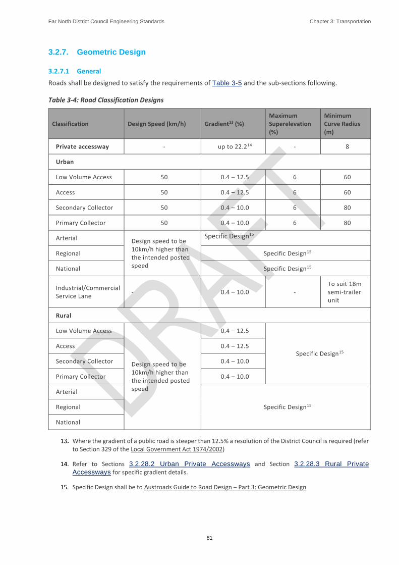
Far North District Council Engineering Standards Chapter 3: Transportation
81
3.2.7. Geometric Design
3.2.7.1 General
Roads shall be designed to satisfy the requirements of Table 3-5 and the sub-sections following.
Table 3-4: Road Classification Designs
Classification Design Speed (km/h) Gradient13 (%) Maximum Superelevation (%)
Minimum Curve Radius (m)
Private accessway - up to 22.214 - 8
Urban
Low Volume Access 50 0.4 – 12.5 6 60
Access 50 0.4 – 12.5 6 60
Secondary Collector 50 0.4 – 10.0 6 80
Primary Collector 50 0.4 – 10.0 6 80
Arterial Design speed to be 10km/h higher than the intended posted speed
Specific Design15
Regional Specific Design15
National Specific Design15
Industrial/Commercial Service Lane
- 0.4 – 10.0 - To suit 18m semi-trailer unit
Rural
Low Volume Access
Design speed to be 10km/h higher than the intended posted speed
0.4 – 12.5
Specific Design15 Access 0.4 – 12.5
Secondary Collector 0.4 – 10.0
Primary Collector 0.4 – 10.0
Arterial
Specific Design15 Regional
National
Where the gradient of a public road is steeper than 12.5% a resolution of the District Council is required (refer to Section 329 of the Local Government Act 1974/2002)
Refer to Sections 3.2.28.2 Urban Private Accessways and Section 3.2.28.3 Rural Private
Accessways for specific gradient details.
Specific Design shall be to Austroads Guide to Road Design – Part 3: Geometric Design

Far North District Council Engineering Standards Chapter 3: Transportation
82
3.2.7.2 Design Speed
The design speed of a road is the maximum speed that a vehicle can safely travel at on that road under perfect conditions. Many factors shall be considered and the Austroads Guide to Road Design - Part 3: Geometric Design (2016) provides suitable guidance for designing to a design speed. (NB: This Guide replaces that which was previously provided in the (separate) Austroads Urban and Rural Road Design Guides). Austroads Guide to Traffic Management – Part 8: Local Area Traffic Management also provides suitable guidance.
Traffic management facilities shall be included in the road design as necessary to ensure that the design speed environment is achieved.
3.2.7.3 Horizontal and Vertical Alignment
Horizontal and vertical alignment (including horizontal and vertical curves) shall be based on terrain and the design speed applicable to the road function.
The design speed of the vertical alignment shall not be less than that of the horizontal alignment. The design should provide for a consistent standard of alignment with no curve less than 15 km/hr lower than the 85th percentile operating speed at the site.
Reverse curves shall be separated by an adequate length of straight in metres being 0.7 times the posted speed limit.
Tracking curves (or demonstration of tracking by use of digital tracking software) may be required to show that vehicles can negotiate curves that are narrow in lane width or have a small radius. The vehicles chosen shall be appropriate to the type of vehicle that will use the road. Refer to RTS18 – NZ On-road Tracking Curves for Heavy Vehicles 2007 and note that tracking curves can be accessed at http:/www.nzta.govt.nz/resources/road-traffic-standards/rts-18.html
3.2.7.4 Curve Radius
The minimum centreline radius for roads shall be in accordance with Table 3-5.
3.2.7.5 Crossfall and Superelevation
The normal (minimum) crossfall for all sealed roads shall be 3%. Where existing features mean that this cannot be achieved the crossfall may vary between 2% and 4%. Single crossfall roads will be considered on urban access and low volume access roads where normal crossfall is unobtainable and shall have particular regard for stormwater management.
The crossfall for unsealed roads shall be 6% in all cases including where single crossfall is applied
Crossfall transitions between sealed and unsealed roads shall be developed in seal over a minimum length of 15 metres
Minor adjustments to kerb levels to provide an evenly sweeping kerb line are acceptable.
Normal maximum superelevation in urban environments shall be 6%.
Normal maximum superelevation in rural environments shall be 7%
3.2.7.6 Widening on Curves
In some instances, (e.g. low horizontal curve radius where the passage of vehicles has the potential to reduce safety), movement lanes shall be assessed to determine the need for localized additional width. For a two-lane road, curve widening should be omitted when the total widening is less than 0.5m.
The Austroads Guide to Road Design - Part 3: Geometric Design has useful guidance on this. Table 3-5
(adapted from Austroads) provides acceptable data for use in design.

Far North District Council Engineering Standards Chapter 3: Transportation
83
Table 3-5: Curve Widening per Lane for Design Vehicle
Curve Radius (m) Widening per lane (m)
11.5m large rigid truck 18m semi-trailer
60 0.7 0.8
80 0.5 0.6
100 0.4 0.5
140 0.3 0.3
200 0.2 0.2
>400 - -
3.2.7.7 Sight Distance
All roads All vehicle entrances shall be designed with sight distances that match the posted speed. Refer to Sheet 4.
Visibility splays and envelopes may require the road boundary to be set back in which case trees shall not be planted in the visibility splay. Sightlines outside the Transport Corridor will only be approved where the land between the sightline and the road reserve boundary, plus an additional 0.5m beyond the sightline, is appropriately protected such that no development is permitted within the affected area and the District Council has the legal right to trim or remove vegetation within that area. Easements or covenants are acceptable land protection instruments in this regard.
3.2.8. Cut / Fill Batters
3.2.8.1 Urban Roads
Cut and fill batters for roads shall be constructed within the Transport Corridor and comply with the following criteria:
Maximum grade of 20% (1:5) starting at the road boundary. Where circumstances dictate a steeper grade is necessary, a geotechnical assessment of the slope shall be provided together with specific access design,
Any retaining wall designed to support the road or footpath shall be constructed within the Transport Corridor and will likely require a building consent, and
Where the District Council considers that the stability of any planned embankment is in doubt, a stability analysis of the slope under saturated conditions may be required.
3.2.8.2 Rural Roads
Rural batters for cuttings and embankments shall usually be constructed inside the Transport Corridor and comply with the following criteria:
Batters less than 750mm high shall be cut at 1V:4H and shall be top soiled and grassed,
Batters greater than 750mm high shall be cut at 1V:2H and shall be protected from face erosion by hydro-seeding or similar, and

Far North District Council Engineering Standards Chapter 3: Transportation
84
Batters 4.5m high and above shall be assessed by a Geo-professional. In undertaking this check and determining the appropriate erosion protection the Geo-professional shall take into account:
i. The type of soils present in the cutting, and
ii. The degree of practicable erosion and its effect on long term stability, the safety of road users, and adjacent property owners
3.2.9. Intersections
3.2.9.1 General
Subject to the following provisions and the provisions of Section 0 Design Considerations, all intersections shall be designed in accordance with Austroads Guides to Road Design Parts 4 (Intersections and Crossings) and 4A (Unsignalised and Signalised Intersections).
Generally, roads should intersect only with roads in the same class or those immediately above or below in classification. T-junctions are preferred to cross intersections particularly for access roads. The angle of
intersection should be 90o, although a minimum angle of 70 o can be used when justified by other constraints. Carriageway alignment may be offset within the road reserve to improve the intersection angle.
Intersections on curves, particularly on the inside of curves, other than large radius curves, shall be avoided. Multi-leg intersections may require control by roundabouts.
Where Traffic Intensity threshold values as set out in the District Plan Rules are expected to be exceeded for a new development (inclusive of all access points), a Traffic Impact Assessment shall be submitted. Design Considerations
The location and design of intersections shall take into account the minimum sight distances shown in
Sheet 4.
The minimum permitted spacing between adjacent intersections on different categories of road is set out in Table 3-6. All distances are measured along the centreline of the major road between the centrelines of the intersecting roads.
Table 3-6: Minimum Intersection Spacing
Access (including low volume)
Secondary Collector Primary Collector Arterial
Urban 30m 50m 100m 100m
Rural 75m 100m 150m 150m
The minimum kerb radius at urban intersections shall be:
8m with corner splays of 4m to 6m for residential roads of collector class and below. A reduced kerb radius may be considered to enhance pedestrian facility in low speed environments subject to the approval of the District Council.
13.5m with corner splays of 6m for arterial roads and in commercial/industrial areas.
Corner splays in higher than 50 km/hr. speed environments shall be subject to Specific Design to ensure safe visibility at intersections
Major industrial intersections shall be specifically designed for 18m semi-trailer units, and all urban intersections (access roads and above) designed for a minimum 11.5m large rigid truck, as defined by the ‘RTS18’ tracking curves referenced in Section 3.2.7.3 Horizontal and Vertical Alignment.

Far North District Council Engineering Standards Chapter 3: Transportation
85
Gradients within 30m of urban intersections shall be:
a. for access roads - less than 1 in 33 where practicable and not greater than 1 in 10, or
b. for collector and arterial roads - less than 1 in 50
3.2.9.2 Arterial Road Intersections
For intersections with arterial roads, the Engineering Plans shall show the sight distance provided at each intersection, plus the following information:
Design Speed,
Design Vehicle,
Distance from limit lines to viewpoint (LV),
Approach Sight Distance (ASD),
Safe Intersection Sight Distance (SISD), and
All radii
The SISD shall be determined with an object of height 0.6m.
Reference can also be made to Austroads Guides to Road Design Parts 4, 4A, and 4C.
3.2.10. Roundabouts
Roundabouts may be required at multi-leg intersections, intersections where Stop or Give Way controls do not provide adequate capacity or Level of Service, or to provide traffic calming.
Roundabouts shall be subject to specific approval by the District Council and shall be designed in accordance with Austroads Guide to Road Design Part 4B: Roundabouts. The size of a roundabout has a significant role in the performance for capacity, traffic safety and turning movements of vehicles.
Visibility is an important factor to ensure safety standards are met, Austroads Guide to Road Design Part 4B: Roundabouts, Criteria 1 and 2 for sight distance are both mandatory requirements. Achievement of Criteria 3 is desirable.
3.2.11. Traffic Signals
Traffic signal installations shall be subject to Specific Design, safety auditing and approval processes to the satisfaction and final approval of the District Council. Developers are advised to consult with the District Council at an early stage to ascertain current requirements. (Note: the current – as at 2017 – standard is NZTA P43 Specification for Traffic Signals – modified by Far North District Council Regional Special Conditions).
3.2.12. Pavement Structural Design
3.2.12.1 General
Pavements shall be provided to all roads such that vehicle loads may be carried out without distress, in all weathers, for at least the design life with only normal routine maintenance and periodic re-surfacing.
Pavements (including carparks) shall be flexible granular pavements with thin surfacing layers. Where this is not sufficient or a more innovative solution can be implemented, it shall receive the prior approval of the District Council to proceed with the design – refer to Section 3.2.2.2 Alternative Designs and Section 1.5.1.2 Alternative Designs.

Far North District Council Engineering Standards Chapter 3: Transportation
86
Pavements shall be designed for the specified design life, based on the subgrade strength, traffic loading and traffic growth. Design loads shall be determined from the known and/or predicted heavy vehicle usage of the road, with adequate justification provided.
3.2.12.2 Design
A sealed pavement design may be carried out by one of two methods:
3.2.12.2.1. Sealed Pavement – Specific Design
This method shall be used for all industrial roads and all arterial and collector classifications (both urban and rural). It may also be used for roads of lower classifications.
The design shall be in accordance with the Austroads Guide to Pavement Technology – Part 2: Pavement Structural Design and the NZ Supplement to the Austroads Pavement Design Guide together with relevant NZTA pavement material standards.
Factors to be included in the design are:
Design Period - 30 years,
Trips generated per household per day – 10,
Annual Heavy Commercial Vehicle (HCV) growth factor - 3 % minimum unless otherwise specified by the District Council,
Load factor - the Presumptive ESA/HCV of 1.44 shall be used for design purposes unless otherwise specified by the District Council, and
% HCV - 5% urban access and collector roads; 7% urban arterial roads; 10% industrial and commercial; 9% all rural classifications.
Note: The above factors are the minimum values to be used for design purposes and the District Council may require site specific increased values where peer reviews indicate the need or where Council believe that circumstances exist where they can be justified.
The design report shall include the following information as a minimum:
Results of soils investigations,
Design assumptions and figures,
Material specifications,
Engineering drawings, and
QA measures for construction
3.2.12.2.2. Sealed Pavement – Default Design
This method may only be used for urban and rural access (including low volume) classifications. Using this design does not exempt the construction from any tests or compliance with any targets and does not provide any guarantee that the resulting pavement will comply with all testing requirements. Pavements shall comply with the depth and aggregate specified in the following table:
Table 3-7: Pavement Layer Thickness for Urban and Rural Classifications
Road Classification Sub-base Basecourse Notes
Low Volume Urban Access (< 200 vpd) 200 110 max 5% HCV
Urban Access (200 – 1,000 vpd) 250 130 max 5% HCV

Far North District Council Engineering Standards Chapter 3: Transportation
87
Road Classification Sub-base Basecourse Notes
Rural Access & Low Volume Access (< 200 vpd)
220 120 max 9% HCV
These typical designs are based on an insitu subgrade having a soaked CBR of 5 for a minimum depth of 0.6m. If the insitu subgrade does not achieve this strength, then subgrade improvements may be undertaken in order to achieve the required design subgrade CBR value. Refer per Section 3.2.12.2.1
Subgrade Testing for method of determining the design CBR.
If a subgrade of 0.6m depth and a CBR of 5 is not practicable, a Specific Design will be required as per Section 3.2.12.2.1 Sealed Pavement – Specific Design.
3.2.12.2.3. Unsealed Pavement
Unsealed pavements shall comprise a minimum compacted thickness of 300mm of well graded granular material with a minimum soaked CBR of 20. The maximum particle size shall be no greater than 100mm.
Unsealed pavements shall include an upper (non-structural) layer of well graded running coarse aggregate of maximum particle size 20mm, minimum layer thickness 50mm and containing sufficient fine materials to bind the layer and confine larger particles in the underlying structural pavement layer.
3.2.12.3 Subgrade Testing
The support provided by the subgrade is one of the most important factors to be considered in determining pavement design thickness, composition and performance. The level of support as characterised by the subgrade strength is dependent on the soil type, density and moisture conditions at construction and during service.
Subgrades are inherently variable in nature and reflect the changes in topography, soil type, and drainage conditions that occur along an existing or proposed road alignment. Hence the selection of a subgrade design value requires adequate consideration of the degree of variability within a particular development section, and the quantity and quality of data on subgrade properties. Therefore, the frequency of testing is critical to gaining a good understanding of the true nature of the subgrade. As a minimum, testing should be at intervals of ‘length + 50m / 100” or 5 whichever is greater in visually similar subgrade materials.
Where the extent of cut or fill is too great to make subgrade CBR testing feasible at the design stage, such testing shall be done on completion of earthworks and the pavement design amended accordingly and submitted to the District Council for re-approval.
Soaked CBR (laboratory test) values of the pavement subgrade shall be used, and the pavement designed for the estimated number of ESA loadings over the design life.
Unsoaked, or in-situ subgrade CBR tests in non-granular materials will be approved for private accessways serving no more than eight household units using a scala penetrometer testing from 0 to 1.0m below design subgrade level. Sheet 5 shows the correlation between scala penetration and CBR values. Taking the average value of the inferred CBR from the scala test results is not appropriate. Determine the design CBR as follows:
a. For subgrade strengths that are constant or improve with depth, the design CBR shall be the 10th percentile of the results obtained over the – i.e. the value below which 10% of the test results fall (or the value exceeded by 90% of the test results.)
b. For any weak layers encountered up to 1.0m below the design subgrade level and/or when subgrade improvements are required, the design CBR shall be determined using the nomograph on Sheet 5a
3.2.12.4 Peer Review
All specific pavement designs shall be required to be peer reviewed by an independent specialist approved by the District Council at the Developer’s cost. The peer review shall be submitted with the design

Far North District Council Engineering Standards Chapter 3: Transportation
88
documentation together with an explanation as to how the findings of the peer review have been addressed.
3.2.13. Road Surfacing
3.2.13.1 General
All new urban carriageways shall be surfaced with either a chip seal or asphaltic concrete. Permeable pavers will not be approved as a running surface for public roads. The use of concrete will require the specific approval of the District Council.
All new rural carriageways shall be surfaced with a chip seal unless specifically approved otherwise by the District Council through resource consent conditions.
All urban and rural private accessways shall be surfaced in accordance with the requirements of Sheet 7, Sheet 8, Sheet 9 and Sheet 10.
Asphaltic concrete (type to be approved by the District Council) applied over a waterproofing chip seal shall be used on industrial roads, roundabouts, all cul-de-sac turning heads, off street carparking areas and any other site subject to high turning movements as determined by the District Council. On cul-de-sac heads, asphalt shall be applied until the carriageway becomes a constant width.
3.2.13.2 Chip Seal Surfacing
The first coat shall be a two-coat grade 3/5 chip seal. A second coat of chip seal shall be applied between 12 and 18 months later as part of the development cost. Other chip seal designs may be considered and approved by the District Council. For further details and requirements see Section 3.3.5.3 First Coat Chip
Seal and 3.3.5.4 Second Coat Chip Seal and Resealing.
3.2.13.3 Asphaltic Concrete Surfacing
Asphaltic concrete may be used as an alternative surfacing to chip seal, however there are stricter requirements for pavement stiffness. Selection of an appropriate mix for industrial sites shall be agreed with the District Council. For further details and requirements see Section 3.3.5.2 Asphaltic Concrete
(AC).
3.2.14. Road Drainage
3.2.14.1 General
All roads shall be provided with facilities for the collection and disposal of both stormwater and subsoil water suitable to cope with a 1% AEP flood. Designs shall consider the following factors:
Groundwater recharge through soakage systems,
Quality of water discharged to receiving environments either directly or via connection to an existing piped network,
Requirements of the Northland Regional Council,
Overland flow paths. Urban and industrial roads should be lower than adjoining land and rural roads higher than surrounding farmland but should not obstruct natural overland flow paths,
Water discharged from adjoining land (including current and future land use),
Public safety,
Minimising of future maintenance requirements,
Far North District Council Engineering Standards Chapter 3: Transportation
89
Capacity of any existing piped network,
Cyclists,
Reduction of peak discharge rate, and
Compliance with Chapter 4:: Stormwater and Drainage of the ES including stormwater runoff design
In urban areas stormwater runoff should be controlled by kerb and channel. (Section 4.2.4 Discharge to
the Road Kerb details the limitations of kerb stormwater outlets). Alternative urban controls shall be designed to fit with the urban environment and to minimise maintenance requirements and will require specific approval. Channels constructed from clay or concrete pavers will not be approved.
The urban road drainage system shall include first flush treatment to meet or exceed Auckland Regional Council TP10 standards – refer to Section 3.2.14.6 Catch-Pits for catch-pit design requirements. Where ‘active’ or proprietary treatment devices are proposed, the type of device shall be approved by the District Council in order that maintenance requirements for such devices may be rationalised across the District.
Design criteria for components of the drainage system are as follows:
3.2.14.2 Subsurface Drainage
Subsurface drains shall be provided on both sides of all urban roads for pavement drainage purposes except where it can be demonstrated to the satisfaction of the District Council that it is not necessary - e.g. low water table and natural ground with high permeability – refer to Section 4.3.18 Subsoil Drains for further details. Rural roads in cut will require subsurface drainage - see Sheet 14.
Subsurface drains shall discharge to a suitable component of the stormwater system.
Where natural groundwater levels are known to be high, an effective means of de-watering shall be submitted for approval at the design stage. Such means to identify whether the measures shall be temporary, or form part of the permanent subsurface drainage system.
3.2.14.3 Side Drains, Water Tables
Stormwater from rural roads shall be directed to side drains/water tables or other approved system, sized to suit the flows discharging to them but not less than a 10% AEP rainfall event. The drains shall be designed to keep groundwater below the road subgrade and be located within the Transport Corridor. On all such drains where the gradient is steeper than 6.7% scour protection such as concrete, rock riprap, check dams, a combination thereof shall be provided. All outlets shall be protected from scour and located to minimise the risk of slope instability.
The discharge of stormwater shall not cause damage to the receiving property. The discharge of concentrated stormwater shall be subject to the approval of the affected property owner(s). Natural or non-concentrated stormwater shall be shown to be neither diverting catchments nor significantly changing peak flows or flow patterns.
Where physical constraints preclude the construction of side drains and/or the land is steep, unstable or prone to erosion, kerb & channel or similar may be required to be provided.
3.2.14.4 Swales
The use of swales will require the specific approval of the District Council before proceeding with design details. Where such approval is given, swales, raingardens and other low impact stormwater devices may be used to allow for infiltration to reduce peak discharge flows, and to provide stormwater treatment.
They should be located in the berm area and not in the centre of the road unless specifically approved by the District Council. All such devices shall:

Far North District Council Engineering Standards Chapter 3: Transportation
90
Be of a sufficient width to accommodate the devices, utility services (if needed), plant growth and to allow for maintenance,
Provide for vehicle and pedestrian crossing points as part of the design, and
Be designed by a suitably qualified person and comply with the requirements of Section 4.3.19 Infiltration Systems and Section 4.3.20 Stormwater Treatment and Detention
Devices.
Where swales are used in urban areas the road edge shall have a flush concrete edge and bollard (or similar) protection to prevent vehicles driving through them. The edge shall be 30MPa concrete, 300mm wide and 200mm deep with the top surface matching the crossfall of the carriageway. See Sheet 13. Refer to Section 3.2.27 Vehicle Entrances for the requirements for vehicle crossings over swales.
Refer also to Sheet 15 and Sheet 16 for typical details that may be used in swale design and to the NZTA Stormwater Treatment Standard for State Highway Infrastructure for further guidance.
3.2.14.5 Kerb and Channel
Subject to the provisions of Section 3.2.14.4 Swales, kerb and channel at a minimum gradient of 0.4% shall be provided on both sides of the carriageway for all urban carriageways. See Sheet 13.
Heavy duty kerb & channel shall be used in all industrial roads and service lanes. See Sheet 13.
Mountable kerb and channel shall be used on traffic islands and may be used on service lanes. In all other cases, mountable kerb and channel may only be used with the specific approval of the District Council.
Kerb and channel shall be provided on the uphill side of all urban roads with single crossfall to collect the stormwater runoff from footpaths and berms.
For rural roads, kerb and channel shall be required where necessary to control stormwater runoff such as adjoining cut and fill batters to control potential scouring of watertables and embankments.
3.2.14.6 Catch-Pits
Catch-pits shall be provided to accept the design flow, including kerb outlets and overland flow intercepted by the road from adjacent land, based on the catch-pit capacity (approximately 28 l/s for a single back entry catch-pit excluding allowance for catch-pit blockage).
Catch-pits shall be designed and constructed in accordance with the provisions of Section 4.3.17 Catch-
Pits.
In addition to the provisions of Section 4.3.17 Catch-Pits, catch-pits should also be located where flow could leave the channel (tangent points at intersections), and upstream of accessible (pram) crossing locations.
Catch-pit grates shall be cycle friendly with bars either transverse to the channel direction or closely spaced bars in a wavy pattern in a longitudinal direction.
Where proprietary ‘super catch-pits’ or back entry inlet catch-pits are proposed, they shall be designed and constructed in accordance with the manufacturer’s specifications. All non-standard catch-pits shall be specifically designed with allowance for partial blockage of the gratings. See Sheet 34 for standard catch-pit details.
3.2.14.7 Secondary Flow Provisions
At all points where catch-pit blockage may occur or where design capacity may be exceeded, which could lead to overflow into private property, provision shall be made for designed secondary flow paths protected by public ownership or easement.
For more information on overland flow path requirements and design refer to Section 4.3.8.3 Secondary
System Design Requirements – Overland Flow.

Far North District Council Engineering Standards Chapter 3: Transportation
91
3.2.15. Parking and Maneuvering
3.2.15.1 On Road Parking
The transport corridor shall be designed to accommodate the parking requirements contained in Table
3-2.
Parking bay pavement shall be constructed to the same standard as the road unless agreed otherwise by the District Council. Crossfall requirements are the same as for the carriageway.
3.2.15.2 Off Road Parking
Where dedicated off-road carparking is required, the quantity and location shall be provided in accordance with the District Plan. The following requirements shall be met:
The layout dimensions shall conform to the details shown in AS/NZS 2890.1:2004. Mobility parking spaces shall be designed in accordance with NZS 4121:2001. Loading bay spaces shall comply with AS 2890.2:2002. Refer also to District Plan for layout dimensions.
Adequate provision shall be made for access between the road and park ing area and for maneuvering within the site so that vehicles do not reverse out onto the road.
On-site maneuvering for cars and heavy goods vehicles shall comply with the vehicle tracking curves shown on Sheet 26, Sheet 27 and Sheet 28 as applicable. Maneuvering in and out of a parking/loading bay shall not require more than one reverse maneuver.
The gradient for off-street parking spaces, loading bays and associated maneuvering areas for all non-residential activities shall not be steeper than:
i. 1 in 16 for surfaces at 90° to the angle of parking, or
ii. 1 in 20 for surfaces parallel to the angle of parking.
Structural design shall comply with the requirements of Section 3.2.12 Pavement
Structural Design, and construction (including testing) shall comply with the requirements of Section 3.3.3 Pavement Construction and Section 3.3.4 Pavement Testing - the same as for roads. Unless approved otherwise through the resource consent conditions, surfacing shall comply with the requirements of Section 3.3.5 Pavement Surfacing.
3.2.16. No Exit Roads and Cul-de-sac Heads
3.2.16.1 No Exit Roads
‘No-exit’ roads shall not be provided where through roads and connected networks can be designed. Where no-exit urban roads cannot be avoided, they should incorporate sufficient measures to ensure safe connectivity for pedestrians and cyclists. They should also have clear no-exit signage at the major road intersection.
No-exit roads, whether public or private shall provide for road turning at the end of the road for an appropriate vehicle but in any event not less than an 11m rigid truck.
3.2.16.2 Cul-de-sac Head Design
The design of cul-de-sac turning areas shall be in accordance with Sheet 11 noting that in commercial and industrial areas the minimum radius shall be 15m to accommodate the turning movements of service vehicles.
Off-set turning heads shall be designed by offsetting the road carriageway crown to create symmetrical conditions, with the channel being designed accordingly.

Far North District Council Engineering Standards Chapter 3: Transportation
92
If a central area is proposed for parking or planting, the layout shall be checked for access by heavy vehicles (11.5m rigid truck) using tracking curves. The minimum trafficable width shall be 5.5m.
Hammerhead or ‘T’ cul-de-sacs may be provided in urban areas only where a standard circular head is not practicable. The layout shall be subject to Specific Design with particular consideration of vehicle entry/exits. Compliance with Figure 3.4 in NZS 4404:2010 is an acceptable solution in residential areas.
The minimum channel gradient around turning heads shall be 0.5%. The maximum long or cross section slope in turning heads shall be 6%. Appropriate drainage shall be provided with a double catch-pit required at the low point.
3.2.17. Road Lighting
3.2.17.1 General
Design of road lighting is to be in accordance with the NTA Design Manual Street Lighting.
3.2.18. Traffic Signs and Line Markings
Road design shall incorporate signage, roadmarking and the provision of traffic control devices (such as flush or raised medians, pedestrian refuges) appropriate to the place and link context. Access roads shall be designed to minimise the need for traffic signs and marking. Signs include Stop and Give-Way, directional arrows on islands, warning signs, delineation devices (edge marker posts) etc. Roadmarking includes marking of intersections, centrelines, parking areas etc.
Road marking and traffic signs shall comply with the Land Transport Rule: Traffic Control Devices 2004 and associated NZTA Traffic Control Devices Manuals.
Urban and rural roads shall be marked in accordance with Table 3-8 and Table 3-9.
Table 3-8: Road Marking - Urban
Type Criteria Delineation Posts
Centre line Edge Line RRPM’s Intersection Control
Low Volume Access
0 – 200 ADT X X X X ✓
Access 200 –1,000
ADT X ✓ X X ✓
Primary Collector
1,001 – 3,000 ADT
X ✓ May Be
required May Be
required ✓
Secondary Collector
3,001 – 5,000 ADT
X ✓ May Be
required May Be
required ✓
Arterial 5,001-15,000
ADT X ✓ ✓ ✓ ✓
Regional 15,001-25,000
ADT X ✓ ✓ ✓ ✓
National >25,001 ADT X ✓ ✓ ✓ ✓
Service Lane X May Be
required X X ✓

Far North District Council Engineering Standards Chapter 3: Transportation
93
Table 3-9: Road Marking – Rural (Sealed)
Type Criteria Delineation Posts
Centre line Edge Line RRPM’s Intersection Control
Low Volume Access 0 – 50 ADT
X X Inside Curves
X ✓
Access 51 – 200 ADT
X ✓ Inside Curves
X ✓
Primary Collector 201 – 1500 ADT
✓ ✓ ✓ May be required
✓
Secondary Collector
1000 – 3000 ADT
✓ ✓ ✓ ✓ ✓
Arterial 3000 – 10,000 ADT
✓ ✓ ✓ ✓ ✓
Regional 10,001 – 15,000 ADT
✓ ✓ ✓ ✓ ✓
National >15,001 ADT ✓ ✓ ✓ ✓ ✓
All signs on public roads shall have VIP standard or equivalent sheeting in accordance with AS/NZS 1906.1:2017. All other signs shall have Class 2 sheeting. The sign sheetings shall be designed to adhere fully to the backing for at least 10 years.
Sign supports on traffic islands shall be a recoverable or breakaway type.
3.2.19. Traffic Calming Devices
In order to achieve the desired design speed environment, traffic calming devices may be required within the Transport Corridor. Austroads Guide to Traffic Management and the NZTA Traffic Control Devices Manual should be used to guide development of these devices.
In residential access streets, traffic calming measures may also be used to enhance amenity values and safety and to discourage through traffic.
Traffic calming measures can include the provision of horizontal bends of significant deviation (450 or more), raised platforms, speed humps, traffic islands, raised pedestrian crossings, lane deflections, mini roundabouts and the like.
The provision of traffic calming measures should be discussed with the District Council at an early stage in the design. Safety audits and public consultation may be necessary depending on the situation and ultimately, the use of any such measure shall be subject to the specific approval of the District Council.
3.2.20. Bridges, Culverts and Other Structures
The Developer shall obtain all necessary resource consents (including Northland Regional Council) and/or building consents required for bridges, culverts, underpasses (pedestrian or stock) and retaining structures.
For any development where a bridge is proposed, the bridge concept plan shall be discussed and agreed with the District Council before detailed design commences.
All bridges, major culverts, underpasses and retaining structures shall be designed in accordance with the NZTA Bridge Manual (SP/M/022) and the design shall be carried out by an IQP.
Note: Culverts (including multiple culverts with a total waterway area greater than 3.4m2 are regarded as ‘major culverts’ under the NZTA Bridge Manual.

Far North District Council Engineering Standards Chapter 3: Transportation
94
Appendix D of the Bridge Manual (Lightly Trafficked Rural Bridges) shall not be used for bridges on public roads, except with the specific approval of the District Council.
3.2.20.1 Bridge and Culvert Design
Particular features that shall be considered/covered in the design shall include, but are not limited to:
3.2.20.1.1. Widths/Lengths
All bridges and culverts shall be designed with a width to accommodate movement lanes, cycle, and pedestrian needs of the road, in accordance with the road classification given in Table 3-2 and Table 3-3.
3.2.20.1.2. Safety Barriers
The design of the structure shall provide for the installation and fixing of all suitable barriers to cater for the needs of pedestrians, cyclists and vehicles, including the interaction between the various modes.
3.2.20.1.3. Batter Slope Protection
All culverts shall have anti-scour structures to protect batter slopes, berms, and carriageways.
3.2.20.1.4. Clearance Over Traffic Lanes
Where passing above traffic lanes, bridges shall have a full clearance height of 5.2 m to allow over-dimension vehicles to operate without a permit.
3.2.20.1.5. Foundations
All bridges and culverts shall be founded to resist settlement or scour. Abutments shall be designed to ensure bank stability and provide erosion or scour protection as applicable.
3.2.20.1.6. Provision for Services
The use of the structure as a service corridor shall be included in the design. This shall include consultation with utility providers to ascertain their current and future needs.
3.2.20.1.7. Inspection and Maintenance
The design shall include provision of any necessary access facilities to and within the structure in order to undertaken inspection and maintenance activities.
3.2.20.2 Bridge and Culvert Hydraulic Design
Waterway hydraulic design shall be carried out by an IQP in accordance with Chapter Chapter 4:
Stormwater and Drainage.
The total waterway shall be designed to achieve:
No exacerbation of existing upstream water levels during a 20% (plus climate change) AEP flood event,
Able to pass a 1% (plus climate change) AEP flood without significant damage to the road and waterway structures, and
Obstructions and risk of blockage in the waterway area are minimised.
In terms of traffic serviceability, the bridge or culvert shall also achieve:
On roads carrying > 3000 vpd, no interruption to traffic during a 1% (plus climate change) AEP flood event, or
For roads carrying between 250 and 3000 vpd, no interruption to traffic during a 2% (plus climate change) AEP flood event, or
Far North District Council Engineering Standards Chapter 3: Transportation
95
For roads carrying < 250 vpd, no interruption to traffic during a 10% (plus climate change) AEP flood event.
3.2.20.3 Bridges on Private Accessways
For bridges on private accessways serving up to eight household units, the design requirements of Appendix D of the NZTA Bridge Manual are minimum requirements and may be used, subject to the following conditions:
The access will not become a through route,
The alignment has a speed value below 70 km/hr.,
Use by logging trucks or similar is unlikely, and
No significant overloads are expected to occur, or the bridge can be bypassed.
Note that Appendix D of the NZTA Bridge Manual allows the replacement of the HN design load with 0.85 HN. The HO load need not be considered.
The level of side protection shall be appropriate to the situation. The minimum acceptable shall be the provision of kerbs and marking posts where the height above the watercourse is no more than 1.0m.
3.2.21. Footpaths and Pedestrian Accessways
Pedestrians and cyclists shall be provided for in accordance with Table 3-2 and Table 3-3.
3.2.21.1 Urban Footpaths and Accessible Crossings
Footpaths shall be set back a minimum 1.2m from the kerb unless physical constraints dictate otherwise and or located in a cul-de-sac. See Sheet 12.
Footpaths shall comply with the following:
The preferred minimum width shall be 1.8m (absolute minimum width 1.6m not including kerb width where adjacent to kerb) and noting that in areas with high concentrations of pedestrians such as shopping areas, community facilities, schools etc. and where angl ed parking is provided adjacent to the footpath, Specific Design shall apply in consultation with the District Council.
Footpaths shall have the minimum clear width between or around obstructions such as power poles, lighting columns, transformers and the like.
Crossfall shall typically be maximum 2% sloping towards the kerb and channel. Short sections of localised crossfall of up to 3% may be considered where levels make the typical crossfall impracticable. Crossfall in high pedestrian use areas such as shopping centres shall be 1% wherever practicable. Subject to approval from the roading manager.
Longitudinal gradient of footpaths shall match that of the road and shall not exceed 12.5%. 1 in 20 or 5%
New footpaths shall be constructed in concrete unless specifically approved otherwise by the District Council.
Accessible (pram and wheelchair) crossings shall be provided at all kerbed intersections and pedestrian crossings. Catchpits shall be sited on the upstream side of the crossings where practicable. The crossing entrance shall be connected to the footpaths and have a maximum gradient of 1 in 12 or 8.3% and shall not create break over angles that are unsafe for, or not traversable by mobility devices.

Far North District Council Engineering Standards Chapter 3: Transportation
96
Construction details for footpaths and pram crossings are described further in Section 3.3.7 Footpaths,
Cycleways and Vehicle Crossings and shown on Sheet 12 and Sheet 17 respectively.
3.2.21.2 Rural Footpaths
Footpaths shall be provided and constructed in the rural environments where required by resource consent conditions. These may be located adjacent to lot boundaries, separated from the carriageway by a watertable drain. They shall be designed to accommodate cyclists
Where not specifically required by resource consent conditions, the berm shall be formed and grassed so that it is suitable for pedestrian use.
In any rural environment the provision of safety footpaths may be required because of the scale or type of development, and/or hazards from traffic.
3.2.21.3 Pedestrian Accessways
Pedestrian accessways may be provided to link one urban road to another (especially no-exit roads) in order to improve connectivity and/or where they would offer a significantly shorter walking route from a road to a reserve or shopping centre etc.
Such accessways shall be designed for user safety and comply with the following:
They shall be created as either an easement in gross in favour of the District Council or a separate lot and should be visible from end to end and preferably no greater than 2 properties long,
The minimum formed width shall be 3.0m if also acting as a cycleway and constructed to a standard not less than that for footpaths. The minimum legal width shall be 1.0m wider than the formed width,
Provision shall be made for stormwater disposal,
Where barriers are provided to prevent vehicular access, provision shall be made for mobility scooter and wheelchair access, and
3.2.22. Facilities for Vision Impaired Pedestrians
Facilities for visually impaired pedestrians (i.e. TGSI - tactile ground surface indicators) shall be installed in accordance with NZTA Specification RTS14: Guidelines for Facilities for Blind and Vision Impaired Pedestrians at:
Crossing points at arterial or collector roads, including pedestrian throat islands, refuge islands and median islands,
Signalised intersections and signalized pedestrian crossings,
Zebra crossings, and
Other areas of high pedestrian activity such as shared zones, pedestrian malls, shopping centres.
3.2.23. Cycle Facilities
Cyclists are generally expected to share the movement lanes on roads. Where a shared off-road cycleway/footpath or a dedicated cycleway is required or where good design requires separation from the carriageway, the facilities shall be generally designed in accordance with the Austroads Guide to Road Design - Part 6a: Pedestrian and Cyclist Paths. Consideration will also be given to designs which have been developed using these standards listed reference documents.

Far North District Council Engineering Standards Chapter 3: Transportation
97
Off-road facilities designed for use by cyclists and shared with pedestrians shall have a minimum width of 3.0m unless specified otherwise by resource consent conditions. Off road cycle ways and/or shared paths shall have a maximum gradient of 5% 12.5%, a minimum lateral clearance of 700mm and a minimum overhead clearance of 2.5m from any fixed object (including trees) and shall be surfaced with either concrete or asphaltic concrete.
On road cycle lanes shall be surfaced with either chip seal or asphaltic concrete and marked to the NZTA’s Traffic Control Devices Manual requirements.
3.2.24. Berms
3.2.24.1 General
Berms shall be provided between the edge of the formed carriageway and the road legal boundary to accommodate footpaths, road signs, road lighting, underground services, landscaping and grass areas.
Berms shall be of adequate width to:
Achieve safe clearances between the carriageway edge and any obstacle (minimum clearance 600mm urban and 1500mm rural),
Allow running of utility services within the berm, between the back of footpath and the road legal boundary
Provide adequate space between the road reserve boundary and the carriageway edge to enable residents to safely enter the road traffic,
Allow for efficient road edge and edge drain maintenance,
Allow for the effective operation and maintenance of any form of stormwater management device,
Allow for adequate growth of plants/trees and ease of their ongoing maintenance, and
Allow for use of a lawnmower for general maintenance - narrow grass strips less than 1.2m wide shall be avoided.
3.2.24.2 Urban Berms
Berm crossfall shall typically be 4%, however localised grass berm cross falls may range between 2% and 10% but shall be able to be easily mown by the adjacent property owner. Engineering drawings should identify any variances from the typical crossfall and demonstrate that vehicle crossings can be satisfactorily negotiated by a standard design vehicle as shown on Sheet 26 and in accordance with Sheet 23 (breakover angles).
The berm crossfall shall slope towards the road.
Stormwater runoff from berms shall not be concentrated so as to pond, flood or cause a nuisance on any adjacent lot or adversely affect pedestrian use of footpaths.
Berms shall be topsoiled to a compacted depth of not less than 100mm nor greater than 300mm and grassed. See Section 3.3.8 Berms for construction details.
3.2.24.3 Rural Berms
Where practicable, rural berms should be constructed to the same standard as urban berms. Provision shall be made for footpaths in accordance with Section 3.2.12.2 Design Footpaths.
Where existing or proposed road culverts are discharging onto adjoining properties the culverts shall be extended to the road reserve boundary to enable continuous unrestricted pedestrian access.

Far North District Council Engineering Standards Chapter 3: Transportation
98
Batter slopes shall be topsoiled and grassed or if necessary, hydroseeded.
3.2.25. Trees and Landscaping
Landscaping including structures and street trees shall not compromise sight lines, underground services, or the safety of road users, cyclists and pedestrians. Trees shall not be planted within 8m of light standards and power poles, within 3m of vehicle crossings, within 5m of bus stops and within 12m of pedestrian crossings.
The mature size of any tree or garden planting shall be assessed for each planting location and shall be in scale with the surrounding street environment. Plants located in the sight triangle of intersections, or other traffic or vehicle/pedestrian conflict areas should not exceed 450mm in height when mature. Street trees shall be suitably located and have formative pruning to ensure optimal traffic sightline visibility from when they are first planted through to maturity.
All proposed berm planting and landscaping structures shall be shown on the engineering drawings submitted for approval and the design shall be in accordance with Error! Reference source not found.
Error! Reference source not found. of the ES. The approval of the District Council will be required for all such plantings and structures. The Developer is encouraged to discuss landscape concepts with the District Council to ensure the suitability of the proposal and consistency with the ES. It is preferable for this process to take place prior to applying for resource consent.
Street trees and other planting are considered to be assets for the purposes of as-built information.
3.2.26. Road Names and Signs
Names for new roads (including private roads and accessways serving five or more lots), will be determined by the District Council in accordance with their FNDC Policy #0064 - Road Naming. The Developer shall submit three names to the District Council for approval in order of preference well in advance of the vesting of the road (or the creation of the title or easement for private accessways).
Road name signs shall be in accordance with Table 3-10 below and comply with the details in Sheet 24 and Sheet 25.
Table 3-10: Road Name Signage
Parameter Urban and Rural Arterial Roads
All Other Public Roads
Private Roads and Accessways
Blade Size 200mm 150mm 150mm
Background Colour Blue Blue White
Letter Colour White White Blue
Letter Height 150m 100mm 100mm
Letter Type Transport Transport Transport
‘No exit’ supplementary blades shall be erected on all cul-de-sac and dead-end road signage.
‘Private access’ supplementary blades shall be erected on all private road and accessway signage.
The District Council logo shall only be placed on public road signage.
All signage shall be erected at intersections.

Far North District Council Engineering Standards Chapter 3: Transportation
99
3.2.27. Vehicle Entrances
3.2.27.1 General
Where a site has frontage to more than one road, the vehicle entrance shall be onto the road that has the lower class in the roading hierarchy.
The number of vehicle crossings per allotment shall not exceed those shown in Table 3-12.
Table 3-11: Maximum Number of Vehicle Crossings per Allotment
Frontage (m)
Low Volume Access
Access Secondary Collector
Primary Collector
Arterial Regional National
0 - 16 1 1 1 1 1
Specific Approval 17 - 60 2 2 1 1 1
61 -100 3 3 2 1 1
>100 3 3 3 2 1
Notes:
1. The frontage measurement will only apply to the road front approved for gaining entrance
2. Paddock entrances in rural Environments, with less than 10 vehicle movements per month, are exempt from the provisions of this Table
3. This Table does not apply to service stations where they comply with the NZTA’s Guidelines for Service Stations.
The minimum distance of a vehicle entrance from an intersection is shown in Table 3-13. Distances are measured along the centreline of the frontage road from the centreline of the vehicle entrance to the edge of the carriageway of the intersecting road.
Table 3-12: Minimum Distance of Vehicle Crossing from Intersections
Intersecting Road Classification (distance in metres)
Frontage Road National Regional Arterial Primary and
Secondary
Collector
Access and Low
Volume Access
Speed Limit up to 50 km/hr.
National Specific Design
Regional
Arterial 70 70 70 55 35
Primary and Secondary
Collector 40 40 40 40 20
Access and Low Volume Access
25 25 25 25 10
Speed Limit over 50 km/hr.
National Specific Design
Regional
Arterial 180 180 180 180 90
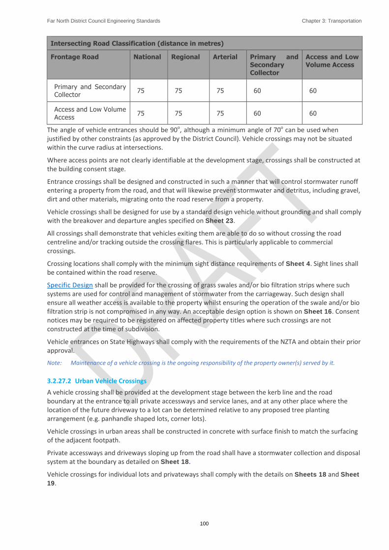
Far North District Council Engineering Standards Chapter 3: Transportation
100
Intersecting Road Classification (distance in metres)
Frontage Road National Regional Arterial Primary and
Secondary
Collector
Access and Low
Volume Access
Primary and Secondary Collector
75 75 75 60 60
Access and Low Volume
Access 75 75 75 60 60
The angle of vehicle entrances should be 90o, although a minimum angle of 70o can be used when justified by other constraints (as approved by the District Council). Vehicle crossings may not be situated within the curve radius at intersections.
Where access points are not clearly identifiable at the development stage, crossings shall be constructed at the building consent stage.
Entrance crossings shall be designed and constructed in such a manner that will control stormwater runoff entering a property from the road, and that will likewise prevent stormwater and detritus, including gravel, dirt and other materials, migrating onto the road reserve from a property.
Vehicle crossings shall be designed for use by a standard design vehicle without grounding and shall comply with the breakover and departure angles specified on Sheet 23.
All crossings shall demonstrate that vehicles exiting them are able to do so without crossing the road centreline and/or tracking outside the crossing flares. This is particularly applicable to commercial crossings.
Crossing locations shall comply with the minimum sight distance requirements of Sheet 4. Sight lines shall be contained within the road reserve.
Specific Design shall be provided for the crossing of grass swales and/or bio filtration strips where such systems are used for control and management of stormwater from the carriageway. Such design shall ensure all weather access is available to the property whilst ensuring the operation of the swale and/or bio filtration strip is not compromised in any way. An acceptable design option is shown on Sheet 16. Consent notices may be required to be registered on affected property titles where such crossings are not constructed at the time of subdivision.
Vehicle entrances on State Highways shall comply with the requirements of the NZTA and obtain their prior approval.
Note: Maintenance of a vehicle crossing is the ongoing responsibility of the property owner(s) served by it.
3.2.27.2 Urban Vehicle Crossings
A vehicle crossing shall be provided at the development stage between the kerb line and the road boundary at the entrance to all private accessways and service lanes, and at any other place where the location of the future driveway to a lot can be determined relative to any proposed tree planting arrangement (e.g. panhandle shaped lots, corner lots).
Vehicle crossings in urban areas shall be constructed in concrete with surface finish to match the surfacing of the adjacent footpath.
Private accessways and driveways sloping up from the road shall have a stormwater collection and disposal system at the boundary as detailed on Sheet 18.
Vehicle crossings for individual lots and privateways shall comply with the details on Sheets 18 and Sheet
19.

Far North District Council Engineering Standards Chapter 3: Transportation
101
3.2.27.3 Commercial and Industrial Crossings
All lots in areas zoned for commercial or industrial activity and all developments in other zones for commercial or industrial activities shall have an industrial standard crossing. Dimensions and construction details are provided in Sheets 19 and Sheet 22.
3.2.27.4 Rural Vehicle Crossings
A vehicle crossing shall be provided at the development stage at the entrance to all private accessways and at any other place where the location of the future driveway to a lot can be determined relative to any proposed tree planting arrangement (e.g. panhandle lots).
On sealed roads, vehicle crossings shall be sealed to the road boundary or for a minimum distance of 10m from the edge of the carriageway (whichever is the greater) and to a standard not less than that of the adjoining road surface. Asphaltic concrete or concrete may be used as alternative to chip seal. Where the access slopes up from a sealed road the crossing shall be sealed a minimum distance of 10m from the edge of the carriageway and designed to ensure debris does not get flushed onto the road creating a danger to cyclists and motorcyclists (e.g. initial negative gradient away from the road).
If the access slopes away from the road, an area not less than 3m long shall be provided from the edge of the carriageway at a gradient not exceeding 3%.
The crossing shall not obstruct any drainage facilities within the berm. Where the drain is shallow and only carries low rain flow, the crossing may pass through the drain. Where the drain is of an unsuitable shape or carries significant rain flow the drain shall be piped under the crossing. Pipes and end treatments shall be sized appropriately for the catchment intercepted but shall be a minimum 300mm diameter. Traversable culvert safety ends complying with NZTA Specification M23 shall be constructed to minimize safety risk and eliminate culvert end snagging hazards.
Rural crossings shall be designed to accommodate the largest vehicle that is likely to access the site.
Vehicle crossings for individual lots and private accessways shall comply with the following:
Type 1A A basic entrance with flares but no local widening as shown on Sheet 21
Type 1B Shall be used for dairy tanker entrances and the like as shown on Sheet 21
Type 2 A basic entrance with some local widening as shown on Sheet 21
Type 3 The same as the NZTA’s ‘Diagram D’ standard (as described and shown in Appendix 5B of the NZTA
Planning Policy Manual) except that 3 of the 4 tapers shall be 1:20 rather than 1:10 – those tapers
being both tapers on the opposite road from the crossing and the taper for a vehicle decelerating to turn
left into the entrance
Type 4 A right turn bay and/or full left turn lane marked out in accordance with the Manual of Traffic Signs
and Markings for the operating speeds of non-turning vehicles as they approach the entrance.
Criteria for the entrance crossing types are given in Figure 3-1 and Figure 3-2. Note that these Figures do not apply to rural intersections. They relate only to private rural entrances including private accessways.

Far North District Council Engineering Standards Chapter 3: Transportation
102
Figure 3-1: Criteria for Vehicle Entrance Types (Rural)
Figure 3-2: Criteria for Vehicle Entrance Types (Rural) - Extended
For Types 2 & 3 the criteria shall be applied separately to each direction of turn into the entrance crossing. It is acceptable for entrances to have different treatment types on each side of the main road provided the expected volumes of each turn have been assessed by a traffic engineering IQP. With Types 2 & 3 treatments the left turn component applies to the widening on the same side of the main road and the right turn component applies to the widening on the opposite side of the main road.
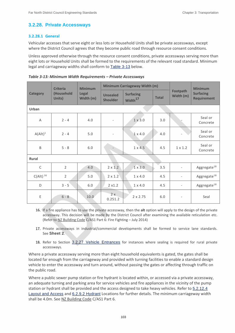
Far North District Council Engineering Standards Chapter 3: Transportation
103
3.2.28. Private Accessways
3.2.28.1 General
Vehicular accesses that serve eight or less lots or Household Units shall be private accessways, except where the District Council agrees that they become public road through resource consent conditions.
Unless approved otherwise through the resource consent conditions, private accessways serving more than eight lots or Household Units shall be formed to the requirements of the relevant road standard. Minimum legal and carriageway widths shall conform to Table 3-13 below.
Table 3-13: Minimum Width Requirements – Private Accessways
Category Criteria (Household Units)
Minimum Legal Width (m)
Minimum Carriageway Width (m)
Footpath Width (m)
Minimum Surfacing Requirement
Unsealed Shoulder
Surfacing
Width17
Total
Urban
A 2 - 4 4.0 - 1 x 3.0 3.0 - Seal or
Concrete
A(Alt)1 2 - 4 5.0 - 1 x 4.0 4.0 - Seal or
Concrete
B 5 - 8 6.0 - 1 x 4.5 4.5 1 x 1.2 Seal or
Concrete
Rural
C 2 4.0 2 x 1.2 1 x 3.0 3.5 - Aggregate18
C(Alt) 16 2 5.0 2 x 1.2 1 x 4.0 4.5 - Aggregate18
D 3 - 5 6.0 2 x1.2 1 x 4.0 4.5 - Aggregate18
E 6 - 8 10.0 2 x
0.251.2 2 x 2.75 6.0 - Seal
If a fire appliance has to use the private accessway, then the alt option will apply to the design of the private accessway. This decision will be made by the District Council after examining the available reticulation etc. (Refer to NZ Building Code C/AS1 Part 6: Fire Fighting – July 2014)
Private accessways in industrial/commercial developments shall be formed to service lane standards. See Sheet 2.
Refer to Section 3.2.27 Vehicle Entrances for instances where sealing is required for rural private accessways.
Where a private accessway serving more than eight household equivalents is gated, the gates shall be located far enough from the carriageway and provided with turning facilities to enable a standard design vehicle to enter the accessway and turn around, without passing the gates or affecting through traffic on the public road.
Where a public sewer pump station or fire hydrant is located within, or accessed via a private accessway, an adequate turning and parking area for service vehicles and fire appliances in the vicinity of the pump station or hydrant shall be provided and the access designed to take heavy vehicles. Refer to 5.2.12.4
Layout and Access and 6.2.9.2 Hydrant Locations for further details. The minimum carriageway width shall be 4.0m. See NZ Building Code C/AS1 Part 6.

Far North District Council Engineering Standards Chapter 3: Transportation
104
Where a private accessway contains public water and/or sewer reticulation the legal width may shall be increased to accommodate the minimum clearances required by Table 4-9.
Easements in gross in favour of the District Council may be required to be created over accessways
containing public utility services.
Provided the subgrade CBR (in-situ test) is not less than 7, the construction may be in accordance with Sheet 7, Sheet 8, Sheet 9 and Sheet 10. Where the subgrade CBR is less than 7, the pavement shall be specifically designed by an IQP.
3.2.28.2 Urban Private Accessways
The maximum gradient shall be:
12.5% for the first 5m from the road reserve boundary, and
22.2% for the remainder.
The crossfall shall be 3%.
On all urban private accessways in excess of 100m long and less than 4.5m carriageway width, passing bays shall be provided at points of intervisibility (at approximate 50m intervals). For such passing bays the carriageway width should be increased to 5.5m over a 15m length including 5m tapers at each end.
Surface water from the accessway shall be collected in a catch-pit and/or directed to a stormwater control or reticulation system with an approved outfall location. Generally, no discharge will be permitted directly to the kerb. It shall not discharge over a footpath or directly onto a road carriageway. Where accesses fall away from the road, stormwater control shall be provided as necessary to ensure that stormwater from the access does not concentrate onto any lot. See also Section 3.2.27 Vehicle Entrances. Stormwater attenuation and treatment shall comply with the requirements of Chapter Chapter 4: Stormwater and
Drainage.
Private accessways shall comply with the construction requirements of Section 3.3.9 Private Accessways and the details on Sheet 7 and Sheet 8.
3.2.28.3 Rural Private Accessways
The maximum gradient shall be:
12.5% for the first 5m from the road reserve boundary, and
22.2% for the remainder.
The crossfall shall be 3% (sealed) or 6% (unsealed)
All accessways in the Rural Living environments shall be sealed. In other rural environments all accessways serving six household units or more shall be sealed and/or where the gradient exceeds 12.5%
On all rural private accessways in excess of 200m long and less than 4.5m carriageway width, passing bays shall be provided at points of intervisibility (at approximate100m intervals). For such passing bays the carriageway width should be increased to 5.5m over a 15m length including 5m tapers at each end.
Where an unsealed accessway joins a sealed road, the accessway shall be sealed from the edge of the seal for a minimum length of 20m to prevent metal migrating onto the road. In addition, the provisions of Section 1.3.27 Vehicle Entrances shall apply for the crossings.
Surface water from the accessway shall not be permitted to concentrate onto any lot which could be at risk of instability or erosion and shall comply with the requirements of Chapter Chapter 4: Stormwater and
Drainage.
Similarly, surface water from the road reserve shall be prevented from flowing onto a private accessway in an uncontrolled manner.

Far North District Council Engineering Standards Chapter 3: Transportation
105
On all side drains where the gradient is steeper than 6.7% scour protection such as concrete, rock riprap, check dams, a combination thereof or similar shall be provided. All outlets shall likewise be protected from scour and located to minimise the risk of slope instability.
Private accessways shall comply with the construction requirements of Section 3.3.9 Private Accessways and the details on Sheet 9 and Sheet 10.
3.3. Construction
3.3.1. General
Road construction shall be carried out to the requirements and standards of the District Council approved drawings and specifications so as to achieve the intended design life. Where there is conflict between the approved documents and the ES, the ES shall take preference.
Road construction includes all associated construction within the Transport Corridor, together with private road and accessway construction, and applies equally to new works and to upgrading works.
3.3.2. Pavement Materials
These requirements apply to flexible pavements for public and private roads and for private accessways. For rigid pavements such as concrete refer to Austroads guides.
The design may utilise high strength materials (e.g. NZTA M/4 basecourse), or lower strength modified materials (e.g. lime or cement stabilised GAP 40 basecourse). The designer shall specify the material standards required by the design.
The Developer shall provide test data to confirm compliance with the specified material standards required for the design.
3.3.2.1 Granular Rock Fill Material (when used as a Subgrade Improvement Layer)
This material is a non-specific quarry aggregate suitable for use as a subgrade improvement layer. Lime rock is not acceptable as a granular fill.
This sub-base material shall have minimum soaked CBR of 20 and a nominal maximum size.
The material shall be suitably graded, moderate to highly weathered quarry rock with sufficient fines to aid compaction. A minimum of 10% by dry mass shall be unweathered (blue) material to ensure a level of durability.
The source of supply of all materials shall be nominated and the material shall be tested to ensure the CBR requirement can be achieved, and test results shall be provided. The material shall have the following properties:
a. A crushing resistance not less than 80 kN
b. Well graded with grading such that 100% of the material is less than 75mm maximum size with no more than 65% passing a 19.0mm sieve and 3% - 18% passing a 1.18mm sieve
c. A sand equivalent equal to or greater than a value of 20
Evidence of these properties will be required for approval by the District Council
3.3.2.2 Aggregate Pavement Layers
GAP aggregates shall comprise crushed aggregate and shall be free of all non-mineral matter. GAP 65 is a commonly used suitable sub-base material and lime stabilised GAP 40 a commonly used suitable basecourse material. Use of other complying materials is not precluded – e.g. NZTA M/4.
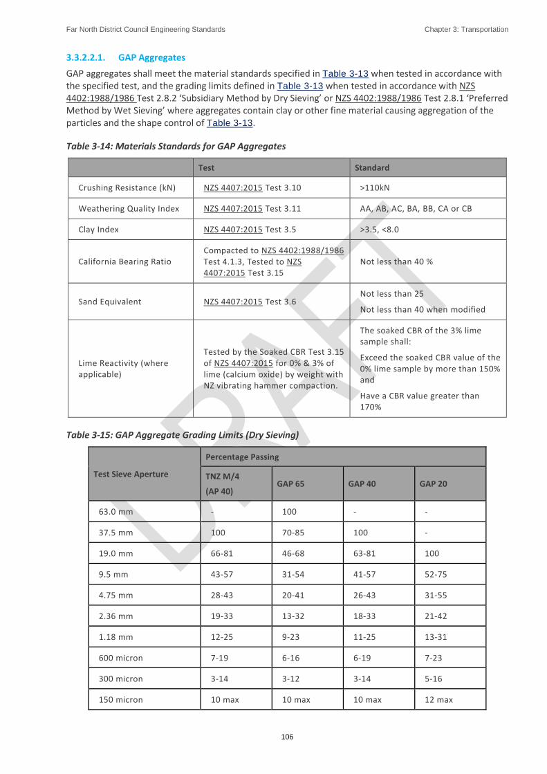
Far North District Council Engineering Standards Chapter 3: Transportation
106
3.3.2.2.1. GAP Aggregates
GAP aggregates shall meet the material standards specified in Table 3-13 when tested in accordance with the specified test, and the grading limits defined in Table 3-13 when tested in accordance with NZS 4402:1988/1986 Test 2.8.2 ‘Subsidiary Method by Dry Sieving’ or NZS 4402:1988/1986 Test 2.8.1 ‘Preferred Method by Wet Sieving’ where aggregates contain clay or other fine material causing aggregation of the particles and the shape control of Table 3-13.
Table 3-14: Materials Standards for GAP Aggregates
Test Standard
Crushing Resistance (kN) NZS 4407:2015 Test 3.10 >110kN
Weathering Quality Index NZS 4407:2015 Test 3.11 AA, AB, AC, BA, BB, CA or CB
Clay Index NZS 4407:2015 Test 3.5 >3.5, <8.0
California Bearing Ratio Compacted to NZS 4402:1988/1986 Test 4.1.3, Tested to NZS 4407:2015 Test 3.15
Not less than 40 %
Sand Equivalent NZS 4407:2015 Test 3.6 Not less than 25
Not less than 40 when modified
Lime Reactivity (where applicable)
Tested by the Soaked CBR Test 3.15 of NZS 4407:2015 for 0% & 3% of lime (calcium oxide) by weight with NZ vibrating hammer compaction.
The soaked CBR of the 3% lime sample shall:
Exceed the soaked CBR value of the 0% lime sample by more than 150% and
Have a CBR value greater than 170%
Table 3-15: GAP Aggregate Grading Limits (Dry Sieving)
Test Sieve Aperture
Percentage Passing
TNZ M/4
(AP 40) GAP 65 GAP 40 GAP 20
63.0 mm - 100 - -
37.5 mm 100 70-85 100 -
19.0 mm 66-81 46-68 63-81 100
9.5 mm 43-57 31-54 41-57 52-75
4.75 mm 28-43 20-41 26-43 31-55
2.36 mm 19-33 13-32 18-33 21-42
1.18 mm 12-25 9-23 11-25 13-31
600 micron 7-19 6-16 6-19 7-23
300 micron 3-14 3-12 3-14 5-16
150 micron 10 max 10 max 10 max 12 max

Far North District Council Engineering Standards Chapter 3: Transportation
107
Test Sieve Aperture
Percentage Passing
TNZ M/4
(AP 40) GAP 65 GAP 40 GAP 20
75 micron 7 max 6 max 7 max 8 max
Aggregate shape control shall comply with Table 3-13.
Table 3-16: Aggregate Grading Shape Control
Fractions
Percentage of Material in Fraction
TNZ M/4
(AP 40) GAP 65 GAP 40 PAP 20
37.5 – 9.5 mm - 24-46 - -
19.0 – 4.75 mm 28-48 15-37 27-49 -
9.5 – 2.36 mm 14-34 10-31 13-34 19-47
4.75 – 1.18 mm 7-27 7-25 7-28 8-35
2.36 mm – 600 micron 6-22 6-19 6-22 6-27
1.18 mm – 300 micron 5-19 5-16 5-19 3-21
600 – 150 micron 2-14 2-12 2-14 2-17
3.3.2.2.2. Equivalent TNZ M/4 AP40 Quality Basecourse Material
“Equivalent TNZ M/4 AP40 quality basecourse” must comply with all parts of the TNZ M/4 Specification except those requirements which are directly reduced by the allowance of the use of GAP 40 material as specified. These are as follows:
a. Crushing resistance can be as low as 120kN instead of 130kN;
b. Weathering quality index "CB" acceptable in addition to normal TNZ M/4 range;
c. Sand equivalent of GAP 40 aggregate prior to modification can be as low as 28 (modified must comply with TNZ M/4 requirement of 40);
d. Aggregate Grading Envelope & Shape Control prior to modification to comply with GAP 40 requirements specified in Table 3-15. The equivalent TNZ M/4 AP40 Quality Basecourse need not comply with TNZ M/4 grading requirements, however, after stabilisation the maximum particle size shall not be less than 26.5mm.
Alternatively, material fully complying with the TNZ M/4 Specification may be used.
3.3.2.2.3. GAP 20 Running Course
The running course of an unsealed pavement shall consist of GAP 20 aggregate with the following properties:
a. A crushing resistance of 110kN to 230kN when tested in accordance with NZS 4407:2015 Test 3.10,
b. A clay index greater than 3.5 and less than 10.0 when tested in accordance with NZS 4407:2015 Test 3.5,

Far North District Council Engineering Standards Chapter 3: Transportation
108
c. Meet the grading limits of Table 3-15.
Aggregate sources that produce stones that are hard, elongated and with sharp cutting edges capable of puncturing car tyres shall not be used.
3.3.3. Pavement Construction
3.3.3.1 Subgrade Layer
The subgrade may be fill or undisturbed material and shall be free of organic matter and other harmful material. It shall be constructed to meet the requirements of the pavement design and NZTA’s Specification F/1 - Earthworks Construction. Wherever practicable, the natural insitu material shall be used in construction of the subgrade by implementing compaction or other methods of modification to meet the required subgrade strength. Such methods of modification may include:
Lime or cement stabilization,
Use of geotextile fabrics and/or grids,
Drying and re-compaction of material,
Subgrade drainage improvements, or
A combination of the above
Where the insitu material is unsuitable to be used as subgrade, it shall be replaced by imported subgrade material fit for purpose and shall be subject to approval by the District Council before use – see Section 3.3.2.1 Granular Rock Fill Material (when used as a Subgrade Improvement Layer) .
The subgrade material, whether insitu or imported, shall be compacted to a depth of not less than 600mm. It shall be placed in layers not exceeding 150mm (compacted thickness) and as close as practicable to optimum moisture content. The material shall be compacted to the specified CBR value. Measurement of CBR value shall be by CBR insitu tests or, in the case of non-cohesive material, by a suitable calibrated Scala Penetrometer test.
For cohesive soils, the Scala Penetrometer test may be used as a measure of uniformity. Irrespective of the CBR and Benkelman Beam results, the standard of compaction shall not be less than 95% of the optimum dry density of the material as specified in NZS 4402:1988/1986 Test 4.1.1 or Test 4.1.3.
Compaction shall cease if the material shows signs of excessive weaving or heaving and shall not recommence until the problem has been resolved.
The entire surface of the compacted subgrade shall be made smooth, firm and uniform, by blading, grading and rolling, approximating the crossfall required on the final surface noting that:
The reduced level of any point shall be within the limits 0mm above to 20mm below the design level, as established by stringing.
The surface shall be finished so that all points are within 15mm below a 3m straight edge laid at any point on the surface.
See Section 3.3.4 Pavement Testing for testing requirements.
3.3.3.2 Recovered Material
Recovered material may be specified for use as the sub-base layer for the construction of a new pavement, subject to prior approval by the District Council.

Far North District Council Engineering Standards Chapter 3: Transportation
109
Where recovered material shall be used and there is a shortfall, the recovered material shall be placed first, with the imported aggregate to make up the shortfall placed on top, subject to suitable depths of each being achievable for effective compaction.
Recovered road pavement for reuse shall have a grading curve within or close to (+/- 3% at any sieve size) the grading of the specified sub-base aggregate and meet the material standards of Table 3-14.
Recovered material with obvious clay intrusions shall not be used in the sub-base.
3.3.3.3 Sub-base Layer
The sub-base layer shall be spread, graded and compacted in accordance with NZTA Specification B/2 - Construction of Unbound Granular Pavement Layers to achieve a mean of 95% of maximum dry density and a minimum of 92% of MDD noting that:
No sub-base layer material shall be placed until the subgrade has been satisfactorily completed and approved by the District Council,
The reduced level of any point on the surface of the sub-base layer shall be within the limits 10mm above to 0mm below the design level as established by stringing,
The surface shall be finished so that all points are within 15mm below a 3m straight edge laid at any point on the surface, and
Compaction of the sub-base shall be tested for acceptance as detailed in Section 3.3.4
Pavement Testing
3.3.3.4 Basecourse Layer
The basecourse layer shall be spread, graded and compacted in accordance with NZTA Specification B/2 - Construction of Unbound Granular Pavement Layers to achieve a mean of 98% of maximum dry density and a minimum of 95% of MDD noting that:
No basecourse layer material shall be placed until all previous pavement layers have been satisfactorily completed and approved by the District Council,
The reduced level of any point on the surface of the basecourse layer shall be within the limits 5mm above to 5mm below the designed or nominated level as established by stringing,
The surface shall be finished so that all points are within 10mm below a 3m straight edge laid at any point on the surface,
Compaction of the basecourse shall be tested for acceptance as detailed Section 3.3.4
Pavement Testing, and
The basecourse shall have a tight stone mosaic surface after sweeping and prior to sealing
Cement or lime stabilized basecourse shall be placed and compacted in accordance with NZTA Specification B/5 – In situ Stabilisation of Modified Pavement Layers.
3.3.4. Pavement Testing
The pavement layers shall be tested with all test results to be provided to the District Council whose approval is required before construction of subsequent layers begins. Testing requirements are as follows:
3.3.4.1 Test Spacing
Compaction and material strength tests should be conducted at the locations and spacings shown in Table
3-17.

Far North District Council Engineering Standards Chapter 3: Transportation
110
Table 3-17: Test Locations and Spacing
Carriageway Width
Location Spacing
Less than or equal to 8.5m at the kerbside wheel tracks alternating sides, 10m between tests. (20m repetition of testing rows)
Greater than 8.5m at centreline and kerbside wheel tracks
staggered across the road, 10m between tests.
(30m repetition of testing rows)
The kerbside wheel tracks are assumed to be 0.5m from the edge of the channel or carriageway.
On small sites, there shall be a minimum of 10 tests carried out
3.3.4.2 Subgrade
Prior to sub-base construction, testing of the subgrade shall take place to confirm the design CBR (see Section 3.2.12.3 Subgrade Testing). If subgrade improvement measures have been carried out (such as replacement with pit sand, granular rock fill material or use of a stabilization agent), the materials shall be tested by scala penetrometer where a significant portion of the particles pass a 9.5mm sieve or by clegg hammer where granular rock is used.
The shape of the subgrade shall be measured by stringing.
3.3.4.3 Sub-base
The compaction of the sub-base shall be tested by nuclear densometer.
The thickness and shape shall be measured by stringing
3.3.4.4 Basecourse
The compaction of the basecourse shall be tested by nuclear densometer.
The thickness and shape shall be measured by stringing
Prior to sealing, clegg hammer and benkelman testing shall be carried out in the presence of a Council representative. (Note that benkelman beam testing is not mandatory on private accessways).
Such pavements shall not be sealed until all testing has been completed and test results submitted to and approved by the District Council. The pavement shall be sealed as soon as practicable after acceptance by the District Council, subject to suitable weather conditions.
Private roads and accessways may be sealed under instruction from the IQP supervising the construction and will require a Producer Statement (Construction) (e.g. ES – PS4 in Appendix D) to be provided to the District Council on completion.
3.3.4.5 Testing Methods and Parameters
For scala penetrometer testing, the CBR vs Penetration graph is shown on Sheet 5. The scala penetrometer should only be used when a significant portion of the particle size is less than 9.5mm.
Subgrade, sub-base and basecourse samples shall be tested by an IANZ accredited laboratory for their soaked CBR values.
Sub-base and basecourse compaction testing should be done using a calibrated nuclear densometer, measuring the compaction as a percentage of the maximum dry density of the material. Compliance values shall be as specified in Section 3.3.3.3 Sub-base Layer and Section 3.3.3.4 Basecourse Layer.
Clegg hammer testing is deemed an acceptable alternative method appropriate for private accessways. It shall be carried out on a surface that has no loose material, at testing intervals as specified in Table 3-17 and the minimum clegg impact value (CIV) shall be in accordance with Table 3-18.

Far North District Council Engineering Standards Chapter 3: Transportation
111
Table 3-18: Minimum Clegg Impact Values
Basecourse
For all private accessways to be sealed no value < 30
For all private accessways to remain unsealed no value < 20
For all private accessways to be concreted no value < 20
*NB – Sealed includes Asphalt surfacing
Benkelman beam deflections shall be carried out by an IANZ accredited organization and conform to the target deflections in Table 3-19.
No more than 10% of the test results shall exceed the 90th percentile and no single result shall exceed the maximum.
Readings shall be taken at the intervals specified in Table 3-17.
Table 3-19: Benkelman Beam Standards
Road Classification (Urban & Rural) 90th Percentile (mm) Maximum (mm)
access roads 1.6 2.0
collector roads and commercial roads 1.4 1.8
arterial roads and all industrial roads and lanes 1.2 1.6
3.3.5. Pavement Surfacing
3.3.5.1 General
Acceptable surfacing options are as follows. For the mandatory use of asphaltic concrete refer to Section 3.2.13 Road Surfacing.
Hot laid asphaltic concrete laid over a waterproofing sealcoat
Chip seal
Other surfacing options include:
Concrete block pavers
Concrete
Limitations concerning their use are described in Section 3.3.5.3 Concrete Block Pavers, Section 3.3.5.7
Concrete and Section 3.3.5.8 Permeable Pavers.
If special sealing measures are required at an intersection, the special measures shall extend to a distance of 20m beyond the tangent points of the intersecting roads or accesses.
3.3.5.2 Asphaltic Concrete (AC)
Hot laid asphaltic concrete shall comply with and be constructed in accordance with NZTA M/10.
Prior to surfacing with AC a waterproofing sealcoat shall be laid. Where design traffic volumes in residential areas are less than 800 vpd a single coat grade 5 membrane seal shall be used with a residual bitumen application rate of 1.0 l/m2. Where traffic volumes are higher and/or there are greater stresses, a waterproofing chip seal shall be applied to the prepared basecourse surface in accordance with Section

Far North District Council Engineering Standards Chapter 3: Transportation
112
3.3.5.3 First Coat Chip Seal. The AC shall be placed no sooner than 14 days after the application of the waterproofing chip seal.
AC paving shall consist of the spraying of a tack coat with a quick breaking bituminous emulsion at an application rate of 0.3 l/m2 and the spreading and rolling of the AC mix. The finished level shall be between 0mm and 5mm proud of the edge of the channel.
For urban access (including low volume) roads and no additional turning stresses, the default mix is NZTA M/10 DG10 with a minimum thickness of 30mm.
For urban secondary collector roads, low stress intersections, cul-de-sac turning heads and public carparks, the default mix is NZTA M/10 AC20 with a minimum thickness of 35mm.
For road classifications primary collector and above and for all commercial and industrial roads a specific mix design shall be submitted to and approved by the District Council.
3.3.5.3 First Coat Chip Seal
A two-coat chip seal shall be applied to the prepared basecourse surface but only when the ground temperature is not less than 100C.
The first layer shall consist of the spraying of 180/200 penetration grade bitumen. The bitumen shall be cut back to suit, include one part per hundred adhesion agent and be spread at a rate of 1.2 l/m2 residual (measured at 150C).
The first layer chip shall comprise the spreading and rolling of a grade 3 chip at a spread rate of 75m2/m3. It is essential that the spreading of the first chip layer is carefully controlled such that the chips are evenly spread and are no more than one layer thick over the entire surface.
The second layer shall consist of the spraying of 180/200 penetration grade bitumen. The bitumen shall be cut back to suit, include one part per hundred adhesion agent and be spread at a rate of 0.8 l/m2 residual (measured at 150C).
The second layer chip shall comprise the spreading and rolling of a grade 5 chip at a spread rate of 150m2/m3.
For private accessways, the sealed surface may be a grade 4 chip with a grade 6 dry locking chip rolled in within 5 hours of the application of the grade 4 chip.
Seal binder, chip and adhesion agents shall be in accordance with NZTA Specifications M/1, M/6 and M13 respectively and applied in accordance with NZTA P/3.
For both first and second coat chip seal, the bitumen application shall extend over the lip of the kerb and channel, but not by more than 25mm. All catch-pits, manhole lids, hydrant and valve boxes and the like shall be protected by paper prior to the spraying of bitumen.
Likewise for both first and second coat chip seal where the new seal adjoins an existing sealed surface, the bitumen application shall extend 300mm over the existing sealed surface.
3.3.5.4 Second Coat Chip Seal and Resealing
This treatment shall be applied on carriageways to produce a uniform texture on surfaces that have an existing seal coat.
Prior to resealing, all surface and pavement defects shall be repaired. The resealing shall not be applied until 28 days after asphalt patching or levelling of the surface has been completed, or any necessary basecourse repairs have been two coat sealed.
The second coat chipseal carried out between 12 and 18 months after the waterproofing first coat shall consist of the spraying of 180/200 penetration grade bitumen. The bitumen shall be cut back to suit, include one part per hundred adhesion agent and be spread at a rate of 1.3 l/m2 residual (measured at 150C). The chip layer shall comprise the spreading and rolling of a grade 5 chip. If specified, a dry locking coat of grade 5 or 6 chip shall then be applied at a spread rate of 300m2/m3.

Far North District Council Engineering Standards Chapter 3: Transportation
113
3.3.5.5 Second Coat Seal Bond Removal of Surplus Chip
Sealed roads and private accessways shall be swept, and all surplus chip removed from grass berms, footpaths, channels and catch-pits prior to final acceptance by the District Council.
3.3.5.6 Concrete Block Pavers
Design and material standards shall comply with NZS 3116:2002 and with the manufacturer’s instructions. The pavers shall be readily available standard units and receive the prior approval of the District Council. The design of the road shall be carried out by a suitably qualified person. Edges of the paved areas shall be adequately confined by concrete nibs.
Bedding course shall be in accordance with NZS 3116:2002.
When used in roads the basecourse surface shall be given a waterproof sealcoat in accordance with Section 3.3.5.2 Asphaltic Concrete (AC) before the bedding course and pavers are laid.
Pavers shall be laid to 5mm above the edges of channels.
3.3.5.7 Concrete
Concrete shall be sourced from a special grade plant as defined in NZS 3109:1997.
The minimum concrete strength at 28 days shall be not less than:
30 MPa for privateways, service lanes, parking bays, vehicle crossings, mountable kerb & channel and dished channels
20 MPa for footpaths and standard kerb & channel
3.3.5.8 Permeable Pavers
Permeable pavers will not be approved as a running surface for public roads. For any other application within the transport corridor, permeable paving will require Specific Design, peer review and approval by the District Council.
3.3.5.9 Surface Tolerances and Finishing
The finished surface of all roads and accessways shall have no abrupt or abnormal deviations, and no areas shall pond water.
The surface shall be of uniform texture and satisfy density standards appropriate to the surfacing.
3.3.6. Kerb & Channel
Kerb and channel shall be placed on a well compacted layer (CBR > 15) of basecourse metal, the surface of which shall be smooth and uniform.
Kerb and channel may be either cast-in-situ or extruded and conform to the profiles of Sheet 13. The extrusion machine shall be operated to produce a well compacted mass of concrete which will maintain its shape without support after extrusion and be free from surface pitting and trapped air. A mortar layer nominally 6mm in thickness should be applied in conjunction with the laying of the kerb and channel and the top and face of the kerb and the channel surface floated over with a steel tool before the mortar has finally set.
Concrete used shall be ready mixed concrete from a certified plant and shall be not less than 20 MPa 28-day strength for standard kerb and channel and 30 MPa for mountable kerb and channel.
Contraction/expansion joints shall be formed at a maximum spacing of 3.0m to a minimum depth of 40mm. All cold joints shall be likewise sawcut. Should cracking occur adjacent to a saw cut, a minimum 1.5m section of kerb and channel shall be removed and recast.

Far North District Council Engineering Standards Chapter 3: Transportation
114
Channels shall not pond water (minimum gradient 1:200) and flow shall be maintained past all vehicle and accessible (pram) crossings.
Kerb blocks with cast-in-situ channels shall be the subject of Specific Design and the prior approval of the District Council.
3.3.7. Footpaths, Cycleways and Vehicle Crossings
This section outlines the work required to construct, reinstate or repair footpaths, off road shared cycle paths and vehicle crossings.
3.3.7.1 Subgrade Preparation
The exposed subgrade shall be tested by using a Scala Penetrometer for compliance with a CBR value of not less than 10.
If the material fails this test then:
The existing subgrade shall be further compacted, to improve the CBR value, or
The unsuitable material shall be excavated, removed from site, replaced with suitable material, compacted up to subgrade level and re-tested.
The subgrade area, either existing or modified, shall be trimmed, shaped and compacted to provide uniform support for the basecourse.
3.3.7.2 Basecourse Layer
The basecourse layer shall be constructed of bedding sand and/or GAP metal depending on the surfacing and shall form a compacted pavement depth conforming to the relevant drawing Sheets.
For asphaltic concrete footpaths and cycle paths, the final basecourse surface shall have a tight stone mosaic surface, with no loose aggregate, suitable for the application of a tack coat and an asphalt layer.
3.3.7.3 Concrete Surfacing
Formwork shall comply with the requirements of NZS 3109:1997.
Concrete used shall be ready mixed concrete from a certified plant and shall be not less than 20 MPa 28-day strength for footpaths and cycle paths and 30 MPa for vehicle crossings. The concrete shall be placed so that the coarse aggregate does not separate from the fines, and it shall be thoroughly worked and consolidated into all parts of the formwork, so that no voids or cavities are left.
Strict attention shall be paid to adequate curing. Immediately after placement, concrete shall be protected from premature drying, excessively high or low temperatures and mechanical damage and shall be maintained with minimal moisture loss for the necessary curing period and hardening of the concrete. In hot dry weather this will involve the use of sprinklers. In cold or wet weather, concrete shall be protected from the elements during the curing period by covering with sheets of PVC or alternative approved material.
Footpaths and cycle paths shall be a minimum of 100mm thickness and formed over not less than 50mm compacted depth of fine granular material and shall be laid with construction joints at not more than 3.0m intervals. See Sheet 12.
All final path and vehicle crossing surfaces shall be true to the lines and levels specified and ‘broom’ finished. Surfacing shall comply with D1/AS1 Table 2 of the NZ Building Code for acceptable wet slip resistance for sloping walking surfaces. The final surface shall not vary by more than 5mm when checked with a 3m straight edge. No finished surface shall hold water.
The use of alternative coloured concrete, exposed aggregate or patterned surfaces will require the specific approval of the District Council.
Far North District Council Engineering Standards Chapter 3: Transportation
115
3.3.7.4 Asphaltic Concrete Surfacing
AC footpaths and cycle paths shall be subject to the specific approval of the District Council.
Footpaths, cycle paths and vehicle crossings shall be laid to the compacted basecourse and AC depths shown on the relevant drawing Sheets.
They shall be edged with either concrete, kerb blocks, brick pavers or timber edging. See Sheet 12.
The prepared basecourse surface shall be swept to remove all loose metal and debris prior to the application of a tack coat. The tack coat shall be applied to all surfaces where the asphalt material will be placed and at an application rate of 0.25 litres/m². The final surface shall be flush with the top of the edging and graded uniformly between. Depressions or irregularities that may cause water to pond will not be accepted in the finished surface.
All asphaltic concrete shall be laid in accordance with NZTA M/10, except that plant appropriate to the size of the area being surfaced shall be used.
3.3.7.5 Concrete Paver Surfacing
Concrete paver footpaths shall be subject to the specific approval of the District Council.
They shall be laid to 5mm above the tops of channels and shall be edged with concrete.
3.3.8. Berms
On completion of all other works, the berms shall be prepared and spread with good quality topsoil to a lightly compacted depth of not less than 100mm and not more than 300mm. The topsoil shall be free of weeds, stones and other foreign matter and graded to kerb top and footpath edges and shall be finished 15mm high to allow for settlement except on the low side of the footpath where the topsoil shall be finished flush to prevent water ponding.
Berms will typically be grassed, but may be landscaped if it is impracticable to maintain as grass. Any landscape planting design and implementation shall be in accordance with Error! Reference source not
found. Error! Reference source not found..
The berms shall be sown with a grass seed mixture the generic characteristics of which are such that the grass cover is low growing, with a robust and deep rooting system well suited to the soil conditions. An 80% grass strike shall be achieved within one month of sowing and the grassed areas shall be maintained free of excessive weed growth and shall be kept mown throughout the maintenance period and immediately before being taken over by the District Council.
All poles, sign posts, light standards, marker posts, electricity transformers, cast iron boxes, etc. set in grass berms shall be finished off with a concrete mowing strip 150mm wide and 75mm thick surrounding the base, flush with the finished ground level.
No grassed berms less than 300mm in width shall be approved. Where mowing strips are required within 300mm of hard stand areas (footpaths etc.) the gap shall be concreted and not grassed.
3.3.9. Private Accessways
Refer to Section 3.2.28 Private Accessways for the design requirements for private accessways, Section 3.3.5 Pavement Surfacing for surfacing requirements, and to Sheet 7, Sheet 8, Sheet 9 and Sheet 10 for construction details.
The subgrade CBR shall be tested for both the concrete and sealed options of Sheet 7, Sheet 8, Sheet 9 and Sheet 10 clegg testing carried out in accordance with Section 3.3.4.5 Testing Methods and
Parameters.
The associated vehicle crossings shall comply with the requirements of Section 3.2.27 Vehicle Entrances and Section 3.3.7 Footpaths, Cycleways and Vehicle Crossings.

Far North District Council Engineering Standards Chapter 3: Transportation
116
3.3.10. Reinstatement and Contractor Damage
Superfluous vehicle entrance crossings and the like along the road frontage of any development shall be removed and the ground reinstated to match existing features. Likewise any damage caused to any feature or service within the Transport Corridor as a consequence of the contractor’s/Developer’s actions shall be repaired at the contractor’s/Developer’s expense.
A photographic record of the existing road frontage should be taken before works commence to establish the existing condition of all such features. Refer to Section 1.6.5.8 Protection and Remediation of Existing
Trees, Services, and Roads.
3.4. Completion of Works
3.4.1. As-Built Information and RAMM Data
Refer to Chapter 1, Section 1.7.2 As-Built Plans, Asset Information Schedules, Operation and
Maintenance Manuals for requirements.
3.4.2. Second Coat Seal Bond
The second coat chip seal required as a consequence of Section 1.6.5.8 Second Coat Chip Seal and
Resealing shall require a bond in terms of Section 1.6.5.8 Bonds. The bond shall be released upon satisfactory completion of the works as determined by the District Council.

Far North District Council Engineering Standards Chapter 4: Stormwater and Drainage
117
Chapter 4: Stormwater and Drainage
Far North District Council Engineering Standards Chapter 4: Stormwater and Drainage
118
4.1. INTRODUCTION ........................................................................................................................ 120
4.1.1. Stormwater System Description ................................................................................. 120
4.1.2. Objectives ................................................................................................................... 120
4.1.3. Performance Standards .............................................................................................. 121
4.1.4. Reference Documents ................................................................................................ 121
4.1.5. Managing Effects of Land Use on Receiving Waters .................................................. 123
4.1.6. Policy Requirements ................................................................................................... 123
4.1.7. Stormwater Management Hierarchy .......................................................................... 124
4.2. RECEIVING ENVIRONMENT REQUIREMENTS ........................................................................... 124
4.2.1. Discharge into a Stream or Watercourse ................................................................... 124
4.2.2. Discharge into the Public Stormwater Network ......................................................... 125
4.2.3. Discharge to a District Council Owned Reserve .......................................................... 125
4.2.4. Discharge to the Road Kerb ........................................................................................ 127
4.2.5. Discharge to Land ....................................................................................................... 127
4.2.6. Discharge to the Marine Environment ....................................................................... 127
4.3. DESIGN ..................................................................................................................................... 128
4.3.1. Capacity and Future System Expansion ...................................................................... 128
4.3.2. Increases to Impervious Surface ................................................................................. 128
4.3.3. Infiltration and Stability .............................................................................................. 128
4.3.4. Pre-Consent Applications............................................................................................ 129
4.3.5. Post-Consent Engineering Design Approval ............................................................... 131
4.3.6. Design Life ................................................................................................................... 132
4.3.7. Approved Materials .................................................................................................... 132
4.3.8. System Design ............................................................................................................. 134
4.3.9. Hydrological Design Criteria ....................................................................................... 140
4.3.10. Hydraulic Design ......................................................................................................... 144
4.3.11. Watercourses .............................................................................................................. 146
4.3.12. Outlets and Inlets ........................................................................................................ 148

Far North District Council Engineering Standards Chapter 4: Stormwater and Drainage
119
4.3.13. Culverts in Waterways ................................................................................................ 150
4.3.14. Piped System Layout ................................................................................................... 152
4.3.15. Manholes .................................................................................................................... 157
4.3.16. Connections ................................................................................................................ 160
4.3.17. Catch-Pits .................................................................................................................... 161
4.3.18. Subsoil Drains .............................................................................................................. 162
4.3.19. Infiltration Systems ..................................................................................................... 162
4.3.20. Stormwater Treatment and Detention Devices ......................................................... 164
4.3.21. Building Over or Adjacent to Pipelines ....................................................................... 171
4.4. CONSTRUCTION ....................................................................................................................... 172
4.4.1. Pipeline Installation .................................................................................................... 172
4.4.2. Materials ..................................................................................................................... 172
4.4.3. Pipe Installation by Trench ......................................................................................... 172
4.4.4. Trenchless Construction ............................................................................................. 174
4.4.5. Joints ........................................................................................................................... 175
4.4.6. Manholes .................................................................................................................... 176
4.4.7. Connections ................................................................................................................ 177
4.4.8. Catch-Pits .................................................................................................................... 179
4.4.9. Outlets ........................................................................................................................ 179
4.4.10. Stormwater Treatment and Detention Devices .......................................................... 179
4.5. COMPLETION OF WORKS ......................................................................................................... 184
4.5.1. Testing and Inspections for Pipelines ......................................................................... 184
4.5.2. Manholes .................................................................................................................... 184
4.5.3. CCTV Inspections......................................................................................................... 184

Far North District Council Engineering Standards Chapter 4: Stormwater and Drainage
120
4.1. Introduction
4.1.1. Stormwater System Description
The stormwater system conveys storm surface runoff and shallow groundwater from the point of interception to soakage areas, detention and treatment areas, or the point of discharge to receiving waters. Components of the primary system may include (but are not limited to) wetlands, ponds, rain gardens, swales and filters, pipelines, inlet and outlet structures and soakage areas.
Secondary systems incorporate the use of overland flow paths to convey primary system overflows in a controlled manner without adversely affecting people or property.
4.1.2. Objectives
The primary objective of the stormwater system is to manage stormwater runoff to minimise flood damage and adverse effects on the environment.
The stormwater system shall protect people, property and ecological values by avoiding or mitigating the adverse quality and quantity effects of stormwater resulting from development.
The stormwater system shall ensure that an effective stormwater service is provided for each property by providing treatment, control and disposal:
Within each property boundary, or
Integrated within the development via a single gravity stormwater connection at the boundary of each property, or
A combination of the above.
Council may require a proposed development to connect to a public storm water system if:
There is a public storm water system with sufficient spare capacity available for connection: and,
The District Council considers it is reasonable or practicable to require connection, or that it is a logical extension to the network required to provide connection: or,
The District Council considers that there is a benefit, in terms of achieving the stormwater objectives of the engineering standards, or there is an environmental benefit to requiring connection.
The hydraulic capacity of the stormwater system shall achieve the specified levels of service for the ultimate service area of the system, and shall minimise the impact of design flow on the existing network and the receiving environment.
The stormwater system shall meet the minimum design life requirement taking into account structural strength, design loadings, soil conditions and operational and maintenance requirements. The system shall be designed to minimise adverse effects on people, property, infrastructure, and the receiving environment through the use of good design practice.
The stormwater system shall be cost efficient over its design life while accounting for environmental and community impacts through integrated three waters management and water reuse. The stormwater system shall utilise low impact design solutions and water sensitive techniques, where appropriate, to replicate the pre-development hydrological regime as far as practicable. All existing open streams and channels shall remain or be enhanced.

Far North District Council Engineering Standards Chapter 4: Stormwater and Drainage
121
4.1.3. Performance Standards
The design of the stormwater system shall achieve the objectives and provide a stormwater connection for each lot.
New stormwater systems shall achieve the following minimum standards:
The stormwater system shall operate by gravity. Pumped systems are not acceptable unless specific approval is obtained from the District Council before proceeding with design details (see Section 4.3.8.2 Primary System Design Requirements).
The primary stormwater system shall be capable of conveying the design storm event (Section 4.3.9 Hydrological Design Criteria) without surcharge.
The secondary stormwater system shall be capable of conveying the 100 year ARI storm event within a defined path and without causing undue risk or damage to persons or property.
The stormwater system shall not connect or overflow to the wastewater network.
Development shall not increase peak discharge rates to receiving waters. An increase may be acceptable for large events where it is demonstrated that there are no additional adverse effects (including potential, future, or cumulative effects), o n the environment or downstream properties as a result of the increase.
The stormwater system shall provide the required amount of treatment through the use of low impact design and sustainable solutions (Section 4.3.19 Infiltration
Systems and Section 4.3.20 Stormwater Treatment and Detention Devices).
Where the existing network is affected by the development, system upgrades shall meet the following minimum standards:
Where there is a risk to people or property, flood hazards shall not increase and no additional private properties shall be affected (i.e. new flood risks shall not extend onto previously unaffected property).
The design parameters and specific requirements for the performance standards listed above may differ by land use type, proposed solution (in the case of treatment and detention) and the catchment. Reference should be made to the following document hierarchy:
The District Plan,
Relevant FNDC Stormwater Catchment Management Plans,
These standards, then
Auckland Council GD01 and TP10 (design guidelines for stormwater treatment and low impact design)
4.1.4. Reference Documents
The following documents are referenced in this Chapter
4.1.4.1 Statutory
Building Act 2004
New Zealand Building Code

Far North District Council Engineering Standards Chapter 4: Stormwater and Drainage
122
Northland Regional Council Regional Plan
District Plan and Operative District Plan
4.1.4.2 New Zealand Standards
AS 3996:2006 - Access covers and grates
AS/NZS 1254:2010 - PVC-U pipes and fittings for stormwater and surface water applications
AS/NZS 1260:2017 - PVC-U pipes and fittings for drain, waste and vent applications
AS/NZS 2566.2:2002 - Buried flexible pipelines - Installation
AS/NZS 3725:2007 - Design for installation of buried concrete pipes
AS/NZS 4058:2007 - Precast concrete pipes (pressure and non-pressure)
AS/NZS 5065:2005 - Polyethylene and polypropylene pipes and fittings for drainage and sewerage
NZS 3114:1987 - Specification for concrete surface finishes
NZS 4402:1988/1986 - Methods of testing soils for civil engineering purposes
4.1.4.3 District Council Documents
To be confirmed
Wastewater Drainage Bylaw 2018
4.1.4.4 Regional Council Documents
Regional Policy Statement
Report - Coastal Flood Hazard Zones for Select Northland Sites July 2015
4.1.4.5 Other Referenced Documents
Auckland Council GD01, v1; Stormwater Management Devices in the Auckland Region
Auckland Council GD05; Erosion and Sediment Control Guide for Land Disturbing Activities in the Auckland Region
Auckland Council TR2013/018: Hydraulic Energy Management: Inlet and Outlet Design for Treatment Devices
Auckland Regional Council TP10: Stormwater management devices: Design guidelines manual
Auckland Regional Council TP108: Guidelines for stormwater runoff modelling in the Auckland Region
Ministry for the Environment's National Guidelines for Crime Prevention Through Environmental Design in New Zealand
New Zealand Gravity Pipe Inspection Manual (Fourth Edition)
NIWA High Intensity Rainfall System
New Zealand Fish Passage Guidelines (NIWA)
NZTA F2:2013 - Pipe subsoil drain construction
USDA Soil Conservation Service TR-55: Urban Hydrology for Small Watersheds
Trash and Security Screen Guide 2009 (DEFRA, Environment Agency)

Far North District Council Engineering Standards Chapter 4: Stormwater and Drainage
123
4.1.5. Managing Effects of Land Use on Receiving Waters
Impervious surfaces and piped stormwater systems associated with development have an effect on catchment hydrology. Faster runoff of storm flows, reduction in base flows and accelerated channel erosion and depositions alter the hydrology and adversely affect the quality of receiving waters. Flow and contaminant increases can have implications for the biodiversity of the aquatic biological community and post development maintenance requirements on systems such as stormwater treatment devices, streams and channels.
To mitigate these effects, developments should achieve a neutral hydrological regime where any increases are minimised.
Hydrological neutrality can be partly achieved when the maximum rate of discharge (peak flow) and peak flood levels post-development are no greater than pre-development and infiltration and base flow characteristics are not significantly altered.
In the case where the duration of post-development peak flow from attenuation facilities is significantly extended (compared to the duration of pre-development peak flow), then an assessment of the stability of receiving streams and watercourses shall be undertaken by a suitably qualified person, considering the expected post-development flow conditions.
Note: Any reduction in riparian vegetation increases sediment loads and nutrient concentrations which is likely to reduce aquatic biodiversity.
4.1.6. Policy Requirements
The stormwater system for a development, including any upgrading of existing downstream systems where required, shall provide:
Formalised conveyance systems and/or storage or an alternative low impact system, in or leading through urban areas.
Retention and enhancement of existing natural waterways through open space areas, including parks and reserves.
Allowance for climate change effect.
For all land development works (including any changes in land use or coverage) the design of the stormwater system shall include the evaluation of stormwater runoff changes on upstream and downstream properties.
Upstream flood levels shall not be increased by any downstream development.
Downstream impacts from a development to be investigated shall include changes in flow peaks and patterns, flood water levels, contamination levels and erosion or silting effects, and effects on the capacity of the existing stormwater drainage system.
Where such impacts are considered detrimental by the District Council, mitigation measures (e.g. peak flow attenuation, velocity control, contamination reduction facilities) on or around the development site, or the upgrading of downstream stormwater systems shall be required at the Developer’s expense. The downstream effects need not be considered in detail if suitable mitigation measures, as identified in the ES, are implemented in the design of the development.
The piping of existing watercourses or open drains shall not be approved and daylighting of piped watercourses is encouraged

Far North District Council Engineering Standards Chapter 4: Stormwater and Drainage
124
The building over of existing or new District Council vested pipes shall not be approved without written dispensation from Council.
4.1.7. Stormwater Management Hierarchy
When selecting stormwater management solutions the following hierarchy shall be adopted:
Retention for reuse,
Soakage techniques (where ground conditions are suitable, see Section 4.3.3
Infiltration and Stability and Section 4.3.19 Infiltration Systems),
Treatment and detention and gradual release to a watercourse, then
Treatment and detention and gradual release to a piped stormwater system.
Reuse and/or ground soakage shall be implemented as far as practicable before the stormwater system design discharges to a watercourse or stormwater reticulation.
Stormwater shall be managed as close to the point of origin as practicable, in order to minimise collection and conveyance infrastructure and mimic the pre-development hydrology.
4.2. Receiving Environment Requirements
4.2.1. Discharge into a Stream or Watercourse
In rural areas, discharge to an existing District Council owned and / or maintained watercourse may require specific approval from the District Council before proceeding with design details and, if approved, the District Council shall apply appropriate conditions to the discharge.
The uncontrolled discharge of stormwater into streams is not acceptable.
In areas where reuse and soakage are not sufficient to address any increased volume or peak discharge resulting from development, but a stream or watercourse is accessible from the site, then stormwater may be discharged to the stream provided that the following requirements are met:
Suitable stormwater detention and treatment devices shall be proposed, constructed and maintained, and shall comply with requirements in any applicable approved FNDC Stormwater Catchment Management Plan. The devices shall be operated and maintained by the Developer to provide best practice stormwater treatment efficiency at all times until the asset is vested in the District Council.
In the absence of an approved FNDC Stormwater Catchment Management Plan the Developer shall provide suitable stormwater detention and treatment prior to discharge into receiving streams or watercourses, unless otherwise directed by Council. Detention and treatment systems shall comply with the requirements of this Engineering Standard.
A suitable outlet and energy dissipating structure shall be constructed to ensure no localised erosion of the watercourse occurs. This structure shall be designed in accordance with Sheet 35, or an alternative specifically designed structure, to blend in with the immediate natural surroundings. Downstream water levels, hydraulic conditions and biodiversity conditions, shall be taken into account in the design of discharges to waterways.

Far North District Council Engineering Standards Chapter 4: Stormwater and Drainage
125
The direction of the discharge shall be aligned with the natural downstream flow as far as practicable to prevent erosion of the opposite stream bank. In situations where erosion of the opposite bank is unavoidable, appropriate mitigation measures are required.
No obstructions shall be placed in a watercourse unless approved by Northland Regional Council.
Individual properties which border onto a stream shall discharge their stormwater into the stream in a dispersed manner, via an appropriate flow dispersal device (Section 4.2.5 Discharge to Land), to avoid erosion.
Overland flow paths shall be provided in accordance with Section 4.3.8.3 Secondary System
Design Requirements – Overland Flow to cater for events exceeding the capacity of the primary system and occasions when the primary drainage system fails.
4.2.2. Discharge into the Public Stormwater Network
The Developer shall provide suitable stormwater detention and treatment prior to discharge into Council’s stormwater network, unless otherwise directed by Council.
Prior to design approval, the Developer shall consult with Council to ascertain any capacity constraints in the existing downstream network:
• Where Council is unable to confirm downstream capacity, the Developer will be required to assess downstream network capacity and propose a discharge rate to Council for approval;
• Where known network capacity issues exist, Council may require discharge rates from the proposed development to be lower than would otherwise be required by the Engineering Standards.
• Detention and treatment systems shall comply with the requirements of this Engineering Standard, unless otherwise approved by Council.
Overland flow paths shall be provided in accordance with Section 4.3.8.3 Secondary System
Design Requirements – Overland Flow to cater for events exceeding the capacity of the primary system and occasions when the primary drainage system fails.
Outlet design and tail water level conditions shall be taken into account in the design of discharges to stormwater systems.
Where stormwater discharges to tidal waters, the design shall assume a tide level of Mean High Water Spring (MHWS) plus a storm surge of 0.35m (0.15m barometric adjustment and 0.2m of surge).
4.2.3. Discharge to a District Council Owned Reserve
This section applies to District Council owned recreation reserves or open space. The Developer shall consult with the District Council as to whether this section applies to other District Council owned/managed reserves, which may be affected by the proposed development.
In situations where a property borders onto a District Council owned reserve and the natural flow of stormwater is in the direction of the reserve, it may be appropriate to discharge stormwater to the reserve provided that this does not adversely affect the amenity value or function of the reserve in any way or create any stability or flooding liability issues for the District Council.
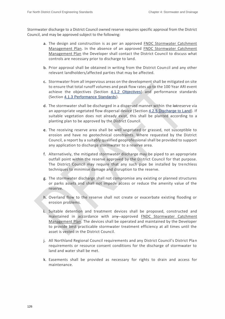
Far North District Council Engineering Standards Chapter 4: Stormwater and Drainage
126
Stormwater discharge to a District Council owned reserve requires specific approval from the District Council, and may be approved subject to the following:
The design and construction is as per an approved FNDC Stormwater Catchment Management Plan. In the absence of an approved FNDC Stormwater Catchment Management Plan the Developer shall contact the District Council to discuss what controls are necessary prior to discharge to land.
Prior approval shall be obtained in writing from the District Council and any other relevant landholders/affected parties that may be affected.
Stormwater from all impervious areas on the development shall be mitigated on site to ensure that total runoff volumes and peak flow rates up to the 100 Year ARI event achieve the objectives (Section 4.1.2 Objectives) and performance standards (Section 4.1.3 Performance Standards).
The stormwater shall be discharged in a dispersed manner within the lotreserve via an appropriate vegetated flow dispersal device (Section 4.2.5 Discharge to Land). If suitable vegetation does not already exist, this shall be planted according to a planting plan to be approved by the District Council.
The receiving reserve area shall be well vegetated or grassed, not susceptible to erosion and have no geotechnical constraints. Where requested by the District Council, a report by a suitably qualified geoprofessional shall be provided to support any application to discharge stormwater to a reserve area.
Alternatively, the mitigated stormwater discharge may be piped to an appropriate outfall point within the reserve approved by the District Council for that purpose. The District Council may require that any such pipe be installed by trenchless techniques to minimise damage and disruption to the reserve.
The stormwater discharge shall not compromise any existing or planned structures or parks assets and shall not impede access or reduce the amenity value of the reserve.
Overland flow to the reserve shall not create or exacerbate existing flooding or erosion problems.
Suitable detention and treatment devices shall be proposed, constructed and maintained in accordance with any approved FNDC Stormwater Catchment Management Plan. The devices shall be operated and maintained by the Developer to provide best practicable stormwater treatment efficiency at all times until the asset is vested in the District Council.
All Northland Regional Council requirements and any District Council’s District Pla n requirements or resource consent conditions for the discharge of stormwater to land and water shall be met.
Easements shall be provided as necessary for rights to drain and access for maintenance.

Far North District Council Engineering Standards Chapter 4: Stormwater and Drainage
127
4.2.4. Discharge to the Road Kerb
Stormwater discharge from lots to an approved road kerb connection detail is an acceptable solution for stormwater disposal only where a piped network or a natural watercourse is not available. Refer to drawing FNDCXX/XX for approved construction detail of stormwater connection to kerb and channel.
The use of kerbed roads for secondary (overland) flows is acceptable. All sites shall avoid discharges of primary stormwater flows onto roads where practicable.
4.2.5. Discharge to Land
Subject to the requirements of the Northland Regional Plan, discharge of stormwater to land is permitted provided that:
Flooding of low lying areas shall not be increased,
Outlets to low lying areas shall be provided or existing outlets retained,
Dispersal of concentrated flow from the development shall occur as soon as practicable and before any overland discharge to a neighbouring property occurs, and
An acceptable rate of dispersed discharge from collected flow at the boundary is < 2 litres/sec/m of run of discharge (i.e. from a flow dispersal swale).
Note: For example, for a 12 litre/sec discharge from attenuation or peak runoff shall provide a 6m linear length of dispersal swale.
4.2.6. Discharge to the Marine Environment
Any new outfall or physical changes to existing outfalls in the Coastal Marine Areas may require a Resource Consent from the Northland Regional Council.
The following requirements shall be satisfied when discharge of stormwater is proposed onto a beach or a District Council owned coastal reserve:
Regional Council resource consent shall be obtained (where required):
Compliance with the FNDC Stormwater Catchment Management Plan for the catchment (if any):
Compliance with the Northland Regional Plan, and
In addition
The foreshore yard of private property shall form well vegetated buffer areas,
Where landowners have retaining or erosion control walls on the coastal edge, the landward side of the wall shall be preferably used for wide dispersal of stormwater. A suitably qualified CPEng shall assess the potential impact on the retaining/erosion control structure, which may be caused by dispersing stormwater near the structure;
Where discharge through an outfall is the only alternative, the outfall shall be specifically designed to minimise beach erosion and adverse effects on beach amenity subject to specific approval of the District Council, and;

Far North District Council Engineering Standards Chapter 4: Stormwater and Drainage
128
Where stormwater discharges to tidal waters, the design shall assume a tide level of Mean High Water Spring (MHWS) plus a storm surge of 0.35m (0.15m barometric adjustment and 0.2m of surge).
4.3. Design
4.3.1. Capacity and Future System Expansion
As a minimum, stormwater systems shall convey both primary and secondary design flows from the upstream catchment(s) in its current developed state, for the design storms required by Section 4.3.9 Hydrological Design Criteria. In addition, the District Council may require the Developer to take account of increased flow from the potential development of the upstream catchment.
The District Council will provide information, where available, on the capacity of downstream reticulation. The Developer shall review the capacity to determine its adequacy. If there is inadequate capacity, the District Council may specify any required upgrades or alternative controls to manage capacity.
In the event that the District Council cannot provide information on the capacity of downstream reticulation, then the Developer shall undertake investigations, analysis, modelling or other work necessary to provide their estimate to the District Council of the capacity in the downstream reticulation. The District Council will review the Developer’s analysis and specify any required upgrades or alternative controls to manage capacity.
Data files and informative reports resulting from any modelling required to undertake the capacity analysis above shall be provided to the District Council for incorporation into their records.
4.3.2. Increases to Impervious Surface
Where any development increases impervious surface, the development shall be assessed in accordance with Section 4.1.2 Objectives and Section 4.1.3 Performance Standards to determine the requirements, if any, for water quality and quantity controls.
Design of new development or alteration to existing development, where the design will increase impervious surface, shall also comply with the Northland Regional Plan where it applies to the development.
4.3.3. Infiltration and Stability
Infiltration systems may be approved provided that a geotechnical investigation demonstrates that soils are suitable for soakage and the proposed device will not increase land instability.
Infiltration systems shall not be used in areas subject to medium or high instability hazard.
Attenuation systems proposed within areas designated as medium or high instability hazard shall protect against infiltration, e.g. by utilising sealed tanks or chambers, to avoid an increased stability hazard.
Attenuation and/or treatment systems shall not be located within low stability hazard land adjacent to an area of medium or high hazard without a specific engineering assessment of the impact of such a provision on the stability of the medium/high hazard land.
Note: instability hazard classifications may be shown on District Council’s Hazard Maps or may have been classified as such by a site specific Geotechnical Investigation.

Far North District Council Engineering Standards Chapter 4: Stormwater and Drainage
129
4.3.4. Pre-Consent Applications
4.3.4.1 Additional Information Requirements
In addition to the requirements in Section 1.5 Design, the following information shall be supplied with a resource consent application:
Proposed materials and systems for construction of proposed stormwater networks,
Proposed attenuation and/or water quality treatment system(s), including location(s), preliminary sizing and associated works (e.g. landscaping, road construction),
Copies of resource consents from the Northland Regional Council if required for works within a stream or river and any direct “discharge” to a waterway,
Copies of any correspondence and written approvals from private persons or Council departments in relation to the proposed stormwater system, and confirmation of how any conditions of those approvals will be met,
Demonstration (by drawings, calculations and reports) that the requirements of any permitted land use rules, which may be applicable to the proposed subdivision or land use development, can be achieved regarding stormwater service to lots, and
Outline Operations and Maintenance Requirements for any proposed storm water management systems, including water quality devices or structures.
4.3.4.2 Catchment Management Plans
Where a FNDC Stormwater Catchment Management Plan applies to the proposed development, the Developer shall identify the conditions that are considered to apply to the development, and then demonstrate how these will be met by the proposal.
The Developer shall account for catchment wide issues at the concept design stage, including the potential implications of future development upstream, and the cumulative effects of land development on water quality, flooding downstream and erosion. The Developer shall show how these potential effects will be addressed.
Developments within catchments with operative, consented Catchment Drainage or Catchment Management Plans (CDP or CMP) that comply with the requirements of these plans, will not require separate resource consents for stormwater diversion and discharge from Northland Regional Council provided that the development meets any applicable conditions set out in the referenced CDP/CMP.
Where an operative consented CDP/CMP is not in place, or the proposal is not consistent with an operative consented CDP/CMP, then:
The Developer shall obtain all necessary resource consents from Northland Regional Council (NRC) required for the work,
Where a consent is required for a facility that will vest in the District Counci l, then the NRC application shall be in the name of Far North District Council,
The Developer shall consult with the District Council to understand requirements regarding stormwater management (e.g. treatment and disposal), prior to submitting the NRC consent application, and regarding any draft Resource Consent conditions.

Far North District Council Engineering Standards Chapter 4: Stormwater and Drainage
130
The District Council will advise whether the area of a development is covered by a CDP/CMP, and conditions associated with it. The District Council may apply conditions/discharge constraints in addition to those imposed by NRC to safeguard elements of the District Council controlled downstream networks.

Far North District Council Engineering Standards Chapter 4: Stormwater and Drainage
131
4.3.5. Post-Consent Engineering Design Approval
4.3.5.1 General
All design shall be undertaken in accordance with the District Plan, Bylaws and Policies. In addition, design shall be consistent with national, regional and local statutory planning documents.
4.3.5.2 Content of Design Submission
In addition to the general requirements of Section 1.5.3 Detailed Design/Approval, the information submitted for Engineering Approval of stormwater design shall demonstrate (where applicable) the following:
That the design is consistent with the general requirements for the whole of the catchment,
That stormwater quality and quantity requirements are satisfied,
That pipeline design(s) provides the required level of service, including demonstration that non-surcharge and freeboard requirements have been met,
That secondary flow paths are available, and adequate for the design volumes. Flood heights shall be assessed and restrictions and/or easements required shall be identified,
Overland flow paths including the 1% AEP flood level, flow path boundaries and easement requirements clearly shown on drawings,
Minimum floor levels and flood hazard (depth, velocity) for residences and escape routes within 1% AEP flood inundation areas on the site are available and shown on the drawings,
Scour protection has been designed for the estimated flows and velocities at outlets and in channels,
That the proposed stormwater system satisfies the objectives (Section 4.1.2
Objectives) and performance standards (Section 4.1.3 Performance Standards) in all other respects.
The design submission shall demonstrate that any identified off-site effects have been sufficiently mitigated. Off-site effects shall include changes to:
Flow peaks (where approved) and frequency patterns,
Flood water levels, flood plain storage volumes,
Water quality,
Erosion of waterways, and
Discharge of stormwater on downstream properties.
For constructed ponds and wetlands, a complete set of drawings and design calculations shall be submitted for approval as well as a geotechnical report addressing general ground stability of the pond under all operational conditions. The necessity for lining to prevent piping shall be assessed and specific liner design may be required.

Far North District Council Engineering Standards Chapter 4: Stormwater and Drainage
132
Operation and maintenance manuals for any water quantity and/or quality control structures shall be provided in finalised form for approval with the design.
Design that deviates from the standard solutions shall be carried out and certified by an IQP, who is working within their assessed competencies in accordance with the requirements of Section 1.5.1.3
The Role of the IQP. The IQP shall identify the design standards used and certify that the design complies with the referenced standards.
Any approvals from the District Council for alternative solutions shall be provided with the design documentation.
4.3.6. Design Life
Stormwater systems to be vested in the District Council shall have an asset life of at least 100 years.
Where components of the stormwater system (such as stormwater detention and treatment devices) require earlier renovation or replacement in order to provide an asset life of 100 years for the system, then this requires the District Council’s specific approval. The Developer shall document the asset renewal requirements in the Operations and Maintenance Requirements, which shall be provided for design approval.
The asset life of private stormwater systems shall be at least 50 years in accordance with the NZ Building Code.
4.3.7. Approved Materials
Refer to FNDC Approved Materials List - Wastewater and Stormwater.
The use of material not described in the FNDC Approved Materials List - Wastewater and Stormwater shall be considered Alternative Designs, refer Section 1.5.1.2 Alternative Designs.
Table 4-1: Pipe Material and Class for Stormwater Drainage
Material Standard Class (min) Notes
RCRRJ (Reinforced Concrete Rubber Ring Joint)
AS/NZS 4058:2007
2 Class for shallow pipes or particular loading to be by
Specific Design
uPVC
AS/NZS 1260:2017
SN8 or SN 16, as required by the District Council
Concrete protection/capping required for road crossings with cover less than 900mm
AS/NZS 1254:2010
SN8, as required by the District Council
Concrete protection/capping required for road crossings with cover less than 900mm
PE AS/NZS 5065:2005
SN16 Black Outer, White or Brown Inner lining. Internal bead formed by welding shall be removed

Far North District Council Engineering Standards Chapter 4: Stormwater and Drainage
133
PP
(e.g. ‘StormBoss’ twin wall pipe)
AS/NZS 5065:2005
SN 16
Subject to specific approval. Shall be shown to be capable of withstanding a jetting resistance to 4000psi (280 bar) without damage
Concrete protection/capping required for road crossings with cover less than 900mm

Far North District Council Engineering Standards Chapter 4: Stormwater and Drainage
134
4.3.8. System Design
4.3.8.1 General
Stormwater systems shall be considered as the total system protecting people, land, infrastructure and the receiving environment. A stormwater system consists of:
A primary system designed to accommodate a specified design rainfall event appropriate for the Land Use Classification, and,
A secondary system to ensure the effects of stormwater runoff from events that exceed the capacity of the primary system are managed, including when there are blockages in the primary system.
The design shall be in accordance with Table 4-2 below unless the approved Catchment Management Plan or District Plan requires different values.

Far North District Council Engineering Standards Chapter 4: Stormwater and Drainage
135
Table 4-2: Minimum Design Summary
Criteria Design Parameter When Required
Design calculations Rational method up to 8ha. For catchments greater than 8ha, by acceptable hydrological or hydraulic model.
Always.
Runoff coefficients
Pre-development runoff coefficients shall be based on the existing Land Use Classification.
Post-development runoff coefficients shall be based on the Land Use Classification after development. Refer Table 4-4
Always.
Design Rainfall Refer to Design Rainfall (Section 4.3.9.4 Design Rainfall and Section 4.3.9.5 Design Storm).
Current rainfall (i.e. not climate change adjusted) shall be used for the following:
• Sizing temporary works where climate change is not relevant.
• Determining pre-development stormwater runoff flows and volumes for use in combination with calculated post development flows to determine stormwater treatment (quantity and quality) requirements
Climate change adjusted rainfall shall be used for the following:
• Determining post-development stormwater runoff flows and volumes for stormwater infrastructure design.
Time of concentration
Calculated in accordance with Section 4.3.9.4 Design Rainfall. Always.
Flood Control
(100 year ARI event)
Mitigation required, limiting the post-development (NIWA RCP8.5) 10- and 100-year ARI event flow rates for the duration of the storm to 80% of the pre-development 10- and 100-year ARI event flow rates through controlled mitigations and multistage outlets or devices that reduce volume of runoff.
1. Discharge to natural flow and secondary flow path.
2. Direct nuisance to other property and people.
3. Discharge to council stormwater and roading network.
4. Where identified downstream flooding (or risk of) exists .19
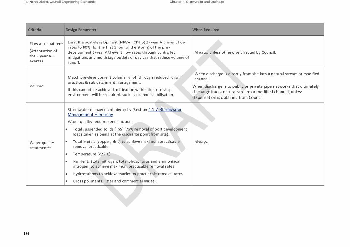
Far North District Council Engineering Standards Chapter 4: Stormwater and Drainage
136
Criteria Design Parameter When Required
Flow attenuation20
(Attenuation of the 2 year ARI events)
Limit the post-development (NIWA RCP8.5) 2- year ARI event flow rates to 80% (for the first 1hour of the storm) of the pre-development 2-year ARI event flow rates through controlled mitigations and multistage outlets or devices that reduce volume of runoff.
Always, unless otherwise directed by Council.
Volume
Match pre-development volume runoff through reduced runoff practices & sub catchment management.
If this cannot be achieved, mitigation within the receiving environment will be required, such as channel stabilisation.
When discharge is directly from site into a natural stream or modified channel.
When discharge is to public or private pipe networks that ultimately discharge into a natural stream or modified channel, unless dispensation is obtained from Council.
Water quality treatment21
Stormwater management hierarchy (Section 4.1.7 Stormwater
Management Hierarchy)
Water quality requirements include:
• Total suspended solids (TSS) (75% removal of post development loads taken as being at the discharge point from site).
• Total Metals (copper, zinc) to achieve maximum practicable removal practicable.
• Temperature (<25°C)
• Nutrients (total nitrogen, total phosphorus and ammoniacal nitrogen) to achieve maximum practicable removal rates.
• Hydrocarbons to achieve maximum practicable removal rates
• Gross pollutants (litter and commercial waste).
Always.

Far North District Council Engineering Standards Chapter 4: Stormwater and Drainage
137
Criteria Design Parameter When Required
Water quality (treatment) volume
1/3 of 2 year 24-hour ARI rainfall depth with climate change used to calculate Water Quality Volume (WQV)
Always.
If extended detention is required to protect natural receiving environments (refer below), half of the calculated WQV can be included within the Extended Detention Volume22 (EDV). Hence the water quality volume provided as permanent water volume can be reduced by 50%.23
Extended Volume
(EDV) Detention
When discharge is into a natural stream or modified channel.
EDV is assessed by multiplying the Water Quality Storm by 1.2, refer above24.
That volume is then stored and released over a 24-hour period.
Primary25 and Secondary System Level of Service
As per Table 4-3 Secondary overflow as per Section 4.1.3
Stormwater Management Hierarchy). Always.
Minimum Floor Levels
Freeboard requirements (Section 4.3.10.7 Freeboard
Requirements) Always.
Refer Flood Hazard Areas in the District Plan and any known downstream restrictions causing flooding.
Retention is encouraged alongside EDV but is generally located on private property
Unless alternative criteria are provided within a relevant Resource Consent.
Refer Auckland Regional Council TP10 or equivalent document for detail of Extended Detention design.
Refer Section 5.4.1 of Auckland Regional Council TP10
Based on 1/3 of the 2 year 24 hour rainfall depth with climate change included.
The primary system shall be designed to ensure capacity to accommodate the peak flows, without surcharge

Far North District Council Engineering Standards Chapter 4: Stormwater and Drainage
138
The following shall be considered and where appropriate included in the design
Quality and quantity requirements of any discharge,
How the roading stormwater design is integrated into the overall stormwater system,
The type and class of material proposed to be used,
System layouts and alignments including route selection, topographical and environmental aspects, easements, clearances from underground services and structures, provision for future extensions, location of secondary flow paths,
Hydraulic adequacy Section 4.3.10 Hydraulic Design, and
Where applicable, location of service connections.
The following documents provide guidance in the design of pipes, culverts, detention and treatment devices and open channel hydraulics:
The NZ Building Code compliance document Clause E1 – Surface water (NZBC Clause E1)
Auckland Council GD01 Stormwater Water Management Devices Guidelines
Note: NZBC Clause E1 provides guidance on runoff coefficients, which are not acceptable for the design of public infrastructure under the ES.
For catchments less than 8 hectare, the Rational Method can be used to calculate surface water runoff.
For larger catchments, or where significant storage elements (such as stormwater detention and treatment devices) are incorporated, surface water runoff should be determined using an appropriate hydrological or hydraulic computerised model.
A complete copy of the model shall be provided to the District Council at no charge. All underlying assumptions (such as losses, time of concentration, and catchment areas) shall be clearly stated so that a full check of calculations is practicable.
4.3.8.2 Primary System Design Requirements
The land drainage system shall be capable of serving the entire catchment upstream of the subdivision (Section 4.3.1 Capacity and Future System Expansion) and shall mitigate effects that the development may have on downstream waterways and adjoining areas. It shall be designed within the terms of any approved Catchment Management Plan.
The runoff characteristics of upstream areas shall be based on the development that is compatible with the zoning of the land at the time of engineering design.
Each lot shall have a single stormwater connection, which shall be capable of serving the whole of the lot. Where connection to the District Council system is utilised the connection shall be able to service at least the whole building and developed area available on the lot.
Concentrated stormwater runoff shall not be permitted to discharge across footpaths, berms or from or to adjacent properties. Sheet flow from upstream lots or sub-catchments shall be intercepted by either the primary drainage system or the overland flow paths wherever such sheet flow may create a nuisance to downstream lots or present a danger to people by way of depth and velocity.
Where further development upstream of the one under consideration is provided for in the District Plan, the stormwater system shall be extended in accordance with Section 4.3.1 Capacity and Future System Expansion to the upper limits of the development.

Far North District Council Engineering Standards Chapter 4: Stormwater and Drainage
139
The preferred means of stormwater disposal shall be to adopt stormwater control measures that retain the pre-development catchment characteristics for ground soakage and runoff.
Where soakage, transpiration and reuse cannot fully mitigate an increase in stormwater from a development, detention shall be provided to restrict the peak runoff from the site subject to the provisions of Table 4-2.
For the purposes of determining the increase in flow between pre and post - development reference shall be made to Table 4-2 and Section 4.3.9 Hydrological Design Criteria.
The treatment of stormwater in ponds or wetlands is permitted provided that:
The pond complies with the requirements of the Northland Regional Plan,
Stormwater pond detention areas shall be contained within the legal boundaries of a drainage reserve,
The pond shall not be included in local purpose reserves without specific prior approval from the District Council, and
The ponds or wetland shall be designed in accordance with Auckland Council Guideline Document 2015/004 and 2017/001 with the proviso that where the requirements of Auckland Council Guidelines are not practicable, application may be made to the District Council to vary these requirements.
(Refer to Section 4.3.20.8 Constructed Ponds and Wetlands for additional requirements for constructed ponds and wetlands).
Under no circumstances shall stormwater be led to or be permitted to enter a wastewater system.
Development (including any land modification) shall ensure that surface water runoff is appropriately managed in accordance with the Stormwater Management Hierarchy in Section 4.1.7 Stormwater
Management Hierarchy.
4.3.8.2.2. Stormwater Pumping
The District Council considers that pumping of stormwater is rarely a practicable option because of the need for continuity of power supply and a very conservative approach to pumping design.
Applications for pumping stormwater shall demonstrate, with supporting data, that all practicable alternatives have been investigated, and provide sufficient risk mitigation for pump malfunction and power outages.
4.3.8.2.3. Availability/Capacity of the Existing District Council Stormwater Reticulation
Where a development will result in an increase in stormwater flow, Developers shall investigate the availability of capacity in the existing District Council stormwater system to ensure that the proposed additional flows can be accommodated for the events in Table 4-4.
The District Council may require additional capacity to be provided in the existing or proposed system if either system is critical for the long-term planning of growth. Additional capacity in the proposed system (if required) shall be at the Developer’s cost (see also Section 4.3.8.4 District Council Design Input).
4.3.8.3 Secondary System Design Requirements – Overland Flow
Secondary or overland flow paths may be under public control by reserve or easement
Secondary systems shall consist of overland flow paths to manage excess runoff during events exceeding the capacity of the primary system and occasions when the primary system fails
The design shall include a full analysis of the overland flow paths. This shall include preparation of plans, long sections and cross sections showing design water levels for a 1% AEP (+20%) storm. Where the
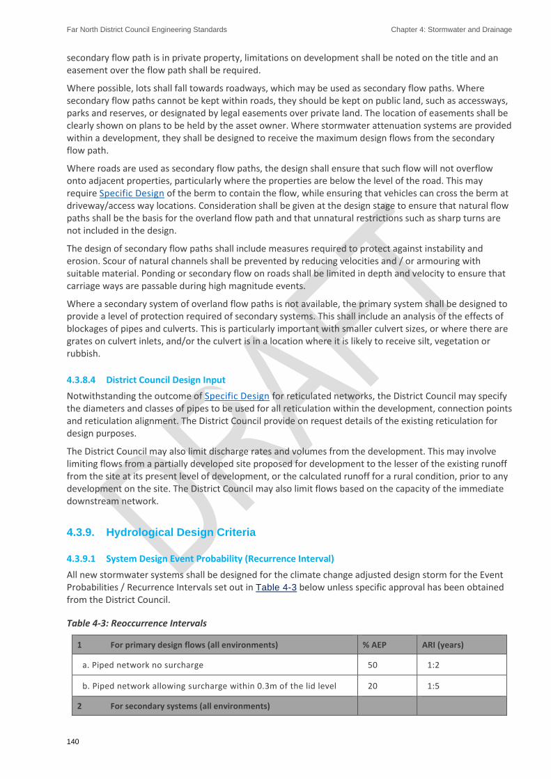
Far North District Council Engineering Standards Chapter 4: Stormwater and Drainage
140
secondary flow path is in private property, limitations on development shall be noted on the title and an easement over the flow path shall be required.
Where possible, lots shall fall towards roadways, which may be used as secondary flow paths. Where secondary flow paths cannot be kept within roads, they should be kept on public land, such as accessways, parks and reserves, or designated by legal easements over private land. The location of easements shall be clearly shown on plans to be held by the asset owner. Where stormwater attenuation systems are provided within a development, they shall be designed to receive the maximum design flows from the secondary flow path.
Where roads are used as secondary flow paths, the design shall ensure that such flow will not overflow onto adjacent properties, particularly where the properties are below the level of the road. This may require Specific Design of the berm to contain the flow, while ensuring that vehicles can cross the berm at driveway/access way locations. Consideration shall be given at the design stage to ensure that natural flow paths shall be the basis for the overland flow path and that unnatural restrictions such as sharp turns are not included in the design.
The design of secondary flow paths shall include measures required to protect against instability and erosion. Scour of natural channels shall be prevented by reducing velocities and / or armouring with suitable material. Ponding or secondary flow on roads shall be limited in depth and velocity to ensure that carriage ways are passable during high magnitude events.
Where a secondary system of overland flow paths is not available, the primary system shall be designed to provide a level of protection required of secondary systems. This shall include an analysis of the effects of blockages of pipes and culverts. This is particularly important with smaller culvert sizes, or where there are grates on culvert inlets, and/or the culvert is in a location where it is likely to receive silt, vegetation or rubbish.
4.3.8.4 District Council Design Input
Notwithstanding the outcome of Specific Design for reticulated networks, the District Council may specify the diameters and classes of pipes to be used for all reticulation within the development, connection points and reticulation alignment. The District Council provide on request details of the existing reticulation for design purposes.
The District Council may also limit discharge rates and volumes from the development. This may involve limiting flows from a partially developed site proposed for development to the lesser of the existing runoff from the site at its present level of development, or the calculated runoff for a rural condition, prior to any development on the site. The District Council may also limit flows based on the capacity of the immediate downstream network.
4.3.9. Hydrological Design Criteria
4.3.9.1 System Design Event Probability (Recurrence Interval)
All new stormwater systems shall be designed for the climate change adjusted design storm for the Event Probabilities / Recurrence Intervals set out in Table 4-3 below unless specific approval has been obtained from the District Council.
Table 4-3: Reoccurrence Intervals
1 For primary design flows (all environments) % AEP ARI (years)
a. Piped network no surcharge 50 1:2
b. Piped network allowing surcharge within 0.3m of the lid level 20 1:5
2 For secondary systems (all environments)

Far North District Council Engineering Standards Chapter 4: Stormwater and Drainage
141
c. Overland flowpaths 1 1:100
3 For flood protection (all environments)
d. All areas 1 1:100
The Climate Change allowance shall be an addition of 20% to NIWA rainfall intensity data for the design event.
4.3.9.2 Stormwater Flow Estimate
Rainfall runoff curves are used to describe rainfall losses. The curves used in Auckland Regional Council TP108 GD01 and other methods were developed by the US National Resource Conservation Service, previously known as Soil Conservation Service (SCS). Curve numbers (CN) were determined based on the hydrological soil group, cover type, soil treatment, hydrological condition and antecedent ground condition.
Values from the summary sheets in USDA Soil Conservation Service TR-55 and Auckland Regional Council TP108 have been adopted for typical Northland soils encountered in the Far North District. Table 4-4 below sets out the typical values to be applied. For more detailed information refer to the original tables in USDA Soil Conservation Service TR-55 or Table 2-2 of Auckland Regional Council TP108.
Runoff Coefficients (C) represents the proportion of rainfall resulting in physical runoff for calculation of flow. The values given in E1 of the NZ Building Code are considered low for Northland conditions during significant rainfall events. The District Council has adopted figures developed from the formula C= CN/ (200-CN) from Auckland Regional Council TP108. These values are listed side by side in Table 4-4 below.
The (Rational Method) runoff coefficients in Table 4-4 are for peak flow rate and may be modified for slope as discussed in NZ Building Code Clause E1.
The variability of soils within the Far North District and wider Northland, are borne out by changes in runoff characteristics in addition to that caused by vegetation cover. The four hydrologic soil groups are:
D Very low permeability such as clay (e.g. Northland Allochthon/Onerahi Chaos)
C Low permeability such as loam (e.g. Maunu and Glenbervie volcanics)
B Medium permeability, coastal windblown sands (e.g. Ruakaka and Waipu coastal sands)
A High permeability such as fractured rock and deeply bedded scoria deposits.
Soil type A is not usually encountered at surface levels and typically is only used for discharge to ground solutions by deep infiltration. Soil type A should not be used for the calculation of surface runoff.
Note: Auckland Regional Council TP108 soil classification table contains an error in that the soil class A descriptor is missing, and the table relates to soil classes B, C and D.
Table 4-4: Curve Numbers and C Values for Typical Far North District Conditions (CN - C) TP108????
Land Use % impervious Type B soils Type C soils Type D soils
Open space (lawns, parks etc.)
Fair condition (grass cover 50-75%) 69 - 0.53 79 - 0.65 84 - 0.72
Good condition (grass cover >75%) 61 - 0.44 74 - 0.59 80 - 0.67
Impervious areas
Paved parking lots, roofs, driveways, curbs, channels etc. (excluding right-of-way)
98 - 0.96 98 - 0.96 98 - 0.96

Far North District Council Engineering Standards Chapter 4: Stormwater and Drainage
142
Land Use % impervious Type B soils Type C soils Type D soils
Roads and streets
Paved: open ditches (incl right-of-way) 89 - 0.80 92 - 0.85 93 - 0.87
Unsealed/Gravel (incl right-of-way, accessway & parking areas)
85 - 0.74 89 - 0.80 91 - 0.83
Urban development
Commercial and business 85 92 - 0.85 94 - 0.89 95 - 0.90
Industrial 72 88 - 0.79 91 - 0.83 93 - 0.87
Landscaped 0 70 75 80
Residential by average lot size
500m² or less 65 85 - 0.74 90 - 0.82 92 - 0.85
1000m² 40 75 - 0.60 83 - 0.71 87 - 0.77
2000m² 25 70 - 0.54 80 - 0.67 85 - 0.74
4000m² 20 68 - 0.52 79 - 0.65 84 - 0.72
10,000m² (1 ha) 10 65 - 0.48 77 - 0.63 82 - 0.69
Rural development
Pasture, grassland (m²) 61 - 0.44 74 - 0.59 80 - 0.67
Grass and bush 48 - 0.32 65 - 0.48 73 - 0.57
Trees and grass combination (orchards) 58 - 0.41 72 - 0.56 79 - 0.65
Forest 55 - 0.38 70 - 0.54 77 - 0.63
4.3.9.2.1. Catchments Larger Than 8ha
For larger catchments (greater than 8ha), or where significant storage elements are incorporated, surface water runoff should be determined using an acceptable hydrological or hydraulic model.
FNDC Approved Materials List - Wastewater and Stormwater includes a list of acceptable hydraulic modelling software. Alternative modelling methods require the District Council’s specific approval.
4.3.9.3 Time of Concentration
The time of concentration shall be determined as the ‘time of entry’ plus the ‘time of flow’ from the furthest point of the whole catchment to the point of discharge.
Time of entry to the system shall be calculated from Figure 4-1 or an equivalent published graph or the formula from which it was derived.
Time of flow can be calculated from the velocity in pipes and channels.
Note: Since the time of concentration is not known initially, an iterative solution is necessary with time of concentration recalculated from the catchment flow calculation.

Far North District Council Engineering Standards Chapter 4: Stormwater and Drainage
143
Figure 4-1: Overland Flow Graph

Far North District Council Engineering Standards Chapter 4: Stormwater and Drainage
144
4.3.9.4 Design Rainfall
Acceptable sources for rainfall data for design within the Far North District are:
Rainfall depth data from NIWA High Intensity Rainfall Data System. In addition (where appropriate) other acceptable alternatives include analysis of a specific site based on information provided by verified research studies of particular soil or site conditions.
The current rainfall pattern (not adjusted for climate change) shall be used to determine detention requirements for infill developments where existing connections generate ‘existing use rights’ and also for temporary works where climate change rainfall is not relevant.
4.3.9.5 Design Storm
For analysis of rainfall events either the Modified Rational Method (variable duration, uniform profile), or a USDA Soil Conservation Service TR-55 type 1A storm profile (fixed duration, variable profile) are acceptable for determining peak flow and runoff volumes, subject to the criteria set out below.
The minimum duration of the design storm for the pre-developed flow consideration using Modified Rational Method shall be 60 minutes (all Environments). The post-developed design shall be tested for critical duration taking into account the effects of attenuation and detention on the discharge.
Note: This critical duration is unlikely to be the same as that used for the pre-development assessment.
The use of the Auckland Regional Council TP108 profile for estimation of pre-development peak runoff in the Far North District is not acceptable.
4.3.10. Hydraulic Design
4.3.10.1 Energy Loss through Structure
Energy loss is expressed as velocity head:
Energy loss: He = kV2/2g
where k is the entrance loss coefficient and V is velocity.
The entrance loss coefficient table and energy loss coefficient graph in NZ Building Code E1 provide k values for flow through inlets and access chambers respectively.
For bends, see Error! Reference source not found..
4.3.10.2 Determination of Water Surface Profiles
Stormwater systems shall be designed by calculating or computer modelling backwater profiles from an appropriate outfall water level.
On steep gradients both inlet control and hydraulic grade line analysis shall be used and the more severe relevant condition adopted for design purposes.
For pipe networks at manholes and other nodes, water levels computed at design flow shall not exceed finished ground level while allowing existing and future connections to function satisfactorily.

Far North District Council Engineering Standards Chapter 4: Stormwater and Drainage
145
4.3.10.3 Minimum Pipe Diameters
The following minimum pipe diameters shall apply:
Public stormwater main: 300mm.
Private / Lateral connection:100mm.
In no circumstances shall the pipe size be reduced on any downstream section.
4.3.10.4 Minimum Gradients and Flow Velocities in Pipes
Pipe gradients should be at a grade that prevents silt deposition and is practical to construct. The minimum velocity should be at least 0.6m/s at a flow of half the 2-year ARI design flow.
For velocities greater than 3.0m/s Specific Design to resist pipe erosion is required.
Details shall be provided by a suitably qualified person to demonstrate compliance with these design conditions.
Note: Pipes laid to minimum grades will NOT be accepted in ground liable to settlement.
4.3.10.5 Minimum Pipe Roughness
The minimum ‘Colebrook-White’ roughness coefficient shall be 0.06 for design of both Reinforced Concrete and uPVC pipes.
Alternatively, the minimum Manning’s roughness coefficient shall be 0.011 for design of both Reinforced Concrete and uPVC pipes.
4.3.10.6 Pipe Surcharge
Pipelines shall not surcharge during the 50% AEP (2-year ARI) in any part of the design network.
Surcharge of pipelines may occur during the 20% AEP (5-year ARI) but shall be limited to within 0.3m below any structure lid. It is assumed that the lid is at or near finished ground level.
4.3.10.7 Freeboard Requirements
Freeboard above the secondary flow level is required to cater for inaccuracies in flow estimation and practicable blockage/failure of the primary system
The minimum freeboard above the calculated 1% AEP storm (flood protection level) shall be:
0.5m for habitable building floors, and,
0.3m for commercial and industrial buildings,
Unless specific assessment demonstrates that an increased freeboard is appropriate.
Minimum floor levels shall be identified for all lots within the area of the site inundated during the 1% AEP flood event. This requires assessment of flooding caused by different sources including:
Rivers,
Tides,
Elevated groundwater, and
Surface water ponding.
Minimum floor levels in tidal areas shall be set taking into account storm surge, tsunami hazards, climate change and sea level rise.

Far North District Council Engineering Standards Chapter 4: Stormwater and Drainage
146
Escape routes from properties during flooding shall be above the flood protection level. Where this is not practicable (e.g. the road/access forms the secondary flow path), the depth and velocity of flow shall be such that the escape routes remain passable to the applicable traffic (e.g. vehicles on carriageways, pedestrians on footpaths). This information shall be indicated on the drawings.
The minimum floor level as a permitted activity under the District Plan for Coastal Areas is RL 2.5m (One Tree Point datum 1964). However, specific assessment shall be carried out for all sites to determine an actual floor level dependant on local conditions. Specific assessment should include reference to the NRC Regional Policy Statement and NRC Coastal Flood Hazard Zones for Select Northland Sites 2017 update. Wave run-up shall be provided for.
4.3.11. Watercourses
4.3.11.1 General Requirements
Natural watercourses shall be retained.
The extent of stream drainage work shall be designed to achieve a satisfactory solution recognising:
Community flood protection,
Bank stability,
The retention of the natural topography and ecological values,
Maintenance requirements such as access,
Hydraulic and safety considerations, and
Downstream effects of the work
4.3.11.2 Constructed Watercourses
Existing constructed watercourses (open drains) may be piped if there are valid engineering or design considerations, ecological impacts have been considered and N orthland Regional Council approval is obtained where necessary. The engineering design drawings should be annotated accordingly.
Where waterways are incorporated in the stormwater system, they must be located within a Drainage Reserve (Section 4.3.11.5 Drainage Reserves) of sufficient width to contain the full design storm flow from a 100 Year ARI event with a minimum freeboard as per Section 4.3.10.7 Freeboard Requirements.
Planted riparian margins shall be provided each side of the waterway to maximise bank stability and public safety
All channel infrastructure shall include protection against scour and erosion of the stream banks and stream bed using biotechnical treatments where feasible.
If the constructed watercourse i s l o c a t e d w i t h i n private property, a g r e em e n t m u s t b e in place to specify responsibility for maintenance. At a minimum the constructed watercourse shall be protected by an easement and constructed in compliance with Sheet 36, or an approved equivalent.
4.3.11.3 Natural Open Stream Systems
Where natural open stream systems or formed channels shall be incorporated in the stormwater drainage system they shall be located within a Drainage Reserve (Section 4.3.11.5 Drainage Reserves) of sufficient width to contain the overall system design storm flow.
It shall be demonstrated that the open drain system:
Can be used where it is in keeping with the existing drainage network,
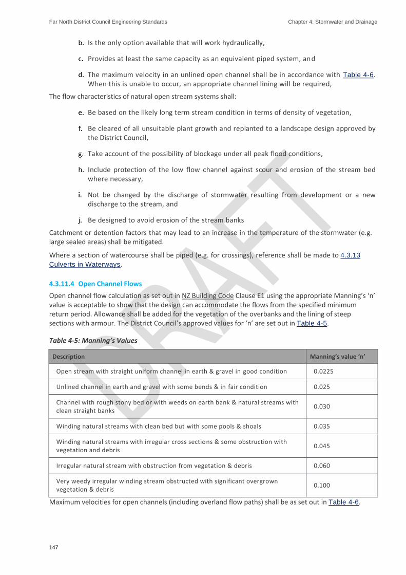
Far North District Council Engineering Standards Chapter 4: Stormwater and Drainage
147
Is the only option available that will work hydraulically,
Provides at least the same capacity as an equivalent piped system, and
The maximum velocity in an unlined open channel shall be in accordance with Table 4-6. When this is unable to occur, an appropriate channel lining will be required,
The flow characteristics of natural open stream systems shall:
Be based on the likely long term stream condition in terms of density of vegetation,
Be cleared of all unsuitable plant growth and replanted to a landscape design approved by the District Council,
Take account of the possibility of blockage under all peak flood conditions,
Include protection of the low flow channel against scour and erosion of the stream bed where necessary,
Not be changed by the discharge of stormwater resulting from development or a new discharge to the stream, and
Be designed to avoid erosion of the stream banks
Catchment or detention factors that may lead to an increase in the temperature of the stormwater (e.g. large sealed areas) shall be mitigated.
Where a section of watercourse shall be piped (e.g. for crossings), reference shall be made to 4.3.13
Culverts in Waterways.
4.3.11.4 Open Channel Flows
Open channel flow calculation as set out in NZ Building Code Clause E1 using the appropriate Manning’s ‘n’ value is acceptable to show that the design can accommodate the flows from the specified minimum return period. Allowance shall be added for the vegetation of the overbanks and the lining of steep sections with armour. The District Council’s approved values for ‘n’ are set out in Table 4-5.
Table 4-5: Manning’s Values
Description Manning’s value ‘n’
Open stream with straight uniform channel in earth & gravel in good condition 0.0225
Unlined channel in earth and gravel with some bends & in fair condition 0.025
Channel with rough stony bed or with weeds on earth bank & natural streams with clean straight banks
0.030
Winding natural streams with clean bed but with some pools & shoals 0.035
Winding natural streams with irregular cross sections & some obstruction with vegetation and debris
0.045
Irregular natural stream with obstruction from vegetation & debris 0.060
Very weedy irregular winding stream obstructed with significant overgrown vegetation & debris
0.100
Maximum velocities for open channels (including overland flow paths) shall be as set out in Table 4-6.

Far North District Council Engineering Standards Chapter 4: Stormwater and Drainage
148
Table 4-6: Maximum Velocities in Channels
Description Max velocity (m/s)
Earth channels – no bed vegetation 0.6
Fully vegetated channels (e.g. swales) 1.0
Rock spall lined channels 2.0
Fine sand, colloidal 0.4
Sany loam, noncolloidal 0.5
Silt loam, non collodial 0.6
Alluvial silts, noncollodial 0.6
Ordinary firm loam 0.8
Volcanic ash 0.8
Stiff clay, very colloidial 1.1
Alluvial silts, colloidal 1.1
Shales and hardpans 1.8
Fine gravel 0.8
Graded loam to cobbles, noncolloidal 1.1
Graded silts to cobbles, colloidal 1.2
Coarse gravel, noncolloidal 1.2
Cobbles and shingles 1.5
4.3.11.5 Drainage Reserves
Drainage Reserves shall have maximum and minimum slopes of 1:5 and 1:50 respectively. When access for maintenance is required, access provisions shall also include:
A 4m wide berm that is accessible by an 8.2 tonne axle weight vehicle for its entire length and provision for turning (if applicable), and
Access from public carriageways.
To encourage the best use of the open stream systems the drainage reserve shall, where practicable, be linked with other reserves and open spaces to accommodate off road pedestrian and cycle access. Access points for public use and maintenance shall be provided at regular intervals along the system together with footpath and pedestrian bridges, as may be required in the resource consent conditions.
4.3.12. Outlets and Inlets
4.3.12.1 General
All culvert and pipeline inlets and outlets shall be provided with adequate wing walls, headwalls, aprons and scour protection for erosion control, fill retention around the pipeline, and pipeline support. Adequate energy dissipation shall be provided and consideration should be given to fish passage where appropriate.

Far North District Council Engineering Standards Chapter 4: Stormwater and Drainage
149
Open-ended manholes to serve as high flow inlets shall have grates or scruffy domes installed.
Approved structures for use at the inlets and outlets of pipelines are shown on Sheet 35. Non-approved structures shall be considered Alternative Designs and, as such, Section 1.5.1.2 Alternative Designs shall be followed.
With respect to health and safety, all inlets to the stormwater network greater than 375mm diameter shall be fitted with a safety grille. The inlet grille shall be specifically designed and requires Council approval. The grille shall be vertical and have a clear opening of 100mm between bars. Note that grilles are not required on manholes and will only be required at the inlet to a culvert in special circumstances as required by the District Council.
Where outlets or inlets are located on or near natural waterways their appearance in the riparian landscape and likely effect on in-stream values must be considered. Outlet structures shall be constructed so as not to provide any restriction to the flows in the watercourse. Methods could include cutting off the pipe end at an oblique angel to match slope, constructing a headwall from local materials such as rock or boulders, planting close to the structure and locating outlets well back from the water’s edge.
4.3.12.2 Outlet Design
Outlet structures shall be designed in general accordance with Auckland Council TR2013/018, or Auckland Regional Council TP10, whichever is most relevant to the outfall, and shall not restrict the flows in the receiving watercourse.
Outlet design shall ensure non-scouring velocities at the point of discharge. Acceptable outlet velocities will depend on soil conditions, but should not exceed 2m/s without specific provision for energy dissipation and velocity reduction (designs must clearly illustrate this requirement).
Where the discharge to a watercourse represents more than 10% of the watercourse flow rate for an equivalent event, adequate energy dissipation must be provided.
Outlet designs shall incorporate the following:
Alignment with a Stormwater Catchment Management Plan (where available),
Fit for purpose over the design life,
River level and flows,
River bank erosion protection to 0.5m below minimum river level,
Extending outlet works below the river surface,
Developing a consistent design criteria for outlet works taking into account public safety requirements, natural character of the surrounds, amenity and aesthetics of the river,
Appropriate planting of indigenous species where required, and
Retaining and enhancing remnant areas of indigenous riverbank vegetation.
4.3.12.3 Inlet Design
The inlet design shall take into account particular circumstances at each site using the following evaluation and guidelines:
Direction of upstream flow,
Signs of erosion both lateral and down cutting,
Height of headwall,

Far North District Council Engineering Standards Chapter 4: Stormwater and Drainage
150
Need for overland flow path,
General aesthetics,
Hydraulic efficiency, and
Fish passage
The selection of a suitable location may influence the pipe alignment. A minimum clearance of 1.0m shall be provided clear of the opening around any inlet structure that may allow entry for maintenance and rescue equipment. The District Council may determine other specific requirements subject to individual site characteristics.
Screens are required where flow from open drains, detention and treatment systems enters into a piped network (excluding culverts).
All screens shall be constructed from hot-dipped galvanised steel and the horizontal gap shall not exceed 100mm. Specific Design is required to meet the requirements of the site and public safety issues including the provision of access to the inlet structure for maintenance and cleaning of blockages. Screens shall be designed to be self-cleansing and to withstand the loads imposed by debris blocking the inlet and the resulting hydraulic head. Where the consequences of a screen blockage are likely to be severe, a backup overflow system that allows runoff to enter the pipe or a clearly defined secondary flowpath shall be provided.
4.3.13. Culverts in Waterways
4.3.13.1 General
Refer to Section 3.2.20 Bridges, Culverts and Other Structures for culvert design requirements in respect of roading and access-ways.
Culverts in waterways shall be designed for the applicable post development design event in Table 4-7. In designing culverts the effects of inlet and outlet tailwater controls shall be considered. All culverts shall be provided with adequate wingwalls, headwalls, aprons, scour protection, removable debris traps or pits to prevent scouring or blocking.
When boxes/pipes/arches or culverts are placed side-by-side to create a width of greater than 6.0m, the culvert is defined as a bridge culvert – these shall be designed in accordance with the Section 3.2.20
Bridges, Culverts and Other Structures and the NZ Fish Passage Guideline.
Consideration shall be given to design details that allow appropriate conveyance of water flow and unimpeded fish passage. The design shall minimise upstream flooding, blockages and scouring.
If culvert design results in an upstream ponding depth of more than 3.0 m it is considered a ‘dam’, and subject to the Building Act.
It is usual for resource consents conditions to require that culvert construction in waterways be accompanied by sediment control measures as set out in an Erosion and Sediment Control Plan. Refer to the Northland Regional Plan.
4.3.13.2 Catchment Parameters
The following information shall be provided for culvert crossing design:
Catchment area to drain through the culvert,
Topography,
Land use description and potential for land use change,
Maximum channel and catchment length,

Far North District Council Engineering Standards Chapter 4: Stormwater and Drainage
151
Change in elevation over maximum channel length,
Catchment slope and orientation,
Average slope over maximum channel length,
Existing channels both upstream and downstream, and
Any specific requirements from an applicable Catchment Management Plan.
4.3.13.3 Culvert Design Event Probability (Recurrence Interval)
Culverts shall be designed as a minimum to accommodate storms as per Table 4-7 below. The design shall not cause any increase in upstream water levels that will cause flooding on neighbouring properties.
Table 4-7: Culvert - Design Recurrence Interval
Design case ARI year storm to pass without surcharge (design flow)
ARI year storm not overtopping structure (peak flow)
Driveway or private access-way 2 NA
Pedestrian or cycleway walk 5 10
Local or Collector Road 5 20
Arterial roads and railways 20 100
4.3.13.4 General Design Criteria
The following general design criteria shall be applied to culverts:
Culverts shall never be more than half full at average flow in the stream.
Culverts shall accommodate the full width of the stream at average flow.
The effects of inlet and tail-water controls shall be considered and mitigated.
Culvert diameter shall be selected so that design peak flood flow can pass without the culvert embankment being overtopped. This reduces the likelihood of the embankment failing due to scour.
Culverts shall be designed to safely overtop without causing structural failure.
Culverts shall be sized so that the largest bed material in the stream can pass either through or over the culvert.
Where flows are typically concentrated in circular barrel culverts, the culvert diameter shall be larger than the stream width at average flow. A guideline is 1.2 x channel width + 0.5m.
Ponding behind the culvert embankment should not exceed 1.0m above the soffit, unless high water velocities are likely to cause scour around the culvert entrance and exit.
The distance between the invert of the culvert pipe and the waterway bed level should be 20% of the culvert diameter.
To protect against turbulence and erosion, culverts shall be provided with adequate wingwalls, headwalls, aprons, scour protection, removable debris traps or pits to prevent scouring or blocking. Suitable riparian planting shall be undertaken.

Far North District Council Engineering Standards Chapter 4: Stormwater and Drainage
152
Culverts under fills shall be of suitable capacity to cope with the design storm with no surcharge at the inlet, unless the fill is part of a stormwater detention device or has been designed to act in surcharge. Special consideration shall be given to the effects of surcharging or blocking of culverts under fill (e.g. anti-seep collars).
Culvert inlets and outlets shall be flush with the headwall.
Culverts shall be designed so that they are placed on a straight section of channel where the channel gradient is lowest.
Spillways shall be provided to cater for the overtopping scenario when flows exceed the design flow.
Spillways shall be located in undisturbed ground and be grassed or armoured to reduce potential for scour.
Spillway sides may require armouring to prevent erosion.
To reduce potential for excessive turbulent flow which can cause downstream erosion, the design shall incorporate baffles or rocks, where the culvert does not have a natural stream bed. The design of this feature shall reduce the exiting flow to that of the receiving water.
Freeboard shall be provided as described in Section 4.3.10.7 Freeboard Requirements.
Fish Passage Refer to the NZ Fish Passage Guidelines, which identifies the following principles of good fish passage design:
▪ Maintaining continuity of instream habitat
▪ Minimising alteration to stream alignment
▪ Minimising alterations to stream gradient
▪ Maintaining water velocities within a range equivalent to adjacent stream reaches
▪ Maintaining water depths within a range equivalent to adjacent stream reaches
▪ Minimising constraints on bankfull channel capacity resulting from the structure
▪ Avoiding vertical drops, and
▪ Providing an uninterrupted pathway along the bed of the structure
The Northland Regional Council shall be consulted to determine the ecological value of the waterway.
In some cases, fish barriers will be desired because of their ability to prevent migration of pest fish. Where the Northland Regional Council does not identify this as an issue then fish passage through culverts in the waterway shall be maintained. This is achieved by ensuring that the invert level is set below the stream bed level and the outlet is flooded at all times.
4.3.14. Piped System Layout
4.3.14.1 General
The preferred layout/location of pipes is as per Table 4-8 (refer Sheet 29)

Far North District Council Engineering Standards Chapter 4: Stormwater and Drainage
153
Table 4-8: Pipe Locations
Area Location
Residential Within the Transport Corridor and within the berm at 2m offset from the kerb except where the properties served are below road level
Industrial Within the Transport Corridor and within the berm at 2m offset from the kerb or alternatively in the front yard area with approval
Business
Within the Transport Corridor and within the berm at 2m offset from the kerb or alternatively in the rear service lane with approval. The major reticulation and trunk lines, however, shall be in the Transport Corridor (as for Residential Zones)
Other Areas Within the Transport Corridor (as above) except where the properties served are below road level
Private Property
If no other option is available, pipelines may be laid within private property. Where a pipeline is within a property, it is required to be parallel to the boundary, within 2.0m offset from the boundary. Public pipelines shall be provided with an easement for maintenance access in favour of Council.
No new private drains shall pass between one lot and another.
If crossing of private property is unavoidable, those parts of the pipeline serving more than one lot shall be District Council mains with service connections to the property boundaries.
Where a stormwater pipeline changes location within a street, the pipeline crossing of roads, railway lines, and underground services shall, as far as practicable, be at an angle of 45 degrees or greater. Pipes shall be located and designed to minimise maintenance and crossing restoration.
4.3.14.2 Topographical Considerations
In steep terrain, the location of pipes is governed by topography. The pipe layout shall conform to the existing surface gradients as far as practicable to remove the need for deep installation due to gravity pipelines operating against the fall of the ground.
4.3.14.3 Aerial Pipes and Pipe Bridges
Aerial pipes and pipe bridges are discouraged. Before adopting the use of aerial pipework and pipe bridges, alternative routes and solutions shall be investigated.
Benefit cost analysis shall be completed for all proposals and whole life costs, including future maintenance, shall be provided. Benefit cost analysis shall be completed for all Alternative Designs for comparison purposes.
4.3.14.4 Minimum Cover and Clearances
All concrete pipelines, other than those in private property, shall be designed to support the likely loading and in accordance with AS/NZS 3725:2007 - Design for installation of buried concrete pipes.
The minimum cover over pipes shall be:
600mm in berms and areas not subjected to traffic loading, or
900mm under carriageways and trafficked areas.
Any pipelines that cannot achieve the minimum pipe cover requirements shall:
Be specifically designed by an IQP to support the likely loading in relation to the actual cover to be provided, or,

Far North District Council Engineering Standards Chapter 4: Stormwater and Drainage
154
Be provided with pipe protection in accordance with the reinforced concrete slab protection shown on Sheet 32.
Note: For privately owned pipelines in private property the depth of cover is dealt with under the Building Act 2004.
Minimum clearances to other services shall be in accordance with requirements of relevant utility providers or as presented in Table 4-9, whichever is the greatest. (Refer to Sheet 29 and Sheet 30)
Alternative clearances require the District Council’s specific approval and written agreement from the affected service owners.
Clearance from underground services shall be measured for the outside of each pipe or duct and shall be the greater of the required clearances between the relevant services as follows:
Table 4-9: Minimum Clearance from Other Utilities
Utility Clearance to other Utilities Other than Watermains (mm)
Clearance to Watermains (mm)
Stormwater 300 H, 150 V
Wastewater 300 H, 150 V 1000 H, 500 V or 600 H, 750 V
Electricity 500 H, 225 V 500 H, 225 V when watermains < or = 200mm ID
1000 H, 225 V when watermains > 200mm ID
Telecom and Gas 300 H, 150 V 300 H, 150 V when watermains < or = 200mm ID
600 H, 150 V when watermains > 200mm ID
Watermains As above 600 H, 500 V when new > 375mm ID
300 H, 150 V when new < 200mm ID and existing is < 375mm ID
600H, 150 V when new > 200mm ID and existing is < 375mm ID
Vertical clearance applies when wastewater mains cross another utility service, except in the case of water mains when a vertical clearance shall always be maintained, even when the water and wastewater pipes are parallel. The water main shall always be located above the wastewater pipe to minimize the possibility of backflow contamination in the event of a main break.
Clearance can be reduced further to 150mm for distances of up to 2m when passing installations such as poles, pits and small structures, providing the structure is not destabilized in the process.
When a wastewater pipe is at the minimum vertical clearance below the water main (500mm), maintain a minimum horizontal clearance of 1000mm. This minimum horizontal clearance can be progressively reduced to 600mm as the vertical clearance is increased to 750mm.
Where a wastewater main crosses other services, it shall cross at an angle as near as practicable to 90 degrees.
Clearance shall be measured from the outside of each pipe or duct.
Any pipes or cables laid alongside existing reticulation shall maintain a clearance of at least 1.0m where practicable.

Far North District Council Engineering Standards Chapter 4: Stormwater and Drainage
155
4.3.14.5 Clearance from Structures
Pipes adjacent to existing buildings and structures shall be located clear of the ‘zone of influence’ of the building foundations. If this is not practicable, a Specific Design shall be undertaken to cover the following:
Protection of the pipeline,
Long term maintenance access for the pipeline, and
Protection of the existing structure or building
The protection shall be specified by the Developer for evaluation and acceptance by the District Council.
Sufficient clearance for laying and access for maintenance is also required. Table 4-10 may be used as a guide for minimum clearances for mains laid in public streets.
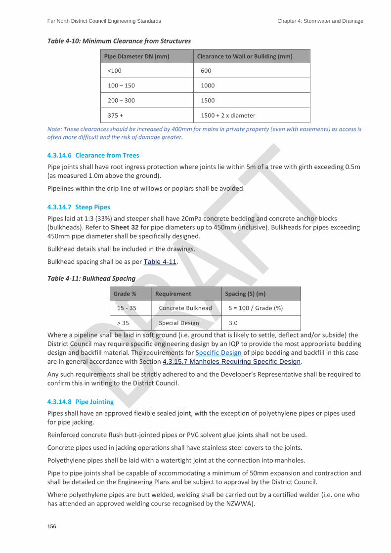
Far North District Council Engineering Standards Chapter 4: Stormwater and Drainage
156
Table 4-10: Minimum Clearance from Structures
Pipe Diameter DN (mm) Clearance to Wall or Building (mm)
<100 600
100 – 150 1000
200 – 300 1500
375 + 1500 + 2 x diameter
Note: These clearances should be increased by 400mm for mains in private property (even with easements) as access is often more difficult and the risk of damage greater.
4.3.14.6 Clearance from Trees
Pipe joints shall have root ingress protection where joints lie within 5m of a tree with girth exceeding 0.5m (as measured 1.0m above the ground).
Pipelines within the drip line of willows or poplars shall be avoided.
4.3.14.7 Steep Pipes
Pipes laid at 1:3 (33%) and steeper shall have 20mPa concrete bedding and concrete anchor blocks (bulkheads). Refer to Sheet 32 for pipe diameters up to 450mm (inclusive). Bulkheads for pipes exceeding 450mm pipe diameter shall be specifically designed.
Bulkhead details shall be included in the drawings.
Bulkhead spacing shall be as per Table 4-11.
Table 4-11: Bulkhead Spacing
Grade % Requirement Spacing (S) (m)
15 - 35 Concrete Bulkhead S = 100 / Grade (%)
> 35 Special Design 3.0
Where a pipeline shall be laid in soft ground (i.e. ground that is likely to settle, deflect and/or subside) the District Council may require specific engineering design by an IQP to provide the most appropriate bedding design and backfill material. The requirements for Specific Design of pipe bedding and backfill in this case are in general accordance with Section 4.3.15.7 Manholes Requiring Specific Design.
Any such requirements shall be strictly adhered to and the Developer’s Representative shall be required to confirm this in writing to the District Council.
4.3.14.8 Pipe Jointing
Pipes shall have an approved flexible sealed joint, with the exception of polyethylene pipes or pipes used for pipe jacking.
Reinforced concrete flush butt-jointed pipes or PVC solvent glue joints shall not be used.
Concrete pipes used in jacking operations shall have stainless steel covers to the joints.
Polyethylene pipes shall be laid with a watertight joint at the connection into manholes.
Pipe to pipe joints shall be capable of accommodating a minimum of 50mm expansion and contraction and shall be detailed on the Engineering Plans and be subject to approval by the District Council.
Where polyethylene pipes are butt welded, welding shall be carried out by a certified welder (i.e. one who has attended an approved welding course recognised by the NZWWA).

Far North District Council Engineering Standards Chapter 4: Stormwater and Drainage
157
4.3.14.9 Curved Pipelines
Curved pipelines may be approved in specific cases provided that:
The pipeline is specifically designed,
Installation is closely controlled to ensure grade and alignment are to the design, and
As-built information is provided to enable any part of the curved pipeline to be re-located by the District Council to within ± 0.1m.
4.3.15. Manholes
4.3.15.1 General Requirements
Manholes shall be located:
On District Council property or Transport Corridors whenever practicable. If located within the carriage way, manholes shall be located 2m out from the kerb.
Out of hollows, dips or any area that may be subjected to inundation or identified as a secondary flow path.
Clear of all boundary lines by at least 1.5m from the side of the manhole chamber plus the height of any nearby retaining walls if they exist.
2m clear of existing structures in private property as per FNDC Policy #0022 - Building Over Public Sewers.
Manholes are required at the following locations:
Intersection of pipes except for junctions between mains and lateral connections,
Changes of pipe size,
Changes of pipe direction, except where horizontal curves are approved,
Changes of pipe grade, except where vertical curves are approved,
Combined changes of pipe direction and grade, except where compound curves are approved,
Changes of pipe invert level,
Changes of pipe material, except for repair/maintenance locations,
Permanent ends of a pipe,
Discharge of a pressure main into a gravity pipe,
Discharge from a wastewater overflow in to the stormwater system.
For infill developments, manholes are not required at 150 mm branch connections onto 150 mm mains provided that:
a manhole exists on the main within 100 m of the connection point: and,
an ‘off-line’ manhole is provided on the branch upstream of the connection point: and,

Far North District Council Engineering Standards Chapter 4: Stormwater and Drainage
158
the ‘off-line’ manhole is immediately within the boundary of the property being served (subject to access requirements), or within 20 m of the connection point, whichever is the lesser.
4.3.15.2 Spacing
For reticulation pipes, the maximum distance between any two manholes shall be 120m.
4.3.15.3 Allowable Deflection through Manholes
A maximum allowable deflection through a manhole for pipe sizes 150 to 225DN is 90 degrees. The maximum allowable deflection for pipe sizes greater than DN225 is 110 degrees.
4.3.15.4 Internal fall through Manholes
In addition to the normal pipeline gradient, all manholes shall have a minimum drop of 20mm plus 5mm per 10 degrees of the angle of change of flow within the manhole.
The construction tolerance for drop through the manhole shall be:
Constructed Manhole Drop = Manhole Drop (as calculated above) +/- 5 mm
Grading the channel shall be limited to falls through manholes of up to 150mm.
To avoid excessively deep channels within manholes, steep grades shall be 'graded-out’ at the design phase where practicable.
4.3.15.5 Size of Manholes
Manholes shall be a minimum of 1050mm diameter for depths of 1.0m or more.
Manholes of 600mm diameter are approved to be used for depths less than 1.0m at the upstream end of public stormwater networks.
4.3.15.6 Materials and Parameters
Pre-cast concrete manholes with external flanged base are acceptable provided that:
They shall be installed in accordance with Sheet 39,
Manholes up to 2.4m deep shall be constructed using a single riser with a pre-cast external flange base,
Manholes in excess of 2.4m deep shall be constructed using a 2.4m deep pre-cast riser with external flange base, and then completed to final ground level using no more than a single riser for manholes up to 5.0m deep. Three risers are allowable for manholes in excess of 5.0m depth,
In no case shall a series of short risers be used,
The joints of all abutting units shall be sealed against the ingress of water,
The cover frame shall be set over the opening and adjusted to the correct height and slope using adjustment rings and mortar so as to conform to the surrounding surface,
The cover frame shall be held in place with concrete haunching in accordance with Sheet
39.
Manholes constructed and installed using alternative materials and methodologies shall be in accordance with FNDC Approved Materials List - Wastewater and Stormwater and installation details.

Far North District Council Engineering Standards Chapter 4: Stormwater and Drainage
159
4.3.15.7 Manholes Requiring Specific Design
Specific Design of manholes shall be undertaken by an IQP and Appendix C ES – PS1 or approved alternative certification provided.
Where manholes are more than 5.0m deep they shall be specifically designed in accordance with the manufacturer’s requirements for external pressures and to resist floatation.
The manhole foundation shall be able to support all design loads placed on it for the duration of the lifecycle of the manhole (and pipeline) it supports. Where the foundation soil may not provide adequate support for the manhole or pipes, the manhole foundation and associated pipelines shall be specifically designed to prevent damage from practicable ground movement. Acceptable methods include:
Use of geotextile fabric:
Cement stabilisation: or
Removal of unsuitable material and replacement with compacted selected material.
Use of groundwater drainage as a means for stabilising pipeline foundations requires Council’s specific approval.
In areas of high-water table, all manholes shall be specifically designed to provide a factor of safety against flotation of 1.25.
Reinforced concrete manholes in suspected or proven aggressive ground conditions shall be specifically designed.
Manholes utilizing materials other than reinforced concrete shall be specifically designed when installation conditions fall outside of the manufacturer’s recommendations.
4.3.15.8 Flotation
In areas of known or practicable high-water table, all manholes shall be designed to provide a factor of safety against flotation of 1.25.
4.3.15.9 Connections to Manholes
The invert of a la tera l property connection to a manhole sha l l be at a level no lower than the average of the soffit levels of the main inlet and outlet pipes.
The invert of other lateral (pipeline) connections shall achieve the internal fall requirements of Section
4.3.15.4 Internal fall through Manholes. Maximum angle of deflection of lateral connection into the manhole main channel shall be 90 degrees.
Internal drops shall only be approved where manhole diameters are 1200mm or greater and shall be as per Sheet 39.
External drops shall require specific approval.
4.3.15.10 Covers
Watertight manhole covers with a minimum clear opening of 600mm in diameter, complying with AS 3996:2006, shall be used.
‘Non-rock’ covers shall be used on all State Highway and Level 2 roads (roads with greater than 10,000 vehicles per day).
Class D covers to AS 3996:2006 shall be used in the Transport Corridor, carriageway, commercial and industrial properties and all public areas.
Class B and Class C covers to AS 3996:2006 may only be used on residential properties.
Note: bolted down covers shall not be used.

Far North District Council Engineering Standards Chapter 4: Stormwater and Drainage
160
4.3.15.11 Manhole Steps
All manholes greater than 1m in depth shall be provided with 20mm diameter stainless steel step irons in order to provide access. These shall be of the ‘dropper’ or ‘safety’ type to prevent feet sliding sideways off them.
Manhole steps shall be provided at 300mm centers vertically (refer Sheet 39). The top step shall not be more than 450mm below the top of the top slab and the lowest step shall be no more than 375mm above the bench, or such lower level if specified by manufacturers of proprietary manholes.
4.3.16. Connections
4.3.16.1 General Requirements
The lateral connection should be designed to suit the existing situation and any future development.
For connections to an open watercourse, resource consents from Northland Regional Council may be required.
Section 4.2.4 Discharge to the Road Kerb.
4.3.16.2 Lot Connections
The following design requirements shall be met:
Stormwater management as per hierarchy in Section 4.1.7 Stormwater Management Hierarchy.
Where no other option is available, a ‘bubble-up’ discharge to the kerb and channel will be required in the residential high density, commercial and industrial areas. The less expensive Kerb and Channel connections will only be approved in place of 'bubble-up' outlets in normal residential zones where, there is a suitable kerb profile and, the Kerb and Channel can be installed at least 1.0m clear of any vehicle crossing.
The preferred depth at the boundary, of a stormwater connection to a piped network, is 1.2m (allowable range 0.9m - 1.5m) where practical, subject to the following:
i. The connection shall satisfy the pipe size, material, cover, depth and self -cleansing velocity requirements of these standards;
ii. The connection shall be able to service the whole developable area of the lot; and,
iii. The connection shall be able to convey the expected flow from the whole developable area.
Note: The “whole developable area” is that area on the lot that can reasonably be expected by the designer to be developed in future in accordance with the proposed land use. The District Plan building and setback rules may provide designers with an indication of the size and location of developable areas within lots.
To determine whether a connection can clearly serve the whole developable area of the lot, the invert level should be calculated at grade of 1:80 from the pipe invert to the lot boundary and then at 1:100 to the furthest point within the lot. If after allowing for the pipeline diameter, the depth of soil cover over the pipeline is less than 0.5m the final design will shall be to the satisfaction of the District Council.
Existing connections, not documented on District Council records may be reused subject to confirmation of existing construction suitability and as-built information is provided to update District Council's records.

Far North District Council Engineering Standards Chapter 4: Stormwater and Drainage
161
Detention of stormwater prior to release to the District Council network is required. Early consultation is encouraged with District Council staff to seek a suitable solution at the outset of the development.
As a guide only, a simplified assumption for infill residential development where the extension of District Council services or creation of overland flow paths suitable to cater for the 100-year storm event through a neighbouring property is difficult, the design may be based on the following.
Minimum size for connections:
100mm for each residential allotment, or
150mm for a commercial/industrial lot. The connection shall be designed to suit the potential site coverage, and where known, the intended use of the property.
The minimum connection size will only be suitable for small lots.
Where discharge rate controls are applied, the District Council may approve alternative connection sizes.
All connections, which shall be made directly to the line, shall be designed using a factory manufactured ‘wye’ or ‘London Junction’ and shall be watertight.
Connections shall be sited clear of obstructions and known developments and accessible for maintenance.
Direct connection of branch pipelines to main pipelines is acceptable, provided:
Connection is via a suitable junction or saddle where the branch pipe d iameter is not greater than half the main pipe diameter,
The distance between the pipeline connection and the closest inspection point is not greater than 25m.
Connections shall be sealed with removable caps until required. The caps are to be painted green and have ‘SW’ painted/fixed onto the end cap.
4.3.16.3 Services in Accessways, Access Lots, Rights of Way or Multi-Unit Properties
Refer to the FNDC Stormwater Management Bylaw 2014 for requirements.
4.3.17. Catch-Pits
The design and construction of catch-pits for public roads shall be undertaken so that:
An appropriate flow capture rate is demonstrated and used, which allows for 50% blockage of the inlet grate.
Catch-pits are capable of capturing and retaining the majority of gross pollutants, and floatable contaminants including oil and grease where required, to assist compliance with the water quality requirements of Auckland Regional Council TP10.
Technology regarding pre-treatment devices within catch-pits is continuously evolving. Where devices are required, consultation with the District Council is required to ensure the proposed device meets with District Councils operations and maintenance requirements. Any Alternative Designs of stormwater catch-pits shall be capable of capturing and retaining the majority of gross pollutants and floatable contaminants such as oil and grease.
Catch-pits shall be accurately positioned so that the grate and kerb block fit neatly into the kerb and channel. Rectangular pits shall be oriented with the longer side parallel to the kerb.

Far North District Council Engineering Standards Chapter 4: Stormwater and Drainage
162
Catch-pits shall be fitted with removable grates, which allow maintenance whi le preventing accidental access, and that are suitable for crossing by bicycles.
Catch-pits shall be placed:
i. at maximum 90m intervals on roadways unless specifically designed,
ii. where the location prevents primary flow from bypassing the catch-pit inlet, e.g. upstream of right of way crossings or pram crossings, at tangent points, and discharging overland,
iii. to capture the design runoff flow from the identified contributing area, including adjacent road, paths and public or private land,
Catch-pit leads shall be at minimum pipe gradient of 1%, and minimum 300mm diameter for a single catch-pit, and minimum 375mm diameter for a double catch-pit,
Catch-pit leads not more than 300mm diameter and not more than 20m in length may be saddled on to pipes 600mm diameter and larger, without manholes,
Double catch-pits shall be placed at sags/low points, on gradients exceeding 8%, or at any other locations with the potential for ponding or for flow to leave channels, and
In accordance with Sheet 34.
Catch-pits on private access-ways shall be capable of accepting the flow from the catchment area. The minimum grate size shall be 300 x 300mm. Where an access way is steep, or stormwater connections discharge onto the access-way, standard single or double catch-pits as required for roads, and detailed on Sheet 34 shall be used. Catch-pit leads shall be adequate for the catchment area, but not less than 150mm.
4.3.18. Subsoil Drains
Subsoil drains shall be installed to control groundwater levels if required.
Perforated or slotted pipe used under all areas subject to vehicular traffic loads shall comply with NZTA F2:2013, including the notes. The design for subsoil drains shall include regular inspection and flushing points.
In the absence of any other more appropriate criterion the design flow for subsoil systems shall be based on a standard of 1mm/h (2.78 L/s/ha).
Subsoil drainage servicing private property will not be adopted by the Far North District Council. (Refer Sheet 14)
4.3.19. Infiltration Systems
Soakage devices such as soak pits and soak holes, filter strips, infiltration trenches and basins, permeable paving, green roofs, and tree pits may be considered for managing stormwater from roofs, parking areas, and roads.
The ability of the ground to accept stormwater can vary enormously within soakage areas, even within individual properties. Because of this, at least one percolation test shall be required for every infiltration device that is constructed and this should be done where the device is likely to be placed.
Infiltration (with storage) shall be utilised where infiltration test results exceed 150mm/hr, as determined using the NZ Building Code E1 Method, and where other conditions (e.g. stability, groundwater) do not preclude their use. Infiltration rates may be determined using the test and calculation procedure set out in the worksheet in Appendix F Permeability Test Sheets.

Far North District Council Engineering Standards Chapter 4: Stormwater and Drainage
163
Calculations of infiltration storage volumes shall identify the most severe combination of rainfall and infiltration/discharge for all storm durations. This shall then be used to determine the size of the infiltration storage facility.
Infiltration systems shall be designed so as to be serviceable, and shall consider geotechnical suitability and hydrogeological suitability for the specific application and/or site.
Infiltration system design requires Specific Design as follows:
Infiltration ponds shall be specifically designed and shall comply with the same criteria as outlined in Section 4.3.20 Stormwater Treatment and Detention Devices for attenuation ponds,
Permeable pavement and associated porous sub-base shall be specifically designed,
Specific engineering design is required for infiltration systems in soils with infiltration rates less than 150mm/hr.,
Specific matters to be considered in soakage system design include:
Infiltration systems shall be designed for 1% (+20%) AEP flows from impervious areas,
Capacity adequate for the maximum potential impermeable area and located in such a way to maximise the collection of site runoff,
Infiltration devices shall be located away from overland flow paths,
Rate of infiltration determined through an infiltration test with an appropriate reduction factor (at least 0.25) applied to accommodate loss of performance over time,
Secondary flows shall be provided for the water which will follow during events that exceed the design capacity of the infiltration device,
Confirmation that the infiltration system will not have an adverse effect on surrounding land and properties from land stability, seepage, flooding or overland flow issues,
Pre-treatment device to minimise silt ingress,
Interception of hydrocarbons,
Access for maintenance,
Specific matters to be considered when locating soakage systems include:
Infiltration devices shall not be located close to buildings or boundaries. A clearance of 3.0m is required, but this can be reduced to 1.0m for porous paving or can be reduced to 1.5m where the neighbouring property is required to have a 1.5m setback to any new building. Setbacks to roadside boundaries shall be 0.5m (to avoid fence footings). Further encroachment will require a site-Specific Design (including PS1 certification) to be carried out.
Infiltration devices should not be located beside retaining walls. For walls less than 2.0m high, the clearance shall not be less than a horizontal distance that is equal to the retaining wall height plus 1.5m, unless a site-Specific Design (including PS1 certification) is carried out. For walls higher than 2.0m, a site-Specific Design shall always be carried out.
Infiltration devices shall not be located within 2.0m of public sanitary sewers or 1.0m of private sewers.

Far North District Council Engineering Standards Chapter 4: Stormwater and Drainage
164
Infiltration devices shall not be positioned on unstable slopes (refer Section 4.3.3
Infiltration and Stability).
Infiltration devices shall be positioned above the ‘winter’ high water table unless specifically approved to operate as predominately summer infiltration systems. In the absence of specific field data, the position of the high water table can be estimated from boreholes or test pit observations of soil colouration and wetness.
On lot infiltration devices shall not be shared between properties.
A discharge permit may be required from the Northland Regional Council.
4.3.20. Stormwater Treatment and Detention Devices
4.3.20.1 General
There are a number of treatment and detention options available. The preferred solution will either be identified in an approved Catchment Management Plan, or through discussions with the District Council.
The District Council will assess options based on the following considerations:
The lifecycle maintenance cost for the District Council,
Land limitations such as available area, stability or ownership,
The suitability of locating a device in the locality,
The engineering capacity and efficiency of the device, and
The optimisation of land use and detention and treatment facilities in the growth area
Proposed engineering and landscape designs or works for treatment and detention solutions shall be approved at the sole discretion of the District Council.
Where proposed stormwater treatment and detention solutions may impact on the operation or maintenance of other District Council assets, e.g. road pavements, reserves, underground services, then specific approval from the relevant affected department is also required.
Design shall follow the guidance provided in Auckland Regional Council TP10. The specific requirements as set out in this Section take precedence over Auckland Regional Council TP10.
If the District Council shall be ultimately responsible for maintenance the treatment or detention device shall be located on land owned by, or to be vested in Council or protected by an appropriate easement in favour of the District Council.
The District Council encourages early consultation between the Developer and District Council staff to achieve mutually beneficial design outcomes. Of particular note the District Council seeks design outcomes that meet functional requirements whilst avoiding poor visual results.
4.3.20.2 Reduction for Re-Use
Rainwater tanks can provide a significant contribution to stormwater attenuation when they provide the sole water supply for a domestic dwelling.
Table 4-12 sets out the percentage reduction of the required attenuation volume attributable to the
dwelling roof. The table is based on a water consumption of 250 litre/person/day.
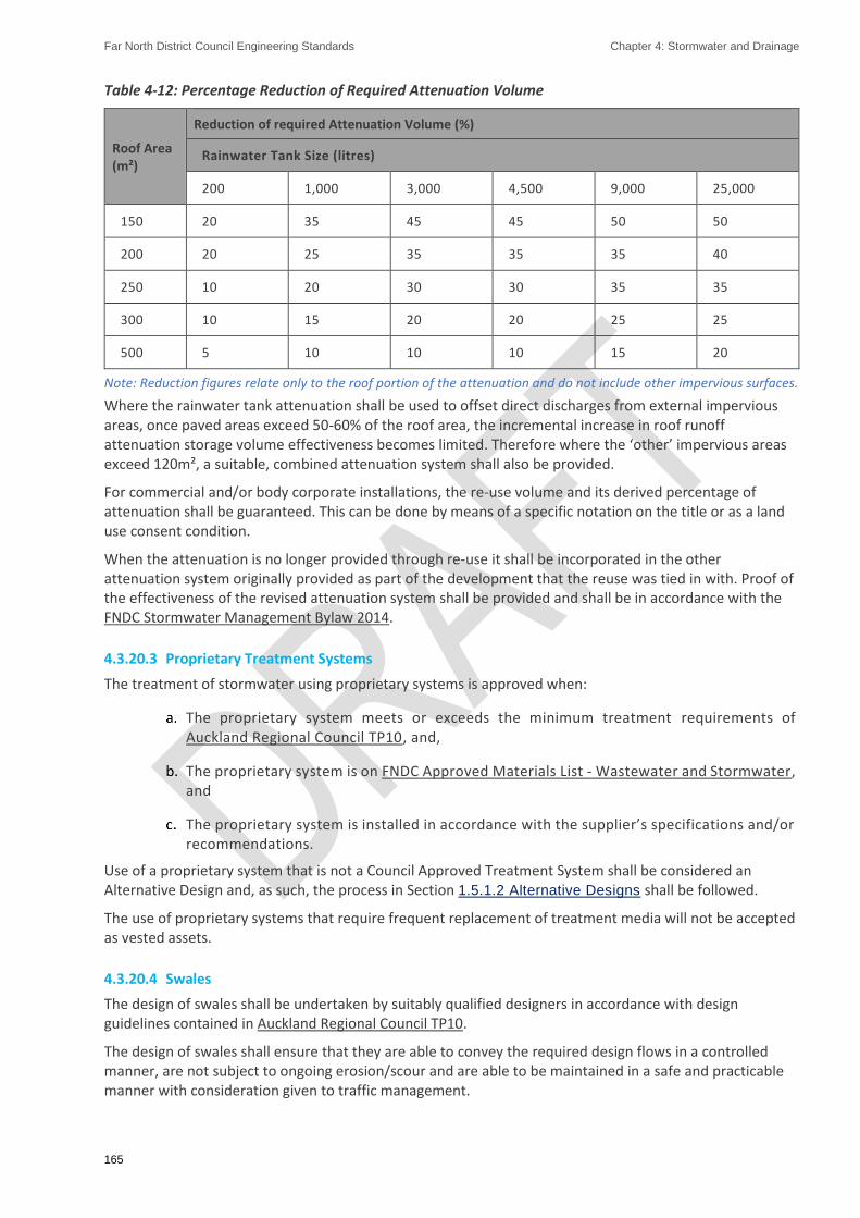
Far North District Council Engineering Standards Chapter 4: Stormwater and Drainage
165
Table 4-12: Percentage Reduction of Required Attenuation Volume
Roof Area (m²)
Reduction of required Attenuation Volume (%)
Rainwater Tank Size (litres)
200 1,000 3,000 4,500 9,000 25,000
150 20 35 45 45 50 50
200 20 25 35 35 35 40
250 10 20 30 30 35 35
300 10 15 20 20 25 25
500 5 10 10 10 15 20
Note: Reduction figures relate only to the roof portion of the attenuation and do not include other impervious surfaces.
Where the rainwater tank attenuation shall be used to offset direct discharges from external impervious areas, once paved areas exceed 50-60% of the roof area, the incremental increase in roof runoff attenuation storage volume effectiveness becomes limited. Therefore where the ‘other’ impervious areas exceed 120m², a suitable, combined attenuation system shall also be provided.
For commercial and/or body corporate installations, the re-use volume and its derived percentage of attenuation shall be guaranteed. This can be done by means of a specific notation on the title or as a land use consent condition.
When the attenuation is no longer provided through re-use it shall be incorporated in the other attenuation system originally provided as part of the development that the reuse was tied in with. Proof of the effectiveness of the revised attenuation system shall be provided and shall be in accordance with the FNDC Stormwater Management Bylaw 2014.
4.3.20.3 Proprietary Treatment Systems
The treatment of stormwater using proprietary systems is approved when:
The proprietary system meets or exceeds the minimum treatment requirements of Auckland Regional Council TP10, and,
The proprietary system is on FNDC Approved Materials List - Wastewater and Stormwater, and
The proprietary system is installed in accordance with the supplier’s specifications and/or recommendations.
Use of a proprietary system that is not a Council Approved Treatment System shall be considered an Alternative Design and, as such, the process in Section 1.5.1.2 Alternative Designs shall be followed.
The use of proprietary systems that require frequent replacement of treatment media will not be accepted as vested assets.
4.3.20.4 Swales
The design of swales shall be undertaken by suitably qualified designers in accordance with design guidelines contained in Auckland Regional Council TP10.
The design of swales shall ensure that they are able to convey the required design flows in a controlled manner, are not subject to ongoing erosion/scour and are able to be maintained in a safe and practicable manner with consideration given to traffic management.

Far North District Council Engineering Standards Chapter 4: Stormwater and Drainage
166
Refer to Section 3.2.14.4 Swales for use of swales within the Transport Corridor as road pavement drainage controls.
4.3.20.5 Raingardens
The design of raingardens (often referred to as bio-retention) shall be undertaken by suitably qualified designers in accordance with design guidelines contained in Auckland Regional Council TP10.
The design of raingardens shall ensure that they can detain and treat the required water quality volume, can adequately drain between events through underdrainage and are able to be maintained in a safe and practicable manner with consideration given to traffic management.
Refer to Section 3.2.14.4 Swales for use of bio-retention within the Transport Corridor as road pavement drainage controls.
4.3.20.6 Underground Storage
Typical specifications for underground storage devices are provided in Table 4-13. Treatment train consideration is essential, including an upstream Gross Pollutant Trap for protection and maintenance purposes.
Table 4-13: Proprietary Underground Storage Specifications
Parameter Specification
Landuse
Non trafficked areas, e.g. landscapes.
Carparks (vehicles up to 2,500kg gross mass.
Trafficked areas, vehicle greater than 2,500kg gross mass.
Performance
Depending on the design, the storage tank can provide:
Retention (infiltration) storage and/or Detention storage.
Shall be part of a treatment train.
Sizing
Provide to achieve requirements of Section 4.1.3 Performance Standards and Table
4-2 as required.
Consult manufacturer’s guidance for detailed sizing information.
Depending on the device location minimum cover depths will apply.
4.3.20.7 Catch-Pit Filter System
Table 4-14 summarises design requirements for typical catch-pit filter system (CFS) applications.
As systems are manufacturer specific, general specifications have been provided. Catch-pit filter systems required Specific Design.
Table 4-14: Catch-Pit Filter Specifications
Parameter Specification
Landuse
Shopping malls
Schools - Carparks
Roads
Catchment area
Less than 1 Ha

Far North District Council Engineering Standards Chapter 4: Stormwater and Drainage
167
Parameter Specification
Performance
Gross pollutant removal.
Some course sediment removal.
Shall be part of a treatment train.
Sizing
Installed into a curb inlet or catch-pit and can be customized to meet specifications.
High flows are designed to bypass.
Drainage design should account for loss of inlet capacity to system.
4.3.20.8 Constructed Ponds and Wetlands
Ponds shall comply with the following minimum requirements:
Maximum permanent water depth is 1.5m,
External slopes shall be 1(v):4(h),
Internal slopes shall be 1(v):4(h),
The pond shall be contained within the legal boundaries of a drainage reserve,
Where ponds are not fenced, safety benches are constructed around the full perimeter in accordance with section 4.3.20.9 Pond Safety Requirements,
All weather, legal access to the area from a road shall be provided for maintenance for District Council vested systems,
Vehicle/machinery access into the fore-bay of wet ponds, or the main bay of dry ponds, shall have a min width of 2.5m and a max gradient of 35% (1/3),
Perimeter access and access to inlet and outlet structures for maintenance should be considered in the design,
Hazards from the area shall be identified and mitigated,
Access for maintenance vehicles shall be provided within the fence surrounding the pond when installed,
Specific approval is required from the District Council to locate a stormwater detention pond within a Local Purpose Reserve.
Prior to vesting of any stormwater pond or wetland, an Operations and Maintenance Manual shall be finalised and provided to the District Council, including any alterations discussed and agreed with the District Council. This includes any changes required by Northland Regional Council for consent compliance.
4.3.20.9 Pond Safety Requirements
The following safety requirements shall be provided in addition to, or in preference to, the safety requirements in Auckland Regional Council TP10:
The treatment and detention devices shall not compromise the safety of adjacent properties or the community, National Guidelines for Crime Prevention through Environmental Design in New Zealand principles (refer to Section Error! Reference source not found. Error!
Reference source not found.) shall be incorporated.
Embankments shall be permanently planted if the slope ratio is steeper than 1 (vertical) to 4 (horizontal).

Far North District Council Engineering Standards Chapter 4: Stormwater and Drainage
168
Any embankment that the District Council determines is either too inaccessible or unsafe for regular grass mowing shall be permanently planted.
A safety bench shall be provided between the normally dry water level and the deep water where deep pools of greater than 0.9m are proposed. The safety bench shall be between 0.3m and 0.5m below normal water level and between 0.5m and 1.0m wide. Additional safety bench(s) are required each 5.0m where slopes greater than 1:3 lead to a deep water pond. Safety benches are not required where fencing is applied as per e. below. Benches shall be stabilised with emergent wetland plants and wet seed mixes.
Any part of stormwater structures having either a vertical drop of 0.9m or the ability to fall directly into standing water of depth greater than 0.9m shall be fenced in 50% permeable format and otherwise compliant with the Building Act 2004.
Note: Fencing across overland flow paths requires Specific Design by an IQP and approval by the District Council.
4.3.20.10 Planting and Aesthetic Requirements
Any discharge risers shall have a 1.0m wide concrete apron or band around the external portion. Between this apron and 2.0m from the riser, carex virgata and/or carex geminata shall be planted on the embankment with mulch matting, unless otherwise specified by the District Council. No other plant species, including grassing, may be installed within 2.0m of the outlet
Aesthetic design elements shall be in keeping with local character. Consider:
Integrating planting into the wider environment such as streetscape and/or park setting so that the planting is seamless (where this is desired),
Extending the footpath into wetland area as a boardwalk, and
Making the wetland shape and edges aesthetically appealing
Ensure that the planting, once established, promotes desirable views and focal points of interest, and does not visually block traffic intersections, property entrances, pedestrian and/or cycleway paths.
Landscaping shall:
Comply with engineering requirements,
Minimise ongoing maintenance,
Improve stormwater water quality discharge,
Retain existing bush areas and tree stands where practicable,
Become a community asset and positive visual amenity, and
Provide, where practicable, forage and habitats for native flora and fauna,
Planting plans shall be submitted to the District Council for approval.
Plant species allocations shall be specific to soil type and conditions, site topography and exposure, post-development groundwater table levels and alignment with local indigenous native plant species. Plant species shall be indigenous to the Northland Region, although native New Zealand grasses are permitted. Where practicable, plants shall be from the Northland Region.
Of the vegetation mix in wetlands at least 10 percent and no more than 25 percent shall be staked 1.5m high grade trees.
Woody vegetation and trees are not to be planted within 3.0m of the slope of the toe of wetlands and ponds to prevent future bank stability issues when the plant reaches the end of its lifecycle and its root systems decompose.
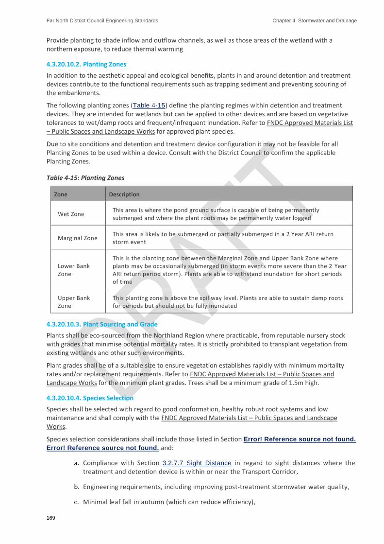
Far North District Council Engineering Standards Chapter 4: Stormwater and Drainage
169
Provide planting to shade inflow and outflow channels, as well as those areas of the wetland with a northern exposure, to reduce thermal warming
4.3.20.10.2. Planting Zones
In addition to the aesthetic appeal and ecological benefits, plants in and around detention and treatment devices contribute to the functional requirements such as trapping sediment and preventing scouring of the embankments.
The following planting zones (Table 4-15) define the planting regimes within detention and treatment devices. They are intended for wetlands but can be applied to other devices and are based on vegetative tolerances to wet/damp roots and frequent/infrequent inundation. Refer to FNDC Approved Materials List – Public Spaces and Landscape Works for approved plant species.
Due to site conditions and detention and treatment device configuration it may not be feasible for all Planting Zones to be used within a device. Consult with the District Council to confirm the applicable Planting Zones.
Table 4-15: Planting Zones
Zone Description
Wet Zone This area is where the pond ground surface is capable of being permanently submerged and where the plant roots may be permanently water logged
Marginal Zone This area is likely to be submerged or partially submerged in a 2 Year ARI return storm event
Lower Bank Zone
This is the planting zone between the Marginal Zone and Upper Bank Zone where plants may be occasionally submerged (in storm events more severe than the 2 Year ARI return period storm). Plants are able to withstand inundation for short periods of time
Upper Bank Zone
This planting zone is above the spillway level. Plants are able to sustain damp roots for periods but should not be fully inundated
4.3.20.10.3. Plant Sourcing and Grade
Plants shall be eco-sourced from the Northland Region where practicable, from reputable nursery stock with grades that minimise potential mortality rates. It is strictly prohibited to transplant vegetation from existing wetlands and other such environments.
Plant grades shall be of a suitable size to ensure vegetation establishes rapidly with minimum mortality rates and/or replacement requirements. Refer to FNDC Approved Materials List – Public Spaces and Landscape Works for the minimum plant grades. Trees shall be a minimum grade of 1.5m high.
4.3.20.10.4. Species Selection
Species shall be selected with regard to good conformation, healthy robust root systems and low maintenance and shall comply with the FNDC Approved Materials List – Public Spaces and Landscape Works.
Species selection considerations shall include those listed in Section Error! Reference source not found.
Error! Reference source not found. and:
Compliance with Section 3.2.7.7 Sight Distance in regard to sight distances where the treatment and detention device is within or near the Transport Corridor,
Engineering requirements, including improving post-treatment stormwater water quality,
Minimal leaf fall in autumn (which can reduce efficiency),

Far North District Council Engineering Standards Chapter 4: Stormwater and Drainage
170
Ensuring no species that drop branches, debris, or may in any other way cause damming and/or unplanned flooding in and adjacent to watercourses (such as streams and spillways) are planted within 5.0m of watercourses.
Where trees, shrubs and groundcovers shall be planted within a Transport Corridor, reference shall be made to Section 3.2.25 Trees and Landscaping.
4.3.20.10.5. Swales Planting
Swales may be turfed or grassed to ensure rapid establishment and mitigate channel surface scouring. Grass should be maintained at heights between 50mm and 150mm, depending on engineering design parameters.
Where engineering requirements permit, Carex virata or Carex geminata may be planted in the Wet and Marginal Zones. No other groundcover, shrub or tree species are permitted in these Zones. These shall be planted with mulch rounds.
Table 4-16: Swale Planting - Velocity/Grade Matrix
Type Grade Velocity
Swale – Roll on Turfing Less than 2% Less than 1.5m/s at 10 year ARI flow
Swale – Vegetated (Carex grasses) 2-5% Less than 2.5m/s at 10 Year ARI flow
Swale – Rocks Greater than 5% 2.5m/s or greater at 10 Year ARI flow
Turfed swales shall be prepared, established and maintained as per the Section Error! Reference source
not found. Error! Reference source not found.. Both during and post-establishment, the height of the turf shall be consistently maintained at least fortnightly to the designed stormwater engineering requirements. Turf shall be of a drought- resistant hard-wearing ryegrass-based variety with no weed species.
Swales planted with Carex species shall be planted according to Section Error! Reference source not
found. Error! Reference source not found..
4.3.20.10.6. Filter Planting
Filters can be planted with a mix of District Council approved groundcovers, shrubs and trees from the FNDC Approved Materials List – Public Spaces and Landscape Works as site conditions and engineering requirements permit.
4.3.20.11 Maintenance Requirements
Access to wetlands and ponds shall be as follows:
A 4.0m wide access driveway and platform (as applicable) with all-weather surface suitable for an 8.2 tonne axle weight vehicle, at a grade of less than 1:12 shall be provided,
Maintenance access shall be located within any perimeter safety fencing,
The excavator working platform shall be level and adjacent to the clean out area,
The excavator working platform shall be no higher than 2.0m above the base of the clean out area, and
If the access path is greater than 50m long then a 3-point turning area for a 10 tonne rigid truck adjacent to device (in addition to the excavator working platform): shall be provided.

Far North District Council Engineering Standards Chapter 4: Stormwater and Drainage
171
4.3.21. Building Over or Adjacent to Pipelines
The following is not permitted without the District Council’s specific approval (refer to FNDC Wastewater Drainage Bylaw 2018):
a) Building over or within a horizontal distance of 2m measured from the outside of pipe:
b) Building within the zone of influence of the pipe:
c) Building within 2m horizontally of the outside of any maintenance structure (manholes, lampholes, maintenance shafts and sewer dead ends):
d) Driven piles shall not be installed closer than 5m from any pipe unless documentation is provided to the District Council’s satisfaction showing that the proposed works will not damage the asset.
Refer to FNDC Wastewater Drainage Bylaw 2018 for dispensation procedures.

Far North District Council Engineering Standards Chapter 4: Stormwater and Drainage
172
4.4. Construction
4.4.1. Pipeline Installation
This section covers the installation requirements for all piped wastewater and storm water networks.
The installation of pipelines shall be carried out in accordance with AS/NZS 2566.2:2002 (where applicable) and Sheet 31 and Sheet 32.
Pipe pressure rating of PN16 SDR 11 is required for trenchless construction.
4.4.2. Materials
Materials shall be in accordance with the requirements of Section 4.3.7 Approved Materials and FNDC Approved Materials List - Wastewater and Stormwater.
4.4.3. Pipe Installation by Trench
4.4.3.1 Pipe Embedment and Marking
4.4.3.1.1. Embedment
Pipes shall be bedded and protected as specified on the approved drawings. Where not specified on the drawings, bedding and protection shall be in accordance with Sheet 31 and Sheet 32 and the particular manufacturer’s specifications.
The designed trench width shall be sufficient width, (minimum in accordance with Sheet 31), to allow pipes to be safely laid and all embedment material properly and sufficiently compacted.
Embedment and fill shall keep pace with the excavation and laying of pipes so that not more than 15m of pipes shall be left exposed in open trench where this could represent a danger to road users.
The foundation shall be able to support all design loads placed on it for the duration of the lifecycle of the pipeline it supports. Where the bottom of the trench will not provide adequate support for the pipe, the designer shall provide a suitable means to stabilise trench foundation. Acceptable methods include:
Use of geotextile fabric:
Cement stabilisation: or
Removal of unsuitable material and replacement with compacted selected material.
Use of groundwater drainage as a means for stabilising pipeline foundations requires Council’s specific approval.
No embedment material shall be placed or pipes laid before the trench foundation has been inspected and approved by Council.
The various zones comprising the embedment depth shall be laid in ascending order. Each zone shall be laid in accordance with the approved design. Each zone shall contain the specified selected material and compacted to the required density. There shall be no sharp stones or large clay lumps in the bedding or surround.
Where pipelines have protruding projections such as sockets, flanges or couplings, a suitable recess shall be provided, in the supporting material, to ensure the pipeline is fully supported along the pipe barrels.
Pipes made of plastic materials shall be laid with product labelling uppermost in the trench.
Far North District Council Engineering Standards Chapter 4: Stormwater and Drainage
173
4.4.3.1.2. Pipeline Marking
Detection tape shall be laid directly above all new mains. The tape shall have ‘stormwater’ written on it in white and be located at a depth of between 200 and 250mm above the pipe crest.
Where the pipe is not laid in a straight line between manholes the tape shall contain sufficient metal to be detectable from the surface by a standard metal detector.
4.4.3.2 Tolerances
Pipes shall be accurately laid to the lines, levels and gradients shown on the drawings using pipe-laying laser equipment.
The permissible deviation of the alignment and gradient of pipelines shall be the lesser of ± 5% of the nominal diameter of the pipe or ± 20mm from a straight line between the inverts of successive manholes, with all such deviations being gradual. There shall be no steps at the junctions between successive pipes and no point in the pipeline shall be lower than any downstream point.
Where the variation exceeds the tolerance, the District Council may order the removal and relaying of any affected pipes.
4.4.3.2.1. Invert Levels
The permissible deviation from the designated level of the invert at each manhole or structure shall be ± 50mm, provided that the fall between successive manholes or structures shall be at least 90% of that specified.
4.4.3.2.2. Horizontal Alignment
The permissible deviation of the horizontal alignment between manholes or structures shall be ± 100mm.
4.4.3.2.3. Gradient
For straight gradients, the permissible deviation from the specified gradient shall be ± 50mm from a straight line drawn between the inverts of successive manholes, provided that no point in the pipeline is lower than any downstream point.
4.4.3.3 Backfilling and Reinstatement
4.4.3.3.1. General
The trench or embankment fill material and trench reinstatement shall be as specified on the approved drawings. Where not specified on the drawings, fill material and trench reinstatement shall be in accordance with Sheet 31.
Trench or embankment fill shall be compacted in layers to the specified finished level. When compacting in layers the depth of each layer shall be as specified on the approved drawings. Where not specified on the drawings, depths of layers shall be in accordance with Section 4.4.3.3.3 Compaction.
In public areas, backfilling shall keep pace with the laying of pipes so that there is no more than 20m of open trench at any time.
Mechanical compaction of the fill material directly above the pipe shall not be commenced until the depth of cover above the top of the pipe is adequate to prevent damage to the pipe.
Displacement of the laid pipes during backfilling shall be prevented. Compaction equipment which can produce horizontal or vertical earth pressure on the pipeline, which can cause damage or excessive distortion of the pipeline, shall not be used.
The Contractor shall reinstate trenches within 7 days of back fill completion unless agreed otherwise by the Engineer. The surface level of the reinstated trench shall match the surrounding surface level.
All compaction test results shall be submitted to Council for approval.

Far North District Council Engineering Standards Chapter 4: Stormwater and Drainage
174
4.4.3.3.2. Backfill Materials
Except as specified below, selected material excavated from the trench may be used for backfilling trenches. Where reuse of previously excavated material is specified, its selection and use shall be approved by the designer.
In roads and paved areas where material excavated from the trench cannot meet the compaction standards in Section 4.4.3.3.3 Compaction, imported granular material shall be used.
Surplus and unsuitable material from the excavation shall be disposed of at a consented landfill.
4.4.3.3.3. Compaction
Within the Transport Corridor
Trenches in the Transport Corridor, or under private access or paved (vehicular) areas, shall be backfilled and compacted in layers of thickness commensurate with the compaction equipment to a density of at least 95% of the maximum dry density. Field compaction shall be tested as follows:
For cohesive soils - New Zealand standard compaction test, nuclear densometer and shear vane.
For non-cohesive soils - New Zealand standard compaction test, nuclear densometer or dynamic cone penetrometer (Scala Penetrometer).
Testing by other means shall be subject to the approved Inspection and Testing Plan or conditions of Engineering Design Approval.
Compaction testing of sub-base and base course shall be in accordance with requirements 3.3.4 Pavement
Testing.
The designer shall specify a testing regime to verify the compaction effort meets the density specified to support the designed traffic loading.
The Contractor shall undertake tests in accordance with the approved Inspection and Testing Plan or conditions of the Engineering Design Approval, to demonstrate that the specified compaction standards have been achieved throughout.
Outside of the Transport Corridor
Trenches not in roads or paved (vehicular) areas shall be backfilled and well compacted with mechanical equipment in layers not exceeding 300mm thick to the specified finished level.
Under no circumstance shall the bearing capacity of the backfill material be less than that of the material prior to excavation, for the full depth of the trench. Scala Penetrometer tests may be used to establish the criteria for compliance, with a minimum of one test per 50 m of trench or 50 m³ of trench backfill, whichever is greater.
Compaction testing of fill material shall be in accordance with NZS 4402:1988/1986. The Contractor shall undertake tests to demonstrate that the specified compaction standards have been achieved throughout.
4.4.4. Trenchless Construction
4.4.4.1 General
Trenchless technology may be preferable or required as appropriate for alignments passing through or under
Environmentally sensitive areas:
Far North District Council Engineering Standards Chapter 4: Stormwater and Drainage
175
Built-up or congested areas to minimise disruption and reinstatement:
Railway and major road crossings:
Significant vegetation:
Vehicle crossings.
Trenchless construction shall only be used for applications in which the specified tolerance can be achieved.
Pipes used for trenchless installation shall have suitable mechanically restrained joints, specifically designed for trenchless application, which may include integral restraint, seal systems, or heat fusion welded joints.
Any trenchless technology and installation methodology shall be chosen to be compatible with achieving the required gravity pipe gradient.
4.4.4.2 Installation Methods
Trenchless installation methods for new pipes include
Horizontal directional drilling (HDD) (PVC with restraint joint/fus ion welded PE):
Uncased auger boring/pilot bore microtunnelling/guided boring (PVC with restraint joint/fusion welded PE):
Pipe jacking (GRP/ reinforced concrete).
4.4.5. Joints
4.4.5.1 General
Specification of joints on gravity mains shall be as follows.
All pipes shall have flexible joints of an approved type, such as Rubber ringed joints:
Steel pipes shall be flexibly jointed (bolted unrestrained mechanical coupling ‘denso’ wrapped and sealed with approved outer wrapping or approved rubber ring):
Joints shall be provided adjacent to manholes to the requirements of AS/NZS 2566.2:2002 with the exception of PVC where proprietary connections may be used.
4.4.5.2 Rubber Ring Joints
Rubber ring joints shall be installed strictly in accordance with the manufacturer’s instruction. Care should be taken to ensure that the rubber rings are located evenly around the joint with no twists in them. The pipe shall be pushed up firm and tight to the joints.
4.4.5.3 Welding PE Pipes
Butt or electrofusion welding of PE pipes shall be undertaken by a Council approved contractor using calibrated and data logged welding machines. Only employees of an approved contractor who have successfully completed a Water New Zealand approved welding course for polyethylene pipe, or re-fresher in the past two years, shall be permitted to physically undertake welding.
Prior to commencing work, the following shall be provided:
Copy of current calibration certificate(s) of the welding machine (not more than 12 months old)

Far North District Council Engineering Standards Chapter 4: Stormwater and Drainage
176
Registration number of welder, and current certification (not more than 24 months old).
All welding of PE pipe shall be data logged.
Welding shall take place in a covered environment to avoid contamination of weld faces and prepared pipe.
For all electrofusion welds, including tapping saddles, a mechanical scraper with winding mechanism shall be used to ensure even finishing. Hand scraping of pipe ends is not acceptable. Electrofusion welds shall be undertaken using clamps and the equipment correctly calibrated.
4.4.5.3.2. Butt Welded Jointing
In addition, welders may be required to carry out satisfactory test welds for each joint type and to stamp the welder's number on each joint. Butt welds shall be, at least, 90% of the tensile strength of the parent pipe material, when tested in accordance with ISO 13953:2001.
All internal weld beads shall be removed in an approved manner, to be smooth and flush with the pipe inner surface, without compromising the strength of the pipe joint.
4.4.6. Manholes
4.4.6.1 Channels and Benching
A semi-circular channel shall be formed in the concrete floor of the manhole. Benching shall then rise vertically from the spring line of the pipe to the height of the soffit and then be sloped back at a gradient of 1:3 (refer Sheet 39). A U3 standard of finish as specified in NZS 3114:1987 shall be achieved.
The flow channel shall be formed so that it presents an evenly curved flow path through the manhole. The cross section of the flow channel shall be uniform.
Ceramic half pipes shall be saw cut to form mitred joints around bends. Benching shall be floated to a dense, smooth hard surface using 3:1 sand cement mortar and a steel float. Side branches shall be similarly formed with a smooth bend into the main channel.
Use of pre-formed benched manhole bases from FNDC Approved Materials List - Wastewater and Stormwater is an acceptable alternative to formed in-situ benching.
The construction tolerance for drop through the manhole shall be the 4.3.15.4 Internal fall through
Manholes +/- 5 mm.
4.4.6.2 Flexible Joints
All pipe lines, other than PE pipes, shall have a flexible joint adjacent to the manhole on all incoming and outgoing pipes not more than 600mm away from the manhole wall. The upper part of the pipe inside the manhole shall be cut back to the wall, the reinforcement cut out and the ends plastered with a cement mortar to a neat finish. Where the pipe is cut using a power saw the ends of the steel reinforcement shall be protected from corrosion by the application of epoxy before rust has a chance to develop. Refer to Sheet 39.
4.4.6.3 PE Pipe Connections
PE pipe shall be connected to the manholes with sliding joints, as per Sheet 33.
4.4.6.4 Sealing of Manholes
Where precast manhole units are used, the joints of abutting units shall be sealed against ingress of water with an approved sealant and with epoxy mortar on the inside and outside of the joints.
Plastic manholes shall be sealed.

Far North District Council Engineering Standards Chapter 4: Stormwater and Drainage
177
4.4.6.5 Manhole Steps
Bolt through Type Manhole Steps
The steps shall be bolted through the walls using properly formed and recessed bolt holes.
The step shall have a washer welded to it on the appropriate angle to seat flush against the inside of the manhole chamber.
Prior to tightening, BM100 shall be placed around the stainless-steel shank both inside and outside the manhole riser. After the steps have been tightened in place the outside recess which houses the nut shall be sealed with Expocrete ‘UA’ or acceptable equivalent in accordance with the manufacturer’s directions. Plastering of the recess will not be approved. The sealant shall be applied at least 48 hours before the manhole risers are required for construction.
4.4.6.6 Concrete
All concrete shall have a minimum crushing strength of 20.0 MPa at 28 days, unless otherwise specified or detailed by Council.
4.4.7. Connections
Connections will preferably be made into manholes.
Direct connection of a minor pipeline into a major pipeline shall be in accordance with the following:
The minor pipe diameter shall not be greater than half of the major pipe diameter:
Connection is made via a suitable prefabricated junction or saddle:
The distance between the pipeline connection and the closest inspection point shall not exceed 25m:
Saddling of catch-pit leads into primary lines is permitted provided that the connection is made at 45º or less to the direction of primary flow:
Saddling of double catch-pits is not permitted:
Connections shall be sealed with removable caps until required.
Connection locations and depths to invert shall be accurately measured and shown on As-Built Plans in accordance with the requirements of Section 1.7.2 As-Built Plans, Asset
Information Schedules, Operation and Maintenance Manuals:
The connection position shall be marked with a wooden stake (100 x 50mm) with ‘SW’ painted/fixed onto the stake and extending from the invert of the connection to a minimum of 600mm above ground level.
Connections shall be constructed as per Sheet 37.
All connections to District Council piped network or work on District Council piped networks shall be undertaken by an Certified Drainlayer, costs of which are borne by the Developer.
All connections shall be sealed by removable endcaps until such time as they are required.
The endcaps shall be painted green and have ‘SW’ painted/fixed onto the end-cap.
End-cap location shall be measured and shown in accordance with the as-built requirements in Section 1.7.2 As-Built Plans, Asset Information Schedules, Operation and Maintenance Manuals, and show depth to invert from finished ground level or absolute spur invert level.

Far North District Council Engineering Standards Chapter 4: Stormwater and Drainage
178
The end-cap position is also to be marked on the ground with a wooden stake (minimum 100 x 50mm) painted green with ‘SW’ painted/fixed onto the stake, and extending from the invert of the connection to 600mm above ground level.

Far North District Council Engineering Standards Chapter 4: Stormwater and Drainage
179
4.4.8. Catch-Pits
The connection of the lead into the catch-pit shall be constructed as detailed in Sheet 34.
4.4.9. Outlets
The Deve loper shall be responsible for the structural integrity and maintenance of the bank stabilisation/erosion protection structures and for any erosion control works that become necessary to preserve the integrity and stability of the stream, river, channel or water course and/or to control erosion until the structure is vested.
4.4.10. Stormwater Treatment and Detention Devices
4.4.10.1 Planting
Stormwater treatment and detention devices shall be planted as soon as practicable after civil construction is completed according to the Planting Zones indicated in Section 4.3.20.10 Planting and
Aesthetic Requirements. All stormwater features with an inner batter slope ratio of 1 (vertical) to 4 (horizontal) or steeper shall be landscaped as the slope is too great for safe maintenance.
Where site conditions such as unstable soil structures require a more rapid groundcover than shrubs and trees provide, exposed surfaces above the Upper Bank and Lower Bank Planting Zones shall be stabilised with grassing prior to landscape planting.
Planting within the Marginal Zone shall take place at the same time that the upper slopes receive grassing to minimise slope toe erosion. The Wet Zone shall be planted once the normal standing water level has been achieved.
Pond plant species shall be a mix of District Council approved groundcovers, shrubs and trees from the FNDC Approved Materials List – Public Spaces and Landscape Works as site conditions and engineering requirements permit.
Where feasible, consider placing rough logs, dead trees (snags), large rocks/boulders in select locations to encourage wildlife habitats. Ensure that the slope stability, slope toe, inlet, outlet, water flow and forebay are not compromised by the placement of these items and that maintenance can be carried out. Ensure no soil compaction occurs during the installation in surrounding area. The Developer shall consult with an Ecologist and the District Council prior to material selection and placement.
Minimum planting provision requirements are:
Quick establishment of plant cover is required throughout the site, as engineering requirements permit.
No material storage or heavy equipment shall be stored within the site or buffer area after site clearing except to excavate and/or grade site.
All construction and other debris shall be removed prior to topsoil placement.
Soil testing and making adjustments is required (refer to Section Error! Reference source
not found. Error! Reference source not found.).
Unless existing soil is unstable, sloped soils shall be ripped 150mm deep either in a criss-cross pattern or horizontal to base (following contours) prior to topsoil application. Heavy clay will need deeper ripping. Topsoil shall be spread to a minimum 200mm depth, ensuring heavy equipment does not compact the slopes.
Where bark mulch is used, it shall be contained within the plant area that it is providing cover for. Other mulch applications shall be utilised on slopes greater than 1:3.

Far North District Council Engineering Standards Chapter 4: Stormwater and Drainage
180
4.4.10.2 Staged Planting
The staged planting shall be as follows:
4.4.10.2.1. Stage 1: Grassing
Banks shall be prepared and sown with grass seed to establish rapid ground stabilisation, according to Section Error! Reference source not found. Error! Reference source not found..
Where plants shall be established in nitrogen-deficient soils and at the District Council’s discretion, the seed mixture shall be:
Annual Rye Grass 150 kg/ha
Sweet Clover 100 kg/ha
All seed shall be certified and less than 12 months old at the time of sowing. The Ryegrass component shall be certified as having greater than 80% live endophyte content. The District Council may prohibit the use of seed that has deteriorated because of wetting, fertiliser burning, etc. Otherwise the standard landscaping grass seed specifications shall apply as per Section Error! Reference source not found.
Error! Reference source not found..
The site shall be grassed for at least three months and meet establishment requirements for sown areas prior to landscaping. Marginal Zone planting and mulching shall be established at Stage 1.
4.4.10.2.2. Stage 2: Landscape Planting
Stage 2 planting shall occur within the District Council planting season (2 April to 30 September) once Stage 1 sown grass has established. Ensure that no weed species exist throughout the site. Where weed species shall be eradicated carefully spot spray and/or hand-pull in such a manner that erosion is minimised and surrounding groundcover remains undamaged. The sown grass groundcover shall be spot sprayed to 0.50m diameter for each location where individual plants shall be planted four weeks prior to planting, ensuring that the established grass between spot sprays remains undamaged. Maintain sprayed areas so that no new weed growth exists at time of planting. Establish planting and mulching as per Section Error!
Reference source not found. Error! Reference source not found..
4.4.10.3 Plant Spacing
Plants shall be planted according to the following spacing allocations:
Within the Marginal Zone, Carex shall be evenly staggered at 1.0m intervals,
Where plantings are to include approved partially submerged species, these shall be irregularly clumped in groups of 3 to 7 plants along the circumference of the stormwater wetland/pond,
For permanent stormwater ponds, plant 0.4m below the designed normal standing waterline with approved sedges and rushes,
Amenity plantings of tussocks shall be clumped in groups of 3 to 10 plants, and
Trees shall be spaced at minimum 2.5m centres from other trees and underplanted with four equidistant same-species groundcovers, installed 0.75m from the tree stem. The groundcover species shall provide a weed suppression canopy while the tree is establishing, and as such will have no more than 1.0m mature height and minimum 0.75m spread. Ensure that the groundcover species does not compete with the tree establishment requirements. Depending on the Zone planting location, practicable plants could be Phormium 'Green Dwarf', various Carex such as Carex virgata, and Coprosma groundcovers such as Coprosma kirkii 'Minogue',
With respect to the maintenance access track

Far North District Council Engineering Standards Chapter 4: Stormwater and Drainage
181
No shrub or groundcover centres shall be located within 1.0m of the track,
No trees centres shall be located within 2.5m of the track,
Plantings within 2.0m either side of the access track are to have species that are able to recover quickly should they become damaged during pond maintenance, and
In development and shopping precincts, planting design either side of the access track should also ensure that the track may be used for pedestrian amenity purposes.
4.4.10.4 Staking and Protection
4.4.10.4.1. Trees 1.5m High or Greater
Newly planted trees shall be staked with two 50mm x 50mm x 1.8m rough sawn Pine H5 treated stakes with at least one third of their length (600mm) in the ground and at least 1.0m exposed minimum, or as specified on the plan with the approval of the District Council. All stakes shall be inserted to avoid hitting the root ball. Stakes shall be at least 400mm away from the tree trunk and no more than 500mm away.
Two flexible ties per stake shall be attached. Ties shall be tensioned to avoid chafing of the tree against the stakes but with enough play for the tree to move in the wind. All ties shall be fixed to the stakes. Ties shall be of a type approved by the District Council prior to tying. Ties shall be fixed to the outer stake face with a minimum of four staples in a square pattern.
4.4.10.4.2. Smaller Grade Staking
All tree species planted at Pb3 to Pb18 grades and all shrub species planted at greater than Pb8 grades shall be staked with a single 1.2m minimum long 22mm to 25mm diameter dead bamboo stake, positioned outside the rootball, driven into the ground to at least a 400mm depth. The stake shall be fastened two thirds up the plant stem/trunk with a District Council approved interlocking tree tie (e.g. Treelock). If the tree tie is not biodegradable:
The tie shall be adjusted periodically so that the stem/trunk does not become damaged or the stem/trunk grows over the tie, and
The tie shall be removed at a time designated during the design phase of the landscape planting.
Some nursery-supplied plants are provided with a stake attached, usually directly against the main stem. This stake shall be removed and replaced according to this specification.
4.4.10.5 Site Preparation
In regard to adjacent water bodies and/or courses, ensure that no debris or chemical spray enters or impedes the functionality of the water body, whether it is natural or manmade.
4.4.10.6 Mulching
All areas shall be mulched except for areas that are grassed or turfed. All mulch shall be approved by the District Council prior to spreading.
The types of mulching specified are to ensure rapid planting establishment while maintaining good ground infiltration without souring the soil or causing negative amenity values and allowing some scope for landscape design variations. Mulching shall be as detailed in Table 4-17.
The District Council favours biodegradable weed mats over synthetic geotextile weed matting. No synthetic geotextile weed matting or weed matting with synthetic geonet content shall be utilised in the installation o f the landscaping portion of landscaping engineered stormwater devices. However, synthetic geotextiles and other materials may be used, as applicable, to meet device engineering requirements: for example, at inlets, outlets and high velocity channels. Biodegradable matting shall:
Far North District Council Engineering Standards Chapter 4: Stormwater and Drainage
182
Be a single layer of biodegradable mulching fabric or material without synthetic geonet or geotextile content with at least 1000 g/m2 density composed of approximately 4 to 5-inch-long coir fibres, and preferably a 100% rubber-based binder,
Have a minimum of 24months life expectancy and be fully biodegradable into t h e soil within six years,
Prevent weed growth within the mulched area,
Help stabilise the soil while plants are establishing,
Not easily lift from the ground if submerged for periods of time, and
Appear tidy from a visual amenity perspective.
Note: A simple test to ascertain whether the mulching fabric is viable is to hold a sample to the sky. It should be mostly opaque. This density inhibits weed seeds trapped under the mulching fabric from sprouting, provides good moisture retention and assists with batter erosion control.
At the District Council’s discretion, mat rounds may be used instead of matting. These shall be a minimum 500mm diameter and have the same characteristics as the mulch fabric. Each round shall be secured to the ground with eight pins: four pins equidistant near the outer edge and four pins around the plant stem. Pins shall be a minimum 300mm long to prevent Pukeko removal.
Ensure it is contained within the plant area that it is providing cover for. Bark mulch is not permitted:
Within 3.0m of any watercourse or water body,
Where water ponding or flooding may occur, and
On slope gradients of greater than a 1:3 ratio.
Biodegradable coir netting and staked coir logs may be used in high erosion sites as per Section 0
Steep Site Mulch.
4.4.10.7 Amenity Areas Mulching
Landscape planting between the drainage reserve boundaries to the Upper Bank Zone shall only be mulched with bark or aged woodchip mulch where there is no possibility of surface ponding, flooding or mulch travel. Where surface ponding, flooding and mulch travel is practicable within this area, biodegradable weed matting shall be used for all landscape planting.
4.4.10.8 Upper Bank and Lower Bank Zone Mulching
All plants shall be mulched with the District Council approved 0.5m diameter biodegradable weed mat rounds that shall be secured around plants, allowing adequate room around the stem for future growth. Firmly secure fabric mulch with wooden or other biodegradable pegs as per the manufacturer’s instructions so that the fabric mulch does not detach from the soil during inundation and high winds.
4.4.10.9 Marginal Zone Mulching
The District Council approved biodegradable weed mat shall be laid in a manner that the mulch will not uplift during inundation. Ensure that plants have adequate room around the stems for future growth.

Far North District Council Engineering Standards Chapter 4: Stormwater and Drainage
183
4.4.10.10 Wet Zone Mulching
No mulching is required within the Wet Zone.
Table 4-17: Approved Mulching
Device Planting Zone Mulch Type
Rain garden All
District Council approved biodegradable weed matting
River rocks (with a diameter of between 50mm and 150mm) in gabion mats (100mm to 300mm deep) may be permissible depending on stormwater engineering requirements and long-term maintenance requirements.
Wetland
Amenity Planting – Site Entrance and Drainage Reserve Boundary Line to Upper Bank Zone where no ponding, flooding or mulch travel is practicable
District Council approved bark and/or aged woodchip
Amenity Planting – Site Entrance and Drainage Reserve Boundary Line to
District Council approved biodegradable weed matting
Upper Bank Zone where ponding or flooding is practicable
Upper Bank and Lower
Bank Zones
District Council approved 0.5m diameter biodegradable weed matting rounds
Marginal Zone District Council approved biodegradable weed matting
Wet Zone No mulch required
Swale – River Rocks All
Loose 50mm to 150mm diameter river rocks on biodegradable weed mat
River rocks of 50mm to 150mm diameter encased in gabion matting
Swale – Roll-on Turfing
All No mulch
Swale – Vegetated
(Carex grasses) All
District Council approved biodegradable weed mat or secure biodegradable mat rounds
Grass Filters Strips All No mulch

Far North District Council Engineering Standards Chapter 4: Stormwater and Drainage
184
4.5. Completion of Works
4.5.1. Testing and Inspections for Pipelines
A pipelines pressure test shall not normally be required however Council reserves the right to require a low-pressure air test of the reticulation.
4.5.1.1 Low Pressure Air Test
Introduce air to the pipeline till a pressure of 300mm of water is reached. (This shall be measured by a manometer such as a 'U' tube, connected to the system):
Wait until the air temperature is uniform (indicated by the pressure remaining steady):
Disconnect the air supply:
Measure pressure drop after five minutes:
The pipeline/manhole is acceptable if the pressure drop does not exceed 50mm.
4.5.1.2 Inspections
The Developer/Contractor shall ensure that inspection and subsequent approval is granted before continuing with the installation. Failure to follow this process may mean that the Developer/Contractor is required to remove items or excavate work to allow inspection of standards of installation. These inspections include:
Set out:
Excavation and bedding:
Backfill:
Pre-pour Form and Reinforcing:
Pre-Cover Installation:
Water Tightness:
4.5.2. Manholes
Manholes shall be visually inspected to ensure the standard of construction and finishing is acceptable.
4.5.3. CCTV Inspections
4.5.3.1 General Requirements
CCTV inspection shall be carried out on every new system to vest in Council. The timing of CCTV inspection shall be determined by Council.
CCTV inspections and deliverables shall be in accordance with The New Zealand Pipe Inspection Manual, Third Edition.
All defects shall be remedied to the satisfaction of Council. Where faults are found and repaired the section of pipe shall be re-filmed to ensure that there are no further problems.

Far North District Council Engineering Standards Chapter 4: Stormwater and Drainage
185
4.5.3.2 Particular Specification
Slope corrections shall be carried out where the pipe alignment is out of tolerance.
The pipe shall not be in service during the CCTV inspection. The pipe shall however be flushed with water prior to CCTV. In addition, the CCTV camera shall travel upstream with a small flow of water travelling down the pipe towards the camera. Still images of all severity ‘L’ and ‘M’ defects shall be provided.
4.5.3.3 Deliverables
The following deliverables are required.
Computer generated log sheets:
CCTV inspection record Digital Video format:
CCTV footage shall be referenced to ensure manhole names and DDTS ID's link footage to As-Built Plans:
Still images in electronic format and hard copy:
CCTV summary sheets in electronic format and hard copy:
4.5.3.4 Header Information Required
Refer to FNDC QA/QC Manual 2010 for CCTV header information requirements.

Far North District Council Engineering Standards Chapter 5: Wastewater
186
Chapter 5: Wastewater

Far North District Council Engineering Standards Chapter 5: Wastewater
187
5.1. INTRODUCTION ........................................................................................................................ 189
5.1.1. Wastewater System Description................................................................................. 189
5.1.2. Objectives ................................................................................................................... 189
5.1.3. Performance Standards .............................................................................................. 189
5.1.4. Reference Documents ................................................................................................ 190
5.1.5. Private Wastewater Provision .................................................................................... 191
5.1.6. Upgrading of Existing Wastewater Systems ............................................................... 193
5.1.7. Connection to Existing Wastewater Scheme .............................................................. 194
5.1.8. Recycled Water ........................................................................................................... 194
5.2. DESIGN ..................................................................................................................................... 195
5.2.1. Supporting Information and Calculations ................................................................... 195
5.2.2. Design Drawings and Specifications ........................................................................... 195
5.2.3. Approval of Design ...................................................................................................... 195
5.2.4. Design Criteria ............................................................................................................. 195
5.2.5. System Layout ............................................................................................................. 200
5.2.6. Design Life ................................................................................................................... 203
5.2.7. Approved Materials .................................................................................................... 203
5.2.8. Ventilation and Odour Control ................................................................................... 205
5.2.9. Manholes and Inspection Chambers .......................................................................... 205
5.2.10. Connections ................................................................................................................ 210
5.2.11. Building Over or Adjacent to Pipelines ....................................................................... 211
5.2.12. Pump Stations ............................................................................................................. 212
5.2.13. Rising Mains ................................................................................................................ 220
5.2.14. Pressure Sewer Systems ............................................................................................. 223
5.3. CONSTRUCTION ....................................................................................................................... 228
5.3.1. Pipeline Installation .................................................................................................... 228
5.3.2. Materials ..................................................................................................................... 228
5.3.3. Pipe Installation by Trench ......................................................................................... 228

Far North District Council Engineering Standards Chapter 5: Wastewater
188
5.3.4. Trenchless Construction ............................................................................................. 231
5.3.5. Joints ........................................................................................................................... 232
5.3.6. Manholes .................................................................................................................... 233
5.3.7. Connections ................................................................................................................ 234
5.3.8. Pump Stations ............................................................................................................. 235
5.4. COMPLETION OF WORKS ......................................................................................................... 239
5.4.1. Testing and Inspections for Pipelines ......................................................................... 239
5.4.2. CCTV Inspections......................................................................................................... 240
5.4.3. Pump Station Commissioning ..................................................................................... 241

Far North District Council Engineering Standards Chapter 5: Wastewater
189
5.1. Introduction
5.1.1. Wastewater System Description
Wastewater systems are required to collect and convey wastewater for subsequent treatment and disposal. This section covers the design and construction requirements for wastewater systems that are:
a) Gravity and/or pumped (including Pressure Sewer) reticulation networks to be vested to Council:
b) Private reticulation systems that are to discharge into a Council reticulation system:
c) Private wastewater networks and on-site treatment and disposal systems.
Council shall require a proposed development to connect to a public wastewater system if:
a) There is a public wastewater system with sufficient spare capacity available for connection: and
b) Council considers that it is reasonable or practicable to require connection: or
c) Council considers that there is a benefit to the operation of the public wastewater system, or there is an environmental benefit to require connection.
Alternative reticulation systems such as solids free systems or vacuum systems shall require Council’s specific approval, in particular the approval of applicable design and construction requirements.
Where a connection to the public system is not available, or where a public system does not exist, an alternative system shall be provided. This shall consist of wastewater on-site treatment and disposal, either individual or communal in nature. Such systems shall be subject to separate resource consent approvals.
5.1.2. Objectives
To provide to each property or household unit, a connection to an environmentally sustainable public wastewater system, which produces no objectionable odours, does not overflow and adversely affect receiving waters, and is affordable.
To ensure for properties where a public reticulation system is not available, that wastewater is collected, treated and disposed of in a way which is consistent with relevant building and discharge consents.
To ensure where properties connect to a sewer network (public or private), that the network shall meet the District Council’s performance standards.
The wastewater network shall be cost efficient over its design life while accounting for environmental and community impacts through integrated three waters management and water reuse.
5.1.3. Performance Standards
New wastewater systems shall achieve the following minimum standards:

Far North District Council Engineering Standards Chapter 5: Wastewater
190
Designed to meet the minimum design life requirement (Refer to Section 5.2.6
Design Life), taking into account internal and external pressure loadings, soil conditions and wastewater characteristics.
Minimise the potential for stormwater ingress and wastewater egress through the use of industry best practice for design and construction.
Ensure that the performance of the existing wastewater system is not adversely affected by connection of the proposed system.
Ensure that the proposed system does not surcharge at the peak design wet weather flow and is designed not to overflow.
Provide flow buffering storage only where specifically approved by the District Council for the purpose of balancing flows in the exist ing network. Storage, if approved by the District Council shall clear within 24 hours, or such lesser time as required to prevent sewage turning septic.
Reticulation pipe lines shall be designed to be self-cleaning.
Designed to service the entire catchment area and any future extension of the system.
Designers shall adopt best practice to ensure a system with lowest whole of life cost.
5.1.4. Reference Documents
The following documents are referenced in this Chapter
5.1.4.1 Statutory
Building Act 2004
New Zealand Building Code
Regional Plan for Northland
Trade Waste Bylaw 2009
Wastewater Drainage Bylaw 2018
District Plan and Operative District Plan
5.1.4.2 New Zealand Standards
AS 1579:2001 - Arc-welded steel pipes and fittings for water and wastewater
AS 2129:2000 - Flanges for pipes, valves and fittings
AS 3996:2006 - Access covers and grates
AS/NZS 1260:2017 - PVC-U pipes and fittings for drain, waste and vent applications
AS/NZS 1547:2012 - On-site domestic wastewater management
AS/NZS 2280:2014 - Ductile iron pipes and fittings
AS/NZS 2566.2:2002 - Buried flexible pipelines - Installation
AS/NZS 2638.2:2011 - Gate valves for waterworks purposes - Part 2: Resilient seated
AS/NZS 2980:2007 - Qualification of welders for fusion welding steels

Far North District Council Engineering Standards Chapter 5: Wastewater
191
AS/NZS 3725:2007 - Design for installation of buried concrete pipes
AS/NZS 4058:2007 - Precast concrete pipes (pressure and non-pressure)
AS/NZS 4087:2011 - Metallic flanges for waterworks purposes
AS/NZS 4130:2009 - Polyethylene (PE) pipes for pressure applications)
AS/NZS 4671:2001 - Steel reinforcing materials
AS/NZS 4998:2009 - Bolted unrestrained mechanical couplings for waterworks purposes
AS/NZS 5065:2005 - Polyethylene and polypropylene pipes and fittings for drainage and sewerage
BS EN 1124 Series: Pipes and fittings of longitudinally welded stainless-steel pipes with spigot and socket for waste water systems
ISO 13953:2001 – Polyethylene (PE) pipes and fittings - Determination of the tensile strength and failure mode of test pieces from a butt-fused joint
NZS 3114:1987 - Specification for concrete surface finishes
NZS 4402:1988/1986 - Methods of testing soils for civil engineering purposes
NZS 4442:1988 - Welded steel pipes and fittings for water, sewage and medium pressure gas
5.1.4.3 District Council Documents
To be confirmed
FNDC Connect-to-our-water-network Commercial and Residential Water and Wastewater Connection Application Forms
Wastewater Drainage Bylaw 2018.
5.1.4.4 Other Referenced Documents
Water Services Association of Australia, WSA 02-2017 - Gravity Sewerage Code of Australia Version 3.1
Water Services Association of Australia, WSA 04-2005 - Sewage Pumping Station Code of Australia Version 2.1
Water Services Association of Australia, WSA 07-2007 - Pressure Sewerage Code of Australia Version 1.1
5.1.5. Private Wastewater Provision
5.1.5.1 General
Properties not served by a District Council owned and operated public wastewater system shall be provided with either:
a) Reticulation, and a communal treatment and disposal system: or
b) An individual on-site treatment and disposal system.
All private wastewater systems shall comply with the Northland Regional Plan (or any amendments as applicable) either as permitted activity or by resource consent.
A Site Specific Assessment (SSA) to determine the suitability of waste water disposal to land shall be carried out by an IQP using Appendix B ES-SEW1 in accordance with the Site-and-Soil Evaluation

Far North District Council Engineering Standards Chapter 5: Wastewater
192
Procedures of AS/NZS 1547:2012 (or any amendments as applicable). The assessment shall be submitted to the District Council with a building consent or resource consent application.
In particular, the SSA shall demonstrate compliance with the permitted activity rules of the Northland Regional Plan (or any amendments as applicable) for each exclusive use area & lot, and demonstrate for each exclusive use area & lot that:
a) The site is suitable for the disposal system proposed.
b) Adequate disposal and reserve areas are available.
If the outcome of the SSA is that the activity is not permitted under the regional rules, then consent from the NRC will be required to accompany the consent application to the District Council.
The SSA shall reference the following:
a) The District Council Hazard Plans, and,
b) Council’s GIS system when submitting designs for on-site effluent systems. In particular, the following GIS layers shall be referenced in the investigation:
i. Land Resources Aquifers at risk:
ii. Land resources Streams:
iii. Hazards Effluent on slope stability:
iv. Hazards Effluent suitability:
v. Pressure sewer Location of area of benefit.
5.1.5.2 Council taking over Private Systems
The District Council may agree to take over responsibility for the ownership, management and operation of a private wastewater system (in whole or in part) provided that:
a) The system serves a minimum of 16 lots,
b) The system meets the design and construction standards as described in this Chapter,
c) Adequate provision was made for ongoing maintenance and operation of the system during private ownership,
d) Certified as-built drawings, asset schedules and operation and maintenance manuals are provided (in accordance with the requirements of the ES), and
e) All necessary NRC consents have been obtained and shall be transferred to the District Council.
Existing private systems will not be accepted to vest in Council unless it is proven that all parts of the system have been designed and constructed in accordance with the ES and referenced Bylaws and policies.
5.1.5.3 Individual On-Site Treatment and Disposal
On-site wastewater treatment and disposal systems require:
a) Net lot size in excess of 3,000 m²,

Far North District Council Engineering Standards Chapter 5: Wastewater
193
b) A site-specific assessment that determines that effluent can be disposed of to the site in compliance with the Northland Regional Plan (or any amendments as applicable) permitted activity rules, and
c) Adequate provision for ongoing maintenance and operation of the proposed system.
Note: Approval of an on-site wastewater treatment and disposal systems will be determined by the District Council during the consenting phase of a development application.
5.1.5.4 Private Treatment and Disposal
Where site size, ground conditions, topography, etc. limit the ability for individual on-site effluent treatment and disposal, communal systems shall be considered.
These systems may be solids free sewer systems such as septic tank effluent drainage (either septic tank effluent gravity or pump systems, or combination), which discharge to a central treatment area.
The following shall be considered when a private system is proposed:
a) A resource consent from Northland Regional Council may be required,
b) Whether to have the system made public,
If the system is kept private, the requirements include:
a) A formal legal agreement between all land owners in which each is individually and severally responsible for the maintenance and performance of the system and ongoing ownership of the disposal area. This agreement shall:
i. Require each landowner to be a member,
ii. Ensure that obligation under the agreement is transferred to a new owner(s) if the property is on-sold: and,
iii. Identify the share of the land disposal area that is allocated to each owner and restrict owners from exceeding this share.
b) A contract with an approved company is entered into on an ongoing basis to attend to the specified maintenance and any equipment failure,
c) A comprehensive management plan is supplied and approved by the District Council.
If it is proposed to have the system become a public asset, the Developer shall engage with Council at an early stage in order for Council to consider the proposal. Council’s specific approval of the design and construction requirements is required to be included in the resource consent conditions.
5.1.6. Upgrading of Existing Wastewater Systems
Connection of a proposed development to an existing wastewater system (public or private) shall not compromise the performance standards of the existing system.
Alteration of the existing wastewater network to achieve the required performance standards shall be at no cost to Council.
Should the relocation of a Council main be approved as part of Resource Consent or Building Consent application, a management plan shall be submitted to Council’s for approval before any works commence. This management plan is to include the construction methodology, assessment of risks and contingency plans for the proposed works.
Far North District Council Engineering Standards Chapter 5: Wastewater
194
5.1.7. Connection to Existing Wastewater Scheme
All lots within the ‘Area of Benefit’ of a sewerage scheme shall be provided with a connection to the Council system unless Council confirms in writing that a connection is unwarranted, unavailable or unsuitable.
Where properties are adjacent to an area of benefit or require Council approval that a connection to the system be provided.
5.1.8. Recycled Water
The provision of any recycled water (treated wastewater) system whether public or private shall be subject to specific Council approval.
Early consultation with Council will be required to determine the acceptability of a proposed recycled water system, and to assess appropriate consent conditions.
Reticulation of recycled water will require careful consideration of backflow prevention issues, metering, pipe materials and colours.

Far North District Council Engineering Standards Chapter 5: Wastewater
195
5.2. Design
5.2.1. Supporting Information and Calculations
All proposed wastewater system designs shall include supporting information and calculations that demonstrate that:
a) The existing wastewater system that the development proposes to connect to has adequate capacity to serve the proposed development, including treatment capacity and consent to discharge.
b) The minimum performance standards of the existing wastewater system will not be compromised by the proposed connection.
And shall include details of:
a) Pipe sizes, materials, and layout of the reticulation, (including the existing reticulation).
b) Hydraulic design, including providing adequate capacity and self -cleaning velocity.
c) Service connection locations to serve the buildable area where a gravity reticulation system is proposed.
d) Engineering design of pump stations, rising mains and pressure sewer systems (including all calculations).
e) The replacement requirements of system components that have asset lives shorter than the required asset life of the system (e.g. pumps, valves, etc.).
Refer to Table 1-1 for specific engineering design aspects that shall be undertaken by an CPEng.
5.2.2. Design Drawings and Specifications
Design drawings complying with the requirements of Section 1.5.3.3.5 Design Statements and
Engineering Plans and Appendix G Drawing Standards shall be provided for approval.
5.2.3. Approval of Design
The drawings and calculations shall be reviewed by the District Council.
The completed form and the drawings showing any alterations shall be returned to the applicant’s representative. If adjustments to the design are required a new set of amended drawings shall be submitted prior to approval being granted.
Only drawings stamped and signed by the District Council are approved drawings.
Unless specifically stated otherwise, the approval of drawings does not supersede the requirements or obligations of the ES.
5.2.4. Design Criteria
5.2.4.1 General Requirements
The District Council may specify the diameters and classes of pipes to be used for all reticulation within the development, and to specify connection points and reticulation alignment.

Far North District Council Engineering Standards Chapter 5: Wastewater
196
The District Council will provide (on request) for design purposes, details held by the District Council of the existing waste water reticulation. Where necessary, and at the Developer’s expense, the District Council may investigate the capacity of the downstream wastewater reticulation and treatment facilities to determine their adequacy.
Design shall consider domestic wastewater, industrial wastewater, and for gravity reticulation, wet weather peaking factors.
Design shall consider the hydraulic adequacy of the network including the specified levels of service, the ultimate service area of the system and impact on the existing network.
All reticulated systems shall have adequate capacity to convey the design flow without surcharging.
Reticulation shall be designed, detailed, constructed and tested to ensure that there is no infiltration at commissioning, and to minimise infiltration/ex-filtration over the life of the system.
The use of sealed maintenance and inspection structures as an alternative to the conventional maintenance structures described in the ES, will require specific approval by the District Council.
Note: Design flow requirements in this section are for reticulated sewers – for onsite systems, design flows are based on AS/NZS 1547.
5.2.4.2 Residential Flows
Table 5-1 shows the minimum inflows to be provided for (depending on the source of the water supply) for various uses related to people based activities. The flows are average daily dry weather flows (ADWF).
Table 5-1: Design Inflows for Residential Type Activities (Reticulated Sewers only)
Source
Wastewater Flow Allowances
(litres / person / day)
Tank Supply Reticulated / Bore Supply
Household 140 200
Hotels / Motels Guests and resident staff 140 200
Other Non-resident 30 40
Community Halls Banqueting 20 30
Meetings 10 15
Marae Day only 40 40
Day / Sleep over 140 140
Restaurant / Bar / Café
Dinner 30 30
Lunch 25 25
Bar patron 20 20
Schools Pupils plus staff 30 40
Camping Grounds Fully serviced 100 130
Recreation areas 50 65

Far North District Council Engineering Standards Chapter 5: Wastewater
197
Source
Wastewater Flow Allowances
(litres / person / day)
Tank Supply Reticulated / Bore Supply
Retirement Home Residents 200 220
Day staff 40 50
Hospital / Rest Home 220 250
Where a particular activity is known (such as development in a holiday area), figures specific to the activity shall be used.
Where particular activities are not known or are not being specifically designed for in accordance with Table 5-1, then a default flow of 200 litres/person/day shall be used.
Table 5-2: Peaking Factors to be applied to ADWF Flows
Factor Gravity Sewer Reticulation
Dry weather peak daily flow 2.5 x ADWF
Peak wet weather flow (PWWF) 5 x ADWF
Additionally:
a) Number of people per Household Unit = 4.0
b) Number of Household Units per gross hectare = 15
These factors are the default figures where there is no additional information available, and shall be applied to the default flow figure. The District Council may consider alternative parameters where these are supported by existing data.
5.2.4.3 Industrial / Commercial Flows
Wastewater system design for any commercial or industrial development, or development that includes future commercial or industrial lots, shall be undertaken by an IQP.
The IQP’s proposed design assumptions, and parameters for the estimation of design wastewater flows, require Specific Approval prior to consent so that these can be included in appropriate conditions of Consent.
For commercial/industrial development of individual lots, specific assessment shall be carried out by an IQP for the wastewater flows generated by the proposed industry. Where these flows are exceeded or differ from any parameters referenced in the development consent, specific approval to connect is required from the District Council.
Provision for liquid trade waste and ‘wet’ industries shall be considered and provided for by the design.
Provision for trade waste shall be made by arrangement with the District Council and shall be subject to the provisions of the FNDC Trade Waste Bylaw 2009.
When assessing the ultimate development flows from a wider area, the flow rates in Table 5-3 (Business Dry Weather Flows) may be used as a design basis. The sensitivity of the pipe sizes and capacity of reticulation components shall be determined to ensure sufficient capacity is available in the event of heavier than-expected flows.

Far North District Council Engineering Standards Chapter 5: Wastewater
198
Table 5-3: Design Dry Weather Flow Rates (Business)
Minimum Design Flows Flow Rates (litres/sec/ha)
Light water usage 0.4
Medium water usage 0.7
Heavy water usage 1.3
Note: These flows include both sanitary wastewater and trade wastes, and include peaking factors,
5.2.4.4 Hydraulic Design
Unless the catchment is likely to exceed 250 Household Units, and where no industrial or commercial flow, or flow from a pumping station is involved, 150mm diameter gravity pipes laid within the limits of Table 5-5 (Minimum Grades for Wastewater Pipes) will be adequate without specific hydraulic design.
Where a catchment does not comply with the above criteria, a specific hydraulic design shall be carried out.
Hydraulic design shall be based on either the Colebrook-White formula or the Manning formula. Material coefficients for pipes up to DN 300 are given in Table 5-4. These values take into account joints, slime, debris etc. and apply for pipes up to DN300.
Pipes exceeding DN300 require Specific Design by a suitably qualified and experienced CPEng.
Table 5-4: Coefficients for Gravity Lines
Material Colebrook-White K (mm) Manning
PVC 0.6 0.011
PE 0.6 0.011
Cement lining (DI & steel, concrete) 1.5 0.012
PP 0.6 0.011
5.2.4.5 Minimum Grades for Self-cleaning
The minimum allowable self-cleansing velocity in pipelines is 0.6 m/s and shall be calculated using peak dry weather flow.
Minimum pipeline gradients are specified in Table 5-5 below. The Developer shall demonstrate that the design can achieve self-cleansing velocities regardless of the selected pipeline gradient.
Table 5-5: Minimum Grades for Gravity Wastewater Pipes
Pipe Size Location Minimum Grade
(%) (Ratio)
Connections and Permanent Ends of Reticulation
DN 100 Property connection 1.65 1:60
DN 150 Property connection 1.20 1:83

Far North District Council Engineering Standards Chapter 5: Wastewater
199
DN 150, 225 & 300 Permanent upstream ends of reticulation with 10 or less residential lots connected
1.00 1:100
Wastewater Pipes – Reticulation with more than 10 Residential Lots
(except PE pipelines and pipes installed by trenchless methods)
DN 150 Recommended minimum grade 0.67 1:150
Absolute minimum grade 0.55 1:180
DN 225 0.33 1:300
DN 300 0.25 1:400
PE Pipes and Pipes Installed by Trenchless Methods
All sizes To suit installation method, but not less than 1.65 1:60
5.2.4.6 Steep Pipeline Grades
Where the pipeline grades are greater than 1 in 3, and pipes do not exceed 450 mm diameter, anchor and/or anti-scour blocks shall be constructed in accordance with Sheet 32. Specific engineering design by an IQP is required where pipe diameters exceed 450 mm.
On gradients flatter than above where scour is a problem, stabilisation of the trench backfill is required.
5.2.4.7 Maximum Velocity for Gravity Lines
The maximum design velocity for peak wet weather flow is 2.5 m/s. Where a steep grade that will cause a velocity greater than the maximum allowed is unavoidable refer to guidance in the WSA 02-2017 (or any amendments as applicable) for precautions and design procedures. The District Council’s specific approval will be required where this velocity limit cannot be met.
5.2.4.8 Structural Design for Installation of buried Pipes
5.2.4.8.1. Design Guidance
AS/NZS Standards provide methods and data for calculating the working loads on buried pipes due to:
a) The materials covering the pipes:
b) Superimposed loads.
Pipelines shall be designed in accordance with guidance in the applicable AS/NZS standards and as outlined in the following sections.
5.2.4.8.2. PE And PVC Pipes
AS/NZS 2566.2:2002, including the commentary provides the method to assess the pipe selection and embedment method for buried flexible pipelines.
5.2.4.8.3. Concrete Pipes
AS/NZS 3725:2007 provides the basis for determining the vertical working load on concrete pipes under a range of installation conditions. The standard relates these loads to the loads applied to pipes so that the appropriate ‘strength class’ of pipe can be selected to suit the ‘pipe support’ method chosen for the particular field application.

Far North District Council Engineering Standards Chapter 5: Wastewater
200
The minimum pipe support design shall be ‘H’ (H1 and H2).
For definitions refer to AS/NZS 3725:2007.
5.2.5. System Layout
5.2.5.1 General Requirements
The preferred location of pipes is in road berms but they may be located in public reserves or on private property (see Section 5.2.5.2 Reticulation on Private Property).
Easements in favour of the District Council are required for all public wastewater systems and/or components that are located in private property. This includes easements over proposed systems and components located in property owned by third parties.
Pipelines should have a straight horizontal and vertical alignment between maintenance structures. The District Council’s specific approval is required for curved pipeline alignments, and for changes in pipeline gradient that do not occur at a maintenance structure.
Wastewater pipelines shall cross under roads, railway lines and underground services at an angle of 45 degrees or greater wherever practicable. Pipe alignments shall be designed to facilitate access for maintenance and minimise future costs of crossing restoration.
Valves and fittings on pressure pipelines shall not be located under the formation of a (public or private) road or vehicle access, and the District Council’s specific approval is required to locate pipelines under the formation.
5.2.5.2 Reticulation on Private Property
Location of District Council owned reticulation within private property, or down right of ways or private roads, requires the District Council’s specific approval.
Approval of public reticulation located in private property or right of ways will depend upon:
a) The number and length of connections required: and/or
b) The requirement to provide a service connection to the lots.
If approved:
a) The pipeline shall be parallel to the boundary and no more than 1.5m from the boundary,
b) An easement (minimum 3m wide) in favour of the District Council over the private property or right of way or private access is required,
c) Pressure sewer mains shall be laid in a duct, and
d) The required minimum clearances from other services (refer Table 5-6) and future buildings shall apply.
The District Council may require the legal width of an access to be greater than the minimum specified in Section 3.2.28 Private Accessways in order to ensure minimum clearances from other services are provided.
5.2.5.3 Topographical Considerations
In steep terrain, the location of pipes is governed by topography. The pipe layout shall conform to the existing surface gradients as far as practicable to remove the need for deep installation due to gravity pipelines operating against the fall of the ground.

Far North District Council Engineering Standards Chapter 5: Wastewater
201
5.2.5.4 Aerial Pipes and Pipe Bridges
The District Council’s specific approval is required for aerial pipes and pipe bridges.
In addition to the requirements of Section 1.5 Design;
a) The Developer shall demonstrate that alternative solutions have been investigated and why these are not considered to be practicable: and,
b) A cost / benefit analysis, including whole of life costs, shall be provided for the proposed pipe bridge solution and any investigated alternative solutions.
If a pipe bridge is approved by the District Council for construction, the following Specific Design requirements shall be satisfied:
c) All design shall be undertaken by an IQP.
a) Pipe bridges shall be specifically designed for the particular environment.
b) Piles may be concrete or timber.
c) Timber piles shall be H6 treated, and cutting, notching or boring after treatment is not permitted in areas which come in contact with soil or permanent water.
d) Any cuts, notches or bored areas in timber piles shall be resealed using a suitable preservative treatment: The Developer shall submit specifications of proposed treatment.
e) The underside of the pipe bridge structure shall be a minimum of 300mm above the Q100 (+20%) flow in the watercourse.
f) Pipelines across existing bridges shall use Grade 316 Stainless Steel.
g) Where existing bridges are not above the Q100 flows in the watercourse, the pipe shall be located on the downstream side of the bridge.
The District Council’s specific approval is required to attach pipes to bridges.
Note: Pipe bridges that are proposed to a lesser standard than detailed in this section will shall demonstrate (for Council’s specific approval) that the proposal will meet the District Council’s performance standards.
The Developer is responsible for obtaining all building consents and resource consents.
5.2.5.5 Inverted Siphons
Inverted siphons are sometimes necessary when passing major obstacles such as rivers and large drains. Inverted siphon systems require the District Council’s specific approval, and shall only be considered when other alternatives have been exhausted.
Approval shall be subject to the following design criteria being met:
a) Size the pipes to ensure peak daily velocities of at least 0.6m/s:
b) The maximum pipeline slopes shall be 45° and 22.5° on the downward and upward legs respectively, with manholes placed to make cleaning easier:
c) Provide isolation valves to help with maintenance flushing unless these are demonstrated as not necessary:

Far North District Council Engineering Standards Chapter 5: Wastewater
202
d) Design for potential differential settlement between the manhole and the siphon piping when in difficult bedding conditions:
e) Surround piping with concrete when crossing waterways that are periodically dredged or are prone to scour:
f) Do not install siphons on any lateral.
5.2.5.6 Minimum Cover
All pipelines, other than those in private property, shall be specifically designed to support the likely loading in relation to the minimum cover to be provided in accordance with the terms of AS/NZS 3725:2007.
The minimum cover over pipes shall be:
a) 600mm in berms and areas not subjected to traffic loading, or
b) 900mm under carriageways and trafficked areas.
Any pipelines that cannot achieve the minimum pipe cover requirements shall:
c) Be specifically designed by an IQP to support the likely loading in relation to the actual cover to be provided, or,
a) Be provided with pipe protection in accordance with the reinforced concrete slab protection shown on Sheet 32.
Note: For pipelines in private property the depth of cover is dealt with under the Building Act 2004.
5.2.5.7 Clearances from Underground Services
Minimum clearances to other services shall be in accordance with requirements of relevant utility providers or as presented in Table 5-6, whichever is the greatest. (Refer to Sheet 29 and Sheet 30)
Alternative clearances require the District Council’s specific approval and written agreement from the affected service owners.
Clearance from underground services shall be measured for the outside of each pipe or duct and shall be the greater of the required clearances between the relevant services as follows:
Table 5-6: Minimum Clearance from Other Utilities
Utility Clearance to other Utilities Other than Watermains (mm)
Clearance to Watermains (mm)
Stormwater 300 H, 150 V
Wastewater 300 H, 150 V 1000 H, 500 V or 600 H, 750 V
Electricity 500 H, 225 V 500 H, 225 V when watermains < or = 200mm ID
1000 H, 225 V when watermains > 200mm ID
Telecom and Gas
300 H, 150 V 300 H, 150 V when watermains < or = 200mm ID
600 H, 150 V when watermains > 200mm ID

Far North District Council Engineering Standards Chapter 5: Wastewater
203
Utility Clearance to other Utilities Other than Watermains (mm)
Clearance to Watermains (mm)
Watermains As above 600 H, 500 V when new > 375mm ID
300 H, 150 V when new < 200mm ID and existing is < 375mm ID
600H, 150 V when new > 200mm ID and existing is < 375mm ID
Vertical clearance applies when wastewater mains cross another utility service, except in the case of water mains when a vertical clearance shall always be maintained, even when the water and wastewater pipes are parallel. The water main should always be located above the wastewater pipe to minimize the possibility of backflow contamination in the event of a main break.
Clearance can be reduced further to 150mm for distances of up to 2m when passing installations such as poles, pits and small structures, providing the structure is not destabilized in the process.
When a wastewater pipe is at the minimum vertical clearance below the water main (500mm), a minimum horizontal clearance of 1000mm shall be maintained. This minimum horizontal clearance can be progressively reduced to 600mm as the vertical clearance is increased to 750mm.
Where a wastewater main crosses other services, it shall cross at an angle as near as practicable to 90 degrees.
Clearance shall be measured from the outside of each pipe or duct.
5.2.6. Design Life
The minimum design life of wastewater reticulation pipelines and manholes systems to be vested shall be 100 years. The wastewater system shall meet the minimum design life requirement taking into account structural strength, design loadings, soil conditions and wastewater conditions (internal and external corrosion).
Specific components such as pumps, valves, and control equipment will require earlier renovation or replacement. The Developer shall document asset renewal requirements in the Operations and Maintenance Plan, which shall be provided to the District Council for design approval.
5.2.7. Approved Materials
Pipe materials for gravity sewers shall be as detailed in Table 5-7 and on the District Council’s FNDC Approved Materials List - Wastewater and Stormwater. The District Council’s specific approval is required for use of materials not on the approved list.
Only PE (refer AS/NZS 4130:2009) or 316 grade stainless steel shall be used for pressure sewer pipelines. Where coils/rolls of PE pipe are used for pressure mains, only electrofusion couplings shall be used.
PE pipes for gravity sewer application shall be black outer with white or brown inner lining. Blue pipes or black pipes with a blue stripe shall NOT be used for sewer pipelines.
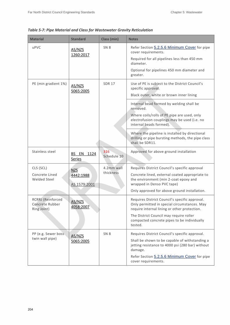
Far North District Council Engineering Standards Chapter 5: Wastewater
204
Table 5-7: Pipe Material and Class for Wastewater Gravity Reticulation
Material Standard Class (min) Notes
uPVC AS/NZS 1260:2017
SN 8 Refer Section 5.2.5.6 Minimum Cover for pipe cover requirements.
Required for all pipelines less than 450 mm diameter.
Optional for pipelines 450 mm diameter and greater.
PE (min gradient 1%) AS/NZS 5065:2005
SDR 17 Use of PE is subject to the District Council’s specific approval.
Black outer, white or brown inner lining
Internal bead formed by welding shall be removed.
Where coils/rolls of PE pipe are used, only electrofusion couplings may be used (i.e. no internal beads formed).
Where the pipeline is installed by directional drilling or pipe bursting methods, the pipe class shall be SDR11.
Stainless steel BS EN 1124 Series
316 Schedule 10
Approved for above ground installation
CLS (SCL)
Concrete Lined Welded Steel
NZS 4442:1988
AS 1579:2001
4.2mm wall thickness
Requires District Council’s specific approval
Concrete lined, external coated appropriate to the environment (min 2-coat epoxy and wrapped in Denso PVC tape)
Only approved for above ground installation.
RCRRJ (Reinforced Concrete Rubber Ring Joint)
AS/NZS 4058:2007
Requires District Council’s specific approval. Only permitted in special circumstances. May require internal lining or other protection.
The District Council may require roller compacted concrete pipes to be individually tested.
PP (e.g. Sewer boss twin wall pipe)
AS/NZS 5065:2005
SN 8 Requires District Council’s specific approval.
Shall be shown to be capable of withstanding a jetting resistance to 4000 psi (280 bar) without damage.
Refer Section 5.2.5.6 Minimum Cover for pipe cover requirements.

Far North District Council Engineering Standards Chapter 5: Wastewater
205
5.2.8. Ventilation and Odour Control
In urban developments, pipes shall be adequately ventilated within private property. However, there are some situations where vent shafts may be required such as:
a) At pumping stations:
b) At manholes where pumping stations discharge to a gravity pipe: and
c) At entrances and exits to inverted siphons.
In such situations vent shafts shall be installed as per the requirements of WSA 02-2017, and WSA 04-2005 (or any amendments as applicable).
Where a vent shaft is required, the Developer shall assess the potential for odours, and the effects of odours on adjacent dwellings. Odour mitigation shall be provided appropriate to the risk. All ventilation and odour control assessment and design shall be undertaken by an IQP.
Either forced ventilation or passive odour control is acceptable provided it is demonstrated that the proposed odour mitigation system will prevent offensive or objectionable odours from causing an adverse effect to adjacent property.
Where fan forced ventilation is proposed for pump station wet wells, it shall provide a minimum of four air changes per hour, and the vent discharge shall be a minimum of 3.6 m high.
5.2.9. Manholes and Inspection Chambers
5.2.9.1 General Requirements
Maintenance structures shall be provided for access and maintenance of the network, including water jetting and video inspections. Preference will be given to structures that will minimise the potential for infiltration. Types of maintenance structures considered are:
a) Manhole,
b) Inspection chamber / mini-manhole (minimum diameter 600 mm), and
c) Rodding eye.
Maintenance structures shall be located:
a) On District Council property or Transport Corridors whenever practicable, preferably located within the berm at 2m offset from the kerb:
b) Out of hollows, dips or any area that may be subjected to inundation or identified as a secondary flow path:
c) Clear of all boundary lines by at least 2m from the outer edge of the manhole chamber plus the height of any nearby retaining walls if they exist:
d) 2m clear of new structures in private property (as shown in FNDC Policy #- Building Over or near Public Sewers and Stormwater Pipelines):
e) In areas that are foreseeably safe to access for the long term:
f) Flush with the adjacent ground level, subject to specific requirements (below) in f lood areas.

Far North District Council Engineering Standards Chapter 5: Wastewater
206
If maintenance structures shall be located in areas subject to flooding, subject to council approval. all components shall be water tight, tied or fixed together, and covers shall be set 300mm above the 1% AEP flood level.
Maintenance structures are required at locations in accordance with Table 5-8 below:
Table 5-8: Maintenance Structure Requirements
Maintenance Structure Locations
Acceptable Option
Manhole Inspection Chamber
(IC)
Rodding Eye
(RE)
Intersection of pipes except for junctions between mains and lateral connections
Yes No No
Changes of pipe grade, except where vertical curves are permitted Yes
For DN150 pipe only using pre-fabricated
vertical bend No
Change of pipe grade at different invert level
Changes of pipe invert level
Yes No No
Changes of pipe size Yes No No
Changes in horizontal direction
Combined changes of pipe direction and grade, except where compound curves are permitted
Yes Use prefabricated
units or bends, max 33° deflection
No
Changes of pipe material, except for repair/maintenance locations
Yes No No
Upstream permanent ends of reticulation
Yes Yes Yes
Discharge of a pressure main into a gravity pipe
Yes No No
5.2.9.1.1. Additional Requirements for Manholes and Inspection Chambers
For infill developments (subject to the restrictions in Section 5.2.10.3 Connection to Trunk and
Interceptor Pipelines), manholes are not required at 150 mm branch connections onto 150 mm mains provided that:
a) a manhole exists on the main within 100 m of the connection point: and,
b) an ‘off-line’ manhole is provided on the branch upstream of the connection point: and,
c) the ‘off-line’ manhole is immediately within the boundary of the property being served (subject to access requirements) or within 20 m of the connection point, whichever is the lesser.
Where public manholes are located on private property, the provisions of Section 5.2.5.2
Reticulation on Private Property shall apply.

Far North District Council Engineering Standards Chapter 5: Wastewater
207
Manholes are the only option where personnel entry is required.
Inspection chambers 600mm diameter are permitted for depth not exceeding 1.2m to invert.
5.2.9.1.2. Additional Requirements for Rodding Eyes
Rodding eyes shall be provided at the end of 100 mm diameter laterals of lengths up to 25 m. For lateral lengths exceeding 25 m, normal requirements apply (i.e. terminating manhole or inspection chamber).
A single lot connection may be made to a rodding eye if required at the terminal end of a lateral.
5.2.9.2 Spacing
Maximum spacing shall be as follows:
a) The maximum distance between any two consecutive maintenance structures shall be 120m.
b) Where a combination of manholes and inspection chambers are used on the same pipeline, the maximum spacing between consecutive manholes shal l not exceed 400m irrespective of the number of maintenance shafts between the manholes
5.2.9.3 Allowable Deflection through Manholes
A maximum allowable deflection through a manhole for pipe sizes 150 to 225DN is 90 degrees. The maximum allowable deflection for pipe sizes greater than DN225 is 110 degrees.
5.2.9.4 Internal Fall through Manholes
The minimum internal fall through a manhole joining main inlet and outlet pipes with the same diameter shall comply with Table 5-9 below:
Table 5-9: Fall Through Manholes
Deflection Angle at Manhole Minimum Internal Fall (mm)
0 - 45 50
>45 - 90 80
Where pipe sizes change at the manhole, the soffit of the inlet pipe should be at least as high as the soffit of the outlet pipe.
Where the minimum internal fall specified above cannot be achieved, e.g. on gradient constrained pipelines, then Specific Design is required.
Effect of Steep Grades on Manholes
To avoid excessively deep channels within manholes, steep grades (> 7%) shall be 'graded-out’ at the design phase.
Where this is not practicable the following precautions shall be taken:
a) The steep grade of an inlet pipe shall be continuous through the manhole,
b) The minimum depth to invert of the manhole shall be 1.5m for DN 150 and DN 225 pipes,
c) The minimum depth to invert of the manhole shall be 2.0m for DN 300 pipes,
d) Vertical change of direction at the manhole not to exceed 45°,

Far North District Council Engineering Standards Chapter 5: Wastewater
208
e) No drop junctions or verticals shall be incorporated in the manhole,
f) Inside radius of channel in the manhole shall be greater than 6 times the pipe diameter, and
g) Benching shall be taken to 150mm above the top of the inlet pipe.
Note: For further guidance on handling steep grades, see WSA 02-2017.
Grading the channel shall be limited to a maximum fall through the manhole of 150 mm.
Where grading the channel cannot be achieved, then a drop connection shall be provided in accordance with section 5.2.9.9 Connections to Manholes.
5.2.9.5 Size of Manholes
Manholes shall be a minimum of 1050mm diameter for depths of 1.0m or more.
5.2.9.6 Materials and Parameters
Pre-cast concrete manholes with external flanged base are acceptable provided that:
They shall be installed in accordance with Sheet 39,
Manholes up to 2.4m deep shall be constructed using a single riser with a pre-cast external flange base:
Manholes in excess of 2.4m deep shall be constructed using a 2.4m deep pre-cast riser with external flange base, and then completed to final ground level using no more than a single riser for manholes up to 5.0m deep. Three risers are allowable for manholes in excess of 5.0m depth:
In no case shall a series of short risers be used:
The joints of all abutting units shall be sealed against ingress of water:
The cover frame shall be set over the opening and adjusted to the correct height and slope using adjustment rings and mortar so as to conform to the surrounding surface:
The cover frame shall be held in place with concrete haunching in accordance with Sheet 39.
Manholes constructed and installed using alternative materials and methodologies shall be in accordance with FNDC Approved Materials List - Wastewater and Stormwater and installation details.
The receiving manhole for discharge from a pressure main into a gravity pipe shall be corrosion resistant and be assessed for ventilation/odour requirements (refer section 5.2.8 Ventilation and
Odour Control).
5.2.9.7 Manholes Requiring Specific Design
Specific Design of manholes shall be undertaken by an IQP and Appendix C ES – PS1 or approved alternative certification provided.
Where manholes are more than 5.0m deep they shall be specifically designed in accordance with the manufacturer’s requirements for external pressures and to resist floatation.
The manhole foundation shall be able to support all design loads placed on it for the duration of the lifecycle of the manhole (and pipeline) it supports. Where the foundation soil may not provide

Far North District Council Engineering Standards Chapter 5: Wastewater
209
adequate support for the pipe, the manhole foundation and associated pipelines shall be specifically designed to prevent damage from practicable ground movement. Acceptable methods include:
a) Use of geotextile fabric:
b) Cement stabilisation: or
c) Removal of unsuitable material and replacement with compacted selected material.
In areas of high-water table, all manholes shall be specifically designed to provide a factor of safety against flotation of 1.25.
Reinforced concrete manholes in suspected or proven aggressive ground conditions shall be specifically designed.
Manholes utilizing materials other than reinforced concrete shall be specifically designed when installation conditions fall outside of the manufacturer’s recommendations.
5.2.9.8 Flotation
In areas of known or practicable high-water table, all manholes shall be designed to provide a factor of safety against flotation of 1.25.
5.2.9.9 Connections to Manholes
The invert of a la tera l connection shall connect to the manhole at a level no lower than the average of the soffit levels of the main inlet and outlet pipes.
Maximum angle of deflection of lateral connection into the manhole main channel shall be 90 degrees.
Drop connections at manholes shall be designed as follows:
a) The drop connection shall be constructed as detailed in Sheet 39,
b) Internal drop connections shall only be constructed in a 1200mm or greater diameter manhole,
c) External drops will not be approved,
d) The minimum height for drop connections shall be 600mm, and
e) Only one drop connection per manhole is permitted.
5.2.9.10 Covers
Watertight manhole covers with a minimum clear opening of 600mm in diameter, complying with AS 3996:2006, and included on the FNDC Approved Materials List - Wastewater and Stormwater shall be used.
‘Non-rock’ covers shall be used on all State Highway and Level 2 roads (roads with greater than 10,000 vehicles per day).
Hinged covers shall be used in all other areas and shall be oriented with the lid folding flat in the direction of traffic flow.
Bolted down covers shall not be used unless there is a possibility of surcharging.
Class D covers to AS 3996:2006 shall be used in the Transport Corridor, carriageway, commercial and industrial properties and all public areas.

Far North District Council Engineering Standards Chapter 5: Wastewater
210
Class B and Class C covers to AS 3996:2006 shall only be used on residential properties.
5.2.9.11 Manhole Steps
All manholes deeper than 1.0m shall be provided with step irons or steps in order to provide access. These shall be of the ‘dropper’ or ‘safety’ type to prevent feet sliding sideways off them.
Manhole steps shall be provided in accordance with Sheet 39 and Sheet 40.
Manhole steps shall be provided at 300mm centers vertically. The top step shall not be more than 450mm below the top of the top slab, and the lowest step shall be not more than 375mm above the bench, or such lower level if detailed on other than standard manholes.
The manhole steps shall be located over the downstream pipe.
5.2.10. Connections
5.2.10.1 General Requirements
Before connecting to the public wastewater system, the District Council’s Public Utility connection process shall be completed by the Developer and the District Council’s approval obtained. This applies to all:
a) New service connections and disconnections from private property:
b) Connections of new wastewater reticulation to the existing public wastewater system:
c) Connections where trade waste will be discharged, and compliance with the FNDC Trade Waste Bylaw 2009 is required.
The lateral connection shall be designed to suit the existing situation and any future development.
The lateral shall be positioned so that the private section of the connection with each lot can be constructed in accordance with the Building Act 2004. This should be at the lowest location in the lot.
Lateral connections may be made to any maintenance structure, or at any point along a main using a proprietary junction, subject to the requirements of Section 5.2.9.9 Connections to Manholes.
Lot connections shall be made directly to the maintenance structure where practicable.
5.2.10.2 Design Criteria
The following design requirements shall be met:
a) The minimum sizes of lateral connections shall be in accordance with Table 5-10.
b) Each connection shall be capable of serving the whole of the lot by gravity, allowing for minimum pipe gradients within the lot (see Table 5-5), and allowing for depth required for gully traps.
c) The standard depth of a new connection at the boundary is 1.2m (range 0.9 - 1.5m).
d) Where the depth of a connection at the boundary is deeper than 1.2m, the service pipe shall be extended into the property on grade, or by use of a ramped riser, to the extent that its terminal end is no deeper than 1.2m.
e) Where practicable, connections should be made directly to manholes.

Far North District Council Engineering Standards Chapter 5: Wastewater
211
f) Connections which shall be made directly to the line shall be designed using a prefabricated ‘wye’ or ‘London Junction’ and shall be watertight.
g) Connections should enter each lot from the road frontage. Where a property has no road frontage, pipes shall be located within that property's legal access (right of way).
h) Where practicable:
i. Private pipes shall not cross property boundaries
ii. Existing private connections crossing boundaries shall be replaced by a public connection.
Table 5-10: Minimum Pipe Sizes for Property Connections
Pipe Minimum Size ID (mm)
Connection serving 1 household unit UNLESS the District Council requires a larger size connection to be provided
Connection to in-fill development, serving up to 3 household units, via an inspection chamber (subject to District Council specific approval)
DN 100
Connection serving more than 1 household unit
Connection serving commercial and industrial lots DN 150
Pipe size shall not be reduced on any downstream section.
Note: See FNDC Wastewater Bylaw 2018 for details of points of discharge with a range of property ownerships and public and private sewer locations.
5.2.10.3 Connection to Trunk and Interceptor Pipelines
Connections to wastewater trunk pipelines shall be at manholes.
A reticulated pipe connection to a wastewater interceptor shall only be designed in conjunction with Council. No individual lot connections are permitted into an interceptor.
5.2.10.4 Connections to Deep Lines
Where an existing or proposed wastewater pipe is more than 5.0m deep to the top of the pipe, or where required by the ground conditions, a manhole shall be constructed on the shallower line. This should be 5m from the deep line and ramped down to it.
5.2.11. Building Over or Adjacent to Pipelines
The following is not permitted without the District Council’s specific approval (refer to FNDC Wastewater Drainage Bylaw 2018):
e) Building over or within a horizontal distance of 2m measured from the outside of pipe:
f) Building within the zone of influence of the pipe:
g) Building within 2m horizontally of the outside of any maintenance structure (manholes, lampholes, maintenance shafts and sewer dead ends):
Far North District Council Engineering Standards Chapter 5: Wastewater
212
h) Driven piles shall not be installed closer than 5m from any pipe unless documentation is provided to the District Council’s satisfaction showing that the proposed works will not damage the asset.
Refer to FNDC Wastewater Drainage Bylaw 2018 for dispensation procedures.
5.2.12. Pump Stations
5.2.12.1 General Requirements
Pump stations in a gravity reticulation system, shall only be approved if it is demonstrated that a gravity connection is not practicable, and that the pump station is the most practicable option.
The following requirements shall apply for public pump stations:
a) Pump stations (and rising mains, refer Section 5.2.13 Rising Mains) shall be designed by an IQP and require Council’s specific approval:
b) Pump stations shall be provided with all-weather vehicle access and provision for parking and maneuvering of maintenance vehicles:
c) Public pump stations and associated vehicular access shall be located within a separate lot vested in Council:
d) Temporary pump stations may be located within an easement registered in favour of Council, rather than a separate lot:
e) Pump stations and associated vehicle access shall not be located where they may adversely affect pedestrian or vehicular traffic:
f) The District Council’s specific approval is required for pump stations proposed within road or public reserves:
g) Valve and pump station lids shall be kept clear of carriageways, footpaths and driveway locations:
h) Modular package pump Stations constructed of GRP or PE, which comply with the ES, shall be used unless site conditions or Specific Design requirements preclude their use:
i) Only Council approved pump station bases shall be used in accordance with FNDC Approved Materials List - Wastewater and Stormwater.
j) Electrical and control systems shall comply with the General Water and Wastewater Specification and FNW Pump Station Electrical Design and Wastewater Pump Station Electrical Engineering Standard.
k) Fencing around the pump station may be required.
Note: Pump stations serving less than six household equivalents shall not be taken over by the District Council.
5.2.12.2 Design Criteria
Pump stations shall meet the following criteria (refer to Sheet 42):
a) Consist of an underground pump well, a separate valve chamber that can drain into the pump chamber, emergency storage, a water supply and electrical control cabinet.

Far North District Council Engineering Standards Chapter 5: Wastewater
213
b) Designed for all imposed loads, including floatation.
c) Designed to ensure that no stormwater enters either through the wall or the roof and lid.
d) Lids and the electrical control cabinet shall be a minimum of 150mm above the adjacent ground level, with the surrounding ground graded away from the station.
e) Located free of secondary flow paths for 1% AEP flood level, and the pump station lid levels shall be provided with a minimum freeboard of 300mm above the estimated 1% AEP flood level.
f) The bottom of the control cabinet shall be provided with a minimum freeboard of 450mm above the estimated 1% AEP flood level.
g) Pump wet well, valve chambers and storage chambers shall have sealed, lockable lids and safety grills that are in accordance with FNDC Approved Materials List - Wastewater and Stormwater and can be readily opened by one person. Openings shall be a minimum of 900 x 900mm.
h) All lifting chains, guide rails, fittings, connections, nuts, bolts etc. in the pump station shall be 314 stainless steel.
i) Pump chamber pipe work shall be stainless steel (316) or fiberglass.
j) Concrete in pump stations shall be suitable for sewer pump stations and shall be lined with an epoxy or similar lining. The concrete strength, admixtures and lining specification shall be supplied in the design submission.
k) Pump impellors shall be hard iron. Impellor types shall be;
i. For rising main diameters of 90mm or greater - an Open Self Cleansing channel impeller. Shredded single or multichannel impellers shall be capable of passing a 75mm diameter solid.
ii. For rising main diameters of less than 90mm - grinder cutter pumps shall be used.
l) The pumping system shall:
i. Have a minimum of two pumps (duty and standby) in all pump stations, with automatic changeover of the pumps if the duty pump blocks or breaks down,
ii. Each pump shall be capable of discharging the design peak wet weather flow rate from the catchment
iii. Include sufficient well volume to operate under normal conditions without surcharge to the incoming wastewater network
m) Access to pump stations shall be suitable for vehicles with a lifting gantry to install or remove pumps and equipment.
n) Float cables and lifting chains shall have hook plates.
o) Non-return and isolating valves for each pump shall be located in the valve chamber. The isolating valve shall be a resilient seated gate valve complying with AS/NZS 2638.2:2011

Far North District Council Engineering Standards Chapter 5: Wastewater
214
(anticlockwise closing) installed downstream of the non-return valve. Non-return valves shall be ball-valves with full-bore opening or swing check valves with external handles.
p) The capacity of the wet-well between start and stop levels shall be such as to limit pump starts to no more than fifteen per hour.
q) Pump Stations shall have emergency storage in case of mechanical or electrical failure or blockage of the pumps or rising main. The storage shall be located at such a level as to prevent overflow from any manholes, gully traps, pump station lids or any other outlet from the system. Storage tanks shall be provided with a lockable, hinged, water tight lid with a minimum opening of 900 x 900mm, and able to be opened by one person by hand.
r) Pump stations and rising mains shall be designed to provide for the peak wet weather flow from the ultimate catchment development, without utilising the required emergency storage capacity.
s) Variable speed drive is required for pumps over 5kW.
t) Shielded power supply cables are required on all pumps exceeding 5kW.
u) All pump stations shall be reviewed for the potential for odours in accordance with the section on Ventilation and Odour control
v) The electrical supply shall be underground.
w) Lighting shall be provided to illuminate the control cabinet. A 10A single phase power socket shall be provided in the cabinet with RCD protection.
x) Suitable low maintenance landscaping may be required on the pump station site around the wet well area.
y) Fencing may be required where the pump station is exposed to traffic etc.
z) An Operating and Maintenance Manual shall be provided that covers all aspects of the design and operation of the stations including:
i. Design calculations, including pipe and fitting head-loss assumptions and pump curves
ii. A plan of the design catchment
iii. As-Built Plans including circuit diagrams and switch locations
iv. Pump details, pump duty information, float switch levels
v. Contingency measures for emergency overflows
vi. Operation and maintenance procedures
vii. Other relevant data and information.
viii. Guarantees and warrantees
aa) Pump stations shall be tested and commissioned in the presence of a Council representative strictly in accordance with the General Water and Wastewater Specification and FNW Pump Station Electrical Design FNDC Wastewater Pump Stations Electrical Engineering Standards and FNDC QA/QC Manual 2020??

Far North District Council Engineering Standards Chapter 5: Wastewater
215
5.2.12.3 Pump Station Sizing
5.2.12.3.1. Pump Stations
Pump stations shall provide pumping velocities in the rising main in the range 0.6 to 2.5m per second.
Where practicable, the rising main should be sized, and the pump controlled, such that the volume of the rising main is pumped at least once each day, preferably each pump cycle. If there is insufficient inflow into the pump station to achieve this, then odour measures shall be incorporated into the design unless the results of a ventilation and odour control assessment (see Section xx) demonstrate that these are not required.
Where the pump station discharges into a common pressurised main that is used by other pump stations, variation in head conditions caused by the operation of the other stations shall be taken into account. Supporting information shall be provided to demonstrate satisfactory operation of the network for all pumping scenarios.
A pump station design shall document the effluent volumes and associated pump requirements for the fully developed catchment and at commencement of operation.
The calculation of flow shall follow the design criteria in Section 5.2.4 Design Criteria. These projections will be described as
a) Average Dry Weather Flow:
b) Peak Dry Weather Flow:
c) Peak Wet Weather Flow:
d) Peak Daily Flow.
If the station catchment shall be fed by other pumping stations then these flows shall be calculated both for the direct gravity catchment as well as direct plus contributing catchment.
All calculations shall be submitted to the District Council for approval and all assumptions, design variables etc. shall be clearly documented.
5.2.12.3.2. Flow Meter Sizing
Pump stations with an ultimate design flow of 10 l/sec or greater shall be provided with magnetic flow meters on the rising main, connected to Council’s telemetry system. The system shall record instantaneous flow and totalised flows.
The flow meter shall be from FNDC Approved Materials List - Wastewater and Stormwater potted for IP68 which is required to be factory ‘Finger printed’ and appropriately sized for the rising main.
The Pump Station design shall ensure the flow meter is fully charged during non-pump operation.
The transmitter shall be located in the cabinet with analogue and digital information connected to the Council’s telemetry system.
Where the meter is positioned within the designated site and free of roading or concrete cover then the meter may be buried or otherwise housed within a 1,050 manhole with 400mm clear of the invert of the meter. Both installation types are to connect to the cabinet by ducting. Where buried the end of the duct shall be sealed to prevent ingress of soil and moisture.
5.2.12.4 Layout and Access
The site shall be laid out to comply with Sheet 41.

Far North District Council Engineering Standards Chapter 5: Wastewater
216
The alignment of the pump station shall be set out with reference to permanent land transfer pegs or temporary boundary marks, placed by the licensed cadastral surveyor responsible for the final land transfer pegging.
The site design shall include a paved all-weather access road with a minimum width of 3.5m. The centre line of the parking space shall be no greater than 4.0m in plan from the distal pump and no greater than a 0.5 m difference in elevation between the parking area and lid elevation.
Where the access way is longer than 30m, a turning point for a light commercial vehicle shall be provided at the well. The gradient of the access way shall not exceed 1 in 6, and all turning radii comply with light truck tracking curves.
The control cabinet shall be located with the switch gear facing the wet well and placed no closer than 2.5m to any well or valve chamber lids and no further than 5.0m. This is to provide safe working room between an open lid and the cabinet.
The above ground structures, including but not limited to control cabinet, odour control and RPZ, shall be positioned such that any ‘out of control’ vehicles leaving surrounding public roadways are unlikely to damage these structures. Protection such as guardrail or posts and rails may be required.
An area of 5.0 x 5.0m shall be available to accommodate an odour biofilter, either at the time of construction or in the future.
5.2.12.5 Pump Station Inlet
The floor of the pumping station shall be set at such a level below the inlet pipe so that the inlet pipe will not surcharge during the normal pump operation cycle, which includes standby pump operation.
5.2.12.6 Wet Well
5.2.12.6.1. Diameter
The minimum diameter of the pump chamber shall meet both the minimum separation distances of the pump supplier, and provide sufficient operational capacity to meet the maximum number of starts per hour (refer Section 5.2.12.2 Design Criteria) but be no less than 1.8m deep.
5.2.12.6.2. Depth
Sufficient depth shall be provided in the pump chamber such that:
a) For a gravity inlet pipe, the inlet shall have a minimum of 100mm free board to surcharge during operation of the duty pump,
b) For a rising main inlet, the inlet shall be below the pump stop level,
c) The minimum distance between duty pump start and stops levels is 400mm, and
d) The design stop level is 50mm above the pump manufacturer’s minimum continuous operating levels.
5.2.12.6.3. Structural Stability
The pump station wet well shall be designed to have negative or zero buoyancy. Accordingly, the chamber may require mass concrete in the bottom to counter buoyancy forces. The depth and extent of mass concrete shall be as specified on the Engineering Plans.
The ground water level shall be assumed to be at ground level unless an actual level is established by geotechnical investigation and approved as suitable for this purpose by the Council.

Far North District Council Engineering Standards Chapter 5: Wastewater
217
The mass of the wet well structure included in the stability analysis shall not include the associated mechanical and electrical components of the pump station nor can the soil friction forces of backfill around the wet well chamber be taken into account. The proposed pump station drawings shall provide dimensions of the extent of mass concrete needed to counter buoyancy of the chamber.
Foundation design of wet wells requires Specific Design by an IQP in accordance with the design considerations in Section 5.2.9.7 Manholes Requiring Specific Design.
5.2.12.6.4. Valve Chamber
The valve chamber shall be attached to the pumping chamber. Where the delivery point is within close proximity to the pumping station the valve chamber may be dispensed with and a separate rising main from each pump laid to the delivery point. Where this occurs land shall be allocated for a valve chamber to cater for any future operational changes.
The layout of the pumping chamber, valve chamber and pipe work be similar to that shown on Sheet 42 and Sheet 41.
5.2.12.6.5. Lids
Lids shall be of a standard design as per the FNDC Approved Materials List - Wastewater and Stormwater.
For any well or chamber where the depth is greater than 2.0m secondary lids are required to satisfy health and safety requirements.
5.2.12.7 Emergency Storage
See also 5.2.12.8 Compliance with the NRC Regional Plan for Northland.
Pump stations shall provide for wastewater storage in the event of pump failure through electricity outage.
5.2.12.7.1. Sizing
A minimum of 4 hours emergency storage based on average dry weather flow, or minimum specified in the NRC Regional Plan (whichever is greater) shall be provided prior to emergency overflow occurring. The storage volume should be measured between the high-level alarm and the point of overflow.
The required storage volume shall be provided by:
a) The volume of the wet well: plus
b) Any additional ancillary storage chambers.
The wet well volume below the high-level alarm level shall be excluded from the calculation of available storage volume.
5.2.12.7.2. Layout
A site-specific layout design is required.
Preferably the storage volume shall be provided in the pumping wet well structure and upstream pipelines.
Any pipe or chamber (whose sole purpose is for the provision of storage capacity) can be connected directly into the pump chamber. It shall be benched such as to direct all flow to the outlet point.
For all other sole purpose storage facilities, the benching shall be at a minimum gradient of 1 in 3 to allow self-draining. A central channel within the storage well shall be at a minimum of 1% gradient.
Far North District Council Engineering Standards Chapter 5: Wastewater
218
If the storage chamber is provided with an automated wash down facility following storage use the minimum grade can be reduced to 0.15%.
Where storage is developed within the upstream pipework and carries wastewater flow, these structures shall have the haunching constructed to cater for the normal operation, with a seamless progression to the haunching required for the free drainage post emergency.
5.2.12.7.3. Structural Stability
The foundation and buoyancy of the storage chambers shall be determined and designed for as per the methods used for the wet well, refer section 5.2.12.6 Wet Well.
5.2.12.8 Compliance with the NRC Regional Plan for Northland
Pump stations shall comply with the requirements for a controlled activity in the Rules for Sewage Discharges in the Northland Regional Plan, and any necessary resource consents for its installation and use shall first be obtained by the Developer.
Note: Where particular constraints exist – e.g. a sensitive receiving environment such as a bathing area or marine farm, the consent conditions may require a greater storage capacity.
5.2.12.9 Electrical and Control
The Developer shall determine adequacy of any existing supply and arrange for the power supply to a pump station. The power supply for public pump stations shall be transferred to Council following successful testing and commissioning of the pump station.
The electrical switch box shall be located in a safe position as close as practicable to the pump chamber. It shall be fabricated from Aluminium or Stainless Steel, or Aluminium Montrose type. Vents etc. should be incorporated in telemetry masts.
The electrical and control system shall strictly comply with the General Water and Wastewater Specification and FNW Pump Station Electrical Design and FNDC Waste Water Pump Stations Electrical Engineering Standard
.
5.2.12.10 Telemetry
All pump stations and treatment facilities shall be connected to Council’s telemetry system. Council shall confirm whether satisfactory radio network communications are available at the site. If not, an alternative communication system (e.g. telephone landline with autodialer, or cell phone) shall be provided.
5.2.12.11 Water Supply
Where a Council reticulated water supply is available, fresh water shall be supplied from a standard 25mm. ID connection at a minimum static pressure of 250kPa. A standard hose connection shall be fitted.
If the water supply is taken from Council’s drinking water network, backflow prevention shall be provided in accordance with the NZ Building Code Approved Documents for a high-hazard installation (RPZD) and Sheet 44.
The backflow preventer shall be positioned next to the electrical control cabinet and the water connection outlet shall terminate in the pump chamber.
Far North District Council Engineering Standards Chapter 5: Wastewater
219
The Developer shall apply to the District Council for the connection (including the meter and backflow preventer), pay all costs and provide as-built details including all requirements of Section 6.1.7 Connection to Existing Water Supply System.
5.2.12.12 Pump Design
5.2.12.12.1. Pump Selection
Pumps shall be three phase submersible type design selected, from Council’s FNDC Approved Materials List - Wastewater and Stormwater, to achieve the pump station design criteria in Section 5.2.12.2 Design Criteria.
Pump jackets shall be stainless steel.
The pumps shall be connected by way of a ‘duck foot’ discharge pedestal to enable the removal and manipulation of the pump from the top of the wet well.
In selecting the appropriate pump(s) the operating conditions shall correspond as closely as practicable to the point of maximum pump efficiency. Final pump selection shall be approved by the District Council in order to facilitate standardisation of pump model and impellor sizes.
In calculating the system head losses, allowances shall be made for all bends and fittings beyond the pump discharge bend together with the rising main friction losses.
The system static head shall be based on the difference in level between the centreline of the inlet face for the pump discharge bend and the highest point on the rising main system.
The rising main system curve shall be modelled using the Colebrook White formula. Calculations of friction loss should be carried out based on roughness ‘k’ values of 1.5m and 0.5mm to ensure that the selected pump is capable of operating over this range of duty points.
5.2.12.12.2. Risers and Valve Sizing
The pumpset riser is defined as all pipework between the discharge bend to the inlet of the rising main isolation valve.
Internal pipework for each pumpset shall be at a minimum of that determined by the pump discharge bend. Where there is a difference in the size between the discharge bend and subsequent steelwork the reducer shall be immediately post discharge bend and/or prior to isolation valve if needed.
The valve installed along the pump set riser shall be of a similar dimension to the pipework.
Isolation valves for each pump set shall be of a quarter turn eccentric plug type with ability to lock in either open or close position using a standard padlock.
5.2.12.12.3. Non-Return Valves
The installation of a non-return valve on each pump set is required to ensure the pumps are protected from reverse flow and that flow from a pump is not returned to the well through the standby pump reducing operational capacity.
Where the dynamic head for a pump is less than 15m, as measured at the location of the non-return valve, a ball type valve can be used. For those stations that experience levels greater than 15m a resilient seated rubber flap check valve shall be used. Flap check valves shall be installed with an external indicator arm.
For those stations where the total head is above 30m a detailed engineering design solution shall be provided showing the limitations on the system for water hammer following the controlled shutdown of pumps (excluding power failure).
Far North District Council Engineering Standards Chapter 5: Wastewater
220
5.2.12.13 Private Pump Stations
Private pump stations are permitted where it is not practicable or economic to provide a gravity connection to a public sewer. A proprietary packaged pump station, with grinder pumps, shall be used and shall comply with the NZ Building Code. Private pump stations will not be accepted as vested assets.
5.2.13. Rising Mains
5.2.13.1 General Requirements
Rising main design shall be undertaken by an IQP, and fully account for the characteristics of the system in question including pump characteristics, surge, flow regimes and fatigue.
The design shall minimise the time wastewater spends in a rising main, to avoid septicity and odour problems, and maintain self-cleansing velocities.
The rising main shall be designed to withstand normal operating pressures, including short duration surge pressures from normal cycling and special events (such as power failure).
The rising main shall be designed for connection to a District Council approved location on the existing wastewater network.
The District Council may specify the diameters and classes of pipes to be used and the alignment of the rising main.
Designers shall consider the hydraulic adequacy of the network including the specified levels of service and impact on the existing network.
For design purposes, and subject to availability, the District Council may:
a) provide details of the working pressure of the existing network, or of pressures at the approved connection point, and
b) provide details of the capacity of existing network.
Where this information is not available from District Council records, or further information is required for the design, the Developer shall consult with the District Council regarding the completion of any investigations.
The Developer shall generally cover the cost of investigations required to complete their design to this standard.
5.2.13.2 Scope of Design
The scope of design shall include:
a) Pipe sizes, material, and layout of the rising main,
b) Hydraulic design,
c) Service connection locations,
d) Types and locations of valves and other similar control devices
e) Thrust blocks and anchors (where applicable),
f) Pipe cover and protection appropriate to expected loading,

Far North District Council Engineering Standards Chapter 5: Wastewater
221
g) Bedding and backfill, and any specific installation requirements (e.g. pipe anchors/bulkheads), and
h) Preparation of construction specifications.
i) Design drawings shall comply with the requirements of Section 1.5.3.3.5 Design Statements
and Engineering Plans and Appendix G Drawing Standards:
5.2.13.3 Maximum Operating Pressure
The components of a pressure pipeline shall be designed to withstand a maximum operating pressure that is greater the following:
a) 400kPa (note that this is not the minimum pipeline pressure class),
b) 1.5 x (static head + friction head),
c) Pump shut off head,
d) Positive or negative surge pressures.
External loads on the pipeline shall be included in all load cases, especially when pressure testing large diameter pipes. A factor of safety of at least 2 against buckling under negative or external pressures shall be allowed for. All fittings shall have a pressure rating equal to or greater than the pressure rating of the associated pipeline, or PN12, whichever is the greater.
For plastic pipes, fatigue during service may require that a higher nominal pressure rating is specified, which shall be the greatest of the following:
a) The maximum calculated operating pressure,
b) The equivalent operating pressure based on a surge & fatigue analysis.
To calculate the equivalent operating pressure (Peo) the methodology described in Appendix A
Design for Surge and Fatigue shall be used.
5.2.13.4 Pressure Surges
Design for pressure surge in pump rising mains shall be undertaken by an IQP in accordance with the principles detailed in Appendix A Design for Surge and Fatigue.
In addition to the considerations in Appendix A Design for Surge and Fatigue, the designer shall also consider:
a) Soft closing, non-return valves for installations in high head situations as well as variable speed controls:
b) Allowance for Operation and Maintenance requirements:
c) Failure of any mechanical surge protection measures and protection from damage during these situations.
5.2.13.5 Pipe Sizes
Pipe sizes shall be suitable for the design.
Pipe diameters shall be limited to the following standard sizes: 50mm, 100mm, 150mm, 200mm, and 300mm nominal bore (internal diameter). Council’s specific approval is required for pipe sizes exceeding 150 mm.

Far North District Council Engineering Standards Chapter 5: Wastewater
222
5.2.13.6 Velocity
Pressure mains shall have an absolute minimum velocity of 0.75 m/s, and a maximum velocity of 2.5 m/s.
The preferred velocity range is 0.8 m/s to 1.2 m/s. Velocity shall be confirmed in the design submission.
5.2.13.7 Gradients
The profile of rising mains shall be designed to minimise the number of high and low points, which require the installation of air and scour valves respectively. The final profile will be a balance between the minimum depth of main and number of valves.
Rising mains shall be graded continually upwards from the pumping station to termination. Design to keep the pipe full and prevent sudden discharges of foul air at pump start.
If a summit is unavoidable;
a) automatic air release valves shall be provided,
b) air valves shall be design specifically for wastewater operation
c) air valves shall be mounted vertically above the pipeline to which the air valve is connected.
d) an isolating gate valve shall be fitted between the air valve and the vented pipeline and the valves shall be mounted in a concrete valve chamber.
The valve chamber shall be large enough to allow easy access for maintenance staff to operate the isolating valves, or remove all valves from the chamber.
At low points, drain valves and chambers shall be provided such that the contents of the entire main can flow into the chamber and the contents be collected by a sucker truck. Alternatively, it may be practicable to drain directly to a nearby sewer (subject to the District Council’s confirmation of suitability and availability of capacity).
5.2.13.8 Cover over Pressure Pipes
The minimum cover over the top of the pressure pipe to finished ground level shall comply with the requirements of section 5.2.5.6 Minimum Cover.
5.2.13.9 Flanges
All valves and fittings shall be flanged to either AS 2129:2000 Table D/E or AS/NZS 4087:2011 Metallic Flanges for Waterworks Purposes Class 16. It is the Designer’s responsibility to ensure that all mating flanges are compatible.
Note: This also applies to items such as flow meters and check valves
Alternative flange standards (such as ANSI or DIN) will not be approved.
5.2.13.10 Sluice Valves
Sluice valves shall be attached to flanged fittings rather than plain-ended fittings.
The force required to open or shut a manually operated valve, using a standard valve key, with pressure on one side of the valve only, shall not exceed 15 kg on the extremity of the key.
Geared operation, motorised valves or a valve bypass arrangement shall be specified if the allowable force cannot be met, in order to reduce pressure across the valve.

Far North District Council Engineering Standards Chapter 5: Wastewater
223
5.2.13.11 Scour Valves
Scour valves are required on the low point of all rising mains.
Valves shall be the same size as the main, but no greater than 150mm in size.
Scour valves shall be installed at the lowest point between isolating valves, and discharge to an approved chamber.
5.2.13.12 Air Valves
Air can accumulate at high points when it is drawn into the system.
It is preferred not to have any high points in wastewater rising mains. If this cannot be achieved, mains should be laid evenly to grade between peaks to ensure all practicable locations of potential air pockets are well known.
The need for air valves at all high points shall be investigated, particularly those more than 2m higher than the lower end of the section of main, or if the main has a steep downward slope on the downstream side.
Air may also come out of solution in the wastewater due to a reduction in pressure, such as when wastewater is pumped uphill. Air valves may be required to allow continuous air removal at these locations.
Air valves shall be sized for peak flow rates and located as required for surge protection.
Air valves shall also be located on long horizontal runs at a maximum interval of 800m.
Only air valves on FNDC Approved Materials List - Wastewater and Stormwater shall be used.
5.2.14. Pressure Sewer Systems
5.2.14.1 General Requirements
Several areas within the Far North District are serviced by pressure sewer systems. Pressure sewer systems consist of a small pumping unit installed on each property which pumps sewage into a small diameter pressure pipe network which then discharges either to the downstream gravity sewer network or into a communal pump station. The manner in which the pressure sewer system shall be used or applied in the district is described in the FNDC Pressure Sewer Policy (to be developed) General Water and Wastewater Specification
The design of a pressure sewer system shall be in accordance with WSA 07-2007. References in WSA 07-2007 to the “Water Agency” shall be taken to mean the District Council.
Septic tank effluent pump (STEP) systems are not an approved pressure sewer system. Refer to Section 5.1.5.4 Private Treatment and Disposal for considerations regarding STEP systems.
The following sections cover specific requirements in addition to those set out in WSA 07-2007code, and shall take precedence over the WSA 07-2007.
5.2.14.2 Objectives of the System Design
In addition to those set out in 1.6.2 of WSA 07-2007, the sewer system shall meet the following objectives:
a) All domestic wastewater is catered for:
b) All stormwater is excluded from the sewer system:

Far North District Council Engineering Standards Chapter 5: Wastewater
224
c) Minimum 12 hours of emergency storage is provided within the pumping station.
5.2.14.3 Detailed Design
Pressure sewer detailed design shall be separated into two components, reticulation design and on-property design.
Reticulation design covers the design of the actual pressure sewer system which includes reticulation pressure pipes, laterals, boundary kits and appurtenances (e.g. valves and flushing points). Boundary valve kits shall be installed by the Developer at the time of construction of the pressure sewer reticulation.
On the property design covers the design of the property discharge line, collection tank/pump unit, control/alarm panel and electrical cables. The on-property design takes place sometime after the reticulation has been designed and installed.
Design of pressure sewer systems shall be undertaken by a suitably qualified IQP. The Designer shall confirm their competence in designing this technology.
5.2.14.4 Odour Control
The designer shall consider ventilation and odour control in accordance with Section on Ventilation and Odour Control
The assessment shall include calculations to quantify odour generating potential, and demonstrate how odour generation will be mitigated. The designer will shall liaise closely with the District Council on proposed ventilation and odour control measures.
The designer shall ensure that the sulphide generation potential in pressure sewers that discharge to standard (not corrosion resistant) manholes is kept to a level that is not likely to cause nuisance odour or have a detrimental effect on the existing infrastructure.
5.2.14.5 Design Tolerances
Section 3.2 of WSA 07-2007: Reference to MGA, GDA and AHD is removed.
Survey co-ordinates and levels shall be provided in accordance with Section 1.7.2 As-Built Plans,
Asset Information Schedules, Operation and Maintenance Manuals and Appendix G Drawing
Standards.
5.2.14.6 Environmental Considerations
In addition to meeting these design standards, the Developer’s design shall comply with the requirements of resource consent conditions, archaeological requirements, and district & regional plans.
5.2.14.7 Reticulation Sewer
The sewer reticulation main shall not be constructed through private land.
5.2.14.8 On-property Components
All on-property items shall be located within the property boundary of the property being served.
Easements are generally not required over the property discharge pipeline but the owner is to provide a clear and direct alignment for the discharge pipeline to connect to the reticulation in the street.
Far North District Council Engineering Standards Chapter 5: Wastewater
225
5.2.14.9 Clearance from structures
To enable future maintenance and protect the system, a minimum offset of 2m from any building or structures is required. Refer to (refer to FNDC Policy xxx - Building over Public Sewer and Stormwater Pipelines)
5.2.14.10 Septicity
Calculation of sewage age shall take into account the staging of the development.
5.2.14.11 Design inputs and Outputs
During the Developers design process, the Developer shall confirm with Council the nominated discharge point on the District Councils existing system that the Developer needs to convey sewage to.
5.2.14.12 Sanitary Flows
Sanitary flows shall be determined in accordance with Section 5.2.4 Design Criteria.
5.2.14.13 Infiltration and Inflows
The pumping unit shall be designed to prevent infiltration and inflows. Existing houses will not be connected to the system until all private drains discharging into the system have been inspected and pass the building consent requirements. The pumping unit shall be separated from any stormwater drainage pipes.
5.2.14.14 Peak Flows from Homes and Required Pumping Rates
Swimming pools, spas and other high-water use appliances shall not discharge to the pressure sewer system unless appropriate flow restrictors are installed to ensure the discharge rate does not exceed the capacity of the pump station.
5.2.14.15 Design Flows
The probability design method is an acceptable method for designing grinder systems unless the limitations noted in section 4.4.4.1 of WSA 07-2007 apply.
The Developer’s design submission shall include calculations of the design flows adopted for each pressure sewer line.
5.2.14.16 Minimum Pipe Sizes
Council may direct the Developers designer to increase the diameter of pressure sewers to account for adjoining developments or based on its own operation experience.
5.2.14.17 Alignment of Pressure Sewers
90° bends shall be avoided where practicable. Alternatives include use of 2 x 45° bends or bending the pipe within the manufacturers allowed limit.
5.2.14.18 Boundary Valve Kits
Individual boundary valve kits shall be provided to serve each lot. They shall be installed at the time of construction of the pressure sewer reticulation, and shall be located outside the property boundary unless it is more prudent to locate it inside the property which the unit serves. In all cases the location shall facilitate access to the valves, and shall not be installed in a trafficable area. The boundary kit is to have a bright red coloured lid with the colour homogeneous in the lid material.
Far North District Council Engineering Standards Chapter 5: Wastewater
226
5.2.14.19 Isolation Valve Location
Isolation valves shall be installed at incoming reticulation pressure lines, i.e. at Tees, and one upstream and one downstream of scour valves.
Isolation valves shall be fusion bonded epoxy coated and resilient seated gate valves.
Isolating valves shall be constructed in accordance with the detail in Sheet 49, located in surface boxes, circle lids painted with red colour homogeneous in the lid material. The valve shall also be identified using a grey marker post with letters “SSV” (for “Sewer Sluice Valve”)
5.2.14.20 Air Release and Vacuum Break Valves
Only air release valves authorised by the District Council and listed in the FNDC Approved Materials List - Wastewater and Stormwater shall be used.
In determining the location of the air release valve, the following factors shall be considered:
a) Proximity to properties:
b) Venting requirements:
c) Aesthetics.
5.2.14.21 Chambers
Air release valves shall be in covered concrete chambers so as to provide adequate clearance for servicing/replacement of the valves (Sheet 51).
The chamber shall be adequately vented for effective operation of the valve. Any odour issues associated with the venting shall be addressed in the design.
Air valve shall be identified by a grey marker post, and have a letters "SAV" (for “Sewer Air Valve”).
5.2.14.22 Flow Meters
The District Council shall determine whether flow meters are required and their location.
Where specified, the flow meter shall be design and construction in accordance with Section 5.2.12.3.2 Flow Meter Sizing .
5.2.14.23 Discharge Manholes
Where the receiving manhole is substantially deeper than the normal depth of the pressure main, the pressure main shall be graded out to enter the base of the manhole in such a way that it can discharge directly towards the downstream gravity pipe, minimizing disturbance to flows and the likelihood of creating gases. If grading out the pressure main is not practicable an internal manhole drop shall be designed in such a way that the flow is discharged directly towards the downstream gravity pipe as above.
Where required, venting shall be provided to the receiving manhole.
Consideration shall be given to protecting the receiving structure by, replacing it with corrosion resistant chamber or coating internal exposed surfaces (if approved by the District Council).
The receiving structure should be located as far as practicable from residential properties.
5.2.14.24 On-Property Design
Design Tolerances: WSA 07-2007 Section 6.1.2:

Far North District Council Engineering Standards Chapter 5: Wastewater
227
Reference to MGA, GDA and AHD is removed.
Survey co-ordinates and levels shall be in accordance with Section 1.7.2 As-Built Plans, Asset
Information Schedules, Operation and Maintenance Manuals and Appendix G Drawing
Standards.
5.2.14.25 Vacant Lots
Boundary Kits shall be provided at each vacant lot to facilitate connection of new houses to the system after the pressure network becomes live.
5.2.14.26 Property Discharge Line
Pressure sewer laterals shall only be directly connected to pressure mains that are DN225 or less. Where connection to mains greater than DN225 is necessary, a new pressure main will be required.
5.2.14.27 Collection Tank and Pump Units
Only pumping units (including tank) approved by FNDC Approved Materials List - Wastewater and Stormwater and the associated purchasing specifications shall be used.
5.2.14.28 Pipework and Fittings for Pressure Sewer System
The pressure sewer pipes and fittings shall be constructed using PE100 SDR11 (PN16) suitable for jointing with electrofusion fittings or butt fusion welding. Refer to Section 5.3.5.1 Rising Mains.
The minimum pipe size for reticulation is DN50 (50mm OD).
Property discharge line for a standard house connection is usually DN40 (40mm OD).
Only black polyethylene pipes with off-white (cream) stripe shall be used.

Far North District Council Engineering Standards Chapter 5: Wastewater
228
5.3. Construction
5.3.1. Pipeline Installation
This section covers the installation requirements for all piped wastewater and storm water networks.
The installation of pipelines shall be carried out in accordance with AS/NZS 2566.2:2002 (where applicable) and Sheet 31 and Sheet 32.
Pipe pressure rating of PN16 SDR 11 is required for trenchless construction.
Pipe pressure rating PN12 is acceptable for trenchless construction of rising mains.
5.3.2. Materials
Materials shall be in accordance with the requirements of Section 5.2.7 Approved Materials and FNDC Approved Materials List - Wastewater and Stormwater.
5.3.3. Pipe Installation by Trench
5.3.3.1 Pipe Embedment and Marking
5.3.3.1.1. Embedment
Pipes shall be bedded and protected as specified on the approved drawings. Where not specified on the drawings, bedding and protection shall be in accordance with Sheet 31 and Sheet 32 and the particular manufacturer’s specifications.
The designed trench width shall be sufficient width, (minimum in accordance with Sheet 31), to allow pipes to be safely laid and all embedment material properly and sufficiently compacted.
Embedment and fill shall keep pace with the excavation and laying of pipes so that not more than 15m of pipes shall be left exposed in open trench where this could represent a danger to road users.
The foundation shall be able to support all design loads placed on it for the duration of the lifecycle of the pipeline it supports. Where the bottom of the trench will not provide adequate support for the pipe, the designer shall provide a suitable means to stabilise trench foundation. Acceptable methods include:
a) Use of geotextile fabric:
b) Cement stabilisation: or
c) Removal of unsuitable material and replacement with compacted selected material.
No embedment material shall be placed or pipes laid before the trench foundation has been inspected and approved by Council.
The various zones comprising the embedment depth shall be laid in ascending order. Each zone shall be laid in accordance with the approved design and shall contain the specified selected material compacted to the required density. There shall be no sharp stones or large clay lumps in the bedding or surround.

Far North District Council Engineering Standards Chapter 5: Wastewater
229
Where pipelines have protruding projections such as sockets, flanges or couplings, a suitable recess shall be provided, in the supporting material, to ensure the pipeline is fully supported along the pipe barrels.
Pipes made of plastic materials shall be laid with product labelling uppermost in the trench.
5.3.3.1.2. Pipeline Marking
Detection tape shall be laid directly above all rising mains and above new sewers. The tape shall have ‘sewerage’ written on it in white and be located at a depth of between 200 and 250mm above the pipe crest.
Where the pipe is not laid in a straight line between manholes the tape shall contain sufficient metal to be detectable from the surface by a standard metal detector.
Tracer cable shall also be attached to all pump riser mains and pressure sewer mains. This wire shall take the form of a continuous 2.5mm2 multi strand (polythene sleeved) cable, strapped to the pipe wall by means of a minimum of two complete wraps of heavy-duty adhesive tape, at a maximum of 3.0m intervals.
The tracer cable shall be connected to all surface boxes, and electrically tested for continuity by a Registered Electrician following installation and backfilling. Records of the electrical continuity test shall be provided by the contractor.
5.3.3.2 Tolerances
Pipes shall be accurately laid to the lines, levels and gradients shown on the Drawings using pipe-laying laser equipment.
The permissible deviation of the alignment and gradient of pipelines shall be the lesser of ± 5% of the nominal diameter of the pipe or ± 20mm from a straight line between the inverts of successive manholes, with all such deviations being gradual. There shall be no steps at the junctions between successive pipes and no point in the pipeline shall be lower than any downstream point.
Where the variation exceeds the tolerance Council may order the removal and relaying of any affected pipes.
5.3.3.2.1. Invert Levels
The permissible deviation from the designated level of the invert at each manhole or structure shall be ± 50mm, provided that the fall between successive manholes or structures shall be at least 90% of that specified.
5.3.3.2.2. Horizontal Alignment
The permissible deviation of the horizontal alignment between manholes or structures shall be ± 100mm.
5.3.3.2.3. Gradient
For straight gradients, the permissible deviation from the specified gradient shall be ± 50mm from a straight line drawn between the inverts of successive manholes, provided that no point in the pipeline is lower than any downstream point.

Far North District Council Engineering Standards Chapter 5: Wastewater
230
5.3.3.3 Backfilling and Reinstatement
5.3.3.3.1. General
The trench or embankment fill material and trench reinstatement shall be as specified on the approved drawings. Where not specified on the drawings, fill material and trench reinstatement shall be in accordance with Sheet 31.
Trench or embankment fill shall be compacted in layers to the specified finished level. When compacting in layers the depth of each layer shall be as specified on the approved drawings. Where not specified on the drawings, depths of layers shall be in accordance with Section 5.3.3.3.3
Compaction.
In public areas, backfilling shall keep pace with the laying of pipes so that there is no more than 15m of open trench at any time.
Mechanical compaction of the fill material directly above the pipe shall not be commenced until the depth of cover above the top of the pipe is adequate to prevent damage to the pipe.
Displacement of the laid pipes during backfilling shall be prevented. Compaction equipment which can produce horizontal or vertical earth pressure on the pipeline, which can cause damage or excessive distortion of the pipeline, shall not be used.
The Contractor shall reinstate trenches within 7 days of back fill completion. The surface level of the reinstated trench shall match the surrounding surface level.
All compaction test results shall be submitted to Council for approval.
5.3.3.3.2. Backfill Materials
Except as specified below, selected material excavated from the trench may be used for backfilling trenches. Where reuse of previously excavated material is specified, its selection and use shall be approved by the designer.
In roads and paved areas where material excavated from the trench cannot meet the compaction standards in Section 5.3.3.3.3 Compaction, imported granular material shall be used.
Surplus and unsuitable material from the excavation shall be disposed of at a consented landfill.
5.3.3.3.3. Compaction
Within the Transport Corridor
Trenches in the Transport Corridor, or under private access or paved (vehicular) areas, shall be backfilled and compacted in layers of thickness commensurate with the compaction equipment to a density of at least 95% of the maximum dry density. Field compaction shall be tested as follows:
For cohesive soils - New Zealand standard compaction test, nuclear densometer and shear vane.
For non-cohesive soils - New Zealand standard compaction test, nuclear densometer or dynamic cone penetrometer (Scala Penetrometer).
Testing by other means shall be subject to the approved Inspection and Testing Plan or conditions of Engineering Design Approval.
Compaction testing of sub-base and base course shall be in accordance with requirements 3.3.4
Pavement Testing.

Far North District Council Engineering Standards Chapter 5: Wastewater
231
The designer shall specify a testing regime to verify the compaction effort meets the density specified to support the designed traffic loading.
The Contractor shall undertake tests in accordance with the approved Inspection and Testing Plan or conditions of the Engineering Design Approval, to demonstrate that the specified compaction standards have been achieved throughout.
Outside of the Transport Corridor
Trenches not in roads or paved (vehicular) areas shall be backfilled and well compacted with mechanical equipment in layers not exceeding 300mm thick to the specified finished level.
Under no circumstance shall the bearing capacity of the backfill material be less than that of the material prior to excavation, for the full depth of the trench. Scala Penetrometer tests may be used to establish the criteria for compliance, with a minimum of one test per 50 m of trench or 50 m³ of trench backfill, whichever is greater.
Compaction testing of fill material shall be in accordance with NZS 4402:1988/1986.The Contractor shall undertake tests to demonstrate that the specified compaction standards have been achieved throughout.
5.3.4. Trenchless Construction
5.3.4.1 General
Trenchless technology may be preferable or required as appropriate for alignments passing through or under
a) Environmentally sensitive areas:
b) Built-up or congested areas to minimise disruption and reinstatement:
c) Railway and major road crossings:
d) Significant vegetation:
e) Vehicle crossings.
Trenchless construction shall only be used for applications in which the specified tolerance can be achieved.
Pipes used for trenchless installation shall have suitable mechanically restrained joints, specifically designed for trenchless application, which may include integral restraint, seal systems, or heat fusion welded joints.
Any trenchless technology and installation methodology shall be chosen to be compatible with achieving the required gravity pipe gradient.
5.3.4.2 Installation Methods
Trenchless installation methods for new pipes include
a) Horizontal directional drilling (HDD) (PVC with restraint joint/fusion welded PE):
b) Uncased auger boring/pilot bore micro-tunnelling/guided boring (PVC with restraint joint/fusion welded PE):
c) Pipe jacking (GRP/ reinforced concrete).

Far North District Council Engineering Standards Chapter 5: Wastewater
232
5.3.5. Joints
5.3.5.1 Rising Mains
Joints between fittings and pipes on rising mains shall be made using the most suitable of the following methods:
a) Socket & spigot (except for PE pipes) only where the socket is designed specifically for the spigot outside dimension:
b) Bolted unrestrained mechanical couplings (except for PE pipes/tension systems) where the coupling is either of the multi-fit type or specifically designed for the outside diameters of the items to be joined. Bolted unrestrained mechanical couplings shall not be used where the step difference exceeds 10mm:
c) Flange-sockets to AS/NZS 2280:2014 or flange coupling adaptors to AS/NZS 4998:2009 (except for PE pipes):
d) Butt-fusion jointing (PE pipes DN160 and larger only) by a specialist contractor only (see below):
e) Electrofusion (see below):
f) Mechanical couplers (full restraint type – PE pipes only):
g) Welding (concrete lined steel only):
h) Threaded connections to BSP (only for pressure tappings or similar) .
Solvent-cement joints are not permitted without Council’s specific approval.
5.3.5.2 Fusion Jointing PE Pipes
Butt or electrofusion jointing of PE pipes shall be undertaken by a Council approved contractor using calibrated and data logging butt fusion or electrofusion machines. Only employees of an approved contractor who have successfully completed a Water New Zealand approved butt fusion or electrofusion jointing course for polyethylene pipe, or re-fresher in the past two years, shall be permitted to physically undertake welding.
Prior to commencing work, the following shall be provided:
a) Copy of current calibration certificate(s) of the butt fusion or electrofusion machine (not more than 12 months old)
b) Registration number of the fusion technician, and current certification (not more than 24 months old).
All jointing of PE pipe shall be data logged.
Fusion jointing shall take place in a covered environment to avoid contamination of weld faces and prepared pipe.
For all electrofusion joints, including tapping saddles, a mechanical scraper with winding mechanism shall be used to ensure even finishing. Hand scraping of pipe ends is not acceptable. Electrofusion joints shall be undertaken using clamps and the equipment correctly calibrated.
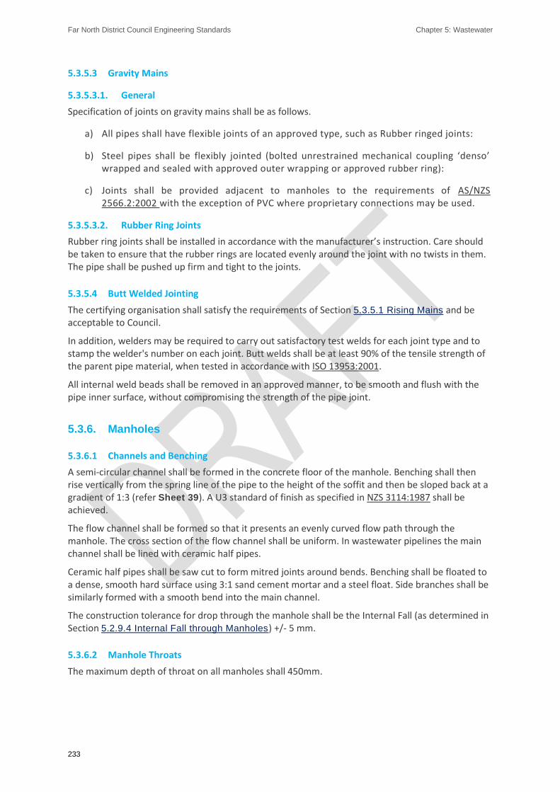
Far North District Council Engineering Standards Chapter 5: Wastewater
233
5.3.5.3 Gravity Mains
5.3.5.3.1. General
Specification of joints on gravity mains shall be as follows.
a) All pipes shall have flexible joints of an approved type, such as Rubber ringed joints:
b) Steel pipes shall be flexibly jointed (bolted unrestrained mechanical coupling ‘denso’ wrapped and sealed with approved outer wrapping or approved rubber ring):
c) Joints shall be provided adjacent to manholes to the requirements of AS/NZS 2566.2:2002 with the exception of PVC where proprietary connections may be used.
5.3.5.3.2. Rubber Ring Joints
Rubber ring joints shall be installed in accordance with the manufacturer’s instruction. Care should be taken to ensure that the rubber rings are located evenly around the joint with no twists in them. The pipe shall be pushed up firm and tight to the joints.
5.3.5.4 Butt Welded Jointing
The certifying organisation shall satisfy the requirements of Section 5.3.5.1 Rising Mains and be acceptable to Council.
In addition, welders may be required to carry out satisfactory test welds for each joint type and to stamp the welder's number on each joint. Butt welds shall be at least 90% of the tensile strength of the parent pipe material, when tested in accordance with ISO 13953:2001.
All internal weld beads shall be removed in an approved manner, to be smooth and flush with the pipe inner surface, without compromising the strength of the pipe joint.
5.3.6. Manholes
5.3.6.1 Channels and Benching
A semi-circular channel shall be formed in the concrete floor of the manhole. Benching shall then rise vertically from the spring line of the pipe to the height of the soffit and then be sloped back at a gradient of 1:3 (refer Sheet 39). A U3 standard of finish as specified in NZS 3114:1987 shall be achieved.
The flow channel shall be formed so that it presents an evenly curved flow path through the manhole. The cross section of the flow channel shall be uniform. In wastewater pipelines the main channel shall be lined with ceramic half pipes.
Ceramic half pipes shall be saw cut to form mitred joints around bends. Benching shall be floated to a dense, smooth hard surface using 3:1 sand cement mortar and a steel float. Side branches shall be similarly formed with a smooth bend into the main channel.
The construction tolerance for drop through the manhole shall be the Internal Fall (as determined in Section 5.2.9.4 Internal Fall through Manholes) +/- 5 mm.
5.3.6.2 Manhole Throats
The maximum depth of throat on all manholes shall 450mm.

Far North District Council Engineering Standards Chapter 5: Wastewater
234
5.3.6.3 Flexible Joints
All pipe lines, other than PE pipes, shall have a flexible joint adjacent to the manhole on all incoming and outgoing pipes not more than 600mm away from the manhole wall. The upper part of the pipe inside the manhole shall be cut back to the wall, the reinforcement cut out and the ends plastered with a cement mortar to a neat finish. Where the pipe is cut using a power saw the ends of the steel reinforcement shall be protected from corrosion by the application of epoxy before rust has a chance to develop. Refer to Sheet 39.
5.3.6.4 PE Pipe Connections
PE pipe shall be connected to the manholes with sliding joints, as per Sheet 33.
5.3.6.5 Sealing of Manholes
Where precast manhole units are used, the joints of abutting units shall be sealed against ingress of water with an approved sealant and with epoxy mortar on the inside and outside of the joints.
Plastic manholes shall be sealed, where required, in accordance with the FNDC Approved Materials List - Wastewater and Stormwater.
5.3.6.6 Manhole Steps
Bolt through Type Manhole Steps
The steps shall be bolted through the walls using properly formed and recessed bolt holes.
The step shall have a washer welded to it on the appropriate angle to seat flush against the inside of the manhole chamber.
Prior to tightening, BM100 shall be placed around the stainless-steel shank both inside and outside the manhole riser. After the steps have been tightened in place the outside recess which houses the nut shall be sealed with Expocrete ‘UA’ or acceptable equivalent in accordance with the manufacturer’s directions. Plastering of the recess will not be approved. The sealant shall be applied at least 48 hours before the manhole risers are required for construction.
5.3.6.7 Concrete
All concrete shall have a minimum crushing strength of 20.0 MPa at 28 days, unless otherwise specified or detailed by Council.
5.3.7. Connections
Connections will preferably be made into manholes.
Direct connection of a minor pipeline into a major pipeline shall be in accordance with the following:
a) The minor pipe diameter shall not be greater than half of the major pipe diameter:
b) Connection is made via a suitable prefabricated junction or saddle:
c) The distance between the pipeline connection and the closest inspection point shall not exceed 25m:
d) Saddling of catch-pit leads into primary lines is permitted provided that the connection is made at 45º or less to the direction of primary flow:
e) Saddling of double catch-pits is not permitted:

Far North District Council Engineering Standards Chapter 5: Wastewater
235
f) Connections shall be sealed with removable caps until required.
g) Connection locations and depths to invert shall be accurately measured and shown on As-Built Plans in accordance with the requirements of Section 1.7.2 As-Built Plans, Asset
Information Schedules, Operation and Maintenance Manuals:
h) The connection position shall be marked with a wooden stake (100 x 50mm) with ‘WW’ painted/fixed onto the stake and extending from the invert of the connection to a minimum of 600mm above ground level.
Connections shall be constructed as per Sheet 37.
5.3.8. Pump Stations
5.3.8.1 Wet Well and Valve Chamber
Care shall be exercised to ensure that the wet well chamber is vertical and set to the correct levels before the station floor is poured.
Bases in accordance with FNDC Approved Materials List - Wastewater and Stormwater shall be used.
Flotation of the chamber shall be prevented.
Pipe joints shall be sealed and made water tight.
5.3.8.2 Foundations
The wet well pump station foundation shall be constructed as specified on the approved drawings.
Where not specified on the drawings, the designer shall investigate the foundation soils and determine a suitable foundation in accordance with Section 5.2.12.6 Wet Well and Section 5.2.9.7
Manholes Requiring Specific Design). Council shall not be responsible for delays to the construction resulting from approval of designs.
5.3.8.3 Painting and Lining
Any block work mortar joints shall be pointed inside and outside and all cores filled with grout.
The outside of the block work shall be painted with a waterproofing membrane and the internal walls of the well and valve chamber shall be painted with a sealant. The products to be used shall be approved by the District Council before use.
5.3.8.4 Top Slab
The placement of reinforcement shall be carefully controlled to ensure adequate cover. The lids and frames shall be carefully set into the concrete upstands so that they fit flush with the finished upstand level. All concrete shall be ordinary grade 20 MPa crushing strength.
The lid and frame shall be as per FNDC Approved Materials List - Wastewater and Stormwater. All reinforcing steel bars shall be grade 300 deformed bars complying with AS/NZS 4671:2001. All nuts, bolts and washers shall be grade 316 stainless steel with an appropriate releasing agent applied prior to setting any nut. Where concrete shall be poured around high-density polyethylene pipe, the pipe shall be first wrapped with 1.5mm thick butynol sheeting.
5.3.8.5 Well and Chamber Lids
The primary covering lids shall be as per FNDC Approved Materials List - Wastewater and Stormwater as appropriate for the pump size selected at full development.
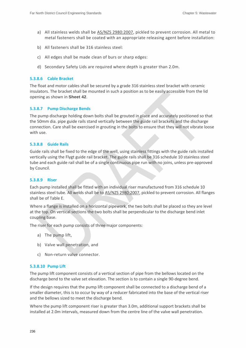
Far North District Council Engineering Standards Chapter 5: Wastewater
236
a) All stainless welds shall be AS/NZS 2980:2007, pickled to prevent corrosion. All metal to metal fasteners shall be coated with an appropriate releasing agent before installation:
b) All fasteners shall be 316 stainless steel:
c) All edges shall be made clean of burs or sharp edges:
d) Secondary Safety Lids are required where depth is greater than 2.0m.
5.3.8.6 Cable Bracket
The float and motor cables shall be secured by a grade 316 stainless steel bracket with ceramic insulators. The bracket shall be mounted in such a position as to be easily accessible from the lid opening as shown in Sheet 42.
5.3.8.7 Pump Discharge Bends
The pump discharge holding down bolts shall be grouted in place and accurately positioned so that the 50mm dia. pipe guide rails stand vertically between the guide rail brackets and the discharge connection. Care shall be exercised in grouting in the bolts to ensure that they will not vibrate loose with use.
5.3.8.8 Guide Rails
Guide rails shall be fixed to the edge of the well, using stainless fittings with the guide rails installed vertically using the Flygt guide rail bracket. The guide rails shall be 316 schedule 10 stainless steel tube and each guide rail shall be of a single continuous pipe run with no joins, unless pre-approved by Council.
5.3.8.9 Riser
Each pump installed shall be fitted with an individual riser manufactured from 316 schedule 10 stainless steel tube. All welds shall be to AS/NZS 2980:2007, pickled to prevent corrosion. All flanges shall be of Table E.
Where a flange is installed on a horizontal pipework, the two bolts shall be placed so they are level at the top. On vertical sections the two bolts shall be perpendicular to the discharge bend inlet coupling base.
The riser for each pump consists of three major components:
a) The pump lift,
b) Valve wall penetration, and
c) Non-return valve connector.
5.3.8.10 Pump Lift
The pump lift component consists of a vertical section of pipe from the bellows located on the discharge bend to the valve set elevation. The section is to contain a single 90-degree bend.
If the design requires that the pump lift component shall be connected to a discharge bend of a smaller diameter, this is to occur by way of a reducer fabricated into the base of the vertical riser and the bellows sized to meet the discharge bend.
Where the pump lift component riser is greater than 3.0m, additional support brackets shall be installed at 2.0m intervals, measured down from the centre line of the valve wall penetration.
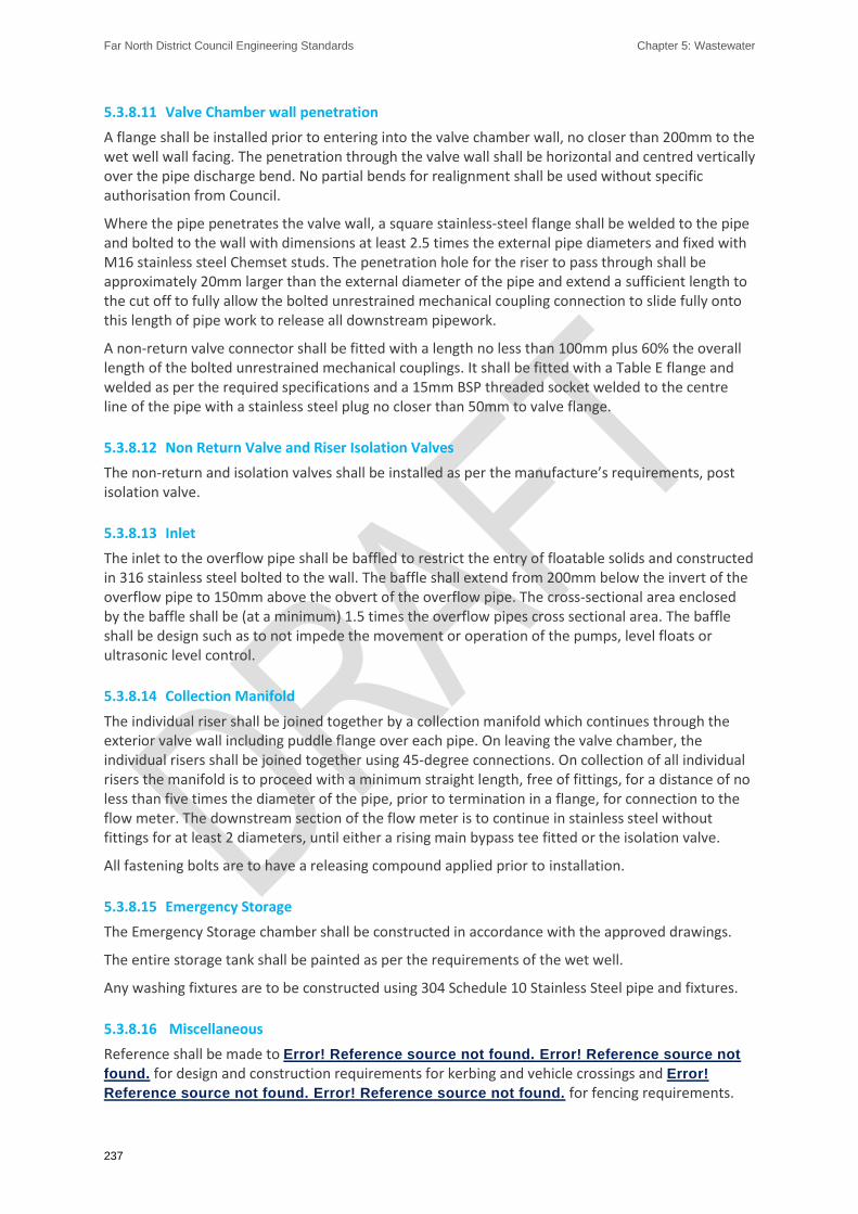
Far North District Council Engineering Standards Chapter 5: Wastewater
237
5.3.8.11 Valve Chamber wall penetration
A flange shall be installed prior to entering into the valve chamber wall, no closer than 200mm to the wet well wall facing. The penetration through the valve wall shall be horizontal and centred vertically over the pipe discharge bend. No partial bends for realignment shall be used without specific authorisation from Council.
Where the pipe penetrates the valve wall, a square stainless-steel flange shall be welded to the pipe and bolted to the wall with dimensions at least 2.5 times the external pipe diameters and fixed with M16 stainless steel Chemset studs. The penetration hole for the riser to pass through shall be approximately 20mm larger than the external diameter of the pipe and extend a sufficient length to the cut off to fully allow the bolted unrestrained mechanical coupling connection to slide fully onto this length of pipe work to release all downstream pipework.
A non-return valve connector shall be fitted with a length no less than 100mm plus 60% the overall length of the bolted unrestrained mechanical couplings. It shall be fitted with a Table E flange and welded as per the required specifications and a 15mm BSP threaded socket welded to the centre line of the pipe with a stainless steel plug no closer than 50mm to valve flange.
5.3.8.12 Non Return Valve and Riser Isolation Valves
The non-return and isolation valves shall be installed as per the manufacture’s requirements, post isolation valve.
5.3.8.13 Inlet
The inlet to the overflow pipe shall be baffled to restrict the entry of floatable solids and constructed in 316 stainless steel bolted to the wall. The baffle shall extend from 200mm below the invert of the overflow pipe to 150mm above the obvert of the overflow pipe. The cross-sectional area enclosed by the baffle shall be (at a minimum) 1.5 times the overflow pipes cross sectional area. The baffle shall be design such as to not impede the movement or operation of the pumps, level floats or ultrasonic level control.
5.3.8.14 Collection Manifold
The individual riser shall be joined together by a collection manifold which continues through the exterior valve wall including puddle flange over each pipe. On leaving the valve chamber, the individual risers shall be joined together using 45-degree connections. On collection of all individual risers the manifold is to proceed with a minimum straight length, free of fittings, for a distance of no less than five times the diameter of the pipe, prior to termination in a flange, for connection to the flow meter. The downstream section of the flow meter is to continue in stainless steel without fittings for at least 2 diameters, until either a rising main bypass tee fitted or the isolation valve.
All fastening bolts are to have a releasing compound applied prior to installation.
5.3.8.15 Emergency Storage
The Emergency Storage chamber shall be constructed in accordance with the approved drawings.
The entire storage tank shall be painted as per the requirements of the wet well.
Any washing fixtures are to be constructed using 304 Schedule 10 Stainless Steel pipe and fixtures.
5.3.8.16 Miscellaneous
Reference shall be made to Error! Reference source not found. Error! Reference source not
found. for design and construction requirements for kerbing and vehicle crossings and Error!
Reference source not found. Error! Reference source not found. for fencing requirements.

Far North District Council Engineering Standards Chapter 5: Wastewater
238
5.3.8.17 Odour Control
Odour control shall be provided as specified on the approved drawings.
Where not specified on the drawings, provision of space free of services shall be provided in case of future installation, as shown in Sheet 41.
5.3.8.18 Reinstatement
5.3.8.19 Electrical Cabinet Plinths
The electrical cabinet plinth shall be constructed as per FNDC Waste Water Pump Stations Electrical Engineering Standards
5.3.8.20 Direct Buried Cable
Where specified cables are laid directly in the ground, they shall be located not less than 0.6m below ground on a 50mm thick bed of clean sand. The trench shall be backfilled with a 75mm thick layer, measured from the top of the cable, of clean sand. Lengths of ‘Mag- Slab’ cable cover shall then be laid end to end to provide cable protection. The trench shall then be further backfilled with clean sand or soil, free from rock, stones or other debris, to a level 200mm below the surface. Orange PVC signal tape shall then be laid and backfilling completed, the surface being restored to Council’s satisfaction.
5.3.8.21 Cable Ducting
The following cable ducts are required
a) One pump cable duct and one control cable duct of 100mm dia. shall be installed from the base of the electrical control cabinet concrete plinth to the pump station chamber:
b) One 100mm duct shall be installed in the plinth for the mains cable:
c) A 50mm duct shall be installed from the electrical control cabinet concrete plinth to the flow meter:
d) A further 50mm duct shall be installed for each of the emergency storage spray wash control solenoid and/or a distal float overflow if fitted:
Each cable duct shall be fitted with a pull cord for future cable repair works and shall be sealed, to restrict corrosive fumes entering the electrical cubicle, by way of expanding foam encased in a plastic liner to allow ease of future removal.

Far North District Council Engineering Standards Chapter 5: Wastewater
239
5.4. Completion of Works
5.4.1. Testing and Inspections for Pipelines
All wastewater mains and branch pipelines, including extended connections, shall be inspected during construction. On completion of all other engineering work within the development, there shall be a final test conducted.
Where the reticulation shall be vested in Council, this final test shall be carried out in the presence of a District Council representative. If the reticulation is to remain private, this test shall be carried out in the presence of an IQP who shall certify the test and forward the results to the District Council representative
New sewer reticulation shall be completely and permanently isolated from the District Council's ‘live’ sewer reticulation until such time as all tests are passed, and written authority from Council to connect to the live sewer is obtained. Connection shall only be carried out by a Registered contractor, and the connection shall be inspected by a District Council representative before the connection is backfilled.
A minimum of 24 hours’ notice is required to be given to the District Council before any tests are carried out, so that arrangements for a representative can be made. The Developer/Contractor shall provide all fittings and materials to carry out any tests.
5.4.1.1 Inspections
The Developer/Contractor shall ensure that inspection and subsequent approval is granted before continuing with the installation. Failure to follow this process may mean that the Developer/Contractor is required to remove items or excavate work to allow inspection of standards of installation. These inspections include:
a) Set out:
b) Excavation and bedding:
c) Backfill:
d) Pre-pour Form and Reinforcing:
e) Pre-Cover Installation:
f) Water Tightness:
g) Rising Main Pressure Test:
h) Electrical Inspection.
5.4.1.2 Pipeline and Manhole Leakage Tests
The materials and workmanship used shall pass a low-pressure air test.
All tests require the pipeline to be sealed with suitably restrained plugs at both ends and at branch connections. Because porous pipes such as those of ceramic or concrete materials absorb water and can transmit air through their walls, they should have the voids filled by soaking for 24 hours prior to testing.

Far North District Council Engineering Standards Chapter 5: Wastewater
240
5.4.1.3 Low Pressure Air Test
a) Introduce air to the pipeline till a pressure of 300mm of water is reached. (This shall be measured by a manometer such as a 'U' tube, connected to the system):
b) Wait until the air temperature is uniform (indicated by the pressure remaining steady):
c) Disconnect the air supply:
d) Measure pressure drop after five minutes:
e) The pipeline/manhole is acceptable if the pressure drop does not exceed 50mm.
5.4.1.4 Manhole Leakage Tests
The materials and workmanship used shall pass a low-pressure hydraulic test.
Manholes shall be watertight and tested by plugging and filling the manhole with water (allowing sufficient time for absorption).
During the test, the level of water in the manhole shall not drop more than 5mm in 10 minutes.
5.4.1.5 Rising Main Test
Rising main pipeline and welds shall be tested in accordance with Section 6.3.3.1 Testing of Welds and Section 6.3.3.2 Pipeline Pressure Testing.
5.4.2. CCTV Inspections
5.4.2.1 General Requirements
CCTV inspection shall be carried out on every new system to vest in Council. The timing of CCTV inspection shall be determined by Council.
CCTV inspections and deliverables shall be in accordance with The New Zealand Pipe Inspection Manual, Third Edition.
All defects shall be remedied to the satisfaction of Council. Where faults are found and repaired the section of pipe shall be re-filmed to ensure that there are no further problems.
5.4.2.2 Particular Specification
Slope corrections shall be carried out where the pipe alignment is out of tolerance.
The pipe shall not be in service during the CCTV inspection. The pipe shall however be flushed with water prior to CCTV. In addition, the CCTV camera shall travel upstream with a small flow of water travelling down the pipe towards the camera. Still images of all severity ‘L’ and ‘M’ defects shall be provided.
5.4.2.3 Deliverables
The following deliverables are required.
a) Computer generated log sheets:
b) CCTV inspection record Digital Video format:
c) CCTV footage shall be referenced to ensure manhole names and DDTS ID's link footage to As-Built Plans:

Far North District Council Engineering Standards Chapter 5: Wastewater
241
d) Still images in electronic format and hard copy:
e) CCTV summary sheets in electronic format and hard copy:
5.4.2.4 Header Information Required
Refer to Quality Assurance / Quality Control Manual 2010 - Vested Assets - Inspection and Handover Procedures for CCTV header information requirements.
5.4.3. Pump Station Commissioning
Refer to Quality Assurance / Quality Control Manual 2010 - Vested Assets - Inspection and Handover Procedures for pump station commissioning requirements.

Far North District Council Engineering Standards Chapter 6: Water Supply and Reticulation
242
Chapter 6: Water Supply and Reticulation
Far North District Council Engineering Standards Chapter 6: Water Supply and Reticulation
243
6.1. INTRODUCTION ........................................................................................................................ 245
6.1.1. Water Supply System Description and Expectations .................................................. 245
6.1.2. Objectives ................................................................................................................... 245
6.1.3. Performance Standards .............................................................................................. 245
6.1.4. Reference Documents ................................................................................................ 246
6.1.5. Private Water Supply Systems .................................................................................... 247
6.1.6. Upgrading of Existing Water Supply System ............................................................... 247
6.1.7. Connection to Existing Water Supply System ............................................................. 247
6.1.8. Disconnections ............................................................................................................ 248
6.2. DESIGN ..................................................................................................................................... 248
6.2.1. Supporting Information and Calculations ................................................................... 248
6.2.2. Approval of Design ...................................................................................................... 249
6.2.3. Design Criteria and Scope ........................................................................................... 249
6.2.4. System Layout ............................................................................................................. 252
6.2.5. Fire Service Requirements .......................................................................................... 256
6.2.6. Asset Life and Approved Materials ............................................................................. 258
6.2.7. Pipe Selection.............................................................................................................. 258
6.2.8. Valves, Fittings and Marking ....................................................................................... 261
6.2.9. Hydrants ...................................................................................................................... 264
6.2.10. Surface Boxes .............................................................................................................. 265
6.2.11. Bulk Water Meters ...................................................................................................... 265
6.2.12. Service Connections .................................................................................................... 266
6.2.13. Pump Stations and Reservoirs .................................................................................... 268
6.3. CONSTRUCTION ....................................................................................................................... 268
6.3.1. Licensed and Registered Contractors ......................................................................... 268
6.3.2. Pipeline Installation .................................................................................................... 269
6.3.3. Testing and Inspections for Pipelines ......................................................................... 272
6.3.4. Disinfection ................................................................................................................. 273

Far North District Council Engineering Standards Chapter 6: Water Supply and Reticulation
244
6.3.5. Connection .................................................................................................................. 274
6.3.6. Pump Station Commissioning ..................................................................................... 275
6.4. COMPLETION OF WORKS ......................................................................................................... 275
6.4.1. Completion ................................................................................................................. 275
6.4.2. As-Built Drawings and Schedule of Asset Information ............................................... 275
6.4.3. Operation and Maintenance Manuals ........................................................................ 276

Far North District Council Engineering Standards Chapter 6: Water Supply and Reticulation
245
6.1. Introduction
6.1.1. Water Supply System Description and Expectations
This section covers the requirements for design and construction of all extensions and connections to the District Council’s water reticulation system. A connection to the District Council system shall be provided to all lots within Living and Business Environments unless the District Council confirms in writing that a connection is unwarranted, unavailable or unsuitable.
Connections in other Environments will be subject to the availability of a water supply. The District Council may however require that a water supply be provided to a development, regardless of the Environment, if the District Council considers that the connection would be a logical extension of an existing supply.
6.1.2. Objectives
The objectives of the water reticulation system are:
To supply the required quality and quantity of water to all properties as required by legislation and to meet or exceed the District Council’s performance standards.
To control the design and construction of water networks in order to ensure an acceptable water supply is available for each property, including fire flows, by providing:
i. Water main allowing an appropriate supply to each property
ii. Service connection from the main to the point of supply to each residential property
To ensure that water networks meet the minimum design life requirement, taking into account structural strength, design loadings, soil conditions and water conditions (internal and external corrosion).
To ensure that water networks are cost efficient over their design life while accounting for environmental and community impacts through integrated three waters management and water conservation.
To ensure that where properties or household units are not within a water supply area or an extension of such an area, water is collected, treated and supplied in a way that is consistent with relevant building code and other national standards,
To ensure that where properties connect to a water supply network, that network shall meet the District Council’s performance standards.
6.1.3. Performance Standards
New water supply works connected to a Water Supply Area shall be designed and constructed to achieve the following minimum standards:
Minimum pressure of 250 kPa at the point of supply for existing residential lots and for new connections at the building platform.
Minimum flow rate of 15 litres per minute at the point of supply for existing residential lots and 20 litres per minute for new connections.

Far North District Council Engineering Standards Chapter 6: Water Supply and Reticulation
246
Be designed and installed to ensure that the works will meet the Drinking Water Standards NZ and the relevant water safety plan.
Provide firefighting pressure and flow in conformance with the SNZ PAS 4509:2008.
Achieve the specified minimum asset life for systems to vest with the District Council.
All pipelines and fittings fixed by accurate positioning and the coordinates of those positions specified in terms of the District Council’s coordinate specifications in Section 1.7.2 As-Built Plans, Asset Information Schedules, Operation and
Maintenance Manuals and Appendix G Drawing Standards:
Comply with all relevant structure plan requirements and pipe sizes set by the District Council in order to provide an integrated approach to development.
The supply shall be capable of serving the entire development and any undeveloped land beyond, when that land is developed to the ultimate development intensity.
6.1.4. Reference Documents
The following documents are referenced in this Chapter;
6.1.4.1 Statutory
Health Act 1956
Regional Plan for Northland (NRC)
Resource Management Act 1991
Water Supply Bylaw 2009
District Plan and Operative District Plan
6.1.4.2 New Zealand Standards
AS 1831:2007 - Ductile cast iron
AS 3996:2006 - Access covers and grates
AS/NZS 2033:2008 - Installation of polyethylene pipe systems
AS/NZS 2280:2014 - Ductile iron pipes and fittings
AS/NZS 2638.2:2011 - Gate valves for waterworks purposes - Part 2: Resilient seated
AS/NZS 4087:2011 - Metallic flanges for waterworks purposes
AS/NZS 4129:2008 - Fittings for polyethylene (PE) pipes for pressure applications
AS/NZS 4130:2009 - Polyethylene (PE) pipes for pressure applications)
AS/NZS 4158:2003 - Thermal-bonded polymeric coatings on valves and fittings for water industry purposes
AS/NZS 4673:2001 - Cold-formed stainless-steel structures
NZS 4404:2010 - Land development and subdivision engineering
NZS 4442:1988 - Welded steel pipes and fittings for water, sewage and medium pressure gas
NZS 4522:2010 - Underground fire hydrants

Far North District Council Engineering Standards Chapter 6: Water Supply and Reticulation
247
NZS 7643:1979 - Code of practice for the installation of unplasticised PVC pipe systems
SNZ PAS 4509:2008 - New Zealand Fire Service firefighting water supplies code of practice
6.1.4.3 District Council Documents
To be confirmed
FNDC Connect-to-our-water-network Commercial and Residential Water and Wastewater Connection Application Forms
6.1.4.4 Other Referenced Documents
Drinking Water Standards for New Zealand 2005 (Revised 2018)
POP010A – Polyethylene Pressure Pipes Design for Dynamic Stresses
POP101 – PVC Pressure Pipes Design for Dynamic Stresses
UK Water Industry Specification: 4-24-01 - Specification for Mechanical Fittings and Joints for Polyethylene Pipes of Nominal Sizes 90 to 1000
6.1.5. Private Water Supply Systems
The Health (Drinking Water) Amendment Act 2007 provides that all water suppliers have a duty to ensure their water is safe to drink.
Small isolated developments outside existing water supply areas may be served by private water supply systems. These systems may serve either single or multiple lots.
Private water supply systems shall only be approved as potable water supplies if they comply with the Drinking Water Standards for New Zealand 2005 (Revised 2018), and operation and monitoring systems are implemented to ensure ongoing compliance of the system with the Drinking Water Standards for New Zealand 2005 (Revised 2018), where applicable.
The Developer is advised to consult with and shall obtain any necessary approvals from the District Council, Fire and Emergency New Zealand, Northland District Health Board and the Northland Regional Council.
6.1.6. Upgrading of Existing Water Supply System
Where the existing reticulation or a proposed extension cannot comply with the minimum flow or operating pressure requirements, the Developer may be required to provide and install elevated storage and/or booster pumping systems to the approval of the District Council.
6.1.7. Connection to Existing Water Supply System
6.1.7.1 Work on Existing Water Mains
Where work is required on or over existing water mains, the Developer may be required to lower, move or protect the main to ensure cover and separation distances are met.
Only a Licensed Contractor will be permitted to work on existing live water mains (see 6.3.1
Licensed and Registered Contractors).
The Developer shall pay the full cost of this work.

Far North District Council Engineering Standards Chapter 6: Water Supply and Reticulation
248
6.1.8. Disconnections
Where an existing water supply connection to a development is no longer required or is not adequate the existing connection shall be permanently disconnected.
District Council approval is required for disconnections from the water supply network to ensure continued network integrity and quality of supply.
Disconnections shall only be undertaken by a District Council Licensed Contractor.
FNDC Connect-to-our-water-network (obtained from the District Council’s website or from District Council offices) shall be submitted to the District Council and approved before any work may be undertaken.
A District Council representative shall inspect all disconnections before backfilling takes place. All District Council owned fittings including meter and backflow preventer shall be returned to the District Council.
6.2. Design
6.2.1. Supporting Information and Calculations
In addition to the general requirements in Section 1.5 Design for design submissions, the water supply design submission shall:
Include analysis of the water demand for consumption and firefighting. Firefighting flows for industrial land shall be obtained from SNZ PAS 4509:2008, based on type and size of industry,
Include analysis of potential water hammer, surge and fatigue effects and demonstrate appropriate mitigation measures are incorporated into the design,
Demonstrate that the existing and proposed water supply reticulation is adequate and identify existing and proposed connection points to serve the proposed development,
Where the proposal would use more than 10% of the capacity of the existing water source and/or treatment facilities, demonstrate that the existing water source and/or treatment facilities are adequate to serve the proposed development,
Demonstrate that required firefighting pressures and flows can be met from all hydrants and service connections,
Submit details of any system components that do not meet the performance standards (Section 6.1.3 Performance Standards), i.e. components with asset lives less than 100 years, and
Contain Producer Statements forms (refer Appendix C ES – PS1) or alternative approved, identifying the design standards used, and certifying that the design complies with the ES.
All analysis shall include appropriate supporting information, calculations, reports, etc. to enable an external review to be undertaken without reference back to the design originator.
For industrial uses, the type and size of industry used to establish water use and the Water Supply Classification for firefighting supply shall be identified. This information will be put on the relevant property files by the District Council.

Far North District Council Engineering Standards Chapter 6: Water Supply and Reticulation
249
Note: Refer to Appendix A Design for Surge and Fatigue for details of designing for surge and fatigue.
6.2.2. Approval of Design
The drawings and calculations will be reviewed by the District Council.
Following any necessary amendments, the Developer shall submit a final set of design drawings for construction, which shall include all necessary endorsements by IQP’s and shall be clearly marked as a construction revision. These final drawings will be stamped and signed by the District Council.
Only drawings stamped and signed by the District Council are approved drawings.
Unless specifically stated otherwise, the approval of drawings does not supersede the requirements or obligations of the ES.
6.2.3. Design Criteria and Scope
6.2.3.1 General Requirements
Proposed water supply works shall be designed for connection to a District Council approved location on the existing water supply network.
The District Council may specify the diameters and classes of pipes to be used for all reticulation within the development, and specify reticulation alignment.
Designers shall consider the hydraulic adequacy of the network including the specified levels of service, water quality and impact on the existing network.
For design purposes, and subject to availability, the District Council may:
provide details of the working pressure of the existing water supply network, or of pressures at the approved connection point to the existing reticulation, and
provide details of the capacity of existing water supply facilities.
Where this information is not available from District Council records, or further information is required for the design, the Developer shall consult with the District Council regarding the completion of any investigations.
The Developer shall cover the cost of investigations required to complete their design to the ES.
The District Council’s water pressure management programme seeks to reduce pressures over time to 400 KPa (where practicable). Unless otherwise agreed with the District Council all designs shall be to 400 KPa or the working pressure, whichever is the lesser.
Where pressures are likely to exceed these levels, the District Council may require that a pressure-reducing device be installed to ensure acceptable working pressures.
The hydraulic design of reticulation, outside the scope of simplified methods in the ES, shall be carried out by an IQP (Refer to Section 1.5 Design) experienced in the design of water reticulation systems.
6.2.3.2 Scope of Design
The scope of design shall include:
Pipe sizes, material, and layout of the reticulation,
Hydraulic design,

Far North District Council Engineering Standards Chapter 6: Water Supply and Reticulation
250
Service connection locations, including multi-connection box locations,
Types and locations of valves, hydrants and other similar control devices
Thrust blocks and anchors (where applicable),
Pipe cover and protection appropriate to expected loading,
Bedding and backfill, and any specific installation requirements (e.g. pipe anchors/bulkheads), and
Preparation of construction specifications.

Far North District Council Engineering Standards Chapter 6: Water Supply and Reticulation
251
Design drawings shall comply with the requirements of Section 1.5.3.3.5 Design Statements and
Engineering Plans and Appendix G Drawing Standards and the following requirements:
Infill developments (not exceeding four lots): may be shown on combined services design drawings, and
All other developments: water reticulation shall be on separate drawings from other services.
6.2.3.3 Domestic Demand
The design shall provide for annual, seasonal and peak domestic demand, and allow for a minimum domestic demand of 300 litres/person/day.
6.2.3.4 Commercial and Industrial Demand
The water demands for commercial and industrial areas, and for irrigation shall be analysed and specifically allowed for in the design.
6.2.3.5 Peak Flows
Peak Flows (PF) shall be calculated as follows:
Peak Day Demand (over a 12-month period) = Average Day Demand x PF, where;
For populations below 2,000 PF = 2,
For populations above 2,000 the District Council shall specify PF.
Peak Hourly Demand = Average Hourly Demand (on peak day) x PF (over a 24-hour period) and where:
For populations below 2,000 PF = 5,
For populations above 2,000, the District Council shall specify PF.
The minimum flow for an individual 20mm ID residential connection shall be 20 litres per minute at the meter location.
6.2.3.6 Pressure Fluctuations
The design shall ensure that large pressure fluctuations due to variations in usage are avoided.
Unless otherwise approved by the District Council, head losses in existing and new mains at peak flow shall be limited to:
DN less than or equal to 150mm: 5m per 1000m of pipeline
DN greater than or equal to 200mm: 3m per 1000m of pipeline.
6.2.3.7 Flow Velocities
Pipelines shall be designed for flow velocities within the range of 0.5 – 2.0m/s.
6.2.3.8 Operating Pressures
The minimum service water pressure, in other than firefighting conditions, shall be 250kPa at ground level the building envelope of each lot.
Far North District Council Engineering Standards Chapter 6: Water Supply and Reticulation
252
Where minimum service water pressure cannot be met at the house site, a booster pumping system may be required. Provided that the water supply reticulation satisfies firefighting performance standards, private pumps serving up to five lots may be provided. The lot owners shall be jointly responsible for ongoing maintenance of the booster system and this responsibility shall be registered on the affected property titles.
The preferred operating pressure in the reticulation system is 400kPa. The District Council may require that a pressure reducing valve be installed to reduce the pressure in any development to 400kPa or below.
For the purpose of pipeline design, the maximum static water pressure at ground level for any lot shall be 600kPa, unless otherwise approved by the District Council. In cases where the static pressure exceeds 600kPa, a pressure reducing valve may be required.
6.2.3.9 Capacity and Future Expansion
Designers shall allow for the effect on existing and potential future development in an area when determining whether there is capacity to serve a subdivision.
The District Council has the discretion to make a final decision on water availability.
Where future development beyond the current development boundaries is practicable, reticulation (sufficient to serve the future development) shall be extended to the boundaries of the current development. Costs of the extensions shall be at the Developer’s expense.
Where applicable, the Developer shall provide a blanked off line to serve future development. The District Council may require installation of additional pipelines or fittings in order to prevent stagnant areas occurring in the extended reticulation prior to any future development proceeding.
6.2.4. System Layout
6.2.4.1 Mains and Rider Mains
Mains and rider mains shall in general be located within public road reserves.
A principal main shall be laid on at least one side of all carriageways. The District Council may also require principal mains on both sides of arterial and dual carriageway roads, and also in industrial subdivisions.
A rider main shall be laid along the road frontage of all lots not fronted by a principal main including the circular head of cul-de-sacs. Rider mains shall be designed as ring mains, with a connection to a principal main at both ends as shown in Sheet 45. Fire mains may be required in a private way or private road to meet proximity requirements for buildings. See Section 6.2.9.2 Hydrant Locations for hydrant locations.
6.2.4.2 Reticulation on Private Property
Location of District Council owned reticulation within private property, or down right-of-way or private roads, requires specific approval from the District Council.
Approval of public reticulation located in private property or right-of-way will depend upon:
the number and length of connections required, and/or
the requirement to provide fire cover that complies with SNZ PAS 4509:2008.
If approved, the following shall be provided:

Far North District Council Engineering Standards Chapter 6: Water Supply and Reticulation
253
An easement in favour of the District Council over the private property, right-of-way or private access,
The main shall be laid in a duct,
The required minimum clearances from other services (6.2.4.3 Separation from
Other Services) shall apply, and
Valves and surface boxes shall be located in berms, clear of carriageways where practicable.
The District Council may require the legal width of the access to be greater than the minimum specified in Section 3.2.28 Private Accessways in order to ensure minimum clearances from other services.
Details on points of supply are as stated in the FNDC Water Supply Bylaw 2009.
6.2.4.3 Separation from Other Services
Water mains shall be laid at a higher level than wastewater pipelines to avoid cross contamination.
Water mains shall have a minimum clearance, between the outside edges of the water service and any other service, of:
500mm, or
three times the water service diameter,
whichever is the greater, or
the greater of the required clearances between the relevant services as follows in the table below and as shown on Sheet 29 and Sheet 30
unless otherwise approved by the District Council.
Table 6-1: Minimum Clearance from Other Utilities
Utility Clearance to other Utilities Other than Watermains (mm)
Clearance to Watermains (mm)
Stormwater 300 H, 150 V
Wastewater 300 H, 150 V 1000 H, 500 V or 600 H, 750 V
Electricity 500 H, 225 V 500 H, 225 V when watermains < or = 200mm ID
1000 H, 225 V when watermains > 200mm ID
Telecom and Gas
300 H, 150 V 300 H, 150 V when watermains < or = 200mm ID
600 H, 150 V when watermains > 200mm ID
Watermains As above 600 H, 500 V when new > 375mm ID
300 H, 150 V when new < 200mm ID and existing is < 375mm ID
600H, 150 V when new > 200mm ID and existing is < 375mm ID

Far North District Council Engineering Standards Chapter 6: Water Supply and Reticulation
254
Vertical clearance applies when wastewater mains cross another utility service, except in the case of water mains when a vertical clearance shall always be maintained, even when the water and wastewater pipes are parallel. The water main shall always be located above the wastewater pipe to minimize the possibility of backflow contamination in the event of a main break.
Clearance can be reduced further to 150mm for distances of up to 2m when passing installations such as poles, pits and small structures, providing the structure is not destabilized in the process.
When a wastewater pipe is at the minimum vertical clearance below the water main (500mm), maintain a minimum horizontal clearance of 1000mm. This minimum horizontal clearance can be progressively reduced to 600mm as the vertical clearance is increased to 750mm.
Where a wastewater main crosses other services, it shall cross at an angle as near as practicable to 90 degrees.
Clearance shall be measured from the outside of each pipe or duct.
6.2.4.4 Separation from Structures
Pipes adjacent to existing buildings and structures shall be located clear of the ‘zone of influence’ of the building foundations. If this is not practicable, a Specific Design shall be undertaken to cover the following:
Protection of the pipeline,
Long term maintenance access for the pipeline, and
Protection of the existing building or structure.
Sufficient clearance for laying and access for maintenance is also required. Table 6-2 may be used as a guide for minimum clearances for mains laid in public streets.
Table 6-2: Clearances from Structures
Pipe Diameter (DN) Minimum Clearance to wall or building (mm)
<100 600
100 to 150 1000
200 to 300 1500
375 2000
Note: These clearances shall be increased for mains in private property (even with easements) as access is often more difficult and the risk of damage is greater
6.2.4.5 Water Mains near Trees and Existing Reticulation
Where any pipe or cable is laid alongside existing water reticulation then a separation of at least 1m is to be maintained where practicable so as not to disturb the existing trench.

Far North District Council Engineering Standards Chapter 6: Water Supply and Reticulation
255
6.2.4.6 Pipe Cover
All reticulation located in areas not subject to traffic loading shall have a minimum of 600mm of cover between the top of the pipe and finished ground level.
Under carriageways or other areas subject to traffic loading, minimum cover over reticulation shall be 900mm.
The District Council may require greater depth of cover in certain circumstances.
Where the minimum (or District Council specified) cover requirements cannot be provided, then pipe protection shall be provided in accordance with Sheet 32. All pipes with less than 500mm cover under carriageways shall be laid in a larger protective duct.
Where excavations for entrances to developments encounter existing water supply reticulation, then those pipelines shall be relocated to comply with the cover requirements of this section. The Developer shall cover the cost of relocation of the existing reticulation to provide compliant cover.
The sections of pipe adjacent to a carriageway crossing shall be gradually deepened either side of the carriageway, to allow the required cover to be achieved under the carriageway without provision of vertical bends. Air valves may be required on the resulting crests in the pipe.
Service connections shall not have less than 600mm cover under footpaths and berms terminating at a meter manifold as per Sheet 46. Reduced cover is accepted where the service line connects to the main and as the service line approaches point of supply.
6.2.4.7 Thrust and Anchor Blocks
On all mains exceeding 50mm diameter where no end restraint is available, concrete anchor blocks shall be provided at all valves, bends, tees, reducers and dead ends.
Generally, anchor/thrust blocks are not required on PE mains, except where a connection is made to an unrestrained pipe or fitting.
The size of anchor block bearing surfaces shall be specifically designed. Sheet 50 gives guidelines for shape and size for a soil with a bearing pressure of 100kPa and a design pressure of 1500kPa. These shall be confirmed by an IQP at the time of design.
Anchor block concrete shall be ordinary grade concrete supplied from a graded plant and have a minimum compressive strength of 17.5Mpa at 28 days, unless otherwise approved by the District Council. All anchor blocks shall be poured using adequate formwork, with the bearing surface poured against an undisturbed soil surface. A protective wrapping shall be provided between the pipe and concrete.
Reference should be made to drawings WS-003, 004 & 005 in NZS 4404:2010 for typical thrust block locations when used with pipes without end restraint.
If reticulation is being extended from the end of an existing pipe with a blank cap and thrust block, the thrust block shall be removed and the new pipe continued in the same alignment as the original pipe.
6.2.4.8 Pipe Bridges and Bridge Crossings
Pipe bridges and pipelines attached to bridges shall be specifically designed by an IQP for the particular environment.
The underside of the pipe bridge structure shall be a minimum of 300mm above the Q100 (+20%) flows.
Where pipelines are fixed to road bridges, they shall be installed on the downstream face of the bridge and shall be located above the 1 in 100-year return period flood level.

Far North District Council Engineering Standards Chapter 6: Water Supply and Reticulation
256
Piles shall be concrete unless specifically approved by the District Council.
Pipes shall be ductile iron or coated steel and shall be provided with an appropriate Petrolatum wrapping as per clause 3.6 of the FNDC General Specification for Installation of Watermains.
The Developer shall be responsible for obtaining all necessary building and/or resource consents.
6.2.5. Fire Service Requirements
6.2.5.1 Fire Risk Classification
A “normal single family home” will have a classification FW2. Other buildings with a sprinkler system fitted to an approved standard may have a classification of FW2.
All other buildings are classified according to Table 1, SNZ PAS 4509:2008.
6.2.5.2 Fire Fighting Water Requirements
The minimum standard of water supply for firefighting shall be as set out in Table 6-3.
The required flow shall be obtained from the maximum number of fire hydrants as scheduled within an accessible distance of 270m of any fire risk. The accessible distance is via a route from the fire hydrant to the property, following roads, driveways or rights of way.
For maximum hydrant spacing refer to Section 6.2.9.2 Hydrant Locations.
The water supply requirements for fire protection systems shall be considered in addition to firefighting water supplies. All firefighting water requirements are additional to the expected daily demand.
The minimum firefighting residual running water pressure shall be 100kPa at any fire hydrant. For industrial subdivisions, the water supply classification to which the system has been designed shall be stated. Following approval, this classification shall be registered against all property titles as a consent notice, noting that the design does not necessarily account for future consumption from other large users.
For large industrial sites, the requirements of SNZ PAS 4509:2008 may not be able to be met from existing Water Services infrastructure. In such cases, the Developer may shall provide a supplementary supply. The Developer shall establish requirements and obtain approval for such a supply from the Fire Service, and provide evidence of this approval with the consent application.
Where any development is of such a nature that the required flows cannot be achieved without serious negative effects on the system, the Developer shall install sprinklers or provide an alternative means of firefighting to the satisfaction of the NZ Fire Service.
For non-reticulated firefighting water requirements refer to SNZ PAS 4509:2008.
Table 6-3: Simplified Method for Determining Fire Fighting Supplies
Water Supply Classification
Water flow within an accessible distance of 135m (l/s)
Additional water flow required within an accessible distance of 270m (l/s)
Water storage time (min)
Water storage volume (m3)
Maximum number of fire hydrants to provide flow
FW1 7.5 15 7 1
FW2 12.5 12.5 30 45 2

Far North District Council Engineering Standards Chapter 6: Water Supply and Reticulation
257
Water Supply Classification
Water flow within an accessible distance of 135m (l/s)
Additional water flow required within an accessible distance of 270m (l/s)
Water storage time (min)
Water storage volume (m3)
Maximum number of fire hydrants to provide flow
FW3 25 25 60 180 3
FW4 50 50 90 540 4
FW5 75 75 120 1080 6
FW6 100 100 180 2160 8
FW7 As calculated (see note 7 below)
Refer to Table 1 SNZ PAS 4509:2008 for Water Supply Classification.
Notes – (from SNZ PAS 4590:2008)
(1) Table 1 lists the minimum requirements for firefighting water supplies. In developing towns’ main reticulation systems, a water supply authority needs to cater for domestic/industrial water usage in addition to the above. This procedure is outlined in Appendix K. of the Standard
(2) Special or isolated fire hazards which have higher requirements in an area of lower water supply classification shall determine measures to mitigate the hazard or increase the water supply (see 4.4).
(3) Where houses have a sprinkler system installed to an approved Standard, the distance to a fire hydrant or alternative water supply may be negotiated by agreement with the Fire Region Manager.
(4) The water requirements for fire protection systems shall be considered in addition to the firefighting water supplies, as detailed in table 1 (FW2), the fire protection system demand plus 1500 L/min (25 L/s) at 1 bar residual pressure.
(5) The minimum flow from a single hydrant shall exceed 750 L/min (12.5 L/s), except for those cases where a home sprinkler is installed, in which case the minimum is 450 L/min (7.5 L/s) while the maximum design flow, for safety reasons, is limited to 2100 L/min (35 L/s).
(6) If the minimum water storage requirement as listed in the above table is not available from the reticulated system (reservoir), water can be sourced from an ‘alternative supply’ as approved by the Fire Region Manager. This water supply shall always be within 90 m of the fire risk.
(7) FW7 is for either special or isolated hazards or where the fire hazard due to the size of the largest firecell and its fire hazard category make specific fire engineering assessment necessary. Appendix H and J [of SNZ PAS 4590:2008] shall be used as the basis for calculating this required firefighting water supply.
(8) See Appendix B [of SNZ PAS 4590:2008].
6.2.5.3 Dedicated Sprinkler and Fire Fighting Water Mains
Dedicated sprinkler and firefighting water mains require specific approval from the District Council.
Design of sprinkler systems shall demonstrate that the minimum operating pressure of 250kPa is available.
All dedicated water mains for sprinkler systems shall have a District Council approved testable double check (or RPZ) detector backflow prevention device together with isolation valves for testing, located within, but as close as practicable to the property boundary. The owner shall be responsible for the ongoing maintenance of the sprinkler system.
All dedicated private firefighting water mains with hydrants connected to them shall have an RPZ backflow prevention device together with isolation valves for testing located within, but as close as practicable to the property boundary together with an electromagnetic water meter, or NZ Insurance District Council approved meter. The backflow prevention device shall be mounted above

Far North District Council Engineering Standards Chapter 6: Water Supply and Reticulation
258
ground level and be protected by a cage to avoid damage. The hydrants shall not be used for any purpose other than firefighting.
6.2.5.4 Domestic Sprinkler Systems
Domestic sprinkler systems shall be designed to run at a pressure of no more than 250kPa, which is the target minimum operating pressure at customer meters.
If the sprinkler system is a dead-end system and not linked to the internal plumbing, then a backflow preventer shall be installed.
All sprinkler systems shall be metered.
6.2.6. Asset Life and Approved Materials
6.2.6.1 Design Life
Water supply networks shall be designed and constructed for an asset life of at least 100 years.
However, some components such as pumps, metering, control valves, and control equipment will require earlier renovation or replacement. Details of expected lives of these assets shall be provided accordance with Section 6.2.1 Supporting Information and Calculations.
6.2.6.2 Approved Materials
The FNDC Approved Materials List - Water Services referenced in the ES, includes a process for adding or removing materials and fittings from the list. The use of alternative materials from those in the list is subject to specific approval by the District Council.
Materials and pressure ratings for pipelines greater than DN150 shall be determined by Specific Design and in consultation with the District Council.
6.2.7. Pipe Selection
6.2.7.1 General Requirements
The size, class and material of water supply mains shall be selected to achieve the objectives and meet the performance standards set out in Section 6.1.2 Objectives and Section 6.1.3 Performance
Standards.
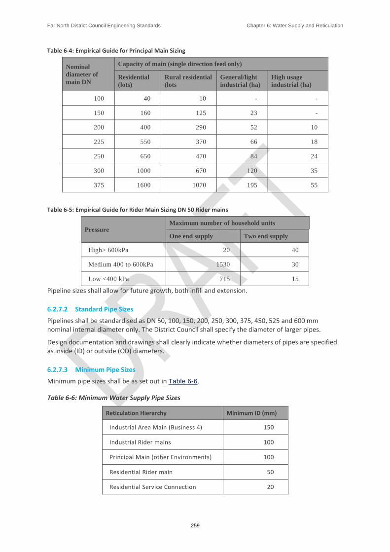
Far North District Council Engineering Standards Chapter 6: Water Supply and Reticulation
259
Table 6-4: Empirical Guide for Principal Main Sizing
Nominal
diameter of
main DN
Capacity of main (single direction feed only)
Residential
(lots)
Rural residential
(lots
General/light
industrial (ha)
High usage
industrial (ha)
100 40 10 - -
150 160 125 23 -
200 400 290 52 10
225 550 370 66 18
250 650 470 84 24
300 1000 670 120 35
375 1600 1070 195 55
Table 6-5: Empirical Guide for Rider Main Sizing DN 50 Rider mains
Pressure Maximum number of household units
One end supply Two end supply
High> 600kPa 20 40
Medium 400 to 600kPa 1530 30
Low <400 kPa 715 15
Pipeline sizes shall allow for future growth, both infill and extension.
6.2.7.2 Standard Pipe Sizes
Pipelines shall be standardised as DN 50, 100, 150, 200, 250, 300, 375, 450, 525 and 600 mm nominal internal diameter only. The District Council shall specify the diameter of larger pipes.
Design documentation and drawings shall clearly indicate whether diameters of pipes are specified as inside (ID) or outside (OD) diameters.
6.2.7.3 Minimum Pipe Sizes
Minimum pipe sizes shall be as set out in Table 6-6.
Table 6-6: Minimum Water Supply Pipe Sizes
Reticulation Hierarchy Minimum ID (mm)
Industrial Area Main (Business 4) 150
Industrial Rider mains 100
Principal Main (other Environments) 100
Residential Rider main 50
Residential Service Connection 20

Far North District Council Engineering Standards Chapter 6: Water Supply and Reticulation
260
6.2.7.4 Pipe Class
Standard approved pipe classes are given in Table 6-7. Other classes shall not be used, except with District Council approval.
Table 6-7: Pipe Classes
Class of Pipe and Fittings
Maximum Working Pressure
Head (m) kPa
Class 12 (PN12.5) 120 1200
Class 16 (PN16) 160 1600
6.2.7.5 Pipe Materials
The following pipe materials are approved for use:
PE80/PE100 to AS/NZS 4130:2009,
Ductile Iron to AS/NZS 2280:2014, and
Steel to NZS 4442:1988.
Water mains shall be constructed using PE80 or PE100 unless otherwise approved or required by the District Council.
PE pipes shall conform to the following requirements:
Rider mains and service connections of 50mm ID and under shall use solid blue PE 80 pipe or black internally with a blue outer skin,
PE 80 and PE 100 water mains with a nominal ID of 100mm or greater shall be black internally with a blue outer skin, and
The blue outer skin shall be co-extruded with the internal material and have a thickness equivalent to 10% of the pipe wall thickness unless otherwise approved by the District Council. The Developer shall provide evidence of the blue outer skin thickness.
Note: Blue, or black with blue stripe pipes or ducts shall not be used for any application other than potable water supply within the Far North District Water Supplies.
Note: PVC is not an acceptable pipe material for new installations, it shall only be used for repair work carried out by the District Council.
Note: Steel or ductile iron will only be approved where the use of PE is not appropriate, e.g. in above ground applications.
Note: Use of steel or ductile iron is subject to specific District Council approval, which will require evidence of tight quality control of fabrication and construction.
Note: Steel and ductile iron pipes shall have a spun concrete lining not less than 6mm thick, and an external coating of extruded blue HDPE as detailed in the FNDC Approved Materials List - Water Supply. Care shall be taken not to damage the coating during handling and installation. No welding is permitted after the protective coatings have been installed on the pipes.

Far North District Council Engineering Standards Chapter 6: Water Supply and Reticulation
261
6.2.8. Valves, Fittings and Marking
6.2.8.1 General
All valves and fittings shall be in accordance with FNDC Approved Materials List - Water Supply, the main points of which are summarised below.
Pipe fittings above ground, or in non-aggressive ground conditions, shall be ductile iron to AS 1831:2007, powder coated with Rilsan 11 or approved equivalent to AS/NZS 4158:2003. Where applicable they shall comply with AS/NZS 2280:2014.
Flanges shall be to AS/NZS 4087:2011 PN16. Fittings laid adjacent to other fittings shall have flanged joints. Where fittings are located in on-line positions, flexible (bolted unrestrained mechanical coupling) joints may be permitted subject to approval of the District Council (bolted unrestrained mechanical coupling joints may not be used on PE pipe).
All bolts and nuts shall have washers and be 316 stainless, plus protective wrapping. This shall be an approved Petrolatum system primer paste covered with ‘Petrolatum mastic (for moulding around irregular profiles such as flanges, valves etc. to provide a suitable profile for wrapping), followed by Petrolatum tape or ‘Greensleeve’ over wrap, or approved alternatives complying with the same standards.
6.2.8.2 Sluice Valves and Peet Valves
6.2.8.2.1. Types
Sluice valves used on principal mains shall be ductile iron Resilient Seated valves to AS/NZS 2638.2:2011 and fully nylon coated to AS/NZS 4158:2003. They shall be bi-directional, anti-clockwise closing, have raised flange faces to AS/NZS 4087:2011 and shall be provided with cast iron spindle caps.
The depth to the top of the spindle from the finished ground surface shall be, where practicable, between 75mm and 250mm and the spindle shall be truly vertical. Where depth to the spindle exceeds 500mm a spindle extension shall be used to bring the top of the spindle between 75mm and 250mm of the surface.
Peet Valves used on rider mains shall be ductile iron Resilient Seated valves to AS/NZS 2638.2:2011 and fully nylon coated to AS/NZS 4158:2003. They shall be clockwise closing with a ductile iron handwheel. They shall have threaded end connections to which a 63mm PE compression coupling can be screwed.
Use of butterfly valves requires the specific approval of the District Council. They shall be anti-clockwise closing and shall be fitted with travels tops and a special type of spindle or cap dolly, which differs from those for sluice valves.
6.2.8.2.2. Location of Valves and Fittings
Valves shall be so arranged that a shutdown of any section of water main will affect as small an area as practicable, in accordance with Table 68 Valve Spacing.
Valves located at intersections shall be fixed on all legs of a tee or cross installation and shall, where practicable, be located in berm areas free of the carriageway.
A peet valve is required on rider mains at the connection to the principal main. Where there are more than 15 connections on the rider main, an isolating peet valve shall be provided in the middle of the rider main.
Valve layout on the principal and rider mains shall enable the rider main to be flushed through the nearest hydrant. Where this is not practicable a scour valve may be required.

Far North District Council Engineering Standards Chapter 6: Water Supply and Reticulation
262
Where the rider main is a continuation from the end of the principal main in the same direction, the end of the principal main shall be provided with a peet valve immediately after the reducer.
The maximum spacing of valves shall be in accordance with Table 68 Valve Spacing

Far North District Council Engineering Standards Chapter 6: Water Supply and Reticulation
263
Table 6-8: Valve Spacing
Water Main Size DN
No of Property Service Connections (nominal)
Maximum Spacing of Valves (m)
≤ 150 40 300*
200 - 300 100 750
≥ 375 150 1000
* In rural areas, the maximum spacing may be increased to 500m
6.2.8.3 Air Release and Scour Valves
Air Release and Scour Valves shall be located within the network, as required, to provide effective release of entrained air and effective flushing of the system. The District Council may specify the type, number and/or location of air release and scour valves.
Air release valves shall be ductile iron and be a combination type as per the FNDC Approved Materials List - Water Supply They shall be installed in a fully draining box as per Sheet 51.
A connection to a suitable drainage system shall be provided for all scour points where practicable.
6.2.8.4 Pressure Reducing Valves
Pressure reducing valves may be required by the District Council where water pressure is greater than 600kPa and a significant number of properties are affected or potentially affected (typically over a distance of 500m, and affecting more than 40 lots).
Pressure reducing valves shall be installed as per Sheet 52. Pressure gauges are required upstream and downstream of the valve. Only valves as specified by the FNDC Approved Materials List - Water Supply shall be used.
The valve shall be installed in an approved chamber with isolating valves to allow removal.
6.2.8.5 Valve Marking
The position of all valves on water mains shall be indicated by a District Council approved reinforced concrete indicator post bearing the inscribed letters ‘SV’, ‘AV’, ‘BV’ or ‘PV’ in black to indicate either sluice valves, air valves, butterfly valves or peet valves, respectively.
A concrete mowing strip 150mm wide shall surround the post when it is set in the grassed berm.
The correct main size in millimetres and the distance between marker and valve in metres shall be attached to the post using black adhesive lettering near the top of the post.
There shall also be a rectangle painted on the kerb in a direct line between the valve and the marker post. This rectangle shall be white unless the valve shall be normally closed in which case it shall be red. In all cases the colour of the valve box lid shall match the rectangle.

Far North District Council Engineering Standards Chapter 6: Water Supply and Reticulation
264
6.2.9. Hydrants
6.2.9.1 Hydrant General Requirements
All mains of 100mm diameter or greater shall be provided with hydrants. Hydrants shall comply with the following requirements:
Hydrants shall be ductile iron, clockwise closing, screw down type in accordance with NZS 4522:2010 and shall be tall pattern.
Hydrants and risers shall be fully coated inside and out with blue nylon to AS/NZS 4158:2003.
Hydrant stoppers shall be resilient seated and encapsulated in nitrile or EPDM rubber.
Hydrant spindles shall be non-rising stainless steel or DR brass, stem seals shall be nitrile rubber ’O’ rings (gland packing is not acceptable).
Hydrant tees shall be ductile iron and coated in Rilsan 11 or approved alternative complying with AS/NZS 4158:2003.
Sealing cup washer shall be of nitrite rubber and the gland seal shall be either braided PTFE yarn or a minimum of two captive ‘O’ sealing rings.
Hydrants shall not be self-draining.
6.2.9.2 Hydrant Locations
Hydrants shall be located opposite the common boundaries of lots and spaced at intervals not exceeding 135m on principal mains.
For developments requiring pipelines greater than or equal to 100mm ID on both sides of the road, hydrants shall be fitted on the larger pipe as above, and on the smaller pipe at intervals not exceeding 270m.
Terminal hydrants shall be within 135m of the furthermost portion of any building site along a route that is fully accessible2. In cul-de-sacs or other terminal streets the last hydrant shall be as per Sheet
45 and not be more than 65m from the end of the street.
Where a private way is more than 65m long, a hydrant shall be provided at the street end of the private way or on the other side of the street immediately opposite the entrance.
Council may require a 100mm diameter principal main with hydrant to be constructed within a private way or private road to ensure fire coverage. In this instance, adequate turning must be provided within 50m of the end of the private way. Adequate turning shall mean a turning area of no less than 11.3m radius, or as per Fire and Emergency NZ requirements. The access shall be designed to take heavy vehicles.
Where an isolated risk is identified such as a school or large industrial complex, a private fire main may shall be constructed onto that lot. No other reticulation shall be taken off this line. Meter and backflow requirements shall apply as per the ES.
2 The definition of accessible is a route from the fire hydrant to the building or building site following roads, driveways or right of ways.

Far North District Council Engineering Standards Chapter 6: Water Supply and Reticulation
265
Hydrants shall be readily accessible for fire appliances and should be positioned near street and private way intersections and at least 6m from any building.
Hydrant risers shall be used where necessary to ensure that the top of the spindle is not less than 75mm nor greater than 250mm below finished surface level.
Hydrants are also required at all dead-end lines, high points for the purpose of air release, and low points to enable mains flushing if a normal washout cannot be fitted.
6.2.9.3 Hydrant Marking
Location marking of fire hydrants shall be to SNZ PAS 4509:2008 - APP L.
Markings in carriageways and footpaths shall use yellow triangular Thermoplastic Hydrant Markers on AC road surfaces, painted Thermoplastic Hydrant Markers on chip seal surfaces, and blue ‘Cats-Eye’ markers located on the hydrant side of the road centre line. Final triangular hydrant marking should not be until the near the end of the Defects Liability Period. Marking around hydrant boxes in parking bays shall be yellow retroflective paint.
Yellow painted, District Council approved reinforced concrete marker posts shall be fixed 225mm from the street boundary at the closest point to and facing the hydrant, with the top of the post 600mm above finished ground level.
A concrete mowing strip 150mm wide shall surround the hydrant marker post when it is set in the grassed berm.
The correct main size in millimetres and the distance between marker and hydrant in metres shall be attached to the post using black adhesive lettering near the top of the post.
6.2.10. Surface Boxes
All valves and hydrants shall be accessible via surface boxes as shown on Sheet 45 and Sheet 49.
Surface boxes shall be heavy duty cast iron or ductile iron, and be directly above the valve or hydrant. Hydrant boxes in “Arterial” roads and State Highways shall be Motorway Grade. All other hydrant boxes in road carriageways shall be manufactured to AS 3996:2006. All hydrant boxes to be installed to NZS 4522:2010.
The long side of the surface box shall run parallel to the water main. The box shall be supported on concrete risers sized to provide unobstructed access to the valve or hydrant. For hydrants, this shall include easy access for standpipes and installation of data logging equipment.
The design shall ensure that surface loading (traffic, etc.) is not transmitted via the box and supports to the pipe or fittings.
Where a valve is particularly deep, a length of 200mm diameter PN9 PVC pipe shall be used to direct the valve key to the spindle (in addition to the requirement for concrete surrounds).
All surface boxes shall be marked in accordance with the ES using thermoplastic in carriageways and footpaths, and paint in berms.
6.2.11. Bulk Water Meters
Council may require a bulk water meter to be provided at the connection point of the reticulation.
Bulk water meters will normally only be required where there are more than 20 industrial connections, 40 commercial or 150 residential connections.
Bulk water meters shall be a full bore magnetic flow meter in accordance with the FNDC Approved Materials List - Water Supply and include an approved data logger.

Far North District Council Engineering Standards Chapter 6: Water Supply and Reticulation
266
6.2.12. Service Connections
6.2.12.1 Layout and Location
A service connection shall be provided for each single lot or residential unit with individual street or right of way access. The connection shall:
Be perpendicular to the main or rider main,
Be centralised on the road frontage for front lots,
Be located as to avoid existing or proposed vehicle crossings,
Terminate 100mm from the boundary,
Include a Water Services approved manifold with diaphragm isolation valve and dual check valve and blue meter box with base, and
Be located with respect to the main by a 12mm wide cut in the kerb and a 250mm wide blue strip painted on the kerb
Manifolds shall be in accordance with Sheet 46, and be blanked off with a brass plug and 5mm hole drilled in the cap of the manifold.
Where there are three or more service connections provided along a private access road or right of way, the following shall apply:
A single connection feed sized as a rider main (as per Sheet 47), shall be provided within the legal road,
The single connection feed shall extend from the public water main to a point no closer than 500mm to the road boundary,
A peet valve shall be installed at the junction with the main,
At the road boundary end, a multiple meter box shall be provided in accordance with Sheet 47,
Separate individual connections shall then extend from the meter box to each lot, and
The lot number of each connection shall be clearly marked within the box.
Where lots are situated on either side of a private access road or right of way, service pipes shall be split either side to avoid passing under the carriageway. The multiple meter box requirements above shall apply to each side. Where this is not practicable, service connections crossing under carriageways shall be laid in a larger protective duct.
Subject to restrictions in Section 6.2.9.2 Hydrant Locations, where a District Council maintained water main is provided along a private access or road, connections may be provided from this main to each property.
Connections to single residential units at the point of supply pipe shall be 20mm ID. For multiple units, the points of supply pipe shall be sized to match the expected demand.
Where private water lines are required to cross other private property then suitable easements shall be created protecting the water line.
Service connections are not required to be installed for commercial/industrial business lots.
Far North District Council Engineering Standards Chapter 6: Water Supply and Reticulation
267
6.2.12.2 Meters
Meters shall not be installed during development.
For water supplies to public assets that will be maintained by the District Council in the future (e.g. a sewer pumping station or irrigation system for a reserve), the following shall apply:
An application shall be made to the District Council for the connection, including written agreement for payment from the relevant District Council Department,
The Developer shall make the application, and pay all costs including any Development Contributions for the connections,
A utility as-built form shall be submitted to the District Council as per the specification for service connections, and
Meters and backflow preventers shall be installed at the time of the physical wo rks for the development.
In all other cases:
A Public Utility Application to install a meter shall be made to the District Council for each individual lot at the appropriate time.
Note: Council’s Connect-to-our-water-network application form is available from the Far North District Council web site or from Customer Services.
For connection sizes up to and including 25mm diameter, meters shall be OIML R49 manifold type meters.
For connections larger than 25mm diameter, the District Council shall specify the type of meter and backflow preventer.
6.2.12.3 Materials and Sizes
Service connections shall be PE80 PN12 pipe of 20mm internal diameter unless otherwise approved by the District Council.
All fittings shall be as per the FNDC Approved Materials List - Water Supply.
Mechanical fittings may be used for connections up to 50mm and shall comply with WIS 4-24-01.
Electrofusion fittings shall be used for service connections greater than 50mm and shall comply with Section 3 of AS/NZS 4129:2008.
6.2.12.4 Backflow Prevention
All connections shall be provided with a dual check valve Backflow Preventer unless:
The potential risk requires a greater level of protection, in which case the Developer shall provide protection appropriate to the level of contamination risk, or,
The District Council specifies alternative backflow prevention.
For sewer pumping stations a reduced pressure zone backflow preventer, in accordance with Sheet
44, shall be provided above ground in a protective cage.
All backflow preventers shall be installed between isolating valves and be fully testable.
Note: Guidance on where backflow preventers are required can be found in the FNDC Backflow Prevention Policy and Code of Practice xxxx and the FNDC Water Supply Bylaw 2009

Far North District Council Engineering Standards Chapter 6: Water Supply and Reticulation
268
6.2.12.5 Recording Existing Connections
Where a connection (metered or otherwise) exists to a property that is being subdivided or re-developed, the As-Built Plans shall clearly provide the details of the connection as it relates to the subdivided property including the meter details.
6.2.13. Pump Stations and Reservoirs
Design of pump stations and components requires specific approval from the District Council. It is the District Councils preference for the ‘package’ type pump-station which incorporates the pumps, valves, pipework, and electrical control panel all mounted on a plinth or frame.
Where a pump station is required to provide compliant pressure and/or flow then it shall, where practicable, be linked to an appropriate sized reservoir. Where no reservoir site is available, or provision of a reservoir is not practicable, then a pressure sustaining system may be used.
Pump Stations shall be designed in accordance with Sheet 53 and FNDC Waste Water Pump Stations Electrical Engineering Standards
Pumps shall be capable of maintaining the pressures and flows required, including firefighting flows, with reserve capacity. A standby pump shall be provided.
Reservoirs, where provided, shall be of concrete or timber (with liner) construction and sized to provide:
A firefighting supply as specified in the SNZ PAS 4509:2008, with a minimum of one hour’s supply, and
Sufficient storage for two day’s supply at peak daily demand, plus additional future demand as assessed by the District Council.
A District Council approved SCADA and telemetry link shall be provided for control of pumps and reservoir levels. Details of the equipment requirement will be provided by the District Council upon enquiry
The reservoir and pump station site shall be vested in the District Council.
Access and water supply easements shall be provided in favour of the District Council where the supply pipeline is within private property.
6.3. Construction
6.3.1. Licensed and Registered Contractors
Only contractors who are a Licensed Contractor or Registered Contractor may install water assets that will be vested in the District Council and only a Licensed Contractor may undertake work on existing water assets.
Registered Contractor shall only undertake work that is specifically listed as being within the scope of their approval.
Registered Contractor shall comply with the following:
Have an understanding of the ES and related documents,

Far North District Council Engineering Standards Chapter 6: Water Supply and Reticulation
269
Have suitable experience and hold relevant qualifications to work with approved Water Services materials,
Have staff that have successfully completed an approved welding course recognised by Water New Zealand to undertake work joining polyethylene pipes (PE80/PE100) of greater than 63mm OD,
Have staff that have successfully completed the relevant unit standards in water reticulation as required by FNDC Specification for Registered and Licensed contractors for Water Supply,
Hold current District Council Health and Safety approval,
Strict adherence to the provisions of FNDC Hygiene Code of Practice, and
Hold insurance as required by Section 1.4.3 Insurance.
Connections to live water pipelines shall only be undertaken by Licensed Contractor who satisfy the requirements above, and hold the National Certificate in Water Reticulation (or relevant sections), and are in possession of their Blue Card at all times during the works.
Contractors who produce workmanship of a substandard quality or fail to comply with the ES will have their approved status revoked.
6.3.2. Pipeline Installation
6.3.2.1 Water Mains
Water mains shall be installed in accordance with this section, the FNDC General Specification for Installation of Watermains and with the bedding and backfill details on Sheet 31.
Pipes shall be laid so that the identification code is uppermost where practicable, and shall be evenly supported along their length.
Mains and rider mains installed by trenching shall be thoroughly bedded and protected by a well hand-compacted granular material. The bedding material shall be placed as per requirements of AS/NZS 2033:2008 for PE pipe or in layers of less than 100mm and shall surround the pipe by at least 100mm in all directions.
The particle size range of bedding material shall be in accordance with Sheet 31, and shall be compacted in accordance with Appendix B of NZS 7643:1979 regardless of pipe material.
When reinstating trenches in existing carriageways the Contractor shall:
Comply with clause 4.15 of the FNDC General Specification for Installation of Watermains,
Lodge a Corridor Access Request to the Road Control Authority,
Meet any further specific requirements regards reinstatement of the Road Control Activity
6.3.2.2 Service Connections
Service connections onto a principal main or rider main shall be made with an electro-fusion tapping saddle.
Far North District Council Engineering Standards Chapter 6: Water Supply and Reticulation
270
Tapping saddles on PE80/PE100 pipes shall be with ball valves or self-tapping ferrules at the point of connection, installed in accordance with the manufacturer’s instructions. Connection between the tapping saddle and the service connection shall be made using an approved compression fitting or electro-fusion coupling.
Use of alternative LG2 gun metal tapping bands requires specific District Council approval prior to installation.
All materials and fittings shall comply with the FNDC Approved Materials List - Water Services, and be installed in accordance with the FNDC Specification for the Installation of Service Connections and the manufacturer’s recommendations.
The tapping saddle for each service connection shall be sited at the central point of the front boundary or house site, and clear of any driveways or accessways. The position shall be marked on the kerb with a 125mm square of blue paint: in addition, a notch 12mm wide and 12mm deep shall be cut in the top of the kerb before painting.
Service connections shall be a minimum of 1m apart at the point of connection to the main.
All connections shall be provided with backflow prevention in accordance with Section 6.2.12.4
Backflow Prevention.
6.3.2.3 Jointing
Pipe laying and jointing shall be as recommended by the manufacturer and as required by the applicable standard for the type and class of pipe.
Joints in PE pipes of greater than 50mm ID shall be welded joints unless mechanical fittings have been specifically approved by the District Council.
100mm ID pipes (125mm OD) may be supplied in coils and joined using electrofusion couplers. Where pipe is supplied in 6m or 12m lengths and the pipeline length is greater than 50m, joints shall be butt welded.
Pipes from different suppliers or different batches shall not be butt welded.
Welding (butt or electrofusion) of PE pipes shall be undertaken by a District Council Approved Contractor using calibrated data logged welding machines. Only employees of an Approved Contractor who have successfully completed a Water New Zealand approved welding course for polyethylene pipe, or re-fresher in the past two years, shall be permitted to physically undertake welding.
An initial (Practice) test weld shall be done on site using the equipment, personal and materials (pipe) that will be used for the welding works. The weld shall be tested and approved BEFORE work starts. If there is any change to the above factors, (i.e. materials, personnel) another test weld shall be done, tested and approved before continuing.
Prior to commencing work, the following shall be provided to the District Council:
A copy of the current calibration certificate(s) of the welding machine (not more than 12 months old),
Registration number of welder and current certification (not more than 24 months old).
All welding of PE pipe shall be data logged.
Welding shall take place in a covered environment to avoid contamination of weld faces and prepared pipe.

Far North District Council Engineering Standards Chapter 6: Water Supply and Reticulation
271
For all electrofusion welds, including tapping saddles, a mechanical scraper with winding mechanism shall be used to ensure even finishing. Hand scraping of pipe ends is not acceptable. Electrofusion welds shall be undertaken using clamps and the equipment correctly calibrated.
The jointing of flanged fittings to PE pipe shall be with stub flanges and backing rings. Backing rings shall be mild steel and plastic coated with Rilsan 11 or approved alternative to AS/NZS 4158:2003. Where Ductile Iron flanges backing rings are used, they shall be to B5 of AS/NZS 4087:2011
The thickness of the backing rings shall be as shown in Table 6-9.
Table 6-9: Thickness of Mild Steel Backing Rings on PE Water Pipe Joints
Pipe Outside Diameter (mm)
Backing Ring Thickness (mm)
125 16
180 16
250 16
315 20
For pipes greater than 180mm OD, slim flanges with reinforced faces shall be used. Gaskets shall be used for all flanged connections. All bolted flanges shall be tightened in accordance with the manufacturer’s specification using a torque wrench.
During transportation and on site storage temporary capping of all pipes as per FNDC Hygiene Code of Practice is required. The pipes shall be inspected externally immediately prior to laying to check for damage in accordance with the manufacturer’s specifications. An internal inspection shall also be carried out and adequate protection against the ingress of debris shall be made as laying proceeds. Temporary caps shall be placed over all open ends during construction.
6.3.2.4 Detection Tape and Tracer Cable
A metallic detection tape and tracer cable shall be laid directly above all new non-metallic water mains including rider mains.
Detection tape shall have ‘water’ written on it in blue, be located at a depth of between 200 and 250mm below the finished surface level and contain sufficient metal to be detectable from the surface by a standard metal detector.
Tracer cable shall also be attached to all principal mains and rider mains. This wire shall take the form of a continuous 2.5mm2 multi strand (polythene sleeved) cable, strapped to the pipe wall by means of a minimum of two complete wraps of heavy duty adhesive tape, at a maximum of 3.0m intervals.
The tracer cable shall be connected to all surface boxes, and electrically tested for continuity by a Registered Electrician following installation and backfilling. Records of the electrical continuity test shall be provided by the contractor.
6.3.2.5 Aggressive Ground Conditions
Where aggressive soil conditions are likely to be encountered, only materials specifically approved by the District Council shall be used.
For metal components, the approved materials are Grade 316 stainless steel complying with AS/NZS 4673:2001, Ductile Iron coated to AS/NZS 4158:2003, or aluminium-bronze. Metal components shall have a molybond coating corrosion protected with an approved Petrolatum
Far North District Council Engineering Standards Chapter 6: Water Supply and Reticulation
272
system primer paste covered with Petrolatum mastic (for moulding around irregular profiles such as flanges, valves etc. to provide a suitable profile for wrapping), followed by Petrolatum tape and ‘Greensleeve’ over wrap.
Alternative corrosion protection requires specific approval from the District Council.
The District Council may direct the use of materials for aggressive ground conditions regardless of the outcome of any investigation of aggressive ground conditions.
6.3.3. Testing and Inspections for Pipelines
6.3.3.1 Testing of Welds
For welded pipelines, one or more welded joints shall be removed for tensile or peel de-cohesion testing. For further details on testing refer to FNDC General Specification for Installation of Watermains. The test sample(s) shall be sent to an approved laboratory for testing at the contractor’s expense.
Should a weld fail to pass the test, two further welds shall be tested. If one or more of these welds fail in a brittle manner the pipeline may be condemned and the Contractor/ Developer asked to remove all welds up to this point and re-lay the pipe at their expense. Should the machine, the welder, the pipe supplier or the raw material batch change then new tests shall be undertaken.
All costs associated with the removal of the welds and the re-joining of the pipe shall be met by the Contractor/ Developer. The Contractor shall arrange for the testing of the welds as specified at a District Council approved laboratory (usually Opus laboratory, Napier). District Council staff shall be present when the welded section is being removed. The cost of removing and testing welds which fail and the cost of further tests to prove pipeline integrity shall be met by the Contractor at no cost to the District Council. Test results shall be forwarded to the District Council.
6.3.3.2 Pipeline Pressure Testing
On completion of the pipe laying and jointing, sufficient backfill materials shall be placed over the pipes to prevent movement during pressure testing, leaving joints, fittings and anchor blocks visible. No connections of a permanent nature between existing mains and the new work will be allowed at this stage. PE 80 rider mains shall not to be connected to the mains before testing, but shall be tested separately. Service connections shall be included within the test.
To complete the preliminary test, the new reticulation system shall be swabbed and any air eliminated using a temporary supply. All valves on the new main shall be fully opened and all hydrants, stop taps and valves on the consumer end of the service pipes shall be shut. Water for tests may be obtained from the existing system provided prior District Council approval is obtained and a metered standpipe with a check valve is used. Standpipes are available from the District Council.
A visual inspection of the line including joints and fittings shall be made and any apparent flaws and leaks shall be remedied. The pipe shall be left full overnight before pressure testing.
Pressure tests shall be carried out using an approved pressure pump at a steady rate without shock loading. Pressure gauges used shall be accurate and read to a minimum of 10kPa intervals.
Note: Gauges shall be calibrated on an annual basis, with test certificates available for all equipment on request
The contractor shall give the District Council at least 24 hours’ notice before carrying out testing. The test shall be carried out in the presence of a District Council representative and a data logger shall be used to verify the results.

Far North District Council Engineering Standards Chapter 6: Water Supply and Reticulation
273
The test pressure shall be 1.25 x the rated pressure of the pipe (1500kPa for PN 12 and 2000kPa for PN 16). Test sections shall not exceed 500m in length. The specified test pressure is the pressure to be applied at the lowest point in the section.
If the pressure gauge is not located at the lowest point a correction shall be made for the difference in levels. Pressure testing against valves will not be permitted.
For PE 80 or PE 100 pipe the type of test will depend on the length and diameter of pipe to be tested. The ‘small diameter’ pipeline test shall be limited to 50mm ID pipes and to 100mm ID pipes where the length to be tested does not exceed 135m.
The contractor shall supply a graph or data logger printout of the pressure test and show calculations n1 and n2 where applicable.
The Developer, its representatives and contractors are reminded of their obligations under the Resource Management Act 1991 in terms of the discharge of testing water into natural water courses. It will only be acceptable to discharge the water into a District Council-managed stormwater system if it is of a quality that would comply with the requirements of the relevant catchment drainage plan or the rules in the Northland Regional Plan. Otherwise, testing water shall be discharged into a District Council-managed sewerage system.
6.3.3.3 Hydrant Flow Test
Following completion of the pipe test and connection to the main, the Developer shall be required to provide certification from the fire service or other District Council approved independent certifier, of the static pressure, the maximum flow and the residual pressure at maximum flow for each hydrant.
6.3.4. Disinfection
After backfilling, pressure testing and flushing and no more than 10 days before being put into service, all pipes, valves service pipes and connected fittings shall be disinfected. All disinfection testing will be at the contractor’s cost.
Disinfection testing shall be carried out by persons who have successfully completed NZQA Unit Standard 19209 - Water Reticulation - Demonstrate knowledge of water reticulation system cleaning and disinfection.
The main shall firstly be swabbed with a suitable swab if not already done prior to pressure testing. The main shall then be drained and slowly filled with potable water to which sufficient free chlorine is added to produce a concentration of 50 parts per million (ppm) in the main. It is recommended this be done via a water tanker of known volume.
Chlorine may be added to the pipe in one of the following ways:
Chloride of lime solution,
Calcium hypochlorite solution,
Sodium hypochlorite solution, or
HTH dry chlorine granules dissolved in water before putting into the main.
The chlorinated water solution shall be introduced at the lowest point of the section of main to be disinfected to ensure no air is trapped. The main shall be left full of the chlorinated water for 24 hours, during which time all valves, hydrants and other fittings on the section shall be operated to ensure all part of the main are disinfected.
The residual chloride concentration shall not be less than 20 ppm after 24 hours.

Far North District Council Engineering Standards Chapter 6: Water Supply and Reticulation
274
After 24 hours contact time the pH of the water shall be recorded. The effectiveness of hypochlorite as a disinfectant is greatly reduced above pH 8.0. A pH level greater than 9.0 will not be accepted as compliance with the disinfectant requirements and shall be repeated using a solution with a pH less than 8.0.
The main shall then be flushed out until the chlorine concentration of the issuing water is between 2.0 and 0.2 ppm.
The chlorine solution shall not be discharged into the stormwater system. Instead it shall be discharged to the sewer system. The rate of discharge to the sewer shall be limited to a maximum of 10 litres per second. If this is not practicable, then the solution shall be dechlorinated to acceptable levels before being disposed to ground or a stormwater system.
If the chlorination is found to be unsatisfactory, the contractor shall repeat the procedure until the water is of acceptable quality.
The testing for chlorine, pH and bacteria (total coliforms and E-coli). shall be carried out by an accredited laboratory. It is the contractor’s responsibility to engage the laboratory and to pay for all the necessary testing. At least 24 hours’ notice is required for the initial chlorine application. The laboratory representative shall return 24 hours later for the second residual chlorine test and will stay on site while the line is flushed until the chlorine concentration is between 2 & 0.2 ppm.
The laboratory will then issue the District Council with a written report confirming the tests.
6.3.5. Connection
Following a successful chlorination procedure and flushing, the following steps shall be undertaken
The main shall be charged with fresh mains water with a chlorine concentration of less than 1.0mg/litre.
The water shall then be tested for the presence of E-coli at a minimum of two locations. One bacteriological test shall be carried out for a minimum of every 300m of pipe disinfected, including the extremity of any branches.
The contractor shall provide the District Council with a site plan showing the location of the new main as well as the sampling points.
The tests will take approximately 24 hours. A satisfactory result is E-coli <1/100ml or an “E-coli Absent” result.
If this requirement is not achieved, the disinfection procedure shall be repeated and a further bacteriological test done until a satisfactory result is achieved.
A satisfactory pH result is pH<9.
If the newly chlorinated main has not been connected to the existing reticulation within 10 days, the main shall be retested for E-coli as per the initial testing.
If any of the new samples fail the E-coli test the disinfection procedure shall be repeated. All sample results shall be received before approval for the main to be connected can be given.
Following approval by the District Council of the tests and provided all other aspects of the pipework are satisfactory, Residential Water and Wastewater Connection Application Form shall be completed by the District Council representative.
Upon completion of Error! Reference source not found.the Developer shall keep the new reticulation continuously charged with water under pressure and obtain District Council approval to connect to the existing reticulation. This approval is requested by notifying the District Council in

Far North District Council Engineering Standards Chapter 6: Water Supply and Reticulation
275
writing and providing a copy of Residential Water and Wastewater Connection Application Form, the test results and a sketch of the connection detail.
The Licensed Contractor who will undertake the work shall be identified and the District Council file and property identification numbers shown. The connection shall only be made by the (Licensed
Contractor) contractor shown in the application. Upon connection, the new reticulation shall be flushed to the satisfaction of the District Council, and left operational.
If the District Council considers that the main being connected is critical, then only the District Council’s Reticulation Maintenance Contractor may undertake the connection.
All costs associated with connection to the existing system shall be met by the Developer.
6.3.6. Pump Station Commissioning
Commissioning shall be undertaken in accordance the FNDC(FNDC) QA/QC Manual 2010.and 7.37 of the General Specification for Water and Wastewater Particular reference should be made to the requirement to produce and complete:
Inspection and Test Plan – Pump Stations
Pre-Commissioning Checklist for New Pump Stations
Procedure for Performance Testing of Pumps
Commissioning of Civil Works
6.4. Completion of Works
6.4.1. Completion
Following completion of all works the water supply network serving the development shall be isolated until the 224c certificate has been issued for the development and the first lot connection has been authorised.
6.4.2. As-Built Drawings and Schedule of Asset Information
As-built drawings and a schedule of asset information shall be submitted in accordance with the General Specification for Water and Wastewater and 1.7.2As-Built Plans, Asset Information
Schedules, Operation and Maintenance Manuals.
In addition to the requirements in Section 1.7.2 As-Built Plans, Asset Information Schedules,
Operation and Maintenance Manuals and Appendix G Drawing Standards, as-built drawings shall clearly and accurately show:
The constructed locations and details of all water infrastructure provided as part of the work, including any modifications made to the existing system.
Weld data logging information for all welds, including welders name and company, shall be submitted with as-built drawings.
Directional drilling log if that method of installation was used.
Additional information to be included in the asset information schedule, is required for all hydrants, valves and meter box locations as follows:

Far North District Council Engineering Standards Chapter 6: Water Supply and Reticulation
276
Location diagram, including offset distance from the lot boundary and distances from corners of the lot,
Location coordinates (X,Y,Z) in accordance with datum requirements in Appendix G
Drawing Standards,
Item type (hydrant, sluice valve, peet valve, pressure reducing valve),
Make, model and manufacturer,
Depth to spindle/handle,
Date installed, contract or PU number (if relevant) and installing contractor’s name,
For Hydrants, test results as per Section 6.3.3.3 Hydrant Flow Test showing:
i. static pressure,
ii. residual pressure, and
iii. maximum flow rate
For valves, number of turns to fully open from off position.
The District Council may audit as-built information on site upon completion of the works, development.
A certificate of completion for the works will not be issued until as-built information fully complies with the requirements of the ES to the satisfaction of the District Council.
6.4.3. Operation and Maintenance Manuals
Refer to Section 1.7.2 As-Built Plans, Asset Information Schedules, Operation and Maintenance Manuals.

Far North District Council Engineering Standards Chapter 7: Public Spaces and Landscape Development Works
277
Chapter 7: Public Spaces and Landscape Development Works

Far North District Council Engineering Standards Chapter 7: Public Spaces and Landscape Development Works
278
7.1. INTRODUCTION ........................................................................................................................ 280
7.1.1. Public Spaces and Landscape Development Requirements ....................................... 280
7.1.2. Objectives ................................................................................................................... 280
7.1.3. Landscape Development on Public Spaces; Reserves and Streetscapes .................... 280
7.1.4. Reference Documents ................................................................................................ 281
7.1.5. Reserve Provision through Development ................................................................... 282
7.2. DESIGN ..................................................................................................................................... 283
7.2.1. General Landscape Design Principles and Requirements ........................................... 283
7.2.2. Crime Prevention through Environmental Design (CPTED) ........................................ 284
7.2.3. Landscape Concept Design Development .................................................................. 284
7.2.4. Final Design Approval ................................................................................................. 284
7.2.5. Reserve Design and Components ............................................................................... 286
7.2.6. Streetscape Design and Components ......................................................................... 295
7.3. CONSTRUCTION ....................................................................................................................... 300
7.3.1. Introduction ................................................................................................................ 300
7.3.2. Protecting Existing Vegetation and Trees ................................................................... 300
7.3.3. Reserves Specimen Tree Location .............................................................................. 302
7.3.4. Site Preparation .......................................................................................................... 302
7.3.5. Soil............................................................................................................................... 303
7.3.6. Tree Pits ...................................................................................................................... 303
7.3.7. Grassing, Sowing and Turfing...................................................................................... 304
7.3.8. Street Tree Planting .................................................................................................... 305
7.3.9. Irrigation and Fertilising .............................................................................................. 306
7.3.10. Quality Control ............................................................................................................ 307
7.3.11. Weed and Litter Control ............................................................................................. 308
7.3.12. Mulching ..................................................................................................................... 308
7.3.13. Staking, Fencing and Protection ................................................................................. 309
7.3.14. Pruning ........................................................................................................................ 309

Far North District Council Engineering Standards Chapter 7: Public Spaces and Landscape Development Works
279
7.4. COMPLETION OF WORKS ......................................................................................................... 309
7.4.1. Completion ................................................................................................................. 309
7.4.2. As-built Information .................................................................................................... 310
7.4.3. Works Clearance Inspection ....................................................................................... 310
7.4.4. Defects Liability Period Final Inspection ..................................................................... 310
7.4.5. Street Trees Defects Liability Period ........................................................................... 310
7.4.6. General Planting Defects Liability Period ................................................................... 310
7.4.7. Fencing and Landscape Structure Defects Liability Maintenance .............................. 311
7.4.8. Grassing and Turf Defects Liability Period .................................................................. 311

Far North District Council Engineering Standards Chapter 7: Public Spaces and Landscape Development Works
280
7.1. Introduction
7.1.1. Public Spaces and Landscape Development Requirements
The Public Spaces and Landscape Development chapter sets out minimum requirements (and some best-practice examples) for the design and construction of landscaping development works for land development and subdivision on reserves and streetscapes.
7.1.2. Objectives
Landscape design has application throughout the subdivision and development process. As such, it should be considered in the early stages of a development. At the initial concept stage, it is important to establish objectives for overall landscape design involving the appropriate professionals.
The objective of any landscape design on public spaces shall:
a. Maximise long term benefits including environmental, community cohesion and recreational benefit.
b. Minimise on-going maintenance works and costs.
c. Respond to the surrounding landscape character and context including landform, ecological and geological elements, cultural and heritage importance.
d. Enhance and strengthen existing natural and built character and intended future character.
e. Ensure public safety through consideration to National Guidelines for Crime Prevention through Environmental Design in New Zealand (CPTED)
f. Create public places that are consistent with the Urban Design Protocol and all relevant urban design requirements including any National, and Regional Policy Statements, the District Plan and any Council adopted local urban design guides.
g. Protect, maintain and restore existing natural ecosystems, vegetation, and landscape features, and contribute to ecological and habitat biodiversity as well as adapt to or mitigate the effects of a changing climate.
h. Provide amenity open space, “buffer areas”, open space connections and access to watercourses.
i. Provide a coherent, efficient and legible design that promotes ease of pedestrian and cycle access to and through areas of public space and to other public amenities and social infrastructure.
7.1.3. Landscape Development on Public Spaces; Reserves and Streetscapes
Public spaces referred to in this chapter refer to landscape development works (hard and soft) on both public and reserves and streetscapes - whether they are currently vested in Council or will be following development/subdivision.
Landscape design and development works for reserves include but are not limited to selection of appropriate lands in terms of size/scale, contour and topography and proximity to communities and services, but also the purpose of the reserve provision. Landscape development on reserves includes
Far North District Council Engineering Standards Chapter 7: Public Spaces and Landscape Development Works
281
but is not limited to installation of utilities, pedestrian and vehicle networks, and pathways, landscape structures to provide play and sport opportunities, seating, shade, lighting, picnicking, amenity and ecological plantings and many other components to meet reserve function and add utility for its future public users.
Landscaping works in streetscapes refer to all works other than road surfacing, kerbing, general pedestrian and non-vehicular transport network provision, traffic signage, piped or channeled infrastructure such as mains, sewer and storm-water and other infrastructure such as fiber/telecommunications, electricity (overhead and trenched) and street lighting within the legal public road corridor.
Landscape works on streetscapes may include but are not limited to paving and concreting detailing, tree pits and raised planting areas, fencing/barriers/handrails, street furniture – including seating, refuge bins, shade structures, bike and scooter racks, drinking fountains, art installations etc.
Street trees are an integral part of street design as they contribute to the sense of enclosure, act as a buffer to traffic noise/pollution and enhance place. A traffic calming effect can also be achieved, where trees are planted in continuous rows and their canopies overhang, at least in part, the vehicular carriageway. Street trees can also be used to enhance legibility by highlighting the importance of connecting routes and distinguishing one area from another through variations in size and species selection.
Early liaison to accommodate these competing interests between Council departments, utility providers and developers allows for best possible outcomes for both public streetscapes and reserves.
7.1.4. Reference Documents
7.1.4.1 Statutory Documents
Reserves Act 1977
Resource Management Act 1991 and National Policy Statements
District Plan and Operative District Plan
Operative Northland Regional Plan
Health and Safety at Work Act 2015
Details of standards, specifications and other documents referenced in this Section are as follows:
7.1.4.2 New Zealand Standards
NZS 4404:2010 Land Development and Subdivision Engineering
SNZ HB 8630:2004 New Zealand Handbook Tracks and Outdoor Visitor
Structures
NZS 5828:2015 Playground Equipment and Surfacing
7.1.4.3 Other Relevant Documents
The following district council documents
o Approved Materials/Product Lists

Far North District Council Engineering Standards Chapter 7: Public Spaces and Landscape Development Works
282
o Any relevant Reserve Management Plan
o Policies not limited to (and any subsequent amendments):
o Reserves Policy 2017
o Art and Memorials in Public Places 2017
o Development Contributions Policy
o Equity and Access for People with Disabilities Policy 2013
o Footpaths Policy 2012
o Fencing Contributions Policy
The following other relevant documents
NZTA Pedestrian Planning and Design Guide (2009)
MfE New Zealand Urban Design Protocol
National Guidelines for Crime Prevention Through Environmental Design in New
Zealand
Auckland University Low Impact Urban Design and Development (LIUDD) research programme
publications 2003-2009
NZTA RTS 14 Guidelines for Facilities for Blind and Vision Impaired Pedestrians
Cancer Society Cancer Society Guidelines for Shade Planning and Design:
NRC Clean Streams – A Guide to Riparian Management In Northland
NRC Pest Management Strategy 2007
Auckland Council TP010 Stormwater management devices manual
MPI National Pest Plant Accord
7.1.5. Reserve Provision through Development
Reserves and roads are vested with the District Council (primarily) as a result of the subdivision process. In some instances, Developers voluntarily elect to include public spaces within their developments recognising the benefits that such spaces will provide to their development. In other circumstances, reserves such as esplanade reserves may be a requirement of the resource consent process. In either circumstance, the Developer is encouraged to discuss reserve design concepts with the District Council at an early stage, to ensure all proposals are consistent with the ES and wider Reserve Strategy. It is preferable for this process to begin at a pre-application meeting prior to applying for resource consent.
In most instances, reserves vested in Council will be given a classification in accordance with the Reserves Act 1977. Typical common classifications include Esplanade, Recreation, and Local Purpose Reserves. Local Purposes include but are not limited to Local Purpose – Utility or Drainage/Stormwater, Local Purpose – Neighbourhood, Local Purpose – Cemetery, and many others.
Where the function of the reserve will have different ongoing maintenance requirements and levels of service, each part of the land to be vested shall be identified and classified separately according to that function.

Far North District Council Engineering Standards Chapter 7: Public Spaces and Landscape Development Works
283
7.2. Design
7.2.1. General Landscape Design Principles and Requirements
Landscape development should be designed to respond to the overall environmental context of an area such as vegetation and water bodies, cultural and heritage elements, local road geometry, stormwater, and reserve purpose/function, and utilities placement.
General landscape design principles for public spaces and landscape development works include but are not limited to:
• The intended purpose of the reserve and the benefit to the community.
• The impact of Climate Change and Natural Hazards on the resilience of the reserve.
• How any cultural and/or historic associations with the land are recognised.
• How the reserve will be accessed (intended to be walked/cycled or driven to).
• Located in prominent locations with sufficient street frontage to provide passive surveillance for safety and greater amenity.
• Relatively equal reserve dimensions are likely to create useable and flexible spaces.
• The design of reserves shall seek to maximise linkages and access opportunities to the surrounding street and reserve network, including esplanade reserves.
• In urban areas, these may be provided to facilitate safe all-abilities pedestrian and cycle movement through suburbs, and to create a more permeable, legible, open space environment.
• How the overall development will link to the surrounding landscape including existing areas of open space, and to other public areas, such as schools, town centres, community facilities or public transport routes. Neighbourhood reserves should be accessible to all surrounding neighbourhoods and communities.
• Provision for network utilities and lighting based on the mature size of any planned or existing vegetation.
• The ability to get a mower over all grassed areas (road berm and slopes on reserves i.e.: Maximum finished gradients for mowable areas are 1 vertical to 5 horizontal, with profiles that drain sufficiently to allow year-round mowing by tractor-mounted equipment).
• Trees and planting are designed for long-term retention and easy and cost-effective maintenance as well as reflecting local values and biodiversity.
• Structures fulfill a necessary function and are safe and appropriate to the setting.
• Planting in streets allows for safe transport functions including movement of vehicles and pedestrians.

Far North District Council Engineering Standards Chapter 7: Public Spaces and Landscape Development Works
284
7.2.2. Crime Prevention through Environmental Design (CPTED)
All landscape design will involve the application of National Guidelines for Crime Prevention through Environmental Design in New Zealand (CPTED) principles.
The basic principles are:
1. Natural Surveillance: All areas throughout the site that are publicly accessible can be seen from other parts of the site so that people can see and be seen. Likewise, ensuring there are no visually closed entrapment areas.
2. Access Control and Management: The site has well-defined routes, spaces and entrances that provide for convenient movement without compromising security.
3. Territorial reinforcement: The physical design is used to promote a sense of ownership, respect, responsibility and community well-being.
4. Quality Environment and Space Management: The site has an appropriate use of space, is well-cared for, attractive and has vandal resistant facilities and buildings.
7.2.3. Landscape Concept Design Development
Council will likely request to see and discuss at the pre-development stage the landscape concept-design including:
1. A Statement of Design Intent and Design Objectives. This should also include the proposed classification of any reserves and how it benefits the wider community.
2. A scaled and labelled Base Plan showing existing natural features (topographical, geological, hydrological and ecological), including all existing trees and areas of vegetation within the site, existing structures, any archeological or cultural features identified in the Cultural Impact Assessment and proposed mitigation, and any proposed modifications or changes to these areas.
3. A scaled and labelled Landscape Concept Plan showing proposed structures including: paths/paving, fencing, signs, seating, tables, play equipment and lighting, access structures, (such as gates, boardwalks, platforms), retaining walls, stop banks, drainage structures, rock revetment etc. and services reticulation including water, waste water, electricity and other utilities to boundary.
7.2.4. Final Design Approval
Additional finalised plans with accompanying information to be included for approval at the consenting stage by Council includes:
1. Detailed scaled and labelled Master Landscape and Construction Plans with details of all elements and features of the design (as above) – including specifications of each of the components and technical specifications for their installation. This should include any archeological or cultural features identified in the Cultural Impact Assessment and proposed mitigation.

Far North District Council Engineering Standards Chapter 7: Public Spaces and Landscape Development Works
285
Note: The price of each component (including plant materials) and installation will be requested by Council to be recorded for future asset management and depreciation.
2. A scaled and labelled Planting Plan and associated Plant Schedule, showing planting locations for all plant species (with botanical and common names), spacings, plant grades and quantities, soil and mulch quantities, areas of ecological enhancement, areas of grass to be mown, as well irrigation or other services.
3. A Landscape Maintenance Schedule (including full costs) that will be applied during the defects and liability period(s).
Only drawings stamped and signed by the District Council are approved drawings. Unless specifically stated otherwise, the approval of drawings does not supersede the requirements or obligations of the ES.

Far North District Council Engineering Standards Chapter 7: Public Spaces and Landscape Development Works
286
7.2.5. Reserve Design and Components
7.2.5.1 Green Infrastructure and Reserves
Reserves offer a unique opportunity to contribute positively to the built neighbourhood. The size and quality of green spaces and plantings contribute significantly to the local character and amenity of the place and to the ecological function of the site by sequestering carbon, stabilising soils, attenuating stormwater, providing habitat and building on biodiversity and numerous other positives.
Planted vegetation that performs such function (and associated systems) is referred to as ‘green infrastructure’. All new reserves should at minimum contain permeable open space grassed areas, various canopy trees and some lower level planting. This would apply also to new turfed sports parks.
The ideal ‘green’ threshold for most reserves vested to Council is one of the following:
• Tree-Park: Over 50% continuous canopy when mature, with remaining areas of grassed open space and assorted low-level planting.
• Wetland/Water Park: with a natural or constructed wetland with bio-diverse planting.
• Forest Park: Multi-layered self-regenerating forest. (100% green).
There are a number of devices or ways to incorporate green infrastructure together with hard infrastructure systems. These include for example raingardens, carbon filters, permeable paving, tree pits and bioretention systems.
Prior to acceptance of any new reserves and associated green infrastructure, Council will require detailed engineered design that ensures that the systems are well-designed, well-constructed, effective, and easy to maintain into the future.
7.2.5.2 Reserve Access
Connecting existing reserves, accessways and open spaces provides routes and return loops for recreational use. They also encourage sustainable transport choices by allowing for continuous off-road journeys. These can provide more direct routes to destinations than vehicular routes and encourage a healthier access alternative. Connections can also create larger open space areas and add recreational amenity value (walkers and runners prefer a loop to a dead end).
Consideration should be given to how the development will link to the surrounding landscape including existing areas of open space, and to other public areas, such as schools, town centres, community facilities or public transport routes. Neighbourhood reserves should be accessible to all surrounding neighbourhoods and communities.
7.2.5.3 Pedestrian, Cycle Access and Other Non-Vehicular Access on Reserves
Minimum standards for pedestrian paths within urban recreation reserves (and other parks serving the same purpose) is 1.8 metres in width - but ideally 2.2 metres to allow an increasing variety of users (including those on mobility scooters, in wheelchairs or those pushing prams etc.) to pass one another safety.
Shared paths are paths separated from a road carriageway that may be used by some or all of the following persons at the same time: pedestrians (including pushchairs), cyclists, riders of mobility devices, and riders of other wheeled recreational devices. These should be a minimum of 2.6 metres but ideally 3 metres in width.

Far North District Council Engineering Standards Chapter 7: Public Spaces and Landscape Development Works
287
A clear space buffer on either side of paths of at least 0.5m is required and shared paths should ensure that there is a minimum overhead clearance of 2.2 metres. Street or park seating or other structures should be set back at least 0.5m from paths.
Local pathways should generally have an easy gradient (maximum 1:20 or 5%) and avoid steps where possible to allow for cycle and mobility vehicle use. Paths with gradients greater than 1:20 are recognized as ramps. Ramps should be no more than 1:12 for wheel-chair accessibility and allow for a wheelchair maneuvering space of 1500mm x 1500mm at either end of the ramp for turning. Safety handrails (non-climbable with no toe holds) are generally required where there is an effective fall height from any formed path over 1 metre. Please see SNZ HB 8630:2004 for further details.
See Drawing Sheet 59. Specification/Details – Reserve Paths – Widths, Gradients, and Fall Heights.
Pathways through reserves should be contiguous, connecting to community facilities and to typical public reserve assets such as toilets, bins, picnic and barbeque facilities, shade structures, seating, playgrounds etc. Site-specific CPTED principles need to be considered in locating paths within any reserve area as well as the placement, growth and maintenance of nearby vegetation.
Surfacing materials need to be appropriate to site conditions and topography as well as expected usage for long-term durability. Concrete paths should be a minimum 75mm (ideally 100mm) thick with adequate base course and reinforced where vehicles are likely to access. Oxides and surface treatments such as exposing the aggregate are to be used to reduce pathway glare. Concrete must be cut at a maximum 3m2 to reduce the incidence of cracking. Other surfacing materials (such as timber, asphalt, metal, crushed lime, timber/recycled plastic composites, and pavers) will be considered for pathway construction on a case-by-case basis.
For more remote or wilderness trail networks, track and trail construction standards as outlined SNZ HB 8630:2004 - New Zealand Handbook Tracks and Outdoor Visitor Structures will be applicable.
See Sheet 60. Specification/Details – Reserve Paths – Material Specifications and Concrete Cutting
7.2.5.4 Vehicle Access to and on Reserves
When designing parking areas for reserve use, special consideration must be given to safe pedestrian accessibility from where people park their vehicles to the nearby amenities. Accessible parking provision for users of disability devices must be considered and located appropriately. The design and construction of roadways, parking areas, parking spaces and vehicle crossings must comply with the Transportation section.
Access roadways and off-street parking may be required for reserves such as sports parks, amenity parks, and the starting point of walking tracks and neighbourhood parks receiving high-use or serving a regional function. Consult with Council to see if parking areas and access roadways are required.
See Sheet 61. Specification/Details – Reserve Paths – Connections to Accessible Carparking and Amenities.
Vehicle accesses will be installed by the applicant prior to the vesting of the reserve. Vehicle access points are required for vehicles to undertake mowing, refuse collection, maintenance and for emergency vehicles. Vehicle access points must be wide enough to allow for heavy machinery (minimum 6m). Concreted vehicle crossings must be reinforced to accommodate typical maintenance traffic loading, comply with the Transportation section and any applicable bylaw.
See Sheet 62. Specification/Details – Reserve Paths – Paths and Vehicle Accesses in to Reserves

Far North District Council Engineering Standards Chapter 7: Public Spaces and Landscape Development Works
288
7.2.5.5 Vehicle Barriers (to prevent vehicular access)
Where required, measures to prevent unauthorised vehicle entry will be installed by the applicant prior to vesting of the reserve. Where possible planting and landscaping should be incorporated. Other options may be standard non-mountable kerbs, a physical vehicle barrier such as oversized rocks, or bollards – removable or fixed.
When designing vehicle barriers, the following objectives should be applied:
• Prevention of unauthorised vehicles from accessing (1.4 metres is considered the maximum gap to restricts vehicles).
• Unimpeded cycle and pedestrian access. (NB. consider sufficient lighting and/or reflective markers on any central barrier for safety.)
• Design and materials consistent with other reserve structures and furniture.
• Longevity and low maintenance requirements - e.g. No requirement for repainting and the use of minimum 300mm wide mowing strips for ease of vegetation maintenance.
• Vandal resistance.
See Sheet 63. Specification/Details – Reserve Paths – Threshold Design and Vehicle Barriers
7.2.5.6 Reserve Fencing
All fencing shall be constructed to the detail contained in Drawing Sheet 6. Specification/Details – Reserve Fencing - Standard Reserve Fencing Designs unless otherwise approved by the Council.
Boundary treatments that allow visibility into reserves from adjoining houses and properties (i.e. provides natural surveillance) are desirable. Identification of the boundary also makes the adjoining property safer. Boundary definition consisting of planting or fencing up to 1.2m in height is ideal and desirable in most circumstances.
Fencing within reserves or on walkways shall be consistent with the fence types outlined in the specifications unless otherwise agreed by the District Council and relate to the surrounding use and landscape type. The materials chosen should be consistent with the community character.
Table 1. Standard Fencing Types
Type Description Use
Standard Timber/
Timber Composite
Paling
Fence at least 1.0m high, posts 100 x 75mm and placed
not more than 2.75m apart. There should be two rails
(three if the fence is higher than 1.0m), with sawn or PG
timber/timber composite palings placed upright and well-
fixed to both rails, with a gap of no more than 40mm
between palings. Any timber rails and palings should be
tanalised to minimum H3.1 or H3.2 and the posts to H4.
Must have a contiguous concrete mowing strip underneath
of minimum 300mm wide.
Urban accessways and
reserves that border
private property
Five wire Fence properly strained, the wire to be 12.5 H.T.
galvanised or similar. The posts are to be concrete or H4
treated timber minimum 1100 out of ground with min 1/3
(550mm) in ground. Posts are to be placed no more than
4m apart, and the battens or droppers of treated timber,
metal or plastic, evenly spaced, and at least three between
posts. The top wire is to be at least 1000mm from ground
level, and no barbed wire is to be used
Rural living (non-live
stocked) option only

Far North District Council Engineering Standards Chapter 7: Public Spaces and Landscape Development Works
289
Type Description Use
Single, double or
triple rail
A timber fence with minimum 125mm square posts H4 RS
or PG posts (can also be 150mm square or 200x100mm2),
500mm-1200 out of ground (min 1/3 concreted into
ground). Rails 150x 50mm H3.2 RS or PG, maximum
1800mm spacing for single rail and maximum 2400mm
for triple-rail. Fence must have a contiguous concrete
mowing strip underneath of minimum 300mm wide.
Option for top rail (50x150mm) on single rail fence where
seating is required
Reserve road frontage,
carparking areas
instead of bollards, and
near playgrounds –
(added option for top
rail seating.)
Visually Permeable Mix solid and permeable fence that is over 1.4m in height
(maximum 2m) with a minimum of 25% visually
permeable structure, such as pool style fencing. Non-
permeable components can be part solid timber, concrete
block, colorsteel or other similar material. See examples
Fencing fronting a
street or other public
place
Safety
Guard/Handrails
Solid non-climbable rails with no toeholds to reduce the
chances of climb and fall from heights. Minimum height
1.5m. Specifications for rail determined by criteria set in
SNZ HB 8630 – Tracks and Outdoor Visitor Structures.
Directly adjacent to
formed public
pathways where direct
fall is over 1m within
500mm of edge.
Pool Fence The Building Code clause F9 sets out the standard of
fencing/barriers required. There may be alternate solutions
to your pool fencing requirements under New Zealand
Standard (NZS8500:2006).
Where private pools
border all reserves
Seven wire stock
proof
At road frontages, no hot wires shall be used unless they
are attached at 300mm inside a physical barrier. Shall be
a durable fence which achieves the required purpose of
preventing access of all livestock to the site under
development.
Where stock proofing
is required. At road
frontages the fence
shall meet the
standards in Table 2
below:
Table 2. Stock-proof Fencing Standards
Component Type Size and Placing
Stays No.2 2.4m long. In poor soil conditions or variable topography, longer posts, longer strainers and more substantial footings and stays shall be used where necessary to achieve a stable fence.
Posts No.2 Min 1.8m long at maximum 2.7m spacing
Battens 50 x 40 Equidistant placing, 0.85m maximum spacing – behind wires.
Wire High Tensile Wire 7/9 for pig-proof wires – front facing.
See Sheet 64. Specification/Details – Reserve Fencing - Standard Reserve Fencing Designs
All reserves should contain adequate covenants or fencing agreements, to ensure Council is not responsible for any fencing costs on reserve boundaries.
Note: If fences are to be painted, the colour shall be as specified by Council.

Far North District Council Engineering Standards Chapter 7: Public Spaces and Landscape Development Works
290
Refer to the Fencing Act 1978 or the Operative District Plan for any clarification.
7.2.5.7 Reserve and Streetscape Structures
Common structures in public areas include retaining walls, decks, jetties, boardwalks, bridges, steps and staircases, shade structures and many others.
Structures shall be designed to safely withstand appropriate loadings. Structures that are not exempt under the Building Act shall only be constructed on receipt of a Building Consent (and Resource Consent where required). Code compliance certificates will be required for all structures that require a building consent.
All retaining walls, including those not requiring a building consent, should be constructed to resist lateral earth pressures, including those from any surcharge loading that may be present. Retaining walls should be located wholly within private land where they meet the needs of private property.
All structures constructed on public land require permissions from Council as landowner.
Companies such as Urban Effects, Streetscape, Shade Systems etc. provide a range of shelter and shade structure designs for public spaces. Specific selection of appropriate shelter structures should be discussed and approved by Council.
Many structures require site specific engineering, and will generally also require Building (and in some cases Resource) Consent/s.
Please also see SNZ HB 8630:2004 - New Zealand Handbook for Tracks and Outdoor Visitor Structures where applicable.
7.2.5.8 Reserve Play Equipment and Play Surfacing
The Council’s objective is to provide engaging and challenging yet accessible playgrounds that provide a range of play opportunities and meet a wide range of community needs. Playgrounds should be designed to cater for a range of ages from babies and toddlers to adolescents and adults, as siblings and caregivers will often directly engage in play with young children in their care. Council will likely wish to work with the developer in the early stages to develop a specific brief for the design of the playground and playground components to meet the aspirations of the surrounding community and compliment other nearby facilities.
Play equipment and safety surfacing may be required to be installed by the developer, or Council may decide to install the equipment following the vesting of the reserve. All play equipment and surfacing shall be installed by certified and experienced installers. Any equipment and surfacing installed shall comply with NZS 5828:2004 Playground Safety Standards and the requirements of required building or resource consents.
All new playgrounds must be designed to enable elements of inclusive play for children and caregivers with accessibility issues. Considerations should be given to playground edging that is safely mountable by wheeled mobility devices from nearby pathways (e.g. flush concrete kerb), spacing of play equipment and surfacing that can be easily navigated such as solid rubber tiles or wet-pour rubber rather than standard ‘cushion fall’ chip. Incorporation of inclusive play options such as ‘basket’ swings, wheel-chair accessible carousels, in-ground trampolines, and ramp accessed multi-play ‘towers’ is best practice.
Specialty and complex play areas such as splash pads and waterparks, basketball courts, pump-parks and skateparks etc. must be designed by suitably qualified and experienced professionals. Care must be taken to ensure considered design that allows for maximum play opportunities for a variety of children and young people while considering durability and future maintenance costs. Further information should be sought from Council teams prior to creating a scope for/or commencing any design for such projects.

Far North District Council Engineering Standards Chapter 7: Public Spaces and Landscape Development Works
291
Consideration should also be given to secure yet visually permeable fencing (or a low-lying natural barrier such as rocks or planting) of areas where toddler and younger children play if the play area is within 10 meters of roadways or carparks with high volume traffic. Other elements such as fully connective pathways, the inclusion of artificial shade structures or locating play areas close to mature shade trees, incorporation of natural material and play options and planting, drinking fountains, and seating for caregivers is also desirable and should be incorporated in the playground layout.
Newer trends in playground design is the inclusion of ‘nature’ play – which children have access to the natural world - such as using natural slopes, vegetation and other resources for unstructured play, and the incorporation for ‘play’ equipment to cater for adults to meet the health and recreation needs of older people. Any installed natural play elements or adult play or exercise equipment incorporated into public reserves should also meet the standards as set out in NZS 5828:2004.
All play space design and installation methodology shall be approved by Council prior to installation.
See Sheet 65. Specification/Details – Reserve Playgrounds - Safety Surfacing and Edging Details for Accessible Playgrounds
To ensure quality, safety and for ease of maintenance Council has developed a list of approved playground suppliers and installers.
See Appendix K List 1. Approved Playground Equipment and Surfacing Suppliers and Installers.
Note: Any requests from developers to utilise alternative play equipment providers and installers will be considered on a case-by-case basis.
7.2.5.9 Reserve and Streetscape Furniture
Reserve and Streetscape furniture includes (but is not limited to) benches and picnic sets, shade sails, bollards and other barriers, waste bins and recycling receptacles, bikes and scooter racks, drinking fountains, fixed barbeques, fences and gates, wheel stops, tree surrounds and grates, planters and many others.
To ensure quality, safety, aesthetics and for ease of maintenance, Council has developed a list of approved common approved landscape furniture products and suppliers for use on reserves and streetscapes.
See Appendix L List 2. Approved Common Landscape Furniture Products and Suppliers.
The materials chosen for all landscape structures and furniture should be robust to suit their purpose, location and reflect the local character. Durability and maintenance requirements will be considered.
Note: Any requests from developers to utilise alternative landscape furniture products and suppliers will be considered on a case-by-case and need to be approved by Council.
7.2.5.10 Public Conveniences – Toilets and Change Facilities
The design and location of public conveniences – toilets, change facilities are important in contributing to accessibility, comfort and enjoyment of reserves and other civic spaces. Public conveniences should be complimentary in terms of form and function, sustainability, maintenance and management.
Form and function considerations include:
a) Connections to the history of place, surrounding community and natural landscape.

Far North District Council Engineering Standards Chapter 7: Public Spaces and Landscape Development Works
292
b) Cladding that integrates into the surrounding environment.
c) Are accessible to people of all ages and physical abilities.
d) Positioning to take in desirable vistas/view shafts.
e) Provision of minimum basic facilities – such as handwashing and drying features to contribute to positive public health.
Sustainability considerations include:
a) Incorporation of efficient energy design principles – such as energy efficient lighting, low flush toilets/shower heads, and in some instances dry-vault facilities, on-demand washbasins and other low energy use materials and features.
b) Use of solar capture – in the form of solar panels on roofs etc. to power systems.
c) Use of bore water or collection of rainwater for toilet flushing or irrigation.
d) Providing outdoor areas of shade and shelter.
Maintenance and management considerations include:
a) Ease of hard surface access for regular servicing vehicles.
b) Use of durable, hygienic - easy to clean, graffiti resistant materials.
c) Use of basic, solid, yet ergonomic and comfortable features that function without electricity (i.e. non-automated)
d) Use of materials and components that can be renewed and maintained by locally based contractors (i.e. Auckland and Northland).
Other specific considerations Council has for design of toilet facilities include ensuring:
a) Toilet stalls are all accessible (i.e. – suitable for those using a wheelchair or other mobility device).
b) Unisex where possible.
c) Open to the public area for good passive surveillance for those entering and exiting.
d) Well-lit and well ventilated when in operation.
e) Located and rationalized to where they are most required – remote locations with high public use, near some popular playgrounds or other recreational and civic areas with high public use.
Council currently utilises a 'gold’ and ‘silver’ standard for new public convenience facilities. These standards detail some standard features for the two grades of facilities including specifications for internal flooring and walls, toilet systems, hand basins, doors, fixtures such as grab rails, toilet roll holders, hand washing and drying features and others.

Far North District Council Engineering Standards Chapter 7: Public Spaces and Landscape Development Works
293
See Appendix O Spreadsheet 1. Public Toilets – Gold and Silver Standards for New Public Conveniences
A number of companies can offer some bespoke external roofing and internal configuration design options while keeping componentry reasonably standard for ongoing servicing. Permaloo for example, is a current lead in quality public toilet and change room design at time of writing and can customise with local artwork and design features. Other companies including local contractors should be invited to tender for new installations.
NSZ:3604 2011 Timber-framed Buildings Standards and Handbook Set provides some further technical guidance for timber framed buildings.
7.2.5.11 Reserve and Reserve Carpark Lighting
Public lighting in parks and reserves will be considered only when appropriate i.e. – when facilities are abs0lutely necessary for use after sunset. Examples would be 24-hour toilet/change facilities, associated carparks, or a priority cycle route when deliberately diverted from the road network through a park.
Reserve lighting design should:
a) Be in accordance with existing landscaping and any proposed new planting plans to avoid lights being obscured when plants mature.
b) Light only the main movement corridors (footpaths, shared paths, cycleways) and key amenities on that route.
c) Either delineate the route or adequately illuminate any entrapment spots along the route.
d) Cycle and pedestrian paths through reserves shall be designed to comply with the requirements of the latest revision of AS/NZS 1158:3:1.
Outdoor Carpark Lighting shall be designed to comply with the requirements of the latest revision of AS/NZS 1158:3:1.
7.2.5.12 Reserve Signs
Signs will be designed (or co-designed) and installed by Council or Council contractors following vesting of the reserve. Council does not generally accept any other permanent private or commercial signage on reserves outside of exclusive use events. The exceptions being when working with agencies such as Northland Regional Council, Civil Defence, Ministry of Primary Industries, The Department of Conservation, Iwi and Hapu, Pouhere Taonga/Heritage New Zealand etc. where signage contains necessary specific public information, or environmental or cultural health warnings.
Council signage on reserves will generally either be one of four types;
a) Reserve or Park Name sign.
b) Site specific regulatory, guidance or directional signage (at entries, junctions and on facilities).
c) Interpretation - historic or environmental enrichment.
d) Temporary signage – for construction works or other temporary reason.
Council takes the approach that all signage should;
Far North District Council Engineering Standards Chapter 7: Public Spaces and Landscape Development Works
294
a) Be well sited and succinct - appropriate in scale, minimise clutter (rationalise messages in to one), be located near other built elements, and use natural vegetative backdrops where possible.
b) Located near the entry and exits of tracks, be accessible along routes, and clearly identify key assets for people with physical disabilities at the entrance to the park or reserve.
c) Reinforce sense of place – materials and colours that complement the natural environment, not block or detract from significant natural or cultural landscapes.
d) Clear and durable – endure with prolonged environmental exposure, are non-reflective. easy to clean and maintain by local contractors, are legible and text contrasts with the background, are well mounted to reduce vandalism and have a concrete mowing strip underneath to reduce vegetation maintenance wear and tear.
Temporary signage will likely be required to meet Health and Safety requirements throughout development of a new or existing reserve.
7.2.5.13 Reserve Plant and Tree Species Selection
In selecting species for planting, the overall composition, level of maintenance, and longevity are to be taken into account. The Council maintains registers of suitable species – shrubs and trees for local conditions. Note – these lists are not exhaustive or conclusive (particularly for shrubs) but a good guide for design to be approved on a case-by-case basis by Council.
See Appendix M List 3. Suitable Shrub Species for Reserve and Streetscape Planting.
See Appendix N List 4. Suitable Tree Species for Reserve and Streetscape Planting.
Consideration should be a given to provide a balance of native and exotic plants (where appropriate) to give year-round interest and seasonal variances.
The following matters shall be considered:
a) Suitability of eco-sourced native plants for re-vegetation planting of the ecological region to protect the local biodiversity.
b) Suitability to environmental conditions, for example climate, ground moisture, wind, and shade.
c) Tolerance to high foot traffic use where appropriate.
d) Pest and disease resistance.
e) Potential to become invasive – refer Regional Pest Management Plan.
f) Non-suckering habit.
g) Final height, form, longevity, and potential impact upon neighbouring properties, structures and infrastructure.
h) Maintenance requirements.
i) Safety such as toxicity of leaves, flowers, seeds, and bark in areas likely to be used by young children, along with impairments to pedestrians

Far North District Council Engineering Standards Chapter 7: Public Spaces and Landscape Development Works
295
j) Plants considered to be short lived, frost tender or high maintenance should be avoided in areas other than re-vegetation ecological areas.
Note: The development of a scaled and labelled Planting Plan and associated Plant Schedule, helps determine numbers of species required for the development.
7.2.6. Streetscape Design and Components
7.2.6.1 Introduction
Landscaping within a road corridor is otherwise known as streetscaping. This applies to all proposed road reserve landscape design or works in any part of the road corridor.
Streets, like reserves, also offer an opportunity to incorporate green infrastructure. Planting in streetscapes in built-up neighbourhoods is often more appreciated in its contribution to local character, amenity and ecology than in reserves and parks which are often of larger scale and isolated from parts of the community and each other.
If designed well, green infrastructure in streets where many surrounding surfaces are impervious, are invaluable in regulating stormwater run-off, reducing sediment and pollutants, providing shade, and reducing the ‘heat island’ effect (fluctuations or hot, cold and wind) caused by large area of hard surfacing and surrounding buildings. Plantings can provide an important corridor for birds and other pollinating insects. Green infrastructure can also reduce the need for hard infrastructure and often reduce costs in initial installation and ongoing maintenance.
Streets however can vary considerably in relation to incorporation of general landscaping and other green infrastructure.
For new urban streets the minimum green threshold wherever possible is a grass berm and street trees at maximum of 25 metre centres, impervious (non-permeable) surface 70-80%, and tree canopy coverage 10-30%.
Preferred green thresholds to incorporate green infrastructure would be integrated water sensitive urban design and/or street trees at 10-15 metre centres with continuous canopy cover (greater than 40% overall) and impervious surfacing at less than 70%.
See Sheet 66. Specifications/Details – Streetscapes - Planting for Water Sensitive Design in the Streetscape.
7.2.6.2 Streetscaping and Frangibility
For transportation corridors where speeds are greater than 50km/hr., landscape design is to take into account potential for errant vehicles to strike objects and landscape which increases the likelihood of crash severity. Frangibility of proposed trees and features is to be considered.
7.2.6.3 Visibility Splay Requirements
Driver sight distances need to relate to traffic function and vehicle speeds, and as such tree and streetscape planting should not be placed in the visibility splay. The achievement of relevant Austroads Criterion is desirable.
In front of low intersection sign boards, planting shall be designed to be not more than 300mm high at maturity or these areas are to be paved to ensure compliance with visibility splay requirements.
Far North District Council Engineering Standards Chapter 7: Public Spaces and Landscape Development Works
296
7.2.6.4 Traffic-Calming and Shared Space Environments
All traffic calming and shared space initiatives must be approved by Council.
Traffic Calming
From a traffic-calming perspective, landscaping helps to reduce vehicular speed by reducing the perceived openness of streets, signals where an area is not intended to be traversed or moved through and indicate where traffic-calming initiatives have been implemented.
When landscape planting is used in this context, vegetation is intended to visually block, reduce or impair motorist’s line of sight, either along the carriageway berms or within the carriageway. The mature height of the vegetation will therefore be according to the traffic engineering specifications instead of normal carriageway landscape specifications.
Other considerations include.
a) Ensuring there will be sufficient drainage (and water reticulation) for new landscaped traffic calming devices to be installed in existing carriageways.
b) Ensuring that existing infrastructure (such as underground piping, cabling etc.) will not be compromised by the plant roots.
c) Maintenance requirements (including the establishment of traffic management plans).
d) Landscape replacement costs should a traffic calming device be traversed by a motorist.
e) Proximity to other services such as lighting columns and utilities.
f) Signage, bus stop and pedestrian crossing (formal and informal) visibility.
g) CPTED principles, especially passive surveillance.
h) Using the appropriate plant species for the traffic engineering, ecological, sense of place and amenity requirements.
See Sheet 67. Specifications/Details – Streetscapes - Tree Pits and Tree Planting within the Road Corridor.
Shared Space Environments
Landscaping in shared space environments is intended to reduce speed, through measures such as reducing forward visibility and introducing a horizontal deflection to create a meandering route through the space. This is especially useful in long straight streets; however, pedestrian and motorist visibility should not be reduced to impair safety for either.
7.2.6.5 Minimum Streetscaping Design Requirements
Where at all possible, a service-free corridor for landscaping purposes, of a minimum 1200mm wide shall be located within the berm on both sides of the road. This service free berm shall be between the kerb and any hard surface pathway rather than between the pathway and private property boundaries.
See Sheet 68. Specification/Details – Streetscapes – Service Free Berm for Landscaping Purposes, and Utility Placement.
Street trees should be considered for inclusion for all residential and mixed used developments in urban zoned areas. Public street trees may be less desirable in rural living and lifestyle zoned areas where private residents are likely to have the space for trees and other landscaping within their own properties, and where there are less ratepayers to fund ongoing maintenance. When development

Far North District Council Engineering Standards Chapter 7: Public Spaces and Landscape Development Works
297
intensifies, street trees should be incorporated into roading upgrades in conjunction with other infrastructure.
In urban development areas trees are to be planted at regular spacings of between 10-25 metres, although groups of trees may be approved where the kerb line and location of services allow for local features. Alternative tree planting areas shall be provided where streets are narrow, or such a corridor cannot be provided. Alternative areas are equivalent to 1.0m2 per metre of street length with any one area having a minimum site area of 12.0m2. Areas protecting existing trees may be accepted as contributing to dedicated tree planting areas.
Typically, street tree planting locations should conform to those shown on:
See Sheet 69. Specification/Details – Streetscapes – Street Tree Planting Clearances.
Design of streets may include kerb extensions for intersections and speed controls which allow non-standard tree planting where utilities are not a problem and visibility requirements are designed to incorporate planting as a means of slowing traffic.
Traffic Islands and Berms
Design of planting in traffic islands, splitters and median strips shall be in accordance with the following table.
Table 3- Design Criteria for Infill Areas
PER INFILL AREA SURFACE APPLICATION
Infill Area less than 6m2 Hard Surface – concrete or decorative
hardstand
PER INFILL AREA SURFACE APPLICATION
Infill Area more than 6m2 Approved Landscaping
Internal Kerb to Kerb Width less than
1500mm
Hard Surface – concrete or decorative
hardstand
Internal Kerb to Kerb Width more than
1500mm Approved Landscaping
Roundabouts
Design of planting on roundabouts shall be in accordance with the following table:
Table 4 - Design Criteria for Roundabouts
ROUNDABOUT DIMENSIONS DESIGN CRITERIA
Visibility Splay Austroads
Criterion 2 Areas
Groundcovers and bedding should not exceed 300mm in
height although these may vary depending on road
grades and levels
Visibility Splay Austroads
Criterion 3 Areas
Groundcovers and bedding plants should not exceed 400mm in height although these may vary depending on
road grades and levels

Far North District Council Engineering Standards Chapter 7: Public Spaces and Landscape Development Works
298
Roundabouts:
More than 12m Diameter
These roundabouts are to have at least 65 % of the internal area planted with approved intersection plant
species while ensuring that visibility splays, frangibility
requirements and utility services remain uncompromised. Centralised trees can be included, subject to approval to
aid in slowing traffic and act as a visual nodal reference.
Roundabouts:
Between 6-12m Diameter
These roundabouts may be planted with up to 50% of the
internal area in-filled with low groundcovers or shrubs, otherwise they are to have a Council-approved hardscape
application such as paving or concrete.
Centralised trees can be installed subject to approval.
Roundabouts:
Less than 6m Diameter
These roundabouts are to have a Council-approved
hardscape application such as paving or concrete.
7.2.6.6 Street Tree (and other Plant) Species Selection
Understanding the space constraints trees and other plants will experience at maturity is critical to selecting the appropriate species for the location. Street tree and plant selection must take account of pedestrian needs and expected traffic activity as well as above and below ground conditions.
The number of tree species suitable for street tree planting is much smaller than in open larger reserves due to limited space and more challenging growing conditions – such as roadside pollution, limited irrigation, service interference, need to provide clear sightlines for safe traffic movement etc. Care in choosing the right tree for the right place must be given.
Consideration should be a given to provide a balance of native and exotic trees and plants (where appropriate) to give year-round interest, seasonal variances, disease resistance, and for biodiversity.
The Council maintains a register of suitable tree species for street planting. Note – these lists are not exhaustive or conclusive but a good guide for design to be approved on a case-by-case basis by Council.
See Appendix N List 4. Suitable Tree Species for Reserve and Streetscape Planting.
7.2.6.7 Street Tree Layout and Planting
Trees should be planted where they will not create a future hazard for the public, especially visually impaired people, mobility or wheelchair users when utilsing formed pedestrian networks – footpaths and shared use paths. No trees (regardless of species) should be planted directly over existing buried services.
Unless otherwise stated all street, trees are to be centrally located within road berms. All trees are to be planted a minimum of:
a) 1.5m from underground services (ideally).
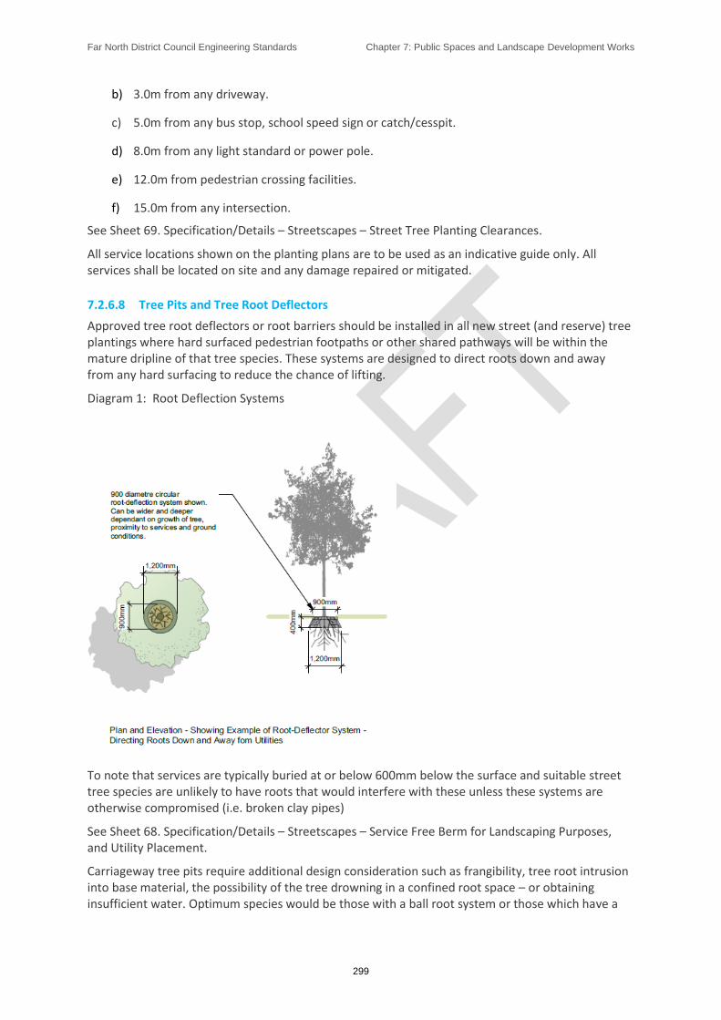
Far North District Council Engineering Standards Chapter 7: Public Spaces and Landscape Development Works
299
b) 3.0m from any driveway.
c) 5.0m from any bus stop, school speed sign or catch/cesspit.
d) 8.0m from any light standard or power pole.
e) 12.0m from pedestrian crossing facilities.
f) 15.0m from any intersection.
See Sheet 69. Specification/Details – Streetscapes – Street Tree Planting Clearances.
All service locations shown on the planting plans are to be used as an indicative guide only. All services shall be located on site and any damage repaired or mitigated.
7.2.6.8 Tree Pits and Tree Root Deflectors
Approved tree root deflectors or root barriers should be installed in all new street (and reserve) tree plantings where hard surfaced pedestrian footpaths or other shared pathways will be within the mature dripline of that tree species. These systems are designed to direct roots down and away from any hard surfacing to reduce the chance of lifting.
Diagram 1: Root Deflection Systems
To note that services are typically buried at or below 600mm below the surface and suitable street tree species are unlikely to have roots that would interfere with these unless these systems are otherwise compromised (i.e. broken clay pipes)
See Sheet 68. Specification/Details – Streetscapes – Service Free Berm for Landscaping Purposes, and Utility Placement.
Carriageway tree pits require additional design consideration such as frangibility, tree root intrusion into base material, the possibility of the tree drowning in a confined root space – or obtaining insufficient water. Optimum species would be those with a ball root system or those which have a

Far North District Council Engineering Standards Chapter 7: Public Spaces and Landscape Development Works
300
deep rooting habit with minimum surface roots. Species will be site specific according to conditions and soil type.
See Sheet 67. Specifications/Details – Streetscapes - Tree Pits and Tree Planting within the Road Corridor.
7.3. Construction
7.3.1. Introduction
Following construction standards and recommended procedures will ensure that all landscaping is to an acceptable standard prior to final inspection and release of the bond (if a bond is required).
It is the Developer/Contractor responsibility to ensure that the landscaping meets these required standards at the termination of the maintenance period. The developer/contractor is responsible for the routine maintenance and replacement of the planting, including dead wooding, weed control, mulching, replacing dead trees, shrubs, and plants, and watering for the period from planting to the issue of a section 224 completion certificate under the Resource Management Act or contract maintenance period.
7.3.2. Protecting Existing Vegetation and Trees
7.3.2.1 Root Protection Distances
A tree root protection zone must be established by an arborist or otherwise qualified person before any work is carried out around tree to be retained. A sufficient amount of the root system to ensure the survival of the tree during the construction phase must be taken into account. This will also be dependent on the following factors:
o Tolerance of the tree to root disturbance base on species, age and condition.
o Compressibility of the soil.,
o Site topography and drainage.
o The use of the site once work is complete.
Diagram 2: Root Protection Distances

Far North District Council Engineering Standards Chapter 7: Public Spaces and Landscape Development Works
301
7.3.2.2 Below Ground Works
If installation is required under existing trees and vegetation, then trenchless technology should be considered. If this is not practicable, advice from a qualified Arborist is required to minimise damage to the vegetation.
No works are to commence within 20m of historic/protected or notable trees without written approval from Council’s parks staff. Council may require that an Arborist monitor works in or around these trees.
7.3.2.3 Assessment Prior to Works
Prior to undertaking any work within the dripline of retained vegetation an on-site assessment of the work proposed shall be undertaken by the Arborist.
Where heavy machinery would be operated, driven or sited within the dripline of any retained tree temporary protective fences shall be erected between the tree and the work area so as to protect the tree from damage. The position and composition of the protective fences shall be established prior to works commencing, and once erected, approved by the Arborist prior to the commencement of any site construction works. The temporary protective fences shall be strong and appropriate to the degree of construction works taking place on the site. The protective fences shall be a solid barrier, which cannot easily be picked up and moved. The protective fence shall be at least 1.5m high.
No works, storage of materials, cement/concrete washings and leaching of chemicals, trenching or alteration of soil grade shall occur within those areas demarcated by a temporary protective fence. The temporary protective fences shall remain in place throughout the duration of the construction works. The position of the protective fence shall not be altered without the prior consent of the Arborist.
7.3.2.4 During Works
Within the root zone of retained trees:

Far North District Council Engineering Standards Chapter 7: Public Spaces and Landscape Development Works
302
a) The removal of any existing footpath, kerb and channels, when within the root zone of retained trees, shall be carefully undertaken so as to cause no more than minor damage to the retained trees.
b) All roots of greater than 35mm in diameter shall be carefully worked around and protected. No such roots shall be removed, except:
• where no practicable alternative to removing the root exists and;
• where this would have a no more than minor detrimental effect on the tree and this is the supported professional opinion of the Arborist. Any such removal shall be undertaken by the Arborist.
c) Exposed roots of greater than 50mm shall be covered with 50mm of sand and rootzone areas shall be immediately covered with a suitable permeable Geotextile fabric immediately after removal of existing concrete.
d) Prior to laying of basecourse the underlying roots shall be protected by laying a suitable permeable Geotextile fabric over the soil surface.
e) There shall be no positioning (sitting or driving through) of heavy machinery unless this is on an existing hard surface (concrete or paved) or temporary hard surface.
f) The temporary hard surface methodology must be approved in writing by a qualified Arborist or the Council’s engineer. It shall be constructed by laying geo-tech matting on the surface, 100mm weed free mulch or similar soft material on a hard surface placed on the soft material, i.e. sheets of plyboard.
All roots that are severed shall be pruned cleanly back to the surface of the excavation using sharp handsaw or secateurs. All exposed or severed roots shall be kept damp (using hessian cloth or similar) until the excavated area is backfilled.
No damage shall be done to the trunk and above ground parts of any tree that is to be retained.
Any pruning required to facilitate the works to retained trees shall be undertaken by the Arborist.
7.3.3. Reserves Specimen Tree Location
All reserve plantings shall be marked out on site, and approved by Council, prior to planting works commencing.
7.3.4. Site Preparation
All irrigation and drainage work, utilities installation, signs or landscape structures shall be completely installed prior to planting.
7.3.4.1 Excavation and Bedding of Planting Areas
Excavation shall be carried out where necessary to achieve either of the required soil profiles where depths indicated are post consolidation.
See Sheet 71. Specifications/Details - Landscape Bedding Profiles and Preparations.

Far North District Council Engineering Standards Chapter 7: Public Spaces and Landscape Development Works
303
7.3.4.2 Landscape Planting
All waste material shall be removed from site.
The exposed subgrade shall be trimmed and levelled so that no part of the subgrade shall be above the required depth of cut.
7.3.5. Soil
Topsoil, both imported and existing on site, shall be:
• a loam soil of good quality
• free draining
• free of weeds and contaminates
• free of building materials and debris
• screened
• healthy; and
• contain no pans
All new planting areas on existing topsoil shall be deep ripped to a minimum of 300mm prior to planting.
7.3.6. Tree Pits
Saw-cutting of existing seal where required shall be undertaken between 250mm to 300mm from the back of the kerb. The design and measurements must be approved by Council prior to works commencing. The cut line shall be parallel the kerb lines wherever possible. All cut-outs are to be square and to be a minimum 1.0m x 1.0m dimension.
Planting holes shall be excavated, according to the following minimum specification:
Table 5: Tree Pits Design Criteria
TREE TYPE TREE GRADE PIT SIZE PIT DEPTH
Street Trees 45 litre (PB95) 1.0m diameter 1.0m
Reserve Tree 45 litre (PB95) 2.0m diameter 750mm
Reserve Tree 90 litre 2.5m diameter 1.0m
See Sheet 67. Specifications/Details – Streetscapes - Tree Pits and Tree Planting within the Road Corridor.
The sides of the planting hole shall also be loosened by forking to 150mm minimum, and the surrounding ground to two times the root ball diameter shall be ‘forked’ over to reduce compaction.
Where topsoil is unsuitable for backfilling, imported or modified topsoil for backfilling shall be used. The imported topsoil shall be a free draining loam of a quality and subject to inspection by Council prior to placement.
Far North District Council Engineering Standards Chapter 7: Public Spaces and Landscape Development Works
304
Modified backfill soil shall consist of a homogenous mixture of the following to min 500mm deep.
• Parts by volume of good quality, friable topsoil from the site or imported.
• Three parts by volume of Council approved compost.
• Two parts by volume of coarse river sand.
The base of the planting hole shall be forked to a minimum depth of 200mm and any stones over 50mm diameter or poor-quality subsoil shall be removed from the hole.
See Sheet 70. Specifications/Details – Reserves and Streetscapes - Tree Planting Methods.
7.3.7. Grassing, Sowing and Turfing
This section covers the preparation and sowing of any new grassed areas or those requiring reinstatement or turfing of such areas. It includes berms, lawns and embankments.
7.3.7.1 Preparation for Sowing or Turfing
The following conditions apply:
• Grassing and fertilizing shall be carried out over all existing grassed areas disturbed by contract activity and other specified areas which may require reinstatement.
• Excessive compaction of subsoil in existing grassed areas shall be relieved to achieve satisfactory long-term growing conditions.
• All topsoil removed to permit contract works to be carried out shall be stockpiled for reuse.
• All new grass areas shall be built on soil prepared to industry best practice standards.
• Sloped areas shall be neatly contoured into adjoining grassed areas.
• Perennial weeds shall be controlled with industry best practice methods.
7.3.7.2 Grass Sowing
The following requirements apply:
• The seed mixture shall be an industry standard quality.
• Suitable grass mixtures include Kikuyu, Rye and Couch which provide differing levels of drought tolerance, visual appeal, proven wear and lower maintenance.
• On large areas the seed shall be “check” sown in at least two directions and surface rolled with suitable flat roller.
• On small areas the grass seed shall be evenly applied and raked into the soil.
7.3.7.3 Establishment of Sown Areas
The following requirements apply:
• Newly established grass shall be protected from damage by pedestrian and vehicular traffic until grass has reached a self-sustaining state.

Far North District Council Engineering Standards Chapter 7: Public Spaces and Landscape Development Works
305
• Grassed areas shall be watered as required to achieve an efficient germination of the seed.
• Newly grassed areas shall be maintained with regular mowing (90mm-30mm) ensuring that all clippings are removed from adjacent hard surfaces.
All grassed areas adjacent hardscape - such as paths, kerbs, hardstand areas – to ensure base of grass is flush with adjacent path. If base of grass level is 30mm lower or more than adjacent hardstand, grass will need to be removed min 1m back from path, soil put back in, levelled and re-consolidated to spec and grass res-own to correct level. If less than 30mm top dressing at 10mm each time, over time will be acceptable until the correct level is achieved.
7.3.7.4 Turf/Instant Turf
The following requirements apply:
• The turf shall be of good quality in line with industry standards.
• Suitable grass mixtures include Kikuyu, Rye and Couch which provide differing levels of drought tolerance, visual appeal, proven wear and lower maintenance.
• Turf shall be installed and maintained in accordance with supplier’s requirements.
• Areas of turf where there has been a poor establishment shall be re-laid.
7.3.7.5 Sloped Areas
In all sites, except natural gully systems, where the slope gradient is steeper than 1:3 (one metre high by three metres long), it is preferable that the embankment is either scarified or grooved on an angle to a depth of 200mm, from the top of the bank to the base. This assists topsoil adhesion and prevents separation of the top 150mm topsoil from the base material due to gravity and/or glazed/planning of base material.
See Sheet 71. Specifications/Details - Landscape Bedding Profiles and Preparations.
7.3.8. Street Tree Planting
7.3.8.1 Timing
All tree planting shall be undertaken between May and August.
All trees shall be planted on the day of delivery to the site.
Council shall be provided with not less than five days’ notice of dates upon which planting will commence.
7.3.8.2 Layout
Trees shall be planted in the locations shown on the planting plans and in accordance with these specifications. Unless otherwise indicated on the planting plans all plants shall be planted centrally within the road berm.
See Sheet 69. Specification/Details – Streetscapes – Street Tree Planting Clearances
7.3.8.3 Tree Root Barriers
Root barriers shall be installed prior to tree planting in almost all circumstances with exception berms that contain no utilities. The location of root barriers shall be as specified and centred around the plant stem.
Far North District Council Engineering Standards Chapter 7: Public Spaces and Landscape Development Works
306
Refer Diagram 1: Root Deflection Systems
7.3.8.4 Street Tree Mulching
All street trees must have a minimum 1.0m diameter mulching circle from the tree trunk.
Mulch shall be well rotted organic tree mulch. Mulch shall be free of foreign debris such as rocks and plastic.
Mulch shall be applied to a depth of no more than 150mm after planting. The final settled depth shall be no more than 120mm and no less than 100mm. Ensure that mulch is welled up to ground level around the tree trunk.
7.3.9. Irrigation and Fertilising
7.3.9.1 Irrigation
During installation and establishment, the soil in all planting areas moisture shall be retained to ensure active plant growth throughout the growing season (September – May). To achieve a high level of site presentation or in areas of annual bedding display planting, irrigation systems may be required to achieve this.
Where an irrigation system is required to be installed, ‘Toro’ brand or a similar approved brand shall be used. The system shall be capable of providing a minimum soil moisture level of 50% to 200mm depth, throughout the planted areas or within the dripline of trees specified. It shall be capable of fully re-wetting the root zone to 200mm depth when the irrigation is applied; and shall be fully automated to operate between 1:00am and 6:00am when moisture levels drop below 50%.
7.3.9.2 Passive Street Tree Irrigation
When surrounded by hard surfaces or as specified, a street tree shall have a 1900mm long section of perforated Novaflow, or similar, perforated pipe inserted into the tree pit. The Novaflow is to run down one side of the tree pit, under the intended root ball and up the opposite side of the tree pit to be level with the ground surface. The other end is to extend above the intended mulch layer by 20mm. Both ends of the pipe should be capped. Underground irrigation systems can be used instead of manually watering.
7.3.9.3 Fertilising General
Generally, some form of fertiliser shall be applied to planting depending on the soil type. For shrubs and trees, all fertiliser shall be well mixed with the backfilled soil. For bedding or groundcover all fertiliser shall be well mixed with the site topsoil prior to planting. Fertilisers shall be either an approved pelletised natural or organic fertiliser or an approved synthetic fertiliser.
An exception to these approved pelletised natural and organic fertilisers or approved synthetic fertilisers is for the Proteaceous species and ferns which should on no account be fertilised with Phosphate (P) containing fertilisers.
7.3.9.4 Street Trees Fertilising
All specimen tree plantings shall have two-year slow release fertiliser tablets installed at the time of planting.
7.3.9.5 Grass Sowing and Turf
All fertilisers shall be delivered to the site immediately before they are required for spreading and shall be thoroughly mixed on the site. Council may prohibit the use of any fertilisers which have

Far North District Council Engineering Standards Chapter 7: Public Spaces and Landscape Development Works
307
deteriorated because of interaction, wetting, etc. Fertilisers shall be lightly harrowed into the topsoil, 2-3 days prior to seed sowing, at the following rates at 200kg/ha.
Table 6. Equation: Grass Sowing Rates
Fertiliser Application rate
30% Potassic Superphosphate 150 kg/ha (15g/m2)
Sulphate of Ammonia 50 kg/ha (5g/m2
This shall be followed one month after sowing, with an application of
Di-ammonium Phosphate (DAP) 100 kg/ha.
7.3.10. Quality Control
7.3.10.1 Plant Grades, Species and Quality
General Plant Grades
All plants shall be supplied true to the species and grades specified on the approved landscape plans and fill the specified planter bag. All street trees, unless specified otherwise, shall be of a minimum grade of 45 litres (Pb95) with a minimum 60mm caliper at 1m from ground level.
All other stock shall be of minimum 2 litre grade for groundcover and 3 litre grade for shrubs.
General Plant Species and Quality
a) Trees shall be selected from Council’s approved tree species list. No substitution of species or grade shall be made without the written approval of Council.
b) All plant material supplied shall be clearly labeled.
c) Council shall be provided with not less than ten working days’ notice of dates upon which plants are to be delivered on site, so that arrangements can be made for quality inspection and confirmation of identification of plant material.
d) Trees shall be well branched, symmetrical and of typical habit for the species.
e) All plants shall be nursery stock of good form, healthy and vigorous with strong fibrous root systems and free of all pests and diseases.
f) All trees shall be supplied with the central leader intact - no pruning of the central leader shall have taken place. All torn or damaged roots shall be pruned before dispatch. All stock shall be well rooted but not root bound. Open ground stock shall be well-wrenched.
g) All root balls and containers shall be free of all weeds. Plants shall be well 'hardened -off' prior to supply.
h) All plants and their roots shall be maintained in a moist environment, protected from adverse conditions such as drying winds, frost or water logging. All roots must be covered during transit and storage to prevent desiccation or damage.
7.3.10.2 Street Tree Grades, Species and Form
All street trees, unless specified otherwise, shall be of a minimum grade of PB 95/or 45litres and be first grade nursery specimens. No substitution of species or grade shall be made without the written approval of Council.

Far North District Council Engineering Standards Chapter 7: Public Spaces and Landscape Development Works
308
Trees shall be well branched, symmetrical and of typical habit for the species. All plants shall be nursery stock of good form, healthy and vigorous with strong fibrous root systems and free of all pests and diseases.
All trees shall be supplied with the central leader intact, whereby no pruning of the central leader shall have taken place. All torn or damaged roots shall be pruned before dispatch.
All stock shall be well rooted but not root bound. All root balls and containers shall be free of all weeds.
7.3.11. Weed and Litter Control
7.3.11.1 Litter Control
The planting area shall be kept clear of all rubbish, including domestic and building materials.
7.3.11.2 Chemical Applications for Weed and Pest Control
All chemical application on planted areas shall be carried out by qualified, trained personnel and according to NZS 8409:2004 – Management of Agrichemicals, any relevant local Herbicide Policy and manufacturers’ requirements.
All spraying operations shall be carried out in windless, dry conditions, when rain is not imminent for at least 12 hours and at times which minimise possible hazards or disruption to the public, animals or other beneficial fauna. Care shall be taken to prevent spray drifting onto non-target areas or plants and comply with notification requirements as required by the proposed Northland Regional Plan.
Herbicides may be used to control weeds or excess grass growth over structures, surfaces or into planting areas.
All trees in grassed areas shall have a weed release spot spray applied between four and six months after planting. General weed control shall be carried out whenever necessary to maintain the planting weed-free.
Chemical weed control in planting areas shall be kept within the edge of the planting beds, within a maximum of 500mm of tree trunks, within 50mm of the edge of any undefined mulch surface, and within 50mm of any posts or the base of any landscape structures.
7.3.12. Mulching
Unless otherwise approved by Council, all new planting areas shall be mulched. All care shall be taken in placing the mulch so as to protect the plants and any irrigation system, ensuring that no plant canopy is covered by mulch post-installation. All damage to the plants or irrigation system shall be rectified.
7.3.12.1 Site Specific Mulch Applications
Flat Site Mulch
On sites flatter than a 1:3 grade (1.0m high by 3.0m metres long), quality 5B/shredded cambian bark mulch or ‘Forest Floor’ shall be spread evenly to a depth of 100mm over the planted area, creating an inverted cone hollow around each plant stem. The mulch shall be supplied as scheduled, clean and free of soil, sawdust and wood preservatives. A sample may be required to the District Council for approval prior to spread.
Steep Site Mulch
Far North District Council Engineering Standards Chapter 7: Public Spaces and Landscape Development Works
309
On slopes steeper than 1:3, mulching for weed control shall consist of Council approved matting. The matting shall be a single layer of fully biodegradable mulching fabric or material without synthetic geonet or synthetic geotextile content with at least 1000gsm density. The mulching fabric shall have a minimum 24-month life expectancy and be fully biodegraded into soil within six years. It shall be installed according to manufacturer's instructions prior to planting, ensuring that the mulch will not uplift due to inundation, winds or from animals such as Pukeko.
At Council’s discretion, mat rounds may be used instead of matting. These shall be a minimum 500mm diameter and have the same characteristics as the mulch fabric. Each round shall have 8 pins: 4 pins equidistant near the outer edge and 4 pins around the plant stem.
On steep slopes with erosion issues that are receiving planting, biodegradable netting with no geotextile or geonet content shall be used at the District Council’s discretion. The netting will have an expected lifespan of at least 36 months. This shall be placed on top of the mulch matting and shall be installed according to manufacturer’s instructions. The netting is not intended to suppress weeds and shall be used in conjunction with mulch matting or rounds.
See Sheet 71. Specifications/Details - Landscape Bedding Profiles and Preparations.
7.3.13. Staking, Fencing and Protection
Specimen and Street Trees
Newly planted specimen trees shall be staked with two 50 x 50 x 1.8m hardwood or rough sawn pine H4 stake with at least one third of their length (600mm) in the ground and at least 1.0m exposed minimum, or as specified on the approved plan. One flexible hessian tie per stake shall be attached to secure the tree. Ties shall be tensioned to avoid chafing of the tree against the stakes but with enough play for the tree to move in the wind. All ties shall be fixed to the stakes. Any other stakes including those against the main stem shall be removed.
Ties shall be fixed to the outer stake face with a minimum of four staples in a square pattern.
All stakes shall be inserted to avoid hitting the root ball. Stakes shall be at least 350mm away from the tree trunk and no more than 500mm away.
7.3.14. Pruning
Pruning should be carried out in accordance with acceptable arboricultural and horticultural practices (ideally by a New Zealand Arboricultural Association registered member) with oversight from Council’s parks team.
See Sheet 70. Specifications/Details – Reserves and Streetscapes - Tree Planting Methods
7.4. Completion of Works
7.4.1. Completion
Works to be carried out under the defect’s liability period include routine maintenance of the landscape planting works i.e. weeding, litter removal, mulching, watering and replacement of dead or diseased plants.
Council may periodically check the site to ensure that maintenance requirements are being met. Should any defects be identified, the defects shall be remedied or mitigated within one month.

Far North District Council Engineering Standards Chapter 7: Public Spaces and Landscape Development Works
310
7.4.2. As-built Information
Upon completion of construction work, copies of As-built plans and data attributes of the completed works shall be provided.
Separate plans are required for wastewater, stormwater, and water supply.
Responsibility for providing the plans and associated data shall lie with:
a) The Developer, in the case of land development (urban and industrial subdivision).
b) The Contractor, in the case of works constructed for Council under contract to Council.
7.4.3. Works Clearance Inspection
After completing all proposed works Council shall be provided notice at least seven working days prior to the proposed commencement of the defects liability period and shall be available for a joint pre-defects’ liability period inspection.
7.4.4. Defects Liability Period Final Inspection
The Developer/Contractor shall request acceptance from Council of the asset and its ongoing maintenance at least 7 working days prior to the end of the defect's liability period.
The General Planting Defects Requirements apply to all planting, except where Street Trees and Grass Turf have been planted.
7.4.5. Street Trees Defects Liability Period
The planting defects liability period shall be 2 years from works clearance or practical completion (or as defined in the resource consent) and acceptance of the landscape planting works by Council or upon release of any implementation bond held for uncompleted landscaping.
A copy of the as-built plan recording any variation from the approved landscape planting plans shall be provided to Council.
7.4.6. General Planting Defects Liability Period
The planting defects liability period shall be 2 years from works clearance or practical completion (or as defined in the resource consent) upon release of any implementation bond held for uncompleted landscaping.
During and at the end of the defect’s liability period, the following minimum standards are required:
• All top-soiled areas prior to planting and mulching shall be weed-free.
• All planted areas shall be kept weed-free.
• All planted areas including street trees shall be replenished with the approved mulch.
• All trees and other planting shall be vigorous and healthy, free of disease and free of dead growth or dead flowers.
• If planting is to take place during drier, summer months, provision of temporary on-site irrigation should be discussed with Council.

Far North District Council Engineering Standards Chapter 7: Public Spaces and Landscape Development Works
311
• The planting has become established. Any plants failing during this period shall be replaced to the specification, to ensure adequate establishment of the planting.
• The plant growth shall have been trimmed to the extent and height required for any visibility splays.
• All tree stakes and ties shall be intact and correctly installed.
Replacement Planting
All replacement plants shall have been successfully established for at least three months prior to the final defects check. Council reserves the right to request replacement records that preferably include dated digital photographic evidence to verify installation dates.
7.4.7. Fencing and Landscape Structure Defects Liability Maintenance
During and at the end of the defect's liability period the following minimum standards shall be maintained
• All permanent or temporary landscape structures shall be structurally sound, safe, functional or operational and in a presentable finished form
• Paintwork and other finishes shall be maintained in a clean and presentable finished form. Bolts and other fixtures shall be maintained sound and without loose parts or rough edges
• All structures shall be free of litter, graffiti, grime, weeds and plant growth or any other foreign matter
• Borders, footing edges or paving shall be maintained so that no more than 25mm of grass or other vegetation is allowed to encroach. Vertical elements without mowing edges shall have vegetation maintained clear of the structure by no less than 25mm and no more than 75mm
7.4.8. Grassing and Turf Defects Liability Period
After initial establishment, during and at the end of the defect's liability period, the following minimum standards shall be maintained:
• All kerb and channeled verges shall have grass growth no more than 50mm high, non-kerb-and-channeled verges shall have grass growth no more than 200mm high and banks shall have grass growth not more than 250mm high.
• The sward shall be maintained in a healthy, weed-and-disease free state without bare patches.
• Trees and other plantings shall be protected from damage by maintenance or mowing operations and if damaged shall be reinstated within one week of the damage occurring.
• Maintenance and mowing operations shall be carried out at times which minimise disruption to the public.
• Maintenance and mowing operations shall be carried out only in conditions with equipment that ensures maintenance of good soil structure, minimum deformation of ground surfaces and on-going establishment of the grass sward.
• Litter shall be removed prior to commencing maintenance or mowing operations. Highly visible shredded litter shall be removed following maintenance and mowing.

Far North District Council Engineering Standards Chapter 7: Public Spaces and Landscape Development Works
312
• Grass clippings, when not required to be collected during mowing, shall be spread evenly over the sward.
Table 7: Minimum General Landscape Maintenance Schedule during Defects Liability Period

Far North District Council Engineering Standards Chapter 8: Electricity, Telecommunications and Gas
313
Chapter 8: Electricity, Telecommunications and Gas

Far North District Council Engineering Standards Chapter 8: Electricity, Telecommunications and Gas
314
8.1. INTRODUCTION ........................................................................................................................ 315
8.1.1. Description and Expectations ..................................................................................... 315
8.1.2. Objectives ................................................................................................................... 315
8.1.3. Reference Documents ................................................................................................ 315
8.2. DESIGN ..................................................................................................................................... 316
8.2.1. General Requirement ................................................................................................. 316
8.2.2. Reticulation Layout ..................................................................................................... 317
8.2.3. Utilities on Bridges ...................................................................................................... 317
8.2.4. Plans ............................................................................................................................ 317
8.3. CONSTRUCTION ....................................................................................................................... 318
8.3.1. Underground Cabling .................................................................................................. 318
8.3.2. Materials ..................................................................................................................... 318
8.3.3. Ducting ........................................................................................................................ 318
8.4. COMPLETION OF WORKS ......................................................................................................... 319
8.4.1. As-Built Plans .............................................................................................................. 319

Far North District Council Engineering Standards Chapter 8: Electricity, Telecommunications and Gas
315
8.1. Introduction
8.1.1. Description and Expectations
This section sets out the requirements for network utilities that are not owned or managed by the District Council: electricity, telecommunications/data and gas (compressed natural gas).
The District Plan has varying requirements for the provision of network utilities depending on the Environment. There is no requirement for gas to be reticulated in future subdivisions, whereas there is an expectation that electricity and telecommunication are reticulated in urban and some rural and coastal areas.
The Developer shall liaise with the relevant Network Utility Operator(s) as necessary for the development and as required by the District Plan. The cost of this work, necessary legalization and transferring of land, installation work, and amendments to existing utilities shall be the responsibility of the Developer unless otherwise agreed in writing with the respective Network Utility Operator and/or the District Council.
8.1.2. Objectives
To ensure that each network is located so as to be capable of servicing the intended users.
To ensure that networks are designed to acceptable urban design, landscaping and engineering standards
To ensure all networks are laid underground unless not required by the District Plan
To ensure that any network that is to be located above ground within the road reserve shall be located clear of footpaths, cycleways, accessways and vehicular sightlines.
8.1.3. Reference Documents
The following documents are referenced in this Chapter;
8.1.3.1 Statutory
Operative District Plan and Proposed District Plan
8.1.3.2 New Zealand Standards
NZS 5258:2003 - Gas distribution networks
8.1.3.3 Other Referenced Documents
NZ Utilities Advisory Group: National Code of Practice for Utility Operators' Access to Transport Corridors 2015
Any Relevant Regional Plan
NZECP 34:2001 - New Zealand Electrical Code of Practice for Electrical Safe distances
Telecommunication Facilities Regulations 2008
Resource Management National Policy Statement (NPS)
NES for Electricity Transmission Activities Regulations 2009.

Far North District Council Engineering Standards Chapter 8: Electricity, Telecommunications and Gas
316
Electricity (Hazards from Trees) Regulations 2003.
WorkSafe NZ Publication; Guide for Safety with Underground Services
WorkSafe NZ Publication; Guide for Safety with Underground Services
8.2. Design
8.2.1. General Requirement
Where network utilities shall be installed as part of the subdivision development, a point of supply shall be provided to the boundary of each lot, or at the discretion of the Network Utility Operator it shall be provided at a selected location within 10m of each lot. Ducting for any network utility may be laid at the discretion of the Network Utility Operator at the time of subdivision. All cables and pipes shall be underground, (preferably installed during road construction) as specified in the District Plan.
Where an electricity or telecommunications network is not to be installed as part of the subdivision, the District Council will require the use of a ‘no electricity supply encumbrance’ or ‘no telecommunications supply encumbrance’ registered on the affected land title(s).
The design of network utility reticulation and service connections shall be undertaken by a suitably qualified designer for each utility type.
General Requirement clause a, is to be developed specifically for Land Use scenarios.
The Developer shall be responsible for:
i. All arrangements with the Network Utility Operator for the supply and installation of the relevant utilities,
ii. Ensuring that the network utility is installed as part of the subdiv ision works and in accordance with the ES, and
iii. Obtaining certification from the relevant Network Utility Operator that the network utility has been installed in accordance with their requirement and the ES
iv. Providing confirmation with subdivision applications from a network utility operator that electricity and telecommunications supply can be provided to each lot.
v. Confirmation from network utility operator that electricity and telecommunications supply is suitable for the land use is still under consideration.
vi. The installation of fibre telecommunication connections where it is available in urban zones or zones used predominately of residential use. If fibre is not available a copper telecommunication connection is to be installed instead.
The point of supply, such as distribution pillars and similar, shall be located in the road reserve boundary of each lot and shall not be located where they are likely to

Far North District Council Engineering Standards Chapter 8: Electricity, Telecommunications and Gas
317
cause interference with access construction at the common boundary of access ways onto roads. Where telecommunication utilities are to be installed via private access way ducting is to be installed prior to construction of the access.
It is the incoming owner’s responsibility (not withstanding prior arrangements) to meet the costs of any internal (within the lot) network utility reticulation and/or any network utility upgrade that may be necessary to supply loads above that designed for.
Where applicable on private land, easements shall be registered as and when required by the Network Utility Operator over new and existing network utility cables, lines, and plant in favour of the Network Utility Operator to ensure the security of supply.
Sites for transformers, gas regulators and other equipment and facilities shall be provided where required and positioned and secured to minimise any hazard. They be located in a utility reserve outside the road reserve unless Specific Approval is obtained
Any works being undertaken on a Council legal road by the public will require approval from Council and accompanied by a Temporary Traffic Management Plan prior to works commencing.
8.2.2. Reticulation Layout
The position of utilities in the road shall conform with the standard layout shown in the Sheet 29 and Sheet 30.
Network Utility Operators may require their utilities to be spaced at greater distances from the minimum specifications, in which case the most restrictive requirements will govern the clearances applied.
The Developer is responsible for ensuring that all Network Utility Operator’s requirements are achieved.
The following shall also apply:
All utilities shall run parallel to the surveyed road boundary line, and
Wherever the utility crosses a carriageway, the utility shall be installed in a duct. The duct shall conform to the requirements of the Network Utility Operator. Where the duct can be installed before the road base is constructed the duct can be installed by open trenching otherwise the duct shall be installed using trenchless methods.
8.2.3. Utilities on Bridges
The installation of utilities on bridges and the approach route shall be subject to Specific Approval.
All utilities shall be enclosed in ducts mounted in positions approved by the District Council.
8.2.4. Plans
Plans of utilities shall be consistent with the drawing standards outlined in Appendix G Drawing
Standards.

Far North District Council Engineering Standards Chapter 8: Electricity, Telecommunications and Gas
318
Note: Copies of the plans of the development shall be forwarded by the Developer to all of the affected Network Utility Operators at an early date to facilitate the design of the reticulation.
In preparing the Engineering Plans the Developer shall consider the requirements of the Network Utility Operator and the TA corridor manager for:
Minimum cover to cables and pipes,
The Network Utility Operator’s desired position for the cables and pipes within the road berm as agreed with the TA corridor manager,
The minimum separation distances between power or telecommunication cables, and gas and water assets,
The width of berm which shall be clear of other utilities and obstructions to enable efficient cable laying operations,
The requirements of NZS 5258:2003,
The requirements of the National Code of Practice for Utility Operators’ Access to Transport Corridors 2015, and
The minimum separation distances between overhead power lines and buildings, structures and earthworks outlined in the NZECP 34:2001.
8.3. Construction
8.3.1. Underground Cabling
Underground cabling shall be achieved by the most appropriate method considering the following:
nature of the subsoils,
the potential damage to other infrastructure, and
the state of completion of other infrastructure
with the method used subject to the approval of the Corridor Access Manager.
Where open trenching is used, all backfilling and compaction of trenches shall be undertaken in accordance with the ES and to the satisfaction of the Corridor Access Manager.
8.3.2. Materials
Materials and sizes of ducts and pipes shall comply with the requirements of the Network Utility Operators and the colours shall be in accordance with the Work Safe NZ publication Underground services - Guide for safety with underground services.
8.3.3. Ducting
The following shall apply:
Ducts shall be laid in straight lines, parallel to or at right-angles to the kerb and/or property boundaries with horizontal tolerances of horizontal ±300mm and vertical ±100mm.

Far North District Council Engineering Standards Chapter 8: Electricity, Telecommunications and Gas
319
Ducts shall be installed with draw-wires and end-caps where the network utility reticulation or connection is likely to be installed after roads, footpaths, entranceways and the like are constructed. This minimises the need for trenching through the new surfaces. If cables shall be installed after completion of paved areas and where ducts have not been provided then trenchless installation methodologies shall be required.
The duct size, colour and installation shall comply with the network utility provider specifications and the WorkSafe NZ publication; Guide for Safety with Underground Services.
8.4. Completion of Works
8.4.1. As-Built Plans
Upon completion, the Developer shall accurately record ‘as-built data’ for network utility reticulation installed for the development, which shall be kept as a permanent record by the Network Utility Operator in a format suitable for use by others.

Far North District Council Engineering Standards Appendices
320
Appendices

Far North District Council Engineering Standards Appendices
321
APPENDIX A DESIGN FOR SURGE AND FATIGUE ................................................................................ 322
APPENDIX B ES-SEW1 ......................................................................................................................... 327
APPENDIX C ES – PS1 .......................................................................................................................... 333
APPENDIX D ES – PS4 ......................................................................................................................... 335
APPENDIX E ES-PO1............................................................................................................................ 337
APPENDIX F PERMEABILITY TEST SHEETS .......................................................................................... 340
APPENDIX G DRAWING STANDARDS ................................................................................................. 343
APPENDIX H EXAMPLE AS-BUILT DRAWINGS .................................................................................... 347
APPENDIX I ASSET ATTRIBUTES .......................................................................................................... 357
APPENDIX J CHECKLIST FOR SUPPORTING INFORMATION ................................................................ 374
APPENDIX K LIST 1. RESERVE PLAYGROUNDS - APPROVED PLAYGROUND EQUIPMENT AND SURFACING SUPPLIERS AND INSTALLERS .......................................................................................... 380
APPENDIX L LIST 2. RESERVES AND STREETSCAPES - APPROVED COMMON LANDSCAPE FURNITURE PRODUCTS AND SUPPLIERS. .............................................................................................................. 381
APPENDIX M LIST 3. RESERVES AND STREETSCAPES - SUITABLE SHRUB AND PLANT SPECIES FOR RESERVE AND STREETSCAPE PLANTING ............................................................................................ 389
APPENDIX N LIST 4. RESERVES AND STREETSCAPES - SUITABLE TREE SPECIES FOR RESERVE AND STREETSCAPE PLANTING. ................................................................................................................... 390
APPENDIX O SPREADSHEET 1. PUBLIC TOILETS – GOLD AND SILVER STANDARDS FOR NEW PUBLIC CONVENIENCES .................................................................................................................................. 391

Far North District Council Engineering Standards Appendices
322
Appendix A Design for Surge and Fatigue
A1 Introduction
All pipelines are subjected to pressure variations during their lifetimes. Some of these pipelines, e.g. rising mains, will experience significant and regular pressure surges, while others may be subjected only to minor diurnal pressure variations.
Rapid pressure fluctuations and surges generally result from events such as pump start -up and shutdown, or rapid closing or opening of valves, including ‘slamming’ of air valves as can happen during venting of bulk air from pipelines.
For the purposes of the FNDC ES, a pressure surge is defined as a rapid, short-term pressure variation. Surges are characterised by rapid, high-pressure rise rates, with minimal time spent at the peak pressure. Surge events usually consist of a number of diminishing pressure waves that cease within a few minutes.
The frequency and magnitude of the pressure transients affects the choice of pipe pressure class. Ensure that the following aspects are considered when designing for surges and fatigue;
That the maximum and minimum pressures are within acceptable limits for the pipe and fittings for all surge events (including infrequent events such as power failure, emergency shut-down, rapid closure of fire hydrants),
Consider the potential for fatigue and select the pipe pressure class accordingly, to allow for frequent repetitive pressure variations, and
The pipe and the quality of installation and their influence on the fatigue resistance of the pipe.
The following sections provide a methodology for dealing with surge and fatigue, so that pipes are adequately designed to provide the 100 year design life that is required.
The PIPA Guidelines may also be used, specifically the following;
POP010A – Polyethylene Pressure Pipes Design for Dynamic Stresses
POP101 – PVC Pressure Pipes Design for Dynamic Stresses
These may be found at https:/www.pipa.com.au/technical/pop-guidelines.
A2 Pressure Surge Events
A surge analysis is required to check whether damaging pressure surges (or surges that could cause customer complaint) could occur in a system. The level of detail of the surge analysis should be appropriate to the pipeline. For example, a reticulation pipeline may require only consideration of rapid closure of fire hydrants and conservative selection of pipe pressure rating.
Pipelines that may be subjected to more severe surge effects e.g. rising mains, areas close to control valves (reservoir inlet valves and pressure reducing valves) and where specified by Council, require a more detailed level of analysis, or the selection of pipe materials that are highly resistant to surge and fatigue issues.
The source(s) of significant pressure surges in a water system should be identified and included in any surge analysis. Mitigating measures may be needed to minimise any surges generated, and any surge control devices must be designed accordingly. As a minimum, such a surge analysis should consider;

Far North District Council Engineering Standards Appendices
323
Identified causative scenarios (e.g. power failure, pump trip, component failure, air valve operation, rapid closure of valves),
The highest pressure along the pipeline,
The lowest pressure along the pipeline, and
Vacuum and air relief requirements along the pipeline under all conditions.
Note that non-slam air valves may be required on plastic pipelines, to minimise the risk of severe surges being generated by the movement of trapped air, and to minimise the potential for instantaneous ‘slamming’ shut of a conventional air valve.
If, during the design phase, it is found that the minimum pressure in the mains could fall below atmospheric pressure during pressure surge events or drain down, mitigating measures must be designed to eliminate or minimise these effects. If negative pressures are a possibility, buckling of the pipe must be considered and a safety factor of at least 2.0 applied.
A3 Fatigue
Consideration of the effect of fatigue is particularly relevant to plastic pipes that are subjected to a large number of pressure cycles. Fatigue considerations can generally be ignored for ferrous pipe materials, e.g. ductile iron and concrete-lined steel. The important factors are the magnitude and frequency of the pressure fluctuations.
For fatigue loading situations, the maximum pressure reached in the pressure cycle must not exceed the nominal pressure rating of the pipe.
Fatigue does not need to be considered if the number of pressure cycles during the pipe’s designed lifetime does not exceed the values in Table 0-1 below.
Table 0-1: Critical number of surges in pipe lifetime
Pipe Material Critical Number of Cycles in Lifetime
PVC-U, PVC-O 100,000
PE 80B, PE100 300,000
The procedure for fatigue design is:
Confirm the design lifetime of pipeline. (The pipeline design life must be taken as 100 years unless specified otherwise by Council),
Estimate the likely number of pressure cycles during design life,
Calculate the range of pressure surges,
Calculate the fatigue load factor,
Determine the equivalent operating pressure, and
Select the pipe PN rating.
A4 Number of Pressure Cycles

Far North District Council Engineering Standards Appendices
324
Calculate the expected number of cycles during the pipe’s lifetime, based on realistic estimates of the number of pressure cycles per day or per hour. If the primary pressure variation is followed by a smaller number of pressure fluctuations on each cycle, as shown in Figure 0-1, the calculated number of cycles should be doubled.

Far North District Council Engineering Standards Appendices
325
Figure 0-1: Pressure Cycle and Pressure Range (From POP101 Figure1)
Table 0-2 below shows the number of pressure cycles over 100 years for various numbers of cycles per day and hour
Table 0-2: Pressure Cycles in 100 Years for Various Numbers per Hour and per Day
Cycles per Hour Cycles per Day Total Number of Cycles in 100 Years
0.04 1 36,000
0.5 12 440,000
1 24 880,000
10 240 8,800,000
60 1440 52,500,000
120 2880 105,000,000
A5 Range of Pressure Surges
Calculate the pressure range of the regular pressure variations by surge analysis. Figure 0-1 shows a typical cyclic pressure pattern. Where pumps are controlled by variable speed drives, select a pressure cycle that is most representative of the expected pipeline operation over its design life.
Note that the pressure range will vary along the pipeline. Economies may be possible on some pipelines by dividing the pipeline into sections and evaluating the fatigue design for each, subject to the approval of Council.
A6 Fatigue Load Factor
The fatigue load factors for plastic pipes are as shown below in Table 0-3 and Table 0-4.
Table 0-3: Fatigue Load Factors for PE80B and PE100 (from POP010A Table 1)
Total Cycles Cycles per day for 100 year life PE80B PE100
36,500 1 1.00 1.00
100,000 3 1.00 1.00

Far North District Council Engineering Standards Appendices
326
Total Cycles Cycles per day for 100 year life PE80B PE100
300,000 8 1.00 1.00
500,000 14 0.95 0.95
1,000,000 27 0.88 0.88
5,000,000 137 0.74 0.74
10,000,000 274 0.68 0.68
50,000,000 1370 0.57 0.57
36,500 1 1.00 1.00
100,000 3 1.00 1.00
300,000 8 1.00 1.00
500,000 14 0.95 0.95
Table 0-4: Fatigue Load Factors for PVC (from POP101 Table 1)
Total Cycles Cycles per day for 100 year life PVC-U PVC-M PVC-O
26,400 1 1.00 1.00 1.00
100,000 3 1.00 0.67 0.75
200,000 5.5 0.81 0.54 0.66
500,000 14 0.62 0.41 0.56
1,000,000 27 0.50 0.33 0.49
2,500,000 82 0.38 0.25 0.41
5,000,000 137 0.38 0.25 0.41
10,000,000 274 0.38 0.25 0.41
A7 Equivalent Operating Pressure
Calculate this using the following equation;
Equation 0-1: Equivalent Operating Pressure
Where;
𝑃𝑒𝑜 = ΔP
𝐹𝐿𝐹
Peo = ΔP
Peo = Equivalent operating pressure (bar)
ΔP = Cyclic pressure range (bar).
FLF = Fatigue Load Factor

Far North District Council Engineering Standards Appendices
327
Appendix B ES-SEW1
Onsite Wastewater Disposal Investigation
This form is to be read in conjunction with AS/NZS 1547:2012 (or any amendments as applicable), and, in particular with Part 4: Means of Compliance
Part A – Contact Details
1 - Applicant
Name:
Property Address:
Lot/DP Number:
2 - Consultant / Site Evaluator
Site Evaluator Name:
Company Name:
Postal Address:
Business Phone: Mobile:
Email:
IQP Registered3: ❑ Yes ❑ No If no, details of suitably registered IQP who will countersign the
report are to be supplied below.
Name of IQP:
Company Name:
Postal Address:
3 It is a requirement that the Evaluator be IQP registered to carry out on-site effluent investigations/designs. If not, then evaluation/design will need to be counter-signed by a suitably registered IQP

Far North District Council Engineering Standards Appendices
328
Business Phone: Mobile:
Email:
Part B - Site and Soil Evaluation
1: Desk Study
Requirements (✓ appropriate box) Please complete all options. (If more than one option applies to land
under consideration, please clarify with supporting information)
FNDC REQUIREMENT APPLIES TO LOT(S) COMMENTS
1 Hazard maps/GIS hazard layer - stability
Low instability risk
Medium instability risk
High instability risk
2 GIS hazard layer – effluent on slope stability
Low disposal potential
Moderate disposal potential
High disposal potential
3 GIS hazard layer – effluent suitability
Medium unsuitability
High unsuitability
4 GIS hazard layer – flood susceptibility
Is flood susceptible
Is partially flood susceptible
Is not flood susceptible
5 GIS land resources layer - streams
Are there streams on or adjacent to land under investigation?
Yes
No
6 GIS land resources layer – aquifers at risk
Is land situated over or adjacent to aquifer?
Yes
No
7 Annual Rainfall (HIRDS)
Note: It is to be noted that all information obtained off FNDC GIS/Hazard Maps is to be taken as a guide only.
Note: All information obtained from the above sites is to be confirmed by a specific site investigation as localised conditions could vary substantially. However, should the above data checks indicate the potential for a hazard/non-complying activity etc., this must be further investigated to confirm/deny the indicated situation.

Far North District Council Engineering Standards Appendices
329
2: On-Site Evaluation
a. Determination of Soil Category (refer table 4.1.1 AS/NZS 1547:2012) (✓ appropriate box)
Soil Category Structure Applies to lot(s) Comments
1 Gravels & Sands Structureless (massive)
2 Sandy loams Weakly Structured
Massive
3 Loams High/Moderate structured
Weakly structured or Massive
4 Clay loams High/moderate structured
Weakly structured
Massive
5 Light clays Strongly structured
Moderately structured
Weakly structured or massive
6 Medium to heavy clays
Strongly structured
Moderately structured
Weakly structured or massive
Note: Refer 4.1 A4 – Soil Assessment AS/NZS 1547:2012 for assessment criteria.
Note: Details of the method used to determine soil type etc. are to be clearly stated, along with positions of boreholes/test pits etc. clearly marked on a site plan. Bore logs are to be provided. Photos should be included.
Note: The site plan should also clearly show the intended area for effluent disposal, along with any site features such as drains, water bores, overland flows etc., along with separation distance achieved.

Far North District Council Engineering Standards Appendices
330
On-Site Evaluation Continued
b. Site Characteristics for Proposed Disposal Area: (if there is a marked difference between sites, please fill in a separate form for each site and clearly note which site the assessment applies to) (✓ appropriate box)
DETAILS APPLIES TO SITE(S)
1 Flooding potential to proposed field and reserve field (refer note 1 below)
Fields will not flood, or
Fields will flood in
20% AEP event
5% AEP event
1% AEP event
2 Surface water separation to proposed field and reserve field (refer note 2 below)
Main/reserve disposal field comply with NRC rules
Main/reserve disposal field do not comply with NRC rules
3 Surface water separation to proposed field and reserve field (refer note 2 below)
Main/reserve disposal field comply with NRC rules
Main/reserve disposal field do not comply with NRC rules
4 Winter ground water separation to proposed field and reserve field (refer note 3 below)
Main and reserve disposal field comply with NRC rules
Main and reserve disposal field do NOT comply with NRC rules
5 Slope of ground of proposed field and reserve field (refer note 4)
Description
6 Shape of ground of proposed field and reserve field (Refer note 5 below)
Waxing divergent Linear divergent Waning divergent
Waxing planar Liner planar Waning planar
Waxing convergent Linear convergent Waning convergent
Comments

Far North District Council Engineering Standards Appendices
331
DETAILS APPLIES TO SITE(S)
7 Intended water supply source
Public supply
Rainwater
Bore
8 Proposed method of disposal and recommended Daily Loading rate (DLR) (refer note 6 below)
Description
Peak loading factored in (refer not 6 below) Yes No
Comments
9 Site exposure (refer note 7 below) Description Applies to Site(s)
Site(s) aspect
Pre-dominant wind direction
Presence of shelter belts
Presence of topographical features or structures
10 Proximity of water bores (include adjacent to properties) (refer note 9 below)
11 Visible evidence of slips / instability (refer not 8 below)
12 Total suitable area available for type of effluent disposal proposed (including reserve area)
13 Setback areas proposed (if any) (refer note 10 below)

Far North District Council Engineering Standards Appendices
332
Notes
1. If the FNDC hazard maps/GIS indicate a flooding susceptibility on the site being evaluated, an on -site evaluation is to be carried out to determine the effects from 20%, 5% and 1% AEP storm events. This evaluation is to include all calculations to substantiate conclusions drawn. If necessary, include a detailed contour plan and photos.
2. NRC Water & Soil plan defines surface water as ‘All water, flowing or not, above the ground. It includes water in continually or intermittently flowing rivers, artificial watercourses, lakes and wetlands, and water impounded by structures such as dams or weirs but does not include water while in pipes, tanks, cisterns, nor water within the Coastal Marine Area’. By this definition, separation (complying with NRC rules) is to be maintained by both the proposed disposal and reserve areas from any overland flowpaths and/or swale drains etc. or R/C will be required from NRC. Surface water is to be clearly marked on each site plan, showing the extent of a 1% AEP storm event, and detailing separation distances to main/reserve disposal areas.
3. Positions of test borehole/s to be shown and bore logs to be provided. Separation (complying with NRC rules) is to be maintained by both the proposed disposal and reserve areas from winter ground water level or R/C will be required from NRC. If the investigation is done outside of the winter period, allowance is to be made in determining the likely winter level.
4. Slopes of ground are to be compared with those recommended maximums for type of system proposed (refer Appendix 4.2B AS/NZS 1547:2012). Designs exceeding those maximums will require specific design to justify the proposal and may also need Resource Consent from NRC.
5. Shape of ground is important as it will determine whether there is potential for concentrated overland flows from the upper slopes and also if effluent might be concentrated at base of slope if leeching occurs. Refer Figure 4.1B2 AS/NZS 1547:2012.
6. The proposed system (for residential developments) should be sized to accommodate an average 3 bedroom house with 5 people. Sites in holiday areas need to take peak loading into effect in determining daily volumes. The design must state what DLR was used to determine area necessary (including reserve area). If ground conditions are marginal for type of disposal proposed, then a soil permeability test utilising the constant head method is to be carried out across the proposed disposal area. Refer Appendix 4.1F AS/NZS 1547:2012.
7. The site aspect is important as a north-facing site that is not sheltered from wind and sun by shelterbelts or other topographical features or structures will perform far better than a south-facing site on the lee of a hill that is shaded from wind and sun etc.
8. If any effluent disposal area (including any reserve area) proposed has or is adjacent to areas that show signs of instability, then a full report from a CPEng (Geotech) will be required to justify the viability of the area for effluent disposal.
9. If there are any water bores on the subject property or adjacent properties then a site plan will be required showing bore positions in relation to any proposed effluent field(s).
10. If setback areas are proposed to mitigate effects, the extent and position/s need to be shown on a site plan.

Far North District Council Engineering Standards Appendices
333
Appendix C ES – PS1

Far North District Council Engineering Standards Appendices
334
Producer Statement – Design
Design Works to be carried out under Resource Consent Conditions
Issued By (print):
To: Far North District Council
In respect of:
At:
Lot: DP: SO:
Has been engaged by
(Consultants Firm) (Developer / Owner)
to provide engineering calculations/report/drawings for construction of the above sub divisional/ development work.
The work is described on drawings titled _______________________________________________
And numbered _____________________________ And dated _____________________________
and the specification and other documents according to which the works are proposed to be constructed. The design has been prepared in accordance with FNDC’s Engineering Standards (or subject to any variations thereto as listed below:
I am familiar with the conditions of consent to the works as described by Resource Consent No ____
granted and approved by FNDC on (date) _______________________________________________
As an independent design professional I believe on reasonable grounds that the drawings, specifications and other documents according to which the subdivision works are proposed to be constructed adequately
illustrate the design services provided by _______________________________________________
and that the design services provided by ________________________________________________
have been prepared in accordance with FNDC Engineering Standards, or any variation thereto listed above.
Signature Suitably Qualified Professional Date
Professional Qualifications
Address
Member of (circle): ACENZ / ENZ / NZIS IQP Registered (circle one): Yes / No
Note: This statement is to be accompanied by proof of current Professional Indemnity Insurance to a value of not less than that stated in the Engineering Standards

Far North District Council Engineering Standards Appendices
335
Appendix D ES – PS4

Far North District Council Engineering Standards Appendices
336
Producer Statement – Construction
Certificate of Works Carried out under Resource Consent
Issued By (print):
(Suitably Qualified Professional / IQP)
To: Far North District Council
In respect of:
(Description of sub division / Development lot)
At:
(Address)
Lot: DP: SO:
Has been engaged by
(Consultants Firm) (Developer / Owner)
to provide certification for the following works approved under Resource Consent number _______________
Issued on _________________ and described on the drawings titled _________________________
And numbered __________________________________and dated _________________________
2: Works subject to (provide description of work/extent of certification)
i. _______________________________________________________________________________
ii. _______________________________________________________________________________
iii. ______________________________________________________________________________
iv _______________________________________________________________________________
v. ______________________________________________________________________________
We have sighted the Resource Consent issued and the conditions attached to it
On the basis of review(s), supervision and information supplied by the contractor(s) during the course of the works, as an independent professional I believe on reasonable grounds that the construction works as specified above have been completed in terms of the approved drawings, specifications and other documents approved under the Resource Consent process
Signature Suitably Qualified Professional Date
Professional Qualifications
Address
Member of (circle): ACENZ / ENZ / NZIS IQP Registered (circle one): Yes / No
Note: This statement is to be accompanied by proof of current Professional Indemnity Insurance to a value of not less than that stated in the Engineering Standards

Far North District Council Engineering Standards Appendices
337
Appendix E ES-PO1

Far North District Council Engineering Standards Appendices
338
Statement of Professional Opinion on Suitability of Land for Building Construction
Development
Developer
Location
I (full name)
Of (Name and address of
firm)
1 I am a Geo-Professional as defined in Section 1.3 Abbreviations and Definitions and was retained by the Developer as the geo-professional on the above development
2 The extent of my preliminary investigations are described in my Report(s) number ______________ dated ______________ and the conclusions and recommendations of that/those document(s) have been re-evaluated in the preparation of this report. The extent of my inspections during construction, and the results of all tests and/or re-evaluations carried out are as described in my geotechnical completion report dated ______________.
3 In my professional opinion, not to be construed as a guarantee, I consider that (delete as
appropriate):
a. The earth fills shown on the attached Plan No ______________ have been placed in compliance with the requirements of the Far North District Council and my specification. (However, lots ____________________________________________ did not pass final fill specification testing and as a result, specific site investigations and foundation designs will be required here at the time of building consent application)
b. The completed works take into account land slope and foundation stability considerations, subject to the appended foundation recommendations and earthworks restrictions, (which should be read in conjunction with the appended final site contour plan)
c. Subject to 3(a) and 3(b) above, the original ground not affected by filling satisfies the description of ‘good ground’ as described in NZS 3604:2011 and NZS 4229:2013
Yes No
(If no, a specific foundation investigation/design will be required at the time of Building Consent)
d. Subject to 3(a) and 3(b) above, the filled ground satisfies the description of ‘good ground’ as described in NZS 3604:2011 and NZS 4229:2013 Yes No
(If no, a specific foundation investigation/design will be required at the time of Building Consent)
e. The original ground not affected by filling and the filled ground are not subject to erosion, subsidence, or slippage in accordance with the provisions of section 106 of the Resource Management Act 1991 provided that:
i. _______________________________________________________________________________
ii. _______________________________________________________________________________
iii. ______________________________________________________________________________
iv. ______________________________________________________________________________

Far North District Council Engineering Standards Appendices
339
4 This professional opinion is furnished to the TA and the Developer for their purposes alone on the express condition that it will not be relied upon by any other person and does not remove the necessity for the normal inspection of foundation conditions at the time of erection of any building
5 This certificate shall be read in conjunction with my geotechnical report referred to in clause 2 above and shall not be copied or reproduced except in conjunction with the full geotechnical completion report
Signature Professional Qualifications Date

Far North District Council Engineering Standards Appendices
340
Appendix F Permeability Test Sheets

Far North District Council Engineering Standards Appendices
341
Falling-Head Permeability Test (Borehole)
Site Address
Completed
By
Date of Test Signature
Ensure the following procedures are followed ( when complete)
Bore hole of minimum 150mm diameter and minimum 1.5m depth (or to groundwater level)
Bore is filled to minimum 75% of total depth
Drop in water level is recorded at intervals of 15 minutes or less
Test is continued for 4 hours or until hole is to 25% of depth
Three tests completed in bore
1 – Details
a. diameter of bore = D = __________m b. total bore depth = ______________m
Test 1 Test 2 Test 3
c. depth to
water (m)
Time (min) c. depth to
water (m)
Time (min) c. depth to
water (m)
Time (min)
2 – Calculate Permeability Rate: Note Base area disregarded
a Maximum water depth = Wmax = m
b Minimum water depth = Wmin = m
c d50 = (Wmax – Wmin) /2 + Wmin = m
d As50 = (22 x D x d50) / 7 = m²
e Vol = (22 x D²) / 28 = m³
f T (time between Wmax and Wmin)(Test
#3) =
min
g Soil permeability = P = Vol / As50 x T x
60) =
m/sec

Far North District Council Engineering Standards Appendices
342
h Safe soil permeability = Psafe = P / 2 = m/sec
Falling-Head Permeability Test (Soak Pit)
Site Address
Completed
By
Date of Test Signature
Ensure the following procedures are followed ( when complete)
Excavate 0.3 x 0.3 x 0.3m test pit at base of main excavation (minimum 1m deep)
Refill test pit 3 times
Use results from 3rd test
1 – Test Pit Details
a. depth of pit = H = __________m
b. Length of pit = L = __________m
c. width of pit = W = __________m
Test 1 – Time (min) Test 2 – Time (min) Test 3 – Time (min)
2 – Calculate Permeability Rate
a. Test pit volume = V = W x L x D = m³
b. A = (H x L x 2) + (W x H x 2) = m² (base ignored)
c. Time for pit to drain full to empty H100 to H0 = T
=
minutes (Test 3 result)
d. Permeability (test) Pt = V / (T x 60 x A) = m/sec
e. Permeability (final) Pf = Pt x 0.5 = m/sec
Use Pf for soak pit designs

Far North District Council Engineering Standards Appendices
343
Appendix G Drawing Standards
General
Drawings shall comply with the following standards, which are based on NZS 1100:1985/1986/2002. Where the drawings do not comply or are not clear in their presentation, the District Council may require revised plans to be presented.
Coloured lines may be used for services in drawings, but standard line type and thickness shall be used alongside the colour. If colour is used for services, it shall be as follows:
sewer (red),
water (blue), and
stormwater (green)
Standard symbols and line styles as detailed in Sheet 1 shall be used to ensure uniformity.
Existing services shall be shown in faint lines and proposed services in heavy bold lines, in the specified line type for the particular service.
Existing infrastructure that is proposed to be modified or removed shall be clearly identified.
Drawings shall clearly identify infrastructure that is/will be public as distinct to infrastructure that is/will be in private ownership.
Existing and proposed property boundaries shall be shown and clearly marked on all plans.
Design plans shall be provided in hard copy format. For larger developments plans shall also be provided in DWG format (or other format agreed to by the District Council in writing) by way of a USB Drive or as agree with the District Council).
As-Built Plans shall be provided in .pdf and .dwg/dxf format.
Survey Co-ordinates and Levels
As built coordinates shall be in terms of NZTM coordinate projection NZGD2000.
As-built levels for assets to vest in the District Council shall be reduced levels on One Tree Point 1964 Datum (OTP Datum).
Note: Submission of local circuit or site-specific coordinates and levels for any assets to vest in the District Council will not be accepted, unless previously discussed with FNDC and approval obtained in writing
Drawing Layout
Plan views should generally be oriented with north to the top of the sheet; however, plan views may be oriented otherwise if this improves clarity by allowing use of a larger scale on the sheet.
All plans shall have a North point.
Plans shall have a scale bar to confirm printed scale.
Long sections shall commence with the lowest distance/lowest invert on the left hand side of the sheet.

Far North District Council Engineering Standards Appendices
344
Cross sections shall commence at the bottom left hand corner of the sheet and proceed upwards and to the right.
Title Blocks
Title block shall include:
A project title, including street address,
A unique number or identifier, preferably the consent or project number,
Designer’s name, signature and contact details,
Draughtsperson’s name,
Drawing checker’s name,
Design reviewer’s name and signature,
Stage of work e.g. for acceptance, accepted engineering drawings, construction, as-built,
Date of preparation and of acceptance,
Scale or scales used,
Graphic scale bar(s),
Datum and origin,
Original sheet size,
Drawing title e.g. Long section,
Sheet numbers, including the number in the set, and
An amendment box, including brief description of amendment and sign off by designer.
Scales
Table 0-5: Preferred Scales gives preferred scales for plans. Plans using other scales will generally not be accepted. Items listed within the table refer to the minimum scales that will be accepted on A3 sheets. If plans are produced on A1 sheets, a reduced plan on A3 must meet these minimum scales. All text and symbols must be clearly legible at A3 size.
Table 0-5: Preferred Scales (to ensure clarity)
Preferred drawing scales Items listed show minimum preferred scale at A3 sheet size
1:50
1:100
1:200 Road cross-section horizontal

Far North District Council Engineering Standards Appendices
345
Preferred drawing scales Items listed show minimum preferred scale at A3 sheet size
1:250
1:500 Long section horizontal.
Site plan view showing details of services etc.
1:750
1:1000
1:1250
1:1500
All scales are to be clearly depicted, along with the plan size they relate to.
Long section details shall have a scale ratio of 1 horizontal to 5 vertical.
Plans are to have both a horizontal and vertical graphical scale bar for confirmation of print size/scale.
Hard Copy Format
Drawings shall be prepared on standard ISO A3 plan sheets, with a clean background.
Plans must be suitable for photo reduction and scanning
Printing should be spaced sufficiently to retain clarity when reduced.
Capital letters shall be not less than 2.5mm in height.
Electronic Formats
The following electronic file formats are acceptable;
AutoCAD .dwg/dxf files, provided these include all referenced files so that a full replication of the hardcopy drawings can be reproduced.
.pdf copies of plans, endorsed/certified as As-Built Plans. These .pdf copies are to be high resolution, suitable for producing quality prints
Particular requirements for AutoCad plans include;
Layouts shall be set up so they may be printed as they are required to be printed, i.e. with all necessary layers turned on and irrelevant information frozen. Layers that are required for the design but are not required to be printed shall have the ‘Do not Print’ symbol selected in the layer control area,
All x-refs, pen assignments, images and special fonts used shall be included with the plan file,
Layouts shall be named to represent the content of each sheet (normally the sheet title),

Far North District Council Engineering Standards Appendices
346
Different elements of the plan shall be drawn on its own appropriately named layer, e.g. sewer manholes on a ‘SWMH’ layer,
As-built layouts shall have ‘As-built’ incorporated in the title, and
Layouts should have line-type scale setting inset into them to ensure correct printing.
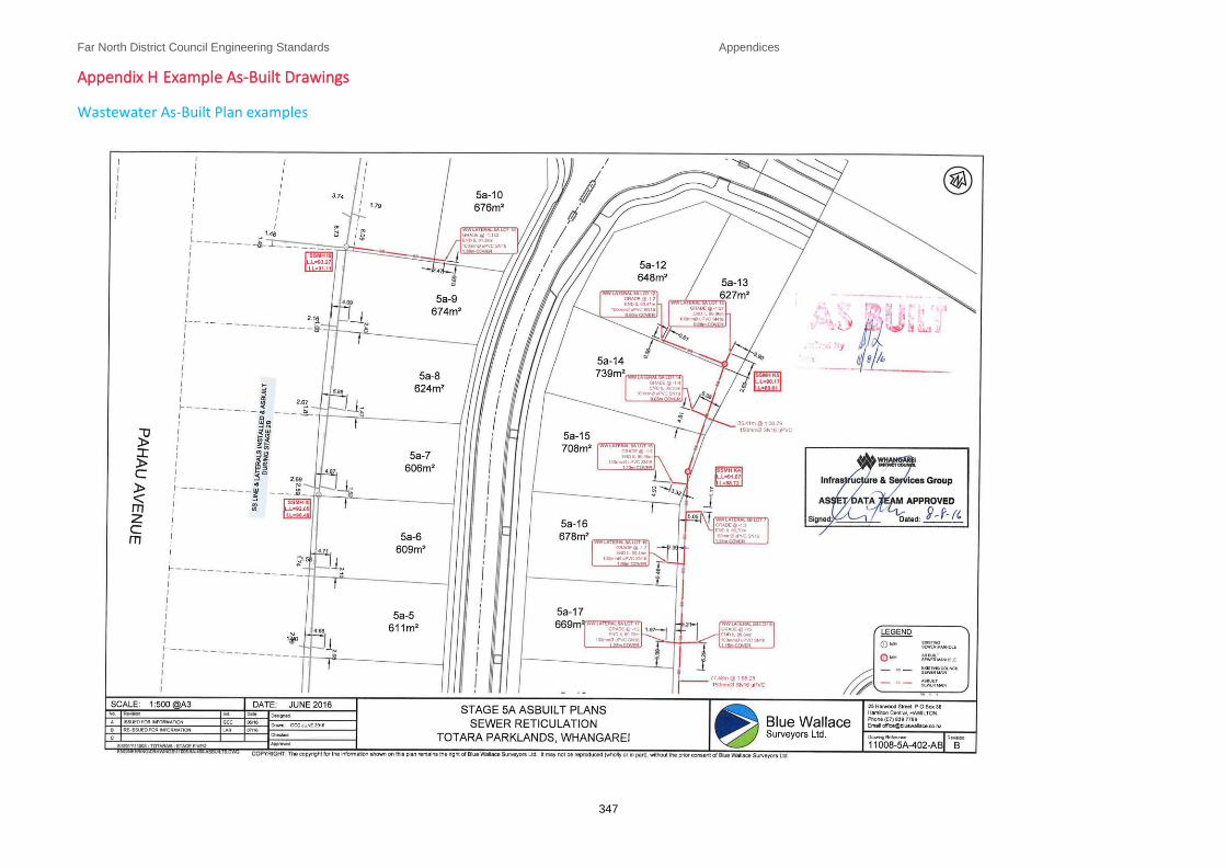
Far North District Council Engineering Standards Appendices
347
Appendix H Example As-Built Drawings
Wastewater As-Built Plan examples
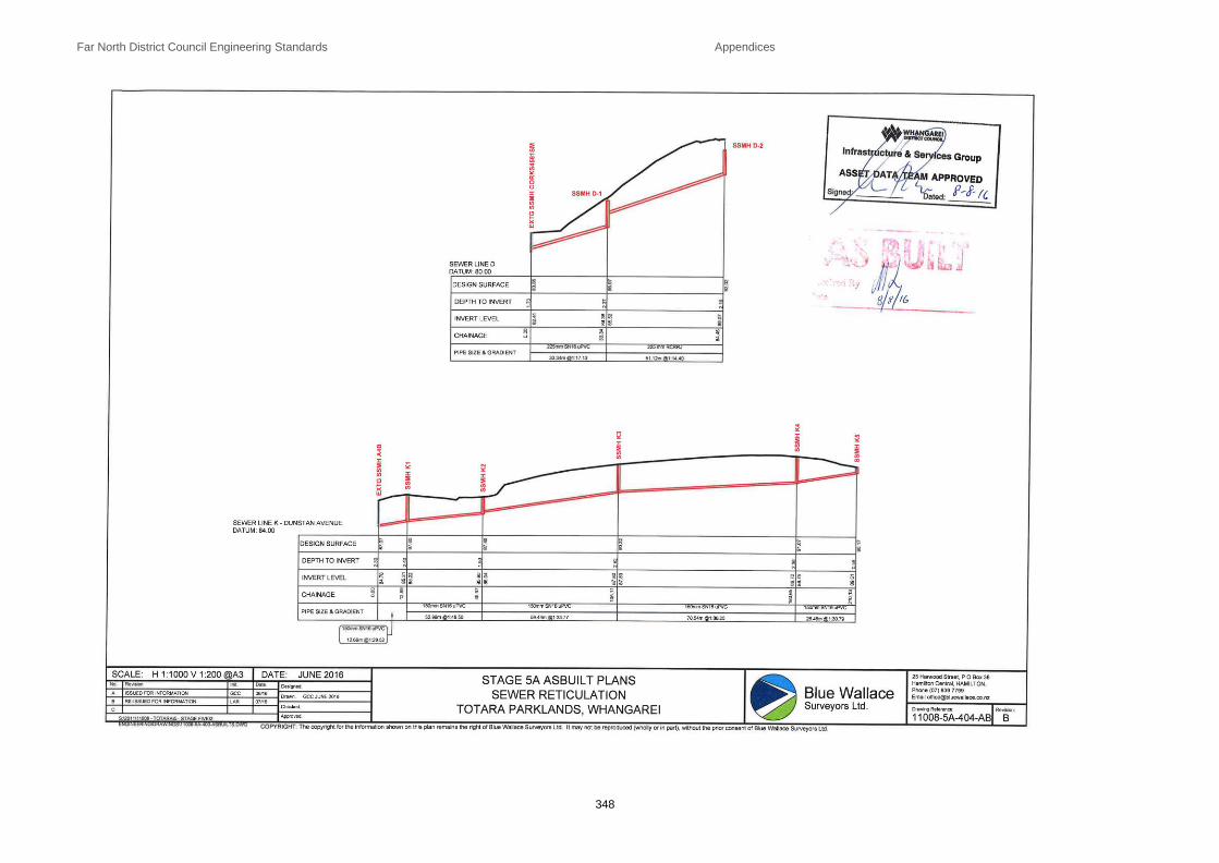
Far North District Council Engineering Standards Appendices
348

Far North District Council Engineering Standards Appendices
349

Far North District Council Engineering Standards Appendices
350
Stormwater As-Built examples

Far North District Council Engineering Standards Appendices
351
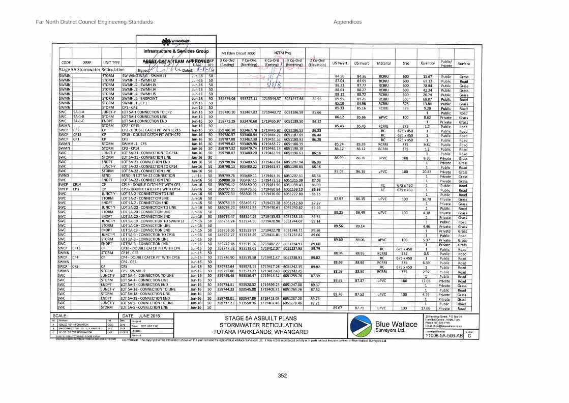
Far North District Council Engineering Standards Appendices
352

Far North District Council Engineering Standards Appendices
353
Water Reticulation As-Built examples

Far North District Council Engineering Standards Appendices
354
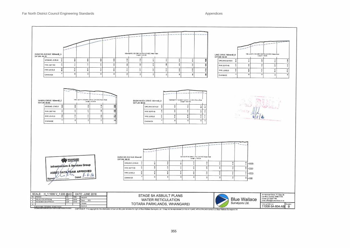
Far North District Council Engineering Standards Appendices
355

Far North District Council Engineering Standards Appendices
356

Far North District Council Engineering Standards Appendices
357
Appendix I Asset Attributes
Roading RAMM
Refer to the FNDC Roading Asset Manager for the Road Assessment and Maintenance (RAMM) Data Collection Sheet.

Far North District Council Engineering Standards Appendices
358
Stormwater
Asset Component Type
Asset Attribute Required Show on plans
Description of Asset Attribute
Stormwater Inlet
Plan ID Yes Plan number used to identify as-built plan
Downstream MH ID Yes
Property ID Yes Either property number or legal description adjacent to manhole
Street Name Yes If street name is not applicable use a property deposited plan (DP) number
Street Type Yes Qualifier to street name e.g. Crescent, Road, Lane, etc.
Location Private property, roadway, berm, reserve
Reduced Level Yes
Structure Type Yes Plain end pipe, headwall, in-ground chamber, etc. Show structure location on plan
Structure Material PVC, concrete, timber, etc.
Eastern Coordinate
Northern Coordinate
Install Date Installation date
Comments Any pertinent comments (particularly water table depth and soil conditions)
Stormwater Pipeline (including culverts)
Plan ID Yes Plan number used to identify as-built plan
Upstream MH ID Yes Use pipe-end ID if pipeline is simply blanked-off
Downstream MH ID Yes Or ID of stormwater outlet structure
Street Name Yes If street name is not applicable use a property deposited plan (DP) number
Street Type Yes Qualifier to street name e.g. Crescent, Road, Lane, etc.
Physical Location Private property, roadway, berm, reserve, adjoining street
Pipe Diameter Yes Nominal bore
Pipe Length Length upstream MH to downstream MH
Pipe Material Yes Material and strength classification
Joint Type RRJ
Invert Level Upstream Yes Pipe invert level

Far North District Council Engineering Standards Appendices
359
Asset Component Type
Asset Attribute Required Show on plans
Description of Asset Attribute
Invert Level Downstream Yes Pipe invert level
Secondary Flow Path Yes Show on As-Built Plans (easement required on private land). Not required on data sheet.
Service Status Yes
Abandoned or removed pipelines are required to be identified on as-built records. Show “A” for abandoned pipes, “R” for removed pipes, otherwise leave blank
Install Date Installation date
Comments Any pertinent comments (particularly water table depth and soil conditions) Identify culverts
Stormwater Connection
Plan ID Yes Plan number used to identify as-built plan
Upstream MH ID Yes Use ‘Pipe-End ID’ if pipeline is simply blanked-off
Downstream MH ID Yes Or ID of downstream asset
Property ID Yes Either property number or legal description
Street Name Yes If street name is not applicable use a property deposited plan (DP) number
Street Type Yes Qualifier to street name e.g. Crescent, Road, Lane, etc.
Service Type Pipe drain, K & C connection
Service Pipe Diameter Yes Nominal bore in millimetres
Service Pipe Length Yes
Service Pipe Material Yes Material and strength classification
Invert Level at Private End Yes Pipe invert level
Depth at Private End Depth from ground level to invert level
Eastern Coordinate Connection
Coordinate of customer end of service connection
Northern Coordinate Connection
Coordinate of customer end of service connection
Distance from left (LB) or right (RB) boundary
Yes Distance to customer connection point relative to left-hand or right-hand boundary facing the property from the street
Distance from front (FB) or back (BB) boundary
Yes

Far North District Council Engineering Standards Appendices
360
Asset Component Type
Asset Attribute Required Show on plans
Description of Asset Attribute
Install Date Installation date
Comments Any pertinent comments (particularly water table depth and soil conditions)
Stormwater Manhole
Plan ID Yes Plan number used to identify as-built plan
MH ID Yes
Property ID Yes Either property number or legal description adjacent to manhole
Street Name Yes If street name is not applicable use a property deposited plan (DP) number
Street Type Yes Qualifier to street name e.g. Crescent, Road, Lane, etc.
Lid Level Yes Top edge and northern part of rim casting
Invert Level Yes
MH Diameter Nominal Bore of MH risers
Eastern Coordinate Location as per lid level
Northern Coordinate Location as per lid level
Service Status Yes
Abandoned or removed pipelines are required to be identified on as-built records. Show “A” for abandoned pipes, “R” for removed pipes, otherwise leave blank
Install Date Installation date
Comments Any pertinent comments (particularly water table depth and soil conditions)
Stormwater Soakage Trench
Plan ID Yes Plan number used to identify as-built plan
Street Name Yes If street name is not applicable use a property deposited plan (DP) number
Street Type Yes Qualifier to street name e.g. Crescent, Road, Lane, etc.
Location Roadway, private, recreation reserve, etc.
Trench Soakage Media Yes
Length Yes
Width Yes
Depth Yes
Ground Level

Far North District Council Engineering Standards Appendices
361
Asset Component Type
Asset Attribute Required Show on plans
Description of Asset Attribute
Invert Level
Eastern Coordinate – End 1
Northern Coordinate - End 1
Eastern Coordinate – End 2 Only one set of coordinates is required if the
Northern Coordinate - End 2 Only one set of coordinates is required if the
Structure Type Yes Proprietary name, lined hole, perforated pipe, etc.
Install Date Installation date
Comments Any pertinent comments (particularly water table depth and soil conditions)
Stormwater Outlet
Plan ID Yes Plan number used to identify as-built plan
Upstream MH ID Yes
Property ID Yes Either property number or legal description adjacent to manhole
Street Name Yes If street name is not applicable use a property deposited plan (DP) number
Street Type Yes Qualifier to street name e.g. Crescent, Road, Lane, etc.
Location Yes Private property, roadway, berm, reserve
Structure Type Yes Plain end pipe, headwall, etc. Show structure location on plan
Structure material PVC, concrete, timber, etc.
Discharges To Name of receiving water body, e.g. Waikato River
Ground Level
Eastern Coordinate Location at point of stormwater discharge
Northern Coordinate Location at point of stormwater discharge
Install Date Installation date
Comments Any pertinent comments (particularly water table depth and soil conditions)
Stormwater Catchpit
Plan ID Yes Plan number used to identify as-built plan
Catchpit ID Yes Provide a catchpit ID to ensure correct association of tabulated information and plan
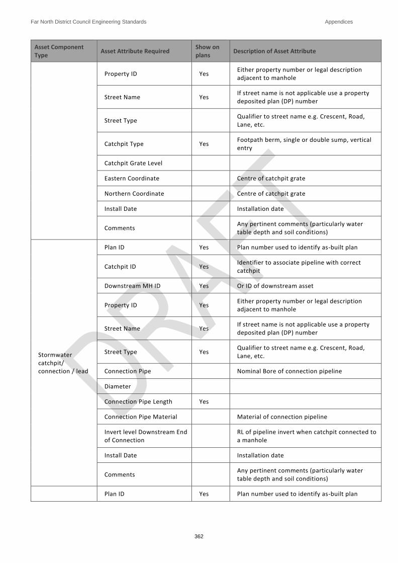
Far North District Council Engineering Standards Appendices
362
Asset Component Type
Asset Attribute Required Show on plans
Description of Asset Attribute
Property ID Yes Either property number or legal description adjacent to manhole
Street Name Yes If street name is not applicable use a property deposited plan (DP) number
Street Type Qualifier to street name e.g. Crescent, Road, Lane, etc.
Catchpit Type Yes Footpath berm, single or double sump, vertical entry
Catchpit Grate Level
Eastern Coordinate Centre of catchpit grate
Northern Coordinate Centre of catchpit grate
Install Date Installation date
Comments Any pertinent comments (particularly water table depth and soil conditions)
Stormwater catchpit/ connection / lead
Plan ID Yes Plan number used to identify as-built plan
Catchpit ID Yes Identifier to associate pipeline with correct catchpit
Downstream MH ID Yes Or ID of downstream asset
Property ID Yes Either property number or legal description adjacent to manhole
Street Name Yes If street name is not applicable use a property deposited plan (DP) number
Street Type Yes Qualifier to street name e.g. Crescent, Road, Lane, etc.
Connection Pipe Nominal Bore of connection pipeline
Diameter
Connection Pipe Length Yes
Connection Pipe Material Material of connection pipeline
Invert level Downstream End of Connection
RL of pipeline invert when catchpit connected to a manhole
Install Date Installation date
Comments Any pertinent comments (particularly water table depth and soil conditions)
Plan ID Yes Plan number used to identify as-built plan

Far North District Council Engineering Standards Appendices
363
Asset Component Type
Asset Attribute Required Show on plans
Description of Asset Attribute
Stormwater Open Channel
Upstream Outlet ID Yes Define lengths of open channel as draining between structures or junctions with other water courses / drains
Downstream Inlet ID Yes Define lengths of open channel as draining between structures or junctions with other water courses / drains
Street Name Yes If street name is not applicable use a property deposited plan (DP) number
Street Type Yes Qualifier to street name e.g. Crescent, Road, Lane, etc.
Location Yes Private property, roadway, berm, reserve, adjoining street
Channel Lining Material Yes
Channel Length Yes Length upstream outlet to downstream inlet
Channel Width Yes
Average Depth Formation depth, ground level to invert level
Invert Level Upstream Yes
Invert Level Downstream Yes
Eastern Coordinate – Upstream Inlet.
Northern Coordinate – Upstream Inlet
Eastern Coordinate – Downstream Outlet
Northern Coordinate – Downstream Outlet
Install Date Installation date
Comments Any pertinent comments (particularly water table depth and soil conditions)
Stormwater subsoil Drain
Plan ID Yes Plan number used to identify as-built plan
Downstream MH ID Yes Or ID of discharge point for drain
Street Name Yes If street name is not applicable use a property deposited plan (DP) number
Street Type Yes Qualifier to street name e.g. Crescent, Road, Lane, etc.

Far North District Council Engineering Standards Appendices
364
Asset Component Type
Asset Attribute Required Show on plans
Description of Asset Attribute
Location Yes Private property, roadway, berm, reserve, adjoining street
Ownership Yes Public or private responsibility for the subsoil drain
Pipe Diameter Yes Nominal bore in millimetres
Pipe Length Yes Length upstream MH to downstream MH
Pipe Material Yes PE, Earthenware, etc.
Invert Level Upstream Yes
Invert Level Downstream Yes
Eastern Coordinate – Upstream End
Northern Coordinate – Upstream End
Eastern Coordinate – Downstream Outlet
Northern Coordinate – Downstream Outlet
Install Date Installation date
Comments Any pertinent comments (particularly water table depth and soil conditions)
Stormwater and detention treatment device
Plan ID Yes Plan number used to identify as-built plan
Street Name Yes If street name is not applicable use a property deposited plan (DP) number
Street Type Yes Qualifier to street name e.g. Crescent, Road, Lane, etc.
Location Private property, roadway, berm, reserve
Site Plan Yes
Site plan showing detention area location and contours relative to adjoining properties and receiving watercourse. To show control structure(s) in both plan and elevation and access provision
Type e.g. Detention area, wet detention pond, wetland, chamber, etc.
Surface Area Yes Surface area at top water level. On the plan, show extent of pond at top water level
Total Capacity Total volume of detention area below top water level

Far North District Council Engineering Standards Appendices
365
Asset Component Type
Asset Attribute Required Show on plans
Description of Asset Attribute
Live Storage Capacity Volume of detention area between normal water level and top water level
Top water level Yes Level at which spillway becomes operative
Outlet invert Yes Invert level of discharge control pipeline (lower operating level)
Install Date Installation date
Comments Any pertinent comments
Secondary Flow Path
Plan ID Yes Plan number used to identify as-built plan
Street Name Yes If street name is not applicable use a property deposited plan (DP) number
Street Type Yes Qualifier to street name e.g. Crescent, Road, Lane etc.
Location Private property, roadway, berm, reserve
Site Plan Yes Site plan showing secondary flow path location and contours relative to adjoining properties and receiving watercourse
Type e.g. grassed swale, concrete footpath
Surface Width Yes Surface width at top water level. On the plan, show extent of secondary flow path at top eater level
Overflow Level Yes RL of point at which overflow into the secondary flow path begins
Comments Any pertinent comments such as covered by easement over xxx property title
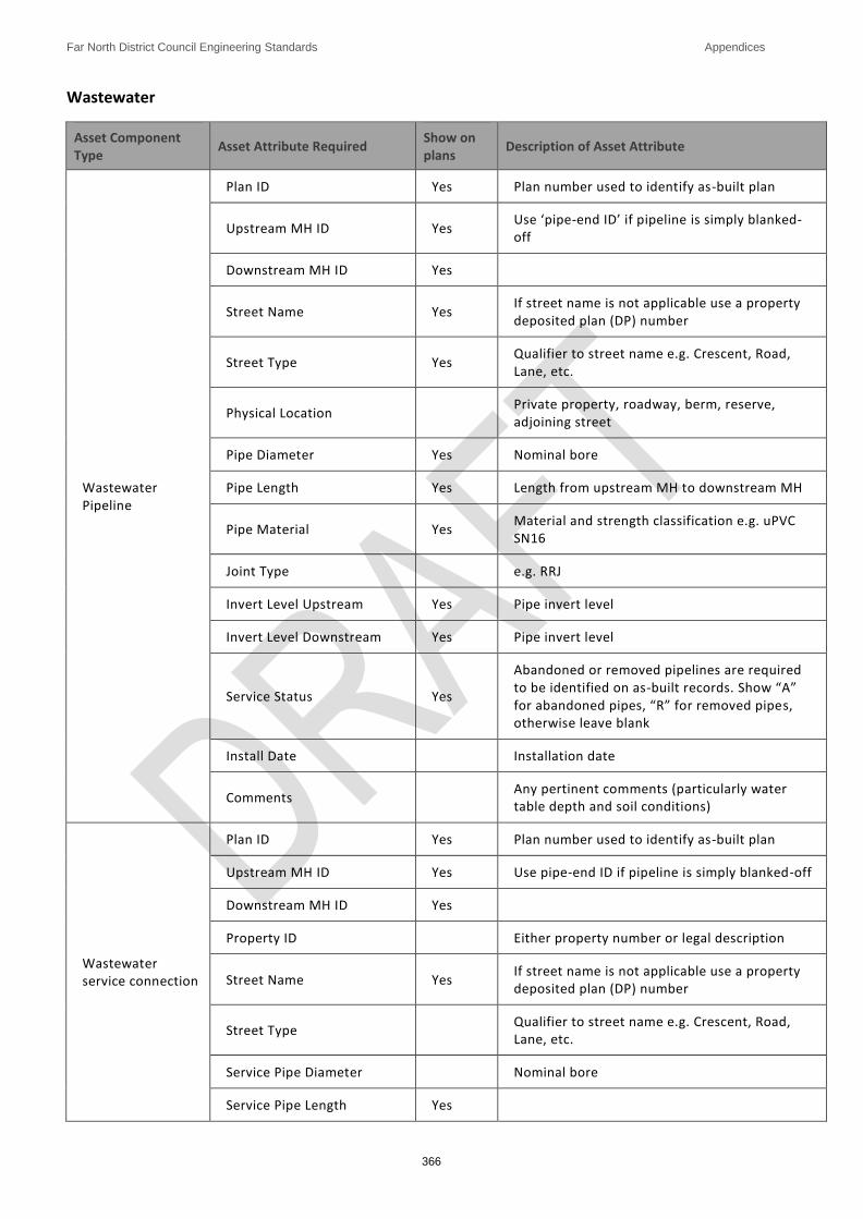
Far North District Council Engineering Standards Appendices
366
Wastewater
Asset Component Type
Asset Attribute Required Show on plans
Description of Asset Attribute
Wastewater Pipeline
Plan ID Yes Plan number used to identify as-built plan
Upstream MH ID Yes Use ‘pipe-end ID’ if pipeline is simply blanked-off
Downstream MH ID Yes
Street Name Yes If street name is not applicable use a property deposited plan (DP) number
Street Type Yes Qualifier to street name e.g. Crescent, Road, Lane, etc.
Physical Location Private property, roadway, berm, reserve, adjoining street
Pipe Diameter Yes Nominal bore
Pipe Length Yes Length from upstream MH to downstream MH
Pipe Material Yes Material and strength classification e.g. uPVC SN16
Joint Type e.g. RRJ
Invert Level Upstream Yes Pipe invert level
Invert Level Downstream Yes Pipe invert level
Service Status Yes
Abandoned or removed pipelines are required to be identified on as-built records. Show “A” for abandoned pipes, “R” for removed pipes, otherwise leave blank
Install Date Installation date
Comments Any pertinent comments (particularly water table depth and soil conditions)
Wastewater service connection
Plan ID Yes Plan number used to identify as-built plan
Upstream MH ID Yes Use pipe-end ID if pipeline is simply blanked-off
Downstream MH ID Yes
Property ID Either property number or legal description
Street Name Yes If street name is not applicable use a property deposited plan (DP) number
Street Type Qualifier to street name e.g. Crescent, Road, Lane, etc.
Service Pipe Diameter Nominal bore
Service Pipe Length Yes

Far North District Council Engineering Standards Appendices
367
Asset Component Type
Asset Attribute Required Show on plans
Description of Asset Attribute
Service Pipe Material Material and strength classification
Invert Level at Private End Yes Pipe invert level
Depth at Private End Depth from ground level to Invert Level
Eastern Coordinate End 1 Coordinate of upstream end of service connection
Northern Coordinate End 1 Coordinate of upstream end of service connection
Distance from left (LB) or right (RB) boundary
Yes Left-hand or right-hand boundary facing the property from the street
Distance from front (FB) or back (BB) boundary
Yes
Install Date Installation date
Comments Any pertinent comments (particularly water table depth and soil conditions)
Wastewater Manhole
Plan ID Yes Plan number used to identify as-built plan
MH ID Yes
Property ID Yes Either property number or legal description adjacent to manhole
Street Name Yes If street name is not applicable use a property deposited plan (DP) number
Street Type Yes Qualifier to street name e.g. Crescent, Road, Lane, etc.
Lid Level Yes Top edge and northern part of rim casting
Invert Level Yes Invert level of wetwell
MH Diameter Nominal Bore of MH risers
Eastern Coordinate Location as per lid level
Northern Coordinate Location as per lid level
Service Status Yes
Abandoned or removed pipelines are required to be identified on as-built records. Show “A” for abandoned pipes, “R” for removed pipes, otherwise leave blank
Install Date Installation date
Comments Any pertinent comments (particularly water table depth and soil conditions)

Far North District Council Engineering Standards Appendices
368
Wastewater Pump Station
Asset Component Type
Asset Attribute Required Show on plans
Description of Asset Attribute
Pump Station General
Plan ID Yes Plan number used to identify as-built plan
Street name Yes If street name is not applicable, use a property deposited plan (DP) number
Street type Yes Qualifier to street name, e.g. Crescent, Road, Lane, etc.
Pump Station Lot Location Yes Show the pump station Lot boundary and surround lots and roads, including the accessway up to the Pump Station
Install Date Installation date
Maximum Design Flow Rates
Design ADWF ADWF – average dry weather flow
Design PWWF PWWF – peak wet weather flow
Pump Station Wet Well
Location Yes Show on a separate pump station site layout plan & cross-section plan at suitable scale
Rising Main Discharge Point Yes Manhole ID
Rising Main Diameter Yes The rising main should appear as an item on the schedule of wastewater pipelines
Overflow Discharges To Yes Refer to the ID of the overflow pipe which should appear as an item on the schedule of wastewater pipelines
Overflow level Yes RL at which overflow begins
Length Yes Internal length dimension of wet well
Width Yes Internal width dimension of wet well
Diameter Yes Internal diameter of wet well (circular wet wells)
Floor Elevation Yes Invert level of chamber
Ground Elevation Yes RL of wet well access covers
Inlet Diameter Yes Repeat for each inlet
Inlet Elevation Yes Repeat for each inlet
Install Date Installation date
Comments Any pertinent comments (particularly water table depth and soil conditions)
Storage Chamber Location Yes Show on a separate pump station site layout plan & cross section plan at suitable scale

Far North District Council Engineering Standards Appendices
369
Asset Component Type
Asset Attribute Required Show on plans
Description of Asset Attribute
Length Yes Internal length dimension of chamber
Width Yes Internal width dimension of chamber
Diameter Yes Internal diameter of chamber (circular chambers)
Floor Elevation Yes Invert level of chamber
Ground Elevation Yes RL of storage chamber access covers
Inlet Diameter Yes Repeat for each inlet
Inlet Elevation Yes Repeat for each inlet
Install Date Installation date
Comments Any pertinent comments (particularly water table depth and soil conditions)
Valve Chamber
Location Yes Show on a separate pump station site layout plan & cross section plan at suitable scale
Water Supply Backflow Prevention Device
Make & Model
Rising Main Check Valve Nominal Bore - Repeat for each valve
Rising Main Isolation Valve Nominal Bore - Repeat for each valve
Install Date Installation date
Comments Any pertinent comments
Odour Control
Location Yes Show on a pump station site layout plan
Length Yes Internal length dimension of chamber
Width Yes Internal width dimension of chamber
Inlet Diameter Yes Repeat for each inlet
Inlet Elevation Yes Repeat for each inlet
Install Date Installation date
Comments Any pertinent comments relating to the type of bio filter media used
Magflow Meter
Location Yes Show on a pump station site layout plan
Manufacturer
Model Number
Magflow Serial number
Install Date Installation date

Far North District Council Engineering Standards Appendices
370
Asset Component Type
Asset Attribute Required Show on plans
Description of Asset Attribute
Pumps each (repeat for each pump)
Manufacturer
Model Number
Performance Curve ID
Motor Serial Number
Motor Current Rating Nameplate current in amps
Motor Power Rating Nameplate power rating in kW
Comments Any pertinent comments (particularly water table depth and soil conditions)
Level Controls
Manufacturer
Model ID
Backup Battery Type
Start Level Repeat for each pump
Stop Level Repeat for each pump
High Alarm Level
Low Alarm Level
Overflow Alarm Level
Comments Any pertinent comments
Electrical Cabinet
Location Yes Show on a pump station site layout plan
Pump Overload Setting Repeat for each pump
Pump Contactor Type Repeat for each pump
Pump Starter Type Repeat for each pump
Install Date Installation date
Comments Any pertinent comments
Telemetry
RT Brand
RT Model
Aerial Type
Micrologix 110 Allen Bradley Module Model
Comments Any pertinent comments (particularly water table depth and soil conditions)

Far North District Council Engineering Standards Appendices
371
Water
Asset Component Type
Asset Attribute Required Show on plans
Description of Asset Attribute
Water pipeline
Plan ID Yes Plan number used to identify as-built plan
Pipe ID Yes
Use a pipe numbering system to link individual pipes and related information such as length, diameter, material, coordinates, etc. Pipe ends occur at pipe intersections and when pipe diameter changes
Pipe Diameter Yes Nominal bore
Pipe Length Yes Show pipeline location on the plan and show dimensions to adjacent boundaries
Laying Depth Yes Average depth below ground level to top of pipe
Pipe Material Yes Material and strength classification
Joint Type RRJ, gibault, welded etc.
Service Status Yes
Abandoned or removed pipelines are required to be identified on as-built records. Show “A” for abandoned pipes, “R” for removed pipes, otherwise leave blank
Install Date Installation Date
Comments Any pertinent comments (particularly water table depth and soil conditions)
Water Connection Service
Plan ID Yes Plan number used to identify as-built plan
Pipe ID Yes Use a pipe numbering system to identify individual pipes if Property ID or Street numbering is not adequate.
Property ID Yes Either property number or legal description
Street Name Yes If street name is not applicable use a property deposited plan (DP) number
Street Type Yes Qualifier to street name e.g. Crescent, Road, Lane, etc.
Service Pipe Diameter Nominal bore
Service Pipe Length Yes Show pipeline location on the plan
Service Pipe Material Material and strength classification
Eastern Coordinate Coordinate of customer end of service pipeline i.e.

Far North District Council Engineering Standards Appendices
372
Asset Component Type
Asset Attribute Required Show on plans
Description of Asset Attribute
at the service valve or toby
Northern Coordinate
Coordinate of customer end of service pipeline i.e.
at the service valve or toby
Toby Lid Level From middle of toby lid
Distance from left (LB) or right (RB) boundary
Yes Distance to customer connection point relative to left-hand or right-hand boundary facing the property from the street
Meter Installed Yes Yes / no response (if yes complete an HCC ‘ Water Meter" form for each installation
Install Date Installation Date
Comments Any pertinent comments
Water Valves
Plan ID Yes Plan number used to identify as-built plan
Pipe ID Yes Use a pipe numbering system to identify individual pipes if Property ID or Street numbering is not adequate
Property ID Yes Either property number or legal description
Street Name Yes If street name is not applicable use a property deposited plan (DP) number
Street Type Yes Qualifier to street name e.g. Crescent, Road, Lane, etc.
Valve Size Nominal bore in millimetres
Valve Manufacturer
Location Yes Roadway, berm
Eastern Coordinate Coordinate of valve
Northern Coordinate Coordinate of valve
Valve Level From middle of Valve Lid
Service Status Yes
Abandoned or removed pipelines are required to be identified on as-built records. Show “A” for abandoned pipes, “R” for removed pipes, otherwise leave blank.
Install Date Installation Date
Comments Any pertinent comments such as ‘attached to anchor block’
Hydrants Plan ID Yes Plan number used to identify as-built plan

Far North District Council Engineering Standards Appendices
373
Asset Component Type
Asset Attribute Required Show on plans
Description of Asset Attribute
Pipe ID Yes Use a pipe numbering system to identify individual pipes if Property ID or Street numbering is not adequate
Property ID Yes Either property number or legal description
Street Name Yes If street name is not applicable use a property deposited plan (DP) number
Street Type Yes Qualifier to street name e.g. Crescent, Road, Lane, etc.
Hydrant Size Nominal bore in millimetres
Hydrant Manufacturer
Location Yes Roadway, berm
Eastern coordinate Coordinate of hydrant
Northern coordinate Coordinate of hydrant
Hydrant Level From middle of Hydrant Lid
Service Status Yes
Abandoned or removed pipelines are required to be identified on as-built records. Show “A” for abandoned pipes, “R” for removed pipes, otherwise leave blank.
Install Date Installation Date
Comments Any pertinent comments

Far North District Council Engineering Standards Appendices
374
Appendix J Checklist for Supporting Information The following checklist is a summary of the requirements of the ES 2018 and should be used as a prompt to the matters which require certification by an IQP:
Geotechnical - Site Suitability and Earthworks (IQP geotechnical)
Note - applicable where cut and fill of the site is proposed
Hazard instability zones
An opinion stated by a geotechnical specialist as to the stability/suitability of the land and should include the
effects from excavation, filling, removal of vegetation, disposal of stormwater & effluent etc.
Hazards - flood hazard exists
Determination of flood extent and level in 1% AEP event (+20%)
What effect it will have on the development and mitigating measures taken to minimise/eliminate effect
What effect the development will have on the flooding (displacement/redirection of flooding etc)
Development within coastal hazard 1 & 2 zones
An assessment of the effect of storm surge, wave run-up etc
Reticulated Sewer
Evidence that the proposed reticulation can service the proposed development and any undeveloped land beyond
Hydraulic design including capacity and self-cleaning velocities
Design of public pump stations and rising mains, including private reticulation, require producer statement
design and construction
Design of private pump stations and rising mains – require producer statement design and construction
Design details of anchor and thrust blocks (including calculations)
Design details of pipe bridges – needs pre-approval of Waste Manager
Design of reticulation larger than 150mm, serving more than 250 lots, pump stations, rising mains, above ground
works, minimum cover not achieved, siphons etc
Specific design and assessment for commercial flows
Specific design for curved pipelines
Steep grades >7% to be graded out
Cleansing velocities achieved. Maximum velocity of 3ms-1 or specific design by IQP
Reticulated Water
Evidence (calculations, existing pressures/supply etc) that the proposed reticulation can service the proposed
development, and any undeveloped land beyond
Evidence that water hammer effects have been considered and appropriate measures included
Required pressures and flows can be met from all hydrants and service connections
Air release/scour valves/pressure reducing valves approved by Water Services
Design details of anchor and thrust blocks (including calculations)
Details of pump stations booster pumps, control valves, proposed ownership written agreements, reservoirs,
make model of pump valves and other equipment – producer statement note
Fire risk classifications and calculations to confirm complying firefighting capacity in terms of SNZ PAS
4509:2008
Details of any above ground reticulation, pipe bridges etc (requires specific design and Water Services approval)

Far North District Council Engineering Standards Appendices
375
Private booster pumps
Stormwater - Private
Evidence that the existing public and/or public reticulation can service the proposed development and any
undeveloped land beyond
Attenuation meets ES requirements. Calculations/model to support attenuation design. Attenuation devices are
serviceable and a producer statement provided including maintenance regime
Details of treatment proposed which complies with the District Plan/EES/NRC-WSP
Assessment of any wetlands included/proposed
Any proposed soakage test in accordance with E2 of the Building Code (Note: no soakage permitted in
medium/high instability areas without Geo-specialist design)
Any soakage proposed is serviceable and silt etc is removed before entering the soakage area
Reticulation adequate for 20% AEP event
Details of open drains/swales, capacities etc
No building over stormwater line or directly alongside without written approval from I & S and specific design
Habitable buildings floor heights set 500mm above 1% AEP flood level
Commercial buildings floor heights set 300mm above 1% AEP flood event
Demonstration of nil effects to surrounding properties as result of development
Stormwater - Public
Extent of overland flowpaths from 1% AEP event
Level of treatment complies
Attenuation meets ES requirements. Calculations/model to support attenuation design
Reticulation adequate for 20% AEP event
Soakage tests in terms of E1 of the building code for any proposed soakage
Any soakage proposed is serviceable. Silt etc is removed before entering soakage area
Flood susceptible areas on hazard maps have been assessed and flood level determined for 1% AEP event
Demonstration of nil effects to surrounding properties as a result of development
Assessment of unstable ground and the effects storm water will have on it, mitigation measures supplied to
enhance stability
Water table drains – calculations to confirm capacity
Velocity/scour control on steep grades on open drains
Cement stabilisation on steep grades
Pipe crossings/bridges
Calculations to show cesspit size is adequate for design volume
Design of treatment devices
Parking and Maneuvering
Plan shows falls and sumps/reticulation/treatment/attenuation calculated to the 1% AEP event
Details of complying parking and manoeuvring
Rights of Way/Accessways
Private bridges require specific design and building consent
Retaining structures require specific design and building consent
Subgrade test confirm CBR >7 (Subgrade >7 requires specific design by IQP)

Far North District Council Engineering Standards Appendices
376
Construction of access will not affect overland flowpaths (up to and including 1% AEP event)

Far North District Council Engineering Standards Appendices
377
Roading - Design
Geotechnical report on stability of ground if road is designed in medium/high instability zone
Subgrade testing shows CBR>7, no specific design – IQP to do testing
Subgrade testing shows CBR<7 – requires specific design
Collector or arterial road requiring specific TOTAL design
Speed limit on road >50km/h requiring specific geometric design
Intersections with collector or arterial road requiring specific design
Roundabout design
Street lighting design
Bridges, culverts, major waterways
Retaining walls
Peer/technical reviews and safety audits
Pavement design depending on CBR, type of road etc
Surfacing design depending on CBR, type of road etc
Surface drainage design
Plan View
Proposed road intersection with existing roads with sight distances
Street lighting details/layout
Details of tapers/turning bays etc
Cross Sections
Stormwater treatment
Existing levels and finished levels shown, cut/fill etc
Steep cuts/fills require CPEng certification
Typical Cross Sections
Pavement design if CBR<7
Subsoil drainage with geotextiles

Far North District Council Engineering Standards Appendices
378
Summary of IQP Certification on Engineering Plans
All Engineering Plans containing proposed works certified by an IQP must contain the IQPs verification for those specific works.
The following schedule of works being certified by the IQP must be attached to the lodgement letter. The schedule must summarise all works being certified by the IQP and reference the relevant plan/sheet number, including multiple works presented on a plan and works where the certification is by more than one IQP.
The IQP must also clearly identify and certify any aspects of the design that are not in accordance with the standard design specified in the ES.
Summary of IQP Certification
Engineering Aspect Detail of works Plan ref IQP
initials
Site Suitability
Earthworks/Compaction design
Land Instability areas
Coastal Hazards, Mine zones,
Flood zones
Road and Access
Roads and Access
Pavement structural design
Geometric design
Surfacing design
Lighting design
Bridges and major culverts
Retaining walls
Stormwater
Catchment Analysis
Overland flow paths (1%AEP)
Stormwater treatment devices
Stormwater attenuation
structures
Wastewater
Gravity reticulation
Sewer pump stations
Rising mains
On-site disposal details
Community wastewater
treatment systems
Pipe bridges & other structure
Water
Water booster stations
Reservoirs
Pipe bridges & other structures

Far North District Council Engineering Standards Appendices
379
Summary of IQP Certification
Engineering Aspect Detail of works Plan ref IQP
initials
Hydraulic design
Other design matters

Far North District Council Engineering Standards Appendices
380
Appendix K List 1. Reserve Playgrounds - Approved Playground Equipment and Surfacing Suppliers and Installers
Play equipment suppliers/installers:
• Playground Centre
• Playco Playgrounds
• Playground People
• Park Supplies and Playgrounds
Playground surfacing suppliers/installers:
• Playmatta
• Playbases
• Numat
• Teamturf
• Playsafe
• Playco
• Play Bark

Far North District Council Engineering Standards Appendices
381
Appendix L List 2. Reserves and Streetscapes - Approved Common Landscape Furniture Products and Suppliers. Note: Approval for products should be sought on a case-by-case basis from Council.
In all instances specific design should be sought to complement local character, the urban design theme and relationship to other chosen products.
1. Benches:
Criteria for appropriate reserve and streetscape seating are:
• Comfortable, accessible (i.e. ideally with a back and arm rest/s), easy to maintain (not-painted), durable, either hardwood timber, recycled composite or sufficiently treated, flush surface mounted with stainless steel fixtures to concrete pad with sufficient room for maneuvering, continuous pathway hard surface access, placed in a way for meet good CPTED principles.
• Reserve seating should be focused around pedestrian networks at regular intervals, near children’s playgrounds for caregiver supervision, and where people naturally congregate for views or to wait.
Below are some examples of appropriate products:
o Streetscape - Metro or Rendezvous Seat.
o Urban Effects - Citi-style Seat.
o Metal Art - Civic Seat.
2. Picnic Sets:
Criteria for appropriate reserve picnic tables:
• Comfortable, accessible (i.e. with ability for those in wheelchairs and mobility scooters to also be seated at the table) easy to maintain (not-painted), durable, either hardwood timber, or sufficiently treated, recycled composite, or concrete flush surface mounted with stainless steel fixtures to concrete pad with sufficient room for maneuvering (i.e. 1.3m min surfacing around the full table), continuous pathway hard surface access, with some option for shade/protection, placed in a way for meet good CPTED principles.
• Picnic seating should be focused around where people meet to eat – in civic parks next to take-away outlets, in parks that provide barbeque facilities or other areas where people meet to picnic.
Below are some examples of appropriate products:
o BUSK Concrete Picnic Table– plain or coloured and sealed.
o Streetscape - Metro or Rendezvous Picnic Set.
o Urban Effects - Citi-style Bench.
o Metal Art - Avalon Picnic Set.
3. Shade Structures:
Criteria for appropriate shade structures:
• Attractive, robust, wind/storm and UV resistant (note structures over 50m2 require consent), vandal/climb resistant, efficient in shading and providing basic shower protection.
Below are some examples of appropriate products:
o Shade Systems - Star Shade Structure.

Far North District Council Engineering Standards Appendices
382
o Sunshade.
4. Bollards, Barriers and Rocks:
Criteria for appropriate bollards, barriers and rocks:
• Bollard material can range from timber, recycled plastic/timber composite, stainless steel, galvanised steel, epoxy-painted or powder coated plain steel, or sealed (corten) mild steel. Timber must be H4 treated or equivalent hardwood. Appropriate dimensions are min 100mm square (can be up to 300mm square). To be at height of minimum 600mm, 900mm (ideal)– 1200mm max out of ground. Removable bollards with steel hinge joint or steel sleeve to be used for vehicle access areas. All bollards to have concrete mowing strip of min 100mm clearance around base. Ideally a contiguous mowing strip for bollards in a row to reduce maintenance. Timber bollards are ideally plain or stained timber but not painted. Rebating for local decorative effect can be incorporated as appropriate.
• One – Three Rail fence (see Drawing Sheet ** for details)
• Rocks must be a minimum 800cm round with a flattish top (so people can sit on them), ground mounted with concrete surround for ease of grass maintenance. 300mm clearance is recommended. Local sourced rocks are considered most appropriate.
Below are some examples of appropriate products:
o Streetscape - Cutlass Bollard.
o Urban Effects – Word Corten Bollard.
5. Waste Bins and Recycling Receptacles:
Criteria for appropriate waste bins and recycling receptacles:
• Council currently utilises a number of different types of bins in reserves and streetscapes including St Louis bins, Ly’s bins, Colonial Tilt bins, Wheelie-bin enclosures, TOM litter bins and a number of others. It is recommended new bins match or compliment the surrounding landscaping as best as possible.
• Bins should range between 60litre to –240litre capacity depending on placement, how often they are serviced, and local character
• Bins should be rationalised to encourage disposal of waste created only when using the reserve or streetscape (i.e. picnic or takeaway waste etc.) rather than household or other waste. A pack-in, pack-out philosophy is adopted for other areas.
• All bins should be mounted on hard surfacing/concrete for ease of maintenance and servicing and in close proximity to main paths, picnic seats or amenity areas.
• Bins should be easy to service and clean, discourage interference from birds and other animals.
• Recycling options should be added next to refuse bins in key waste collection areas and clearly labelled as such to avoid contamination.
Below are some examples of appropriate products:
o Tilley Group – Recycling Bins.
o Metal Art – Wheelie-Bin Enclosures.
6. Bikes and Scooter Racks:
Criteria for appropriate waste bins and recycling receptacles:

Far North District Council Engineering Standards Appendices
383
• Bike racks can be made with a range of robust materials (as per bollards) and mounted as such to avoid trip/obstruction hazards and vandalism.
• Racks are best located as part of stopping points along the cycle network, at various convenient points in urban centres (such as near libraries and other service centres) at bigger playgrounds and near toilet facilities. Scooter racks should be considered for inclusion near skate facilities or pump parks.
Below are some examples of appropriate products:
o Urban Effects – Bike and Scooter Rack range.
o Tilley Group – Ruru Bike Stand and Spiral Hoop.
7. Drinking Fountains and other Water Dispensers:
Criteria for appropriate drinking fountains, and other water dispensers:
• Drinking fountains and other water dispensing features must be sited on proper concrete (or clean free-draining hardstand) and have good drainage - ideally a dedicated sump/drain that takes the used water way from the area.
• Drinking fountains dispensing clean potable water are best situated near children's playgrounds, at particular rest points along trails or other key urban areas and connected to a hard-surfaced path network. Consideration should also be given to accessibility to those who use mobility devices such as wheelchairs.
• Outdoor shower towers may be installed in particular circumstances in areas where people wash (sand, salt etc.) off after swimming or changing.
• Care must be in choosing items that have automatic off valves and are low flow therefore not wasting water unnecessarily. Dedicated nearby rainwater off buildings may be utilised for capture to supplement supplies as long as supply is safe and potable.
• Stainless steel fixtures should be used for ease of cleaning and for rust prevention.
Below are some examples of appropriate products:
o Mountain Fresh – Freestanding Fountain (powder-coated)
o Filters and Fountains – Stainless Steel Drinking Fountain, Wheelchair Accessible Drinking Fountain and Shower Tower.
o Urban Effects – Hydrate Fountain.
8. Public Barbecues:
Criteria for appropriate public barbeques:
• Public barbeques require significant servicing and maintenance – so inclusion of these facilities should only be considered for premier playground parks with picnic tables where there are no takeaway facilities nearby and where there are nearby bins for food waste.
• Single plate facilities with bench space for preparation are recommended.
• Barbeques should be installed under a roof structure to prevent rain filling up fat drip trays and overflowing causing a health hazard.
• Barbeques should also be installed on a sufficient sized concrete pad, with fully connected hard surface pathways for accessibility – including for users in wheelchairs and other mobility devices.

Far North District Council Engineering Standards Appendices
384
• Automated, electric, push-button facilities are recommended – so that they can't be left on risking accidental burns, fires lit in them or otherwise easily vandalised.
Below are some examples of appropriate products:
o Urban Effects – Urban Electric Easy Access Single Barbeque.
o Greenplate – Electric and Solar Barbeques.
9. Fences and Gates.
Criteria for appropriate reserve fencing and gates:
• Although a specific company (such as Boundaryline or Hamden) is not required to be engaged – the same quality standards and general specifications are to utilised for reserve fencing and gate construction.
• Urban fencing in premier parks and reserves should in most instances have contiguous concrete mowing strips underneath for ease of regular mowing/vegetation maintenance.
Below are some examples of specifications to be followed:
o Boundaryline – Sentry Flat Top Fence (permeable, powder-coated, low steel fence)
o Boundaryline – Durapanel Delta Aluminium Gates (as above for entrances)
o Boundaryline - Sentry Panel School Panel Fence (as above but taller)
o Boundaryline – Durapanel Titan Safety Fence (as above for on top of retaining walls)
o Boundaryline – Colourpanel Flattop Fence (taller partly permeable option – may be appropriate around residential areas, requiring some privacy)
o Boundaryline – Kiwipanel Fence (around courts/sports areas where needed – galvanised)
o Boundaryline – Post and Rail Fences (plain or painted H4 timber)
o Hamden – Manual Swing Barrier Arms (parks, sports grounds, carparks restricted vehicle entry)
10. Vehicle Wheel-stops:
Criteria for appropriate vehicle wheel-stops:
• Vehicle wheel-stops should be included in all public car parking bays fronting or angling on to public reserve paths to prevent the fronts of vehicles from encroaching over the available pathway/s or damaging boundary fencing.
• Wheel-stops must be fit for purpose, durable and properly installed. Ideally these should comply with AS/NZS2890. 1-2004.
• These should ideally be striped or reflectorised in parking areas that are to be used after dusk.
• The parking configuration and installation of wheel-stops must not compromise access to pedestrian paths. I.e. – a minimum of 1.3 meters gap must be provided to all paths to allow for accessibility.
• Care should be taken in choosing products that don't cause damage the bumpers of cars.
Below is an example of an appropriate product:
o Blackwoods – Rubber Wheel-stop.
11. Tree Surrounds and Tree Grates:

Far North District Council Engineering Standards Appendices
385
Criteria for appropriate tree surround and tree grates:
• In most circumstances it is better to plant the recommended specification trees with no tree surround than to use tree surrounds – i.e. trees to be 2m minimum in height, free trunking, with trunk diameter at 1m of 60-80mm with proper staking. Vandals can sometimes use the surround to lever and snap a new tree.
• If tree surrounds are to be used, then they are best used in streetscape CBD areas where there is adequate passive surveillance.
• Tree grates should be used in areas with significant surrounding hard surfacing as part of WSD (water sensitive design) systems to reduce stormwater run-off, to protect tree roots from being trampled and to ensure the tree has access to adequate rainfall.
Below are some examples of appropriate products:
o Streetscape – Tree Surrounds
o Streetscape – Tree Grates
o Permapave or Firth – Permeable paving (alternative to tree grate)
12. Boardwalk, Sand-ladder and Jetty Planking:
Criteria for appropriate boardwalk, sand-ladder and jetty planking:
• Durability and ongoing maintenance of materials for site is a major consideration for choice of product for boardwalks, sand-ladders and jetty planking.
• Traction and general user safety are also key considerations. Shaded and perpetually damp areas may require further traction coatings/treatment.
• Timber/plastic composite or recycled plastic products should be considered as alternative to timber in coastal settings – as these can be more durable and may be a more environmentally sustainable option than hardwoods.
Below is an example of an appropriate product:
o Metal Art or Replas – Enduroplank and Enduromesh
13. Tree Planters:
Criteria for appropriate tree planters:
• Generally, it is better to plant street trees in ground where at all possible where trees can access available ground water and nutrients and roots can grow freely.
• In areas where trees cannot be planted inground then specific design is required for above ground tree planter/containers including durable construction material and sealants, and appropriate dimensions/size for the root systems of the chosen species to ensure the ongoing health of the tree.
• Other considerations are installation of artificial irrigation systems, traffic safety if used within or in close proximity to the road corridor, and the ability to uplift and shift planters and transplant trees as required.
• Top quality planting medium is required for use in all tree planters.
• Treated timber alone is not an appropriate material for the construction of planters.
Below are some examples of appropriate products:
o Metal Art – Streetscape Planters
o Urban Effects – Toi Toi, Dahlia, Timber or Onice Planter

Far North District Council Engineering Standards Appendices
386
14. Play Equipment and Play Surfacing:
Note: Most detail regarding design of reserve play equipment and play surfacing is covered off in the Chapter. Council currently has several old or community-made play facilities throughout the district that do not meet current standards. These older facilities are required to be upgraded to the current NZ Standards for Playgrounds and Playground Surfacing when these are renewed or upgraded.
Criteria for selection of play equipment and play surfacing:
• Play products and professional installation that meets the current NZ Standards for Playgrounds and Playground Surfacing is required for all new play equipment and play surfacing installation.
• Consideration should be given to using professional companies that Council has engaged previously in other playgrounds across the district for ease of maintenance and parts supply. Some suppliers also do a good range of more ‘natural’ play items and design.
• Access to play equipment for children and caregivers with disabilities must be factored. A mix of universally accessible equipment and accessible surfacing must be considered for all new playgrounds and significant upgrades. (i.e. contiguous hard-surface pathways connecting to entrances flush to ground level with concrete edging and solid rubber surfacing, as well as some inclusive play equipment - meaning people of different physical abilities, ages and stages can play on them.)
Below are some examples of appropriate designers, suppliers and installers of public playgrounds - play equipment and play surfacing products:
o Playground Centre
o Playground People
o Playco Playgrounds
o Playmatta and Playbases
o Numat
15. Dog Agility/Dog Exercise Parks:
Criteria for selection of dog agility equipment for use in dog exercise parks and areas:
• Dog on and off-leash exercise areas currently exist in a number of parks and reserves across the district but to date there are no dedicated enclosed dog exercise parks or agility areas.
• Dedicated dog exercise/agility areas should ideally be fully fenced with facilities for both dogs and humans – i.e. dog bags and bins, hard-surfacing, seating, shade, water etc.
• Predesigned and tested dog agility equipment that isn’t made of timber should be considered as these are easier to clean and often more durable.
• Any equipment chosen should be installed with consideration of the differing abilities of dog owners and ease of surrounding park maintenance.
Below is an example of an appropriate product:
o Metal Art – Dog Agility Tracks
16. Reserve Signage:
Criteria for signage:
Note: Signage within the road corridor must comply with the Transportation Chapter and any applicable bylaw.

Far North District Council Engineering Standards Appendices
387
• Council maintains a standard design portfolio for park and reserve signage (sizes/dimensions, fonts, layout, colours, spacing and symbols/maps etc.) that must be utilised for general park names, labelling key facilities, wayfinding and other standard signage – such as bylaw information etc.
• Council owns and maintains or must approve any signage by others prior to installation to be installed on Council managed land.
• Interpretation and other placemaking signage can and should be used where they add value. These signs allow for some additional design and creativity. These signs may contain cultural, historical, and/or ecological information. They should be unique to the place, and part of an identifiable family of signs.
• General principles for all signs are:
o Signs need to be securely installed and should have concrete underneath for ease of maintenance.
o Signs should be bright and easily read by people with diminished eyesight.
o Wayfinding signs should be kept to a minimum – use landscaping (paths etc.) instead.
o Signs should be easy to read, have a solid standing area underneath (where they are to be read from) be durable, colourfast, and have graffiti guard to reduce damage by vandalism.
o Any content will need to be vetted with appropriate parties and their inclusion needs to be approved by Council.
• Consideration is currently being given to adoption of some signage rationalisation initiatives - including access to on-line links (via QR or website links) for detailed information that is not critical for standard signs.
• Bilingual signage – in Te Reo and English should also be considered for inclusion.
17. Sculptural Installations:
Note: Landscape furniture is often an aesthetic three-dimensional ‘artwork’ in its own right. It is a positive to consider both the aesthetic and functional aspects when choosing all landscape furniture.
Criteria for sculptural installations:
• Sculptural installations can be incorporated in to reserves and streetscapes as part of good placemaking. They should be unique to the place and be meaningful in some way.
• Sculptural installations within streetscapes must also consider aspects such as frangibility (if collided with), clear sightlines, wind loading, reflectivity and other such considerations.
• Sculptures in reserves offer more flexibility in size, materials and placement, however they must be durable, vandal-proof and reasonably easy to maintain.
• Sculptures should ideally be connected to a regularly used pathway network and be a prominent focal point as part of reserve design. They shouldn't obstruct movement or cause undue health and safety issues – such as trip hazards, sharp corners etc.
• Local design and manufacture should be encouraged for meaningful placemaking.
• All sculptures must be approved by Council prior to manufacture and/or installation. Dependent on the structure, professional engineering and consents may also be required.
Below are examples of off the shelf sculptural installations:
o Metal Art – Art Installations – Smiling Windmill and Urban Forest Cubes
18. Wall Murals and Ground Surface Artworks.
Criteria for wall murals and ground surface artworks:

Far North District Council Engineering Standards Appendices
388
• Like sculptural installations wall murals and ground surface artwork should ideally be designed locally and reflect local character, people and place. Artworks can add significantly to local placemaking and assist in vandalism resistance.
• Ideal placement for wall murals are on large plain walls in main civic areas that are public facing (both Council - and if approved - by the owner of private walls), on the exterior of toilets or other plain public buildings near playgrounds.
• Ground surface artworks may be on reserve paths or other hard-surfacing surfacing – and could be for example designs soda-blasted in concrete, tactile vinyl coverings or other approved painted surfacing. Care and consideration must be given to aspects such as durability, UV resilience, reflectivity and traction.
• Ground surface artworks may also be part of the road corridor – at road crossings or as part of traffic calming interventions. Special considerations are required to meet criteria contained in more detail in the Transportation chapter.
• All works should be properly crafted, applied and if applicable graffiti-guarded to prevent premature wear and vandalism.
• All murals and ground surface artworks must be approved by Council prior to manufacture and/or installation. There should be an understanding that the mural may not last forever and may get replaced or repainted over in years to come.
Below are examples of various wall murals and ground surface applications:
o Hundertwasser artworks – Mosaic, Painted etc.
o Polymer Group – Nelson Street Cycleway (Auckland) - Enduragrip PU High Performance Coloured High Friction Surfacing Treatment.
o Sodablast – Concrete Etching (Rotorua) – Share with Care on Shared Paths

Far North District Council Engineering Standards Appendices
389
Appendix M List 3. Reserves and Streetscapes - Suitable Shrub and Plant Species for Reserve and Streetscape Planting
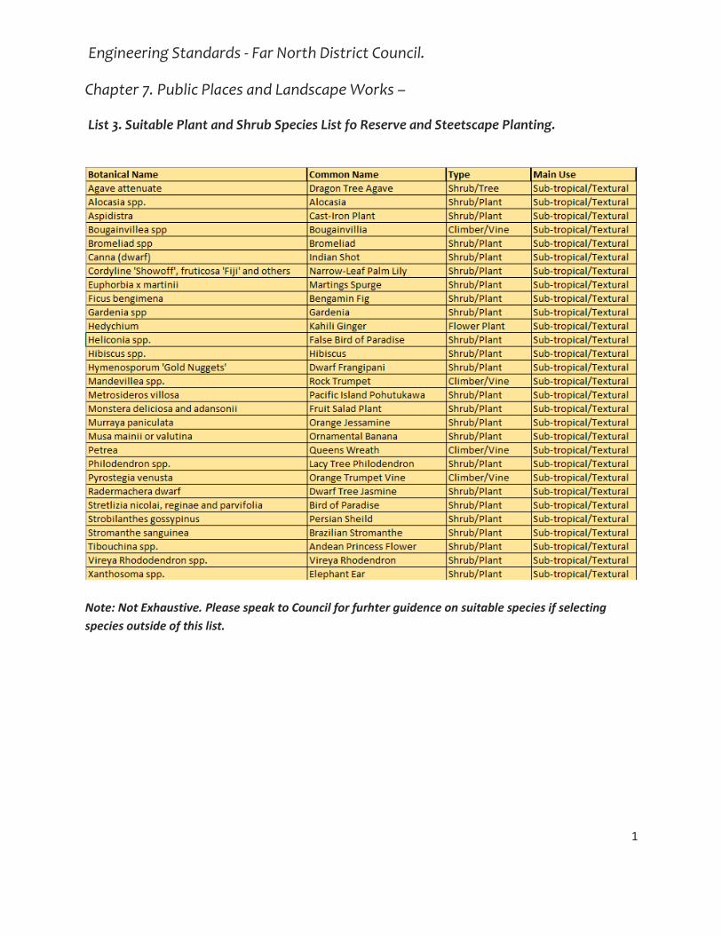
Engineering Standards - Far North District Council.
Chapter 7. Public Places and Landscape Works –
List 3. Suitable Plant and Shrub Species List fo Reserve and Steetscape Planting.
1
Note: Not Exhaustive. Please speak to Council for furhter guidence on suitable species if selecting
species outside of this list.

Engineering Standards - Far North District Council.
Chapter 7. Public Places and Landscape Works –
List 3. Suitable Plant and Shrub Species List fo Reserve and Steetscape Planting.
2
Note: Not Exhaustive. Please speak to Council for furhter guidence on suitable species if selecting
species outside of this list.
See: A Planters Handbook for Northland Natives - including special plants for wetlands, coast and
birdfood for more specific ecological planting information.

Engineering Standards - Far North District Council.
Chapter 7. Public Places and Landscape Works –
List 3. Suitable Plant and Shrub Species List fo Reserve and Steetscape Planting.
3

Far North District Council Engineering Standards Appendices
390
Appendix N List 4. Reserves and Streetscapes - Suitable Tree Species for Reserve and Streetscape Planting.

Engineering Standards - Far North District Council.
Chapter 7. Public Places and Landscape Works –
List 4. Specimen Tree List – Street and Reserve Tree Species
Botanical Name Common Name Type Main Use
Amelanchier canadensis Shad Bush Deciduous Street/Park
Carpinus betulus 'Fastigata' Upright Hornbeam Deciduous Street
Fagus sylvatica 'Dawyck Green' Upright Green Beech Deciduous Street
Fraxinus pennsylvanica 'Cimmzam'
Cimmaron Ash Deciduous Street
Fraxinus 'Purple Spire' Purple Spire Ash Deciduous Street
Lagerstroemia indica 'Kimono' Crepe Myrtle Deciduous Street
Lagerstroemia indica 'Saint Emilion'
Crepe Myrtle Deciduous Street
Magnolia 'Heaven Scent' Gresham Hybrid Magnolia
Deciduous Street
Magnolia 'Milky Way' Magnolia Jury Hybrid Deciduous Street/Feature
Magnolia 'Star Wars' Magnolia ‘Star Wars’ Deciduous Street
Pyrus cal. Aristocrat Ornamental Pear Deciduous Street/Feature
Pyrus cal. 'Candelabra' Birch Leaf Pear Deciduous Street/Feature
Pyrus cal. 'Kea' Ornamental Pear Deciduous Street/Feature
Botanical Name Common Name Type Main Use
Alectryon excelsus Titoki Evergreen Street/Native
Fraxinus griffithii Evergreen Ash Evergreen Street
Hymenosporum flavum Australian Frangipani Evergreen Street
Magnolia 'Main Street' Evergreen Magnolia Evergreen Street
Metrosideros 'Māori Princess' Pohutukawa single stem Evergreen Street/Native
Michelia doltsopla 'Silver Cloud' White Michelia Evergreen Street/Feature
Michelia maudiae South China Michelia Evergreen Street/Feature
Nestegis ‘Montana’ Mountain Maire Evergreen Street/Native
Nestegis apetala Coastal Maire Evergreen Native/Street
Olea europea 'Luccino' Ornamental Olive Evergreen Street/Park
Rhopalostylis sapida Nikau Evergreen Street/Native
Sophora fulvida Kowhai (northern) Evergreen Street/Native
Tristaniopsis laurina Water Gum Evergreen Street/Park
Note: Specific selection of street tree species must be prior approved dependant on environmental situation and project .
List is also not exhaustive. Please speak to Council for further assistance if recommending species not on this list.

Engineering Standards - Far North District Council.
Chapter 7. Public Places and Landscape Works –
List 4. Specimen Tree List – Street and Reserve Tree Species
Botanical Name Common Name Type Main Use
Acer freemanii Freemans Maple Deciduous Park
Acer griseum Paperbark Maple Deciduous Park/Feature
Acer palmatum 'Bloodgood' Japanese Maple Deciduous Park/Feature
Acer platinoidies 'Nigrum' Norway Maple Deciduous Park
Acer rubrum Red Maple Deciduous Park/Feature
Acer saccharum Sugar Maple Deciduous Park/Feature
Aesculus carnea Pink Horse Chestnut Deciduous Park
Alibizzia julibrissin ‘Red Silk’ Red Persian Silk Tree Deciduous Park
Alnus imperialis Cut Leaf Alder Deciduous Park
Alnus rubra Red Alder Deciduous Park
Betula utilis 'jacquemontii' Himalayan Birch Deciduous Park
Cercidiphyllum japonicum Katsura Deciduous Park
Cercis canadensis Eastern Redbud Deciduous Park
Cornus nutalli Pacific Dogwood Deciduous Park
Davidia involucrata Dove Tree Deciduous Park/Feature
Eycryphia cordifolia Spanish Elm Deciduous Park
Fagus sylvatica Copper Beech Deciduous Park
Fraxinus augustifolia 'Raywoodii'
Claret Ash Deciduous Park/Feature
Fraxinus excelsior English Ash Deciduous Park
Fraxinus velutina Arizona Ash Deciduous Park
Gingko biloba Gingko (male only) Deciduous Park/Feature
Gleditsia tricanthos Honey locust Deciduous Park
Jacaranda mimosaefolia Jacaranda Deciduous Park
Liriodendron tulipfera fastigiatum
Tulip Tree Deciduous Park/Feature
Nyssa sylvatica Tupelo Black Gum Deciduous Park/Feature
Parottia persica Persian Ironwood Deciduous Park/Feature
Pistacia chinensis Chinese Pistachio Deciduous Park/Feature
Prunus spp. Fruiting Plum Deciduous Street/Park
Pyrus cal. 'Bradford' and others Ornamental Pear Deciduous Park
Pyrus salicifolia Willow Leaf Pear Deciduous Park
Pyrus spp. Fruiting Pear Deciduous Park/Fruiting
Quercus coccinea Scarlet Oak Deciduous Park/Feature
Quercus palustris Pin Oak Deciduous Park
Sorbus aria 'Lutescens' Silver Whitebeam Deciduous Park
Stewartia pseudocamellia Japanese Stewartia Deciduous Park
Styrax japonca Japanese Snowbell Tree
Deciduous Park/Feature
Ulmus glabra horozontalis Spreading Elm Deciduous Park/Feature
Ulmus hollandica Upright Elm Deciduous Park/Feature
Zelkova cerrata Japanese Zelkova Deciduous Park/Feature

Engineering Standards - Far North District Council.
Chapter 7. Public Places and Landscape Works –
List 4. Specimen Tree List – Street and Reserve Tree Species
Botanical Name Common Name Type Main Use
Agathis australis Kauri Evergreen Park/Native
Albertia magna Natal Flame Tree Evergreen Park/Feature
Alnus jourullensis Evergreen Mexican Alder
Evergreen Park
Aloe banseii Tree Aloe Evergreen Park/Feature
Backhousia citriodora Lemon Myrtle Evergreen Park
Beilschmiedia tarairi Tairere Evergreen Park/Native
Belischmiedia tawa Tawa Evergreen Park/Native
Brachychiton acerifolia Flame Tree Evergreen Park/Feature
Calodendrum capense Cape Chestnut Evergreen Park/Feature
Ceratopetalum gummiferum NSW Christmas Bush Evergreen Park
Citrus spp. Orange/Lemons Evergreen Park/Fruiting
Corynocarpus laevigatus Karaka Evergreen Park/Native
Dacrycarpus dacrydioidies Kahikatea Evergreen Park/Native
Dacrydium cupressinum Rimu Evergreen Park/Native
Dysoxlyum spectabile Kohekohe Evergreen Park/Native
Elaeocarpus dentatus Hinau Evergreen Park/Native
Eucalyptus leucoxylon rosea Red Gum Evergreen Park/Feature
Gordonia axillaris Fried Egg Tree Evergreen Park/Feature
Hedycarya arborea Pigeonwood Evergreen Park/Native
Knightia excelsa Rewarewa Evergreen Park/Native
Laurelia novae-zelandiae Pukatea Evergreen Park/Native
Librocedrus plumosa Kawaka Evergreen Park/Native
Meryta sinclairii Puka Evergreen Park/Native
Metrosideros bartlettii Bartletts Rata Evergreen Park/Native
Metrosideros 'Scarlet Pimpernel'
Pohutukawa hybrid Evergreen Park/Native
Myrsine salicina Toro Evergreen Park/Native
Nestegis cuninghamii Black Maire Evergreen Park/Native
Nestegis lanceolata White Maire Evergreen Park/Native
Olea 'El Greco' Fuiting Olive Evergreen Park/Fruiting
Phyllocladus trichomandiodes Tanekaha Evergreen Park/Native
Planchonella costata Tawapou Evergreen Park/Native
Planchonella costata Tawapou Evergreen Park/Native
Podocarpus henkelii Henkel's Yellowwood Evergreen Park/Native
Podocarpus totara Totara Evergreen Park/Native
Podocarpus totrara 'aurea' Golden Totara Evergreen Park/Native
Prumnopitys ferruginea Miro Evergreen Park/Native
Prumnopitys taxifolia Matai Evergreen Park/Native

Engineering Standards - Far North District Council.
Chapter 7. Public Places and Landscape Works –
List 4. Specimen Tree List – Street and Reserve Tree Species
Sophora microphylla 'fulvida' Kowhai Evergreen Park/Native
Stenocarpus sinuatus Fire-wheel Tree Evergreen Park/Feature
Syagrus romanzoffiana Queen Palm Evergreen Park/Feature
Sygyzium maire Swamp Maire Evergreen Park/Native
Tilia cordata 'Spring Glow' Linden Lime Tree Evergreen Park/Feature
Vitex lucens Puriri Evergreen Park/Native
Weinmannia silvicola Towai Evergreen Park/Native
Note: Specific selection of reserve/park/feature tree species must be prior approved dependant on environmental situation and project .
List is also not exhaustive. Please speak to Council for further assistance if recommending
species not on this list.

Far North District Council Engineering Standards Appendices
391
Appendix O Spreadsheet 1. Public Toilets – Gold and Silver Standards for New Public Conveniences

Far North District Council Engineering Standards Drawing Sheets
392
Drawing Sheets

Far North District Council Engineering Standards Drawing Sheets
393
SHEET 1 STANDARD SYMBOLS ........................................................................................................... 396
SHEET 2 URBAN ROAD AND SERVICE LANE DETAILS ......................................................................... 397
SHEET 3 RURAL ROAD DETAILS .......................................................................................................... 398
SHEET 4 TRAFFIC SIGHTLINES FOR VEHICLES ENTRANCES ................................................................. 399
SHEET 5 SCALA PENETROMETER CHART ............................................................................................ 400
SHEET 5A EQUIVALENT SUBGRADE CBR DESIGN CHART ................................................................... 401
SHEET 6 DESIGN CHART FOR FLEXIBLE PAVEMENTS ......................................................................... 402
SHEET 7 URBAN PRIVATEWAY DETAILS ............................................................................................. 403
SHEET 8 URBAN PRIVATEWAY DETAILS - NOTES ............................................................................... 404
SHEET 9 RURAL PRIVATEWAY DETAILS .............................................................................................. 405
SHEET 10 RURAL PRIVATEWAY DETAILS - NOTES .............................................................................. 406
SHEET 11 CUL DE SAC DETAILS ........................................................................................................... 407
SHEET 12 FOOTPATH AND STORMWATER KERB CONNECTION DETAILS .......................................... 408
SHEET 13 KERB & CHANNEL DETAILS ................................................................................................. 409
SHEET 14 TYPICAL DRAINAGE SUBSOIL DETAILS ................................................................................ 410
SHEET 15 STANDARD ROAD SWALE DETAILS ..................................................................................... 411
SHEET 16 STANDARD ROAD SWALE DETAILS ..................................................................................... 412
SHEET 17 ACCESSIBLE CROSSING DETAILS ......................................................................................... 413
SHEET 18 VEHICLE CROSSING - RESIDENTIAL ..................................................................................... 414
SHEET 19 VEHICLE CROSSING - COMMERCIAL/ INDUSTRIAL ............................................................. 415
SHEET 20 ALTERNATIVE VEHICLE CROSSING ..................................................................................... 416
SHEET 21 VEHICLE CROSSING - RURAL ............................................................................................... 417
SHEET 22 VEHICLE CROSSING NOTES ................................................................................................. 418
SHEET 23 VEHICLE CROSSING - MAXIMUM GRADED PROFILES FOR URBAN/ RURAL PROPERTIES .. 419
SHEET 24 STREET SIGN FOR PUBLIC ROADS....................................................................................... 420
SHEET 25 STREET SIGN FOR PRIVATE ROADS .................................................................................... 421
SHEET 26 VEHICLE TRACKING CURVES ............................................................................................... 422
SHEET 27 HEAVY GOODS VEHICLE TRACKING CURVES ...................................................................... 423
SHEET 28 HEAVY GOODS VEHICLE TRACKING CURVES ...................................................................... 424
SHEET 29 LAYOUT OF SERVICES ......................................................................................................... 425
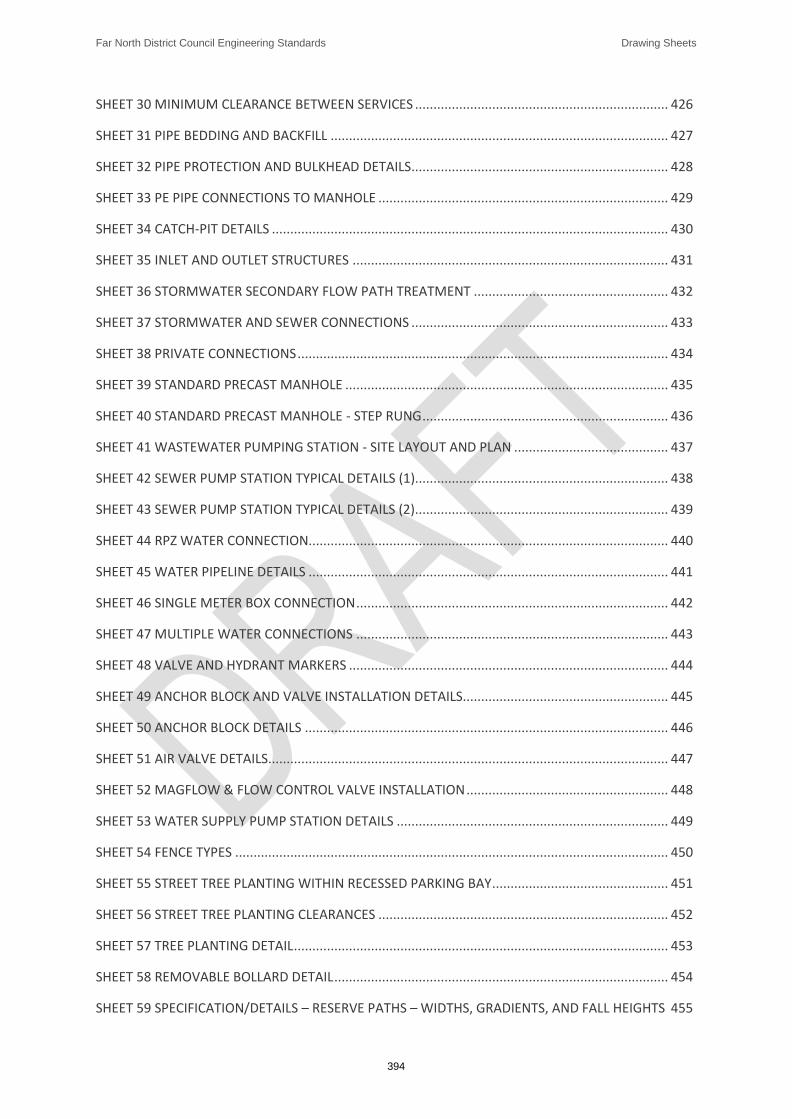
Far North District Council Engineering Standards Drawing Sheets
394
SHEET 30 MINIMUM CLEARANCE BETWEEN SERVICES ..................................................................... 426
SHEET 31 PIPE BEDDING AND BACKFILL ............................................................................................ 427
SHEET 32 PIPE PROTECTION AND BULKHEAD DETAILS ...................................................................... 428
SHEET 33 PE PIPE CONNECTIONS TO MANHOLE ............................................................................... 429
SHEET 34 CATCH-PIT DETAILS ............................................................................................................ 430
SHEET 35 INLET AND OUTLET STRUCTURES ...................................................................................... 431
SHEET 36 STORMWATER SECONDARY FLOW PATH TREATMENT ..................................................... 432
SHEET 37 STORMWATER AND SEWER CONNECTIONS ...................................................................... 433
SHEET 38 PRIVATE CONNECTIONS ..................................................................................................... 434
SHEET 39 STANDARD PRECAST MANHOLE ........................................................................................ 435
SHEET 40 STANDARD PRECAST MANHOLE - STEP RUNG ................................................................... 436
SHEET 41 WASTEWATER PUMPING STATION - SITE LAYOUT AND PLAN .......................................... 437
SHEET 42 SEWER PUMP STATION TYPICAL DETAILS (1)..................................................................... 438
SHEET 43 SEWER PUMP STATION TYPICAL DETAILS (2)..................................................................... 439
SHEET 44 RPZ WATER CONNECTION.................................................................................................. 440
SHEET 45 WATER PIPELINE DETAILS .................................................................................................. 441
SHEET 46 SINGLE METER BOX CONNECTION ..................................................................................... 442
SHEET 47 MULTIPLE WATER CONNECTIONS ..................................................................................... 443
SHEET 48 VALVE AND HYDRANT MARKERS ....................................................................................... 444
SHEET 49 ANCHOR BLOCK AND VALVE INSTALLATION DETAILS........................................................ 445
SHEET 50 ANCHOR BLOCK DETAILS ................................................................................................... 446
SHEET 51 AIR VALVE DETAILS............................................................................................................. 447
SHEET 52 MAGFLOW & FLOW CONTROL VALVE INSTALLATION ....................................................... 448
SHEET 53 WATER SUPPLY PUMP STATION DETAILS .......................................................................... 449
SHEET 54 FENCE TYPES ...................................................................................................................... 450
SHEET 55 STREET TREE PLANTING WITHIN RECESSED PARKING BAY ................................................ 451
SHEET 56 STREET TREE PLANTING CLEARANCES ............................................................................... 452
SHEET 57 TREE PLANTING DETAIL ...................................................................................................... 453
SHEET 58 REMOVABLE BOLLARD DETAIL ........................................................................................... 454
SHEET 59 SPECIFICATION/DETAILS – RESERVE PATHS – WIDTHS, GRADIENTS, AND FALL HEIGHTS 455

Far North District Council Engineering Standards Drawing Sheets
395
SHEET 60 SPECIFICATION/DETAILS – RESERVE PATHS – MATERIAL SPECIFICATIONS AND CONCRETE CUTTING ............................................................................................................................................. 456
SHEET 61 SPECIFICATION/DETAILS – RESERVE PATHS – CONNECTIONS TO ACCESSIBLE CARPARKING AND AMENITIES ................................................................................................................................. 457
SHEET 62 SPECIFICATION/DETAILS – RESERVE PATHS – PATHS AND VEHICLE ACCESSES IN TO RESERVES 458
SHEET 63 SPECIFICATION/DETAILS – RESERVE PATHS – THRESHOLD DESIGN AND VEHICLE BARRIERS 459
SHEET 64 SPECIFICATION/DETAILS – RESERVE FENCING - STANDARD RESERVE FENCING DESIGNS 460
SHEET 65 SPECIFICATION/DETAILS – RESERVE PLAYGROUNDS - SAFETY SURFACING AND EDGING DETAILS FOR ACCESSIBLE PLAYGROUNDS ......................................................................................... 461
SHEET 66 SPECIFICATIONS/DETAILS – STREETSCAPES - PLANTING FOR WATER SENSITIVE DESIGN IN THE STREETSCAPE. ............................................................................................................................. 462
SHEET 67 SPECIFICATIONS/DETAILS – STREETSCAPES - TREE PITS AND TREE PLANTING WITHIN THE ROAD CORRIDOR. ............................................................................................................................... 463
SHEET 68 SPECIFICATION/DETAILS – STREETSCAPES – SERVICE FREE BERM FOR LANDSCAPING PURPOSES, AND UTILITY PLACEMENT. .............................................................................................. 464
SHEET 69 SPECIFICATION/DETAILS – STREETSCAPES – STREET TREE PLANTING CLEARANCES ......... 465
SHEET 70 SPECIFICATIONS/DETAILS – RESERVES AND STREETSCAPES -TREE PLANTING METHODOLOGY AND LANDSCAPE PLANTING AREA PREPARATION. ............................................................................ 466
SHEET 71 SPECIFICATIONS/DETAILS – RESERVES AND STREETSCAPES - LANDSCAPE BEDDING PROFILES AND PREPARATIONS. ......................................................................................................................... 467