WORKBOOK VOL III SAMPLE LAB - INEs3. · · 2012-09-07• Configure the VLAN assignments per the...
29
WORKBOOK VOL III SAMPLE LAB
Transcript of WORKBOOK VOL III SAMPLE LAB - INEs3. · · 2012-09-07• Configure the VLAN assignments per the...

WORKBOOK VOL IIISAMPLE LAB

CCIE Routing & Switching Lab Workbook Volume III Version 4.1 Lab 1
Copyright © 2008 Internetwork Expert www.InternetworkExpert.com - 21 -
IEWB-RS-VOL3 Lab 1
Lab Overview: The following scenario is a practice lab exam designed to help you develop your speed and accuracy at configuring Cisco networking devices. Specifically, this scenario is designed to assist you in your preparation for Cisco Systems’ CCIE Routing and Switching Lab exam. The goal of this scenario is to configure and verify complete layer 2 and layer 3 reachability as quickly as possible while minimizing the usage of Cisco's documentation or the context sensitive help. Ensure to track your time as you progress through each section and compare your results with the specified target time.
Lab Instructions: Prior to starting, ensure that the initial configuration scripts for this lab have been applied. For a current copy of these scripts, see the Internetwork Expert members site at http://members.internetworkexpert.com. Refer to the attached diagrams for interface and protocol assignments. Any reference to X in an address refers to your rack number, while any reference to Y in an address refers to your router number. Upon completion, all devices should have full IP reachability to all networks in the routing domain, including any networks generated by the backbone routers unless explicitly specified.
CCIE Routing & Switching Lab Workbook Volume III Version 4.1 Lab 1
Copyright © 2008 Internetwork Expert www.InternetworkExpert.com - 22 -
Lab Do’s and Don’ts:
• Do not change any interface encapsulations unless otherwise specified • Do not change the console, AUX, and VTY passwords or access methods
unless otherwise specified • Do not use any static routes, default routes, default networks, or policy
routing unless otherwise specified • If any additional IP addresses are needed use IP unnumbered • Save your configurations often
Point Values & Target Times: The point values and target times for each section are as follows:
Section Point Value Target Time
Troubleshooting 2 10 min
Bridging and Switching 10 40 min
WAN Technologies 5 20 min
Interior Gateway Routing 24 1 hr 15 min
Exterior Gateway Routing 8 35 min
GOOD LUCK!
CCIE Routing & Switching Lab Workbook Volume III Version 4.1 Lab 1
Copyright © 2008 Internetwork Expert www.InternetworkExpert.com - 23 -
1. Troubleshooting - (10 Minutes)
1.1. Faults • There are 2 faults with the initial configurations that need to be resolved. • Each fault is worth 1 point • All information (IP addressing, interface numbering, etc) in the diagrams is
correct.
2. Bridging and Switching - (40 Minutes) 2.1. VLAN Assignments • Configure VTP between SW1, SW2, SW3, and SW4 using the domain
name CORE. • SW1 should be the VTP server while the remaining switches should be
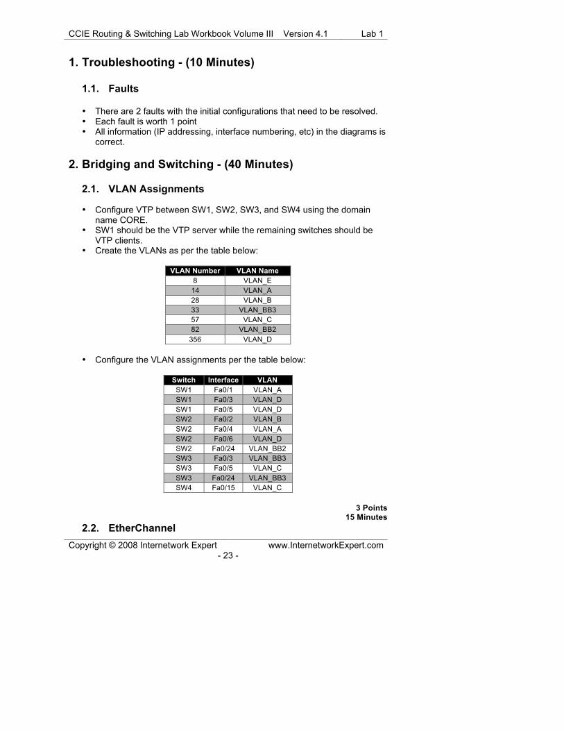
VTP clients. • Create the VLANs as per the table below:
VLAN Number VLAN Name
8 VLAN_E
14 VLAN_A
28 VLAN_B
33 VLAN_BB3
57 VLAN_C
82 VLAN_BB2
356 VLAN_D
• Configure the VLAN assignments per the table below:
Switch Interface VLAN
SW1 Fa0/1 VLAN_A
SW1 Fa0/3 VLAN_D
SW1 Fa0/5 VLAN_D
SW2 Fa0/2 VLAN_B
SW2 Fa0/4 VLAN_A
SW2 Fa0/6 VLAN_D
SW2 Fa0/24 VLAN_BB2
SW3 Fa0/3 VLAN_BB3
SW3 Fa0/5 VLAN_C
SW3 Fa0/24 VLAN_BB3
SW4 Fa0/15 VLAN_C
3 Points
15 Minutes
2.2. EtherChannel

CCIE Routing & Switching Lab Workbook Volume III Version 4.1 Lab 1
Copyright © 2008 Internetwork Expert www.InternetworkExpert.com - 24 -
• Configure interfaces FastEthernet0/13 through FastEthernet0/15 on both
SW1 and SW2 to be bonded as a single logical 802.1q trunk link. • Use the default native VLAN for this connection.
2 Points
10 Minutes
2.3. Trunking • Configure an 802.1q trunk between SW2’s interface FastEthernet0/16 and
SW3’s interface FastEthernet0/16. • Configure two 802.1q trunks between SW2’s interface FastEthernet0/19 &
FastEthernet0/21 and SW4’s interface FastEthernet0/16 & FastEthernet0/18.
2 Points
5 Minutes
2.4. EtherChannel • Create two logical layer 3 connections between SW2 & SW3 and SW3 &
SW4 using all remaining directly connected inter-switch links. • Use PAgP to negotiate these connections. • Use the IP addressing and PortChannel numbering from the diagram.
3 Points
10 Minutes
CCIE Routing & Switching Lab Workbook Volume III Version 4.1 Lab 1
Copyright © 2008 Internetwork Expert www.InternetworkExpert.com - 25 -
3. WAN Technologies – (20 Minutes) 3.1. Hub and Spoke • Configure a Frame Relay hub-and-spoke network between R2, R4, and
R5 with R5 as the hub. • Use only physical interfaces for this configuration. • Use only the DLCIs specified in the diagram. • Do not use Frame Relay Inverse-ARP. • Ensure that all routers can ping each other on this segment.
2 Points
10 Minutes
3.2. Point-to-Point • Configure a Frame Relay connection between R6 and BB1 using DLCI
100. • Use a subinterface numbered .1 on R6 for this connection. • Do not use or disable Frame Relay Inverse-ARP
1 Point
5 Minutes
3.3. PPP Authentication • Configure the Serial connection between R4 and R5 using PPP
encapsulation. • Configure PPP CHAP authentication over the Serial connection between
R4 and R5. • Both routers should use their hostname along with the password CCIE for
authentication.
2 Points 5 Minutes
CCIE Routing & Switching Lab Workbook Volume III Version 4.1 Lab 1
Copyright © 2008 Internetwork Expert www.InternetworkExpert.com - 26 -
4. Interior Gateway Routing – (1 Hour 15 Minutes) 4.1. OSPF over NBMA • Configure OSPF area 0 over the Frame Relay circuit between R2, R4, and
R5. • Use the default OSPF network type for this link. • Ensure that R5 is always elected the Designated Router for this segment.
3 Points
10 Minutes
4.2. OSPF • Configure OSPF area 2 on VLAN_D between R3, R5, and R6. • Configure OSPF area 4 on VLAN_B between R2 and SW2. • Configure OSPF area 4 on the two EtherChannel links between SW2 &
SW3 and SW3 & SW4.
2 Points
10 Minutes
4.3. OSPF Stub Area • Configure OSPF area 3 between R5 and SW1. • This area should be configured as an OSPF stub area.
2 Points
5 Minutes
CCIE Routing & Switching Lab Workbook Volume III Version 4.1 Lab 1
Copyright © 2008 Internetwork Expert www.InternetworkExpert.com - 27 -
4.4. OSPF • Advertise the Loopback0 networks of R4 into OSPF area 0. • Advertise the Loopback0 networks of R3 and R6 into OSPF area 2. • Advertise the Loopback0 networks of R5 and SW1 into OSPF area 3. • Advertise the Loopback0 networks of R2, SW2, SW3, and SW4 into OSPF
area 4. • All of these networks should appear with a subnet mask of /24 in all
routing tables.
3 Points 10 Minutes
4.5. RIP • Configure RIPv2 on R1, R4, R5, and SW1. • Enable RIP between R1 and R4. • Enable RIP on the Serial connection between R4 and R5. • Enable RIP on VLAN_BB2 of SW2. • Authenticate RIP updates coming from and being sent to BB2 using key 1
with the MD5 password CISCO.
3 Points
10 Minutes
4.6. RIP • Advertise R1’s Loopback0 interface into RIP. • Do not use the network command to accomplish this task. • R1’s Loopback0 network should appear with a metric of 10 in R4’s routing
table.
3 Points
5 Minutes

CCIE Routing & Switching Lab Workbook Volume III Version 4.1 Lab 1
Copyright © 2008 Internetwork Expert www.InternetworkExpert.com - 28 -
4.7. Redistribution • Redistribute the VLAN_BB3 network into OSPF on R3. • Redistribute the Frame Relay link network into OSPF on R6. • These prefixes should be seen with a cumulative metric throughout the
OSPF domain.
3 Points
10 Minutes
4.8. Advanced Redistribution • Mutually redistribute between OSPF and RIPv2 on R4, R5, and SW2. • Routers in the OSPF domain should see the RIP routes learned from R4
with a metric of 400 and the RIP routes learned from R5 with a metric of 500.
3 Points
10 Minutes
4.9. Advanced Redistribution • Ensure that reachability to R1’s Loopback0 interface is maintained.
2 Points
5 Minutes

Solutions

CCIE Routing & Switching Lab Workbook Volume III Solutions Guide Version 4.1 Lab 1
Copyright © 2008 Internetwork Expert www.InternetworkExpert.com - 1 -
Task 1.1
Fault 1: The ip subnet-zero command is needed for the 140.X.0.0/25 subnet Fault 2: SW2’s VL82 IP address is 192.1.X.8/24 but should be 192.10.X.8/24 Task 2.1
SW1:
vtp domain CORE ! vlan 8 name VLAN_E vlan 14 name VLAN_A vlan 28 name VLAN_B vlan 33 name VLAN_BB3 vlan 57 name VLAN_C vlan 82 name VLAN_BB2 vlan 356 name VLAN_D ! interface FastEthernet0/1 switchport access vlan 14 switchport mode access ! interface FastEthernet0/3 switchport access vlan 356 switchport mode access ! interface FastEthernet0/5 switchport access vlan 356 switchport mode access
CCIE Routing & Switching Lab Workbook Volume III Solutions Guide Version 4.1 Lab 1
Copyright © 2008 Internetwork Expert www.InternetworkExpert.com - 2 -
SW2:
vtp domain CORE vtp mode client ! interface FastEthernet0/2 switchport access vlan 28 switchport mode access ! interface FastEthernet0/4 switchport access vlan 14 switchport mode access ! interface FastEthernet0/6 switchport access vlan 356 switchport mode access ! interface FastEthernet0/24 switchport access vlan 82 switchport mode access SW3:
vtp domain CORE vtp mode client ! interface FastEthernet0/3 switchport access vlan 33 switchport mode access ! interface FastEthernet0/5 switchport access vlan 57 switchport mode access ! interface FastEthernet0/24 switchport access vlan 33 switchport mode access SW4:
vtp domain CORE vtp mode client ! interface FastEthernet0/15 switchport access vlan 57 switchport mode access no shutdown

CCIE Routing & Switching Lab Workbook Volume III Solutions Guide Version 4.1 Lab 1
Copyright © 2008 Internetwork Expert www.InternetworkExpert.com - 3 -
Task 2.1 Verification
Rack1SW1#show vtp status VTP Version : 2 Configuration Revision : 7 Maximum VLANs supported locally : 1005 Number of existing VLANs : 12 VTP Operating Mode : Server VTP Domain Name : CORE VTP Pruning Mode : Disabled VTP V2 Mode : Disabled VTP Traps Generation : Disabled MD5 digest : 0xCB 0x2B 0x70 0x72 0xD0 0x9A 0x10 0x4F Configuration last modified by 150.1.7.7 at 3-1-93 06:31:32 Local updater ID is 140.1.57.7 on interface Fa0/21 (first layer3 interface found) SW2, SW3, and SW4:
Rack1SWX#show vtp status VTP Version : 2 Configuration Revision : 0 Maximum VLANs supported locally : 1005 Number of existing VLANs : 5 VTP Operating Mode : Client VTP Domain Name : CORE VTP Pruning Mode : Disabled VTP V2 Mode : Disabled VTP Traps Generation : Disabled MD5 digest : 0xF6 0xA0 0x56 0x82 0x84 0xD4 0xBF 0xF6 Configuration last modified by 0.0.0.0 at 0-0-00 00:00:00
Task 2.2
SW1 and SW2:
interface Port-channel1 switchport trunk encapsulation dot1q switchport mode trunk ! interface range FastEthernet0/13 - 15 switchport trunk encapsulation dot1q switchport mode trunk channel-group 1 mode on

CCIE Routing & Switching Lab Workbook Volume III Solutions Guide Version 4.1 Lab 1
Copyright © 2008 Internetwork Expert www.InternetworkExpert.com - 4 -
Task 2.2 Verification
Rack1SW1#show etherchannel summary | begin Group Group Port-channel Protocol Ports ------+-------------+-----------+-------------------------------------- 1 Po1(SU) - Fa0/13(P) Fa0/14(P) Fa0/15(P) Rack1SW1#show interfaces trunk
Port Mode Encapsulation Status Native vlan Po1 on 802.1q trunking 1 Port Vlans allowed on trunk Po1 1-4094 Port Vlans allowed and active in management domain Po1 1,8,14,28,33,57,82,356 Port Vlans in spanning tree forwarding state and not pruned Po1 1,8,14,28,33,57,82,356
Task 2.3
SW2:
interface range Fa0/16, Fa0/19, Fa0/21 switchport trunk encapsulation dot1q switchport mode trunk SW3:
interface FastEthernet0/16 switchport trunk encapsulation dot1q switchport mode trunk SW4:
interface range Fa0/16, Fa0/18 switchport trunk encapsulation dot1q switchport mode trunk
Task 2.3 Verification
Rack1SW2#show interfaces trunk | exclude Po1
Port Mode Encapsulation Status Native vlan Fa0/16 on 802.1q trunking 1 Fa0/19 on 802.1q trunking 1 Fa0/21 on 802.1q trunking 1 Port Vlans allowed on trunk Fa0/16 1-4094 Fa0/19 1-4094 Fa0/21 1-4094 Port Vlans allowed and active in management domain Fa0/16 1,8,14,28,33,57,82,356 Fa0/19 1,8,14,28,33,57,82,356

CCIE Routing & Switching Lab Workbook Volume III Solutions Guide Version 4.1 Lab 1
Copyright © 2008 Internetwork Expert www.InternetworkExpert.com - 5 -
Fa0/21 1,8,14,28,33,57,82,356 Port Vlans in spanning tree forwarding state and not pruned Fa0/16 1,8,14,28,33,57,82,356 Fa0/19 1,8,14,28,33,57,82,356 Fa0/21 none Rack1SW3#show interfaces trunk Port Mode Encapsulation Status Native vlan Fa0/16 on 802.1q trunking 1 Port Vlans allowed on trunk Fa0/16 1-4094 Port Vlans allowed and active in management domain Fa0/16 1,8,14,28,33,57,82,356 Port Vlans in spanning tree forwarding state and not pruned Fa0/16 1,8,14,28,33,57,82,356 Rack1SW4#show interfaces trunk
Port Mode Encapsulation Status Native vlan Fa0/16 on 802.1q trunking 1 Fa0/18 on 802.1q trunking 1 Port Vlans allowed on trunk Fa0/16 1-4094 Fa0/18 1-4094 Port Vlans allowed and active in management domain Fa0/16 1,8,14,28,33,57,82,356 Fa0/18 1,8,14,28,33,57,82,356 Port Vlans in spanning tree forwarding state and not pruned Fa0/16 1,8,14,28,33,57,82,356 Fa0/18 1,8,14,28,33,57,82,356
Task 2.4
SW2:
interface Port-channel23 no switchport ip address 140.1.0.8 255.255.255.128
SW2 and SW3:
interface range FastEthernet0/17 - 18 no switchport channel-group 23 mode desirable no shutdown
CCIE Routing & Switching Lab Workbook Volume III Solutions Guide Version 4.1 Lab 1
Copyright © 2008 Internetwork Expert www.InternetworkExpert.com - 6 -
SW3:
interface Port-channel23 no switchport ip address 140.1.0.9 255.255.255.128 ! interface Port-channel34 no switchport ip address 140.1.0.129 255.255.255.128
SW4:
interface Port-channel34 no switchport ip address 140.1.0.130 255.255.255.128
SW3 and SW4:
interface range FastEthernet0/19 - 21 no switchport channel-group 34 mode desirable no shutdown
Task 2.4 Verification
Below is the Po23 configuration done in the correct “order of
operations” for configuring a layer 3 Etherchannel link:
Rack1SW2#conf t Enter configuration commands, one per line. End with CNTL/Z. Rack1SW2(config)#interface range fa0/17 - 18 Rack1SW2(config-if-range)#no switchport Rack1SW2(config-if-range)#channel-group 23 mode desirable Creating a port-channel interface Port-channel 23 Rack1SW2(config-if-range)#interface po 23 % Command exited out of interface range and its sub-modes. Not executing the command for second and later interfaces Rack1SW2(config-if)#no switchport Rack1SW2(config-if)#ip address 140.1.0.8 255.255.255.128 Rack1SW2(config-if)# Rack1AS>9 [Resuming connection 9 to sw3 ... ] Rack1SW3#conf t Enter configuration commands, one per line. End with CNTL/Z. Rack1SW3(config)#interface range fa0/17 - 18 Rack1SW3(config-if-range)#no switchport Rack1SW3(config-if-range)#channel-group 23 mode desirable Creating a port-channel interface Port-channel 23 Rack1SW3(config-if-range)#interface po 23 % Command exited out of interface range and its sub-modes. Not executing the command for second and later interfaces Rack1SW3(config-if)#ip address 140.1.0.9 255.255.255.128 Rack1SW3(config-if)#interface range fa0/17 - 18 Rack1SW3(config-if-range)#no shutdown 00:07:24: %LINK-3-UPDOWN: Interface FastEthernet0/17, changed state to down

CCIE Routing & Switching Lab Workbook Volume III Solutions Guide Version 4.1 Lab 1
Copyright © 2008 Internetwork Expert www.InternetworkExpert.com - 7 -
00:07:24: %LINK-3-UPDOWN: Interface FastEthernet0/18, changed state to down 00:07:25: %LINEPROTO-5-UPDOWN: Line protocol on Interface FastEthernet0/17, changed state to down 00:07:25: %LINEPROTO-5-UPDOWN: Line protocol on Interface FastEthernet0/18, changed state to down Rack1SW3(config-if-range)# Rack1AS>8 [Resuming connection 8 to sw2 ... ] Rack1SW2(config-if)#interface range fa0/17 - 18 Rack1SW2(config-if-range)#no shutdown Rack1SW2(config-if-range)# 00:07:52: %LINK-3-UPDOWN: Interface FastEthernet0/17, changed state to up 00:07:52: %LINK-3-UPDOWN: Interface FastEthernet0/18, changed state to up 00:07:54: %LINEPROTO-5-UPDOWN: Line protocol on Interface FastEthernet0/18, changed state to up 00:07:54: %LINEPROTO-5-UPDOWN: Line protocol on Interface FastEthernet0/17, changed state to up 00:07:55: %LINK-3-UPDOWN: Interface Port-channel23, changed state to up 00:07:56: %LINEPROTO-5-UPDOWN: Line protocol on Interface Portchannel23, changed state to up Rack1SW2(config-if-range)#^Z 00:07:58: %SYS-5-CONFIG_I: Configured from console by console Rack1SW2#ping 140.1.0.9 Type escape sequence to abort. Sending 5, 100-byte ICMP Echos to 140.1.0.9, timeout is 2 seconds: .!!!! Success rate is 80 percent (4/5), round-trip min/avg/max = 1/1/1 ms Rack1SW2#show etherchannel summary | begin Group Group Port-channel Protocol Ports ------+-------------+-----------+-------------------------------------- --------- 23 Po23(RU) PAgP Fa0/17(P) Fa0/18(P) Rack1SW2#
CCIE Routing & Switching Lab Workbook Volume III Solutions Guide Version 4.1 Lab 1
Copyright © 2008 Internetwork Expert www.InternetworkExpert.com - 8 -
Task 3.1
R2:
interface Serial0/0 ip address 140.1.245.2 255.255.255.0 frame-relay map ip 140.1.245.4 205 frame-relay map ip 140.1.245.5 205 broadcast no frame-relay inverse-arp
R4:
interface Serial0/0 ip address 140.1.245.4 255.255.255.0 frame-relay map ip 140.1.245.2 405 frame-relay map ip 140.1.245.5 405 broadcast no frame-relay inverse-arp
R5:
interface Serial0/0 ip address 140.1.245.5 255.255.255.0 frame-relay map ip 140.1.245.2 502 broadcast frame-relay map ip 140.1.245.4 504 broadcast no frame-relay inverse-arp
Task 3.1 Verification Rack1R5#show frame-relay map Serial0/0 (up): ip 140.1.245.2 dlci 502(0x1F6,0x7C60), static, broadcast, CISCO, status defined, active Serial0/0 (up): ip 140.1.245.4 dlci 504(0x1F8,0x7C80), static, broadcast, CISCO, status defined, active Rack1R5#ping 140.1.245.2 Type escape sequence to abort. Sending 5, 100-byte ICMP Echos to 140.1.245.2, timeout is 2 seconds: ..!!! Success rate is 60 percent (3/5), round-trip min/avg/max = 32/32/32 ms Rack1R5#ping 140.1.245.4 Type escape sequence to abort. Sending 5, 100-byte ICMP Echos to 140.1.245.4, timeout is 2 seconds: !!!!! Success rate is 100 percent (5/5), round-trip min/avg/max = 56/59/60 ms

CCIE Routing & Switching Lab Workbook Volume III Solutions Guide Version 4.1 Lab 1
Copyright © 2008 Internetwork Expert www.InternetworkExpert.com - 9 -
Task 3.2
R6:
interface Serial0/0/0 no ip address encapsulation frame-relay ! interface Serial0/0/0.1 point-to-point ip address 54.1.2.6 255.255.255.0 frame-relay interface-dlci 100
Task 3.2 Verification Rack1R6#show frame-relay map Serial0/0/0.1 (up):point-to-point dlci, dlci 100(0x64,0x1840),broadcast status defined, active Rack1R6#ping 54.1.2.254 Type escape sequence to abort. Sending 5, 100-byte ICMP Echos to 54.1.2.254, timeout is 2 seconds: !!!!! Success rate is 100 percent (5/5), round-trip min/avg/max = 32/32/32 ms

CCIE Routing & Switching Lab Workbook Volume III Solutions Guide Version 4.1 Lab 1
Copyright © 2008 Internetwork Expert www.InternetworkExpert.com - 10 -
Task 3.3
R4:
username Rack1R5 password 0 CISCO ! interface Serial0/1 encapsulation ppp ppp authentication chap
R5:
username Rack1R4 password 0 CISCO ! interface Serial0/1 encapsulation ppp ppp authentication chap clockrate 64000
Task 3.3 Verification Rack1R4#show interfaces s0/1 Serial0/1 is up, line protocol is up Hardware is QUICC Serial Internet address is 140.1.45.4/24 MTU 1500 bytes, BW 1544 Kbit, DLY 20000 usec, reliability 255/255, txload 1/255, rxload 1/255 Encapsulation PPP, LCP Open Open: CDPCP, IPCP, loopback not set <output omitted> Rack1R4#ping 140.1.45.5 Type escape sequence to abort. Sending 5, 100-byte ICMP Echos to 140.1.45.5, timeout is 2 seconds: !!!!! Success rate is 100 percent (5/5), round-trip min/avg/max = 28/28/32 ms
Verify PPP authentication:
Rack1R5#debug ppp authentication PPP authentication debugging is on Rack1R5#conf t Enter configuration commands, one per line. End with CNTL/Z. Rack1R5(config)#interface s0/1 Rack1R5(config-if)#shutdown %LINK-5-CHANGED: Interface Serial0/1, changed state to administratively down %LINEPROTO-5-UPDOWN: Line protocol on Interface Serial0/1, changed state to down Rack1R5(config-if)#no shutdown %LINK-3-UPDOWN: Interface Serial0/1, changed state to up Se0/1 PPP: Using default call direction Se0/1 PPP: Treating connection as a dedicated line Se0/1 PPP: Session handle[A6000008] Session id[7] Se0/1 PPP: Authorization required Se0/1 CHAP: O CHALLENGE id 1 len 28 from "Rack1R5"

CCIE Routing & Switching Lab Workbook Volume III Solutions Guide Version 4.1 Lab 1
Copyright © 2008 Internetwork Expert www.InternetworkExpert.com - 11 -
Se0/1 CHAP: I CHALLENGE id 6 len 28 from "Rack1R4" Se0/1 CHAP: Using hostname from unknown source Se0/1 CHAP: Using password from AAA Se0/1 CHAP: O RESPONSE id 6 len 28 from "Rack1R5" Se0/1 CHAP: I RESPONSE id 1 len 28 from "Rack1R4" Se0/1 PPP: Sent CHAP LOGIN Request Se0/1 PPP: Received LOGIN Response PASS Se0/1 PPP: Sent LCP AUTHOR Request Se0/1 PPP: Sent IPCP AUTHOR Request Se0/1 LCP: Received AAA AUTHOR Response PASS Se0/1 CHAP: I SUCCESS id 6 len 4 Se0/1 IPCP: Received AAA AUTHOR Response PASS Se0/1 CHAP: O SUCCESS id 1 len 4 Se0/1 PPP: Sent CDPCP AUTHOR Request Se0/1 CDPCP: Received AAA AUTHOR Response PASS Se0/1 PPP: Sent IPCP AUTHOR Request %LINEPROTO-5-UPDOWN: Line protocol on Interface Serial0/1, changed state to up
Task 4.1
R2:
interface Serial0/0 ip ospf priority 0 ! router ospf 1 router-id 150.1.2.2 network 140.1.245.2 0.0.0.0 area 0
R4:
interface Serial0/0 ip ospf priority 0 ! router ospf 1 router-id 150.1.4.4 network 140.1.245.4 0.0.0.0 area 0
R5:
router ospf 1 router-id 150.1.5.5 network 140.1.245.5 0.0.0.0 area 0 neighbor 140.1.245.2 neighbor 140.1.245.4

CCIE Routing & Switching Lab Workbook Volume III Solutions Guide Version 4.1 Lab 1
Copyright © 2008 Internetwork Expert www.InternetworkExpert.com - 12 -
Task 4.1 Verification
Verify OSPF neighbors and confirm that R5 is the DR:
Rack1R5#show ip ospf neighbor Neighbor ID Pri State Dead Time Address Interface 150.1.2.2 0 FULL/DROTHER 00:01:52 140.1.245.2 Serial0/0 150.1.4.4 0 FULL/DROTHER 00:01:52 140.1.245.4 Serial0/0 Verify that R2 and R4 could not participate in DR/BDR election:
Rack1R2#show ip ospf interface s0/0 | include Pri Transmit Delay is 1 sec, State DROTHER, Priority 0 Rack1R4#show ip ospf interface s0/0 | include Pri Transmit Delay is 1 sec, State DROTHER, Priority 0
Task 4.2
R2:
router ospf 1 network 140.1.28.2 0.0.0.0 area 4
R3:
router ospf 1 network 140.1.100.3 0.0.0.0 area 2
R5:
router ospf 1 network 140.1.100.5 0.0.0.0 area 2
R6:
router ospf 1 network 140.1.100.6 0.0.0.0 area 2
SW2:
ip routing ! router ospf 1 router-id 150.1.8.8 network 140.1.0.8 0.0.0.0 area 4 network 140.1.28.8 0.0.0.0 area 4
SW3:
ip routing ! router ospf 1 router-id 150.1.9.9 network 140.1.0.9 0.0.0.0 area 4 network 140.1.0.129 0.0.0.0 area 4

CCIE Routing & Switching Lab Workbook Volume III Solutions Guide Version 4.1 Lab 1
Copyright © 2008 Internetwork Expert www.InternetworkExpert.com - 13 -
SW4:
ip routing ! router ospf 1 router-id 150.1.10.10 network 140.1.0.130 0.0.0.0 area 4
Task 4.2 Verification
Verify OSPF neighbors on all OSPF routers. For instance on R5 and R2:
Rack1R5#show ip ospf neighbor Neighbor ID Pri State Dead Time Address Interface 150.1.2.2 0 FULL/DROTHER 00:01:38 140.1.245.2 Serial0/0 150.1.4.4 0 FULL/DROTHER 00:01:56 140.1.245.4 Serial0/0 150.1.3.3 1 FULL/DROTHER 00:00:37 140.1.0.3 Ethernet0/0 150.1.6.6 1 FULL/DR 00:00:39 140.1.0.6 Ethernet0/0 Rack1R2#show ip ospf neighbor Neighbor ID Pri State Dead Time Address Interface 150.1.5.5 1 FULL/DR 00:01:51 140.1.245.5 Serial0/0 150.1.8.8 1 FULL/BDR 00:00:30 140.1.28.8 FastEthernet0/0
Task 4.3
SW1:
ip routing ! router ospf 1 router-id 150.1.7.7 area 3 stub network 140.1.57.7 0.0.0.0 area 3
R5:
router ospf 1 area 3 stub network 140.1.57.5 0.0.0.0 area 3
Task 4.3 Verification
Verify OSPF neighbors on SW1:
Rack1SW1#show ip ospf neighbor Neighbor ID Pri State Dead Time Address Interface 150.1.5.5 1 FULL/DR 00:00:39 140.1.57.5 FastEthernet0/21

CCIE Routing & Switching Lab Workbook Volume III Solutions Guide Version 4.1 Lab 1
Copyright © 2008 Internetwork Expert www.InternetworkExpert.com - 14 -
Confirm that Area 3 is a stub area:
Rack1SW1#show ip ospf | beg Area 3 Area 3 Number of interfaces in this area is 1 It is a stub area Area has no authentication SPF algorithm last executed 00:00:06.584 ago SPF algorithm executed 3 times Area ranges are Number of LSA 7. Checksum Sum 0x035AED Number of opaque link LSA 0. Checksum Sum 0x000000 Number of DCbitless LSA 0 Number of indication LSA 0 Number of DoNotAge LSA 0 Flood list length 0
Verify the OSPF routes on SW1:
Rack1SW1#show ip route ospf 140.1.0.0/24 is subnetted, 4 subnets O IA 140.1.245.0 [110/65] via 140.1.57.5, 00:13:08, FastEthernet0/21 O IA 140.1.28.0 [110/66] via 140.1.57.5, 00:13:08, FastEthernet0/21 O IA 140.1.100.0 [110/11] via 140.1.57.5, 00:03:05, FastEthernet0/21 O*IA 0.0.0.0/0 [110/2] via 140.1.57.5, 00:13:08, FastEthernet0/21
Task 4.4
R2:
interface Loopback0 ip ospf network point-to-point ! router ospf 1 network 150.1.2.2 0.0.0.0 area 4
R3:
interface Loopback0 ip ospf network point-to-point ! router ospf 1 network 150.1.3.3 0.0.0.0 area 2
R4:
interface Loopback0 ip ospf network point-to-point ! router ospf 1 network 150.1.4.4 0.0.0.0 area 0
R5:
interface Loopback0 ip ospf network point-to-point ! router ospf 1 network 150.1.5.5 0.0.0.0 area 3
CCIE Routing & Switching Lab Workbook Volume III Solutions Guide Version 4.1 Lab 1
Copyright © 2008 Internetwork Expert www.InternetworkExpert.com - 15 -
R6:
interface Loopback0 ip ospf network point-to-point ! router ospf 1 network 150.1.6.6 0.0.0.0 area 2
SW1:
interface Loopback0 ip ospf network point-to-point ! router ospf 1 network 150.1.7.7 0.0.0.0 area 3
SW2:
interface Loopback0 ip ospf network point-to-point ! router ospf 1 network 150.1.8.8 0.0.0.0 area 4
SW3:
interface Loopback0 ip ospf network point-to-point ! router ospf 1 network 150.1.9.9 0.0.0.0 area 4
SW4:
interface Loopback0 ip ospf network point-to-point ! router ospf 1 network 150.1.10.10 0.0.0.0 area 4
Task 4.4 Verification
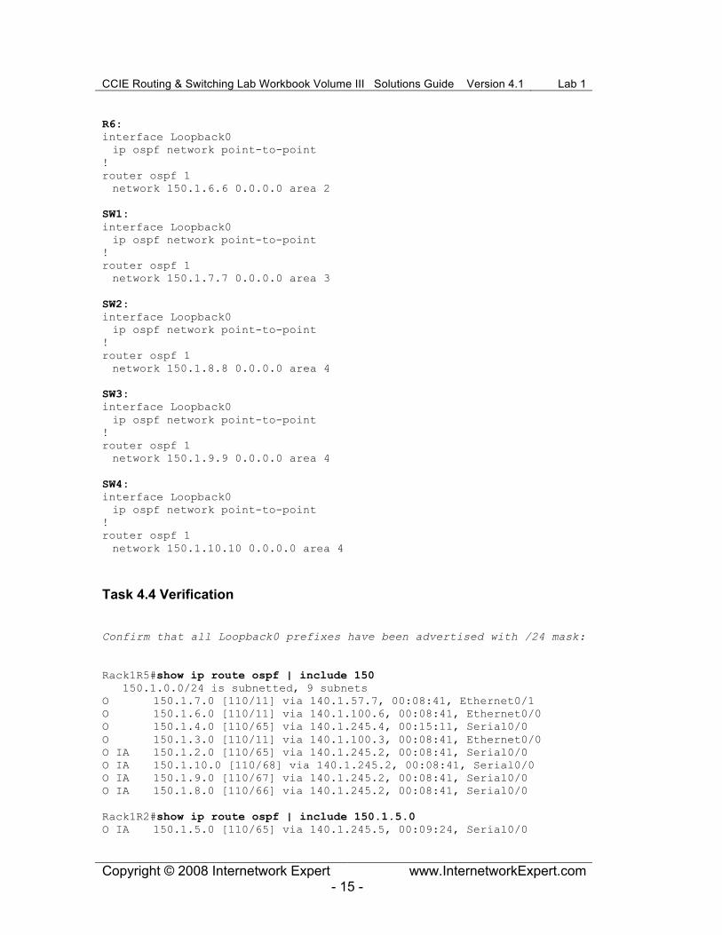
Confirm that all Loopback0 prefixes have been advertised with /24 mask:
Rack1R5#show ip route ospf | include 150 150.1.0.0/24 is subnetted, 9 subnets O 150.1.7.0 [110/11] via 140.1.57.7, 00:08:41, Ethernet0/1 O 150.1.6.0 [110/11] via 140.1.100.6, 00:08:41, Ethernet0/0 O 150.1.4.0 [110/65] via 140.1.245.4, 00:15:11, Serial0/0 O 150.1.3.0 [110/11] via 140.1.100.3, 00:08:41, Ethernet0/0 O IA 150.1.2.0 [110/65] via 140.1.245.2, 00:08:41, Serial0/0 O IA 150.1.10.0 [110/68] via 140.1.245.2, 00:08:41, Serial0/0 O IA 150.1.9.0 [110/67] via 140.1.245.2, 00:08:41, Serial0/0 O IA 150.1.8.0 [110/66] via 140.1.245.2, 00:08:41, Serial0/0 Rack1R2#show ip route ospf | include 150.1.5.0 O IA 150.1.5.0 [110/65] via 140.1.245.5, 00:09:24, Serial0/0

CCIE Routing & Switching Lab Workbook Volume III Solutions Guide Version 4.1 Lab 1
Copyright © 2008 Internetwork Expert www.InternetworkExpert.com - 16 -
Task 4.5
R1:
router rip version 2 network 140.1.0.0 no auto-summary
R4:
router rip version 2 passive-interface default no passive-interface Ethernet0/0 no passive-interface Serial0/1 network 140.1.0.0 no auto-summary
R5:
router rip version 2 passive-interface default no passive-interface Serial0/1 network 140.1.0.0 no auto-summary
SW2:
key chain RIP_KEY key 1 key-string CISCO ! interface Vlan82 ip rip authentication mode md5 ip rip authentication key-chain RIP_KEY ! router rip version 2 network 192.10.1.0 no auto-summary
Task 4.5 Verification Rack1SW2#show ip rout rip R 222.22.2.0/24 [120/7] via 192.10.1.254, 00:00:04, Vlan82 R 220.20.3.0/24 [120/7] via 192.10.1.254, 00:00:04, Vlan82 R 205.90.31.0/24 [120/7] via 192.10.1.254, 00:00:04, Vlan82 Rack1R1#show ip route rip 140.1.0.0/16 is variably subnetted, 4 subnets, 2 masks R 140.1.245.0/24 [120/1] via 140.1.14.4, 00:00:05, FastEthernet0/0 R 140.1.45.0/24 [120/1] via 140.1.14.4, 00:00:05, FastEthernet0/0 R 140.1.45.5/32 [120/1] via 140.1.14.4, 00:00:05, FastEthernet0/0
CCIE Routing & Switching Lab Workbook Volume III Solutions Guide Version 4.1 Lab 1
Copyright © 2008 Internetwork Expert www.InternetworkExpert.com - 17 -
Task 4.6
R1:
router rip redistribute connected metric 10 route-map CONNECTED->RIP ! route-map CONNECTED->RIP permit 10 match interface Loopback0
Task 4.6 Verification
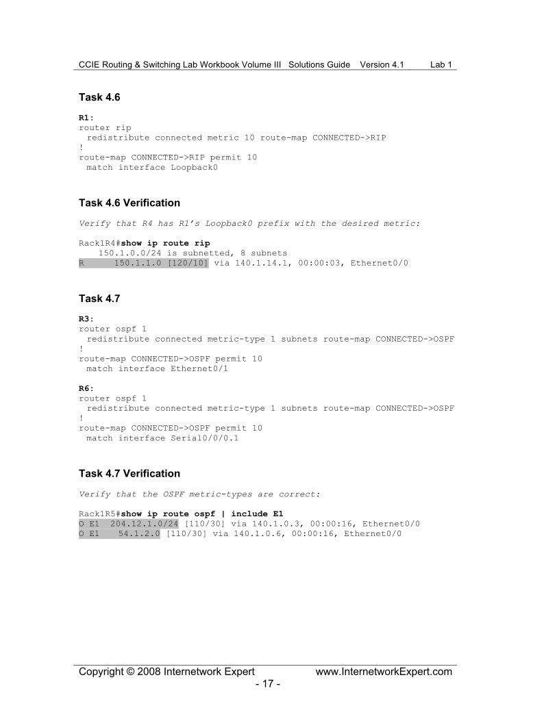
Verify that R4 has R1’s Loopback0 prefix with the desired metric:
Rack1R4#show ip route rip 150.1.0.0/24 is subnetted, 8 subnets R 150.1.1.0 [120/10] via 140.1.14.1, 00:00:03, Ethernet0/0
Task 4.7
R3:
router ospf 1 redistribute connected metric-type 1 subnets route-map CONNECTED->OSPF ! route-map CONNECTED->OSPF permit 10 match interface Ethernet0/1
R6:
router ospf 1 redistribute connected metric-type 1 subnets route-map CONNECTED->OSPF ! route-map CONNECTED->OSPF permit 10 match interface Serial0/0/0.1
Task 4.7 Verification
Verify that the OSPF metric-types are correct:
Rack1R5#show ip route ospf | include E1 O E1 204.12.1.0/24 [110/30] via 140.1.0.3, 00:00:16, Ethernet0/0 O E1 54.1.2.0 [110/30] via 140.1.0.6, 00:00:16, Ethernet0/0

CCIE Routing & Switching Lab Workbook Volume III Solutions Guide Version 4.1 Lab 1
Copyright © 2008 Internetwork Expert www.InternetworkExpert.com - 18 -
Task 4.8
R4:
router ospf 1 redistribute rip subnets route-map RIP->OSPF ! router rip redistribute ospf 1 metric 1 ! route-map RIP->OSPF permit 10 set metric 400
R5:
router ospf 1 redistribute rip subnets route-map RIP->OSPF ! router rip redistribute ospf 1 metric 1 ! route-map RIP->OSPF permit 10 set metric 500
SW2:
router ospf 1 redistribute rip subnets ! router rip redistribute ospf 1 metric 1
Task 4.8 Verification
Routes learned via R4:
Rack1R2#show ip route | include 400 O E2 140.1.14.0/24 [110/400] via 140.1.245.4, 00:06:53, Serial0/0 O E2 140.1.45.0/24 [110/400] via 140.1.245.4, 00:06:53, Serial0/0 O E2 140.1.45.5/32 [110/400] via 140.1.245.4, 00:06:53, Serial0/0 O E2 150.1.1.0 [110/400] via 140.1.245.4, 00:04:28, Serial0/0
Routes learned via R5:
Rack1R2#show ip route | include 500 O E2 140.1.45.4/32 [110/500] via 140.1.245.5, 00:06:58, Serial0/0
Task 4.9
R5:
router rip redistribute ospf 1 metric 1 route-map OSPF->RIP ! access-list 1 deny 150.1.1.0 access-list 1 permit any ! route-map OSPF->RIP permit 10 match ip address 1

CCIE Routing & Switching Lab Workbook Volume III Solutions Guide Version 4.1 Lab 1
Copyright © 2008 Internetwork Expert www.InternetworkExpert.com - 19 -
Task 4.9 Verification
Rack1R4#show ip route 150.1.1.1 Routing entry for 150.1.1.0/24 Known via "rip", distance 120, metric 10 Redistributing via ospf 1, rip Advertised by ospf 1 subnets route-map RIP->OSPF Last update from 140.1.14.1 on Ethernet0/0, 00:00:11 ago Routing Descriptor Blocks: * 140.1.14.1, from 140.1.14.1, 00:00:11 ago, via Ethernet0/0 Route metric is 10, traffic share count is 1
Verify full internal connectivity as well as connectivity to backbone
IGP prefixes with the following TCL script:
foreach i { 140.1.14.1 150.1.1.1 140.1.245.2 140.1.28.2 150.1.2.2 140.1.100.3 150.1.3.3 204.12.1.3 140.1.245.4 140.1.14.4 150.1.4.4 140.1.45.4 140.1.245.5 140.1.100.5 150.1.5.5 140.1.45.5 140.1.57.5 54.1.2.6 140.1.100.6 150.1.6.6 150.1.7.7 140.1.57.7 150.1.8.8 140.1.28.8 140.1.0.8 192.10.1.8 150.1.9.9 140.1.0.9 140.1.0.129 140.1.0.130 150.1.10.10 222.22.2.1 220.20.3.1 205.90.31.1 } { puts [exec "ping $i"] }
Note that VLAN8 is excluded from connectivity test since it’s not part
of any IGP.