Workbench with Riser Shelf and Backpanel - The Home …€¦ · · 2017-04-27Workbench with Riser...
8
"A" "C" "C" End Panel Top Shelf Bottom Shelf Support channel End Panel "A" "A" "A" Center panel Top rail Top rail Fasteners (Shown full size) Quantity Type 54 3/8" 1/2" 5/8" 1/2" 1" 1/4" 12.7mm 25.4mm 6.35mm 12.7mm 15.87mm 9.52mm "A" "B" "C" "D" "E" "F" "G" 8 40 14 4 4 8 1/2" 12.7mm R Workbench with Riser Shelf and Backpanel Assembly Instructions Note: The galvanized steel parts sometimes retain a slight protective coating after the manufacturing process. You may want to wipe the coating off the parts with a clean dry cloth before assembling the unit. 1. Do not tighten any fasteners until all the workbench components in step 1 and 2 are assembled together. Assemble each of the two shelves to the end panels using 16 type "A" fasteners per shelf, 4 at each corner and 4 type "C" fasteners per shelf, two on each end of the shelf. Note: The two shelves are interchangable for assembly. Attach the support channel to the bottom shelf using 4 type "C" fasteners, two at the front of the shelf and two at the back. 2. Assemble the center panel to the top shelf using 2 type "A" fasteners. (You will find the center panel packed inside one of the drawers) Assemble the two top rails using 10 type "A" fasteners per rail, 4 at each end and 2 in the center to the center panel. Note: The two top rails are interchangable for assembly. Tighten all the fasteners used in step 1 and 2. 1 2 HUSKY-524 9027-0601 1 8
Transcript of Workbench with Riser Shelf and Backpanel - The Home …€¦ · · 2017-04-27Workbench with Riser...

"A"
"C"
"C"
End Panel
Top Shelf
Bottom Shelf
Support channel
End Panel
"A"
"A"
"A"
Centerpanel
Top rail
Top rail
Fasteners(Shown fullsize)
Quantity
Type
54
3/8"1/2" 5/8" 1/2" 1"
1/4"12.7mm
25.4mm6.35mm
12.7mm 15.87mm9.52mm
"A" "B" "C" "D" "E" "F" "G"8 40 14 4 4 8
1/2"12.7mm
R
Workbench with Riser Shelf and Backpanel Assembly Instructions
Note: The galvanized steel parts sometimes retain a slight protective coating after the manufacturing process. You may want to wipe the coating off the parts with a clean dry cloth before assembling the unit.
1.Do not tighten any fasteners until all the workbench components in step 1 and 2 are assembled together.
Assemble each of the two shelves to the end panels using 16 type "A" fasteners per shelf, 4 at each corner and 4 type "C" fasteners per shelf, two on each end of the shelf. Note: The two shelves are interchangable for assembly.
Attach the support channel to the bottom shelf using 4 type "C" fasteners, two at the front of the shelf and two at the back.
2.Assemble the center panel to the top shelf using 2 type "A" fasteners. (You will find the center panel packed inside one of the drawers)
Assemble the two top rails using 10 type "A" fasteners per rail, 4 at each end and 2 in the center to the center panel. Note: The two top rails are interchangable for assembly.
Tighten all the fasteners used in step 1 and 2.
1
2HUSKY-5249027-0601
18

Figure 5.1 Figure 5.2
Bracket
Roller Glide
"G"
"G"
"C"
Figure 5.4
Figure 5.3
Roller glides
Back of unit
Front of unit
Lower drawer position if both drawers are installed on one side of the center panel.
3.The galvanized steel covering on the top comes with a protective plastic film. To help protect the metal surface while assembling the unit leave this film in place. The plastic will be removed at step 7 in order to assemble the riser posts to the top.
Place the top on a clean surface on the floor with the steel side facing down. Turn the workbench frame over and center it on the top using the corner dimensions shown in the illustration.
Locate the 10 mounting holes on the frame, (2 on each end panel, 2 on each rail and 2 on the center panel). Mark the location of these holes and remove the frame.
Drill 10 pilot holes at the marked locations 1/8" (3.17 mm) diameter x 1/2" (12.7 mm) deep. Assemble the frame to the top using 10 type "D" fasteners.
Now you can turn the workbench upright to complete the assembly.
4.Attach the 4 roller glides to their brackets. Slide the internal roller glide extensions all the way forward until the front mounting hole is accessable. Attach the roller glide to the bracket with 2 type "G" fasteners each.
5.The two drawers may be installed across the top of the workbench frame on both sides of the center panel using the top sets of mounting holes (figure 5.1) or they may both be installed on one side of the center panel using both upper and lower sets of mounting holes (figure 5.2) Determine which configuration you would prefer before assembling the roller glides to the frame.
You must install the roller glide assemblies so the drawers pull out towards the front of the workbench. The back corners of the top have the wood core exposed on both the side and back edge (figure 5.3).
When assembling the roller glide assembly to the frame make sure the glide is positioned so the internal glide members will extend out towards the front of the workbench (figure 5.4)
For each drawer, assemble one roller glide assembly to the end panel and one opposing roller glide assembly to the center panel using 2 type "C" fasteners for each roller glide assembly.
3
4
5HUSKY-5249027-0601
28
2-1/2"63mm
2-1/2"63mm
1-1/4"32mm
1-1/4"32mm
"D"
Top

Internal glidemembers
Figure 1
Drawer
Tab
Drawer rail
6.To install the drawers on the roller glides first pull out the two internal glide extensions of the roller glides as far as possible (figure 1).
Align both rails attached to the drawer with the internal extensions of the roller glides and push the drawer in until it is locked in place.
SEE MAINTENANCE FOR DRAWER REMOVAL
The base of the workbench is now complete.
7Remove the protective plastic cover from the metal top.
Install the 2 riser posts on the rear corners of the top. The posts must be pushed snugly on each corner. Mark the 2 locations of the holes in the bottom flanges of each riser post and drill (2) 1/8" (3.17 mm) diameter x 1/2" (12.7 mm) deep pilot holes in the bottom side of the workbench top.
With the post pushed snugly on the corner, fasten to the bottom side of the top using 2 type "D" fasteners. Assemble the sides tabs to the side and back edge of the wood core of the top using 2 type "F" self drilling fasteners.
8.Assemble the front rail to the riser posts using 4 type "C" fasteners, 2 at each corner.
Assemble the back rail to the riser posts using 4 type "C" fasteners, 2 at each corner.8
7
6
HUSKY-5249027-0601
38
"F"
"F"
"D"
Riser post
"C"
"C"
Back Rail
Front Rail

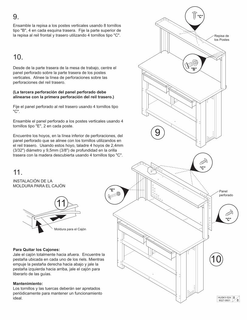
9.Assemble the shelf to the two posts using 8 type "B" fasteners, 4 on each back corner. Attach the top of the shelf to the front rail and back rail with 4 type "C" fasteners.
11.TRIM INSTALLATION
10.From the back of the workbench, center the pegboard panel over the back of the riser assembly. Align the top row of holes in the pegboard over the lower set of holes in the back rail.
(The third hole in the pegboard panel must align with the first hole in the back rail)
Assemble the pegboard panel to the back rail using 4 type "C" fasteners.
Assemble the pegboard panel to the back of the riser posts using 4 type "E" fasteners, 2 in each post.
Locate the holes, in the bottom row of holes, in the pegboard that align with the fasteners used on the back rail. Using these hole locations, drill 4 pilot holes 3/32" (2.38 mm) diameter x 3/8" (9.52 mm) deep in the back edge of the wood core of the top. Assemble the pegboard panel to the back edge of the wood core of the top using 4 type "C" fasteners.
Drawer Removal:To remove the drawer, pull the drawer all the way out. Locate the tab on each of the drawer rails. While holding down the right tab and holding up the left tab, pull the drawer off the roller glides.
Maintenance:Hardware (nuts, bolts, screws) should be tightened periodically to maintain trouble free operation.
For customer service help in the United States call: 1-800-323-9601
10
9
HUSKY-5249027-0601
48
"C"
"B"
Riser shelf
"C"
"C"
"E" Pegboard panel
Drawer trim
11

"A"
"A"
"A"
PanelCentralReilSuperior
Reil Superior
Sujetadores(mostradostamano real)
Cantidad
Tipo
54
3/8"1/2" 5/8" 1/2" 1"
1/4"12,7mm
25,4mm6,35mm
12,7mm 15,87mm9,52mm
"A" "B" "C" "D" "E" "F" "G"8 40 14 4 4 8
1/2"12,7mm
R
Mesa de Trabajo con Repisa y Pared Instrucciones de Ensamblado
Nota: Las partes de acero galvanizado a veces retienen una capa a ligera de la cubierta protectora después del proceso de fabricación. Tal vez desee guitar esta capa con un trapo limpio y seco antes de ensamblar la unidad.
1.No apriete los sujetadores hasta que todos los componentes de los pasos 1 y 2 hayan sido ensamblados.
Ensamble cada repisa a los extremos laterales con (16) tornillos tipo "A" por cada repisa (4 en cada esquina) y (4) tornillos tipo "C" por cada repisa, dos en cada extremo. Nota: Las dos repisas son intercambiables para ensamblar.
Atornille la barra de soporte a la repisa inferior con (4) tornillos tipo "C", dos hacia el frente y dos en la parte de atrás.
2.Ensamble el panel central a la repisa superior con (2) tornillos tipo "A". (Usted encontrará el panel central dentro de uno de los cajones)
Ensamble cada riel superior usando (10) tornillos tipo "A" cada uno, 4 en cada extremo y 2 para fijar al centro del panel central. Nota: Los dos rieles superiores son intercambiables para ensainblar.
Apriete todos los sujetadores utilizados en los pasos 1 y 2.
1
2HUSKY-5249027-0601
58
"A"
"C"
"C"
Panel Extremo Lateral
RepisaSuperior
RepisaInferior
Barra deSoporte
Panel Extremo Lateral

Figura 5,1 Figura 5,2
Guía paraCajón
"G"
"G"
"C"
Figura 5,4
Figure 5.3
Guías paraCajónes
Parte Posteriorde la Unidad
Frente de la Unidad
Baje la posición del cajón si los dos cajones quedarán instalados de un mismo lado del panel central.
3.La cubierta de acero galvanizado en la parte superior tiene una película de plástico protectora. Deje esta película en su lugar durante el ensamblado de la unidad para proteger la superficie metálica. El plástico se quitará en el paso 7 cuando ensamble los postes verticales.
Coloque la parte superior en el suelo sobre una superficie limpia con el acero hacia abajo. Voltee la mesa de trabajo y colóquela sobre la parte superior utilizando las dimensiones mostradas.
Encuentre las 10 perforaciones en la estructura, (2 en cada extremo lateral, 2 en cada riel y 2 en el panel central). Marque la ubicación de estas perforaciones y quite la estructura.
Taladre 10 hoyos en los lugares marcados, 3,2mm (1/8") en diámetro y 12,7mm (1/2") de profundidad. Ensamble la estructura utilizando 10 tornillos tipo "D'.
Ahora Usted podrá voltear la mesa de trabajo en posición verticale para poder terminar.
4.Fije las 4 guías para los cajones sobre sus soportes. Deslice las extensiones de la guía interna totalmente hacia el frente hasta que quede accesible la perforación para montar. Fije cada guía al soporte con dos tornillos tipo "G" cada una.
5.Los dos cajones pueden instalarse uno de cada lado del panel central utilizando las perforaciones superiores (Figura 5,1) o pueden ser instalados de un solo lado del panel central utilizando ambos juegos de perforaciones (superiores e inferiores, Figura 5,2). Determine cual configuración desea antes de ensamblar las guías para los cajones.
Debe instalar las guías para los cajones de manera que los cajones salagan hacia el frente de la unidad. Las esquinas traseras de la parte superior tienen la madera expuesta en las orillas laterales y traseras. (Figurar 5,3)
Cuando ensamble las guías para los cajones a la estructura, asegurase de que la guía este posicionada de manera que los miembros internos de la guía se extiendan hacia el frente de la unidad (Figura 5,4).
Para cada cajón, fije una guía para cajón al panel extremo lateral y otra al panel central utilizando 2 tornillos tipo "C" por cada guía.
3
4
5HUSKY-5249027-0601
68
2-1/2"63mm
2-1/2"63mm
1-1/4"32mm
1-1/4"32mm
"D"
ParteSuperior
Soportepara Guías

Miembros internos de la guía
Figura 1
Cajón
Pestaña
Reil para Cajón
6.Para instalar los cajones a las guías, primero jale las extensiones internar de las guías lo mas posible hacia delante. (Figura 1)
Alinee ambos rieles que están fijados al cajón con las extensiones de las guías y empuje cada cajón hacia dentro hasta que quede fijo en su lugar.
VÉASE LA SECCIÓN DE "MANTENIMIENTO" PARA SCARA CAJONES
La base de la mesa de trabajo está completa.
7Quite la cubierta protectora de la parte superior metálica.
Instale los 2 postes verticales en cada una de las 2 equinas traseras. Los postes deben quedar justos en cada esquina. Marque las 2 ubicaciones de las perforaciones en la parte inferior de cada poste y taladre (2) hoyo, de 3,2mm (1/8") de diámetro y 12,7mm (1/2") de profundidad, dentro de la parte inferior de la superficie de la mesa de trabajo.
Aplique presión al postes para quede justo en sobre la esquina y fije usando dos tornillos tipo "D" a través de la parte inferior de la superficie de la mesa de trabajo. Ensamble las pestañas de los postes por encima de la madera descubierta en las orillas laterales y traseras de la superficie de la mesa de trabajo utilizando 2 tornillos tipo "F" (sin necesidad de hacer un hoyo primer).
8.Fije el reil frontal a los postes verticales usando 4 tornillos tipo "C", 2 en cada esquina.
Fije el reil trasero a los postes verticales usando 4 tornillos tipo "C", 2 en cada esquina.8
7
6
HUSKY-5249027-0601
78
"F"
"F"
"D"
Poste Verticale
"C"
"C"
Reil trasero
Reil frontal
9.Ensamble la repisa a los postes verticales usando 8 tornillos tipo "B", 4 en cada esquina trasera. Fije la parte superior de la repisa al reil frontal y trasero utilizando 4 tornillos tipo "C".
11.INSTALACIÓN DE LAMOLDURA PARA EL CAJÓN
10.Desde de la parte trasera de la mesa de trabajo, centre el panel perforado sobre la parte trasera de los postes verticales. Alinee la línea de perforaciones sobre las perforaciones del reil trasero.
(La tercera perforación del panel perforado debe alinearse con la primera perforación del reil trasero.)
Fije el panel perforado al reil trasero usando 4 tornillos tipo "C".
Ensamble el panel perforado a los postes verticales usando 4 tornillos tipo "E", 2 en cada poste.
Encuentre los hoyos, en la línea inferior de perforaciones, del panel perforado que se alinee con los tornillos utilizandos en el reil trasero. Usando estos hoyo, taladre 4 hoyos de 2,4mm (3/32") diámetro y 9,5mm (3/8") de profundidad en la orilla trasera con la madera descubierta usando 4 tornillos tipo "C".
Para Quitar los Cajones:Jale el cajón totalmente hacia afuera. Encuentre la pestaña ubicada en cada uno de los riels. Mientras empuje la pestaña derecha hacia abajo y jale la pestaña izquierda hacia arriba, jale el cajón para liberarlo de las guías.
Mantenimiento:Los tornillos y las tuercas deberán ser apretados periódicamente para mantener un funcionamiento ideal.
10
9
HUSKY-5249027-0601
88
"C"
"B"
Repisa de los Postes
"C"
"C"
"E" Panelperforado
Moldura para el Cajón
11


![Drilling Riser[1]](https://static.fdocuments.in/doc/165x107/55267215550346d36e8b4d99/drilling-riser1.jpg)