Workbench LS-DYNA Supported Keywords
56
Workbench LS-DYNA Supported Keywords Release 18.1 ANSYS, Inc. April 2017 Southpointe 2600 ANSYS Drive Canonsburg, PA 15317 ANSYS, Inc. and ANSYS Europe, [email protected] Ltd. are UL http://www.ansys.com registered ISO (T) 724-746-3304 (F) 724-514-9494 9001: 2008 companies.
Transcript of Workbench LS-DYNA Supported Keywords

Workbench LS-DYNA Supported Keywords
Release 18.1ANSYS, Inc.April 2017Southpointe
2600 ANSYS DriveCanonsburg, PA 15317 ANSYS, Inc. and
ANSYS Europe,[email protected]. are UL
http://www.ansys.com registered ISO(T) 724-746-3304(F) 724-514-9494
9001: 2008companies.

Copyright and Trademark Information
© 2017 ANSYS, Inc. Unauthorized use, distribution or duplication is prohibited.
ANSYS, ANSYS Workbench, AUTODYN, CFX, FLUENT and any and all ANSYS, Inc. brand, product, service and featurenames, logos and slogans are registered trademarks or trademarks of ANSYS, Inc. or its subsidiaries located in theUnited States or other countries. ICEM CFD is a trademark used by ANSYS, Inc. under license. CFX is a trademarkof Sony Corporation in Japan. All other brand, product, service and feature names or trademarks are the propertyof their respective owners. FLEMlm and FLEXnet are trademarks of Flexera Software LLC.
Disclaimer Notice
THIS ANSYS SOFTWARE PRODUCT AND PROGRAM DOCUMENTATION INCLUDE TRADE SECRETS AND ARE CONFID-ENTIAL AND PROPRIETARY PRODUCTS OF ANSYS, INC., ITS SUBSIDIARIES, OR LICENSORS. The software productsand documentation are furnished by ANSYS, Inc., its subsidiaries, or affiliates under a software license agreementthat contains provisions concerning non-disclosure, copying, length and nature of use, compliance with exportinglaws, warranties, disclaimers, limitations of liability, and remedies, and other provisions. The software productsand documentation may be used, disclosed, transferred, or copied only in accordance with the terms and conditionsof that software license agreement.
ANSYS, Inc. and ANSYS Europe, Ltd. are UL registered ISO 9001: 2008 companies.
U.S. Government Rights
For U.S. Government users, except as specifically granted by the ANSYS, Inc. software license agreement, the use,duplication, or disclosure by the United States Government is subject to restrictions stated in the ANSYS, Inc.software license agreement and FAR 12.212 (for non-DOD licenses).
Third-Party Software
See the legal information in the product help files for the complete Legal Notice for ANSYS proprietary softwareand third-party software. If you are unable to access the Legal Notice, contact ANSYS, Inc.
Published in the U.S.A.

Table of Contents
1. Supported LS-DYNA Keywords . . . . . . . . . . . . . . . . . . . . . . . . . . . . . . . . . . . . . . . . . . . . . . . . . . . . . . . . . . . . . . . . . . . . . . . . . . . . . . . . . . . . . . . . . . . . . . . . . . . . . . . . . . . . . . . 11.1. Input File Header .... . . . . . . . . . . . . . . . . . . . . . . . . . . . . . . . . . . . . . . . . . . . . . . . . . . . . . . . . . . . . . . . . . . . . . . . . . . . . . . . . . . . . . . . . . . . . . . . . . . . . . . . . . . . . . . . . . . . . . . . . . . 11.2. Database Format .... . . . . . . . . . . . . . . . . . . . . . . . . . . . . . . . . . . . . . . . . . . . . . . . . . . . . . . . . . . . . . . . . . . . . . . . . . . . . . . . . . . . . . . . . . . . . . . . . . . . . . . . . . . . . . . . . . . . . . . . . . . 21.3. Control Cards .... . . . . . . . . . . . . . . . . . . . . . . . . . . . . . . . . . . . . . . . . . . . . . . . . . . . . . . . . . . . . . . . . . . . . . . . . . . . . . . . . . . . . . . . . . . . . . . . . . . . . . . . . . . . . . . . . . . . . . . . . . . . . . . . . 21.4. Part Setup .... . . . . . . . . . . . . . . . . . . . . . . . . . . . . . . . . . . . . . . . . . . . . . . . . . . . . . . . . . . . . . . . . . . . . . . . . . . . . . . . . . . . . . . . . . . . . . . . . . . . . . . . . . . . . . . . . . . . . . . . . . . . . . . . . . . . . 91.5. Engineering Data Materials and Equations of State .... . . . . . . . . . . . . . . . . . . . . . . . . . . . . . . . . . . . . . . . . . . . . . . . . . . . . . . . . . . . . . . . . . . . . . . 161.6. Mesh Definition .... . . . . . . . . . . . . . . . . . . . . . . . . . . . . . . . . . . . . . . . . . . . . . . . . . . . . . . . . . . . . . . . . . . . . . . . . . . . . . . . . . . . . . . . . . . . . . . . . . . . . . . . . . . . . . . . . . . . . . . . . . . 261.7. Coordinate Systems .... . . . . . . . . . . . . . . . . . . . . . . . . . . . . . . . . . . . . . . . . . . . . . . . . . . . . . . . . . . . . . . . . . . . . . . . . . . . . . . . . . . . . . . . . . . . . . . . . . . . . . . . . . . . . . . . . . . . . 291.8. Components and Named Selections .... . . . . . . . . . . . . . . . . . . . . . . . . . . . . . . . . . . . . . . . . . . . . . . . . . . . . . . . . . . . . . . . . . . . . . . . . . . . . . . . . . . . . . . . . . . . . 301.9. Remote Points and Point Masses .... . . . . . . . . . . . . . . . . . . . . . . . . . . . . . . . . . . . . . . . . . . . . . . . . . . . . . . . . . . . . . . . . . . . . . . . . . . . . . . . . . . . . . . . . . . . . . . . . . 311.10. Contacts and Body Interactions .... . . . . . . . . . . . . . . . . . . . . . . . . . . . . . . . . . . . . . . . . . . . . . . . . . . . . . . . . . . . . . . . . . . . . . . . . . . . . . . . . . . . . . . . . . . . . . . . . . 34
1.10.1. Keywords Created from the Contact Properties Object ... . . . . . . . . . . . . . . . . . . . . . . . . . . . . . . . . . . . . . . . . . . . . . . . . . . . . . . . 381.11. Magnitude and Tabular Data .... . . . . . . . . . . . . . . . . . . . . . . . . . . . . . . . . . . . . . . . . . . . . . . . . . . . . . . . . . . . . . . . . . . . . . . . . . . . . . . . . . . . . . . . . . . . . . . . . . . . . . 401.12. Acceleration and Gravity .... . . . . . . . . . . . . . . . . . . . . . . . . . . . . . . . . . . . . . . . . . . . . . . . . . . . . . . . . . . . . . . . . . . . . . . . . . . . . . . . . . . . . . . . . . . . . . . . . . . . . . . . . . . . 401.13. Supports ... . . . . . . . . . . . . . . . . . . . . . . . . . . . . . . . . . . . . . . . . . . . . . . . . . . . . . . . . . . . . . . . . . . . . . . . . . . . . . . . . . . . . . . . . . . . . . . . . . . . . . . . . . . . . . . . . . . . . . . . . . . . . . . . . . . . . 411.14. Loads .... . . . . . . . . . . . . . . . . . . . . . . . . . . . . . . . . . . . . . . . . . . . . . . . . . . . . . . . . . . . . . . . . . . . . . . . . . . . . . . . . . . . . . . . . . . . . . . . . . . . . . . . . . . . . . . . . . . . . . . . . . . . . . . . . . . . . . . . . 421.15. Discrete Connections .... . . . . . . . . . . . . . . . . . . . . . . . . . . . . . . . . . . . . . . . . . . . . . . . . . . . . . . . . . . . . . . . . . . . . . . . . . . . . . . . . . . . . . . . . . . . . . . . . . . . . . . . . . . . . . . . . 431.16. Other Supports ... . . . . . . . . . . . . . . . . . . . . . . . . . . . . . . . . . . . . . . . . . . . . . . . . . . . . . . . . . . . . . . . . . . . . . . . . . . . . . . . . . . . . . . . . . . . . . . . . . . . . . . . . . . . . . . . . . . . . . . . . . . 441.17. Environment Temperature .... . . . . . . . . . . . . . . . . . . . . . . . . . . . . . . . . . . . . . . . . . . . . . . . . . . . . . . . . . . . . . . . . . . . . . . . . . . . . . . . . . . . . . . . . . . . . . . . . . . . . . . . . . 451.18. ASCII Files ... . . . . . . . . . . . . . . . . . . . . . . . . . . . . . . . . . . . . . . . . . . . . . . . . . . . . . . . . . . . . . . . . . . . . . . . . . . . . . . . . . . . . . . . . . . . . . . . . . . . . . . . . . . . . . . . . . . . . . . . . . . . . . . . . . . 451.19. Database Output Settings .... . . . . . . . . . . . . . . . . . . . . . . . . . . . . . . . . . . . . . . . . . . . . . . . . . . . . . . . . . . . . . . . . . . . . . . . . . . . . . . . . . . . . . . . . . . . . . . . . . . . . . . . . . 481.20. End of Input File ... . . . . . . . . . . . . . . . . . . . . . . . . . . . . . . . . . . . . . . . . . . . . . . . . . . . . . . . . . . . . . . . . . . . . . . . . . . . . . . . . . . . . . . . . . . . . . . . . . . . . . . . . . . . . . . . . . . . . . . . . . 49
Index .... . . . . . . . . . . . . . . . . . . . . . . . . . . . . . . . . . . . . . . . . . . . . . . . . . . . . . . . . . . . . . . . . . . . . . . . . . . . . . . . . . . . . . . . . . . . . . . . . . . . . . . . . . . . . . . . . . . . . . . . . . . . . . . . . . . . . . . . . . . . . . . . . . . . . . . 51
iiiRelease 18.1 - © ANSYS, Inc. All rights reserved. - Contains proprietary and confidential information
of ANSYS, Inc. and its subsidiaries and affiliates.

Release 18.1 - © ANSYS, Inc. All rights reserved. - Contains proprietary and confidential informationof ANSYS, Inc. and its subsidiaries and affiliates.iv
Chapter 1: Supported LS-DYNA Keywords
The Workbench LS-DYNA ACT extension allows you to run an explicit dynamics analysis for your modelusing the LS-DYNA solver.
This section shows all LS-DYNA supported keywords and their syntax. This applies to supported keywordsfor resumed projects that used the LS-DYNA (Export) system. The keyword file follows the same formatas the corresponding Mechanical APDL application. Keywords conform to the "LS_DYNA Keyword User'sManual" versions 970 and 971 (version 971 has particular features for the handling of beam cross sectionand integration options).
Each keyword consists of one or more cards, each with one of more parameters. If a parameter is notshown, it will be assigned default values by the LS-DYNA solver. In addition some descriptions toWorkbench features that do not relate directly to keywords are given at the end of this section, entitledGeneral Descriptions.
This chapter describes the following:1.1. Input File Header1.2. Database Format1.3. Control Cards1.4. Part Setup1.5. Engineering Data Materials and Equations of State1.6. Mesh Definition1.7. Coordinate Systems1.8. Components and Named Selections1.9. Remote Points and Point Masses1.10. Contacts and Body Interactions1.11. Magnitude and Tabular Data1.12. Acceleration and Gravity1.13. Supports1.14. Loads1.15. Discrete Connections1.16. Other Supports1.17. Environment Temperature1.18. ASCII Files1.19. Database Output Settings1.20. End of Input File
1.1. Input File Header
*KEYWORD
Marks the beginning of a keyword file.
1Release 18.1 - © ANSYS, Inc. All rights reserved. - Contains proprietary and confidential information
of ANSYS, Inc. and its subsidiaries and affiliates.

1.2. Database Format
*DATABASE_FORMAT
Specifies the format in which to write binary results files like D3PLOT and D3THDT.
Card
• IFORM = 0. Binary results will be written only in the LS-DYNA format.
• IFORM = 2. Both LS-DYNA and ANSYS database formats will be written.
• IBINARY = 0. Word size of the binary output files (D3PLOT, D3THDT, ...) defaults to 64 bit format.
1.3. Control Cards
*CONTROL_ACCURACY
Specifies control parameters that can improve the accuracy of the calculation.
Card
• OSU = 1. Global flag for objective stress updates. Required for parts that undergo large rotations. When setto 1 the flag is on.
• INN = 4. Invariant node numbering for shell and solid elements. When set to 4 the flag is on for both shelland solid elements.
*CONTROL_ALE
Set global control parameters for the Arbitrary Lagrange-Eulerian (ALE) and Eulerian calculations.
Card
• DCT = Continuum Treatment from the ALE Controls section of the Analysis Settings (Defaults to 1):
– = 1 if the Continuum Treatment is set to Lagrangian.
– = 2 if the Continuum Treatment is set to Eulerian.
– = 3 if the Continuum Treatment is set to Arbitrary Lagrangian Eulerian.
– = 4 if the Continuum Treatment is set to Eulerian Ambiant.
• NDV = Cycles Between Advection from the ALE Controls section of the Analysis Settings (Default to 1).
• METH = Advection Method from the ALE Controls section of the Analysis Settings (Default to 1):
Release 18.1 - © ANSYS, Inc. All rights reserved. - Contains proprietary and confidential informationof ANSYS, Inc. and its subsidiaries and affiliates.2
Supported LS-DYNA Keywords

= 1 if the Advection Method is set to Donor cell + Half-Index-Shift METH.–
– = 2 if the Advection Method is set to Van Leer + Half-Index-Shift.
*CONTROL_BULK_VISCOSITY
Sets the bulk viscosity coefficients globally.
Card
• Q1 = 1.5. Quadratic Artificial Viscosity.
• Q2 = 0.06. Linear Artificial Viscosity.
• TYPE = -2. Internal energy dissipated by the viscosity in the shell elements is computed and included in theoverall energy balance.
*CONTROL_CONTACT
Specifies the defaults for computations of contact surfaces.
Card 1
• SLSFAC = 0 (uses the default = 0.1). Scale factor for sliding interface penalties.
• RWPNAL = 0. Scale factor for rigid wall penalties. When equal to 0 the constrain method is used and nodalpoints which belong to rigid bodies are not considered.
• ISLCHK = 1. Initial penetration check in contact surfaces. When set to 1 there is no checking.
• SHLTHK = 1 (default). Shell thickness considered in surface to surface and node to surface contact types.When set to 1, thickness is considered but rigid bodies are excluded.
• PENOPT = 1 (default). Penalty stiffness value option.
• THKCHG = 0 (default).
• ORIEN = 2. Automatic reorientation for contact segments during initialization. When set to 2 it is active formanual (segment) and automated (part) input.
• ENMASS = 0. This parameter regulates the treatment of the mass for eroded nodes in contact. When set to0 eroding nodes are removed from the calculation.
Card 2
• USRSTR = 0. Storage per contact interface for user supplied interface control subroutine. When set to 0 noinput data is read and no interface storage is permitted in the user subroutine.
• Default values are used for all other parameters.
Card3
• SFRIC = 0. Default static coefficient of friction.
• Default values are used for all other parameters.
3Release 18.1 - © ANSYS, Inc. All rights reserved. - Contains proprietary and confidential information
of ANSYS, Inc. and its subsidiaries and affiliates.
Control Cards

Card4
• IGNORE = 2. Specifies whether to ignore initial penetrations in the *CONTACT_AUTOMATIC options. Whenset to 2 initial penetrations are allowed to exist by tracking them. Also, warning messages are printed withthe original and the recommended coordinates of each slave node.
• FRCENG = 1. Calculate frictional energy in contact. Convert mechanical frictional energy to heat when doinga coupled thermal-mechanical problem.
• SKIPRWG = 0 (default).
• OUTSEG = 1. Yes, output each beam spot weld slave node and its master segment for *CONTACT_SPOTWELDinto D3HSP file.
• SPOTSTP = 0 (default).
• SPOTDEL = 1.Yes, delete the attached spot weld element if the nodes of a spot weld beam or solid elementare attached to a shell element that fails and the nodes are deleted.
• SPOTHIN = 0.5. This factor can be used to scale the thickness of parts within the vicinity of the spot weld.This factor helps avert premature weld failures due to contact of the welded parts with the weld itself. Shouldbe greater than zero and less than one.
*CONTROL_ENERGY
Specifies the controls for energy dissipation options.
Card
• HGEN = 2. Hourglass energy is computed and included in the energy balance. Results are reported in ASCIIfiles GLSTAT and MATSUM.
• RWEN = 2 (default).
• SLNTEN = 2. Sliding interface energy dissipation is computed and included in the energy balance. Resultsare reported in ASCII files GLSTAT and SLEOUT.
• RYLEN = 2. Rayleigh energy dissipation is computed and included in the energy balance. Results are reportedin ASCII file GLSTAT.
*CONTROL_HOURGLASS
Defines the default values of hourglass control type and coefficient.
Card
• IHQ = Default Hourglass from the Hourglass Controls section of the Analysis Settings ( Default to 1 andStandard LS-DYNA Hourglass ):
Release 18.1 - © ANSYS, Inc. All rights reserved. - Contains proprietary and confidential informationof ANSYS, Inc. and its subsidiaries and affiliates.4
Supported LS-DYNA Keywords

= 1 if the Default Hourglass is set to Standard LS-DYNA.–
– = 2 if the Default Hourglass is set to Flanagan-Belytschko Viscous Form.
– = 3 if the Default Hourglass is set to Exact Volume Flanagan-Belytschko.
– = 4 if the Default Hourglass is set to Flanagan-Belytschko Stiffness Form.
– = 5 if the Default Hourglass is set to Exact Volume Flanagan-Belytschko Stiffness Form.
– = 6 if the Default Hourglass is set to Belytschko-Bindeman IHQ.
– = 7 if the Default Hourglass is set to Belytschko-Bindeman Linear Total Strain.
• QH = Default Hourglass Coefficient from the Hourglass Controls section of the Analysis Settings ( Defaultto 0.1 ).
*CONTROL_OUTPUT
This keyword controls the printing of various LS-DYNA output text files.
Card
• NPOPT is the only parameter that is set. The value is set to 1. With that parameter set, nodal coordinates,element connectivities, rigid wall definitions, nodal SPCs, initial velocities, initial strains,adaptive constraints,and SPR2/SPR3 constraints are not printed.
*CONTROL_PARALLEL
Controls parallel processing usage for shared memory computers by defining the number of processorsand invoking the optional consistency of the global vector assembly.
Card
• CONST = 1. Consistency flag disabled for a faster solution
*CONTROL_SOLUTION
Specify the analysis solution procedure if thermal, coupled thermal analysis, or structural-only is per-formed.
Card
• SOLN
– = 0. Structural analysis only, if the Solver Type is set to Program Controlled or Structural Analysis Only.
– = 2. Coupled structural thermal analysis, if the Solver Type is set to Coupled Structural Thermal Analysis.
*CONTROL_SHELL
Specifies global parameters for shell element types.
Card
5Release 18.1 - © ANSYS, Inc. All rights reserved. - Contains proprietary and confidential information
of ANSYS, Inc. and its subsidiaries and affiliates.
Control Cards

• WRPANG = 20 (default). Shell element warpage angle in degrees. If a warpage greater than this angle isfound, a warning message is printed.
• ESORT = 1, full automatic sorting of triangular shell elements to treat degenerate quadrilateral shell elements
as C0 triangular shells.
• IRNXX = -1, shell normal update option. When set to -1, fiber directions are recomputed at each cycle.
• ISTUPD = 4, shell thickness update option for deformable shells. Membrane strains cause changes in thicknessin 3 and 4 node shell elements, however elastic strains are neglected. This option is very important in sheetmetal forming or whenever membrane stretching is important. For crash analysis, setting 4 may improveenergy conservation and stability.
• THEORY = 2 (default). Belytschko-Tsay formulation.
• BWC = 1. For this setting, Belytschko-Wong-Chiang warping stiffness is added.
• MITER = 1 (default). Plane stress plasticity: iterative with 3 secant iterations.
• PROJ = 1, the full projection method is used for the warping stiffness in the Belytschko-Tsay and Belytschko-Wong-Chiang shell elements. This option is required for explicit calculations.
• NFAIL1 = 1. Flag to check for highly distorted under-integrated shell elements, print a message, and deletethe element.
• NFAIL4 = 1. Flag to check for highly distorted fully-integrated shell elements, print a message, and deletethe element.
• CNTO = 2. Flag to account for shell reference surface offsets in the contact treatment. Offsets are treatedusing the user defined contact thickness which may be different than the shell thickness used in the element.
*CONTROL_SOLID
Specifies global parameters for solid element types.
Card
• ESORT = 1, full automatic sorting of tetrahedron and pentahedron elements to treat degeneracies. Degen-erate tetrahedrons will be treated as ELFORM = 10 and pentahedron as ELFORM = 15 solids respectively(see *SECTION_SOLID).
*CONTROL_TERMINATION
Specifies the termination criteria for the solver.
Card
• ENDTIM = End Time in the Step Controls section of the Analysis Settings.
• ENDCYC = 10000000(constant) Maximum Time Steps.
• DTMIN = 0.001 (constant).
• ENDENG = 1000 (constant) Maximum Energy Error.
Release 18.1 - © ANSYS, Inc. All rights reserved. - Contains proprietary and confidential informationof ANSYS, Inc. and its subsidiaries and affiliates.6
Supported LS-DYNA Keywords

• ENDMAS = 100000 (constant) Maximum Part Scaling.
*CONTROL_THERMAL_TIMESTEP
This keyword is written if the simulation is determined to be a thermal one (for example, CoupledStructural Thermal Analysis). See Solver Type from the Solver Controls section of the Analysis Settings.
Card
• TS = Auto Time Stepping from Thermal Step Controls (default to 1):
– 0 if Auto Time Stepping from Thermal Step Controls is set to No. The time step is fixed.
– 1 if Auto Time Stepping from Thermal Step Controls is set to Yes. The time step is variable (may increaseor decrease).
• TIP = Time integration parameter from Thermal Step Controls (default to Crank Nicholson Scheme TIP =0):
– 0 if Time integration parameter from Thermal Step Controls is set to Crank-Nicholson scheme.
– 1 if Time integration parameter from Thermal Step Controls is set to Fully Implicit.
• ITS = Initial Time Step from Thermal Step Controls.
• TMIN = Minimum Time Step from Thermal Step Controls. If TMIN = 0.0, it is set to the structural explicittime step.
• TMAX = Maximum Time Step from Thermal Step Controls. If TMAX = 0.0, it is set to 100 * the structuralexplicit time step.
*CONTROL_THERMAL_SOLVER
This keyword is written if the simulation is determined to be a thermal one (for example, CoupledStructural Thermal Analysis). See Solver Type from the Solver Controls section of the Analysis Settings.
Card
• ATYPE = Thermal Analysis Type from Thermal Solver Controls (default to 1)
7Release 18.1 - © ANSYS, Inc. All rights reserved. - Contains proprietary and confidential information
of ANSYS, Inc. and its subsidiaries and affiliates.
Control Cards

0 if Thermal Analysis Type from Thermal Solver Controls is set to Steady State Analysis.–
– 1 if Thermal Analysis Type from Thermal Solver Controls is set to Transient Analysis.
• SOLVER = Solver Type from Thermal Solver Controls (defaults to 1):
– 1 if Solver Type is set to Symmetric Direct Solver.
– 2 if Solver Type is set to Nonsymmetric Direct Solver.
– 3 if Solver Type is set to Diagonal Scaled Conjugate Gradient Iterative.
– 4 if Solver Type is set to Incomplete Choleski Conjugate Gradient Iterative.
– 5 if Solver Type is set to Nonsymmetric Diagonal Scaled bi-Conjugate Gradient.
– 12 if Solver Type is set to Diagonal Scaling Conjugate Gradient Iterative.
– 13 if Solver Type is set to Symmetric Gauss-Siedel Conjugate Gradient Iterative.
– 14 if Solver Type is set to SSOR Conjugate Gradient Iterative.
– 15 if Solver Type is set to ILDLT0 Conjugate Gradient Iterative.
– 16 if Solver Type is set to Modified ILDLT0 Conjugate Gradient Iterative.
• PTYPE = Thermal problem type from Thermal Nonlinear Controls.
– 0 if Thermal problem type is set to Linear Problem.
– 1 if Thermal problem type is set to Nonlinear problem Gauss Point Temperature.
– 2 if Thermal problem type is set to Nonlinear problem Element Average Temperature.
• FWORK = Fraction of Work Converted into Heat from Thermal Solver Controls (defaults to 1).
*CONTROL_THERMAL_NONLINEAR
This keyword is written if the simulation is determined to be a thermal one (for example, CoupledStructural Thermal Analysis). See Solver Type from the Solver Controls section of the Analysis Settings.
Card
• THLSTL = Line Search from Thermal Nonlinear Controls (defaults to 0.0)
Release 18.1 - © ANSYS, Inc. All rights reserved. - Contains proprietary and confidential informationof ANSYS, Inc. and its subsidiaries and affiliates.8
Supported LS-DYNA Keywords
• TOL = Temperature Convergence from Thermal Nonlinear Controls (defaults to 0.0).
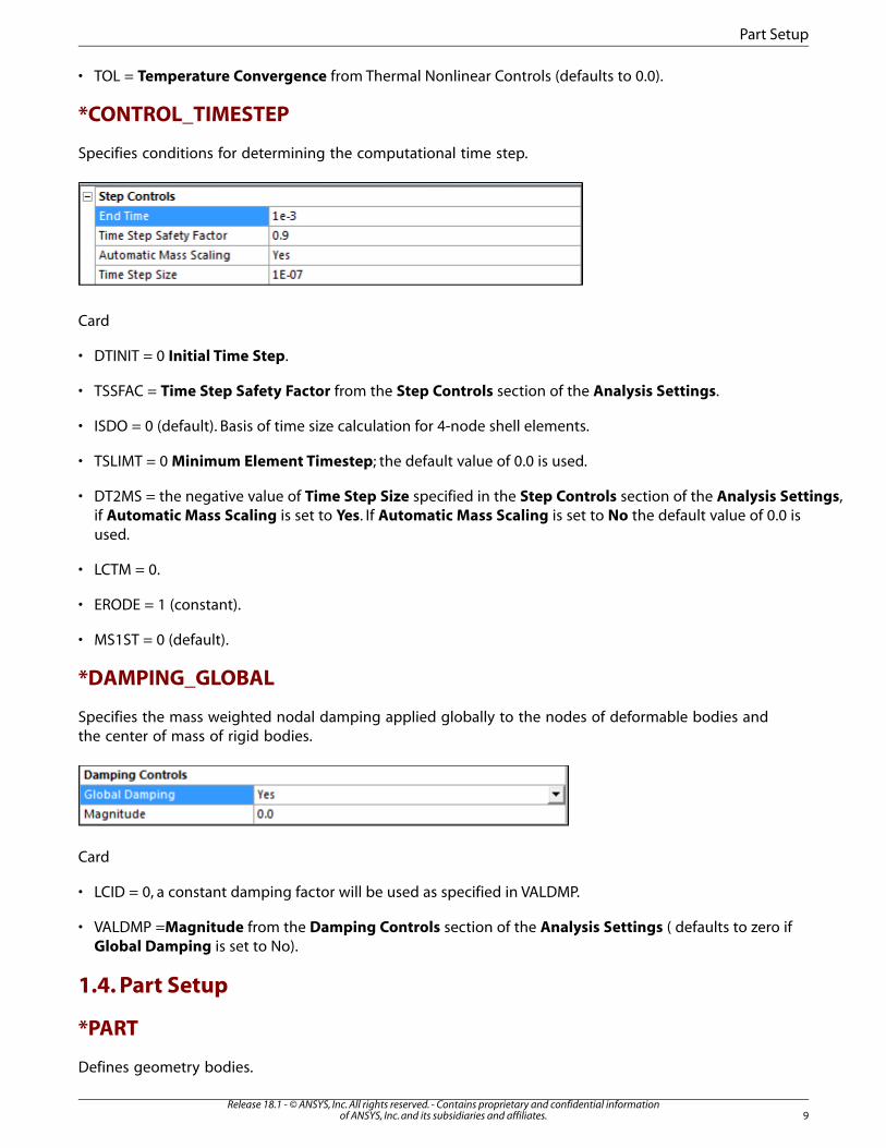
*CONTROL_TIMESTEP
Specifies conditions for determining the computational time step.
Card
• DTINIT = 0 Initial Time Step.
• TSSFAC = Time Step Safety Factor from the Step Controls section of the Analysis Settings.
• ISDO = 0 (default). Basis of time size calculation for 4-node shell elements.
• TSLIMT = 0 Minimum Element Timestep; the default value of 0.0 is used.
• DT2MS = the negative value of Time Step Size specified in the Step Controls section of the Analysis Settings,if Automatic Mass Scaling is set to Yes. If Automatic Mass Scaling is set to No the default value of 0.0 isused.
• LCTM = 0.
• ERODE = 1 (constant).
• MS1ST = 0 (default).
*DAMPING_GLOBAL
Specifies the mass weighted nodal damping applied globally to the nodes of deformable bodies andthe center of mass of rigid bodies.
Card
• LCID = 0, a constant damping factor will be used as specified in VALDMP.
• VALDMP =Magnitude from the Damping Controls section of the Analysis Settings ( defaults to zero ifGlobal Damping is set to No).
1.4. Part Setup
*PART
Defines geometry bodies.
9Release 18.1 - © ANSYS, Inc. All rights reserved. - Contains proprietary and confidential information
of ANSYS, Inc. and its subsidiaries and affiliates.
Part Setup

Card1
• HEADING = name of the body specified in the Workbench environment.
Card2
• PID = ID of the part. It is set in the LS-DYNA solver and does not reflect the ID specified in the mesh definitionof the model.
• SECID = ID of the section keyword associated with the part (see *SECTION).
• MID = ID of the material keyword associated with the part (see *MAT).
• EOSID = ID of the equation of state associated with the material of this part (*EOS and *MAT). If there is noEOS keyword associated with this part then this parameter is set to 0.
• HGID = ID of the hourglass keyword associated with the part (see *HOURGLASS). If there is no hourglasskeyword associated with this part then this parameter is set to 0.
*SECTION_BEAM
Defines cross sectional properties for beam, truss, spot weld and cable elements.
Card1
• SECID = ID of the section.
• ELFORM = 1 or 2 (default). ELFORM = 2 is set for user defined cross sections. The default element formulationoption can be changed by using the Section Object of Workbench LS-DYNA Toolbar Part/Section.
• SHRF = 0.833 (default).
• QR = 0, which LS-DYNA defaults to 2, quadrature rule is 2x2 Gauss. If the cross sectional area of the beam iscomplex or user-defined, this parameter becomes IRID and is assigned the negative value of the IRID para-meter in the corresponding *INTEGRATION_BEAM keyword (see above for details).
• CST = 2 for solid cross sections nand hollow cross sections (arbitrary user defined integration rule).
Card2
• for solid types or hollow cylinders
– TS1 = width of beam. This refers specifically to the dimension at node 1.
– TS2 = TS1. This refers specifically to the dimension at node 2.
– TT1 = 1. Height of beam. This refers specifically to the dimension at node 1. Set to zero for circular solids.
– TT2 = TT1. This refers specifically to the dimension at node 2. Set to zero for circular solids. These parametersare overwritten by the *INTEGRATION_BEAM defined for these types.
• for general symmetric types
– A = cross-sectional area.
– ISS = Iyy, moment of inertia about the local s-axis.
Release 18.1 - © ANSYS, Inc. All rights reserved. - Contains proprietary and confidential informationof ANSYS, Inc. and its subsidiaries and affiliates.10
Supported LS-DYNA Keywords

– ITT = Izz, moment of inertia about the local t-axis.
– IST = Iyz.
– J = Ixx.
The use of the Section object of the Workbench LS-DYNA toolbar Part/Section allows you to modifythe default generated values.
In presence of line Bodies:
• ELFORM = LS-DYNA ID from the Definition section of the Section object. This field is read only; the actualvalue of the element formulation is set by the Formulation section of the Section object.
If the formulation is one of the following, the Card is calculated similarly to the above definition for*SECTION_BEAM, and an *INTEGRATION_BEAM is written:
• Hughes -Liu with cross section integration
• Integrated warped beam
• Belytschko Schwer full cross-section integration
• Belytschko Schwer tubular beam with cross-section integration
If the formulation is one of the following:
• Belytschko Schwer resultant beam (resultant)
• Truss (resultant)
• Belytschko Schwer full cross-section integration
Card 2 is modified and uses the syntax for the alternative form for formulations 2, 3, and 12.
• STYPE is calculated from the section type defined in ANSYS DesignModeler or SpaceClaim.
• D1 - D6 are calculated from the dimensions defined in ANSYS DesignModeler.
If the formulation is Discrete/ Beam Cable, an additional panel is available:
11Release 18.1 - © ANSYS, Inc. All rights reserved. - Contains proprietary and confidential information
of ANSYS, Inc. and its subsidiaries and affiliates.
Part Setup

Figure 1.1: Discrete and Cable Controls when the Option is set to Discrete Beam
A material Card (*MAT_LINEAR_ELASTIC_DISCRETE_BEAM) is added to allow definition of properties forthe discrete Beam.
*MAT_LINEAR_ELASTIC_DISCRETE_BEAM
This card replaces the material defined in Engineering and its properties are calculated from it and theabove panel.
• MID = ID of material type, must be unique between the material keyword definitions.
• RO = Density of the Material
• TKR = Longitudinal Stiffness X from Discrete and Cable Controls
• TKS = Longitudinal Stiffness Y from Discrete and Cable Controls
• TKT = Longitudinal Stiffness Z from Discrete and Cable Controls
• RKR = Torsional Stiffness X from Discrete and Cable Controls
• RKS = Torsional Stiffness X from Discrete and Cable Controls
• RKT = Torsional Stiffness X from Discrete and Cable Controls
Figure 1.2: Discrete and Cable Controls when the Option is set to Cable
Release 18.1 - © ANSYS, Inc. All rights reserved. - Contains proprietary and confidential informationof ANSYS, Inc. and its subsidiaries and affiliates.12
Supported LS-DYNA Keywords

*MAT_CABLE_DISCRETE_BEAM
This card replaces the material defined in Engineering Data and its properties are calculated from it,and the above panel.
• MID = ID of material type, must be unique between the material keyword definitions.
• RO = Density of the Material
• E = Young Modulus of the Material
A material Card (*MAT_CABLE_DISCRETE_BEAM) is added to allow definition of properties for the discreteBeam.
*SECTION_SHELL
Defines section properties for shell elements.
Card1
• SECID = ID of the section.
• ELFORM = 2 (default).
• SHRF = 0.8333 (default).
• NIP = 3 (default).
Card2
• T1 = thickness of body.
• T2-T4 = T1, shell thickness at nodes 2, 3 and 4.
The use of the Section object of the Workbench LS-DYNA toolbar Part/Section allows you to modifythe default generated values.
In the presence of Surface Bodies:
• ELFORM = LS-DYNA IDfrom the Definition section of the Section object. This field is read only; the actualvalue of the element formulation is set by the Formulation section of the Section object.
• NIP = Through Thickness Integration Points from the Definition section of the Section object.
13Release 18.1 - © ANSYS, Inc. All rights reserved. - Contains proprietary and confidential information
of ANSYS, Inc. and its subsidiaries and affiliates.
Part Setup

*SECTION_SOLID
Defines section properties for solid elements.
Card
• SECID = ID of the section.
• ELFORM =
– 1 (default). Also, used for first-order hexahedral elements, 5-noded pyramids, 6-noded wedges or bodieswith mixed element types that include tetrahedrons together with hexahedrons, pyramids, or wedges.
– 10 if elements are first-order tetrahedrons.
– 16 if the elements are second-order tetrahedrons.
The use of the Section object of the Workbench LS-DYNA toolbar Part/Section allows you to modifythe default generated values.
In the presence of Solid Bodies:
• ELFORM = LS-DYNA IDfrom the Definition section of the Section object. This field is read only; the actualvalue of the element formulation is set by the Formulation section of the Section object.
*SECTION_SOLID_ALE
This keyword is written when you use the Section object of the Workbench LS-DYNA toolbarPart/Section, which allows you to modify the default generated values for the *SECTION keyword. Ifthe ALE section from the Definition of the Section object is set to Yes.
Release 18.1 - © ANSYS, Inc. All rights reserved. - Contains proprietary and confidential informationof ANSYS, Inc. and its subsidiaries and affiliates.14
Supported LS-DYNA Keywords

• ELFORM = LS-DYNA ID from the Definition section of the Section object. This field is read only; the actualvalue of the element formulation is set by the Formulation section of the Section object. If LS-DYNA ID iszero, ELFORM is set to 5 (1 Point ALE ).
Available Formulations are the following :
• 1 point ALE : ELFORM = 5
• 1 point Eulerian : ELFORM = 6
• 1 point Eulerian ambient : ELFORM = 7
• 1 point ALE Multi-Material Element : ELFORM = 11
• 1 point Integration with single material and void : ELFORM = 12
Card 2
• AFAC = Simple Average from the ALE Controls of the Section object. Smoothing weight factor - Simpleaverage.
• BFAC = Volume Weighting from the ALE Controls of the Section object. Smoothing weight factor - VolumeWeighting
• CFAC = Isoparametric Weighting from the ALE Controls of the Section object.
• DFAC = Equipotential Weighting from the ALE Controls of the Section object
• AAFAC = Advection Factor from the ALE Controls of the Section object
• START = start from the ALE Time Controls of the Section object.
• END = end from the ALE Time Controls of the Section object.
*HOURGLASS
Defines hourglass and bulk viscosity properties that are referenced in the *PART keyword via its HGIDparameter (see *PART keyword).
This keyword can be written using the Section object of the Workbench LS-DYNA toolbar objectPart/Hourglass Control, which allows you to specify body scoped hourglass definition.
15Release 18.1 - © ANSYS, Inc. All rights reserved. - Contains proprietary and confidential information
of ANSYS, Inc. and its subsidiaries and affiliates.
Part Setup

• HGID = ID of the part. It is set in the LS-DYNA solver and does not reflect the ID specified in the meshdefinition of the model.
• IHQ = Hourglass Control Type.
• QM = Hourglass from the Coefficients section of the Hourglass Control object.
• Q1 = Quadratic Bulk from the Coefficients section of the Hourglass Control object.
• Q2 = Linear Bulk from the Coefficients section of the Hourglass Control object.
• IBQ = 1 Standard LS-DYNA Bulk Viscosity
This keyword can also be created using the Keyword Snippet(also, Commands objects) for the LS-DYNAsolver. To use it, insert a Keyword Snippet under a Geometry body in the Tree Outline. The programwill automatically substitute the HGID parameter in accordance with the *PART keyword of the associatedbody. All other parameters in the Keyword Snippet are transcribed literally.
If the keyword is entered in a Keyword Snippet anywhere else in the Tree Outline, it will be exportedliterally. This practice is not recommended, however, and a warning is provided in the header of KeywordSnippet objects when detected.
*CONSTRAINED_LAGRANDE_IN_SOLID
This keyword is used for reinforcements body interactions.
• SLAVE is set to the ID of the component containing line bodies
• Master is set to the ID of the component containing solid bodies
*CONSTRAINED_RIGID_BODIES
Specifies rigid bodies to be merged into one part. The resulting Part ID matches the ID of the rigid bodydesignated as the master.
By constraining the rigid bodies together using a single multibody part you avoid specifying conflictingmotion on the nodes shared among the rigid bodies. All boundary conditions applied to the masterbody will also be applied to all the slave bodies as well. Any boundary conditions that were applied tothe slaves will be ignored.
The object Master Rigid Body allows you to specify the master rigid body.
Card
• PIDM = ID of the master rigid body.
• PIDS = ID of the slave rigid body.
1.5. Engineering Data Materials and Equations of State
Equation of State (EOS) Keywords
The following are descriptions for *EOS keywords natively supported by Workbench LS-DYNA. Moregenerally, any *EOS keyword may be introduced into the export file with the help of Commands objects
Release 18.1 - © ANSYS, Inc. All rights reserved. - Contains proprietary and confidential informationof ANSYS, Inc. and its subsidiaries and affiliates.16
Supported LS-DYNA Keywords
in the Mechanical application (termed Keyword Snippet when referring to the LS-DYNA solver). To useit, insert a Keyword Snippet under a Geometry body in the Tree Outline. The program will automaticallysubstitute the EOSID parameter, in accordance with the *PART keyword of the associated body. Allother parameters in the Keyword Snippet are transcribed literally, overriding any values that wouldotherwise derive from the Engineering Data workspace.
If the *EOS keyword is entered in a Keyword Snippet anywhere else in the Tree Outline, it will be ex-ported literally and the Engineering Data EOS information will also be exported, if present. This practiceis not recommended, however, and a warning is provided in the header of Keyword Snippet objectswhen detected.
*EOS_GRUNEISEN
Specifies a shock equation of state. This keyword is created when a Shock EOS linear equation of stateis present in the properties of a material that is used in the simulation and the Johnson Cook plasticitymodel is also present. The bilinear version of this equation of state is not currently supported.
Card1
• EOSID = ID of the keyword, must be unique between the *EOS keywords.
• C = parameter C1 for a Linear Shock EOS property.
• S1 = parameter S1 for a Linear Shock EOS property.
• S2 = Parameter Quadratic S2 for a Linear Shock EOS property.
• S3 = 0.
• GAMAO = Gruneisen Coefficient for a Linear Shock EOS property.
• A = 0.
Card2 - mandatory, left blank.
*EOS_LINEAR_POLYNOMIAL
Specifies the coefficients for a linear polynomial elastic EOS. The *EOS_LINEAR_POLYNOMIAL keywordis only created when the Johnson Cook strength property is added to the material model (which requiresan EOS), but no other EOS has been specified. It is not directly available from the Engineering Dataworkspace, however.
Card1
• EOSID = ID of the keyword, must be unique between the *EOS keywords.
• C0 = 0.
• C1 = Parameter A1.
• C2 = Parameter A2.
• C3 = Parameter A3.
• C4 = Parameter A4.
17Release 18.1 - © ANSYS, Inc. All rights reserved. - Contains proprietary and confidential information
of ANSYS, Inc. and its subsidiaries and affiliates.
Engineering Data Materials and Equations of State

• C5 = Parameter A5.
• C6 = Parameter A6.
Card2 - mandatory, left blank.
Materials keywords
The following are descriptions for *MAT keywords natively supported by resumed projects that usedthe Workbench LS-DYNA. More generally, any *MAT keyword may be introduced into the export filewith the help of Commands objects in the Mechanical application (termed Keyword Snippet whenreferring to the LS-DYNA solver). To use it, insert a Keyword Snippet under a Geometry body in theTree Outline. The program will automatically substitute the MID parameter in accordance with the *PARTkeyword (see below) of the associated body. All other parameters in the Keyword Snippet are transcribedliterally, overriding any values that would otherwise derive from the Engineering Data workspace.
If the *MAT keyword is entered in a Keyword Snippet anywhere else in the Tree Outline, it will be ex-ported literally and Engineering Data EOS information will also be exported, if present. This practice isnot recommended, however, and a warning is provided in the header of Keyword Snippet objectswhen detected.
*MAT_ADD_EROSION
ADD_EROSION is added to a given material when a failure model is defined in Engineering Data, to amaterial that doesn't support the defined failure model
Card
• MID = ID of material for which this failure model applies.
• SIGP1 = Principal Stress Failure, if present. Otherwise it is 0.
• MXEPS = Maximum Principal Strain, if present. Otherwise it is 0.
• EPSSH = Maximum Shear Strain, if present. Otherwise it is 0.
• EFFEPS = Maximum Equivalent Plastic Strain EPS, if present. Otherwise it is 0.
• MNPRES = Maximum Tensile Pressure, if present. Otherwise it is 0.
*MAT_ARRUDA_BOYCE_RUBBER (or *MAT_127)
• MID = ID of material type. Must be unique between the material keyword definitions.
• RO = density of the material from the Engineering Data workspace.
• K = Bulk modulus of the material, calculated from incompressibility parameter.
• G = Initial shear modulus of the material from the Engineering Data workspace.
Release 18.1 - © ANSYS, Inc. All rights reserved. - Contains proprietary and confidential informationof ANSYS, Inc. and its subsidiaries and affiliates.18
Supported LS-DYNA Keywords

*MAT_ELASTIC (or *MAT_001)
Specifies isotropic elastic materials. It is available for beam, shell and solid elements. This keyword isused if the selected material includes the Isotropic Elasticity strength model and the Stiffness Behavioris set to Deformable in the Definition section of the body.
Card
• MID = ID of material type. Must be unique between the material keyword definitions.
• RO = density of the material from the Engineering Data workspace.
• E = Young's modulus of the material from the Engineering Data workspace, either specified directly or cal-culated from Bulk and Shear moduli.
• PR = Poisson's ratio of the material from the Engineering Data workspace, either specified directly or calculatedfrom Bulk and Shear moduli.
*MAT_ENHANCED_COMPOSITE_DAMAGE (or *MAT_054)
Card1
• MID = ID of material type, must be unique between the material keyword definitions.
• RO = density of material.
• EA = Young's Modulus X direction from the Orthotropic Elasticity model.
• EB = Young's Modulus Y direction from the Orthotropic Elasticity model.
• EC = Young's Modulus Z direction from the Orthotropic Elasticity model.
• PRBA = Poisson's Ratio XY from the Orthotropic Elasticity model multiplied by Young's Modulus Y / Young'sModulus X.
• PRCA = Poisson's Ratio YZ from the Orthotropic Elasticity model multiplied by Young's Modulus Z / Young'sModulus X.
• PRCB = Poisson's Ratio XZ from the Orthotropic Elasticity model multiplied by Young's Modulus Z / Young'sModulus Y.
Card2
• GAB = Shear Modulus XY from the Orthotropic Elasticity model.
• GBC = Shear Modulus YZ from the Orthotropic Elasticity model.
• GCA = Shear Modulus XZ from the Orthotropic Elasticity model.
• AOPT =
– 0 (default). When this parameter is set to zero the locally orthotropic material axes are determined fromthree element nodes. The first node specifies the local origin, the second specifies one of the axes andthe third specifies the plane on which the axis rests.
– - ID of local coordinate system assigned to the body with this material model.
19Release 18.1 - © ANSYS, Inc. All rights reserved. - Contains proprietary and confidential information
of ANSYS, Inc. and its subsidiaries and affiliates.
Engineering Data Materials and Equations of State

Card 3 is left blank
Card 4 is left blank
Card 5 is left blank
Card 6
• XC = Compressive X of the Orthotropic Stress Limits definition, if present. Otherwise it is 0.
• XT = Tensile X of the Orthotropic Stress Limits definition, if present. Otherwise it is 0.
• YC = Compressive Y of the Orthotropic Stress Limits definition, if present. Otherwise it is 0.
• YT = Tensile Y of the Orthotropic Stress Limits definition, if present. Otherwise it is 0.
• SC = Shear XY of the Orthotropic Stress Limits definition, if present. Otherwise it is 0.
*MAT_HYPERELASTIC_RUBBER (or *MAT_077_H)
Specifies a general hyperelastic rubber model, optionally combined with viscoelasticity. This keywordis used if the material includes the Mooney-Rivlin, Polynomial or Yeoh hyperelastic strength model andthe Stiffness Behavior is set to Deformable in the Definition section of the body.
Card1
• MID = ID of material type, must be unique between the material keyword definitions.
• RO = density of the material from the Engineering Data workspace.
• PR = Poisson's ratio of the material from the Engineering Data workspace. Values higher than 0.49 are re-commended. Smaller values may not work and should not be used.
• N = 0, specifies that the constants in card 2 will be defined.
• NV = 0. This parameter is not used if N = 0 above.
• G = Shear modulus of the material from the Engineering Data workspace.
• SIGF = 0. This parameter is not used if N = 0 above.
Card2
• C10 = constant C10 from the Engineering Data workspace.
• C01 = constant C01 from the material properties in the Engineering Data. Set to zero for Yeoh models.
• C11 = constant C11 from the Engineering Data workspace. Set to zero for Yeoh models.
• C20 = constant C20 from the Engineering Data workspace.
• C02 = constant C02 from the Engineering Data workspace. Set to zero for Yeoh models.
• C30 = constant C30 from the Engineering Data workspace.
Release 18.1 - © ANSYS, Inc. All rights reserved. - Contains proprietary and confidential informationof ANSYS, Inc. and its subsidiaries and affiliates.20
Supported LS-DYNA Keywords

*MAT_JOHNSON_COOK (or *MAT_015)
Defines a Johnson - Cook type of material. Such materials are useful for problems with large variationsin strain rates where adiabatic temperature increases due to plastic heating cause material softening.This keyword is used if the material specified includes a Johnson Cook strength model.
Card1
• MID = ID of material type, must be unique between the material keyword definitions.
• RO = density of material.
• G = Shear modulus of material.
• E = Young's modulus of the material (shell elements only).
• PR = Poisson's ratio of the material (shell elements only).
Card2
• A = Initial yield stress from the Johnson Cook strength parameters.
• B = Hardening Constant from the Johnson Cook strength parameters.
• N = Hardening Exponent from the Johnson Cook strength parameters.
• C = Strain Rate Constant from the Johnson Cook strength parameters.
• M = Thermal Softening Exponent from the Johnson Cook strength parameters.
• TM = Melting Temperature from the Johnson Cook strength parameters.
• TR = 15, room temperature.
• EPSO = Reference Strain Rate from the Johnson Cook strength parameters.
Card3
• CP = Specific Heat from the material properties.
• PC = 0 (LS-DYNA default).
• SPALL = 2.0 (LS-DYNA default).
• IT = 0 (LS-DYNA default).
• D1 = D1 parameter of the Johnson Cook failure model definition, if present. Otherwise it is 0.
• D2 = D2 parameter of the Johnson Cook failure model definition, if present. Otherwise it is 0.
• D3 = D3 parameter of the Johnson Cook failure model definition, if present. Otherwise it is 0.
• D4 = D4 parameter of the Johnson Cook failure model definition, if present. Otherwise it is 0.
Card4
• D5 = D5 parameter of the Johnson Cook failure model definition, if present. Otherwise it is 0.
21Release 18.1 - © ANSYS, Inc. All rights reserved. - Contains proprietary and confidential information
of ANSYS, Inc. and its subsidiaries and affiliates.
Engineering Data Materials and Equations of State

• C2/P = "Reference Strain Rate (/sec)" parameter of the Johnson Cook failure model definition, if present.Otherwise it is 0.
*MAT_OGDEN_RUBBER (or *MAT_077_O)
Specifies the Ogden rubber model, optionally combined with viscoelasticity. This keyword is used if thematerial includes the Ogden hyperelastic strength model and the Stiffness Behavior is set to Deformablein the Definition section of the body.
For card 1 see *MAT_HYPERELASTIC_RUBBER
Card2
• MU1 = Material Constant MU1 from the Ogden model.
• MU2 = Material Constant MU2 from the Ogden model.
• MU3 = Material Constant MU3 from the Ogden model.
• MU4 = 0.
• MU5 = 0.
• MU6 = 0.
• MU7 = 0.
• MU8 = 0.
Card3
• ALPHA1 = Material Constant A1 from the Ogden model.
• ALPHA2 = Material Constant A2 from the Ogden model.
• ALPHA3 = Material Constant A3 from the Ogden model.
• ALPHA1 = 0.
• ALPHA1 = 0.
• ALPHA1 = 0.
• ALPHA1 = 0.
• ALPHA8 = 0.
*MAT_ORTHOTROPIC_ELASTIC (or *MAT_002)
Specifies the model for an elastic-orthotropic behavior of solids, shells, and thick shells. This keywordis created when the Orthotropic Elasticity property is present in a material that is used. The Poisson'sratios required with this keyword must be in their minor version, however Workbench requires theirmajor versions hence they are converted by multiplying them by the relevant Young's modulus ratios.
Card1
Release 18.1 - © ANSYS, Inc. All rights reserved. - Contains proprietary and confidential informationof ANSYS, Inc. and its subsidiaries and affiliates.22
Supported LS-DYNA Keywords

• MID = ID of material type, must be unique between the material keyword definitions.
• RO = density of material.
• EA = Young's Modulus X direction from the Orthotropic Elasticity model.
• EB = Young's Modulus Y direction from the Orthotropic Elasticity model.
• EC = Young's Modulus Z direction from the Orthotropic Elasticity model.
• PRBA = Poisson's Ratio XY from the Orthotropic Elasticity model multiplied by Young's Modulus Y / Young'sModulus X.
• PRCA = Poisson's Ratio YZ from the Orthotropic Elasticity model multiplied by Young's Modulus Z / Young'sModulus X.
• PRCB = Poisson's Ratio XZ from the Orthotropic Elasticity model multiplied by Young's Modulus Z / Young'sModulus Y.
Card2
• GAB = Shear Modulus XY from the Orthotropic Elasticity model.
• GBC = Shear Modulus YZ from the Orthotropic Elasticity model.
• GCA = Shear Modulus XZ from the Orthotropic Elasticity model.
• AOPT =
– 0 (default). When this parameter is set to zero the locally orthotropic material axes are determined fromthree element nodes. The first node specifies the local origin, the second specifies one of the axes andthe third specifies the plane on which the axis rests.
– - ID of local coordinate system assigned to the body with this material model.
Card3 - mandatory, left blank.
Card4 - mandatory, left blank.
*MAT_PIECEWISE_LINEAR_PLASTICITY (or *MAT_24)
Defines elasto-plastic materials with arbitrary stress-strain curve and arbitrary strain rate dependency.This keyword is used if the material specified includes a Multilinear Isotropic Hardening (BISO or MISO)strength model.
Card1
• MID = ID of material type, must be unique between the material keyword definitions.
• RO = density of material.
• E = Young's modulus of the material.
• PR = Poisson's ratio of the material.
• SIGY = Yield Strength from the BISO strength model. It is not required for MISO models.
23Release 18.1 - © ANSYS, Inc. All rights reserved. - Contains proprietary and confidential information
of ANSYS, Inc. and its subsidiaries and affiliates.
Engineering Data Materials and Equations of State

• ETAN = Tangent Modulus from the BISO strength model. It is not required for MISO models.
• FAIL = Maximum Equivalent Plastic Strain EPS parameter of the Plastic Strain failure model, if present.Otherwise it is set to 10E+20.
Card2
• C = 0.
• P = 0.
• LCSS = ID of the curve that defining effective stress versus effective plastic strain.
Card3 - mandatory, left blank.
Card4 - mandatory, left blank.
*MAT_PLASTIC_KINEMATIC (or *MAT_003)
Specifies isotropic and kinematic hardening plastic behavior in materials. This keyword is created whenthe Bilinear Kinematic Hardening (BKIN) strength model is present in a material.
Card1
• MID = ID of material type, must be unique between the material keyword definitions.
• RO = density of material.
• E = Young's modulus of the material.
• PR = Poisson's ratio of the material.
• SIGY = Yield Strength from the BKIN strength model.
• ETAN = Tangent Modulus from the BKIN strength model.
• BETA = 0.
Card2
• SRC = left blank.
• SRP = left blank.
• FS = Maximum Equivalent Plastic Strain EPS parameter of the Plastic Strain failure model, if present.Otherwise it is left blank.
*MAT_RIGID (or *MAT_020)
Specifies materials for rigid bodies. This keyword is created when the Stiffness Behavior is set to Rigidunder the Definition section of the body. Any strength or EOS material properties defined are ignored.
Card1
• MID = ID of material type, must be unique between the material keyword definitions.
Release 18.1 - © ANSYS, Inc. All rights reserved. - Contains proprietary and confidential informationof ANSYS, Inc. and its subsidiaries and affiliates.24
Supported LS-DYNA Keywords

• RO = density of material.
• E = Young's modulus of the material.
• PR = Poisson's ratio of the material.
Card2
• CMO =
– 0 if there are no constraints on the rigid body.
– -1 if rigid body is constrained in any way.
• CON1 =
– 0 if there are no constraints on the rigid body.
– = Local Coordinate System ID if associated with the constraint. Otherwise it is set to 0.
• CON2 =
– 0 if there are no constraints on the rigid body.
– = 111111 if the body is constrained with a fixed support or with a combination of a simple support anda fixed rotation.
– = 111000 if the body is constrained with a simple support.
– = 000111 if the body is constrained with a fixed rotation.
Card3
• LCO = CON1 if non-zero. Otherwise it will remain blank.
*MAT_SIMPLIFIED_JOHNSON_COOK (or *MAT_098)
Defines a Johnson - Cook type of material. Such materials are useful for problems with large variationsin strain rates where adiabatic temperature increases due to plastic heating cause material softening.This keyword is used if the material specified includes a Johnson Cook strength model without anEquation Of State.
Card1
• MID = ID of material type, must be unique between the material keyword definitions.
• RO = density of material.
• E = Young's modulus of the material.
• PR = Poisson's ratio of the material.
Card2
• A= Initial yield stress from the Johnson Cook strength parameters.
25Release 18.1 - © ANSYS, Inc. All rights reserved. - Contains proprietary and confidential information
of ANSYS, Inc. and its subsidiaries and affiliates.
Engineering Data Materials and Equations of State

• B = Hardening Constant from the Johnson Cook strength parameters.
• N = Hardening Exponent from the Johnson Cook strength parameters.
• C = Strain Rate Constant from the Johnson Cook strength parameters.
• PSFAIL = Maximum Equivalent Plastic Strain EPS parameter of the Plastic Strain failure model, if present.Otherwise it is set to 10E+20.
• SIGMAX = 0. Not used.
• SIGSAT = 0. Not used.
• EPSO = Reference Strain Rate from the Johnson Cook strength parameters.
1.6. Mesh Definition
*NODE
Defines nodes. All the parameters are obtained from mesh definitions of the model.
Card
• NID = ID of the node.
• X = x coordinate.
• Y = y coordinate.
• Z = z coordinate.
*ELEMENT_BEAM
Specifies beam elements.
Card
• EID = ID of the element.
• PID = ID of the part it belongs to.
• N1 = ID of nodal point 1.
• N2 = ID of nodal point 2.
• N3 = ID of nodal point 3, used for cross section orientation.
*ELEMENT_SHELL
Specifies three, four, six and eight noded shell elements.
Card
• EID = ID of the element.
Release 18.1 - © ANSYS, Inc. All rights reserved. - Contains proprietary and confidential informationof ANSYS, Inc. and its subsidiaries and affiliates.26
Supported LS-DYNA Keywords

• PID = ID of the part it belongs to.
• N1 = ID of nodal point 1.
• N2 = ID of nodal point 2.
• N3 = ID of nodal point 3.
• N4 = ID of nodal point 4.
• N5-8 = ID of mid side nodes for six and eight noded shells.
*ELEMENT_SHELL_THICKNESS_OFFSET
Surface body thicknesses properties can be defined on faces of surface bodies using the Thicknessobject in the Geometry. This keyword defines scoped surface body thickness.
Card1 - the same as *ELEMENT_SHELL
Card2
• THIC1 = Thickness field of the Thickness object.
• THIC2 = Thickness field of the Thickness object.
• THIC3 = Thickness field of the Thickness object.
• THIC4 =Thickness field of the Thickness object.
Card3
• OFFSET = value calculated from the Offset Type field
of the Thickness object. if Offset Type =
– Middle, it equals zero.
– Top, it is equal to half of the thickness as a negative number.
– Bottom, it is equal to half of the thickness.
– User defined, it is equal to the value defined in the field Membrane offset.
27Release 18.1 - © ANSYS, Inc. All rights reserved. - Contains proprietary and confidential information
of ANSYS, Inc. and its subsidiaries and affiliates.
Mesh Definition

*ELEMENT_SHELL_OFFSET_COMPOSITE
Layered section properties can be defined on faces of surface bodies using the Layered Section objectin the Geometry. This keyword defines layered section thickness.
Card1 - the same as *ELEMENT_SHELL
Card2
• OFFSET = value calculated from the Offset Type field
of the Layered Section object. if Offset Type =
– Middle, it equals zero.
– Top, it is equal to half of the thickness as a negative number.
– Bottom, it is equal to half of the thickness.
– User defined, it is equal to the value defined in the field Membrane offset.
Card3
Defines the property of two layers. Card3 is repeated as many times as required to specify all the layersin the section. The sequence is starting with the bottommost layer.
• MID1= ID of material in Layer1. Must be unique between the material keyword definitions.
• THICK1 = Thickness of the Layer1.
• B1 = Angle defined in the worksheet for Layer1 projected onto the element surface.
• MID2 = ID of material in Layer 2. Must be unique between the material keyword definitions.
• THICK2 = Thickness of the Layer2
• B2 = Angle defined in the worksheet for Layer2 projected onto the element surface.
*ELEMENT_SOLID
Specifies 3D solid elements including 10-noded tetrahedrons (second order). Apart from the secondorder case the two cards are combined into one.
Release 18.1 - © ANSYS, Inc. All rights reserved. - Contains proprietary and confidential informationof ANSYS, Inc. and its subsidiaries and affiliates.28
Supported LS-DYNA Keywords

Card1
• EID = ID of the element.
• PID = ID of the part it belongs to.
Card2
• N1 = ID of nodal point 1.
• N2 = ID of nodal point 2.
• N3 = ID of nodal point 3.
• N4 = ID of nodal point 4.
• .
• .
• .
• N10 = ID of nodal point 10.
1.7. Coordinate Systems
*DEFINE_COORDINATE_SYSTEM
Specifies a local coordinate system with three points: one at the local origin, one on the local x-axisand one on the local x-y plane.
Card1
• CID = ID of the coordinate system, must be unique.
• XO = global X-coordinate of the origin.
• YO = global Y-coordinate of the origin.
• ZO = global Z-coordinate of the origin.
• XL = global X-coordinate of a point on the local x-axis.
• YL = global Y-coordinate of a point on the local x-axis.
• ZL = global Z-coordinate of a point on the local x-axis.
Card2
• XP = global X-coordinate of a point on the local x-y plane.
• YP = global Y-coordinate of a point on the local x-y plane.
• ZP = global Z-coordinate of a point on the local x-y plane.
29Release 18.1 - © ANSYS, Inc. All rights reserved. - Contains proprietary and confidential information
of ANSYS, Inc. and its subsidiaries and affiliates.
Coordinate Systems

*DEFINE_VECTOR
Specifies a vector by defining the coordinates of two points. This keyword defines the local coordinatesystem with respect to which a *BOUNDARY_PRESCRIBED_MOTION is prescribed. The ID of this coordinatesystem is specified with parameter CID.
Card
• VID = ID of the vector.
• XT = 0, the local x-coordinate of the origin of the coordinate system specified with CID below.
• YT = 0, the local y-coordinate of the origin of the coordinate system specified with CID below.
• ZT = 0, the local z-coordinate of the origin of the coordinate system specified with CID below.
• XH = 1 if the vector has a component in the x direction of the coordinate system specified with CID. Otherwise,this is set to 0.
• YH = 1 if the vector has a component in the x direction of the coordinate system specified with CID. Otherwise,this is set to 0.
• ZH = 1 if the vector has a component in the x direction of the coordinate system specified with CID. Otherwise,this is set to 0.
• CID = ID of the coordinate system used to define the vector. If no coordinate system is specified this para-meter is set to 0 to specify the global coordinate system.
1.8. Components and Named Selections
*SET_NODE_LIST
Defines a set of nodes. Card2 is repeated as many times as required to specify all the node IDs in theset.
Card1
• SID = ID of the set.
Card2
• NID1-NID8 = IDs for eight of the nodes in the set.
*SET_PART_LIST
Defines a set of parts. Card2 is repeated as many times as required to specify all the part IDs in the set.
Card1
• SID = ID of the set.
Card2
• PID1-PID8 = IDs for eight of the parts in the set.
Release 18.1 - © ANSYS, Inc. All rights reserved. - Contains proprietary and confidential informationof ANSYS, Inc. and its subsidiaries and affiliates.30
Supported LS-DYNA Keywords

*SET_SEGMENT
Defines triangular and quadrilateral segments. Card2 is repeated as many times as required to specifyall the segments in the set.
Card1
• SID = ID of the set.
Card2
• N1-N4 = IDs of nodes that define one of the segments. For triangular segments N4=N3.
1.9. Remote Points and Point Masses
*CONSTRAINED_NODAL_RIGID_BODY
this keyword is generated for remote points. Remote points are a way of abstracting a connection toa solid model, be it a vertex, edge, face, body, or node, to a point in space (specified by Location).
Remote Points are akin to the various remote loads available in the Mechanical application. Remoteboundary conditions create remote points in space behind the scenes, or, internally, whereas the RemotePoint objects define a specific point in space only. Remote point is converted to a rigid constraint (nodal rigid body), independently of the stiffness behavior.
the location set in the Remote Point Scope is not used in the input file definition.
Card1
31Release 18.1 - © ANSYS, Inc. All rights reserved. - Contains proprietary and confidential information
of ANSYS, Inc. and its subsidiaries and affiliates.
Remote Points and Point Masses

• PID = ID of the Rigid Body. It is set in the LS-DYNA solver and does not reflect the ID specified in the remotepoint definition.
• NSID identifies a set of nodes that are to be defined as a rigid body. This set of nodes is based on the scopedentities. The set consists of nodes from several different deformable parts.
• PNODE = 0. This is not used in the exported file.
• DRFLAG = the value is calculated from the translational active degrees of freedom when the DOF Selectionin the Remote Point definition is set to Manual. It allows you to deactivate certain degrees of freedom inthe rigid body definition. DRFLAG =
– 1, when X Component is inactive.
– 2, when Y Component is inactive.
– 3, When Z Component is inactive.
– 4, when X and Y Component are inactive.
– 5, when Y and Z Component are inactive.
– 6, when Z and X Component are inactive.
– 7, when X, Y, and Z Components are inactive.
• RRFLAG = the value calculated from the rotational active degrees of freedom when the DOF Selection inthe Remote Point Definition is set to Manual. It allows you to deactivate certain degrees of freedom in therigid body definition. RRFLAG =
– 1, when Rotation X is inactive.
– 2, when Rotation Y is inactive.
– 3, when Rotation Z is inactive.
– 4, when Rotation X and Y are inactive.
– 5, when Rotation Y and Z are inactive.
– 6, when Rotation Z and X are inactive.
– 7, when Rotation X, Y, and Z are inactive.
*CONSTRAINED_NODAL_RIGID_BODY_INERTIA
This keyword is generated for point masses. Point masses use a remote point for their definition, or canbe applied on a remote point. See *CONSTRAINED_NODAL_RIGID_BODY for additional information.
Card1
• PID = ID of the Rigid Body. It is set in the LS-DYNA solver and does not reflect the ID specified in the remotepoint/Point Mass definition.
• NSID identifies a set of nodes that are to be defined as a rigid body. This set of nodes is based on the scopedentities. The set consists of nodes from several different deformable parts.
Release 18.1 - © ANSYS, Inc. All rights reserved. - Contains proprietary and confidential informationof ANSYS, Inc. and its subsidiaries and affiliates.32
Supported LS-DYNA Keywords

• PNODE = 0. This is not used in the exported file.
• DRFLAG = 0. All Translational degrees of freedom are active in the rigid body definition.
• RRFLAG = 0. All Rotational degrees of freedom are active in the rigid body definition.
Card2
• XC = X Coordinate from the Scope of the Point Mass object.
• YC = Y Coordinate from the Scope of the Point Mass object.
• ZC = Z Coordinate from the Scope of the Point Mass object.
• TM = Mass from the Scope of the Point Mass object.
Card3
• IXX= Mass Moment Of Inertia X from the Definition of the Point Mass object.
• IXY = 0
• IXZ = 0
• IYY = Mass Moment Of Inertia Y from the Definition of the Point Mass object.
• IYZ = 0
• IZZ = Mass Moment Of Inertia Z from the Definition of the Point Mass object.
*INITIAL_VELOCITY_GENERATION
Specifies initial translational and rotational velocities.
Card1
• ID = ID of part where the initial velocity is applied.
• STYP = 2, the velocity is applied to a whole part. In Workbench initial velocities can only be applied to wholeparts.
• OMEGA = angular velocity about the rotational axis.
• VX = initial translational velocity in the x direction.
• VY = initial translational velocity in the y direction.
• VZ = initial translational velocity in the z direction.
• IVATN = 0 (default) slave bodies of a multibody part are not assigned the initial velocities of the master part.
• ICID = Local coordinate system ID. The specified velocities are in the local system.
Card2
• XC = 0. x coordinate of the origin of the applied coordinate system.
33Release 18.1 - © ANSYS, Inc. All rights reserved. - Contains proprietary and confidential information
of ANSYS, Inc. and its subsidiaries and affiliates.
Remote Points and Point Masses

• YC = 0. y coordinate of the origin of the applied coordinate system.
• ZC = 0. z coordinate of the origin of the applied coordinate system.
• NX = x-direction cosine.
• NY = y-direction cosine.
• NZ = z-direction cosine.
• PHASE = 0 (default), velocities are applied immediately.
• IRIGID = 0: Option to overwrite or automatically set rigid body velocities defined on the *PART_INERTIA and*CONSTRAINED_NODAL_RIGID_BODY _INERTIA cards.
*INITIAL_VELOCITY_RIGID_BODY
Specifies initial translational and rotational velocities at the center of gravity for rigid bodies.
Card
• PID = ID of the rigid body.
• VX = initial translational velocity in the x direction.
• VY = initial translational velocity in the y direction.
• VZ = initial translational velocity in the z direction.
• VXR = initial rotational velocity around the x-axis.
• VYR = initial rotational velocity around the y-axis.
• VZR = initial rotational velocity around the z-axis.
1.10. Contacts and Body Interactions
*CONTACT_AUTOMATIC_GENERAL
Specifies friction or frictionless contacts between line bodies (beams). This keyword is created if thecontact is specified using Body Interactions and the geometry contains line bodies.
All the parameter cards are the same as in *CONTACT_AUTOMATIC_SINGLE_SURFACE.
*CONTACT_AUTOMATIC_NODES_TO_SURFACE
Specifies nodes-to-surface friction or frictionless contacts. This keyword is created if the contact is specifiedusing a Contact Region and the Behavior is set to Asymmetric.
Card1 - mandatory
• SSID = ID for the set of slave nodes involved in the contact.
• MSID = ID for the set of master segments involved in the contact.
Release 18.1 - © ANSYS, Inc. All rights reserved. - Contains proprietary and confidential informationof ANSYS, Inc. and its subsidiaries and affiliates.34
Supported LS-DYNA Keywords

• SSTYP = 4, the slave entities for the contact are nodes.
• MSTYP = 0, the master entities for the contact are segments.
• SBOXID, MBOXID, SPR and MPR are the same as in *CONTACT_AUTOMATIC_SINGLE_SURFACE.
Parameter Card2 and Card3 is the same as in *CONTACT_AUTOMATIC_SINGLE_SURFACE.
*CONTACT_AUTOMATIC_SINGLE_SURFACE
Specifies friction or frictionless contacts between parts. This keyword is created if the contact is specifiedusing Body Interactions.
Card1 - mandatory
• SSID = ID for the set of parts created for the bodies in the Body Interaction. If the contact is applied to allthe bodies in the geometry then this parameter is set to 0.
• MSID = 0.
• SSTYP =2, the slave entities are parts. If the contact is applied to all the bodies in the geometry then thisparameter is set to 5.
• MSTYP = 2, the master entities are parts. If the contact is applied to all the bodies in the geometry then thisparameter is set to 0.
• SBOXID = It is not used, will be left blank.
• MBOXID = It is not used, will be left blank.
• SPR = 1 (constant) requests that forces on the slave side of the contact be included in the results files NCFORC(ASCII) and INTFOR (binary).
• MPR = 1 (constant) requests that forces on the master side of the contact be included in the results filesNCFORC (ASCII) and INTFOR (binary). T
Card2 - mandatory
• FS = Friction Coefficient value from the inputs for frictional contact.
• FD = Dynamic Coefficient value from the inputs for frictional contact.
• DC = Decay Constant value from the inputs for frictional contact.
• VC = 0 (LS-DYNA default).
• VDC = 10 (constant). This parameter specifies the percentage of the critical viscous damping coefficient tobe used in order to avoid undesirable oscillation in the contact.
Card3 - mandatory, left blank for defaults to be used.
Card A is the same as for *CONTACT_AUTOMATIC_SURFACE_TO_SURFACE.
35Release 18.1 - © ANSYS, Inc. All rights reserved. - Contains proprietary and confidential information
of ANSYS, Inc. and its subsidiaries and affiliates.
Contacts and Body Interactions

*CONTACT_AUTOMATIC_SURFACE_TO_SURFACE
Defines specific surface-to-surface friction or frictionless contacts. This keyword is created if the contactis specified using a Contact Region and the Behavior is set to Symmetric.
Card1 - mandatory
• SSID = ID for the set of slave segments involved in the contact.
• MSID = ID for the set of master segments involved in the contact.
• SSTYP = 0, the slave entities for the contact are segments.
• MSTYP = 0, the master entities for the contact are segments.
• SBOXID, MBOXID, SPR and MPR are the same as in *CONTACT_AUTOMATIC_SINGLE_SURFACE.
Parameter Card2 and Card3 are the same as in *CONTACT_AUTOMATIC_SINGLE_SURFACE.
Card A
• SOFT = 2 except for asymmetric contacts like NODES_TO_SURFACE and unbreakable bonded contacts forwhich it is set to 1.
• SOFSCL = left blank, the default value of 0.1 will be used. This scale factor is used to determine the stiffnessof the interface when SOFT is set to 1. For SOFT = 2 scale factor SLSFAC (see *CONTROL_CONTACT) is usedinstead.
• LCIDAB = left blank.
• MAXPAR= left blank.
• SBOPT = 3.
• DEPTH = 5.
*CONTACT_AUTOMATIC_SURFACE_TO_SURFACE_TIEBREAK
Specifies breakable symmetric bonded contacts. This keyword is created for Bonded contact when theBreakable option is set to Stress Criteria and the contact Behavior is set to Symmetric.
Card 1 is the same as in *CONTACT_TIED_SURFACE_TO_SURFACE_OFFSET.
Card2 - mandatory
• FS = Normal Stress Limit value for the bonded contact.
• FD = Shear Stress Limit value for the bonded contact.
• DC = 0 (LS-DYNA default). This parameter is not required for bonded contacts.
• VC and VDC are the same as in *CONTACT_AUTOMATIC_SINGLE_SURFACE.
Card3 - mandatory, is left blank.
Card A is the same as for *CONTACT_AUTOMATIC_SURFACE_TO_SURFACE.
Release 18.1 - © ANSYS, Inc. All rights reserved. - Contains proprietary and confidential informationof ANSYS, Inc. and its subsidiaries and affiliates.36
Supported LS-DYNA Keywords

*CONTACT_ONEWAY_AUTOMATIC_SURFACE_TO_SURFACE_TIEBREAK
Specifies breakable asymmetric bonded contacts. This keyword is created for Bonded contact whenthe Breakable option is set to Stress Criteria and the contact Behavior is set to Asymmetric.
Parameter cards are the same as in *CONTACT_AUTOMATIC_SURFACE_TO_SURFACE_TIEBREAK.
Card A is not used for this keyword.
*CONTACT_TIED_NODES_TO_SURFACE_OFFSET
Specifies non breakable asymmetric bonded contacts. This keyword is created for Bonded contacts thatare not designated as Breakable whose Behavior is set to Asymmetric. This keyword is not used forBody Interactions as these types of contacts are always symmetric.
Card1 - mandatory
• SSID = ID for the set of slave nodes involved in the contact.
• MSID = ID for the set of master segment or for the set of parts involved in the contact.
• SSTYP = 4. SSID indicates the ID for a set of nodes.
• MSTYP = 0, MSID indicates the ID for a set of segments.
• SBOXID, MBOXID, SPR and MPR are the same as in *CONTACT_AUTOMATIC_SINGLE_SURFACE.
Card 2 left blank.
Card 3
• SFS = left blank, the default value of 1.0 will be used. Default slave penalty stiffness scale factor for SLSFAC(see *CONTROL_CONTACT).
• SFM= left blank, the default value of 1.0 will be used. Default master penalty stiffness scale factor for SLSFAC(see *CONTROL_CONTACT).
• SST = the negative value of:
"Maximum Offset" is the Definition parameter available for bonded contacts and body interactions."Maximum Offset" is obtained from the inputs of the Contact Region of Bonded type.
• MST = SST.
*CONTACT_TIED_SURFACE_TO_SURFACE_OFFSET
Specifies general non-breakable bonded contacts that are symmetric. This keyword is created for Bondedand non-breakable contacts which are defined by Contact Regions that are Bonded, non-breakableand whose Behavior is set to Symmetric.
Card1 - mandatory
37Release 18.1 - © ANSYS, Inc. All rights reserved. - Contains proprietary and confidential information
of ANSYS, Inc. and its subsidiaries and affiliates.
Contacts and Body Interactions

• SSID = ID for a set of slave segments or a set of parts involved in the contact.
• MSID = ID for the set of master segments or the set of parts involved in the contact.
• SSTYP = specifies whether the ID used in SSID represents parts or segments. It is set to 0 if SSID representsa set of segments and 2 if it represents a set of parts.
• MSTYP = SSTYP.
• SBOXID, MBOXID, SPR and MPR are the same as in *CONTACT_AUTOMATIC_SINGLE_SURFACE.
Cards 2 and 3 are the same as in *CONTACT_TIED_NODES_TO_SURFACE_OFFSET.
Card A is the same as for *CONTACT_AUTOMATIC_SURFACE_TO_SURFACE.
*CONSTRAINED_SPOTWELD
Specifies spot welds between non-contiguous nodal pairs of shell elements. This keyword is createdwhen a spot weld contact is defined in the Mechanical application.
Card
• N1 = ID of the first node used in the weld.
• N2 = ID of the second node present in the weld.
• SN = Normal force at weld failure.
• SS = Shear force at weld failure.
• N = Exponent of normal force.
• M = Exponent of shear force.
1.10.1. Keywords Created from the Contact Properties Object
the use of the Contact Properties object of the Workbench LS-DYNA toolbar Part/Section allows tomodify the default generated values ( the type of the contact ) and specify additional values.
Release 18.1 - © ANSYS, Inc. All rights reserved. - Contains proprietary and confidential informationof ANSYS, Inc. and its subsidiaries and affiliates.38
Supported LS-DYNA Keywords

*CONTACT_ERODING_SINGLE_SURFACE is written if the contact is specified using a body interaction.
The following keywords are written if the contact is specified using a contact region, and the indicatedconditions exist.
*CONTACT_ERODING_NODES_TO_SURFACE is written if the contact Properties Type Section is set toEroding and the contact is asymmetric.
*CONTACT_ERODING_SURFACE_TO_SURFACE is written if the contact Properties Type Section is set toEroding and the contact is symmetric.
*CONTACT_FORMING_SURFACE_TO_SURFACE is written if the contact Properties Type Section is set toForming and the contact is asymmetric.
*CONTACT_FORMING_ONE_WAY_SURFACE_TO_SURFACE is written if the contact Properties Type Sectionis set to Forming and the contact is asymmetric.
*CONTACT_FORMING_NODES_TO_SURFACE is written if the contact Properties Type Section is set toForming and the contact is asymmetric, and the scoped entities on the slave side are edges.
The cards for these contact keywords are as follows:
Card1
• BT = Birth Time from the Common Controls section of the Contact Properties object.
• DT = Death Time from the Common Controls section of the Contact Properties object.
• SFS = Slave Penalty Scale Factor from the Common Controls section of the Contact Properties object.
• SFM = Master Penalty Scale Factor from the Common Controls section of the Contact Properties object.
• SST = Optional Thickness for Slave Surface from the Advanced Controls section of the Contact Propertiesobject.
39Release 18.1 - © ANSYS, Inc. All rights reserved. - Contains proprietary and confidential information
of ANSYS, Inc. and its subsidiaries and affiliates.
Contacts and Body Interactions

• MST = Optional Thickness for Master Surface from the Advanced Controls section of the Contact Propertiesobject.
• DEPTH = Depth from the Advanced Controls section of the Contact Properties object.
Card A is also modified
• SOFT = Soft Constraint Formulation from the Advanced Controls section of the Contact Properties object.
• SOFTSCL = Soft Constraint Scale Factor from the Advanced Controls section of the Contact Propertiesobject.
If the contact type is set to Eroding, additional parameters are available to support this formulation.
• ISYM = Symmetry Plane Option from the Erosion Controls section of the Contact Properties object.
• IADJ = Erosion Node Option from the Erosion Controls section of the Contact Properties object.
• EROSOP = Solid Elements Treatment from the Erosion Controls section of the Contact Properties object.
*CONTACT_FORCE_TRANSDUCER_PENALTY
When single surface contacts are used, one or more force transducers are added via the *CON-TACT_FORCE_TRANSDUCER_PENALTY command. A force transducer does not produce any contactforces and allows you to monitor the contact forces on a subset of parts of the models.
A force transducer is added for each body involved in a body interaction (Frictionless or Frictional).
*CONSTRAINED_LAGRANGE_IN_SOLID
1.11. Magnitude and Tabular Data
*DEFINE_CURVE
Specifies magnitudes that are given in tabular format. Some keywords require magnitudes to be specifiedas a load curve. Should a constant be needed, it may be represented as a curve by repeating its valuefor time steps 0 and 1.
Card1
• LCID = ID for load curve, is incremented every time a new load curve is defined.
Card2, 3, 4...
• A = abscissa value, usually time.
• O = ordinate (function) value.
1.12. Acceleration and Gravity
*LOAD_BODY_X
Specifies gravitational or other acceleration loads in the x direction. The load is applied to all nodes inthe model.
Release 18.1 - © ANSYS, Inc. All rights reserved. - Contains proprietary and confidential informationof ANSYS, Inc. and its subsidiaries and affiliates.40
Supported LS-DYNA Keywords

Card
• LCID = ID of the load curve that represents the magnitude of the load (see *DEFINE_CURVE).
• SF = 1.0 (default), load curve scale factor.
• LCIDDR = 0 (default), ID of load curve defined for dynamic relaxation.
• XC = 0.0 (default), X-center of rotation needed for angular velocities.
• YC = 0.0 (default), Y-center of rotation needed for angular velocities.
• ZC = 0.0 (default), Z-center of rotation needed for angular velocities.
• CID = ID of local coordinate system used. Set to 0 for the global coordinate system.
*LOAD_BODY_Y
Specifies gravitational or other acceleration loads in the y direction. The load is applied to all nodes inthe model.
Card
(see *LOAD_BODY_X).
*LOAD_BODY_Z
Specifies gravitational or other acceleration loads in the z direction. The load is applied to all nodes inthe model.
Card
(see *LOAD_BODY_X).
1.13. Supports
*BOUNDARY_SPC_SET
Specifies Fixed Support, Simple Support and Fixed Rotation constraints.
Card
• NSID = ID of set of nodes to which the boundary is applied.
• CID = ID of the associated coordinate system. 0 specifies the global coordinate system.
• DOFX = 0 or 1 for free or fixed translation, respectively, along the x direction. It is set to 0 for Fixed Rotationand to 1 otherwise.
• DOFY = 0 or 1 for free or fixed translation, respectively, along the y direction. It is set to 0 for Fixed Rotationand to 1 otherwise.
• DOFZ = 0 or 1 for free or fixed translation, respectively, along the z direction. It is set to 0 for Fixed Rotationand to 1 otherwise.
41Release 18.1 - © ANSYS, Inc. All rights reserved. - Contains proprietary and confidential information
of ANSYS, Inc. and its subsidiaries and affiliates.
Supports

• DOFRX = 0 or 1 for free or fixed translation, respectively, along the x direction. It is set to 0 for Simple Supportand to 1 otherwise.
• DOFRY = 0 or 1 for free or fixed translation, respectively, along the y direction. It is set to 0 for Simple Supportand to 1 otherwise.
• DOFRZ = 0 or 1 for free or fixed translation, respectively, along the z direction. It is set to 0 for Simple Supportand to 1 otherwise.
*BOUNDARY_PRESCRIBED_MOTION_RIGID
See *BOUNDARY_PRESCRIBED_MOTION_SET
*BOUNDARY_PRESCRIBED_MOTION_SET
Specifies velocity and displacement boundary conditions.
Card1
• ID = ID of set of nodes or part (for rigid bodies) to which the boundary condition is applied.
• DOF = 1, 2 or 3 depending on whether the boundary condition is in the x, y or z direction respectively, andis a translational boundary condition.
DOF = 4, 5 or 6 depending on whether the boundary condition is in the x, y or z direction respectively,and is a rotational boundary condition.
Setting 4 is used if the boundary is applied according to a local coordinate system.
• VAD = 0 or 2 depending whether the boundary condition is velocity or displacement.
• LCID = ID of the curve prescribing the magnitude of the boundary condition. Constant values of velocityare applied as a step function from time = 0. Constant values of displacement are ramped from zero at time= 0 to the constant value at termination time. This is done to make sure that displacements are applied ina transient fashion.
• SF = 1.0 (default) scale factor for load curve.
• VID = 0 (default). ID of vector that defines the local coordinate system the boundary condition is appliedwith.
• DEATH = 0.0 (default), sets it to 1E28.
• BIRTH = 0, the motion is applied from the beginning of the solution.
Card2: not required.
1.14. Loads
*LOAD_NODE_SET
Applies a concentrated nodal force to a set of nodes.
Card
Release 18.1 - © ANSYS, Inc. All rights reserved. - Contains proprietary and confidential informationof ANSYS, Inc. and its subsidiaries and affiliates.42
Supported LS-DYNA Keywords

• NSID = the set of nodes where the force is applied.
• DOF = 1, 2 or 3 depending on the force direction x, y or z.
• LCID = ID of the load curve that describes the magnitude of the force (see *DEFINE_CURVE).
• SF = 1.0 (default), load curve scale factor.
• CID = ID of local coordinate system used. Set to 0 for the global coordinate system.
*LOAD_RIGID_BODY
Applies a concentrated nodal force to a rigid body. The force is applied at the center of mass.
Card
See *LOAD_NODE_SET. Note that parameter NSID is replaced by PID which is the ID of the part theforce is applied to.
*LOAD_SEGMENT_SET
Applies a distributed pressure load over each segment in a segment set.
Card
• LCID = ID of the load curve that describes the magnitude of the pressure (see *DEFINE_CURVE).
• SSID = ID of set of nodes to which the pressure is applied.
• SF = 1.0 (default), load curve scale factor.
• AT = arrival time for pressure is assigned the time at load step 1 if pressure is given in tabular form or 0 ifconstant pressure.
1.15. Discrete Connections
*SECTION_DISCRETE
Defines section properties for solid elements. DRO is the Displacement/Rotation Option.
• SECID = ID of the section.
• DRO =
– 0 for translational spring/damper.
– 1 for torsional spring/damper.
*ELEMENT_DISCRETE
Specifies spring elements.
• EID = ID of the element.
• PID = ID of the part it belongs to.
43Release 18.1 - © ANSYS, Inc. All rights reserved. - Contains proprietary and confidential information
of ANSYS, Inc. and its subsidiaries and affiliates.
Discrete Connections

• N1 = ID of nodal point 1.
• N2 = ID of nodal point 2.
*MAT_SPRING_ELASTIC
This keyword is used in support of spring connections, the K parameter of this material keyword is thestiffness of the string.
• MID = ID of material type. Must be unique between the material keyword definitions.
• K = Elastic stiffness (force/displacement) or (moment/rotation).
*MAT_DAMPER_VISCOUS
This keyword is used in support of spring connections. The damping constant DC of this material is thedamping parameter of the spring, if this damping is non null.
• MID = ID of material type. Must be unique between the material keyword definitions.
• DC = Damping constant (force/displacement rate) or (moment/rotation rate).
1.16. Other Supports
*BOUNDARY_NON_REFLECTING
Specifies impedance boundaries. Impedance boundaries can only be applied on solid elements in LS-DYNA.
Card
• SSID = ID of segment on whose nodes the boundary is applied (see *SET_SEGMENT bellow).
• AD = 0.0 (default) for setting the activation flag for dilatational waves to on.
• AS = 0.0 (default) for setting the activation flag for shear waves to on.
*BOUNDARY_SLIDING_PLANE
Defines a boundary plane for sliding symmetry.
• NSID = ID of the set of nodes to which the boundary is applied
• VX = X component of vector defining normal.
• VY = Y component of vector defining normal.
• VZ = Z component of vector defining normal.
• COPT =
– 0 if the Option is set to node moves on normal plane.
– 1 if the Option is set to node moves only in vector direction.
Release 18.1 - © ANSYS, Inc. All rights reserved. - Contains proprietary and confidential informationof ANSYS, Inc. and its subsidiaries and affiliates.44
Supported LS-DYNA Keywords

*RIGID_WALL_PLANAR
The RIGIDWALL option provides a simple way of treating contact between a rigid surface and nodalpoints of a deformable body, called slave nodes.
• NSID = ID of the set of nodes to which the boundary is applied.
• XT, YT, ZT, XH, YH, ZH are calculated from the coordinate system definition; the normal Z of the coordinatesystem is the normal to the plane.
• FRIC = Friction
1.17. Environment Temperature
*INITIAL_TEMPERATURE_SET
This keyword is added in coupled structural thermal analyses, where it defines the initial temperatureof the environment.
• NSID = 0. All nodes of the model are initialized with the temperature Temp.
• Temp = temperature of the environment.
1.18. ASCII Files
The following keywords specify time-history output (ASCII format) for an explicit dynamics analysis. Thetime history files output are requested through Time History Output Controls section of the AnalysisSettings. Up to 10 ASCII files can be requested in the GUI. The sampling time is calculated from thenumber of values requested and from the end time of the simulation.
45Release 18.1 - © ANSYS, Inc. All rights reserved. - Contains proprietary and confidential information
of ANSYS, Inc. and its subsidiaries and affiliates.
ASCII Files

The results files (GLSTAT, BNDOUT, RCFORC, SPCFORC,MATSUM) are always output by Workbench LS-DYNA. The sampling frequency can, however, be modified.
*DATABASE_HISTORY_NODE_SET
Controls which nodes or elements are output into the binary history file and the ASCII file NODOUT fora particular result tracker.
Card
ID1 is set to the id of the component defined by the result tracker object.
*DATABASE_BNDOUT
Specifies the sampling parameters for the BNDOUT results file (stores Boundary condition forces andenergy).
Card
DT = End Time divided by Value from the Time History Output Controls section of the AnalysisSettings.
*DATABASE_DEFGEO
Specifies the sampling parameters for the DEFGEO results file (stores Deformed Geometry Data).
Card
DT = End Time divided by Value from the Time History Output Controls section of the AnalysisSettings.
*DATABASE_DEFORC
Specifies the sampling parameters for the DEFORC results file (Discrete Elements Data).
Card
DT = End Time divided by Value from the Time History Output Controls section of the AnalysisSettings.
*DATABASE_GCEOUT
Specifies the sampling parameters for the GCEOUT results file (Geometric Contact Entities).
Card
DT = End Time divided by Value from the Time History Output Controls section of the AnalysisSettings.
*DATABASE_GLSTAT
Specifies the sampling parameters for the GLSTAT results file (stores general energy results).
Card
Release 18.1 - © ANSYS, Inc. All rights reserved. - Contains proprietary and confidential informationof ANSYS, Inc. and its subsidiaries and affiliates.46
Supported LS-DYNA Keywords
• DT = End Time divided by Value from the Time History Output Controls section of the Analysis Settings.
*DATABASE_INTFORC
Specifies the sampling parameters for the JNTFORC results file (stores Joint Forces).
DT = End Time divided by Value from the Time History Output Controls section of the AnalysisSettings.
*DATABASE_MATSUM
Specifies the sampling parameters for the MATSUM results file (stores general energy and velocity resultsas the GLSTAT file but it stores them per body. It is necessary for rigid bodies).
Card
• DT = End Time divided by Value from the Time History Output Controls section of the Analysis Settings.
*DATABASE_NCFORC
Specifies the sampling parameters for the NCFORC results file (stores Nodal Interface Forces).
Card
• DT = End Time divided by Value from the Time History Output Controls section of the Analysis Settings.
*DATABASE_NODOUT
Specifies the sampling parameters for the NODOUT results file (stores displacement and velocity results).
Card
• DT = End Time divided by Value from the Time History Output Controls section of the Analysis Settings.
*DATABASE_RBDOUT
Specifies the sampling parameters for the RBDOUT results file (stores Rigid Body Data ).
Card
DT = End Time divided by Value from the Time History Output Controls section of the AnalysisSettings.
*DATABASE_RCFORC
Specifies the sampling parameters for the RCFORC results file (stores contact forces).
Card
DT = End Time divided by Value from the Time History Output Controls section of the AnalysisSettings.
47Release 18.1 - © ANSYS, Inc. All rights reserved. - Contains proprietary and confidential information
of ANSYS, Inc. and its subsidiaries and affiliates.
ASCII Files

*DATABASE_RWFORC
Specifies the sampling parameters for the RWFORC results file (stores Rigid Wall forces).
Card
DT = End Time divided by Value from the Time History Output Controls section of the AnalysisSettings.
*DATABASE_SLEOUT
Specifies the sampling parameters for the SLEOUT results file (stores sliding interface forces).
Card
• DT = End Time divided by Value from the Time History Output Controls section of the Analysis Settings.
*DATABASE_SPCFORC
Specifies the sampling parameters for the SPCFORC results file (stores reaction forces).
Card
• DT = End Time divided by Value from the Time History Output Controls section of the Analysis Settings.
*DATABASE_SWFORC
Specifies the sampling parameters for the SWFORC results file (stores the spotweld and rivet forces).
Card
• DT = End Time divided by Value from the Time History Output Controls section of the Analysis Settings.
1.19. Database Output Settings
*DATABASE_EXTENT_BINARY
Control to some extent the content of binary output databases d3plot, d3thdt, and d3part. four para-meters are set by Workbench LS-DYNA :
• SIGFLG: Flag for including the stress tensor for shells.
• STRFLG: Flag for including the strain tensor for shells.
• EPSFLG: Flag for including the effective plastic strains for shells.
• MSSCL: Output nodal information related to mass scaling into the d3plot database.
*DATABASE_BINARY_D3PLOT
Specifies the sampling parameters for the binary D3PLOT results plotting file.
Card
Release 18.1 - © ANSYS, Inc. All rights reserved. - Contains proprietary and confidential informationof ANSYS, Inc. and its subsidiaries and affiliates.48
Supported LS-DYNA Keywords

• DT = End Time divided by Value from the Time History Output Controls section of the Analysis Settingsif Calculate Results At is set to Equally Spaced Time Points ( this value defaults to 20).
*DATABASE_BINARY_INTFOR
Specifies the sampling parameters for the binary intfor results file. This file contains contact information( pressure, nodal contact forces)
Card
• DT = End Time divided by Value from the Time History Output Controls section of the Analysis Settingsif Calculate Results At is set to Equally Spaced Time Points ( this value defaults to 20).
1.20. End of Input File
*END
Terminates the keyword file. It has no parameter cards.
49Release 18.1 - © ANSYS, Inc. All rights reserved. - Contains proprietary and confidential information
of ANSYS, Inc. and its subsidiaries and affiliates.
End of Input File

Release 18.1 - © ANSYS, Inc. All rights reserved. - Contains proprietary and confidential informationof ANSYS, Inc. and its subsidiaries and affiliates.50

IndexEexplicit dynamics analysis
LSDYNA commands, 1
LLSDYNA commands, 1
51Release 18.1 - © ANSYS, Inc. All rights reserved. - Contains proprietary and confidential information
of ANSYS, Inc. and its subsidiaries and affiliates.

Release 18.1 - © ANSYS, Inc. All rights reserved. - Contains proprietary and confidential informationof ANSYS, Inc. and its subsidiaries and affiliates.52