Word Pro - Chap0 WD440 3 2007 - Greenheat UK · Qudos 28h Fan Powered High Efficiency Modulating...
65
Qudos 28h Fan Powered High Efficiency Modulating Domestic Condensing Gas Heat Only Boiler User, Installation And Servicing Instructions CE/PI No : 87BR36 Qudos 28h - GC No : 41-930-19 Qudos 28hP - GC No : 41-930-20 These instructions must be left either with the user or next to the site gas meter. 34 West Common Road Hayes, Bromley, Kent BR2 7BX Tel. +44 (0)20 8462 0262 Fax. +44 (0)20 8462 4459 email : [email protected] web : www.keston.co.uk COMPLIANT WITH BUILDING REGULATION PART L1 & L2 SEDBUK A RATED WD440/3/2007 The Keston Qudos 28h & Qudos 28hP Boilers
Transcript of Word Pro - Chap0 WD440 3 2007 - Greenheat UK · Qudos 28h Fan Powered High Efficiency Modulating...
Qudos 28hFan Powered High Efficiency
Modulating Domestic Condensing Gas Heat Only Boiler
User, Installation And ServicingInstructionsCE/PI No : 87BR36
Qudos 28h - GC No : 41-930-19Qudos 28hP - GC No : 41-930-20
These instructions must be left either with
the user or next to the site gas meter.34 West Common Road
Hayes, Bromley, Kent BR2 7BX
Tel. +44 (0)20 8462 0262 Fax. +44 (0)20 8462 4459
email : [email protected] web : www.keston.co.uk
COMPLIANT WITH BUILDING REGULATION PART L1 & L2
SEDBUK A RATED
WD440/3/2007 The Keston Qudos 28h & Qudos 28hP Boilers

CONTENTS
NB : These instructions are an integral part of the appliance. This document must be handed over tothe user on completion of the installation to ensure compliance with the Gas Safety (Installation
& Use) Regulations.
Section Description
0 HANDLING INSTRUCTIONS0.1 List of contents0.2 Recommended handling procedure
1 USER INSTRUCTIONS1.1 Introduction1.2 Maintenance1.3 Boiler Setup and Operation1.4 Safety Information
2 GENERAL INSTRUCTION2.1 Description2.2 Boiler Schematic2.3 Related Documents2.4 Physical Data2.5 Optional Accessories2.6 Performance Data
3 BOILER LOCATION3.1 Dimensions & Minimum Clearances3.2 Service Connections3.3 Position3.4 Electrical3.5 Boiler Size Selection3.6 Gas Supply3.7 Water Systems3.8 Flue System3.9 Air Supply3.10 Compartment Installation3.11 Condensate Drainage
4 INSTALLATION OF THE BOILER4.1 Wall Mounting Bracket4.2 Mounting The Boiler4.3 Assembly Practice4.4 Installing Flue And Air Pipes4.5 Condensate Drainage4.6 Water System4.7 Gas Supply4.8 Electrical Supply4.9 Exchanging A Boiler
5 COMMISSIONING OF THE BOILER5.1 Initial Flushing5.2 Gas Supply5.3 Electrical Installation5.4 LP Gas 5.5 Initial Firing5.6 Hot Flushing
WD440/3/2007 The Keston Qudos 28h & Qudos 28hP Boilers
Page : i

5.7 Combustion Testing
5.8 Checking The Gas Pressure5.9 Timing The Gas Meter5.10 Handing Over To The User
6 FAULT FINDING6.1 Electrical Control Sequence6.2 Normal Operation6.3 Fault Modes6.4 Functional Flow Wiring Diagram6.5 Electrical Wiring Diagram6.6 Illustrated Wiring Diagram6.7 Exploded Assembly Diagrams
7 SERVICING7.1 Pre Service Checks7.2 Recommended Routine Service
8 REPLACEMENT OF PARTS8.0 General8.1 Precautions8.2 Access8.3 Replacement Procedure8.4 Electrical Components8.5 Spark Ignition/Flame Detection Electrode8.6 Burner8.7 Heat Exchanger8.8 Condensate Trap
9 SPARE PARTS LISTINGS
10 GAS BOILER COMMISSIONING CHECKLIST
WD440/3/2007 The Keston Qudos 28h & Qudos 28hP Boilers
Page : ii

0. HANDLING INSTRUCTIONS
0.1 LIST OF CONTENTS
The Keston Qudos 28h and Qudos 28hP are supplied almost totally pre-assembled. The unitsuse standard 50 mm muPVC (BS5255 and/or BSEN1566-1 and BSEN1329) pipe for the flueand air intake systems. The boiler is packed in a single box without additional flue kit. Alladditional components are packed inside the boiler cabinet itself. The following is a list ofcomponents and their location in the boiler cabinet
Equipment ListItem Quantity Location
Wall Bracket Rawl Plugs 6 Inside accessories bagWall Bracket Wall Fixing Screws 6 Inside accessories bagWall Mounting Bracket 1 Secured to inside right
hand side of boiler caseWall Mounting Bracket Nuts 1 Inside accessories bag.Wall Mounting Bracket Washers 1+1 Inside accessories bagWall Bracket Bolt Insulation 1 Inside accessories bag50 mm muPVC Air/Flue Terminals 2 Inside accessories bagAir Inlet Spigot (50 mm) 1 Inside accessories bagFlue Outlet Spigot (50 mm) 1 Inside accessories bagAir Inlet Spigot Gasket 1 Inside accessories bagAir Inlet Spigot + Flue Outlet Spigot M6 Screws 4+2 Inside accessories bagCabinet Cable Entry Clamps 2 Inside accessories bagGas Isolating Cock 1 Inside accessories bagCondensate Trap 1 Inside accessories bagCondensate Trap fixing screws 2 Inside accessories bagCondensate Trap fixing washers 2 Inside accessories bagCondensate Trap Gasket 1 Inside accessories bag50 mm muPVC Pipe 2 Inside boiler case50 mm muPVC Elbow 2 Inside boiler case
Document ListItem Quantity LocationRegistration of Purchase 1 In A4 envelopeInstallation Template 1 In document bag
Remove the cabinet shell by removing the two retaining screws in the top of the cabinet andthe two retaining screws in the bottom of the cabinet.
0.2 RECOMMENDED HANDLING PROCEDURE
NB : The following lift operation exceeds the recommended weight for a one-man lift asspecified in the Manual Handling Operations 1992 Regulations.
For the carriage of carton it is recommended at least two people perform any lift. Clear thecarriage route of the carton from point of delivery to point of installation. Take care to avoid triphazards, slippery or wet surfaces and when climbing steps and stairs. Always use assistanceif required. If a sack truck is used it is recommended the carton is strapped to the truck.
For the unpacking of the appliance from the carton, it is recommended at least two peopleperform any lift. It is recommended to cut the base end of carton and open the carton flaps.Ensure the protective packing over the boiler tappings at the base of the boiler is kept in place,
WD440/3/2007 The Keston Qudos 28h & Qudos 28hP Boilers
Page : iii

then tilt the boiler forwards from its back onto its base and remove carton by sliding up overthe boiler. When lifting this appliance the back should be kept straight at all times. Avoidtwisting at the waist - reposition the feet instead. Avoid upper body bending when holding theappliance and keep the boiler as close to the body as possible.
Before hanging the appliance on the wall it is best to store the appliance laid on its back withthe casing on. When ready to hang the boiler on the wall remove the casing and place to oneside. At this stage it is assumed that the wall bracket is correctly positioned and secured onthe wall face.
a) Have the wall bracket nut and washers to hand so that they can be accessed whilstholding the boiler in position on its mounting bracket.
b) The boiler has a dry weight of 35 kg (77 lbs) and will therefore require at least two peopleto lift without the use of lifting aids - ensure co-ordinated movements durring lift. Alwaysuse assistance if required.
c) Lift the boiler by gripping at the four corners of the boiler back plate. When lifting thisappliance the back should be kept straight at all times. Avoid twisting at the waist -reposition the feet instead. Avoid upper body bending when holding the appliance andkeep the boiler as close to the body as possible.
d) Lift the boiler and locate onto the stud and the two pegs of the wall mounting bracket.e) Place the wall mounting bracket washers over the bracket stud protruding through the
back plate of the boiler.f) Secure the boiler onto the wall bracket by fixing the wall mounting bracket nut onto the
wall bracket stud. This must be tightened well.
Safety footwear and gloves are recommended PPE when lifting this appliance - to protectagainst sharp edges and ensure good grip.
The Qudos 28h and Qudos 28hP boilers can be fitted in compartments with very smallclearances required around the appliance (refer to Section 3.1). Due consideration shouldtherefore be given to access within the compartment for lifting and positioning.
WD440/3/2007 The Keston Qudos 28h & Qudos 28hP Boilers
Page : iv

1. USER INSTRUCTIONS
1.1 INTRODUCTION
Thank you for chosing this Keston Qudos 28h for your household heating. The boiler isdesigned to be very straightforward to operate and has no user serviceable parts inside thecabinet. The following instructions are to provide you with information on the operation andmaintenance of your Qudos 28h and what to do in the unlikely event of a fault.
These user instructions should be read carefully to ensure safe and economical use of yourQudos 28h or Qudos 28hP. The Qudos 28h model is for use with natural gas only, the Qudos28hP model is for use with LPG only.
1.2 MAINTENANCE
Servicing
To ensure continual safe and efficient operation and to maintain product warranties it is arequirement that the appliance is checked and serviced at least once per year. It is the lawthat any servicing must be carried out by a competent person. Removal of the appliance
cabinet by anyone other than a competent person will automatically invalidate the
appliance warranty.
Clearances
If fixtures are to be positioned close to the boiler, the following minimum clearances must beobserved: Top 150mm, Left 5mm, Right 5mm, Base 200mm, Front 305mm. Extendedclearance is required to the front for servicing.
Cleaning
Normal case cleaning only requires dusting with a dry cloth. To remove more stubborn markswipe with a damp cloth and finish with a dry cloth.
1.3 BOILER SETUP & OPERATION
Check that the gas supply from the gas meter is turned on. Switch on the electrical supply tothe boiler. The display will now run through a self check procedure. Set any controls to call forheat.
To light the boiler
The Qudos 28h features two temperature controls to allow different settings depending on thesource of the demand, ie heating or hot water. Identify the which setting is demanded. Usingthe “” on the left of the display, select the setpoint you wish to adjust, generally the oneindicated by a radiator symbol with a “1” to the left. Set the required temperature using the “+”or “-” buttons associated with the heating zones or hot water temperature. After the selectionof the desired tempreatures press ENTER and then preset “RESET” to return to the normaldisplay. If the actual temperature is less than the desired temperature the boiler will fire and, after afew seconds, a “flame” will appear on the display to show that the boiler is alight.NB: Where the demand is via 0-10VDC or Opentherm the boiler setpoint is set using theexternal controller in use.
Normal Operation
During normal operation the digital display will show the current boiler temperature and willshow relevant operational symbols to confirm what action the boiler is taking. If the the
“radiator”, or “zzzz” symbol is shown on the display the boiler is receiving a demand for that
function.
WD440/3/2007 Chapter 1 : User Instructions The Keston Qudos 28h & Qudos 28hP Boilers
Installation & Servicing Instructions Page : 1
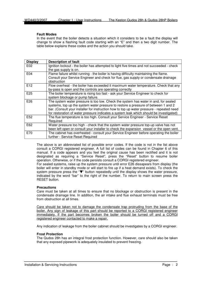
Fault Modes
In the event that the boiler detects a situation which it considers to be a fault the display willchange to show a flashing fault code starting with an “E” and then a two digit number. Thetable below explains these codes and the action you should take.
The cabinet has overheated - consult your Service Engineer before operating the boilerfurther - Service Reset Required
E70
Water pressure too high - check that the system water pressure top-up valve has notbeen left open or consult your installer to check the expansion vessel or the open vent.
E62
The flue temperature is too high. Consult your Service Engineer - Service ResetRequired
E52
The system water pressure is too low. Check the system has water in and, for sealedsystems, top up the system water pressure to restore a pressure of between 1 and 2bar. (Consult your installer for instruction how to top up water pressure - repeated needfor restoration of water pressure indicates a system leak which should be investigated)
E26
The boiler temperature is rising too fast - ask your Service Engineer to check forsystem blockage or pump failure.
E25
Flow overheat - the boiler has exceeded it maximum water temperature. Check that anyby-pass is open and the controls are operating correctly
E12
Flame failure whilst running - the boiler is having difficulty maintaining the flame.Consult your Service Engineer and check for flue, gas supply or condensate drainageobstruction
E04
Ignition lockout - the boiler has attempted to light five times and not succeeded - checkthe gas supply is on.
E02
Description of faultDisplay
The above is an abbreviated list of possible error codes. If the code is not in the list aboveconsult a CORGI registered engineer. A full list of codes can be found in Chapter 6 of thismanual. If a code appears and you feel the original cause has been rectified and it is notdesignated as requiring a “Service Reset”, press the “Reset” button to resume boileroperation. Otherwise, or if the code persists consult a CORGI registered engineer.For sealed systems, raise up the system pressure until error E26 dissapears from display (theboiler will enter in standby mode or will start to fire up if a heat demand exists). To check thesystem pressure press the “” button repeatedly until the display shows the water pressure,indicated by the word “bar” to the right of the number. To return to main screen press theRESET button.
Precautions
Care must be taken at all times to ensure that no blockage or obstruction is present in thecondensate drainage line. In addition, the air intake and flue exhaust terminals must be freefrom obstruction at all times.
Care should be taken not to damage the condensate trap protruding from the base of theboiler. Any sign of leakage of this part should be reported to a CORGI registered engineerimmediately. If the part becomes broken the boiler should be turned off and a CORGIregistered engineer contacted to make a repair.
Any indication of leakage from the boiler cabinet should be investigates by a CORGI engineer.
Frost Protection
The Qudos 28h has an integral frost protection function. However, care should also be takenthat any exposed pipework is adequately insulated to prevent freezing.
WD440/3/2007 Chapter 1 : User Instructions The Keston Qudos 28h & Qudos 28hP Boilers
Installation & Servicing Instructions Page : 2
1.4 SAFETY INFORMATION
IF YOU SUSPECT A GAS LEAK TURN OFF THE APPLIANCE IMMEDIATELY, TURN OFF
THE GAS TAP TO THE APPLIANCE (LOCATED UNDERNEATH) AND CONTACT YOUR
GAS SUPPLIER WITHOUT DELAY.
Benchmark Initiative
As part of the industry wide “Benchmark” initiative Qudos 28 boiler manual includes Gas
Boiler Commissioning Checklist (Chapter 10). This form should be completed by yourinstaller at the end of the installation and commissioning process. The details of the Checklistwill be required in the event of any warranty work being required. There is also Service
Interval Record (Chapter 10) to be completed after each annual service visit.
These forms (Chapter 10) should be kept in a safe place for the life of the boiler.
The boiler should be installed and serviced only by CORGI registered operatives. All CORGIregistered Installers carry a CORGI ID card and have a registration number. Both should be
recorded in your boiler manual (Chapter 10: GAS BOILER COMMISSIONING
CHECKLIST). You can check your installer by calling CORGI direct on 01256 372300.
WD440/3/2007 Chapter 1 : User Instructions The Keston Qudos 28h & Qudos 28hP Boilers
Installation & Servicing Instructions Page : 3

2. GENERAL INSTRUCTION
2.1 DESCRIPTION
The KESTON Qudos 28h and Qudos 28hP boilers utilise the latest in condensingtechnology to produce a high efficiency boilers with SEDBUK A rated efficiency plusadvance controls to maximise operational efficiency.
The Qudos 28h is unique in concept and design. It comprises a high efficiency stainlesssteel heat exchanger coupled with a low emissions burner to deliver ultra high efficiencycondensing mode operation within a compact wall hung cabinet. The unit automaticallyadjusts gas and air rate according to demand to give a heating input in the range of 7.8kWto 29.4kW (GCV).
The Qudos 28h has been developed to embrace the concept of advanced controls toensure the ultra high performance burner and heat exchanger system is run to optimumperformance levels whilst provided or exceeding the comfort levels demanded. As a resultthe boilers feature a host of additional connections for:
- an optional outside sensor to enable the boilers inbuilt weather compensationoption which delivers enhanced user comfort levels with peak operating efficiencydue to the lower flow temperatures involved.
- an optional “Opentherm” connection point for the Keston Room Control modulewhich provides further advanced user control for room temperature compensationand optimum start.
- optional 0-10VDC input where temperature control is provided by external 3rdparty intelligent controls
- optional connection of a DHW thermistor to enable modulated reheat of DHW andoptional legionella prevention function
Further, the Qudos 28h is developed with the concept that the gas boiler in the modernhome is often supplemented by alternative or renewable energy sources. As a result theQudos 28h features:
- optional connection of a solar thermal system, pump, panel and DHW sensor, fordirect control of solar thermal system from the boiler. Other additional energysource systems, such as Ground Source Heat Pump, will be accommodatedsoon.
The boilers have the added advantage of very high efficiency, and small diameter muPVCplastic flue which can be extended up to 20 metres horizontally or vertically.
The Keston Qudos 28h uses a variable speed combustion blower to deliver a premix ofgas and air to a downward firing burner in a high efficiency, single pass heat exchanger.The flue system is room sealed and fan powered. The ignition is direct spark and fullyautomatic. The boiler housing is not waterproof and should be installed in a positionwhere it will always be dry. Combustion air is drawn from the cabinet which is connectedto outside atmosphere via a small diameter plastic intake pipe. The cabinet thereforeremains under negative pressure at all times the boiler is operating.
These boilers are designed for use as part of a sealed or open vented water centralheating system with fully pumped circulation.
The boiler heat exchanger is made from highly corrosion resistant stainless steel incorrugated pipe form which provides massive surface area within a compact dimension.The hot combustion gases from the down firing burner pass around the stainless steelpipes imparting heat into the system water. The Qudos 28h is not a high water contentboiler and does not contain the metal mass, or water volume, of a cast iron or steel boiler.This boiler is of low mass and low water content and therefore responds faster when thereis a call for heat. The Qudos 28h features full user diagnostics, integral frost protection
WD440/3/2007 Chapter 2 : General Instruction The Keston Qudos 28h & Qudos 28hP Boilers
Installation & Servicing Instructions Page : 4

function, automatic pump and fan exercise in periods of inactivity, anti cycle control anddry fire protection.
2.2 BOILER SCHEMATIC
Air is drawn into the boiler through a 50 mm muPVC (BS5255 and/or BSEN1566-1 andBSEN1329) plastic pipe or, alternatively, via a 75mm Keston composite plastic pipe. Gasis mixed with combustion air at the inlet to the fan. The gas flow is automatically regulatedby the gas valve according to the air flow generated by the fan. The gas and air arethoroughly mixed in the blower and fed into the burner located at the top end of the heatexchanger module. The gas and air mixture is ignited by a direct spark ignition controlsystem and burns with a blue flame just off the surface of the burner. As the hot productsof combustion pass downwards, they are cooled by exchanging heat with the circulatingwater which enters the heat exchanger at the bottom of the heat exchanger. The optimumheat input is detected by monitoring flow and return temperatures and is adjusted bycontrolling the speed of the fan.
When the return water temperature is below 55oC, part of the water vapour in thecombustion products will condense inside the heat exchanger, thus increasing the boilerefficiency further by releasing the latent heat of condensation. This condensate falls to thebottom of the heat exchanger where it is separated from the flue gases and exits from theboiler through the condensate drain. Any condensate formed in the flue runs back downthe flueway and is drained at the base of the flue connection to the heat exchanger ordrain points within the flue.
The condensate is very slightly acidic (about the same acidity as vinegar) and should bepiped in a plastic pipe. It is not harmful to the waste disposal system and may be disposedof as normal waste water.
WD440/3/2007 Chapter 2 : General Instruction The Keston Qudos 28h & Qudos 28hP Boilers
Installation & Servicing Instructions Page : 5
ENTER RESET

The flue gases are piped in a 50 mm muPVC (BS5255 and/or and BSEN1329) plastic or,alternatively, 75mm Keston composite plastic pipe to outside. The temperature of the fluegases are usually around 5oC to 10oC above the temperature of the return water. The fluepipe should be terminated outside the building from where they cannot re-enter thebuilding or any other adjacent building.
The heating level may be controlled by room thermostats, programmer time clocks andcompatible energy management systems. An optional Keston room controller can beconnected which will provide enhanced controls such as room compensation to furtherincrease efficiency and comfort levels. However, this is only recommended for heatingonly applications. Once the controls are set the boiler operates automatically. Further, aKeston outside sensor can be connected to the boiler which will automatically invokeweather compensated heating which further boosts user comfort and boiler efficiency.
In the event of the boiler overheating the safety devices will cause a safety shutdown.
The Qudos 28h features an integral frost protection function which will operate the systempump, regardless of the external controls, should the boiler temperature fall below 10oC.
In the event the boiler temperature falls below 5oC the boiler will also fire. This is to avoid
damage to the boiler through freezing of boiler water. The boiler will turn off when the flowtemperature exceeds 15oC.
The Qudos 28h features a system pump exercise function which will run the pump,without firing the boiler, for 10 seconds in the event the boiler is on standby for in excessof 24 hours without firing.This is to help preventseizing of the systempump due to long periodsof inactivity.
2.3 RELATED DOCUMENTS
The Keston Qudos 28hand Qudos 28hPCondensing Boilers mustbe installed in accordancewith the current issue ofthe Gas Safety(Installation and Use)Regulations 1996, currentIEE Wiring Regulations,Building Regulations,Building Standards(Scotland) Consolidation,and the Bye Laws of thelocal Water Undertaking.It is the law that ALL gasappliances are installed bya competent person inaccordance with theabove regulations.
In addition, due accountmust be taken to thefollowing Codes OfPractice:
WD440/3/2007 Chapter 2 : General Instruction The Keston Qudos 28h & Qudos 28hP Boilers
Installation & Servicing Instructions Page : 6
K
O
N
T
S
E

BS 6891 : Gas SuppliesBS 6798 : Installation Central Heating BoilersBS 5449 : Installation Pumped Central HeatingBS 5546 : Installation Domestic Hot WaterBS 5440.1 : FluesBS 5440.2 : Air SupplyBS 5482.1 : Domestic Propane and Butane Burning
InstallationsBS 7074.1 : Expansion VesselsBS 7593 : Treatment of Water in Hot Water Central
Heating SystemsBS 7671 : Requirements for Electrical Installations. IEE
Wiring Regulations 16th Edition.For Timber Framed Buildings, British Gas Publications DM2. Also British GasPublications 'Guidance Notes For The Installation Of Domestic Gas CondensingBoilers' and 'Specification For Domestic Wet Central Heating Systems'.
In IE, the installation must be carried out by a competent person and installed inaccordance with the current edition of IS813 “Domestic Gas Installations”, the currentBuilding Regulation and reference should be made to the current ETC1 rules for electricalinstallations.
No alterations should be made to the boiler without written permission from Keston BoilersLtd. Any unauthorised modification will invalidate the warranty and may affect the safe andefficient operation of the boiler.
WD440/3/2007 Chapter 2 : General Instruction The Keston Qudos 28h & Qudos 28hP Boilers
Installation & Servicing Instructions Page : 7

2.4 PHYSICAL DATA - Qudos 28h & Qudos 28hP
Cabinet Height mm 680Cabinet Width mm 390Cabinet Depth mm 280Top Clearance mm 150Side Clearance mm 5Base Clearance mm 200Front Clearance (for servicing) mm 300Weight - Full kg / (lbs) 39(86)Weight - Empty kg / (lbs) 35(77)Flow and Return Connection G3/4Gas Connection G1/2Condensate Connection overflow 22mm plasticIP Rating IP20 (IPX0)
Flue and Air Intake Material 50mm muPVC (BS5255 and/or BSEN1566-1 and BSEN1329)Flue Pipe Size (nominal bore) mm / (in) 50 / (2)Air Intake Pipe Size (nominal bore) mm / (in) 50 / (2)Max. Air Intake Length m 39Max. Flue Outlet Length m 20Max. Total Flue Outlet and Air Intake Length m 40
Flue and Air Intake Material 75mm Keston CompositeFlue Pipe Size (nominal bore) mm / (in) 75 / (3)Air Intake Pipe Size (nominal bore) mm / (in) 75 / (3)Max. Air Intake Length m 117Max. Flue Outlet Length m 60Max. Total Flue Outlet and Air Intake Length m 120
2.5 OPTIONAL ACCESSORIES
A range of accessories are available from Keston Boilers Ltd to compliment an installation.Terminal wall sealing collars are available to make good the external all face whilst working fromthe inside of the building using 50mm muPVC (BS5255 and/or BSEN1566-1 and BSEN1329)pipe. Stand-off frames are available to leave a 50mm gap behind the boiler to allow routing ofpipes behind the boiler.
Description Part Number
Flue Terminal Wall Sealing Collar (50mm) C.08.0.00.07.0Air Terminal Wall Sealing Collar (50mm) C.08.0.00.07.050/75mm Flue Adapter C.17.2.00.60.0Flue Outlet Terminal (75mm) C.17.2.26.00.0Air Inlet Terminal (75mm) C.17.2.26.00.0Stand Off Back Plate Q.10H.0.01.00.0Outside Temperature Sensor C.10C.0.09.00.0Keston Chronotherm Room Controller C.17.4.21.00.0Remote Fascia Kit Q.10S.0.03.00.0DHW Tank Sensor Q.10S.0.04.00.0Solar Sensors Kit (Panel sensor and 2 x DHW Tank Sensors) Q.10S.0.05.00.0
WD440/3/2007 Chapter 2 : General Instruction The Keston Qudos 28h & Qudos 28hP Boilers
Installation & Servicing Instructions Page : 8

2.6 PERFORMANCE DATA - Qudos 28h & Qudos 28hP
Seasonal Efficiency (SEDBUK) = 91.1 (Qudos 28h) & 93.1 (Qudos 28hP)
This value is used in the UK Government's Standard Assessment Procedure (SAP) for
energy rating of dwellings. The test data from which it has been calculated have been
certified by Advantica Technologies Ltd
Keston Boilers Ltd declare that there are no substances harmful to health within the
appliance or used during the production of the appliance.
The Qudos 28h is intended for domestic and commercial EMC environments and on a
governed G20 meter supply.
The Qudos 28hP is intended for domestic and commercial EMC environments and on a
governed G31 supply.
This boiler meets the requirements of SI 3083 The Boiler (Efficiency) Regulations and is thereforedeemed to meet the requirements of Directive 92/42/EEC. The CE mark on the appliance showscompliance with Directives 90/396/EEC, 73/23/EEC and 89/336/EEC.
IMPORTANT
This product contains ceramic fibre boards, which although not regarded as a risk, contain
ceramic fibre which may cause temporary irritation to eyes, skin and respiratory tract. The
fibres are held in place by inorganic binders. Therefore as long as the boards are not
disturbed they will not be released. Since the boards are non-servicable parts there should
be no risk. Under no circumstances should the user interfere with any sealed parts.
To ensure that the release of fibres from these RCF articles is kept to a minimum, during
installation and servicing we recommend that you use a HEPA filtered vacuum to remove
WD440/3/2007 Chapter 2 : General Instruction The Keston Qudos 28h & Qudos 28hP Boilers
Installation & Servicing Instructions Page : 9
Qudos 28h Qudos 28hP
Nat. Gas (G20) LPG (G31)
Min. Input (Gross CV) kW/(Btu/h) 7.8/(26,600) 7.6/(26,000)Max. CH Input (Gross CV) kW/(Btu/h) 29.4/(100,300) 28.8/(98,300)Max. CH Output To Water
(80/60oC Flow/Return) kW/(Btu/h) 26.4/(90,500) 26.4/(90,500)
(50/30oC Flow/Return) kW/(Btu/h) 28.4/(96,900) 28.4/(96,900)Min. CH Output To Water
(80/60oC Flow/Return) kW/(Btu/h) 7.0/(24,900) 7.0/(24,900)
(50/30oC Flow/Return) kW/(Btu/h) 7.8/(26,600) 7.6/(26,000)Max. Burner Press.-Hot (Factory Preset) mbar/(in w.g) 0/(0) 0/(0)Max. Gas Cons. After 10 mins (DHW) l/s / (Ft3/hr) 0.76/(96.6) 0.35/(45.0)Max. Operating Flow Temp. oC 82 82Max. Press. (Sealed System) bar 2.70 2.50Min. Press/Head (Open System) bar 0.25 (8 feet) 0.25 (8 feet)Inlet Gas Pressure mbar/(in w.g) 20.0 / (8.0) 37.0/(14.8)
Recommended Temp Diff. oC 8 to 20 8 to 20
Electrical Supply 230V 50Hz 230V 50HzPower Consumption (Max) W 80 80Power Consumption (Standby) W 8.5 8.5Type of Gas G20 Natural Gas G31 LPGOptimum Flue Gas CO2 Level (at max CH rate, case on) 9.1 10.5Expected CO/CO2 Ratio (at max CH rate, case on) 0.0007 0.001Destination Countries GB/IE GB/IESEDBUK Efficiency 91.1 93.1NOx Class 5 5

any dust accumulated in and around the appliance before and after working on the appli-
ance. When replacing these articles we recommend that the replaced items are not broken
up, but are sealed within heavy duty polythene bags, and clearly labelled as RCF waste.
RCF waste is classed as a stable, non-reactive hazardous waste and may be disposed at a
landfill licensed to accept such waste. Protective clothing is not required when handling
these articles, but we recommend you follow the normal hygiene rules of not smoking,
eating or drinking in the work area and always wash your hands before eating or drinking.
Benchmark Initiative
As part of the industry wide “Benchmark” initiative Qudos 28h boiler manual includes Gas Boiler
Commissioning Checklist (Chapter 10). This form should be completed by your installer at theend of the installation and commissioning process. The details of the Checklist will be required inthe event of any warranty work being required. There is also Service Interval Record (Chapter
10) to be completed after each annual service visit.
These forms (Chapter 10) should be kept in a safe place for the life of the boiler.
The boiler should be installed and serviced only by CORGI registered operatives. All CORGI regis-tered Installers carry a CORGI ID card and have a registration number. Both should be recorded
in your boiler manual (Chapter 10: GAS BOILER COMMISSIONING CHECKLIST). You cancheck your installer by calling CORGI direct on 01256 372300.
WD440/3/2007 Chapter 2 : General Instruction The Keston Qudos 28h & Qudos 28hP Boilers
Installation & Servicing Instructions Page : 10
IN THE EVENT OF A GAS LEAK
Turn off the gas isolation valve to the property immediately. Extinguishall naked flames or other sources of ignition. Do not operate electricalswitches on or off. Open all doors and windows to ventilate the area.
3. BOILER LOCATION
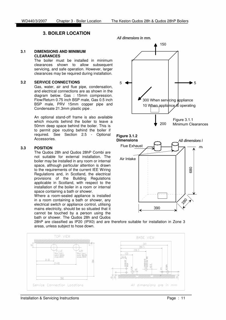
3.1 DIMENSIONS AND MINIMUM
CLEARANCES
The boiler must be installed in minimumclearances shown to allow subsequentservicing, and safe operation. However, largerclearances may be required during installation.
3.2 SERVICE CONNECTIONS
Gas, water, air and flue pipe, condensation,and electrical connections are as shown in thediagram below. Gas : 15mm compression.Flow/Return 0.75 inch BSP male, Gas 0.5 inchBSP male, PRV 15mm copper pipe andCondensate 21.3mm plastic pipe .
An optional stand-off frame is also availablewhich mounts behind the boiler to leave a50mm deep space behind the boiler. This isto permit pipe routing behind the boiler ifrequired. See Section 2.5 - OptionalAccessories.
3.3 POSITION
The Qudos 28h and Qudos 28hP Combi arenot suitable for external installation. Theboiler may be installed in any room or internalspace, although particular attention is drawnto the requirements of the current IEE WiringRegulations and, in Scotland, the electricalprovisions of the Building Regulationsapplicable in Scotland, with respect to theinstallation of the boiler in a room or internalspace containing a bath or shower.Where a room-sealed appliance is installedin a room containing a bath or shower, anyelectrical switch or appliance control, utilisingmains electricity, should be so situated that itcannot be touched by a person using thebath or shower. The Qudos 28h and Qudos28hP are classified as IP20 (IPX0) and are therefore suitable for installation in Zone 3areas, unless subject to hose down.
WD440/3/2007 Chapter 3 - Boiler Location The Keston Qudos 28h & Qudos 28hP Boilers
Installation & Servicing Instructions Page : 11
All dimensions in mm.
150
300 When servicing appliance
200Figure 3.1.1Minimum Clearances
55
10 When appliance is operating
All dimensions in mm.
390
280
Figure 3.1.2
Dimensions
Flue Exhaust
Air Intake
680
mm
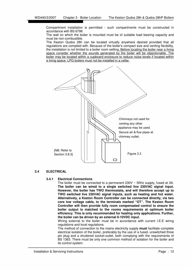
Compartment installation is permitted - such compartments must be constructed inaccordance with BS 6798.The wall on which the boiler is mounted must be of suitable load bearing capacity andmust be non-combustible.The Keston Qudos 28h can be located virtually anywhere desired provided that allregulations are complied with. Because of the boiler's compact size and venting flexibility,the installation is not limited to a boiler room setting. Before locating the boiler near a livingspace consider whether the sounds generated by the boiler will be objectionable. Theboiler may be located within a cupboard enclosure to reduce noise levels if located withina living space. LPG boilers must not be installed in a cellar.
3.4 ELECTRICAL
3.4.1 Electrical Connections
The boiler must be connected to a permanent 230V ~ 50Hz supply, fused at 3A.The boiler can be wired to a single switched live 230VAC signal input.
However, the boiler has TWO thermostats, and will therefore accept up to
TWO switched live 230VAC signal inputs, such as heating and hot water.
Alternatively, a Keston Room Controller can be connected directly, via two
core low voltage cable, to the terminals marked “OT”. The Keston Room
Controller will then provide fully room compensated control to ensure the
boiler output is matched to the rooms requirements at optimum boiler
efficiency. This is only recommended for heating only applications. Further,
the boiler can be driven by an external 0-10VDC input.
Wiring external to the boiler must be in accordance with current I.E.E wiringregulations and local regulations.The method of connection to the mains electricity supply must facilitate completeelectrical isolation of the boiler, preferably by the use of a fused, unswitched threepin plug and a shuttered socket-outlet, both complying with the requirements ofBS 1363. There must be only one common method of isolation for the boiler andits control system.
WD440/3/2007 Chapter 3 - Boiler Location The Keston Qudos 28h & Qudos 28hP Boilers
Installation & Servicing Instructions Page : 12
Chimneys not used forventing any otherappliance may be used.
Figure 3.3
Secure air & flue pipes atchimney outlet.
[NB: Refer to
Section 3.8.3]

The appliance must be connected to the 3A supply via a fused double-pole switchhaving at least 3 mm (1/8 inch) contact separation in both poles, serving only theboiler and the system controls.The connection point to the mains supply should be readily accessible andadjacent to the boiler, except for rooms containing a bath or a shower. Refer tosection 3.3 Position.
3.4.2 External Wiring & Controls
1. The boiler is designed so that all control wiring is external to the boiler. 2. Heating control signal inputs must the 230VAC "switched live" type unless
using a Keston Room Controller (see below) or 0-10VDC input.3. The system pump must also be wired back to the boiler to enable the
boiler to provide pump overrun and pump exercise function.
3.4.2.1 Enhanced Control Options
The Qudos 28h can be wired into a conventional heating installation using onlypermanent and switched live connections and pump connection.
However, the Qudos 28h features a wide range of OPTIONAL control featuresnormally associated with commercial boilers installations at additional cost. Theseare provided as standard in the Qudos 28h and require low costs sensors to beadded to activate them. The features provided are detailed below. Refer toChapter 4.8 for further wiring detail.
Room Compensation (Opentherm)A Keston Room Controller may be used to provide room compensatedcontrol to ensure the boiler output is matched to the rooms requirementsat optimum boiler efficiency. This is only recommended for heating onlyapplications
Weather Compensation (Ext Sensor)A Keston outside temperature sensor may be connected as an option.The boiler will automatically detect this connection and will operate on a"weather compensation" basis when receiving a heating demand signalfrom the SL terminal or from a Keston Room Controller. Screened cable(80% density) must be used to connect the outside temperature sensor.
Solar Control Where a solar thermal system is in use, with a twin coil cylinder such asthe Kesotn SpaTwin, the Qudos 28h will control operation of the solarpump in conjunction with the boiler. The boiler requires connection to thesolar tank sensor, solar panel sensor and solar pump
Modulating DHW ReheatThe Qudos 28h can provide direct modulation to maximise the re-heatperformance of the DHW cylinder. A DHW cylinder sensor can beconnected directly to the Qudos 28. A DHW demand input can also beprovided to control DHW reheat activity, perhaps in conjunction with SolarThermal. With this facility connected an automatic anti-legionnella facilitycan also be provided.
Analog Demand (0-10VDC)Where external control panels are used, in boiler room applications, a0-10VDC input can be connected to the boiler, in place of the SL1switched live demand. The 0-10VDC signal will drive the first setpoint at1VDC = 10C setpoint (NB: <0.5VDC is off, >8.0 VDC is 80C)
External Lockout SignalWhere remote monitoring and/or alarms are installed the boiler offers a
volt-free lockout signal output. The boiler will provide a closed circuit across the two output points when the boiler is in lockout.
WD440/3/2007 Chapter 3 - Boiler Location The Keston Qudos 28h & Qudos 28hP Boilers
Installation & Servicing Instructions Page : 13

Remote Fascia PanelFor installations where the boiler is located outside of the living area, such as theloft or an out-house, a remote fascia control can be fitted within the living area.This will provide full functionality normally accessed via the boiler fascia panel.
3.5 BOILER SIZE SELECTION
The Qudos 28h will automatically adjust heat output to match the system requirements atany given time. Efficiency and combustion levels are maintained at optimum levelsthroughout the possible output range. The Qudos 28h is therefore suitable for all systemswith a total heat load within the maximum range of the boiler.
3.6 GAS SUPPLY
A gas meter should be connected to the service pipe by the local gas region or theircontractor. An existing meter should be checked preferably by the gas region to ensurethat the meter is adequate to deal with the rate of gas supply required. Installation pipesshould be fitted in accordance with BS 6891.Minimum/Maximum Gas Pressure:
Natural gas pressure before the gas valve must be maintained at between 18 mbar (7.2 inWG) and 22 mbar (8.8 in) while the boiler is running.LPG pressure must be maintained between 31.5 mbar (12.4 in w.g) and 37.6 mbar (14.8in w.g) while the boiler is running.Gas pressures above or below these levels will lead to problems associated with the gasvalve's internal pressure regulator.Supply pipes to the boiler must not be sized less than the boiler inlet connection
(15 mm). Due consideration must be given to the supply pressure to other gas
appliances in the premises. Reduction in dynamic gas supply pressure will result in
intermittent ignition failures. Ensure gas supply pipe work is adequately sized for
the length of run from the meter to the boiler at a supply rate of 28.4kW (i.e. a naturalgas supply should be considered to be a minimum of 22mm diameter, reducing to 15mmat the boiler. If gas runs greater than 12m, including the allowance for bends, are involvedthe pipe size should be increased further).
3.7 WATER SYSTEMS
All piping must be installed in accordance with all applicable local and Water SupplyBylaws for forced hot water heating systems.Consideration must be given to pipe capabilities and pressure drop through the pipingwhen selecting pipe sizes. The primary pipe connections to the boiler must be sizedaccording to the system load, not dictated by the boiler connection sizes.Water treatment must be carried out to BS 7593 : Treatment of Water in Hot WaterCentral Heating Systems.In IE the requirements given in the current edition of IS813 and the current BuildingRegulations must be followed.
a The Keston Qudos 28h is designed for installation on sealed or open-ventedwater systems. With fully pumped water circulation.
b Any system must be thoroughly flushed clean of grease, dirt and debris, prior toconnection with the boiler. A trap may be installed in the flow line to collect anysolder, or other debris, from the installation.
c All water systems must be constructed to comply with requirements of the LocalWater Authority.
d Always use a system complying with the requirements of BS 5449 and BS 6798.e System design must ensure an open circuit is always available to ensure
circulation when the pump overrun function is operating after boiler shutdown.f Isolation valves must be fitted on the flow and the return to enable isolation when
maintaining the boilerg Copper tubing to BS 2871 Part 1 or barrier plastic pipe suitable to 110 oC, such as
Unipipe, is recommended.
WD440/3/2007 Chapter 3 - Boiler Location The Keston Qudos 28h & Qudos 28hP Boilers
Installation & Servicing Instructions Page : 14

.
WD440/3/2007 Chapter 3 - Boiler Location The Keston Qudos 28h & Qudos 28hP Boilers
Installation & Servicing Instructions Page : 15
Pump
Valve
Safety
Relief
Valve
bib tapHose Union
HoseStop TapBS 1010:2
RETURN
HEATING CIRCUIT
FLOW
CockTest Connector
after filling)(disconnectedHosepipe
VesselExpansion
KESTON
Qudos 28h
Dbl Check
By-pass
CockDrain
Figure 3.7.1: Sealed Systems Diagram
L/S
Air Vent
RETURN
Rad. 2 Rad. 1
FLOW
Expansion
Pipe
ValveL/S
Minimum
8ft Height
Minimum
22mm
Tank
Expansion
Cylinder
KESTON
Qudos 28h
Pump
Figure 3.7.2 : Open Vented Systems Diagram
ValveBy-pass 3-Way
Valve
h Jointing should be either with capillary, threaded or compression fittings. Pipesshould have a gradient to ensure air is passed easily to vent points and waterflows readily to drain points.
i Draining taps must be located in accessible positions which permit the draining ofthe boiler. Draining taps should be at least 22 mm in nominal size and be inaccordance with BS 2879.AIR VENT POINTS
j These must be fitted at all high points where air will naturally collect and must besited to allow complete draining of the system.
k A filling point must be fitted, in accordance with local water authorityrequirements.
m The installation must be designed to work with flow temperatures of up to 110 oC.lll components of the system must be suitable for a working pressure of 3 bar anda temperature of 110 oC. Care should be taken in making all connections that therisk of leakage is minimised.
3.7.1 Boiler By-pass Piping
Boiler water flows are critical to the operation of the boiler. If flow cannot be maintainedthrough the system piping to meet the minimums required by the boiler, insufficient waterflows through the boiler will cause the boiler to "kettle" or even produce steam which candamage the heat exchanger and will invalidate the heat exchanger warranty. In addition,an open circuit is required after boiler shutdown to permit circulation during the boilers 2minute pump overrun sequence.It is advisable to incorporate a boiler by-pass in the system, especially if thermostaticradiator valves are used. The flow/return differential should be 10oC to 20oC. To comply
with the Building Regulations Part L1 the bypass must of the automatic type.
3.7.2 Air Elimination
In the initial charge of water to the boiler system and in all subsequent additions of waterto the system some air will be dissolved in the water. As the water is heated the air isdriven out of the solution and will collect in high spots in the system. These air bubbles
can interfere with pumping and heat transfer and must be eliminated.
Installation of air bleed valves at the highspot(s) in the system will allow for airelimination when filling the system andwill allow re-venting in a day or so afterall air has been driven out of solution.
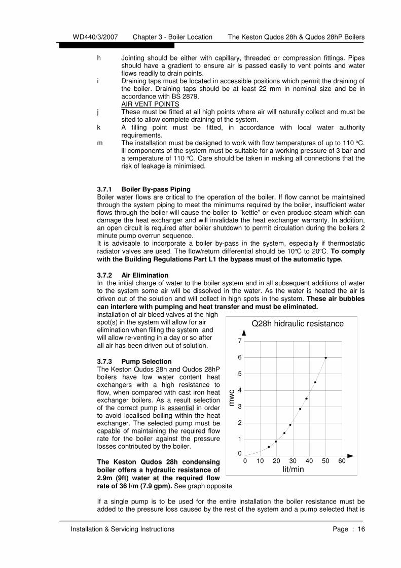
3.7.3 Pump Selection
The Keston Qudos 28h and Qudos 28hPboilers have low water content heatexchangers with a high resistance toflow, when compared with cast iron heatexchanger boilers. As a result selectionof the correct pump is essential in orderto avoid localised boiling within the heatexchanger. The selected pump must becapable of maintaining the required flowrate for the boiler against the pressurelosses contributed by the boiler.
The Keston Qudos 28h condensing
boiler offers a hydraulic resistance of
2.9m (9ft) water at the required flow
rate of 36 l/m (7.9 gpm). See graph opposite
If a single pump is to be used for the entire installation the boiler resistance must beadded to the pressure loss caused by the rest of the system and a pump selected that is
WD440/3/2007 Chapter 3 - Boiler Location The Keston Qudos 28h & Qudos 28hP Boilers
Installation & Servicing Instructions Page : 16
1
2
3
4
5
6
7
20 30 40 50 60
lit/min
mw
c
1000
Q28h hidraulic resistance

capable of meeting the flow rate required at the total pressure loss generated by the boilerand the rest of the system. The selected pump must comply with BS 1394. It is importantto note that the minimum flow rate must be maintained whenever the boiler is firing.Systems using zone valves must be specifically designed to only fire the boiler when the
pump is running and the minimum flow rate can be achieved.
3.7.4 Hot Water System (if applicable)
The hot water storage vessel must be of the indirect type (certain direct cylinders can beused provided they are suitably adapted by fitting an immersion calorifier). DIRECTCYLINDERS MUST NOT BE USED. Further guidance is provided in BS 1394. It isadvisable to fit a locksheild valve on the cylinder return to enable balancing of the flow ratethrough the cylinder.The Keston qSpa range of stainless steel unvented cylinders are an ideal option for
use with the Keston range. The Keston qSpa range combine exceptional recovery
times with durable, long life stainless steel construction and all associated
controls. Contact Keston Boilers Ltd for information
The Qudos 28h also has advance control options built in which enable modulated reheatof DHW and anti-legionella function. Refer to Chapter 4 for more detail.
3.7.5 Filling The System (sealed systems only)The system should be filled using a G24 approved filling loop. The system pressureshould be set to between 1.0 and 2.0 bar.
3.8 FLUE SYSTEM
NB: When installing a replacement
boiler a new flue system must be
used. Do not re-use the existing
boiler flue installation.
3.8.1 Design
Individual air supply and flue outlet pipes areused. The material used for flue outlet &/or airinlet must be muPVC to BS 5255 and/orBSEN1566-1 and BSEN1329 of an internaldiameter of 51 mm. (i.e. nominal 50 mmdiameter muPVC solvent weld waste pipe)
Alternatively, where flue or air intake lengths of up to 60m are require, Keston Composite75mm flue and air pipe can be used (contact your Keston stockist for details). KestonComposite 75mm pipe MUST be painted where exposed to UV light.
Both 50mm flue outlet terminal and 50mm air inlet terminal are supplied and are illustratedin Figure 3.8.1. Both terminals are identical. If 75mm terminals are required these can beobtained from your Keston Boilers stockist. Request part numbers C.17.2.26.00.0(terminals) and C.17.2.00.60.0 (50 to 75 adapters).
3.8.2 Maximum Lengths
The maximum lengths of both air inlet pipe and flue outlet pipe, when no bends are used, are as detailed below.
However, each bend used has an equivalent length that must be deducted from themaximum straight length stated above. Knuckle bends must not be used.
A 92.5o sweep elbow is equivalent to 1.0m straight length. A 45o bend is equivalent to0.5m straight length.
WD440/3/2007 Chapter 3 - Boiler Location The Keston Qudos 28h & Qudos 28hP Boilers
Installation & Servicing Instructions Page : 17
Flue Outlet/Air Inlet Terminals
Figure 3.8.1 : Terminals

50mm 75mm
Maximum Air Inlet Length : 39.0m 117.0mMaximum Flue Outlet Length: 20.0m 60mMaximum Total Flue and Air Intake Length : 40.0m 120.0m
Example (assuming 50mm muPVC flue andair pipework)
Air inlet uses two one 92.5o sweep elbows.Hence, maximum length permissible (i.e. a+b in figure 3.8.2) = 39.0m - 1.0m - 1.0m= 37.0m
Flue outlet uses one 92.5o sweep elbow.Hence, maximum length permissible (i.e. c+din figure 3.8.2 = 20.0m - 1.0 m = 19.0m
3.8.3 Slope
‘Horizontal' flue outlet pipework MUST slope atleast 2 degrees (32 mm per metre run)downwards towards the boiler. Pipework can be vertical. Only swept elbows can be used.
Air inlet pipework can be truly horizontal orvertical, or sloping in a downward directiontowards the boiler but in this case rain, etc.,must be prevented from entering the pipe.There must be no troughs in any of the
pipework, whether it be air inlet or flue
outlet.
Due the low temperature of the flue gasesfurther condensate will form within the fluesystem. Drain points, with suitable traps, musttherefore be incorporated within the flue systemat the base of vertical flue sections in excess of6m, for 50mm muPVC pipe flue systems. Theseadditional condensate drains must be run todischarge as detailed in section 3.11. Such drainpoints can be formed using standard muPVC
fittings. Refer to the example in Figure 3.8.3.
3.8.4 Terminations Air inlet terminals must be facing horizontally or downwards to prevent entry of rain intothe terminal and positioned to ensure only fresh air is drawn into the boiler. The airterminal must be located outside of the building.Flue and air terminals must be positioned so that flue products are not drawn into the airinlet. Site specific wind conditions should be considered to achieve this.Drawing of combustion air directly from a ventilated boiler room invalidates the heatexchanger warranty.The flue outlet terminal is designed to face outwards but can, if desired, be adapted toface in any direction BUT must not be directed in the region of the air inlet. The flueterminal and air inlet terminal can be located on different, but not opposing wall faces.The two terminals are subject to the requirements of BS 5440 Pt 1 for clearances fromfeatures of the building although some can be decreased to the values indicated.
WD440/3/2007 Chapter 3 - Boiler Location The Keston Qudos 28h & Qudos 28hP Boilers
Installation & Servicing Instructions Page : 18
Figure 3.8.2 : Flue & Air Maximum Length Example
FLUE
cd
AIR
ab
KESTON Qudos 28h
6 in min.
Figure 2.8.3 :Flue Condensate DrainPoint Example
Tee FittingTo Boiler
To T
erm
inal

The Keston Qudos 28h and Qudos 28hP, as with any condensing boiler, will
generate a condensate “plume” from the flue terminal in all weather conditions.
Consideration must therefore be given to the effect of this “plume” when selecting
a location for the flue terminal. It is the responsibility of the installer to ensure the
selected terminal location does not cause nuisance.
300300L Horizontally from terminal on same wall.
1,5001,500K Vertically from terminal on same wall.
1001,200J From opening in a car port.(not recommended)
1,2001,200I From terminal facing a terminal.
100600H From surface or boundary facing a terminal *
100200G Above ground or balcony or roof.
50200F From internal or external corner or to aboundary alongside the terminal. *.
5075E From vertical drain or soil pipes.
50200D Below balconies or car port roof (lowest point).
50200C Below eaves.
7575B Below gutters, soil pipes, drain pipes.
50300A Below, above or beside openable window, airbrick, etc.
Air
Inlet
Flue
Terminal
Dimensions (mm)
*The dimensions given in the table above may need to be increased to avoid wallstaining and nuisance depending on site conditions.It is advisable for horizontal flue terminals to place a 45o elbow at the end of theflue to direct the condensate plume up and away from the property. If the airintake is within 500mm of the flue outlet the air must not terminate at a levelabove that of the flueIf either the air inlet or flue outlet terminate at a height of less than 2.1m aboveground level, the terminal must be protected by a suitable guard. The K4 terminalguard (with plastic coating), manufactured by Tower Flue Components Ltd issuitable for this purpose
3.8.5 Clearances From Wall
Flue outlet and air inlet terminations must be at least 40 mm from the wall face.
3.8.6 Distance Between Flue Outlet & Air Inlet
There is no maximum - the terminations must not be on opposite sides of thedwelling but can be in areas of unequal pressure.A minimum clearance of at least 200 mm must be left between the terminations.
3.8.7 General Installations
All parts of the system must be constructed in accordance with BS 5440 Part 1,except where specifically mentioned in these instructions.All pipe work must be adequately supported.All joints other than approved push-on or plastic compression connectors must bemade and sealed with solvent cement suitable for muPVC pipes and conformingto BS 6209: 1982.External wall faces and any internal faces of cavity walls must be made good.Rubber collars are available for flue and air terminals to finish the external wallface around the terminals (Part No C.08.0.00.07.0)
3.9 AIR SUPPLY
The KESTON Qudos 28h and Qudos 28hP are room sealed appliances and therefore donot require purpose provided ventilation to the boiler room for combustion air.
WD440/3/2007 Chapter 3 - Boiler Location The Keston Qudos 28h & Qudos 28hP Boilers
Installation & Servicing Instructions Page : 19

3.10 COMPARTMENT INSTALLATION
Due to the low casing temperatures generated by the boiler, no compartment ventilation isrequired. However, the cupboard or compartment must not be used for storage.
3.11 CONDENSATE DRAINAGE
Being a condensing boiler, the Qudos 28h and Qudos 28hP are fitted with a condensatetrap at the base of the heat exchanger and flue assembly, with facility to connect to adrain point underneath the appliance.
The condensate trap is packed loose with the appliance and MUST be fitted
and secured BEFORE firing the appliance.
Use only plastic piping and do not reduce below 15 mm internal diameter within thedwelling. Condensate should preferably be drained into the sanitary waste system or,alternatively, the rainwater system of the property in most cases. Ensure in all cases thatthe disposal of the condensate is in accordance with any local regulations in force.
Termination of the pipe must be either at a branch or stack internal to the house, orexternally at an open gully. Alternatively, discharge into a purpose made condensatesoakaway can be considered. Existing or purpose built drains must use suitable corrosionresistant material as condensate is mildly acidic.
The connection to the condensate drain of the boiler, and the condensate drain pipeworkitself, should be properly sealed to ensure there is no possibility of leakage into thedwelling.
A minimum slope downwards towards the drain of 1 in 20 is essential. Freezing of thetermination and pipework must be prevented. Any drainage pipes outside the propertymust be at least 32 mm inside diameter.
WD440/3/2007 Chapter 3 - Boiler Location The Keston Qudos 28h & Qudos 28hP Boilers
Installation & Servicing Instructions Page : 20

4. INSTALLATION OF THE BOILER
Read Chapter 3 - Boiler Location and decide upon the position of the boiler.
Installation of the boiler is straightforward but consideration must be given to access to allow flueand air pipes to be pushed through walls and ceilings. The order in which the components areinstalled will depend upon particular site conditions, but in general it will be easiest and mostaccurate to install the boiler and then build up the flue outlet and air inlet pipes to the terminal - thisis the sequence described.
4.1 WALL MOUNTING BRACKET
a Place the bracket on thewall horizontally with thepre-drilled holes at thebottom and position asdictated by the templatesupplied within the boilerpackaging.
b Drill through the centrehole of the bracket, plugthe hole and fix in position.
c Using a spirit level makesure the bracket iscompletely level and markthe position of the otherscrew holes.
d Remove the bracket anddrill the holes in thepositions marked. Plug
these holes.
e Screw the bracket to thewall using screws of anappropriate size for the walltype (No. 12 x 2 inch woodscrews normally suffice).
4.2 MOUNTING THE BOILER (after system cleaning and testing)a Lift and locate the boiler onto the stud and the two locating pegs protruding from
the wall bracket. (lift the boiler via the back frame only)b Lower the boiler for hanging on the two pegs.c Fix the boiler on the bracket stud using the nut and the washers supplied.d Fit the condensate trap and secure in positione Make the gas, flow, return, condensate and PRV connections to the system.
Check all joints for tightness.DO NOT FIRE THE BOILER UNTIL THE CONDENSATE TRAP IS SECURED INPOSITION
4.3 ASSEMBLY PRACTICE
Remove all plastic debris and burrs when installing air intake piping. Plastic filings causedby cutting muPVC pipe must not be allowed to be drawn into the combustion air blower.Prevent dust entering the air intake when cutting on building sites. Blower failure which isdetermined to be caused by plastic filings or other debris will not be covered by guarantee.
4.4 INSTALLING FLUE AND AIR PIPES
IMPORTANT - When installing the boiler on an existing system a new flue and air
intake system MUST also be installed. You must NOT re-use existing flue or air
pipework components.
WD440/3/2007 Chapter 4 : Installation The Keston Qudos 28h & Qudos 28hP Boilers
Installation & Servicing Instructions Page : 21
All dimensions in mm.
Figure 4.1 Wall Mounting Fixing Locations
158.3

NB: When installing the boiler, consider:
Flue Spigot Assembly
The flue spigot (50mm muPVC) is inside the accessory bag.Put the flue spigot assembled with the test plug on the cabinet frame and secureit by fastening the two M6 screws. Couple the spigot to the internal flue pipe usingthe flexible couple and fastening clips. Ensure the clips are properly secured andno leakage can occur.Remember the flue pipe must slope downwards back towards the boiler and thisis best achieved using 92.5o bends.
a Using the template supplied within the boiler packaging mark the positions of the two holes for the flue and air pipes on the wall(s) or ceiling.
b Drill the two holes in the wall/ceiling, preferably using a core drill.c Measure, cut and check the air and flue pipes to pass to the exit from the
wall(s) or ceiling.Always thoroughly deburr all pipes and, most important, remove shavings fromwithin the pipe.
d Mount the boiler on the wall bracket and fix the air spigot (packed loosewith the boiler and with appropriate gasket) to the boiler air inletconnection tightly to ensure there is no leakage. Assemble, usingadhesive, the pipework from the boiler connections to the exit from thefirst wall/ceiling (remount the boiler if removed). When pushing pipethrough walls, ensure grit and dust is not allowed to enter the pipe.Ensure pipes are fully engaged into sockets and solvent welded with noleaks.
e Using the same methods drill any further holes (always covering existingpipework), cut and assemble the pipework.
f From outside, complete the two terminations - See Section 3.8 FlueSystem and make good all holes. (wall sealing collars are available tomake good hole areas on the wall face (part number C.08.0.00.07.0)
g Support any pipes whose route could be displaced either of its ownaccord or by accident. Any horizontal run over 1m or vertical runs of anylength must always be supported. Brackets should be placed at intervalsof approximately 1m.
h Check all connections for security and re-seal any joints using solventcement where soundness may be in doubt.
Note: It is equally important to seal the air inlet with solvent cement as the flue outletpipe joints.
4.5 CONDENSATE DRAINAGE
NB: When installing the boiler, consider:
Condensate Trap Assembly
The condensate trap is fitted loose inside the cabinet.i) Fit the condensate trap through the hole in the base of the boiler frame.ii) Remove the cap fitted to the condensate drain spigot at the base of the
heat exchanger.iii) Securely connect the condensate trap inlet to the heat exchanger drain
spigot. Be carefully to the correct position of sealing O-ring.Iv) Secure the trap to the boiler frame using the fixing bolts supplied.
Connect the condensate drainage system to the boiler. It is advisable to use a detachablefitting at connection to the boiler to enable easy removal for servicing.Fill the condensate trap by pouring water into the boiler flue until water is seen to flowfreely from the condensate drainage system. Make the final connection of flue pipe to theboiler.
Details are provided in Chapter 3 - Section 3.11 Condensate DrainageConnection : 22 mm plastic pipe.
WD440/3/2007 Chapter 4 : Installation The Keston Qudos 28h & Qudos 28hP Boilers
Installation & Servicing Instructions Page : 22
4.6 WATER SYSTEM
Connect the flow and return HEATING CIRCUIT system pipework to the boiler. Details ofsystem requirements are given in Chapter 3 - Section 3.7 Water Systems.
Connections : 0.75 inch BSPM
For optimum performance after installation, this boiler and its associated central heatingsystem must be flushed in accordance with the guidelines given in BS7592:1992,"Treatment of water in domestic hot water central heating systems".This must involve the use of a proprietary cleaner, such as Fernox Superfloc, orBetzDearborn's Sentinel X300 or X400. Full instructions are supplied with the products,but for immediate information, please contact Fernox on 01799 550811 or BetzDearbornon 0151 420 9563.For long term protection against corrosion and scale, after flushing, it is recommendedthat an inhibitor such a Fernox MB1 or BetzDearborn's Sentinel X100 is dosed inaccordance with the guidelines given in BS7593:1992.
4.7 GAS SUPPLY
Connect the gas supply to the appliance. Details of gas supply requirements are given inChapter 3 - Section 3.6 Gas Supply. Supply of adequate gas pressure (with the boiler
running) is critical to ensure reliable operation of the boiler.Connections : 0.5 inch BSPM
4.8 ELECTRICAL SUPPLY
The entry point(s) for the electrical supply cable(s) is in the base of the appliance (seeSection 3.2 Service Connections fig. 3.1.2) via a cordgrip bush. Feed the cable throughthe bush and route inside the cabinet to the connection strip located to the front bottomright area of the cabinet.
1. The electrical supply must be as specified in Chapter 3 - Section 3.4 ElectricalSupply.WARNING : THIS APPLIANCE MUST BE EARTHED.
2. All external controls and wiring must be suitable for mains voltage. Supply wiringshould be in PVC insulated cable not less than 0.75mm2 (8.0mm dia) to BS 6500Table 16 (material code H05VV-F).
3. The permanent live supply connection may be via a 3 amp fused double poleswitch, serving only the boiler. (Refer to Chapter 3 - Section 3.4 Electrical Supply).Any 230VAC system controls for the boiler must also be supplied via this isolator.
4. Basic Wiring InstallationSecurely tighten the terminal screws and route the cable(s) through there-openable cable clips. Ensure all cables are secured and that the cord grip bushis tightened to securely grip the main cable at entry to the cabinet. Remove thefactory fitted link wire between the room thermostat terminals on the boiler.The supply cable(s) must be connected to the main terminals as follows:-
Main Supply L - Brown wire (Live) 3A permanent supplyMain Supply N - Blue wire (Neutral) for 3A permanent
Main Supply E - Yellow/Green Wire (Earth)CH Demand SL1 - 230V Switched Live - i.e. Room Thermostat
System Pump L - Brown wire (Live) to system pumpSystem Pump N - Blue wire (Neutral) to system pumpSystem Pump E - Yellow/Green wire (Earth) to system pump
Ensure connection is made such that if the cable slips in its anchorage the currentcarrying conductors become taut before the earthing conductor.
WD440/3/2007 Chapter 4 : Installation The Keston Qudos 28h & Qudos 28hP Boilers
Installation & Servicing Instructions Page : 23

4.9 Advanced Features Wiring
The Qudos 28h features comprehensive and advance functionality as standard.Whilst these advances funtions are not mandatory, they will provide enhancedboiler operation performance and efficiency. Detailed below are suggested wiringmethods to activate various functions.
4.9.1 Twin Thermostat Operation with Weather Compensation
4.9.2 Modulation of DHW generation
WD440/3/2007 Chapter 4 : Installation The Keston Qudos 28h & Qudos 28hP Boilers
Installation & Servicing Instructions Page : 24
SYSTEM PUMPEN
SY
ST
EM
PU
MP L
SEPARATE CH & DHW DEMAND WITH ( OPTIONAL ) WEATHER COMPENSATION
CONTROLS
FROM DHW
CONTROLS
FROM CH
( OPTIONAL )
EXTERNAL SENSOR
GREYORANGE
BROWNBLUE
M
VALVEDHW ZONE
VALVE
CH ZONE
BROWN
GREY
BLUE
ORANGE
M
( 3
A F
US
E )
230V
MA
IN S
UP
PL
Y
E
N
L
BOILER
MA
IN C
ON
NE
CT
OR
LOW VOLTAGE CONNECTOR
Q28H
E
THERMSWITCH
C 2 1
CH1
10-10V 0v 2
SENSOR
1 2
SENSOR
2
SENSOR
1 12 NO
OPENSOL. DHWTS FLOW ANALOGDEMAND
EXTERNALSENSOR
MA
IN S
UP
PL
YS
OL
AR
PU
MP
CH
DE
MA
ND
1N
NS
L1
SL
2E
L
LO
CK
OU
T
CO
MN
O2
C.10C.0.09.00.0
EXTERNAL SENSOR
C.10C.0.09.00.0SY
ST
EM
PU
MP L
NE SYSTEM PUMP
2N
OC
OM
LO
CK
OU
T
LE
SL
2S
L1
NN
1
CH
DE
MA
ND
SO
LA
R P
UM
PM
AIN
SU
PP
LY
SENSOREXTERNAL
DEMANDANALOGFLOWTS DHWSOL. OPEN
NO2 11
SENSOR
2
SENSOR
21
SENSOR
20v0-10V1
CH1
12C
SWITCH THERM
E
Q28H
LOW VOLTAGE CONNECTOR
MA
IN C
ON
NE
CT
OR
BOILER
L
N
E
230V
MA
IN S
UP
PL
Y
( 3A
FU
SE
)
M
ORANGE
BLUE
GREY
BROWN
CH ZONE
VALVE
DHW ZONE
VALVE
MBLUE BROWN
ORANGE GREY
FROM CH
CONTROLS
FROM DHW
CONTROLS
SEPARATE CH & DHW DEMAND WITH ( OPTIONAL ) DHW SENSOR CONTROL
DHW SENSOR
( OPTIONAL )
TANK
( OPTIONAL )

4.9.3 Solar Control
4.10 EXCHANGING A BOILER
Before removing an existing boiler add Fernox Supafloc, or equivalent cleaning agent, inaccordance with the manufacturers instructions. Open all radiator valves and fire theboiler. When the system is fully heated, shut off the gas supply and drain down the centralheating system.ImportantThe Qudos 28h and Qudos 28hP condensing boilers contain components which could bedamaged or blocked by grease, dirt or solder etc. It is essential that sludge or scale isremoved from an existing system before fitting the boiler.The guarantee provided with the Keston Qudos 28h and Qudos 28hP does not coverdamage caused by system debris or sludge.Connect the new boiler as instructed in this manual and fit in accordance with Sections4.1 to 4.8Fill to a pressure of about 2.5 bar, if on a sealed system. Check the complete system forwater soundness. If leaks need to be rectified using flux or solder the system must beflushed cold again before proceeding.Reduce the pressure to the Initial System Design Pressure, if on a sealed system. Ventthe system.
Gas Supply
The complete gas installation up to the boiler gas control valve must be checked forsoundness. BS 6891.
Electrical Installation
Carry out preliminary electrical safety checks, i.e. Earth continuity, Polarity, Resistance toEarth, Short Circuit and earth loop impedance using a suitable test meter.
Initial Firing
The gas pressure setting is factory adjusted to within the required range and does
not need readjustment. If the reading is incorrect then check such factors as tightnessof the air and flue pipe joints, pressure sensible joints and the gas inlet pressure
WD440/3/2007 Chapter 4 : Installation The Keston Qudos 28h & Qudos 28hP Boilers
Installation & Servicing Instructions Page : 25
SY
ST
EM
PU
MP
SYSTEM PUMP
EN
L
THERM
OPEN
EXTERNAL SENSOR
( OPTIONAL )
SENSOR
SOLAR PANEL
SOLAR PANEL
TS SENSOR
TANK
DHW SENSOR
SOLAR CONTROL WITH DHW SENSOR INPUT
CONTROLS
FROM DHW
CONTROLS
FROM CH
GREYORANGE
BROWNBLUE
M
VALVEDHW ZONE
VALVECH ZONE
BROWN
GREY
BLUE
ORANGE
M
( 3A
FU
SE
)
230
V M
AIN
SU
PP
LY
E
N
L
BOILER
MA
IN C
ON
NE
CT
OR
LOW VOLTAGE CONNECTOR
Q28H
E
PUMP
SWITCH
C 2 1
CH1
10-10V 0v 2
SENSOR
1 2
SENSOR
2
SENSOR
1 12 NO
SOLAR
SOL. DHWTS FLOW ANALOGDEMAND
EXTERNALSENSOR
MA
IN S
UP
PL
YS
OL
AR
PU
MP
CH
DE
MA
ND
1N
NS
L1
SL
2E
L
LO
CK
OU
T
CO
MN
O2
C.10C.0.09.00.0

(minimum 18 mbar required for Natural Gas and 31 mbar required for LP gas). If all jointsare sound and the gas inlet pressure is satisfactory set the gas pressure check the gasinput. Full details of this procedure are given in Section 5.9 Timing The Gas Meter.
Combustion Testing
It is advisable on all installations that the combustion quality is checked by measuring thecarbon dioxide (CO2), or oxygen (O2), level. This procedure is detailed in Section 5.7Combustion Testing. Badly tuned combustion will lead to reduce the life of the boiler andinvalidate the warranty.
WD440/3/2007 Chapter 4 : Installation The Keston Qudos 28h & Qudos 28hP Boilers
Installation & Servicing Instructions Page : 26

5. COMMISSIONING OF THE BOILER
Important:
This condensing boiler contains components which could be damaged or blocked by grease, dirt,solder etc., from the water system. The following commissioning procedures must be followed
precisely.
It is essential that combustion is checked at high and low rate , as per Section 5.7, using a
calibrated flue gas analyser set for the relevant gas type.
5.1 INITIAL FLUSHING
All waterways within the Keston Qudos 28h and Qudos 28hP are either copper or highalloy stainless steel. As a result water treatment chemicals for central heating boilers suchas Fernox MB1, Sentinel X100 or equivalent, are suitable. In any event reference must bemade to BS 7593 : Treatment Of Water In Hot Water Central Heating Systems.a. Disconnect the boiler from the system at the flow and return connections and
temporarily link the flow and return pipes on the system.b. Flush the entire system until clean water is discharged, free from dirt, flux, solder
etc. The use of a flushing chemical is recommended, e.g. Fernox Supafloc, or
equivalent.
Sludge and scale must be removed from an existing system. Boiler failure due to
system debris or sludge shall invalidate the guarantee.
c. Connect the system to the boiler and fill in accordance with Section 3.7 - WaterSystems. At this stage fill to a pressure of about 2.5 bar.
d. Check the complete system for water soundness. If leaks need to be rectifiedusing flux and solder, the system must be flushed cold again before proceeding.
e. Reduce the pressure to the Initial System Design Pressure. Vent the system
5.2 GAS SUPPLY
The complete gas installation up to the boiler service cock must be checked for tightnessBS 6891.
5.3 ELECTRICAL INSTALLATION
Carry out preliminary electrical safety checks, i.e. Earth continuity, Polarity, Resistance toEarth, Short Circuit using a suitable test meter.
5.4 LP GAS
The Keston Qudos 28h and Qudos 28hP are supplied preset for the gas designated on
the boiler packing. LPG installations must use Q28hP models only.
5.5 INITIAL FIRING
ImportantChecking the gas pressure to the pre-mix burner requires a special procedure, outlinedbelow, which must be carried out.
a. Purge the gas supply in accordance with BS 6891.b. Vent the water system.
Important:
The heat exchanger consists of corrugated tubes which can trap an air pocket.Great care must be taken to ensure that water flow has been established throughthe heat exchanger and thus ensuring no air pockets remain in the heatexchanger and pipe work. Firing the boiler while an air pocket exists in the heatexchanger could damage it.
c. Turn the gas service cock to ON.d. Turn on the electrical supply, setting any external controls to call for heat. The
radiator symbol should illuminate in the top left of the display along with a “1” tothe left of the radiator symbol or a “2” to the right.
e. Select the CH temperature using the “” of the control panel, set the CHtemperature to 80C. Press the “ENTER” button to store this setting and press the
WD440/3/2007 Chapter 5 : Commissioning The Keston Qudos 28h & Qudos 28hP Boilers
Installation & Servicing Instructions Page : 27

“RESET” button so that the display reverts to show the actual flow temperature of
the boiler.
Once a heating demand is received the fan will start and the boiler will enter thepre-purge phase. During this phase the boiler pump will also start to run. Thepump and fan symbols should illuminate on the top line of the indicating they areboth running. After 5 seconds the boiler will start to spark, indicated by a flashingflame symbol on the top row of the display, and will energise the gas valve. Whenignition is achieved the flame symbol on the top row will stop flashing and remain
steady.
If an air lock or other blockage is present the unit may go to overheat or waterpressure lockout. This will be indicated by the display flashing error code “E12” or“E67”. If this occurs clear the blockage and/or purge the air from the system, andpress the “Reset” button to restart the ignition sequence.If ignition does not occur, the boiler, at approximately 20 second intervals, willmake four further attempts to light the burner.If after five automatic attempts the boiler still fails to ignite, the display will showthe code “E 02” indicating no ignition.If, after five manual attempts (to allow for purging of any air in the gas line), the
boiler still fails to ignite refer to Section 6.3 - Fault Modes.
f. Check for gas tightness between the gas service cock and connection to
the burner manifold.
g. Check for soundness of the connection between the heat exchanger base
and the condensate trap.
5.6 HOT FLUSHING
a. Allow the system to heat up, checking for water soundness.b. Follow instructions provided with the cleaning agent, i.e. Fernox Supafloc, or
equivalent. Turn off the boiler and flush the water system while still hot.Thoroughly flush the system with clear water.
c. Refill the system using a quality water treatment such as Fernox MB1 or SentinelX100. For sealed systems, fill to the required Initial Design Pressure.
5.7 COMBUSTION TESTING - MANDATORY CHECK
Although the gas pressure is preset at the factory it is required to assure propercombustion by measuring gas input and the level of carbon dioxide, or oxygen and carbonmonoxide, in the flue outlet from the boiler. Over firing or under firing the burner willreduce the longevity of the appliance and may result in excessive carbon monoxide levelsCarbon dioxide and carbon monoxide are colourless, odourless gases produced by allcombustion processes. When the Keston condensing boiler is operating properly, carbondioxide (CO2) levels will be between 8.4 & 8.8% (low rate) and 8.9 & 9.3% (high rate) andcarbon oxide (CO) levels will be between 5 to 20 ppm (low rate) and 50 to 150 ppm (highrate) for natural gas. For LP gas, carbon dioxide (CO2) levels will be between 9.5 & 9.9%(low rate) and 10.3 & 10.7% (high rate) and the carbon monoxide will be between 5 & 20ppm (low rate) and 50 & 150 ppm.In any event, the CO2 level at low rate must ALWAYS be less than CO2 levels at high rate.To measure CO2 levels in the Keston boiler remove the 1/8" plug from the flue outlet pipespigot (Figure 6.7.4 item 17). Insert the probe of a calibrated combustion analysis meterand sample the gases as instructed in the test equipment's instructions.When firing the boiler for the first time since installation, the CO level at high rate may bebetween 100-220 ppm and between 50-80 ppm at low rate. This is due to compoundsused during manufacture curing within the combustion chamber. On boilers which havebeen fired for more than one hour since installation, the CO levels should not exceed 150ppm at high rate and 50 ppm at low rate. If CO levels above these values areexperienced, the combustion chamber and flue system should be investigated. The Qudos 28h is factory set for combustion and should need no adjustment. However, inthe event adjustment is required.Check combustion errors are not a result of incorrectly installed flue and/or air system,terminal location or damage or debris on the burner. If all these factors are found to be inorder precede as follows:
WD440/3/2007 Chapter 5 : Commissioning The Keston Qudos 28h & Qudos 28hP Boilers
Installation & Servicing Instructions Page : 28

1) Set any controls to call forheat.2) Press the “” button
repeatedly until the displayshows “SEr”, then press“ENTER”. Press the “” untilthe display shows “100%”.Press “ENTER” and the boilerwill be locked on at Maximumrate. If no further buttons arepressed for 10 minutes theboiler will automatically revertto normal operation.
3) Measure the CO2 reading inthe flue gases and adjust, ifnecessary, the adjustmentscrew (pos 4) to produce aCO2 reading of 8.9% to 9.3% with a corresponding CO level of 50 to 150 ppm fornatural gas and 10.3 to 10.7% with a corresponding CO level of 50 to 150 ppm forLPG. NORMAL ADJUSTMENT, IF REQUIRED, SHOULD NEED NO MORETHAN HALF OF ONE ROTATION OF THE ADJUSTMENT SCREW (pos. 4).
4) Press the “RESET” button once and then press the “ENTER” button. Use the “”button until the display shows “32%” (“30%” for LPG). Press the “ENTER” buttonand the boiler will be locked on at Minimum rate. If no further buttons are pressedfor 10 minutes the boiler will automatically revert to normal operation.
5) Measure the CO2 reading in the flue gases. The CO2 reading must be 8.4% to8.8% with a corresponding CO level of 5 to 20 ppm for natural gas and 9.5% to9.9% with a corresponding CO level of 5 to 20 ppm for LPG. THE CO2 LEVEL ATLOW RATE MUST ALWAYS BE LESS THAN THE CO2 LEVEL AT HIGH RATE..
6) Press the “RESET” button once and then use the “” button until the displayshows “100%”. Press the “ENTER” button and the boiler will be locked on atMaximum rate. Check the setting is within the range established in step 3. If not,
repeat the process again from step 3.
If following the above procedure, combustion levels described above at
both high and low rate could not be obtained, please turn off the appliance
and isolate the gas to the appliance. Telephone KESTON BOILERS
technical support (phone no. 0208 462 0262)
8) Press the “RESET” button twice to return to the normal operation mode anddisplay.
5.8 CHECKING THE GAS PRESSURE
With the boiler running measure the burner pressure at the burner pressure test nipple.(pos. 4).
NB: It is advisable to carry out this test with the thermostat set to maximum and the systemwater cold to ensure the boiler is running at maximum rate.
The gas setting is factory adjusted to within the required range and should not needadjustment. If the reading is incorrect then check such factors as tightness of the air andflue pipe joints and the gas inlet pressure (pos. 3) (minimum 18 mbar required for naturalgas, minimum 31 mbar required for LP gas).If all joints are sound and the gas inlet pressure is satisfactory check the gas input
by timing the gas meter as detail in Section 5.9 Timing The Gas Meter. If the gas
input cannot be measured then it’s compulsory to measure the combustion quality
as detail in Section 5.7 Combustion Testing.
WD440/3/2007 Chapter 5 : Commissioning The Keston Qudos 28h & Qudos 28hP Boilers
Installation & Servicing Instructions Page : 29
5.9 TIMING THE GAS METER
After the boiler has been started, and with no other appliances using gas, time the gasmeter to be certain that the unit is running at the proper gas input. Determine the cubicfeet of gas passing through the meter and determine the input in Btu per hour. Input mustbe within plus or minus 5% of the rated input.
Time, in seconds, the time taken to pass 2 cubic feet of gas through the meter (i.e. onerevolution of a 2 cu ft dial) or 0.1 cubic metres if the meter is of the new metric digital type.
Model Time for 2 cu ft Time for 0.1 cu mQudos 28h (natural gas) 71 to 78 seconds 125 to 138 secondsQudos 28hP Combi (LPG) 152 to 168 seconds 272 to 300 seconds
If the meter timing is found to be incorrect when the boiler is firing at maximum ratecontact Keston Boilers Ltd for further guidance.
5.10 HANDING OVER TO THE USER
It is important to fully explain the following:a. Procedure to light and turn off the boiler, including isolation of the electrical supply
if necessary.b. The function of the lockout feature must be explained :
If the display shows “E 02” this means that the boiler has failed to light. Press the“Reset” button and wait i) If lockout recurs immediately then the gas supply should be checked as
ON, otherwise consult a Service Engineer.ii) If it is not possible to relight, the boiler must be isolated and a Service
Engineer called in to rectify the fault.c. Advise that a reduction in the water pressure reading on the system pressure
gauge, for sealed systems, indicates a leak which should be rectified beforefurther use.
d. Advise that the appliance must be serviced by a competent person at least once ayear.
Complete all sections of the Chapter 10 Gas Boiler Commissioning Checklist that arerelevant to the appliance installation. The details will be required in the event of anywarranty work.
e. Advise on the frost protection and pump/fan exercise feature.f. Advise the user that a plume of water vapour (steam) from the flue terminal is
normal and that there is no need for concern.
WD440/3/2007 Chapter 5 : Commissioning The Keston Qudos 28h & Qudos 28hP Boilers
Installation & Servicing Instructions Page : 30

6. FAULT FINDING
6.1 ELECTRICAL CONTROL SEQUENCE
When the main external control(s) are calling for heat, power will be fed to the boilerconnection strip at terminal SL1 (Switched Live) and N (Neutral), or alternatively demandmay be conveyed to the boiler via the Opentherm or 0-10VDC input options, and theradiator symbol with a “1” will appear in the top left of the display. If the required setting ofthe CH temperature is to a temperature above the actual boiler flow temperature andprovided all safety sensors are confirmed as OK the control PCB will initiate the followingsequence.(1) The fan will start and the system pump will be energised (indicated by a pump
and a fan symbol on the top row of the display).(2) When the fan reaches running speed, the control PCB will start the ignition
sequence.(3) After a pre-purge period of about 8 seconds, the gas valve will open to allow gas
to mix with the air at the suction side of the fan and the ignition spark will occur atthe main burner (indicated by a flashing flame symbol on the top row of thedisplay).
(4) When the burner ignites, the flame is detected by the control PCB through thecombined flame sensor/ignitor and the ignition spark is stopped. The flamesymbol on the top row the display stops flashing and becomes constantlyilluminated. The boiler is now in its normal run condition.
(5) The boiler will automatically and continuously adjust its power output to bestmatch the demands of the system at any time.
(6) The burner will continue to operate until the gas valve interrupts the gas supply.The gas valve will be closed by the control PCB if power is interrupted to theboiler by any external control or the boiler exceeds the requested temperature. Ifan interruption to the gas supply causes loss of the flame, the control box willpause for approximately 10 seconds and then attempt to re-ignite the unit. If thisattempt fails, i.e. due to continued lack of gas supply, the boiler will make fourfurther attempts to ignite at intervals of approximately 10 seconds and will then goto a lockout state (the display shows “E02”). Once the gas supply has beenresumed the boiler can be reset by pressing the “Reset” button.
(7) The boiler can also be shut down by the cabinet temperature sensor, waterpressure sensor or flue overheat sensor.
Any failure of the boiler to sequence in the above manner should be investigated using thefollowing trouble shooting table.
Before attempting any electrical fault finding, always carry out preliminary electrical systemchecks. On completion of any service/fault finding task which has required the breakingand remaking of electrical connections, the checks, earth continuity, polarity, short circuit,resistance to earth must be repeated.
WD440/3/2007 Chapter 6 : Fault Finding The Keston Qudos 28h & Qudos 28hP Boilers
Installation & Servicing Instructions Page : 31

QUICK REFERENCE
6.2 NORMAL OPERATION
The Qudos 28h and Qudos 28hP boilers feature a user display which shows actual flowtemperature. However, the display can also be used to show other information about the operationof the boiler. Press the “” button repeatedly until the display shows “SHP” (“Show Parameters)and then press the “ENTER” button, you will enter the installer information mode. Press the uparrow to the left of the display once to show the first reading, flame current. Press the up arrowagain to move on to the next reading. The table below shows the values associated withconsecutive up arrow button press:
INSTALLER INFORMATION MODE (SHP)
The hours/days that the burner has been operated since manufacture of the PCB -B:nn is thousands of hours plus nnn is single hours (ie 1345 hours would display asB:01 and 234.
13
The hours that the boiler has been connected to a power supply since manufactureof the PCB - P:nn is thousands of hours plus nnn is single hours (ie 1345 hourswould display as P:01 and 234.
12The current boiler configuration - not used for general diagnostics11
Active setpoint - the temperature that the boiler is attempting to reach and maintainas determined by the user setting and/or the outside temperature sensor/advancedexternal controls
10Current fan speed (rpm) - display indicates a fan symbol.9DHW flow rate - not relevant for this model8
Outside temperature - display indicates a small graph on the bottom row. (NB: Onlyrelevant if an outside temperature sensor is detected)
7
System water pressure, in bar. (Minimum 0.2 bar. The boiler will shut down if thewater pressure drops below 0. bar)
6
Actual Flue Temperature - display indicates the flame and fan symbols (NB: Fluetemperatures above 75C may cause reduced boiler output. Flue temperaturesabove 80C will cause boiler lockout)
5
Actual DHW temperature - display indicates a tap symbol (NB Only relevant if theDHW sensor option is connected)
4
Actual CH return temperature (maximum 72C) - display indicates a radiator symboland a “2”. (NB Flow temperatures more than 20C above return temperature maylead to overheat and noise problems. Check the system pump performance andthe system for blockages)
3
Actual CH flow temperature (maximum 84C) - display indicates a radiator symboland a “1”
2
The flame current (in micro amps) detected from the burner (should be <1 when offand >2.5 when burner on. Low flame current readings suggest poor combustionand may lead to flame lockouts. Check gas supply, air supply and combustionsetting.)
1
MeaningSeq No.
You can return to the normal display mode at any time by pressing the “Reset” button.
During normal operation the radiator symbol will indicate the mode of operation. If the radiatorsymbol is not present then there is no demand on either SL1 or SL2. Other methods of placing ademand on the boiler is via an Opentherm control, such as the Keston Room Controller, or a0-10VDC input. Either alternative input is indicated by the inverted “T” symbol on the bottom row ofthe display.
WD440/3/2007 Chapter 6 : Fault Finding The Keston Qudos 28h & Qudos 28hP Boilers
Installation & Servicing Instructions Page : 32
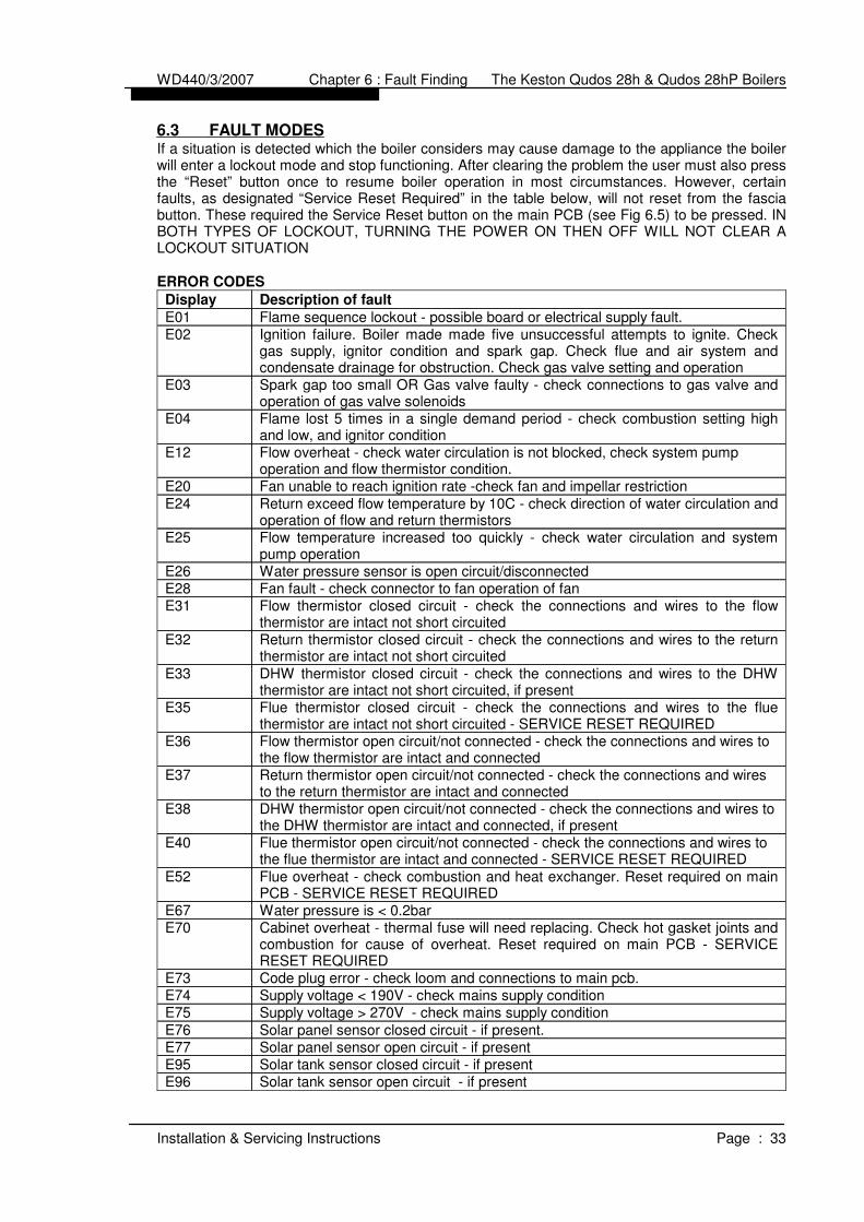
6.3 FAULT MODES
If a situation is detected which the boiler considers may cause damage to the appliance the boilerwill enter a lockout mode and stop functioning. After clearing the problem the user must also pressthe “Reset” button once to resume boiler operation in most circumstances. However, certainfaults, as designated “Service Reset Required” in the table below, will not reset from the fasciabutton. These required the Service Reset button on the main PCB (see Fig 6.5) to be pressed. INBOTH TYPES OF LOCKOUT, TURNING THE POWER ON THEN OFF WILL NOT CLEAR ALOCKOUT SITUATION
ERROR CODES
Solar tank sensor open circuit - if presentE96Solar tank sensor closed circuit - if presentE95Solar panel sensor open circuit - if presentE77 Solar panel sensor closed circuit - if present.E76
Supply voltage > 270V - check mains supply conditionE75Supply voltage < 190V - check mains supply conditionE74Code plug error - check loom and connections to main pcb.E73
Cabinet overheat - thermal fuse will need replacing. Check hot gasket joints andcombustion for cause of overheat. Reset required on main PCB - SERVICERESET REQUIRED
E70Water pressure is < 0.2barE67
Flue overheat - check combustion and heat exchanger. Reset required on mainPCB - SERVICE RESET REQUIRED
E52
Flue thermistor open circuit/not connected - check the connections and wires tothe flue thermistor are intact and connected - SERVICE RESET REQUIRED
E40
DHW thermistor open circuit/not connected - check the connections and wires tothe DHW thermistor are intact and connected, if present
E38
Return thermistor open circuit/not connected - check the connections and wiresto the return thermistor are intact and connected
E37
Flow thermistor open circuit/not connected - check the connections and wires tothe flow thermistor are intact and connected
E36
Flue thermistor closed circuit - check the connections and wires to the fluethermistor are intact not short circuited - SERVICE RESET REQUIRED
E35
DHW thermistor closed circuit - check the connections and wires to the DHWthermistor are intact not short circuited, if present
E33
Return thermistor closed circuit - check the connections and wires to the returnthermistor are intact not short circuited
E32
Flow thermistor closed circuit - check the connections and wires to the flowthermistor are intact not short circuited
E31Fan fault - check connector to fan operation of fanE28Water pressure sensor is open circuit/disconnectedE26
Flow temperature increased too quickly - check water circulation and systempump operation
E25
Return exceed flow temperature by 10C - check direction of water circulation andoperation of flow and return thermistors
E24
Fan unable to reach ignition rate -check fan and impellar restrictionE20
Flow overheat - check water circulation is not blocked, check system pumpoperation and flow thermistor condition.
E12
Flame lost 5 times in a single demand period - check combustion setting highand low, and ignitor condition
E04
Spark gap too small OR Gas valve faulty - check connections to gas valve andoperation of gas valve solenoids
E03
Ignition failure. Boiler made made five unsuccessful attempts to ignite. Checkgas supply, ignitor condition and spark gap. Check flue and air system andcondensate drainage for obstruction. Check gas valve setting and operation
E02Flame sequence lockout - possible board or electrical supply fault.E01
Description of faultDisplay
WD440/3/2007 Chapter 6 : Fault Finding The Keston Qudos 28h & Qudos 28hP Boilers
Installation & Servicing Instructions Page : 33

ERROR HISTORY
The Qudos 28h has an internal memory function that stores the last six errorsencountered along with the sensor readings at that time and the time elapsed betweeneach error occuring. This is very useful for diagnosing the cause of an error lockout,particularly when the error is intermittant.
Press the “” button repeatedly until the display shows “SHE” (“Show Errors”) and thenpress the “ENTER” button, you will enter the Error History mode. Press the “” button toshow the error number to investigate (Er1 is the most recent and Er6 is the oldest).Having selected the error press “ENTER”. Press the “” to scroll through the readingsstored at the time of the lockout occuring. The table below shows the values associatedwith consecutive “” button press:
Time in hours since last error occured9
Position in sequence:0 - Initialise; 1 - Standby; 4 - Purge; 6 - Safety; 7 - Run; 8 - Postpurge; 9- Inter-Purge; 12 - Lockout
8
Outside temperaure - display indicates a small graph on the bottom row. (NB: Onlyrelevant if an outside temperature sensor is detected)
7
System water pressure, in bar. (Minimum 0.2 bar. The boiler will shut down if thewater pressure drops below 0. bar)
6
Actual Flue Temperature - display indicates the flame and fan symbols (NB: Fluetemperatures above 75C may cause reduced boiler output. Flue temperaturesabove 80C will cause boiler lockout)
5
Actual DHW temperature - display indicates a tap symbol (NB Only relevant if theDHW sensor option is connected)
4
Actual CH return temperature (maximum 72C) - display indicates a radiator symboland a “2”. (NB Flow temperatures more than 20C above return temperature maylead to overheat and noise problems. Check the system pump performance andthe system for blockages)
3
Actual CH flow temperature (maximum 84C) - display indicates a radiator symboland a “1”
2The error code recorded for the lockoutEnn
MeaningSeq. No.
WD440/3/2007 Chapter 6 : Fault Finding The Keston Qudos 28h & Qudos 28hP Boilers
Installation & Servicing Instructions Page : 34

6.4 FUNCTIONAL FLOW WIRING DIAGRAM
WD440/3/2007 Chapter 6 : Fault Finding The Keston Qudos 28h & Qudos 28hP Boilers
Installation & Servicing Instructions Page : 35

6.5 ELECTRICAL WIRING DIAGRAM
WD440/3/2007 Chapter 6 : Fault Finding The Keston Qudos 28h & Qudos 28hP Boilers
Installation & Servicing Instructions Page : 36
Ω
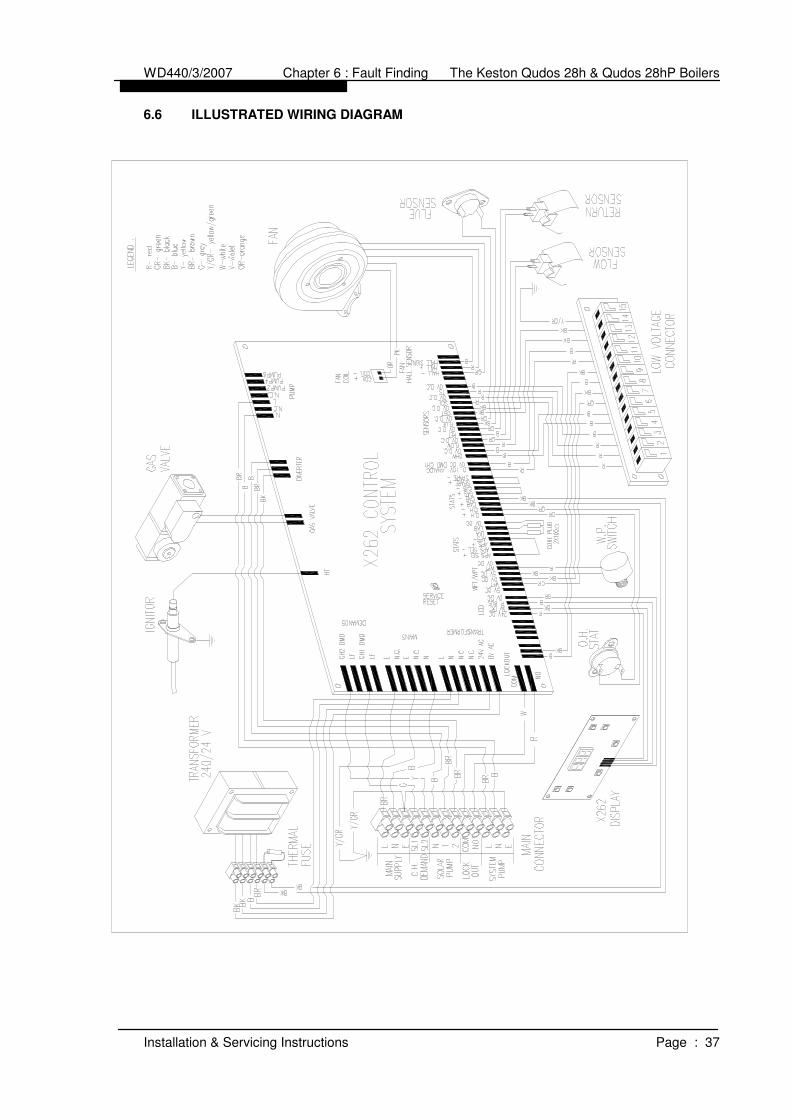
6.6 ILLUSTRATED WIRING DIAGRAM
WD440/3/2007 Chapter 6 : Fault Finding The Keston Qudos 28h & Qudos 28hP Boilers
Installation & Servicing Instructions Page : 37

6.7 Exploded Assembly Diagrams
6.7.1 Boiler Controls Assembly
WD440/3/2007 Chapter 6 : Fault Finding The Keston Qudos 28h & Qudos 28hP Boilers
Installation & Servicing Instructions Page : 38

6.7.2 Waterway, Condensate & Flue Assembly
WD440/3/2007 Chapter 6 : Fault Finding The Keston Qudos 28h & Qudos 28hP Boilers
Installation & Servicing Instructions Page : 39

6.7.3 Air - Gas Assembly
WD440/3/2007 Chapter 6 : Fault Finding The Keston Qudos 28h & Qudos 28hP Boilers
Installation & Servicing Instructions Page : 40

6.7.4 Casing Assembly
WD440/3/2007 Chapter 6 : Fault Finding The Keston Qudos 28h & Qudos 28hP Boilers
Installation & Servicing Instructions Page : 41
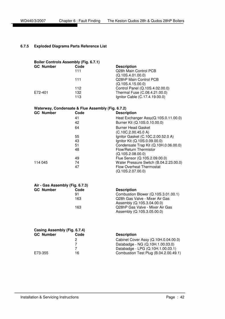
6.7.5 Exploded Diagrams Parts Reference List
Boiler Controls Assembly (Fig. 6.7.1)
GC Number Code Description
111 Q28h Main Control PCB(Q.10S.4.01.00.0)
111 Q28hP Main Control PCB(Q.10S.4.15.00.0)
112 Control Panel (Q.10S.4.02.00.0)E72-401 132 Thermal Fuse (C.08.4.21.00.0)
113 Ignitor Cable (C.17.4.19.00.0)
Waterway, Condensate & Flue Assembly (Fig. 6.7.2)
GC Number Code Description
41 Heat Exchanger Assy(Q.10S.0.11.00.0)
42 Burner Kit (Q.10S.0.10.00.0)
64 Burner Head Gasket
(C.10C.2.00.45.0 A)55 Ignitor Gasket (C.10C.2.00.52.0 A)43 Ignitor Kit (Q.10S.0.09.00.0)51 Condensate Trap Kit (Q.10H.0.06.00.0)48 Flow/Return Thermistor
(Q.10S.2.08.00.0)49 Flue Sensor (Q.10S.2.09.00.0)
114 045 74 Water Pressure Switch (B.04.2.23.00.0)47 Flow Overheat Thermostat
(Q.10S.2.07.00.0)
Air - Gas Assembly (Fig. 6.7.3)
GC Number Code Description
91 Combustion Blower (Q.10S.3.01.00.1)163 Q28h Gas Valve - Mixer Air Gas
Assembly (Q.10S.3.04.00.0)163 Q28hP Gas Valve - Mixer Air Gas
Assembly (Q.10S.3.05.00.0)
Casing Assembly (Fig. 6.7.4)
GC Number Code Description
2 Cabinet Cover Assy (Q.10H.0.04.00.0)
7 Databadge - NG (Q.10H.1.00.03.0)7 Databadge - LPG (Q.10H.1.00.03.1)
E73-355 16 Combustion Test Plug (B.04.2.00.49.1)
WD440/3/2007 Chapter 6 : Fault Finding The Keston Qudos 28h & Qudos 28hP Boilers
Installation & Servicing Instructions Page : 42

7. ROUTINE (ANNUAL) SERVICING
To ensure the continued safe and efficient operation of the boiler it is necessary to carry outroutine servicing at regular intervals. Servicing must be carried out at least once per year. Thefrequency of the servicing will depend upon the particular operating conditions.
It is the law that any service work must be carried out by competent qualified persons.
NB: When servicing ensure that the gas and electrical supplies to the boiler are isolated beforeany work starts.
Hazardous materials are not used in the construction of the Qudos 28h and Qudos 28hP.However, due care should be taken when handling boiler components.All joints should be checked for tightness after servicing and before firing the appliance.
After servicing complete the Gas Boiler Commissioning Checklist - Service Interval Record
(Chapter 10). These forms (Chapter 10) should be kept in a safe place for the life of the
boiler.
7.1 Pre-Service Checks
It is recommended that an inspection should be carried out prior to shutting down the unitfor servicing. Remove the front cover by removing the screws retaining the top andbottom. The following items should be observed:
a. Smooth starting and running of the blower.b. Smooth lighting of the burner.c. Check for leakage of gas, gas/air or combustion products.d. Check all flexible joints and hoses for condition and soundness - replace if
necessary e. Check for condensate leaks.f. Check for water soundness.g. Inspect the flue vent and air intake pipework. Joints must be sound and all
pipework well bracketed.h. Check that there is a steady fall back to the boiler from the flue pipe to allow
condensate to run back into the boiler.i. With the boiler operating at a low return temperature (i.e. less than 50oC) check
that the condensate flows freely from the condensate line.
7.2 Recommended Routine Service
a. Remove the outer case by first removing the securing screws at the top andbottom of the appliance.
b. Remove the burner head (Section 8.6) and inspect the burner appearance. Blackmarkings or other discoloration's on the gauze indicate too much gas or a lack ofair possibly due to a blocked air inlet. Any breakage's or damage to the burnermesh indicate the burner must be replaced.
c. If necessary clean the burner with a mild household detergent and rinse under ahot running tap.
d. If necessary, from visual inspection, clean the heat exchanger using a suitablestiff plastic bristle brush, vacuum out any large particles and flush the heatexchanger with fresh water until the water flowing from the condensate drain isclear.
e. Remove the condensate trap (Section 8.8) and clean by flushing through withclean running water.
f. Check the electrode assembly mounted on the heat exchanger. If the point isdamaged or burnt replace it.Check that the spark gap measures 4 mm.
WD440/3/2007 Chapter 7 : Servicing The Keston Qudos 28h & Qudos 28hP Boilers
Installation & Servicing Instructions Page : 43

g. Replace the burner head, inspecting the gasket for damage and replacing ifnecessary, and reconnect the gas/air supply. Ensure the flanged gas/air supplyjoint is air tight.
h. Turn on the electrical supply to the boiler and allow the boiler to reach operatingtemperature levels.
i. Remove the combustion test point plug from the flue pipe. This is situated on theflue spigot out of the cabinet.
j. Carry the full procedure detailed in section 5.7 COMBUSTION TESTING -MANDATORY
k. Replace the combustion test point plug.l. Recheck the burner pressure by following the procedure detailed in Section 4.7.
m. Check all joints for tightness up to the gas burner.
n. Complete the Gas Boiler Commissioning Checklist - Service Interval Record
(Chapter 10).
WD440/3/2007 Chapter 7 : Servicing The Keston Qudos 28h & Qudos 28hP Boilers
Installation & Servicing Instructions Page : 44

8. REPLACEMENT OF PARTS
CONTENTS
8.0 GENERAL8.1 PRECAUTIONS8.2 ACCESS8.3 REPLACEMENT PROCEDURE8.4 ELECTRICAL COMPONENTS
8.4.1 CONTROL PANEL8.4.2 BOILER FLOW & RETURN THERMISTORS8.4.3 CABINET TEMPERATURE SENSOR8.4.4 FLUE THERMISTOR8.4.5 WATER PRESSURE SWITCH8.4.6 MAIN CONTROL PCB8.4.7 COMBUSTION BLOWER8.4.8 GAS CONTROL VALVE8.4.9 FLOW THERMOSTAT
8.5 SPARK IGNITION/FLAME DETECTION ELECTRODE8.6 BURNER8.7 HEAT EXCHANGER8.8 CONDENSATE TRAP
8.0 GENERAL
The following must always be carried out by a competent/qualified person.
8.1 PRECAUTIONS
i) Always switch off the mains electricity supply and disconnect the plug at the isolatingswitch and socket. (If a switch only is used then remove the fuse.)
ii) Gain access to the appliance (Section 8.2) and turn off the gas supply at theappliance service cock.
WARNING : Parts of the boiler internal wiring will remain live even after setting the
User Controls to Standby. Shut off the power supply at the isolating
switch before working on the appliance.
8.2 ACCESS
i) Remove the cabinet by removing the screws to the top and bottom of the cabinet.
8.3 REPLACEMENT PROCEDURE
i) Always replace in the reverse order unless otherwise stated.ii) Electrical connections must be remade in accordance with the Electrical Wiring
Diagram (Section 6.5).iii) Test the tightness of any gas carrying or water carrying joint broken during the service
procedures.
8.4 ELECTRICAL COMPONENTS
8.4.1 Control Panel (Fig. 6.7.1 item 112)i) Isolate the appliance (Section 8.1)ii) Gain access (Section 8.2)iii) Remove the user control cover by removing the four retaining screws (Fig
6.7.1, item 125 and item 124).iv) Disconnect the Control Panel by unplugging the cable connector.v) Remove the Control Panel by removing the four retaining screws (Fig 6.7.1,
item 141).vi) Reassemble (Section 8.3)vii) Check for correct operation of the Control Panel.
WD440/3/2007 Chapter 8 : Replacement Of Parts The Keston Qudos 28h & Qudos 28hPBoilers
Installation & Servicing Instructions Page : 45
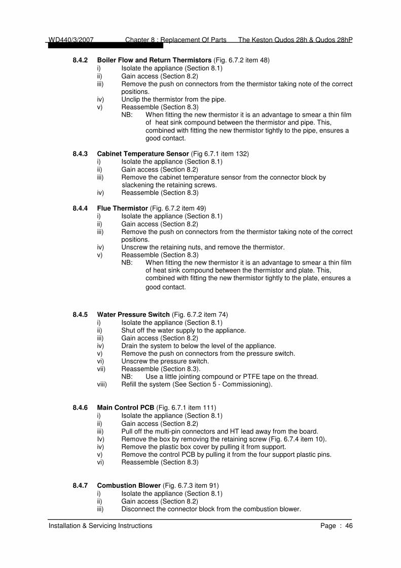
8.4.2 Boiler Flow and Return Thermistors (Fig. 6.7.2 item 48)i) Isolate the appliance (Section 8.1)ii) Gain access (Section 8.2)iii) Remove the push on connectors from the thermistor taking note of the correct
positions.iv) Unclip the thermistor from the pipe.v) Reassemble (Section 8.3)
NB: When fitting the new thermistor it is an advantage to smear a thin filmof heat sink compound between the thermistor and pipe. This,combined with fitting the new thermistor tightly to the pipe, ensures agood contact.
8.4.3 Cabinet Temperature Sensor (Fig 6.7.1 item 132)i) Isolate the appliance (Section 8.1)ii) Gain access (Section 8.2)iii) Remove the cabinet temperature sensor from the connector block by
slackening the retaining screws.iv) Reassemble (Section 8.3)
8.4.4 Flue Thermistor (Fig. 6.7.2 item 49)i) Isolate the appliance (Section 8.1)ii) Gain access (Section 8.2)iii) Remove the push on connectors from the thermistor taking note of the correct
positions.iv) Unscrew the retaining nuts, and remove the thermistor.v) Reassemble (Section 8.3)
NB: When fitting the new thermistor it is an advantage to smear a thin filmof heat sink compound between the thermistor and plate. This,combined with fitting the new thermistor tightly to the plate, ensures a
good contact.
8.4.5 Water Pressure Switch (Fig. 6.7.2 item 74)i) Isolate the appliance (Section 8.1)ii) Shut off the water supply to the appliance.iii) Gain access (Section 8.2)iv) Drain the system to below the level of the appliance.v) Remove the push on connectors from the pressure switch.vi) Unscrew the pressure switch.vii) Reassemble (Section 8.3).
NB: Use a little jointing compound or PTFE tape on the thread.viii) Refill the system (See Section 5 - Commissioning).
8.4.6 Main Control PCB (Fig. 6.7.1 item 111)i) Isolate the appliance (Section 8.1)ii) Gain access (Section 8.2)iii) Pull off the multi-pin connectors and HT lead away from the board.Iv) Remove the box by removing the retaining screw (Fig. 6.7.4 item 10).iv) Remove the plastic box cover by pulling it from support.v) Remove the control PCB by pulling it from the four support plastic pins.vi) Reassemble (Section 8.3)
8.4.7 Combustion Blower (Fig. 6.7.3 item 91)i) Isolate the appliance (Section 8.1)ii) Gain access (Section 8.2)iii) Disconnect the connector block from the combustion blower.
WD440/3/2007 Chapter 8 : Replacement Of Parts The Keston Qudos 28h & Qudos 28hPBoilers
Installation & Servicing Instructions Page : 46

iv) Unscrew the bolts (Fig 6.7.3 item 94) securing the gas inlet pipe to the gascontrol valve.
v) Remove the four nuts securing the combustion blower (fig. 6.7.3 item 100)outlet flange to the burner and remove the combustion blower.
vi) Reassemble (Section 8.3)NB: When reassembling inspect any gaskets for damage and replace if
necessary.
8.4.8 Gas Control Valve /Venturi Assembly (Fig. 6.7.3 item 163)i) Isolate the appliance (Section 8.1)ii) Gain access (Section 8.2)iii) Remove the push on connector block to the gas valve.iv) Unscrew the bolts (Fig 6.7.3 item 94) securing the gas inlet pipe to the gas
control valve.v) Unscrew the bolts securing the gas valve (Fig 6.7.3 item 106) to the inlet port
of the combustion blower.vi) Remove the gas valve/venturi assembly as a complete unit.vii) Unscrewing the union fitting from the gas valve.viii) Reassemble (Section 8.3)ix) Check the gas rate and combustion (See Section 5 - Commissioning)
NB: Always change the gas valve/venturi assembly together. This assembly is factory preset but must be checked using the procedure set out in Section 5.7 (Combustion testing).
8.4.9 Flow Overheat Thermostat (Fig. 6.7.2 item 47)i) Isolate the appliance (Section 8.1)ii) Gain access (Section 8.2)iii) Remove the push on connector from the sensor taking note of the correct
position.iv) Unscrew the bolts securing the stat (Fig 6.7.2 item 60)v) Reassemble (Section 8.3)
NB: When fitting the new thermostat it is an advantage to smear a thin film of heat sink compound between the thermistor and pipe. This, combined with fitting the new thermistor tightly to the pipe, ensures a good contact.
8.5 SPARK IGNITION/FLAME DETECTION ELECTRODE (Fig. 6.7.2 item 43)i) Isolate the appliance (Section 8.1)ii) Gain access (Section 8.2)iii) Remove the pull off HT lead to the spark ignition electrode.iv) Undo the screws to the spark ignition electrode flange located on the heat exchanger
top panel (Fig 6.7.2 item 56) and withdraw the spark ignition electrode.
v) Reassemble (Section 8.3)NB: When reassembling inspect the gasket for damage and replace if necessary.
With the new spark ignition electrode in place it is essential to ensure the gapbetween the tip of the electrode and the burner surface is 4 mm. Distancesabove or below 4 mm will affect ignition performance. If necessary gently
bend the electrode taking care not to damage the ceramic insulator. 8.6 BURNER (Fig. 6.7.2 items 42)
i) Isolate the appliance (Section 8.1)ii) Gain access (Section 8.2)iii) Remove the combustion blower (Section 8.4.7)iv) Remove the 4 nuts fixing the burner to the top of the heat exchanger (Fig 6.7.3, item
100).v) Remove the spark ignition/flame detection electrode (Section 8.5)vi) Withdraw the burner from the top of the heat exchanger.vii) Reassemble (Section 8.3)
NB: When reassembling inspect any gaskets for damage and replace ifnecessary.
WD440/3/2007 Chapter 8 : Replacement Of Parts The Keston Qudos 28h & Qudos 28hPBoilers
Installation & Servicing Instructions Page : 47

8.7 HEAT EXCHANGER (Fig. 6.7.2 item 41)i) Isolate the appliance (Section 8.1)ii) Gain access (Section 8.2)iii) Shut off the water supply to the appliance.iv) Remove the burner (Section 8.6)v) Drain the system to below the level of the appliance. vi) Remove the flue thermistor (Section 8.4.4)vii) Remove the spark ignition/flame detection electrode (Section 8.5)viii) Remove the flue connection by slackening the retaining strap and pulling the flue off
the heat exchanger spigot.ix) Remove the condensate trap (Section 8.8)x) Disconnect the flow and return pipe union nuts (Fig 6.7.2 item 68) from the heat
exchanger.xi) Remove the two screws (Fig. 6.7.2 item 66) fixing the heat exchanger to the top.xii) Remove the heat exchangerxiii) Reassemble (Section 8.3)xiv) Recommission (Section 5 - Commissioning)
8.8 CONDENSATE TRAP (Fig. 6.7.2 item 51)i) Isolate the appliance (Section 8.1)ii) Gain access (Section 8.2)
Remove the two screws and washers (Fig. 6.7.2 items 76 and 77) fixing thecondensate trap to the base of the cabinet.
iii) Disconnect the condense line from the projection of the condensate trap from thebase of the cabinet.
iv) Withdraw the condensate trap.v) Mop up any spilled condensate.vi) Reassemble (Section 8.3)
NB: When reassembling inspect the oring (Fig 6.7.2 item 73) for damage andreplace if necessary. When re-fitting the condensate trap pour water untilnearly full. Then reconnect the condensate trap to the base of the heatexchanger.
WD440/3/2007 Chapter 8 : Replacement Of Parts The Keston Qudos 28h & Qudos 28hPBoilers
Installation & Servicing Instructions Page : 48

9. SHORT SPARE PARTS LIST
Item GC No Part Denomination Item GC No PartDenomination
42 Burner KIT 64 Burner Gasket
55 Ignitor Gasket 43 Ignitor KIT
48 Flow/Return Thermistors 49 Flue Thermistor
47 Flow Overheat Thermostat 74 Water Press. Switch
WD440/3/2007 Chapter 9 : Spare Parts Listings The Keston Qudos 28h & Qudos 28hP Boilers
Installation & Servicing Instructions Page: 49

163 Q28h Gas Valve - Mixer Assem. 91 Fan
Q28hP Gas Valve - Mixer Assem.
112 Control Panel 111 Q28h Control PCB Q28hP Con. PCB
WD440/3/2007 Chapter 9 : Spare Parts Listings The Keston Qudos 28h & Qudos 28hP Boilers
Installation & Servicing Instructions Page: 50

SHORT SPARE PARTS LIST FOR THE KESTON
CONDENSING BOILER RANGE
Item GC No Part Denomination
42 Burner KIT64 Burner Gasket43 Ignitor KIT55 Ignitor Gasket48 Flow/Return Thermistor49 Flue Thermistor47 Flow Thermostat74 Water Pressure Switch91 Fan163 Gas Valve - Mixer Air-Gas Assembly
(NG-Q28s)163 Gas Valve - Mixer Air-Gas Assembly
(LPG-Q28sP)112 Control Panel111 Control PCB (NG-Q28h)111 Control PCB (LPG-Q28hP)
WD440/3/2007 Chapter 9 : Spare Parts Listings The Keston Qudos 28h & Qudos 28hP Boilers
Installation & Servicing Instructions Page: 51

WD440/3/2007 Chapter 10 : Benchmark Checklist Final The Keston Qudos 28h & Qudos 28hP Boilers
Installation & Servicing Instructions Page : 52
10. GAS BOILER COMMISSIONING CHECKLIST
BENCHMARK No.
GAS BOILER COMMISSIONING CHECKLIST
BOILER SERIAL No. ___________________ NOTIFICATION No. ____________________
CONTROLS To comply with the Building Regulation, each section must have a tick in one or other of the boxes
TIME & TEMPERATURE CONTROL TO
HEATING
ROOM T/STAT &
PROGRAMMER/TIMER PROGRAMMABLE ROOMSTAT
TIME & TEMPERATURE CONTROL TO HOT
WATER
CYLINDER T/STAT &
PROGRAMMER/TIMER COMBI BOILER
HEATING ZONE VALVES FITTED NOT REQUIRED
HOT WATER ZONE VALVES FITTED NOT REQUIRED
THERMOSTATIC RADIATOR VALVES FITTED
AUTOMATIC BYPASS TO SYSTEM FITTED NOT REQUIRED
FOR ALL BOILERS CONFIRM THE FOLLOWING
THE SYSTEM HAS BEEN FLUSHED IN ACCORDANCE WITH THE BOILER MANUFACTURER’S INSTRUCTIONS ?
THE SYSTEM CLEANER USED
THE INHIBITOR USED
FOR THE CENTRAL HEATING MODE, MEASURE & RECORD
GAS RATE m3/hr ft3/hr
BURNER OPERATING PRESSURE (IF APPLICABLE) N/A mbar
CENTRAL HEATING FLOW TEMPERATURE OC
CENTRAL HEATING RETURN TEMPERATURE OC
FOR COMBINATION BOILERS ONLY
HAS A WATER SCALE REDUCER BEEN FITTED ? YES NO
WHAT TYPE OF SCALE REDUCER HAS BEEN FITTED ?
FOR THE DOMESTIC HOT WATER MODE, MEASURE & RECORD
GAS RATE m3/hr ft3/hr
MAXIMUM BURNER OPERATING PRESSURE (IF APPLICABLE) N/A mbar
COLD WATER INLET TEMPERATURE OC
HOT WATER OUTLET TEMPERATURE OC
WATER FLOW RATE lts/min
FOR CONDENSING BOILERS ONLY CONFIRM THE FOLLOWING
THE CONDENSATE DRAIN HAS BEEN INSTALLED IN ACCORDANCE WITH
THE MANUFACTURER’S INSTRUCTIONS ? YES
FOR ALL INSTALLATIONS CONFIRM THE FOLLOWING
THE HEATING AND HOT WATER SYSTEM COMPLIES
WITH CURRENT BUIDING REGULATIONS
THE APPLIANCE AND ASSOCIATED EQUIPMENT HAS BEEN INSTALLED AND COMISSIONED
IN ACCORDANCE WITH THE MANUFACTURER’S INSTRUCTIONS
IF REQUIRED BY THE MANUFACTURER, HAVE YOU RECORDE A CO/CO2 RATIO READING? N/A YES CO/CO2
RATIO
THE OPERATION OF THE APPLIANCE AND SYSTEM
CONTROLS HAVE BEEN DEMONSTRATED TO THE CUSTOMER
THE MANUFACTURER’S LITERATURE HAS BEEN LEFT WITH THE CUSTOMER

WD440/3/2007 Chapter 10 : Benchmark Checklist Final The Keston Qudos 28h & Qudos 28hP Boilers
Installation & Servicing Instructions Page : 53
SERVICE INTERVAL RECORD
It is recommended that your heating system is serviced regularly
and that you complete the appropriate Service Interval Record Below Service Provider. Before completing the appropriate Service Interval Record below, please ensure you have carried out the service
as described in the boiler manufacturer’s instructions. Always use the manufacturer’s specified spare part when replacing all controls
SERVICE 2 DATE
ENGINEER NAME
COMPANY NAME
TEL No.
CORGI ID CARD SERIAL No.
COMMENTS
SIGNATURE
SERVICE 1 DATE
ENGINEER NAME
COMPANY NAME
TEL No.
CORGI ID CARD SERIAL No.
COMMENTS
SIGNATURE
SERVICE 3 DATE
ENGINEER NAME
COMPANY NAME
TEL No.
CORGI ID CARD SERIAL No.
COMMENTS
SIGNATURE
SERVICE 4 DATE
ENGINEER NAME
COMPANY NAME
TEL No.
CORGI ID CARD SERIAL No.
COMMENTS
SIGNATURE
SERVICE 6 DATE
ENGINEER NAME
COMPANY NAME
TEL No.
CORGI ID CARD SERIAL No.
COMMENTS
SIGNATURE
SERVICE 5 DATE
ENGINEER NAME
COMPANY NAME
TEL No.
CORGI ID CARD SERIAL No.
COMMENTS
SIGNATURE
SERVICE 7 DATE
ENGINEER NAME
COMPANY NAME
TEL No.
CORGI ID CARD SERIAL No.
COMMENTS
SIGNATURE
SERVICE 8 DATE
ENGINEER NAME
COMPANY NAME
TEL No.
CORGI ID CARD SERIAL No.
COMMENTS
SIGNATURE
SERVICE 9 DATE
ENGINEER NAME
COMPANY NAME
TEL No.
CORGI ID CARD SERIAL No.
COMMENTS
SIGNATURE
SERVICE 10 DATE
ENGINEER NAME
COMPANY NAME
TEL No.
CORGI ID CARD SERIAL No.
COMMENTS
SIGNATURE

† Read Installation Manual Carefully
† Ensure that ALL dust particles, filings , plastic chips etc. are
removed from the inlet pipe.
† If the installation is a replacement the system must be flushed
clean. System should be drained hot, then refilled, then drainedagain until the water is clean.
† Ensure that there is a proper electrical supply i.e. 230V fused at
3A for the permanent live.
† Ensure that the system pump is wired back to the System Pump
connections in the boiler
† Take great care with pipe connections to ensure that no
damage is done to the internal pipework.
† Ensure that the 22mm condensate pipe is not exposed to
freezing conditions.
† Make sure that the exhaust pipe terminates away from windows
or vents and is out of reach.
† Make sure that the air inlet and exhaust pipe outlets are at least
200mm apart.
† Check tightness of all connections in the boiler before firing.
† Ensure that the terminals supplied are fitted to both the exhaust
and air inlet pipes.
† The system must be free from air before firing.
† If TRV's are installed on radiators ensure that a bypass is
installed to maintain required flow.
† Complete the Gas Boiler Commissioning Checklist - Service
Interval Record (Chapter 10).
† Complete the combustion testing (Section 5.7) using a
calibrated flue gas analyser.
WD441/1/2008
KESTON CONDENSING BOILERS
IMPORTANT
Qudos 28h and Qudos 28hP INSTALLATION KEY POINTS
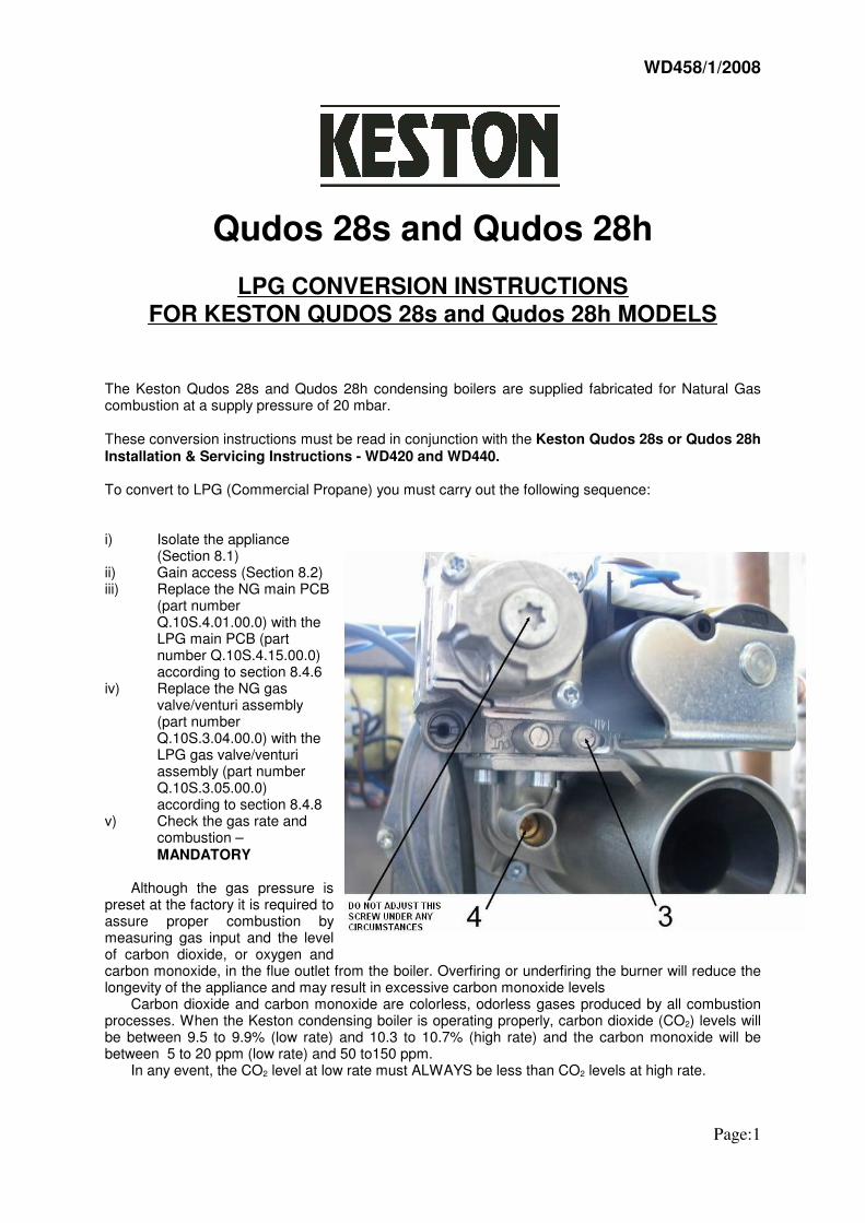
Qudos 28s and Qudos 28h
LPG CONVERSION INSTRUCTIONS
FOR KESTON QUDOS 28s and Qudos 28h MODELS
The Keston Qudos 28s and Qudos 28h condensing boilers are supplied fabricated for Natural Gascombustion at a supply pressure of 20 mbar.
These conversion instructions must be read in conjunction with the Keston Qudos 28s or Qudos 28h
Installation & Servicing Instructions - WD420 and WD440.
To convert to LPG (Commercial Propane) you must carry out the following sequence:
i) Isolate the appliance(Section 8.1)
ii) Gain access (Section 8.2)iii) Replace the NG main PCB
(part numberQ.10S.4.01.00.0) with theLPG main PCB (partnumber Q.10S.4.15.00.0)according to section 8.4.6
iv) Replace the NG gasvalve/venturi assembly(part numberQ.10S.3.04.00.0) with theLPG gas valve/venturiassembly (part numberQ.10S.3.05.00.0)according to section 8.4.8
v) Check the gas rate andcombustion –MANDATORY
Although the gas pressure ispreset at the factory it is required toassure proper combustion bymeasuring gas input and the levelof carbon dioxide, or oxygen andcarbon monoxide, in the flue outlet from the boiler. Overfiring or underfiring the burner will reduce thelongevity of the appliance and may result in excessive carbon monoxide levels
Carbon dioxide and carbon monoxide are colorless, odorless gases produced by all combustionprocesses. When the Keston condensing boiler is operating properly, carbon dioxide (CO2) levels willbe between 9.5 to 9.9% (low rate) and 10.3 to 10.7% (high rate) and the carbon monoxide will bebetween 5 to 20 ppm (low rate) and 50 to150 ppm.
In any event, the CO2 level at low rate must ALWAYS be less than CO2 levels at high rate.
WD458/1/2008
Page:1
To measure CO2 levels in the Keston boiler remove the 1/8" plug from the flue outlet pipe spigot(Figure 6.7.4 item 17). Insert the probe of a calibrated combustion analysis meter and sample thegases as instructed in the test equipment's instructions.
When firing the boiler for the first time since installation, the CO level at high rate may be between100 & 220 ppm and between 50 & 80 ppm at low rate. This is due to compounds used duringmanufacture curing within the combustion chamber. On boilers which have been fired for more thanone hour since installation, the CO levels should not exceed 150 ppm at high rate and 50 ppm at lowrate. If CO levels above these values are experienced, the combustion chamber and flue systemshould be investigated.
The Qudos 28s is factory set for combustion and should need no adjustment. However, in theevent adjustment is required.
Check combustion errors are not a result of incorrectly installed flue and/or air system, terminallocation or damage or debris on the burner. If all these factors are found to be in order precede asfollows:
1) Set any controls to call for heat.2) Press the “” button repeatedly until the display shows “SEr”, then press “ENTER”. Press
the “” until the display shows “100%”. Press “ENTER” and the boiler will be locked on at Maximumrate. If no further buttons are pressed for 10 minutes the boiler will automatically revert to normaloperation.
3) Measure the CO2 reading in the flue gases and adjust, if necessary, the adjustment screw(pos 4) to produce a CO2 reading of 10.3 - 10.7% with a corresponding CO level of 50 - 150 ppm.
4) Press the “RESET” button once and then press the “ENTER” button. Use the “” button untilthe display shows “32%” (“30%” for LPG). Press the “ENTER” button and the boiler will be locked onat Minimum rate. If no further buttons are pressed for 10 minutes the boiler will automatically revert tonormal operation.
5) Measure the CO2 reading in the flue gases. The CO2 reading must be 8.4% to 8.8% with acorresponding CO level of 5 to 20 ppm for natural gas and 9.5% to 9.9% with a corresponding COlevel of 5 to 20 ppm for for LPG. THE CO2 LEVEL AT LOW RATE MUST ALWAYS BE LESS THANTHE CO2 LEVEL AT HIGH RATE.
6) Press the “RESET” button once and then use the “” button until the display shows “100%”.Press the “ENTER” button and the boiler will be locked on at Maximum rate. Check the setting iswithin the range established in step 3. If not, repeat the process again from step 3.
If following the above procedure, combustion levels described above at both high and
low rate could not be obtained, please turn off the appliance and isolate the gas to the appli-
ance. Telephone KESTON BOILERS technical support (phone no. 0208 462 0262)
8) Press the “RESET” button twice to return to the normal operation mode and display.
vi) Note the original appliance serial number band production date on the new data badgevii) Stick the new data badge Q.10S.1.00.04.1 ( for the Qudos 28sP - Fig. 6.7.4 item 8) or
Q.10H.1.00.03.1 (for the Qudos 28hP - Fig. 6.7.4 item 7) into the appliance in place of theoriginal NG database.
viii) Reassemble (Section 8.3).
Keston Condensing Boilers LPG Specifications
Supply pressure:
High 45 mbarNormal 37 mbarLow 25 mbar
WD458/1/2008
Page:2

Qudos 28sP and Qudos 28hP
NG CONVERSION INSTRUCTIONS
FOR KESTON QUDOS 28sP and Qudos 28hP MODELS
The Keston Qudos 28sP and Qudos 28hP condensing boilers are supplied fabricated for LPGcombustion at a supply pressure of 37 mbar.
These conversion instructions must be read in conjunction with the Keston Qudos 28s or Qudos 28h
Installation & Servicing Instructions - WD420 and WD440.
To convert to NG (natural gas) you must carry out the following sequence:
i) Isolate the appliance(Section 8.1)
ii) Gain access (Section 8.2)iii) Replace the LPG main
PCB (part numberQ.10S.4.15.00.0) with theNG main PCB (partnumber Q.10S.4.01.00.0)according to section 8.4.6
iv) Replace the LPG gasvalve/venturi assembly(part numberQ.10S.3.05.00.0) with theNG gas valve/venturiassembly (part numberQ.10S.3.04.00.0)according to section 8.4.8
v) Check the gas rate andcombustion –MANDATORY
Although the gas pressure ispreset at the factory it is required toassure proper combustion bymeasuring gas input and the levelof carbon dioxide, or oxygen andcarbon monoxide, in the flue outlet from the boiler. Overfiring or underfiring the burner will reduce thelongevity of the appliance and may result in excessive carbon monoxide levels
Carbon dioxide and carbon monoxide are colorless, odorless gases produced by all combustionprocesses. When the Keston condensing boiler is operating properly, carbon dioxide (CO2) levels willbe between 8.4 to 8.8% (low rate) and 8.9 to 9.3% (high rate) and the carbon monoxide will bebetween 5 to 20 ppm (low rate) and 50 to150 ppm.
In any event, the CO2 level at low rate must ALWAYS be less than CO2 levels at high rate.
WD480/0/2008
Page:1

To measure CO2 levels in the Keston boiler remove the 1/8" plug from the flue outlet pipe spigot(Figure 6.7.4 item 17). Insert the probe of a calibrated combustion analysis meter and sample thegases as instructed in the test equipment's instructions.
When firing the boiler for the first time since installation, the CO level at high rate may be between100 & 220 ppm and between 50 & 80 ppm at low rate. This is due to compounds used duringmanufacture curing within the combustion chamber. On boilers which have been fired for more thanone hour since installation, the CO levels should not exceed 150 ppm at high rate and 50 ppm at lowrate. If CO levels above these values are experienced, the combustion chamber and flue systemshould be investigated.
The Qudos 28s is factory set for combustion and should need no adjustment. However, in theevent adjustment is required.
Check combustion errors are not a result of incorrectly installed flue and/or air system, terminallocation or damage or debris on the burner. If all these factors are found to be in order precede asfollows:
1) Set any controls to call for heat.2) Press the “” button repeatedly until the display shows “SEr”, then press “ENTER”. Press
the “” until the display shows “100%”. Press “ENTER” and the boiler will be locked on at Maximumrate. If no further buttons are pressed for 10 minutes the boiler will automatically revert to normaloperation.
3) Measure the CO2 reading in the flue gases and adjust, if necessary, the adjustment screw(pos 4) to produce a CO2 reading of 8.9 - 9.3% with a corresponding CO level of 50 - 150 ppm.
4) Press the “RESET” button once and then press the “ENTER” button. Use the “” button untilthe display shows “32%”. Press the “ENTER” button and the boiler will be locked on at Minimum rate.If no further buttons are pressed for 10 minutes the boiler will automatically revert to normal operation.
5) Measure the CO2 reading in the flue gases. The CO2 reading must be 8.4% to 8.8% with acorresponding CO level of 5 to 20 ppm for natural gas. THE CO2 LEVEL AT LOW RATE MUSTALWAYS BE LESS THAN THE CO2 LEVEL AT HIGH RATE.
6) Press the “RESET” button once and then use the “” button until the display shows “100%”.Press the “ENTER” button and the boiler will be locked on at Maximum rate. Check the setting iswithin the range established in step 3. If not, repeat the process again from step 3.
If following the above procedure, combustion levels described above at both high and
low rate could not be obtained, please turn off the appliance and isolate the gas to the appli-
ance. Telephone KESTON BOILERS technical support (phone no. 0208 462 0262)
8) Press the “RESET” button twice to return to the normal operation mode and display.
vi) Note the original appliance serial number band production date on the new data badgevii) Stick the new data badge Q.10S.1.00.04.0 ( for the Qudos 28s - Fig. 6.7.4 item 8) or
Q.10H.1.00.03.0 (for the Qudos 28h - Fig. 6.7.4 item 7) into the appliance in place of theoriginal NG database.
viii) Reassemble (Section 8.3).
Keston Condensing Boilers NG Specifications
Supply pressure:
High 25 mbarNormal 20 mbarLow 17 mbar
WD480/0/2008
Page:2

WD478/0/2008
1/2
Qudos 28s and Qudos 28h
Gas valve/Venturi assembly replacement procedure for
KESTON Q28s, Q28sP, Q28h and Q28hP boilers.
These conversion instructions must be read in conjunction with the Keston Qudos 28s/28sP or Qudos
28h/Q28hP Installation & Servicing Instructions - WD420 and WD440. Before proceeding to the replacement procedure please check if the tamper paint on the offset adjustment cap (see attached picture) is intact. If the tamper paint is broken please return the assembly to KESTON BOILERS. Do not dismantle the gas valve/venturi assembly. Always change the gas valve/venturi assembly together. To replace the gas valve/venturi assembly you must carry out the following sequence:
1. Isolate the appliance (Section 8.1) 2. Gain access (Section 8.2) 3. Remove the push on connector block to the gas valve. 4. Unscrew the bolts (Fig 6.7.3 item 114) securing the gas inlet pipe to the gas control valve. 5. Unscrew the bolts securing the venturi (Fig 6.7.3 item 122) to the inlet port of the combustion blower. 6. Remove the gas valve/venturi assembly. 7. Unscrewing the union fitting from the gas valve. 8. Reassemble (Section 8.3) 9. Check the gas rate and combustion – MANDATORY Although the gas pressure is preset at the factory it is required to assure proper combustion by measuring
gas input and the level of carbon dioxide, or oxygen and carbon monoxide, in the flue outlet from the boiler. Over firing or under firing the burner will reduce the longevity of the appliance and may result in excessive carbon monoxide levels
Carbon dioxide and carbon monoxide are colorless, odorless gases produced by all combustion processes. When the Keston condensing boiler is operating properly, carbon dioxide (CO2) levels will be between 8.4 & 8.8% (low rate) and 8.9 & 9.3% (high rate) and carbon monoxide (CO) levels will be between 5 & 20 ppm (low rate) and 50 &150 ppm (high rate) for natural gas. For LP gas, carbon dioxide (CO2) levels will be between 9.5 to 9.9% (low rate) and 10.3 to 10.7% (high rate) and the carbon monoxide will be between 5 to 20 ppm (low rate) and 50 to150 ppm.
In any event, the CO2 level at low rate must ALWAYS be less than CO2 levels at high rate. To measure CO2 levels in the Keston boiler remove the 1/8" plug from the flue outlet pipe spigot (Figure
6.7.4 item 17). Insert the probe of a calibrated combustion analysis meter and sample the gases as instructed in the test equipment's instructions.
When firing the boiler for the first time since installation, the CO level at high rate may be between 100 & 220 ppm and between 50 & 80 ppm at low rate. This is due to compounds used during manufacture curing within the combustion chamber. On boilers which have been fired for more than one hour since installation, the CO levels should not exceed 150 ppm at high rate and 50 ppm at low rate. If CO levels above these values are experienced, the combustion chamber and flue system should be investigated.
The Qudos 28s is factory set for combustion and should need no adjustment. However, in the event adjustment is required.
Check combustion errors are not a result of incorrectly installed flue and/or air system, terminal location or damage or debris on the burner. If all these factors are found to be in order precede as follows:
1) Set any controls to call for heat.

WD478/0/2008
2/2
2) Press the “” button repeatedly until the display shows “SEr”, then press “ENTER”. Press the “” until the display shows “100%”. Press “ENTER” and the boiler will be locked on at Maximum rate. If no further buttons are pressed for 10 minutes the boiler will automatically revert to normal operation.
3) Measure the CO2 reading in the flue gases and adjust, if necessary, the adjustment screw (pos 4) to produce a CO2 reading of 8.9% - 9.3% with a corresponding CO level of 50 - 150 ppm for natural gas and 10.3 - 10.7% with a corresponding CO level of 50 - 150 ppm for LPG. NORMAL ADJUSTMENT, IF REQUIRED, SHOULD NEED NO MORE THAN HALF OF ONE ROTATION OF THE ADJUSTMENT SCREW (pos. 4).
4) Press the “RESET” button once and then press the “ENTER” button. Use the “” button until the display shows “32%” (“30%” for LPG). Press the “ENTER” button and the boiler will be locked on at Minimum rate. If no further buttons are pressed for 10 minutes the boiler will automatically revert to normal operation.
5) Measure the CO2 reading in the flue gases. The CO2 reading must be 8.4% to 8.8% with a corresponding CO level of 5 to 20 ppm for natural gas and 9.5% to 9.9% with a corresponding CO level of 5 to 20 ppm for LPG. THE CO2 LEVEL AT LOW RATE MUST ALWAYS BE LESS THAN THE CO2 LEVEL AT HIGH RATE.
6) Press the “RESET” button once and then use the “” button until the display shows “100%”. Press the “ENTER” button and the boiler will be locked on at Maximum rate. Check the setting is within the range established in step 3. If not, repeat the process again from step 3.
If following the above procedure, combustion levels described above at both high and low rate
could not be obtained, please turn off the appliance and isolate the gas to the appliance. Telephone
KESTON BOILERS technical support (phone no. 0208 462 0262)
8) Press the “RESET” button twice to return to the normal operation mode and display.