
Worcester Controls CPT Series Characterized Seat Control Valve ...

Worcester Controls PB 941-6
ACCESS™ ActuatorPneumatic automation
with total process interface
An ISO 9001 Registered Company

2 PB 941-6
Flow Control Division
Worcester Controls
Worcester Controls Introduces an Innovative Breakthrough To Users of Pneumatically Automated Valves
ACCESS™
The ACCESS package combines the field-proven 39 Series pneumatic actuator with integral limitswitches, proximity sensors, solenoid and optional digital protocol communications. This packageeliminates the need for additional enclosures, couplings, tubing, mounting brackets and associatedmultiple vendor involvement.
High-cycle, rack-and-pinionactuator with guide rodsupported pistons tomaximize performance life
ISO 5211 mounting pattern
Single electrical connectionMechanical or proximityposition sensors
Namur (VDI/VDE) Mounting PatternPosition Indicator
High-flow spool valvewith manual overrideand speed controls
LEDs for visualdiagnostics
Aluminum multi-ratedenclosures with eitheraluminum or Lexan®
covers to suit yourrequirements
Multipleprotocolcompatibility
Low-wattage,high-cyclesolenoid
PB 941-6 3
Flow Control Division
Worcester Controls
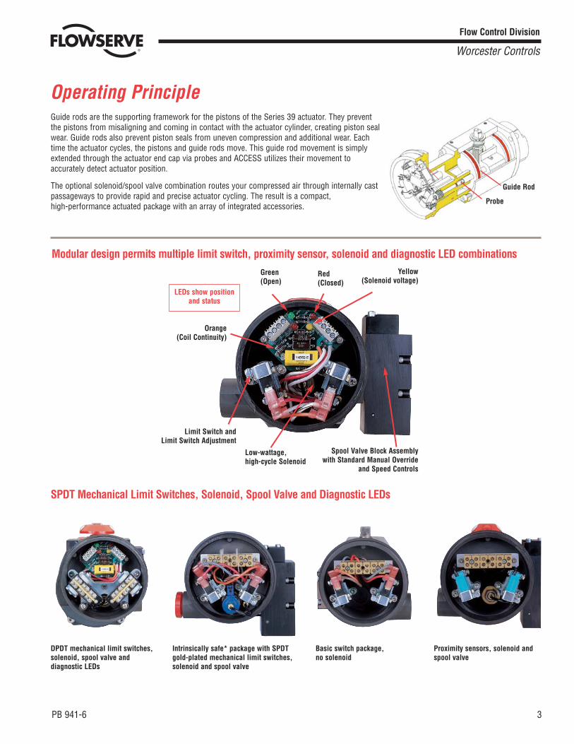
Operating PrincipleGuide rods are the supporting framework for the pistons of the Series 39 actuator. They preventthe pistons from misaligning and coming in contact with the actuator cylinder, creating piston sealwear. Guide rods also prevent piston seals from uneven compression and additional wear. Eachtime the actuator cycles, the pistons and guide rods move. This guide rod movement is simplyextended through the actuator end cap via probes and ACCESS utilizes their movement toaccurately detect actuator position.
The optional solenoid/spool valve combination routes your compressed air through internally castpassageways to provide rapid and precise actuator cycling. The result is a compact,high-performance actuated package with an array of integrated accessories.
Guide Rod
Probe
Modular design permits multiple limit switch, proximity sensor, solenoid and diagnostic LED combinations
Orange(Coil Continuity)
Green(Open)
Red(Closed)
Yellow(Solenoid voltage)
Spool Valve Block Assemblywith Standard Manual Override
and Speed Controls
Limit Switch andLimit Switch Adjustment
Low-wattage,high-cycle Solenoid
LEDs show positionand status
SPDT Mechanical Limit Switches, Solenoid, Spool Valve and Diagnostic LEDs
Intrinsically safe* package with SPDTgold-plated mechanical limit switches,solenoid and spool valve
Basic switch package, no solenoid
Proximity sensors, solenoid andspool valve
DPDT mechanical limit switches,solenoid, spool valve anddiagnostic LEDs

4 PB 941-6
Flow Control Division
Worcester Controls
Options
Lexan Weatherproof (W) Cover
Solenoid/Spool Valve No Solenoid
ACCESS I Integral Unit ACCESS M Mounted Unit
Aluminum Hazardous Environment (Z) Cover
TYPE 4, 4x
TYPE 4, 4x, 7, 9, 12 (Class 1, Division 1, Groups B, C and D)
If no solenoid is specified, a connection block permits directnipple mounting of an external solenoid or a tubingconnection from a remote solenoid.
When an integral solenoid isspecified, it is accompanied by ahigh-flow spool valve to providerapid, adjustable cycle times and astandard manual override.
Actuator Sizes 10, 15, 20 Actuator Sizes 10 - 45

PB 941-6 5
Flow Control Division
Worcester Controls
OptionsActuator Sizes 10, 15, 20, 25, 30, 33, 35, 40, 42, 45 Refer to Brochure PB 302 for torque values and specifications.
Actuator Action Double-Acting or Spring-Return
ACCESS Type ACCESS I, Integral (Sizes 10, 15, 20) ACCESS M, Mounted (Sizes 10-45)
Enclosure (W) Weatherproof Clear Lexan® Cover - CSA Approved: Type 4, 4x, CSA Approved to U.L. Standards. NRTL/C Approved (Z) AnodizedAluminum Cover - CSA Approved: Type 4, 4x, 7 (Class 1, Division 1, Groups B, C and D), 9 and 12. Hazardous Environment. CSA Approved toU.L. Standards NRTL/C ApprovedEither enclosure can be specified for Intrinsically Safe environments. Intrinsically Safe intervals are required. See “How to Order” on back page.Intrinsically Safe ratings: CSA Approved: Type 4, 4x, 7 (Class 1, Division 1, Groups A, B, C and D), 9 and 12. CSA Approved to UL StandardsNRTL/C Approved
Limit Switches (See specifications below) MS - Two SPDT Mechanical Switches. D2 - Two DPDT Mechanical Switches.IS* - Two SPDT Gold-Plated Mechanical Switches for Intrinsically Safe Operation. PS* - Two two-wire AC/DC Inductive Proximity Sensors
Solenoid Standard - 3 Watts Voltage, 12 VDC, 24 VDC, 24 VAC, 120 VAC, 240 VAC Cv with Spool Valve = 1.0 Intrinsically Safe - .67 wattsvoltage, 15.5 VDC nominal (Intrinsically Safe barrier required) Cv with spool valve = 1.0
Spool Valve Always included with solenoid. Features manual override and two independently adjustable speed controls on double-acting units andadjustable spring stroke speed on spring-return units.
Dual Voltage for Switch if different from Solenoid If DC limit switches are specified with a 120 VAC or 240 VAC solenoid and circuit board/LEDsare required, the digit “2” must be added to the voltage. See “Solenoid Voltage” on back page.
Air Supply 40 psi - 120 psi, 80 psi standard
Temperature Range 0°F to 160°F
Circuit Board/LED Indication (Not available on Intrinsically Safe packages or combinations which include Proximity Sensors).Orange LED - Coil Continuity. Green LED - Valve Open. Red LED - Valve Closed. Yellow LED - Solenoid Voltage
Circuit Board/LED Rating 10 amps maximum (may derate limit switch maximum rating)
Circuit Board Terminal Strip 8 points, 12 AWG
Conduit 3/4" NPT Female
Digital Protocol Options (See pages 6 and 7 for details) AS-interface®, DeviceNet™, Modbus®. Call Flowserve for additional options.
MS15 AMPS, 24, 120, 240 VAC1/2 AMP, 24 VDCUL LISTEDCSA CERTIFIED
D210 AMPS, 24, 120, 240 VAC0.3 AMP, 24 VDCUL LISTEDCSA CERTIFIED
ISGOLD CONTACTS:1 AMP, 120 VAC1 AMP, RES (0.5A IND) VDCUL LISTEDCSA CERTIFIED
PSPROXIMITY SENSOR:5-200 mA20-140 VAC10-140 VDCSwitching Frequency - 25 HzSensing Range - 2 mmNON POLARITY SENSITIVEINTEGRAL LEDUL LISTEDCSA CERTIFIED
SPDT Mechanical SwitchesDPDT Mechanical Switches
(available in ACCESS-M only)SPDT Two-Wire Gold-PlatedIntrinsically Safe Switches
Two-Wire AC/DC Inductive Proximity Sensors

Digital Network
DCS/PLC
6 PB 941-6
Flow Control Division
Worcester Controls
Digital Fieldbus Network OptionsThe remarkable advances in electrical components, migrationfrom analog to digital data transfer and decreasing costs ofelectronic components have revolutionized almost all majorindustries and have simplified many aspects of our lives.Digital technology is quickly becoming the standard in allfacets of the process control industry.
Conventional wiring of discrete field devices, such as apneumatic actuator with integral solenoid and limit switches,requires numerous dedicated wires from the I/O cabinet toeach and every device. The associated expense of labor,engineering time, wiring, conduit, cable trays, junctions andfittings with this method are very expensive and are often theroot cause of startup delays.
Conventional Network
There is now a greatly improved method of installing and communicating with field devices …
The Digital NetworkDigital networking of field devices by a simple “daisy chain”method substantially reduces the expense of conduit andwiring and provides the following benefits:
• Elimination of I/O cabinets
• Expansive diagnostic capabilities
• Simplified field device installation
• Reduced engineering time
• Power and communication share the same cable
• Rapid information cycle
• High levels of temperature and noise immunity
• Field devices can be added or removed without disturbingthe remaining network

PB 941-6 7
Flow Control Division
Worcester Controls
AS-interfaceThe AS-interface protocol is a simple, economical and robust bit-leveldigital method of networking discrete devices. AS-interface networkscan connect directly to a PC, PLC, or a standalone gateway, and caneasily connect to and expand the capabilities of higher-level protocols.
AS-interface was designed to inexpensively complement higher leveldigital protocols such as DeviceNet, Modbus, Profibus, FoundationFieldbus and others by simply using a “gateway.” The “gateway”becomes a node or slave on the supervisory protocol and simple“gateway” changes make the entire AS-interface network compatiblewith different protocols. Once again, future technologies can easily beincorporated.
ACCESS/AS-interface benefits include:
• Simple two-wire connection reduces wiring and installation costs
• Power and communication share the same cable
• Diagnostic LEDs indicate open or closed position, AS-i power tothe solenoid and solenoid coil continuity
• Sole source package responsibility
DeviceNetThe DeviceNet protocol is based on the proven Controller AreaNetwork (CAN) technology, which evolved from the automotiveindustry and easily interfaces with the most common PLCs. This is abyte-level protocol which may be used with both discrete and analogdevices. Up to 63 devices communicate on a single network via afive-wire trunk line (two for power, two for data and one shield) withextensive information capabilities and rapid scan times.
An Electronic Data Sheet (EDS) which defines the devices’configurable parameters is provided with each ACCESS/DeviceNetpackage. This EDS provides all the relevant information required toeasily install the product and detail the locations of digital information.
ACCESS/DeviceNet benefits include:
• Simple single-trunk line provides both power and communicationto the network
• Diagnostic LEDs indicate open or closed position, power to thedevice, solenoid coil continuity and complete network status
• Cumulative and resettable cycle counters
• Open and Closed cycle timers
• User “fields” for storing user specific information
• Supports explicit, polled, cyclic and change of state I/O messaging
• Hardware and software selectable address and baud rate
• Sole source package responsibility
The numerous benefits of digital networking are obvious. Why notspecify the digital ACCESS package on your next upgrade orexpansion? You will be glad you did.
Network SpecificationsTopology Linear, star, ring or tree
Cabling Unshielded twisted pair (16 AWG)
Bus Power 8 amps maximum
Number of Devices 31 per network
Number of I/O 248 per network (124 input/124output)
Maximum Distance 100 meters, 300 meters with repeaters
Transmission Speed 167 kbps
Cycle Time <5 ms with 31 devices
Communication Method Master/slave with cyclic polling
Diagnostics LEDs for open/closed position, AS-ipower and solenoid coil continuity
Network SpecificationsTopology Trunk line with branching drop lines
Cabling Five conductor cables. Terminatorsrequired
Number of Devices 63 per network
Maximum Distance 500 meters
Transmission Speed 125 kbps, 250 kbps, 500 kbpsdepending on distance
Communication Method Master/slave, multimaster, peer to peer
Diagnostics LEDs for open/closed position,solenoid power, solenoid coil continuityand standard DeviceNet networkindicators
The ACCESS package was engineered with your present and future requirements in mind. Actuator Sensor interface (AS-i),DeviceNet and Modbus compatible products are now available and other protocols will be offered as technology evolves. Your present investment inan analog or digital ACCESS unit will be protected and will be upgradeable to any of the protocols offered as our design utilizes the same “footprint”for all electronic circuit boards. As new technology becomes available, a simple modular circuit board change affords you all the latest benefits!

8 PB 941-6
Flow Control Division
Worcester Controls
Product Specifications
Mounting Configurations
• Pneumatic Actuators are to be of a dual-piston design with stainless steel guide rods and integral limit switch and solenoid package.
• Integral switch solenoid package shall be operated by actuator guide rods for precise stroke indication.
• Integral package to contain all components, i.e., solenoid, limit switches, diagnostic LEDs and terminal strip, with a Type 4, 4x, 7, 9, 12combined locations enclosure.
• Actuator housings shall be protected both internally and externally with a nickel acetate-filled coating for corrosion resistance. Theswitch/solenoid enclosure shall be anodized for corrosion resistance.
• Pneumatic actuator shall be operated by a pilot-operated solenoid with high-flow spool valve for fast operation.
• Actuator unit to be equipped with manual override and two independently adjustable speed controls.
• Actuator unit shall have an optional circuit board with LEDs showing valve position and operational status.
• Actuator unit to incorporate optional Digital Protocol technology.
• Actuator unit to be equipped with SPDT, DPDT switches or proximity sensors.
• The actuator/switch package to be completely enclosed without external brackets or couplings.
• Actuator unit to be equipped with clear Lexan plastic or aluminum covers.
• Pneumatic actuator with integral limit switches, solenoid and diagnostic LEDs from a single manufacturer.
Actuator Mounting ShaftSize Pattern Height
1039 3.15 x 1.18 x M5 .79
(80.0 x 30.0) (20.0)
1539 3.15 x 1.18 x M5 .79
(80.0 x 30.0) (20.0)
2039 3.15 x 1.18 x M5 .79
(80.0 x 30.0) (20.0)
2539 3.15 x 1.18 x M5 1.18
(80.0 x 30.0) (30.0)
3039 3.15 x 1.18 x M5 1.18
(80.0 x 30.0) (30.0)
3339 3.15 x 1.18 x M5 1.18
(80.0 x 30.0) (30.0)
3539 3.15 x 1.18 x M5 1.18
(80.0 x 30.0) (30.0)
4039 5.12 x 1.18 x M5 1.97
(130.0 x 30.0) (50.0)
Namur — inches (mm)
Actuator Mounting ShaftSize Pattern Height
1039 F04 1.17 sq.
(29.7)
1539 F05 1.39 sq.
(35.3)
2039 F07 1.95 sq.
(49.5)
2539 F07 1.95 sq.
(49.5)
3039 F10 2.84
(72.1)
3339 F12 3.48
(88.4)
3539 F12 3.48
(88.4)
4039 F14 3.90
(99.1)
ISO — inches (mm)
Top Mount Namur VDI/VDE 3845Mounting Configuration
ISO Mounting Configuration

REMOVAL CLEARANCE1.80" MIN.
(FOR NAMUR VDI/VDE MOUNTING INTERFACE)
FOR ISO 5211VALVE MOUNTING
R1
AA AB
C A
D
V
M
X
PS
J
KR
LN
EF
W
AC
G
PB 941-6 9
Flow Control Division
Worcester Controls
inches (mm)
DimensionsACCESS I, 10, 15, 20, Spring-Return or Double-Acting
ActuatorSize A C D E F G J K L M N
1039 .25 .30 2.48 M5 .25 .88 .59 .59 1.17 .63 1.64
(6.35) (7.62) (63.0) (6.35) (22.4) (15.0) (15.0) (29.7) (16.0) (41.7)
1539 .28 .31 2.84 M6 .28 1.02 .65 .63 1.39 .53 1.97
(7.11) (7.87) (72.1) (7.11) (26.0) (16.5) (16.0) (35.3) (13.5) (50.0)
2039 .32 .32 3.25 M8 .35 1.31 .65 .80 1.95 .53 2.76
(8.13) (8.13) (82.6) (8.89) (33.3) (16.5) (20.3) (49.5) (13.5) (70.1)
ActuatorSize P R R1 S T V W X AA AB AC
1039 .72 10.25 9.75 3.05 3.02 3.37 .360/.355 1.69 2.37 3.26 2.97
(18.3) (260) (248) (77.5) (76.7) (85.6) (9.14/9.02) (42.9) (60.2) (82.8) (75.4)
1539 .87 12.24 11.74 3.83 3.70 4.09 .500/.495 2.05 2.40 3.61 2.73
(22.1) (311) (298) (97.3) (94.0) (104) (12.7/12.6) (52.1) (70.0) (91.7) (69.3)
2039 .85 14.00 13.50 4.62 4.57 4.92 .500/.495 2.46 2.77 4.04 2.34
(21.6) (356) (343) (117) (116) (125) (12.7/12.6) (62.5) (70.4) (103) (59.4)

10 PB 941-6
Flow Control Division
Worcester Controls
C
B ETDD
A
D
Y
Z
F
(FOR NAMUR VDI/VDE MOUNTING INTERFACE)
G- THREAD
DimensionsACCESS M, 10-40, Spring-Return or Double-Acting
ActuatorSize A B C D E F G H J K L M N
1039 2.00 1.38 .25 3.15 1.18 .30 10-32UNF-2B .25 .59 .59 1.17 M5 1.64
(50.8) (35.0) (6.35) (80.0) (30.0) (7.62) (6.35) (15.0) (15.0) (29.7)
1539 2.00 1.38 .28 3.15 1.18 .31 10-32UNF-2B .28 .65 .63 1.39 M6 1.97
(50.8) (35.0) (7.11) (80.0) (30.0) (7.87) (7.11) (16.5) (16.0) (35.3) (41.7)
2039 2.00 1.38 .32 3.15 1.18 .32 10-32UNF-2B .35 .65 .80 1.95 M8 2.76
(50.8) (35.0) (8.13) (80.0) (30.0) (8.13) (8.89) (16.5) (20.3) (49.5) (70.1)
2539 4.22 1.94 .32 3.15 1.18 .42 1/4-28UNF-2B .35 .85 .99 1.95 M8 2.76
(107) (49.3) (8.13) (80.0) (30.0) (10.7) (8.89) (21.6) (25.2) (49.5) (70.1)
3039 6.34 2.87 .34 3.15 1.18 .64 1/4-28UNF-2B .50 .92 1.13 2.84 M10 4.02
(161) (72.9) (8.64) (80.0) (30.0) (16.3) (12.7) (23.4) (28.7) (72.1) (102)
3339 6.34 3.39 .39 3.15 1.18 .72 1/4-28UNF-2B .56 1.25 1.44 3.48 M12 4.92
(161) (86.1) (9.91) (80.0) (30.0) (25.4) (14.2) (31.8) (36.6) (88.4) (125)
3539 8.38 4.00 .29 3.15 1.18 .77 1/4-28UNF-2B .46 1.21 1.44 3.48 M12 4.92
(213) (102) (7.37) (80.0) (30.0) (19.6) (11.7) (30.7) (36.6) (88.4) (125)
4039 9.59 4.63 .48 5.12 1.18 .91 1/16-20UNF-2B 1.44 1.93 1.80 3.90 M16 5.51
(246) (118) (12.2) (130) (30.0) (23.1) (36.6) (49.0) (45.7) (99.1) (140)
inches (mm)
W AA
U
BB
CC
V
X
PJ
KS
R
M
A
B
H
LN
F
(FOR ISO 5211 VALVE MOUNTING)
G- THREAD

PB 941-6 11
Flow Control Division
Worcester Controls
DimensionsACCESS M, 10-40, Spring-Return or Double-Acting
ActuatorSize P R S T U V W X Y Z AA BB CC DD
1039 .72 6.10 3.05 3.02 2.48 3.37 .79 1.69 .88 2.16 .63 .360 3.39 —
(18.3) (155) (77.5) (76.7) (63.0) (85.6) (20.1) (42.9) (22.4) (54.9) (16.9) (9.14) (86.1)
1539 .87 7.66 3.83 3.70 2.84 4.09 .79 2.05 1.02 2.70 .53 .500 3.39 .537
(22.1) (195) (97.3) (94.0) (72.1) (103.9) (20.1) (52.1) (25.9) (68.6) (13.5) (12.7) (86.1) (13.6)
2039 .85 9.24 4.62 4.57 3.25 4.92 .79 2.46 1.31 2.54 .53 .500 3.39 .375
(21.6) (235) (117) (116) (82.6) (125.0) (20.1) (62.5) (33.3) (64.5) (13.5) (12.7) (86.1) (9.53)
2539 1.14 10.62 5.31 5.34 4.07 5.78 1.18 2.89 1.63 2.74 .88 .750 3.61 .581
(29.0) (270) (135) (136) (103) (146.8) (30.0) (73.4) (41.4) (69.6) (22.4) (19.1) (91.7) (14.8)
3039 1.19 12.77 6.39 6.10 4.48 6.60 1.18 3.30 1.90 2.96 .87 .875 3.67 .797
(30.2) (324) (162) (155) (114) (167.6) (30.0) (83.8) (48.3) (75.2) (22.1) (22.2) (93.2) (20.2)
3339 1.60 15.64 7.82 8.11 5.40 8.44 1.18 4.22 2.06 3.33 .84 1.125 3.61 1.17
(40.6) (397) (199) (206) (137) (214.4) (30.0) (107) (52.3) (84.6) (21.3) (28.6) (91.7) (29.7)
3539 1.52 16.62 8.31 8.34 5.45 8.54 1.18 4.27 2.29 3.33 .83 1.125 3.39 1.17
(38.6) (422) (211) (212) (138) (216.9) (30.0) (108) (58.2) (84.6) (21.1) (28.6) (86.1) (29.7)
4039 1.96 20.02 10.01 9.64 6.97 10.87 1.97 5.87 2.62 3.53 1.46 1.375 3.39 1.37
(49.8) (509) (254) (245) (177) (276.1) (50.0) (149) (66.6) (89.7) (37.1) (34.9) (86.1) (34.8)
inches (mm)
Z
Note: For dimensions of ACCESS units mounted on size 42, 45 and 50 actuators, consult factory.

Flow Control Division
Worcester Controls
How to OrderACCESS combined pneumatic actuator, limit switches, solenoid, circuit board/LEDs and digital protocol package.This code will order: A 2039 spring-return, fail-closed ACCESS I with two single-pole, double-throw mechanical switches, 120 (AC) power to both solenoid andswitches, solenoid/spool valve, springs to accommodate the 70 psi available air pressure, and a circuit board with LEDs. If a different voltage is required for theswitches, DC for example, it must be included in the ordering code (2) under “Solenoid Voltage.”
* Circuit board with LEDs not available with 240 VAC voltages.† The spool valve is an integral part of the solenoid. They must be ordered together as a unit. NOTE: Stainless steel springs are available as a “V” number option. Designate V54 at the end of theACCESS model number.
**Circuit board/LEDs not available in this configuration.V65 Option also available for CE marking of ACCESS Declaration of Conformity for European Orders.
Flowserve Corporation has established industry leadership in the design and manufacture of its products. When properly selected, this Flowserve product is designed to perform its intended functionsafely during its useful life. However, the purchaser or user of Flowserve products should be aware that Flowserve products might be used in numerous applications under a wide variety of industrialservice conditions. Although Flowserve can (and often does) provide general guidelines, it cannot provide specific data and warnings for all possible applications. The purchaser/user must thereforeassume the ultimate responsibility for the proper sizing and selection, installation, operation, and maintenance of Flowserve products. The purchaser/user should read and understand the InstallationOperation Maintenance (IOM) instructions included with the product, and train its employees and contractors in the safe use of Flowserve products in connection with the specific application.
While the information and specifications contained in this literature are believed to be accurate, they are supplied for informative purposes only and should not be considered certified or as a guarantee ofsatisfactory results by reliance thereon. Nothing contained herein is to be construed as a warranty or guarantee, express or implied, regarding any matter with respect to this product. Because Flowserveis continually improving and upgrading its product design, the specifications, dimensions and information contained herein are subject to change without notice. Should any question arise concerningthese provisions, the purchaser/user should contact Flowserve Corporation at any one of its worldwide operations or offices.
For more information about Flowserve Corporation, contact www.flowserve.com or call USA 1-800-225-6989.
FLOWSERVE CORPORATIONFLOW CONTROL DIVISION1978 Foreman DriveCookeville, Tennessee 38501 USAPhone: 931 432 4021Facsimile: 931 432 3105www.flowserve.com
© 2003 Flowserve Corporation, Irving, Texas, USA. Flowserve and Worcester Controls are registered trademarks of Flowserve Corporation. PB 941-6 8/03 Printed in USA
StandardACCESS I
IntrinsicallySafeACCESS I
ACCESS Iw/DigitalProtocol
20
GeneralDescription
10
15
20
ActuatorSize
ProtocolOptio n
Integral Ior
Mounted M
FailPosition
ProductSeries
StandardOptions
EnclosureCover
Options
LimitSwitches
SolenoidVoltage
‡SolenoidOptio n
AvailableAir
Supply
CircuitBoard/LED
Optio n
‡Spool Valve
Blank
Blank
A - AS-i
D - DeviceNet
I Blank-Standard,Fail Closed
9- Fail Open
39 Blank-DoubleActing
S-SpringReturn
W- LexanWeatherproofType 4,4x
Z- AluminumHazar dousEnvironmentType 4,4x, 7, 9, 12
MS- Two SPDTMechanical Switches
PS**-Two 2-wireAC/DC ProximitySensors
Blank- NoSolenoid and/or no PC Board
24D,24A,120(AC)
240* (AC)
1202 120 ACsolenoid/DC limit switches
2402 240 ACsolenoid/DC limit switches
Blank-No solenoid
P- Pilotsolenoid
Blank-Standard80 psi
7- 70 psi
6- 60 psi
5- 50 psi
4- 40 psi
Blank-No PCBoard/LED's
B- PC Boardwith LED's(Note: Notavailable if "PS"or "IS" limitswitch option isspecified)
Blank-No SpoolValve
C- SpoolValve
Blank- No Switches
IS**-Two SPDT GoldPlated Mech. Switches
Blank- NoSolenoid
24D
24D
Blank-No Solenoid
I- IntrinsicallySafe Solenoid
P- Pilotsolenoid
Blank**-No PCBoard/LED's
B- PC Board
Blank-No SpoolValveC- SpoolValve
C- SpoolValve
I 39 S W MS 120 P 7 B C
Blank- No Switches
MS- Two SPDTMechanical Switches
PS**- ProximitySensors optionallyavailable. Consult factory.
ACCE
SS I
StandardACCESS M
IntrinsicallySafeACCESS M
ACCESS Mw/DigitalProtocol
10152025303335404245
Blank
Blank
A - AS-i
D - DeviceNet
M Blank-Standard,Fail Closed
9- Fail Open
39 Blank-DoubleActing
S-SpringReturn
W- LexanWeatherproofType 4,4x
Z- AluminumHazardousEnvironment Type 4,4x, 7, 9, 12
MS- Two SPDTMechanical Switches
PS- Two 2-wireAC/DC ProximitySensors
Blank- NoSolenoid and/or no PC Board
24D,24A,120(AC)
240* (AC)
1202 120 ACsolenoid/DC limit switches
2402 240 ACsolenoid/DC limit switches
Blank-No solenoid
P- Pilotsolenoid
Blank-Standard80 psi
7- 70 psi
6- 60 psi
5- 50 psi
4- 40 psi
Blank-No PCBoard/LED's
B- PC Boardwith LED's(Not availablewith "PS" or "IS" option)
Blank-No SpoolValve
C- SpoolValve
Blank- No Switches
IS**-Two SPDT GoldPlated Mech. Switches
Blank- NoSolenoid
24D
24D
Blank-No Solenoid
I** - IntrinsicallySafe Solenoid
P- Pilotsolenoid
Blank**-No PCBoard/LED's
B- PC Boardwith LEDs(Not availablewith PS or ISoption)
Blank-No SpoolValveC- SpoolValve
C- SpoolValve
Blank- No Switches
MS- Two SPDTMechanical Switches
PS**- ProximitySensors optionallyavailable. Consult factory.
ACCE
SS M
D2-Two SPDT Mechanical Switches