Woodward Governor Company - Wander...
11
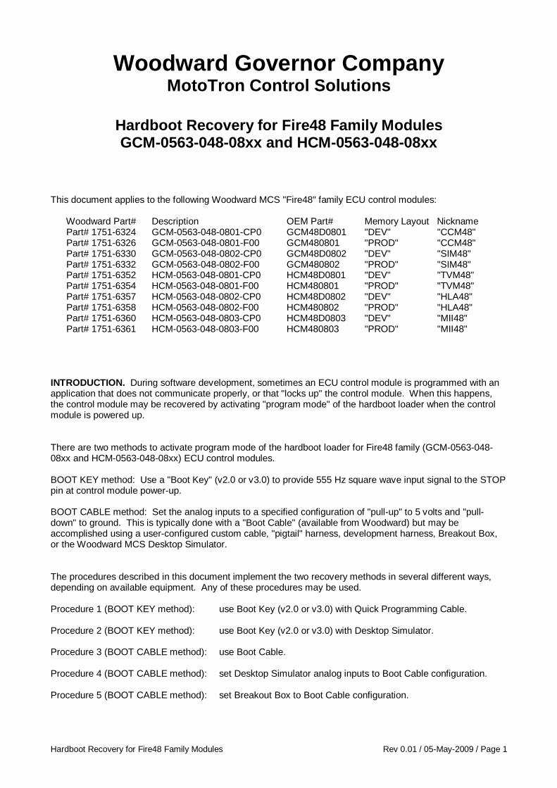
Hardboot Recovery for Fire48 Family Modules Rev 0.01 / 05-May-2009 / Page 1 Woodward Governor Company MotoTron Control Solutions Hardboot Recovery for Fire48 Family Modules GCM-0563-048-08xx and HCM-0563-048-08xx This document applies to the following Woodward MCS "Fire48" family ECU control modules: Woodward Part# Description OEM Part# Memory Layout Nickname Part# 1751-6324 GCM-0563-048-0801-CP0 GCM48D0801 "DEV" "CCM48" Part# 1751-6326 GCM-0563-048-0801-F00 GCM480801 "PROD" "CCM48" Part# 1751-6330 GCM-0563-048-0802-CP0 GCM48D0802 "DEV" "SIM48" Part# 1751-6332 GCM-0563-048-0802-F00 GCM480802 "PROD" "SIM48" Part# 1751-6352 HCM-0563-048-0801-CP0 HCM48D0801 "DEV" "TVM48" Part# 1751-6354 HCM-0563-048-0801-F00 HCM480801 "PROD" "TVM48" Part# 1751-6357 HCM-0563-048-0802-CP0 HCM48D0802 "DEV" "HLA48" Part# 1751-6358 HCM-0563-048-0802-F00 HCM480802 "PROD" "HLA48" Part# 1751-6360 HCM-0563-048-0803-CP0 HCM48D0803 "DEV" "MII48" Part# 1751-6361 HCM-0563-048-0803-F00 HCM480803 "PROD" "MII48" INTRODUCTION. During software development, sometimes an ECU control module is programmed with an application that does not communicate properly, or that "locks up" the control module. When this happens, the control module may be recovered by activating "program mode" of the hardboot loader when the control module is powered up. There are two methods to activate program mode of the hardboot loader for Fire48 family (GCM-0563-048- 08xx and HCM-0563-048-08xx) ECU control modules. BOOT KEY method: Use a "Boot Key" (v2.0 or v3.0) to provide 555 Hz square wave input signal to the STOP pin at control module power-up. BOOT CABLE method: Set the analog inputs to a specified configuration of "pull-up" to 5 volts and "pull- down" to ground. This is typically done with a "Boot Cable" (available from Woodward) but may be accomplished using a user-configured custom cable, "pigtail" harness, development harness, Breakout Box, or the Woodward MCS Desktop Simulator. The procedures described in this document implement the two recovery methods in several different ways, depending on available equipment. Any of these procedures may be used. Procedure 1 (BOOT KEY method): use Boot Key (v2.0 or v3.0) with Quick Programming Cable. Procedure 2 (BOOT KEY method): use Boot Key (v2.0 or v3.0) with Desktop Simulator. Procedure 3 (BOOT CABLE method): use Boot Cable. Procedure 4 (BOOT CABLE method): set Desktop Simulator analog inputs to Boot Cable configuration. Procedure 5 (BOOT CABLE method): set Breakout Box to Boot Cable configuration.
Transcript of Woodward Governor Company - Wander...
Hardboot Recovery for Fire48 Family Modules Rev 0.01 / 05-May-2009 / Page 1
Woodward Governor Company MotoTron Control Solutions
Hardboot Recovery for Fire48 Family Modules GCM-0563-048-08xx and HCM-0563-048-08xx
This document applies to the following Woodward MCS "Fire48" family ECU control modules: Woodward Part# Description OEM Part# Memory Layout Nickname Part# 1751-6324 GCM-0563-048-0801-CP0 GCM48D0801 "DEV" "CCM48" Part# 1751-6326 GCM-0563-048-0801-F00 GCM480801 "PROD" "CCM48" Part# 1751-6330 GCM-0563-048-0802-CP0 GCM48D0802 "DEV" "SIM48" Part# 1751-6332 GCM-0563-048-0802-F00 GCM480802 "PROD" "SIM48" Part# 1751-6352 HCM-0563-048-0801-CP0 HCM48D0801 "DEV" "TVM48" Part# 1751-6354 HCM-0563-048-0801-F00 HCM480801 "PROD" "TVM48" Part# 1751-6357 HCM-0563-048-0802-CP0 HCM48D0802 "DEV" "HLA48" Part# 1751-6358 HCM-0563-048-0802-F00 HCM480802 "PROD" "HLA48" Part# 1751-6360 HCM-0563-048-0803-CP0 HCM48D0803 "DEV" "MII48" Part# 1751-6361 HCM-0563-048-0803-F00 HCM480803 "PROD" "MII48" INTRODUCTION. During software development, sometimes an ECU control module is programmed with an application that does not communicate properly, or that "locks up" the control module. When this happens, the control module may be recovered by activating "program mode" of the hardboot loader when the control module is powered up. There are two methods to activate program mode of the hardboot loader for Fire48 family (GCM-0563-048-08xx and HCM-0563-048-08xx) ECU control modules. BOOT KEY method: Use a "Boot Key" (v2.0 or v3.0) to provide 555 Hz square wave input signal to the STOP pin at control module power-up. BOOT CABLE method: Set the analog inputs to a specified configuration of "pull-up" to 5 volts and "pull-down" to ground. This is typically done with a "Boot Cable" (available from Woodward) but may be accomplished using a user-configured custom cable, "pigtail" harness, development harness, Breakout Box, or the Woodward MCS Desktop Simulator. The procedures described in this document implement the two recovery methods in several different ways, depending on available equipment. Any of these procedures may be used. Procedure 1 (BOOT KEY method): use Boot Key (v2.0 or v3.0) with Quick Programming Cable. Procedure 2 (BOOT KEY method): use Boot Key (v2.0 or v3.0) with Desktop Simulator. Procedure 3 (BOOT CABLE method): use Boot Cable. Procedure 4 (BOOT CABLE method): set Desktop Simulator analog inputs to Boot Cable configuration. Procedure 5 (BOOT CABLE method): set Breakout Box to Boot Cable configuration.
Hardboot Recovery for Fire48 Family Modules Rev 0.01 / 05-May-2009 / Page 2
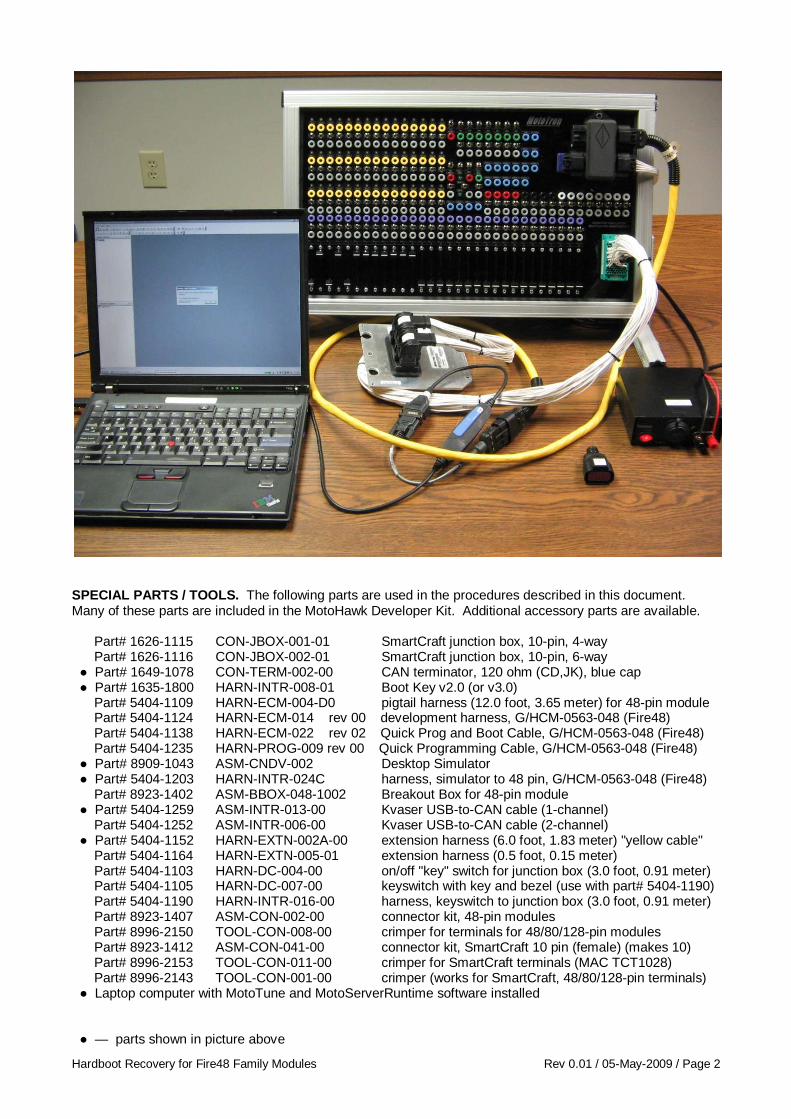
SPECIAL PARTS / TOOLS. The following parts are used in the procedures described in this document. Many of these parts are included in the MotoHawk Developer Kit. Additional accessory parts are available. Part# 1626-1115 CON-JBOX-001-01 SmartCraft junction box, 10-pin, 4-way Part# 1626-1116 CON-JBOX-002-01 SmartCraft junction box, 10-pin, 6-way ● Part# 1649-1078 CON-TERM-002-00 CAN terminator, 120 ohm (CD,JK), blue cap ● Part# 1635-1800 HARN-INTR-008-01 Boot Key v2.0 (or v3.0) Part# 5404-1109 HARN-ECM-004-D0 pigtail harness (12.0 foot, 3.65 meter) for 48-pin module Part# 5404-1124 HARN-ECM-014 rev 00 development harness, G/HCM-0563-048 (Fire48) Part# 5404-1138 HARN-ECM-022 rev 02 Quick Prog and Boot Cable, G/HCM-0563-048 (Fire48) Part# 5404-1235 HARN-PROG-009 rev 00 Quick Programming Cable, G/HCM-0563-048 (Fire48) ● Part# 8909-1043 ASM-CNDV-002 Desktop Simulator ● Part# 5404-1203 HARN-INTR-024C harness, simulator to 48 pin, G/HCM-0563-048 (Fire48) Part# 8923-1402 ASM-BBOX-048-1002 Breakout Box for 48-pin module ● Part# 5404-1259 ASM-INTR-013-00 Kvaser USB-to-CAN cable (1-channel) Part# 5404-1252 ASM-INTR-006-00 Kvaser USB-to-CAN cable (2-channel) ● Part# 5404-1152 HARN-EXTN-002A-00 extension harness (6.0 foot, 1.83 meter) "yellow cable" Part# 5404-1164 HARN-EXTN-005-01 extension harness (0.5 foot, 0.15 meter) Part# 5404-1103 HARN-DC-004-00 on/off "key" switch for junction box (3.0 foot, 0.91 meter) Part# 5404-1105 HARN-DC-007-00 keyswitch with key and bezel (use with part# 5404-1190) Part# 5404-1190 HARN-INTR-016-00 harness, keyswitch to junction box (3.0 foot, 0.91 meter) Part# 8923-1407 ASM-CON-002-00 connector kit, 48-pin modules Part# 8996-2150 TOOL-CON-008-00 crimper for terminals for 48/80/128-pin modules Part# 8923-1412 ASM-CON-041-00 connector kit, SmartCraft 10 pin (female) (makes 10) Part# 8996-2153 TOOL-CON-011-00 crimper for SmartCraft terminals (MAC TCT1028) Part# 8996-2143 TOOL-CON-001-00 crimper (works for SmartCraft, 48/80/128-pin terminals) ● Laptop computer with MotoTune and MotoServerRuntime software installed ● — parts shown in picture above

Hardboot Recovery for Fire48 Family Modules Rev 0.01 / 05-May-2009 / Page 3
Procedure 1 (BOOT KEY method): use Boot Key (v2.0 or v3.0) with Quick Programming Cable. The Quick Programming Cable is recommended for hardboot recovery using the Boot Key. The Quick Programming Cable has only the minimum number of wires required to program the module: BATT, GROUND, KEYSW (ECUP, WAKE), STOP, CAN1H, CAN1L. Other harnesses may have missing or unexpected connections that interfere with hardboot recovery. SmartCraft 10-pin G/HCM-0563-048-08xx pin A (BATT) pin B-22 (BATT) pin B (GROUND) pin B-17 (DRVG) pin E (STOP) pin B-23 (STOP) pin F (KEYSW/ECUP/WAKE) pin B-08 (KEYSW) pin J (CAN1_H) pin B-20 (CAN1_H) pin K (CAN1_L) pin B-21 (CAN1_L) Items required: ● ECU control module to be programmed – G/HCM-0563-048-08xx (Fire48) ● Boot Key (v2.0 or v3.0) ● Quick Programming Cable (Fire48) (Part# 5404-1235, HARN-PROG-009) ● ON–OFF "key" switch / power cable to connect power supply and SmartCraft junction box ● SmartCraft junction box, 10-pin, 6-way ● CAN terminator (blue cap) ● 12 Vdc (or 24 Vdc) power supply, 3 amps minimum ● Kvaser USB-to-CAN cable (1-channel or 2-channel), extension harness to SmartCraft junction box ● Laptop computer with MotoTune and MotoServerRuntime software installed
Hardboot Recovery for Fire48 Family Modules Rev 0.01 / 05-May-2009 / Page 4
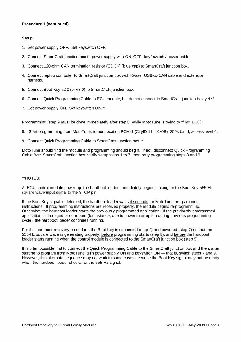
Procedure 1 (continued). Setup: 1. Set power supply OFF. Set keyswitch OFF. 2. Connect SmartCraft junction box to power supply with ON–OFF "key" switch / power cable. 3. Connect 120-ohm CAN termination resistor (CD,JK) (blue cap) to SmartCraft junction box. 4. Connect laptop computer to SmartCraft junction box with Kvaser USB-to-CAN cable and extension harness. 5. Connect Boot Key v2.0 (or v3.0) to SmartCraft junction box. 6. Connect Quick Programming Cable to ECU module, but do not connect to SmartCraft junction box yet.** 7. Set power supply ON. Set keyswitch ON.** Programming (step 9 must be done immediately after step 8, while MotoTune is trying to "find" ECU): 8. Start programming from MotoTune, to port location PCM-1 (CityID 11 = 0x0B), 250k baud, access level 4. 9. Connect Quick Programming Cable to SmartCraft junction box.** MotoTune should find the module and programming should begin. If not, disconnect Quick Programming Cable from SmartCraft junction box, verify setup steps 1 to 7, then retry programming steps 8 and 9. **NOTES: At ECU control module power-up, the hardboot loader immediately begins looking for the Boot Key 555-Hz square wave input signal to the STOP pin. If the Boot Key signal is detected, the hardboot loader waits 4 seconds for MotoTune programming instructions. If programming instructions are received properly, the module begins re-programming. Otherwise, the hardboot loader starts the previously programmed application. If the previously programmed application is damaged or corrupted (for instance, due to power interruption during previous programming cycle), the hardboot loader continues running. For this hardboot recovery procedure, the Boot Key is connected (step 4) and powered (step 7) so that the 555-Hz square wave is generating properly, before programming starts (step 8), and before the hardboot loader starts running when the control module is connected to the SmartCraft junction box (step 9). It is often possible first to connect the Quick Programming Cable to the SmartCraft junction box and then, after starting to program from MotoTune, turn power supply ON and keyswitch ON — that is, switch steps 7 and 9. However, this alternate sequence may not work in some cases because the Boot Key signal may not be ready when the hardboot loader checks for the 555-Hz signal.

Hardboot Recovery for Fire48 Family Modules Rev 0.01 / 05-May-2009 / Page 5
Procedure 2 (BOOT KEY method): use Boot Key (v2.0 or v3.0) with Desktop Simulator. To use the Desktop Simulator for hardboot recovery using BOOT KEY method, set up as described below. Items required: ● ECU control module to be programmed – G/HCM-0563-048-08xx (Fire48) ● Boot Key (v2.0 or v3.0) ● Desktop Simulator ● Desktop Simulator to ECU control module harness ● CAN terminator (blue cap) ● 12 Vdc (or 24 Vdc) power supply, 3 amps minimum ● Kvaser USB-to-CAN cable (1-channel or 2-channel), extension harness to SmartCraft junction box ● Laptop computer with MotoTune and MotoServerRuntime software installed Setup: 1. Set power supply OFF. 2. Connect Desktop Simulator power wire (red) and ground wire (black) to power supply. 3. Connect 120-ohm CAN termination resistor (CD,JK) (blue cap) to SmartCraft junction box (10-pin, 4-way) on Desktop Simulator. 4. Connect laptop computer to SmartCraft junction box with Kvaser USB-to-CAN cable and extension harness. 5. Connect Boot Key v2.0 (or v3.0) to SmartCraft junction box (10-pin, 4-way) on Desktop Simulator.
Hardboot Recovery for Fire48 Family Modules Rev 0.01 / 05-May-2009 / Page 6
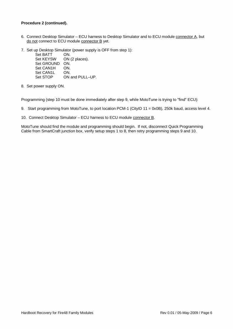
Procedure 2 (continued). 6. Connect Desktop Simulator – ECU harness to Desktop Simulator and to ECU module connector A, but do not connect to ECU module connector B yet. 7. Set up Desktop Simulator (power supply is OFF from step 1): Set BATT ON. Set KEYSW ON (2 places). Set GROUND ON. Set CAN1H ON. Set CAN1L ON. Set STOP ON and PULL–UP. 8. Set power supply ON. Programming (step 10 must be done immediately after step 9, while MotoTune is trying to "find" ECU): 9. Start programming from MotoTune, to port location PCM-1 (CityID 11 = 0x0B), 250k baud, access level 4. 10. Connect Desktop Simulator – ECU harness to ECU module connector B. MotoTune should find the module and programming should begin. If not, disconnect Quick Programming Cable from SmartCraft junction box, verify setup steps 1 to 8, then retry programming steps 9 and 10.
Hardboot Recovery for Fire48 Family Modules Rev 0.01 / 05-May-2009 / Page 7
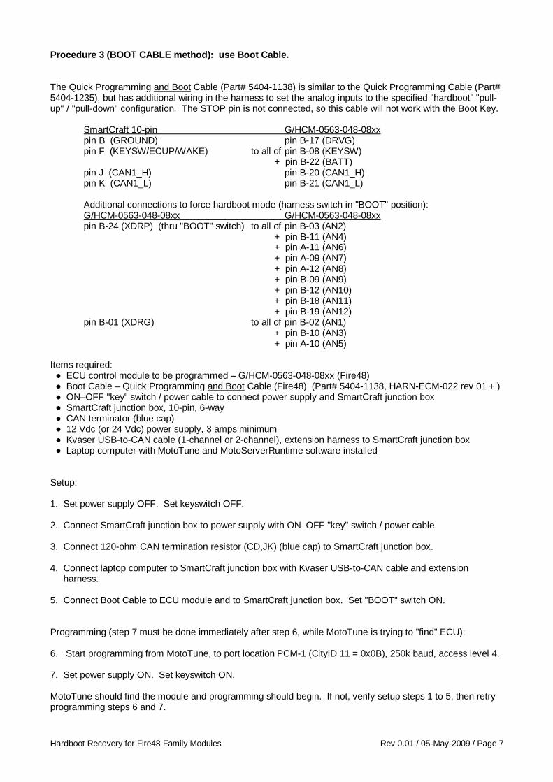
Procedure 3 (BOOT CABLE method): use Boot Cable. The Quick Programming and Boot Cable (Part# 5404-1138) is similar to the Quick Programming Cable (Part# 5404-1235), but has additional wiring in the harness to set the analog inputs to the specified "hardboot" "pull-up" / "pull-down" configuration. The STOP pin is not connected, so this cable will not work with the Boot Key. SmartCraft 10-pin G/HCM-0563-048-08xx pin B (GROUND) pin B-17 (DRVG) pin F (KEYSW/ECUP/WAKE) to all of pin B-08 (KEYSW) + pin B-22 (BATT) pin J (CAN1_H) pin B-20 (CAN1_H) pin K (CAN1_L) pin B-21 (CAN1_L) Additional connections to force hardboot mode (harness switch in "BOOT" position): G/HCM-0563-048-08xx G/HCM-0563-048-08xx pin B-24 (XDRP) (thru "BOOT" switch) to all of pin B-03 (AN2) + pin B-11 (AN4) + pin A-11 (AN6) + pin A-09 (AN7) + pin A-12 (AN8) + pin B-09 (AN9) + pin B-12 (AN10) + pin B-18 (AN11) + pin B-19 (AN12) pin B-01 (XDRG) to all of pin B-02 (AN1) + pin B-10 (AN3) + pin A-10 (AN5) Items required: ● ECU control module to be programmed – G/HCM-0563-048-08xx (Fire48) ● Boot Cable – Quick Programming and Boot Cable (Fire48) (Part# 5404-1138, HARN-ECM-022 rev 01 + ) ● ON–OFF "key" switch / power cable to connect power supply and SmartCraft junction box ● SmartCraft junction box, 10-pin, 6-way ● CAN terminator (blue cap) ● 12 Vdc (or 24 Vdc) power supply, 3 amps minimum ● Kvaser USB-to-CAN cable (1-channel or 2-channel), extension harness to SmartCraft junction box ● Laptop computer with MotoTune and MotoServerRuntime software installed Setup: 1. Set power supply OFF. Set keyswitch OFF. 2. Connect SmartCraft junction box to power supply with ON–OFF "key" switch / power cable. 3. Connect 120-ohm CAN termination resistor (CD,JK) (blue cap) to SmartCraft junction box. 4. Connect laptop computer to SmartCraft junction box with Kvaser USB-to-CAN cable and extension harness. 5. Connect Boot Cable to ECU module and to SmartCraft junction box. Set "BOOT" switch ON. Programming (step 7 must be done immediately after step 6, while MotoTune is trying to "find" ECU): 6. Start programming from MotoTune, to port location PCM-1 (CityID 11 = 0x0B), 250k baud, access level 4. 7. Set power supply ON. Set keyswitch ON. MotoTune should find the module and programming should begin. If not, verify setup steps 1 to 5, then retry programming steps 6 and 7.
Hardboot Recovery for Fire48 Family Modules Rev 0.01 / 05-May-2009 / Page 8
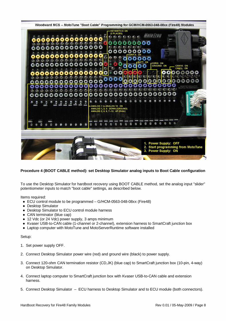
Procedure 4 (BOOT CABLE method): set Desktop Simulator analog inputs to Boot Cable configuration To use the Desktop Simulator for hardboot recovery using BOOT CABLE method, set the analog input "slider" potentiometer inputs to match "boot cable" settings, as described below. Items required: ● ECU control module to be programmed – G/HCM-0563-048-08xx (Fire48) ● Desktop Simulator ● Desktop Simulator to ECU control module harness ● CAN terminator (blue cap) ● 12 Vdc (or 24 Vdc) power supply, 3 amps minimum ● Kvaser USB-to-CAN cable (1-channel or 2-channel), extension harness to SmartCraft junction box ● Laptop computer with MotoTune and MotoServerRuntime software installed Setup: 1. Set power supply OFF. 2. Connect Desktop Simulator power wire (red) and ground wire (black) to power supply. 3. Connect 120-ohm CAN termination resistor (CD,JK) (blue cap) to SmartCraft junction box (10-pin, 4-way) on Desktop Simulator. 4. Connect laptop computer to SmartCraft junction box with Kvaser USB-to-CAN cable and extension harness. 5. Connect Desktop Simulator – ECU harness to Desktop Simulator and to ECU module (both connectors).

Hardboot Recovery for Fire48 Family Modules Rev 0.01 / 05-May-2009 / Page 9
Procedure 4 (continued). 6. Set up Desktop Simulator (power supply is OFF from step 1): Set BATT ON.** Set KEYSW ON (2 places).** Set GROUND ON. Set CAN1H ON. Set CAN1L ON. Set XDRP_A ON. Set XDRG ON. Set analog inputs 1 through 12 ON. Set analog input sliders DOWN for: 1, 3, 5. Set analog input sliders UP for: 2, 4, 6, 7, 8, 9, 10, 11, 12. Programming (step 8 must be done immediately after step 7, while MotoTune is trying to "find" ECU): 7. Start programming from MotoTune, to port location PCM-1 (CityID 11 = 0x0B), 250k baud, access level 4. 8. Set power supply ON.** MotoTune should find the module and programming should begin. If not, verify setup steps 1 to 6, then retry programming steps 7 and 8. After Programming: 9. Change settings for analog input sliders. Otherwise, the ECU module will re-enter hardboot mode at next power-up. Set analog input sliders DOWN for: 2, 4, 6, 7, 8, 9, 10, 11, 12. **NOTES: The Fire48 family of ECU modules requires both BATT and KEYSW to be set ON for the module to power up. Because the Fire48 family of ECU modules uses "controlled shutdown," both BATT and KEYSW must be disconnected for the module to be completely powered down. When BATT is connected and KEYSW is OFF, the application code in the module may still be running, depending on its shutdown algorithm. By using the power supply to set power ON / OFF, power is provided to / removed from both BATT and KEYSW at the same time. After the Desktop Simulator is set up properly, the BATT and KEYSW switches may be used to set power ON or OFF for hardboot recovery (BOOT CABLE method).
Hardboot Recovery for Fire48 Family Modules Rev 0.01 / 05-May-2009 / Page 10
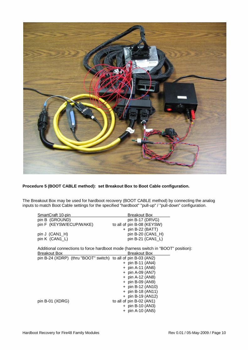
Procedure 5 (BOOT CABLE method): set Breakout Box to Boot Cable configuration. The Breakout Box may be used for hardboot recovery (BOOT CABLE method) by connecting the analog inputs to match Boot Cable settings for the specified "hardboot" "pull-up" / "pull-down" configuration. SmartCraft 10-pin Breakout Box pin B (GROUND) pin B-17 (DRVG) pin F (KEYSW/ECUP/WAKE) to all of pin B-08 (KEYSW) + pin B-22 (BATT) pin J (CAN1_H) pin B-20 (CAN1_H) pin K (CAN1_L) pin B-21 (CAN1_L) Additional connections to force hardboot mode (harness switch in "BOOT" position): Breakout Box Breakout Box pin B-24 (XDRP) (thru "BOOT" switch) to all of pin B-03 (AN2) + pin B-11 (AN4) + pin A-11 (AN6) + pin A-09 (AN7) + pin A-12 (AN8) + pin B-09 (AN9) + pin B-12 (AN10) + pin B-18 (AN11) + pin B-19 (AN12) pin B-01 (XDRG) to all of pin B-02 (AN1) + pin B-10 (AN3) + pin A-10 (AN5)
Hardboot Recovery for Fire48 Family Modules Rev 0.01 / 05-May-2009 / Page 11
Procedure 5 (continued). Items required: ● ECU control module to be programmed – G/HCM-0563-048-08xx (Fire48) ● Breakout Box with jumper wires (need extra jumper wires and SmartCraft 10-pin junction box connector) ● ON–OFF "key" switch / power cable to connect power supply and SmartCraft junction box ● SmartCraft junction box, 10-pin, 6-way ● CAN terminator (blue cap) ● 12 Vdc (or 24 Vdc) power supply, 3 amps minimum ● Kvaser USB-to-CAN cable (1-channel or 2-channel), extension harness to SmartCraft junction box ● Laptop computer with MotoTune and MotoServerRuntime software installed Setup: 1. Set power supply OFF. Set keyswitch OFF. 2. Connect SmartCraft junction box to power supply with ON–OFF "key" switch / power cable. 3. Connect 120-ohm CAN termination resistor (CD,JK) (blue cap) to SmartCraft junction box. 4. Connect laptop computer to SmartCraft junction box with Kvaser USB-to-CAN cable and extension harness. 5. Connect Breakout Box to ECU module. 6. Connect Breakout Box to SmartCraft junction box according to table above, using jumper wires and a SmartCraft 10-pin female connector (Part# 8923-1412, ASM-CON-041-00). 7. Connect Breakout Box pins for analog input pull-up to XDRP / pull-down to XDRG according to table above, using jumper wires. Programming (step 9 must be done immediately after step 8, while MotoTune is trying to "find" ECU): 8. Start programming from MotoTune, to port location PCM-1 (CityID 11 = 0x0B), 250k baud, access level 4. 9. Set power supply ON. Set keyswitch ON. MotoTune should find the module and programming should begin. If not, verify setup steps 1 to 7, then retry programming steps 8 and 9. After Programming: 10. Disconnect jumpers XDRP (B-24) and XDRG (B-01) on Breakout Box pins for analog input pull-up / pull-down. Otherwise, the ECU module will re-enter hardboot mode at next power-up. END OF DOCUMENT.