WOODLAKE DAM TEMPORARY BREACH DESIGN – CONCEPT …
20
WOODLAKE DAM TEMPORARY BREACH DESIGN – CONCEPT SUBMITTAL Woodlake Dam Rehabilitation Woodlake CC Corp. Vass, NC Schnabel Reference No: 17C21008.00 April 10, 2017
Transcript of WOODLAKE DAM TEMPORARY BREACH DESIGN – CONCEPT …

WOODLAKE DAM TEMPORARY BREACH DESIGN – CONCEPT SUBMITTAL
Woodlake Dam Rehabilitation
Woodlake CC Corp.
Vass, NC
Schnabel Reference No: 17C21008.00
April 10, 2017

WOODLAKE DAM TEMPORARY BREACH DESIGN – CONCEPT SUBMITTAL
Woodlake Dam Rehabilitation
Woodlake CC Corp.
Vass, NC
Schnabel Reference No: 17C21008.00
April 10, 2017
_________________________________________
Laura Shearin, PE, ENV SP
NC Professional Engineering No. 037496
Schnabel Engineering South, P.C.
License Number C-2599
lshearin
4-10-17

April 10, 2017 Mr. Brian Shane Cook, PE, LSIT State Dam Safety Engineer NC DEQ - Land Quality Section 512 N. Salisbury Street, Room 519 1612 Mail Service Raleigh, NC 27604
Subject: Project 17C21008.00, Woodlake Dam Temporary Breach Design – Concept Submittal, Vass, NC
Dear Mr. Cook:
SCHNABEL ENGINEERING SOUTH, P.C. (Schnabel) is pleased to submit our concept for the breach design at Woodlake Dam on the behalf of Woodlake CC Corp. (WCCC). This report includes tables, and appendices with relevant data collected for this design.
We appreciate the opportunity to be of service for this project. Please call us if you have any questions regarding this report. Sincerely, SCHNABEL ENGINEERING SOUTH, P.C. Robert Indri, PE Associate
RTI:LS:MEL
Distribution: Client (1 Copy), Attn: Chris Meng and David Harris
NCDEQ: Dam Safety (2 Copies) Attn: Shane Cook, PE; State Dam Safety Engineer

Woodlake CC Corp.
Woodlake Dam Rehabilitation
April 10, 2017 Page i Schnabel Engineering South, P.C. Project 17C21008.00 ©2017 All Rights Reserved
WOODLAKE DAM TEMPORARY BREACH DESIGN – CONCEPT SUBMITTAL
WOODLAKE DAM REHABILITATION
WOODLAKE CC CORP.
VASS, NC
CONTENTS
1.0 DESCRIPTION OF SITE AND PROPOSED CONSTRUCTION ................................................... 1
1.1 Site Description
1.2 Project History
1.3 Status of Temporary Full Breach Design Submittal
1.4 Proposed Temporary Full Breach
2.0 HYDRAULICS AND HYDROLOGY ............................................................................................ 2
2.1 Standard Design Flood
2.2 Watershed Hydrology
2.3 Reservoir and Temporary Full Breach Routing
2.4 Temporary Full Breach Lining
3.0 REFERENCES ........................................................................................................................... 3
TABLES
Table 1: Headwater/Tailwater
APPENDICES
Appendix A: Drawings
Appendix B: Hydraulic and Hydrology Calculations

Woodlake CC Corp.
Woodlake Dam Rehabilitation
April 10, 2017 Page 1 Schnabel Engineering South, P.C. Project 17C21008.00 ©2017 All Rights Reserved
1.0 DESCRIPTION OF SITE AND PROPOSED CONSTRUCTION
1.1 Site Description
Woodlake Dam is located in Moore County, North Carolina, approximately 2,450 feet northwest of the
intersection of Lobelia Road (SR 690) and McGill Road (SR 2017). The dam is owned by Woodlake CC
Corp (WCCC). The primary purpose of the impoundment is recreation. Water from the impoundment is
also used for irrigation at the adjacent Woodlake golf course. The dam impounds Lake Surf and has a
maximum impoundment capacity of approximately 10,000 acre-feet at the top of the dam. Woodlake Dam
is considered a large sized, high hazard dam by NCDEQ Dam Safety. A Site Vicinity Map is included in
Appendix A.
Woodlake Dam consists of: an approximately 23 foot-high earth embankment; a reinforced concrete
chute principal spillway with approximately 3.5-foot-high metal slide gates across the control section of
the chute; and, two low-level outlets as independent structures.
1.2 Project History
In early October (starting on October 9, 2016), high water flows through the principal spillway from
Hurricane Matthew caused portions of the concrete spillway to undermine, collapse, and displace.
Emergency measures were taken, including opening of the two low-level outlets gates, and installation of
large pumps to decrease the water levels in the reservoir. The principal gates were closed in an attempt
to reduce flows through the principal spillway and reduce the potential for continued displacement of the
spillway slabs and erosion of the spillway subgrade. The Emergency Action Plan (EAP) for the project
was implemented and downstream residences in the breach inundation zone were notified and
evacuated.
During an on-site inspection on October 12, 2016, NCDEQ Dam Safety noted the following deficiencies at
the dam:
� The middle section of the concrete spillway on the downstream side had collapsed;
� Erosion under the collapsed spillway section had occurred;
� The seepage drainage system had been damaged;
� The downstream spillway walls had been overtopped and soil erosion had occurred from behind
the walls; and,
� Most of the gates were not completely functional and were damaged.
Under a March 15, 2017 court order, the owner has been ordered to:
� Maintain the water level in the impoundment at an elevation of EL 211 or below; and,
� Finish design and construction of a temporary full breach of the dam within 105 days of issuance
of the court order.
1.3 Status of Temporary Full Breach Design Submittal
This report and attached drawings represents our concept submittal for temporary full breach of
Woodlake Dam. The final breach design will be developed for submission to Dam Safety for review and

Woodlake CC Corp.
Woodlake Dam Rehabilitation
April 10, 2017 Page 2 Schnabel Engineering South, P.C. Project 17C21008.00 ©2017 All Rights Reserved
approval pending completion of a topographic survey of the site. The concept is based on 2005 LiDAR
obtained from NC Floodplain Mapping. We do not consider the LIDAR topographic data and historical
drawings used to develop the concept submittal sufficient for final design of the breach. Our surveying
sub consultant, Allied Associates, PA (Allied), mobilized to the site on April 5, 2017 to begin the site
survey.
To meet project deadlines, the client has elected to pursue a design-build contract for completion of the
breach. Crowder Construction (Crowder) has been selected as the general contractor and WCCC is
currently in the preliminary stages of negotiating a contract with Crowder. Crowder will work with
Schnabel during the design phase by providing constructability reviews and cost estimating. Modifications
to the concept submittal based on Crowder’s input will be included in the final design submittal.
The intent and concepts presented are not expected to significantly change as we prepare the final
design. If significant modifications are required based on the results of the survey and constructability
review, we will contact Dam Safety to review the modifications.
1.4 Proposed Temporary Full Breach
The proposed temporary full breach will include removal of the existing principal spillway in its entirety. A
two-stage armored channel will be constructed centered on the existing principal spillway. The details of
the channel are outlined in the next section of this report and shown on the figures included in Appendix
A. Construction access will be from McGill Road to the left abutment of the dam. A spoils disposal area
has been identified by the Owner and is shown in the figures included in Appendix A.
2.0 HYDRAULICS AND HYDROLOGY
2.1 Standard Design Flood
Woodlake Dam is considered a large sized, high hazard dam. The standard design flood (SDF) for this
structure is the ¾ Probable Maximum Precipitation (PMP). Our understanding is NC Dam Safety requires
the temporary full breach design to be sized to pass the ¾ PMP, including full armoring within the breach
section of the embankment up to the water surface elevation of the ¾ PMP.
2.2 Watershed Hydrology
The 95 square mile watershed was modeled as a single basin. An SCS runoff curve number of 68 was
calculated using the National Land Cover Dataset cover and USDA Soils data for Harnett, Lee, and
Moore Counties. A Snyder’s Lag Time of 9.9 hours was calculated using an average watershed slope of
6.22% and a stream length of 16.56 miles. A peaking coefficient of 0.4 was selected based on other
regional basin analyses. The watershed and reservoir were modeled using HEC-HMS 4.2.
The rainfall for the PMP was obtained from HMR 51 and distributed in the HEC-HMS model. The rainfall
for the 100-year and 500-year storms was obtained from NOAA Atlas 14. All storms were modeled with a
24-hour duration.
Woodlake CC Corp. Woodlake Dam Rehabilitation
April 10, 2017 Page 3 Schnabel Engineering South, P.C. Project 17C21008.00 ©2017 All Rights Reserved
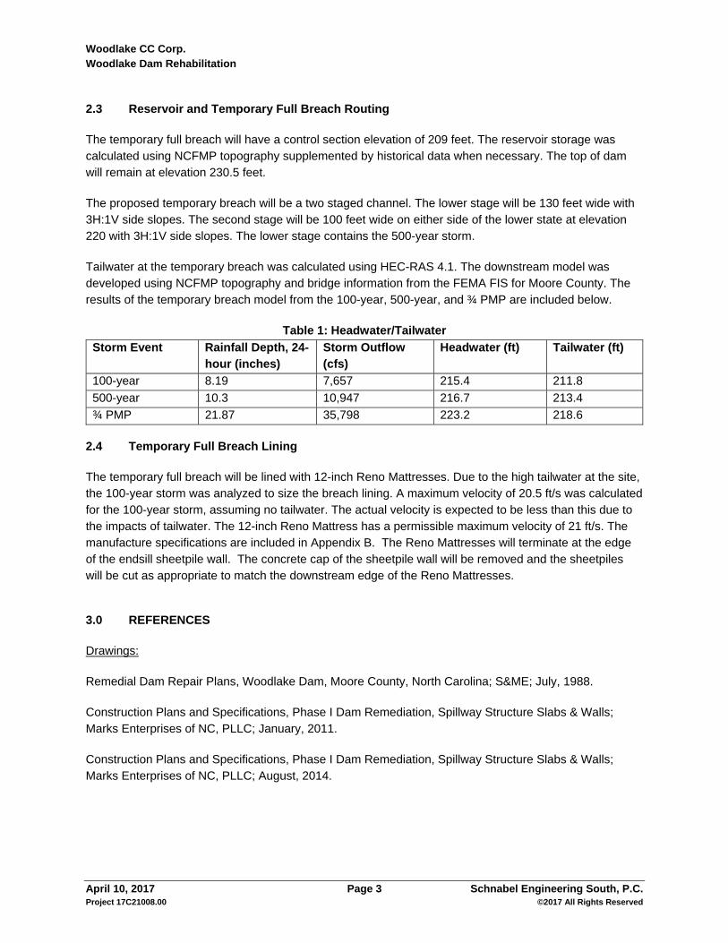
2.3 Reservoir and Temporary Full Breach Routing
The temporary full breach will have a control section elevation of 209 feet. The reservoir storage was calculated using NCFMP topography supplemented by historical data when necessary. The top of dam will remain at elevation 230.5 feet.
The proposed temporary breach will be a two staged channel. The lower stage will be 130 feet wide with 3H:1V side slopes. The second stage will be 100 feet wide on either side of the lower state at elevation 220 with 3H:1V side slopes. The lower stage contains the 500-year storm.
Tailwater at the temporary breach was calculated using HEC-RAS 4.1. The downstream model was developed using NCFMP topography and bridge information from the FEMA FIS for Moore County. The results of the temporary breach model from the 100-year, 500-year, and ¾ PMP are included below.
Table 1: Headwater/Tailwater
Storm Event Rainfall Depth, 24-hour (inches)
Storm Outflow (cfs)
Headwater (ft) Tailwater (ft)
100-year 8.19 7,657 215.4 211.8
500-year 10.3 10,947 216.7 213.4
¾ PMP 21.87 35,798 223.2 218.6
2.4 Temporary Full Breach Lining
The temporary full breach will be lined with 12-inch Reno Mattresses. Due to the high tailwater at the site, the 100-year storm was analyzed to size the breach lining. A maximum velocity of 20.5 ft/s was calculated for the 100-year storm, assuming no tailwater. The actual velocity is expected to be less than this due to the impacts of tailwater. The 12-inch Reno Mattress has a permissible maximum velocity of 21 ft/s. The manufacture specifications are included in Appendix B. The Reno Mattresses will terminate at the edge of the endsill sheetpile wall. The concrete cap of the sheetpile wall will be removed and the sheetpiles will be cut as appropriate to match the downstream edge of the Reno Mattresses.
3.0 REFERENCES
Drawings:
Remedial Dam Repair Plans, Woodlake Dam, Moore County, North Carolina; S&ME; July, 1988.
Construction Plans and Specifications, Phase I Dam Remediation, Spillway Structure Slabs & Walls; Marks Enterprises of NC, PLLC; January, 2011.
Construction Plans and Specifications, Phase I Dam Remediation, Spillway Structure Slabs & Walls; Marks Enterprises of NC, PLLC; August, 2014.

Woodlake CC Corp.
Woodlake Dam Rehabilitation
April 10, 2017 Page 4 Schnabel Engineering South, P.C. Project 17C21008.00 ©2017 All Rights Reserved
Reports:
Dam Remediation Design Submittal, Woodlake Dam Phase I Spillway Remediation; Marks Enterprises of
NC, PLLC; January 17, 2011.
Review Comments Responses Documents, Dam Remediation Design Submittal, Woodlake Dam Phase I
Spillway Remediation; Marks Enterprises of NC, PLLC; September 1, 2014.

Woodlake CC Corp.
Woodlake Dam Rehabilitation
April 10, 2017 Page 5 Schnabel Engineering South, P.C. Project 17C21008.00 ©2017 All Rights Reserved
APPENDIX A
DRAWINGS

WOODLAKE DAM TEMPORARY
FULL BREACH
WOODLAKE CC CORP
VASS, NORTH CAROLINA
© Schnabel Engineering 2017 All Rights Reserved
WOODLAKE CC CORP
PREPARED BY
SCHNABEL ENGINEERING SOUTH, PC
LOCATION MAP
VASS, NORTH CAROLINA
VICINITY MAP
PREPARED FOR
WOODLAKE DAM TEMPORARY FULL BREACH
PROJECT
SITE
M
C
G
IL
L
R
D
L
O
B
E
L
IA
R
D
PROJECT
SITE
PROJECT
SITE
MOORE
COUNTY
FIGURE 1
COVER SHEET

210
210
220
220
230
230
2
1
0
208
2
0
8
2
0
6
206
206
210
2
0
8
210
210
220
220
230
230
212
2
1
0
208
2
1
4
214
2
1
6
2
1
8
2
2
0
2
2
4
2
2
2
2
2
6
2
2
8
2
3
0
2
3
2
2
3
4
2
3
6
2
3
8
2
4
0
2
4
2
M
C
G
I
L
L
R
D
2
0
6
208
17+00
18+00
19+00
20+00
21+00
22+00
23+00
24+00
25+00
26+00
27+00
28+00
29+00
30+00
31+00
32+00
33+00
34+00
35+00
36+00
37+00
38+00
39+00
40+00
41+00
42+00
43+00
44+00
45+00
46+00
47+00
48
+0
04
9+
00
50
+0
05
1+
00
52
+0
0
NOTES
1. EXISTING GROUND CONTOURS ARE FROM 2005 LiDAR
TOPOGRAPHY OBTAINED FROM NC FLOODPLAIN MAPPING.
LARGE AREAS OF THE LiDAR POINT DATA WERE NOT PRESENT
IN MULTIPLE DATA SETS THAT SCHNABEL INVESTIGATED.
2. BECAUSE OF THE MISSING GROUND DATA ALONG THE TOP OF
THE EXISTING EMBANKMENT, CONTOURS FOR THE EARTHEN
EMBANKMENT HAVE BEEN ADDED BASED ON HISTORICAL
DRAWINGS, AND FIELD OBSERVATIONS.
3. CONTRACTOR SHALL ACCESS THE SITE FROM SR-690 (LOBELIA
RD) TO MCGILL RD TO LEFT ABUTMENT.
4. EROSION AND SEDIMENT CONTROL MEASURES WILL BE
PROVIDED AT A LATER DATE.
5. LAKE WILL BE MAINTAINED IN A DRAINED CONDITION BEFORE,
DURING, AND AFTER CONSTRUCTION, WITH WATER SURFACE AT
ELEVATION 211 OR BELOW.
6. CONCRETE RUBBLE, METALS, AND EXCESS SOIL WILL BE
PLACED IN THE POTENTIAL DISPOSAL AREAS.
7. REMOVE ALL CONCRETE. SHEETPILES LOCATED BENEATH THE
DOWNSTREAM ENDSILL TO BE LEFT IN PLACE. THE TOP OF THE
SHEETPILES WILL BE CUT TO MATCH THE DOWNSTREAM
SECTION OF ARMORING.
N
UPSTREAM COFFERDAM TO PROVIDE 1-YEAR STORM PROTECTION
ESTIMATED LOCATIONS OF
DOWNSTREAM COFFERDAMS
TO PROVIDE 1-YEAR STORM PROTECTION
POTENTIAL
CONTRACTOR
STAGING AREA
EXISTING SPILLWAY
EXISTING RISER
FOR LOW LEVEL OUTLET
EXISTING RISER
FOR LOW LEVEL OUTLET
ASSUMED EMBANKMENT GRADING
SEE NOTE 2
POTENTIAL
DISPOSAL
AREA
WOODLAKE DAM TEMPORARY
FULL BREACH
WOODLAKE CC CORP
VASS, NORTH CAROLINA
© Schnabel Engineering 2017 All Rights Reserved
00 200' 400'
SCALE: 1"=200'
FIGURE 2
SITE ACCESS AND
CONSTRUCTION LIMITS
A
P
P
R
O
X
I
M
A
T
E
L
Y
0
.
2
5
M
I
L
E
S
T
O
L
O
B
E
L
I
A
R
O
A
D
(
S
R
6
9
0
)
LIMITS OF
CONSTRUCTION
LIMITS OF CONSTRUCTION
CONSTRUCTION
ACCESS ROAD

210
210
220
220
230
230
2
1
0
208
2
0
8
2
0
6
206
206
210
2
0
8
210
210
220
220
230
230
212
208
2
1
4
214
230
210
210
220
220
27+00
28+00
29+00
30+00
31+00
32+00
33+00
34+00
35+00
36+00
37+00
38+00
39+00
40+00
41+00
42+00
48
+0
04
9+
00
50
+0
05
1+
00
52
+0
0
NOTES
1. EXCAVATE TO MATCH GRADES AS SHOWN. PROVIDE SMOOTH
AND LEVEL PLATFORM FOR FABRIC AND RENO MATTRESS
PLACEMENT.
2. RENO MATTRESS SHALL BE PVC COATED MACCAFERRI (OR
APPROVED EQUIVALENT) 12-INCH RENO MATTRESS, STONE SIZE
3.9 TO 5.9-INCH DIAMETER WITH D50 = 4.9 INCHES. PROVIDE
MIRAFTI 180N UNDERNEATH MATTRESSES.
N
UPSTREAM COFFERDAM
TO PROVIDE 1-YEAR STORM PROTECTION
ESTIMATED LOCATIONS OF
DOWNSTREAM COFFERDAMS
TO PROVIDE 1-YEAR STORM PROTECTION
EXISTING RISER
FOR LOW LEVEL OUTLET
WOODLAKE DAM TEMPORARY
FULL BREACH
WOODLAKE CC CORP
VASS, NORTH CAROLINA
© Schnabel Engineering 2017 All Rights Reserved
00 100' 200'
SCALE: 1"=100'
3:1
3:1
3:1
3:1
FIGURE 3
TEMPORARY FULL BREACH
PLAN
LIMITS OF CONSTRUCTION
LIMITS OF RENO MATTING
EXISTING RISER
FOR LOW LEVEL OUTLET
1
FIG4
1
FIG4
2
FIG4
2
FIG4
STAGE 1
EL ~209.0
2%
STAGE 2
EL ~220.0
STAGE 2
EL ~220.0

INTERIOR WIDTH OF EXISTING SPILLWAY
273.67'
TOP OF EXISTING CONTROL SECTION SLAB
EL 221.75
TOP OF BREACH CHANNEL AT CONTROL SECTION
EL 209
3:1 SLOPE (TYP)
CENTERLINE OF SPILLWAY
STAGE 1
130.00'
33.00'
STAGE 2
100.00'
31.50'
3/4 PMP WATER SURFACE
EL 223.2
500 YEAR WATER SURFACE
EL 216.4
EL 220
459.00'
TOP OF EMBANKMENT
EL 230.5
ELE
VA
TIO
N
STATION
180
200
220
240
260
180
200
220
240
260
48+00 49+00 50+00 51+00 52+00
48+20 48+40 48+60 48+80 49+00 49+20 49+40 49+60 49+80 50+00 50+20 50+40 50+60 50+80 51+00 51+20 51+40 51+60 51+80 52+00
3/4 PMP WATER SURFACE
EL 223.2
500-YEAR STORM WATER SURFACE
EL 216.7
100-YEAR STORM WATER SURFACE
EL 215.4
3/4 PMP TAILWATER SURFACE
EL 218.6
500-YEAR STORM TAILWATER SURFACE
EL 213.4
100-YEAR STORM TAILWATER SURFACE
EL 211.8
2% SLOPE
UPSTREAM COFFERDAM
TOP EL 213.0
1.00'
RENO MATTRESS
SEE NOTES
STAGE 2
EL ~220.0
STAGE 1
EL ~209.0
TOP OF EXISTING EMBANKMENT
TOP EL 230.5
NOTES
1. EXCAVATE TO MATCH GRADES AS SHOWN. PROVIDE SMOOTH
AND LEVEL PLATFORM FOR FABRIC AND RENO MATTRESS
PLACEMENT.
2. RENO MATTRESS SHALL BE PVC COATED MACCAFERRI (OR
APPROVED EQUIVALENT) 12-INCH RENO MATTRESS, STONE SIZE
3.9 TO 5.9-INCH DIAMETER WITH D50 = 4.9 INCHES. PROVIDE
MIRAFTI 180N UNDERNEATH MATTRESSES.
WOODLAKE DAM TEMPORARY
FULL BREACH
WOODLAKE CC CORP
VASS, NORTH CAROLINA
© Schnabel Engineering 2017 All Rights Reserved
00 40' 80'
SCALE: 1"=40'
00 30' 60'
SCALE: 1"=30'
FIGURE 4
TEMPORARY FULL BREACH
PROFILE AND SECTION
TEMPORARY FULL BREACH PROFILE1
FIG3
SECTION AT CENTERLINE OF EXISTING EMBANKMENT2
FIG3

Woodlake CC Corp.
Woodlake Dam Rehabilitation
April 10, 2017 Page 6 Schnabel Engineering South, P.C. Project 17C21008.00 ©2017 All Rights Reserved
APPENDIX B
HYDRAULIC AND HYDROLOGIC CALCULATIONS

Project: Woodlake Dam Simulation Run: 0.75 PMP- PostBr
Reservoir: Woodlake Dam
Start of Run: 01Jan2017, 00:00 Basin Model: Temporary Breach
End of Run: 07Jan2017, 00:00 Meteorologic Model: Woodlake PMP-24hr
Compute Time: 08Apr2017, 08:43:20 Control Specifications: 6 days, 5 min incr
Volume Units:IN
Computed ResultsPeak Inflow: 39255.9 (CFS) Date/Time of Peak Inflow: 02Jan2017, 01:05Peak Discharge: 35798.4 (CFS) Date/Time of Peak Discharge:02Jan2017, 04:35Inflow Volume: 17.09 (IN) Peak Storage: 10816.6 (AC-FT)Discharge Volume:17.08 (IN) Peak Elevation: 223.17 (FT)

Project: Woodlake Dam Simulation Run: 500-year - PostBr
Reservoir: Woodlake Dam
Start of Run: 01Jan2017, 00:00 Basin Model: Temporary Breach
End of Run: 07Jan2017, 00:00 Meteorologic Model: 500-year-24hr
Compute Time: 08Apr2017, 08:42:19 Control Specifications: 6 days, 5 min incr
Volume Units:IN
Computed Results
Peak Inflow: 12312.0 (CFS) Date/Time of Peak Inflow: 01Jan2017, 22:55Peak Discharge: 10946.6 (CFS) Date/Time of Peak Discharge:02Jan2017, 04:15Inflow Volume: 5.61 (IN) Peak Storage: 4497.2 (AC-FT)Discharge Volume:5.60 (IN) Peak Elevation: 216.73 (FT)

Project: Woodlake Dam Simulation Run: 100-year - PostBr
Reservoir: Woodlake Dam
Start of Run: 01Jan2017, 00:00 Basin Model: Temporary Breach
End of Run: 07Jan2017, 00:00 Meteorologic Model: 100-year-24hr
Compute Time:08Apr2017, 08:41:38 Control Specifications: 6 days, 5 min incr
Volume Units:IN
Computed ResultsPeak Inflow: 8517.3 (CFS) Date/Time of Peak Inflow: 01Jan2017, 23:10Peak Discharge: 7657.1 (CFS) Date/Time of Peak Discharge:02Jan2017, 04:25Inflow Volume: 3.93 (IN) Peak Storage: 3361.3 (AC-FT)Discharge Volume:3.92 (IN) Peak Elevation: 215.35 (FT)

Trapezoidal Channel Normal Depth Calculations
Inputs
Flow Rate (cfs) 7657
Bottom Width (ft) 130
Side Slope (ft/ft) 3
Channel Slope (ft/ft) 0.042
Manning's n 0.0277
Results
Normal Depth (ft) 2.71
Area (ft2) 373.95
Wetted Perimeter (ft) 147.12
Channel Velocity (ft/s) 20.48
Calculate

Thickness Critical Velocity Limit Velocity
(in) Stone Size d50 (fps) (fps)
Reno mattress 6 2.8 ‐ 3.9 3.4 11.5 13.8
Reno mattress 6 2.8 ‐ 5.0 4.3 13.8 14.8
Reno mattress 9 2.8 ‐ 3.9 3.4 11.8 18.0
Reno mattress 9 2.8 ‐ 5.9 4.7 14.8 20.0
Reno mattress 12 2.8 ‐ 4.7 3.9 13.8 18.0
Reno mattress 12 3.9 ‐ 5.9 4.9 16.4 21.0
Gabions 18 3.9 ‐ 8.0 5.9 19.0 25.0
Filling stones (in)Type
ALLOWABLE WATER VELOCITIES
Gabions 18 3.9 8.0 5.9 19.0 25.0
Gabions 18 4.7 ‐ 9.8 7.5 21.0 26.2

ALLOWABLE SHEAR STRESSES
Roughness n Roughness n
(inch) (inch) (Manning) (Manning)
Gabions (18 inch) 4.0 ‐ 10 7.50 0.0301 7.14 0.07 ‐ 0.4 (d) 8.35
Reno Mattress (6 inch) 2.8 ‐ 5.0 3.90 0.0277 4.26 0.07 ‐ 0.4 (d) 8.35
Reno Mattress (9 inch) 2.8 ‐ 5.9 4.70 0.0277 4.88 0.07 ‐ 0.4 (d) 8.35
Reno Mattress (12 inch) 2.8 ‐ 8.0 5.40 0.0277 5.64 0.07 ‐ 0.4 (d) 8.35
Mastic grouted R.M. (9 inch) 2.8 ‐ 5.9 4.70 0.0158 6.77 0.07 ‐ 0.4 (d) 8.35
Macmat‐R (TRM) 0.0303 0.74 ‐ 3.34 (a) 0.07 ‐ 0.4 (d) 6.26
Allowable tractive force τI (psf)
VEGETATION COMPLETELY GROWN
Type
END OF INSTALLATIONAverage diameter d50
Stone sizeAllowable tractive
force τI (psf)
( )
(a): It is a function of the flood duration(b): The coefficient shall be computed on the basis of the real typology of the work, taking into account shape and dimensions of the stones using equation (12)(c): The actual resistant shear depends on the stone dimensions and may be computed using the equation (24)(d): It Depends on the vegetation growth(e): The actual resistant shear stress depends on the stone dimensions and may be computed using the equation