Wooden South
27
Copyright ODTS 2003 South Pointing Chariot Type Lanchester
-
Upload
ibrahim-anil-balkan -
Category
Documents
-
view
35 -
download
3
description
south pointing chariot
Transcript of Wooden South

Copyright ODTS 2003
South Pointing Chariot
Type
Lanchester

Copyright ODTS 2003
The model described here adheres closely to the prototype devised by Mr. George H. Lanchester around 1932. For details on the validity of his interpretation of the ancient Chinese texts have a look at the evidence heaped at www.odts.de/southptr/. The pointing figure was borrowed from the paper model kit sold by Terry Lytle of Tech Lab Models. Personalize your model with whatever you love! The following text is intended as guideline for the experienced modeler; experts will need the plans only – if at all. Beginners on the other hand should seek advice from a local expert, as some machining is needed. Materials As detailed in the parts list, only brass and beech are called for, plus two O-rings. The choice of brass is obvious (looks like ancient bronze, needs no messy oil and will not stain after being touched). Beech was selected for its closed grain, relative hardness and dimensional stability. In other words, it looks nice without any complicated finishing, and I hope it will not warp or shrink in the future. If you have other, better suited material – take it! And tell me about the results afterwards. All the raw material was obtained from a local DIY center. It pays to hunt a bit for good quality beech profiles. You will want sharp corners, exact dimensions and smooth surfaces. Avoid pieces with twisted grain or rough spots! The O-ring dimension is critical: The chariot will only work if the distance between the wheels’ contact points to the ground is exactly equal to the diameter of the wheel. So, if you can’t get 3.5mm cross section, adapt the grooves in assembly A1. Finally, I cheated and used glue in several places. The usual white stuff was used for wood to wood connections, superglue (acrylic something, not Loctite!) for wood to metal bonds or in tight places (loose teeth to gear disk). Tooling Having all the toys around, I used my little lathe, my milling machine and the pillar drill without hesitation. But the milling machine with its turntable was used for drilling the gear disks only. Exact marking out and cautious work with the pillar drill could probably achieve the same, only slower. The lathe is essential for concentric drilling of the shafts. If you don’t own one, you should try to find somebody willing to help. Do not try to do the boring in the pillar drill – it’s not worth the trouble. For all the drilling work a good vice is essential. You must be able to grab parts and offer them at defined angles to the drill. Holding with bare hands only is strongly discouraged! Hole-cutters were used for roughing out circular forms. A fretsaw will do as well. Regarding sawing in general – most parts were made on the band saw. Again the fretsaw with lots of elbow grease could be used instead. Precision As wood is known to change its dimensions with humidity, one tenth of an mm is near enough. Try not to be further off, as clatter is as deadly for smooth running gears as too tight a fit. Fortunately beech wood is easy to work on with metal working tools like reamers and needle files, so expect some fitting work in the end.
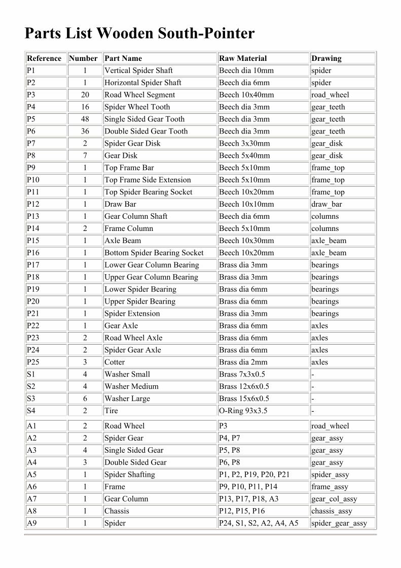
Parts List Wooden South-PointerReference Number Part Name Raw Material DrawingP1 1 Vertical Spider Shaft Beech dia 10mm spiderP2 1 Horizontal Spider Shaft Beech dia 6mm spiderP3 20 Road Wheel Segment Beech 10x40mm road_wheelP4 16 Spider Wheel Tooth Beech dia 3mm gear_teethP5 48 Single Sided Gear Tooth Beech dia 3mm gear_teethP6 36 Double Sided Gear Tooth Beech dia 3mm gear_teethP7 2 Spider Gear Disk Beech 3x30mm gear_diskP8 7 Gear Disk Beech 5x40mm gear_diskP9 1 Top Frame Bar Beech 5x10mm frame_topP10 1 Top Frame Side Extension Beech 5x10mm frame_topP11 1 Top Spider Bearing Socket Beech 10x20mm frame_topP12 1 Draw Bar Beech 10x10mm draw_barP13 1 Gear Column Shaft Beech dia 6mm columnsP14 2 Frame Column Beech 5x10mm columnsP15 1 Axle Beam Beech 10x30mm axle_beamP16 1 Bottom Spider Bearing Socket Beech 10x20mm axle_beamP17 1 Lower Gear Column Bearing Brass dia 3mm bearingsP18 1 Upper Gear Column Bearing Brass dia 3mm bearingsP19 1 Lower Spider Bearing Brass dia 6mm bearingsP20 1 Upper Spider Bearing Brass dia 6mm bearingsP21 1 Spider Extension Brass dia 3mm bearingsP22 1 Gear Axle Brass dia 6mm axlesP23 2 Road Wheel Axle Brass dia 6mm axlesP24 2 Spider Gear Axle Brass dia 6mm axlesP25 3 Cotter Brass dia 2mm axlesS1 4 Washer Small Brass 7x3x0.5 -S2 4 Washer Medium Brass 12x6x0.5 -S3 6 Washer Large Brass 15x6x0.5 -S4 2 Tire O-Ring 93x3.5 -
A1 2 Road Wheel P3 road_wheelA2 2 Spider Gear P4, P7 gear_assyA3 4 Single Sided Gear P5, P8 gear_assyA4 3 Double Sided Gear P6, P8 gear_assyA5 1 Spider Shafting P1, P2, P19, P20, P21 spider_assyA6 1 Frame P9, P10, P11, P14 frame_assyA7 1 Gear Column P13, P17, P18, A3 gear_col_assyA8 1 Chassis P12, P15, P16 chassis_assyA9 1 Spider P24, S1, S2, A2, A4, A5 spider_gear_assy

Copyright ODTS 2003
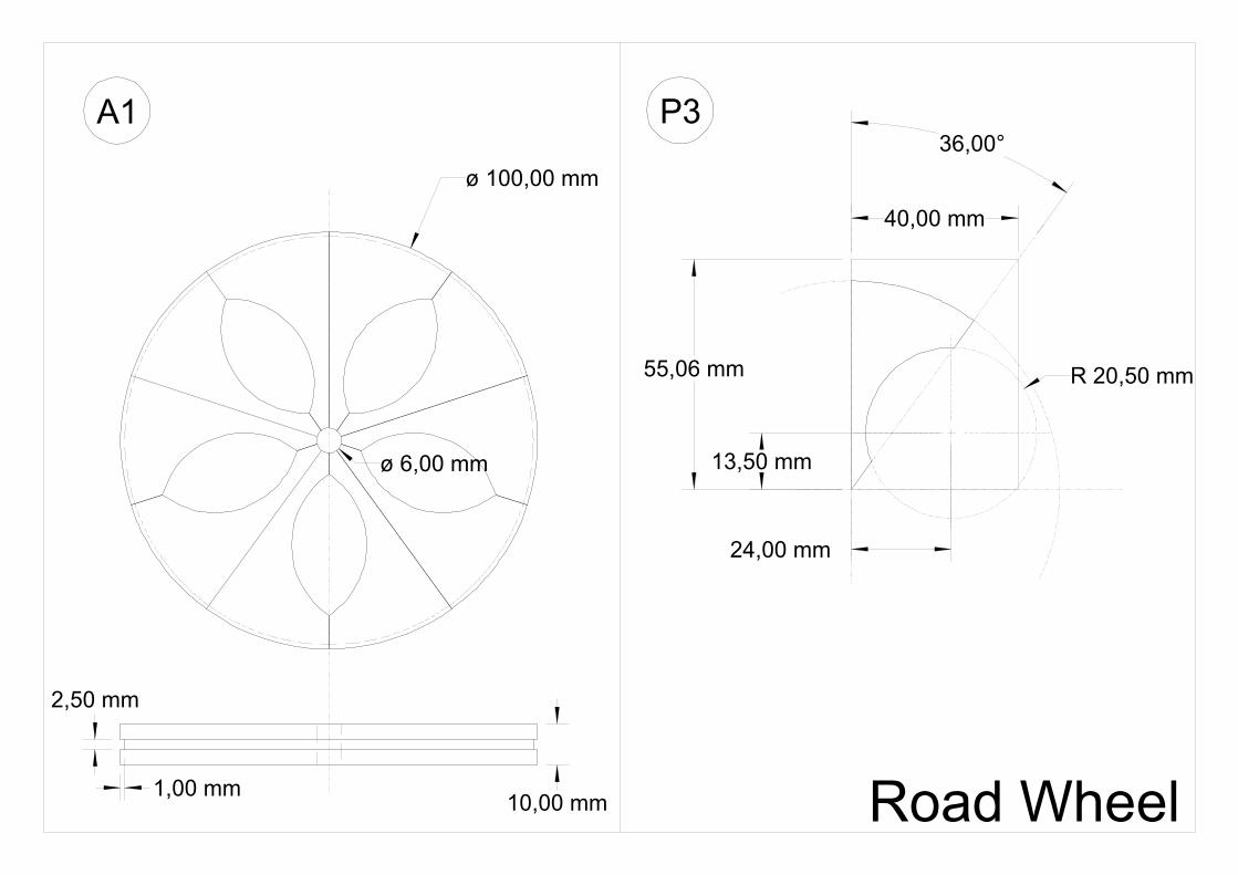
P1 Vertical Spider Shaft The cross bore must be true and exactly in the middle. It helps to drill it first and cut the shaft to length afterwards. For the end bores a lathe is the tool best suited. P2 Horizontal Spider Shaft A simple lathe job again, length must be accurate. P3 Road Wheel Segment Fundamental theory behind my construction was the concept of radial grain: For maximum strength the wood’s grain has to run lengthwise from hub to rim of the wheels. As the widest beech profile obtained was 40mm, ten parts are needed per wheel. To make so many identical parts efficiently some jigs are recommended. Sawing jig: The angle of 36° must be kept very accurately, otherwise there will be ugly gaps in the wheels. I nailed two rails onto a board, which in turn was clamped to the saw table. Thus I could offer the 40x10mm profile to the saw blade at 36° and 90° alternatingly. The triangles are then g lued together in pairs along the second longest edge, resulting in wedges with 72° included angle. Let dry thoroughly! Carving jig: If you use a hole-cutter for the cavities, nail two rails with 72° included angle to another board and fix this to the boring table. It is then a question of patience to adjust the drill center to the specified point (M in the math part at the end of this booklet). Then the cutter is mounted, the wedge held firmly between the rails and the first cut taken, but only to a depth of 5mm! (Cutting all through would produce very ragged edges on the down side) Flip the wedge over and repeat for other side. Do this for all wedges. Then re-adjust the drill to the mirrored center. Again cutting to a depth of 5mm should remove the circle segments cleanly. Work through all wedges. Next put a grinding drum with a diameter well below 40mm into the drill and grind the cavities to a smooth finish. For very ambitious workers a final touch with a 40mm grinding drum is recommended. But be careful not to burn the wood! P4, P4, P6 Gear Teeth Select the best beech rods you can find: straight grain, hard fiber, exact diameter. Put a stop in the tailstock chuck and part off to correct length on the lathe. A little sanding paper cares for rounded edges. P7, P8 Gear Disk Find a hole-cutter with sufficient inner cavity and fix a 3mm polished steel rod instead of the center drill. Drill 3mm holes into the beech profiles, switch to the hole -cutter, thread the steel rod through the hole and cut half through the wood. Flip over and finish cut. (You could use a fretsaw as well, if you have the time…). Next chuck a piece of metal in the lathe and drill and tap M3 down its center. Screw in a M3 stud (silver steel rod with threads cut from both ends). Move to the rotary table, drill a piece of wood scrap 3mm, thread on the stud, followed by one or more gear disks and bolt down with washer and nut. Take care to avoid thread-marks inside the bores! Then index and drill the required holes, stopping in the scrap wood of course. It may be a good idea to take a new 3mm wood drill for this job.

Copyright ODTS 2003
When all holes are done, move everything back to the lathe and turn down the disks to the specified external diameter and shape. Take care to cut into the wood, not out of it: Move the saddle towards the chuck into the wood until the cutting edge is 2mm from the end of the cut. Retract tool, move past the wood, then forward again and finally cut the remaining 2mm by moving the saddle back towards the tail stock. P9, P10, P11 Frame Top Parts Cut from beech profile, but do not drill the holes yet. P12 Draw Bar Cut from beech bar. For the square hole, drill 5mm first and open up with a square needle file. P13 Gear Column Shaft Simple turning job, holes must be concentric. P14 Frame Column Cut from beech profile. Make all ends equal and adapt holes/slots in P9 and P12 accordingly. P15, P16 Axle Beam Parts Cut from beech profile. Do not drill holes yet! P17 – P21 Bearings Chuck brass rod in lathe, polish up a bit and part off to size. P22, P23 Axles The cross holes must be true. Drill them first, then chuck rod in lathe, polish and part off both ends to size. P24 Spider Gear Axle There is not much room left between Spider Gear and Gear Column Shaft. The hub must be very flat therefore. The parts can either be turned from 6mm rod or soldered up (soft solder suffices) from 3mm rod and 6mm pipe. A1 Road Wheel Now for the fun part: Take five wedges and glue them up to one wheel. If there are any gaps, don’t worry. Some grinding down the inner or outer flats on the wedges will correct the error easily. Try to spread the corrective measures over all wedges evenly to maintain a symmetrical appearance. Let the glue dry very well. Next sand and polish down both sides of both wheels. Mount a faceplate onto the lathe and bolt a wheel to it, putting some packing under the wheel to let the lathe tool reach the entire rim in one setup. Adjust until a needle in the tailstock chuck points to the middle of the wheel. Drill and ream for 6mm.

Copyright ODTS 2003
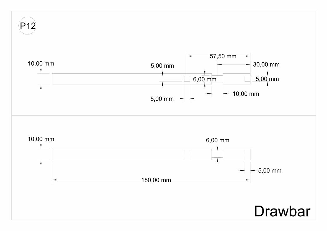
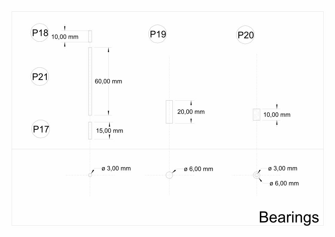
Put a knife tool onto the saddle and turn down the wheel to 100mm diameter, taking shallow cuts and working from the edge to the middle. Do not let the steel cut outward over the edge, it will splinter badly (see P7). Finish with sanding paper. For the grooves use a parting off tool. A2, A3, A4 Gears Depending on the dimensional accuracy of your raw material and drill bits, the teeth are either pressed in or secured with some superglue. Avoid white glue as its water content tends to disfigure the teeth. Adjust teeth to protrude 5mm evenly. I piled washers 5mm high, put the gear on it teeth down and hammered everything home. The bore in the bigger gears needs widening. I chucked them in the lathe and opened up using a 6mm ball ended mill. Ream 6mm apart from the two A3 gears needed for A7. A5 Spider Shafting Glue P2 into P1, with exactly equal ends protruding both sides, using white glue. When dry, insert P19 and P21 and fix with superglue. Finally mount P20. A6 Frame Glue P10 to P9 at right angles and P11 centrally on top. Let dry. Put flat on table (P11 on top) and mark out the two holes, using the exact center distance of 25mm (see P10). Drill 3mm, then widen the hole in P11 to 6mm and 4mm all through. Glue in the columns P14 at right angles. A7 Gear Column Press/Glue the two gears A3 to column P13. Watch out for the direction of the teeth! The gear disks must be flush with the ends of the column. When the column is turned between fingers, no wobble of the gears shall be present. Otherwise correct the bores in the gears and reassemble. Finally super-glue the bearings P17 and P18 into their respective holes. A8 Chassis Glue bar P12 into the slot of beam P15. Is the square hole vertical? The top surfaces must be flush. Then close the remaining notch with part P16 glued in. Let dry thoroughly. Grab the assembly in the vice and mark out the three vertical holes, centered in the middle of P15 and with distance 25mm both sides (see P15). Drill 3mm 10mm deep. Then open up the correct (!) two of them to 6mm. Mark out the centers of the ends of P15 and drill 6mm 15mm deep. Take care that these holes are at right angles to the three vertical bores. A9 Spider Ream holes in A2 until the gears run smoothly on axles P24. Assemble S1 and A2 in pairs to A5 by pressing in P24. Use superglue inside A5 if necessary.

Copyright ODTS 2003
Ream bores in A4 until they run smoothly on the bearings of A5. Assemble, not forgetting S2 in between. A10 Final Assembly Ream holes in A1 and A3 until they run smoothly on P23. Press P25 into P23, thread through S3 and A1, put some white glue on A1 and press A3 on top. Let dry, then ream out any glue which may have entered the bore. Make sure the sandwiches still run easily on their axles. Assemble to A8 by pressing in P23, not forgetting S3. Use superglue inside A8 if necessary. Remove the wheels again by pressing out P25. Ream bore of A4 until it revolves freely on P22, assemble to A8 by pressing/gluing P22 into A8 with cotter P25 and washer S3 in place. Ream the remaining holes in A8 and A6 until the respective bearings on A7 and A9 turn freely (if no reamer is available, polish down the bearings a bit). Assemble S1, S2, A7 and A9 in the only working order and hold everything together by plugging in A6. I would prefer a steel pin in A8 to any glue, should A6 be to loose in its sockets (mine is an interference fit). Put O-rings on wheels, wheels back on axles, cotters back in and you are done! Maintenance Great care was taken to have all sliding interfaces between brass and wood only. No oil or grease is required. The only trouble you may encounter is bores getting tight through humidity or warping gear disks. As long as A6 can be removed from A8, everything can be taken apart and all bores re-reamed. Should the cotters get loose, fix them with Loctite retaining formula – or any household adhesive, which will not stick to brass too firmly. Have fun!

Spider
P1
ø 10,00 mmø 6,00 mm
ø 3,00 mm
ø 6,00 mm
12,50 mm
25,00 mm 30,00 mm
ø 6,00 mm
ø 3,00 mm
5,00 mm
10,00 mm
10,00 mm
P2
Road Wheel
ø 100,00 mm
24,00 mm
13,50 mm
R 20,50 mm
36,00°
55,06 mm
2,50 mm
1,00 mm 10,00 mm
ø 6,00 mm
A1 P3
40,00 mm

Gear Teeth
ø 3,00 mm
8,00 mm 10,00 mm 15,00 mm
P4 P5 P6

Gear Disks
AA
A-A
ø 33,00 mm
ø 25,00 mm
ø 3,00 mm
ø 6,00 mm
5,00 mm
AA
A-A
ø 25,00 mm
ø 3,00 mm
3,00 mm
ø 17,00 mm
1,50 mm
P8 P7

Frame Top
60,00 mm
5,00 mm
10,00 mm
10,00 mm
5,00 mm
ø 4,00 mm ø 4,00 mm
ø 3,00 mm
10,00 mm
35,00 mm
10,00 mm10,00 mm
2,50 mm 2,50 mm
10,50 mm
ø 6,00 mm
20,00 mm
10,00 mm
5,00 mm 5,00 mm
5,00 mm
P10P9 P11
Drawbar
5,00 mm
5,00 mm
6,00 mm
10,00 mm
30,00 mm57,50 mm
5,00 mm180,00 mm
5,00 mm
6,00 mm
10,00 mm
10,00 mm
P12

Columns
57,00 mm
10,00 mm
5,00 mm
84,00 mm
5,00 mm
ø 3,00 mm
ø 6,00 mm
10,00 mm
5,00 mm
5,00 mm
5,00 mm
P13 P14

Axle Beam
20,00 mm
83,00 mm
6,00 mm
50,00 mm
10,00 mm18,00 mm
11,00 mm
10,00 mm
5,00 mm
ø 6,00 mmø 3,00 mm
8,00 mm
10,00 mm
20,00 mm
ø 6,00 mm
2,00 mm
10,00 mm
21,50 mm
6,00 mm
10,00 mm 10,00 mm
10,00 mm10,00 mm
15,00 mm
P15 P16
Bearings
ø 3,00 mm ø 3,00 mmø 6,00 mm
ø 6,00 mm
10,00 mm20,00 mm
15,00 mm
60,00 mm
10,00 mmP18
P21
P17
P19 P20

Axles
ø 3,00 mmø 6,00 mm
ø 6,00 mm
ø 2,00 mm
14,00 mm2,00 mm
15,00 mm
19,00 mm
34,00 mm
3,00 mm
3,00 mm
ø 2,00 mm
P23
P22
P24 P25

Gear Assembly
5,00 mm5,00 mm
5,00 mm
P4 P5 P6
P7 P8
A2 A3 A4

Spider Shafting Assembly
A5
P21
P19
P20
P1
P2

Frame Assembly
A6
P14
P14
P9
P10
P11

Gear Column Assembly
A7
A3
A3
P13
P18
P17

Chassis Assembly
A8
P12
P16
P15

Spider Assembly
A9
A5
S2
S1
P24
A2A2
A4
A4
S2
S1
P24

Final Assembly
A8
S3
P23
A1
A3
P25
S3
A7
A6
A9
A4
P22
S2
S3
S1
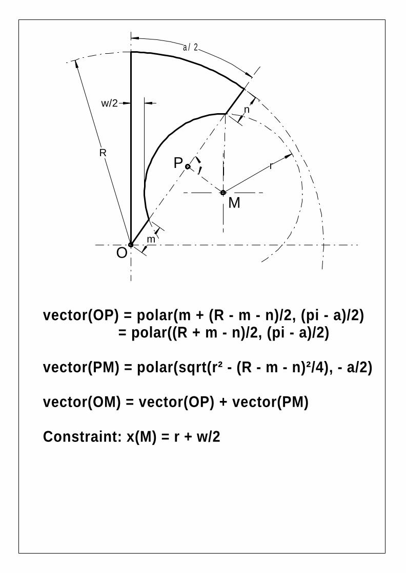
Rr
a/2
n
m
w/2
P
M
O
vector(OP) = polar(m + (R - m - n)/2, (pi - a)/2) = polar((R + m - n)/2, (pi - a)/2)
vector(PM) = polar(sqrt(r² - (R - m - n)²/4), - a/2)
vector(OM) = vector(OP) + vector(PM)
Constraint: x(M) = r + w/2
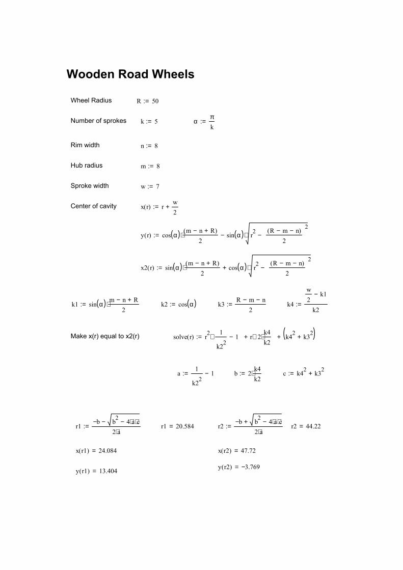
y r1( ) 13.404= y r2( ) 3.769−=
x r2( ) 47.72=x r1( ) 24.084=
r2 44.22=r2b− b2 4 a⋅ c⋅−+
2 a⋅:=r1 20.584=r1
b− b2 4 a⋅ c⋅−−2 a⋅
:=
c k42 k32+:=b 2k4k2
⋅:=a1
k221−:=
solve r( ) r21
k221−
⋅ r 2
k4k2
⋅⋅+ k42 k32+( )+:=Make x(r) equal to x2(r)
k4
w2
k1−
k2:=k3
R m− n−2
:=k2 cos α( ):=
Wooden Road Wheels
Wheel Radius R 50:=
Number of sprokes k 5:= απk
:=
Rim width n 8:=
Hub radius m 8:=
Sproke width w 7:=
Center of cavity x r( ) rw2
+:=
y r( ) cos α( ) m n− R+( )2
⋅ sin α( ) r2R m− n−( )
2
2−⋅−:=
x2 r( ) sin α( ) m n− R+( )2
⋅ cos α( ) r2R m− n−( )
2
2−⋅+:=
k1 sin α( ) m n− R+2
⋅:=

Copyright ODTS 2003