WM, Tractor, Tiller, Lawn mower, EHP 182208, Update ...
32
2002 SERVICE UPDATE INFORMATION HOME PRODUCTS
Transcript of WM, Tractor, Tiller, Lawn mower, EHP 182208, Update ...

2002 SERVICEUPDATE INFORMATION
H O M E P R O D U C T S

2
NOTES

3
TABLE OF CONTENTS
Steering changes for Lawn Tractors 4
Fuel Tanks / Seat inprovements 6
Brake Adjustments 7
DLT Transmission installation / Freewheel Rod/ Control Linkage 8
DLT reverse Pedal / LT Belt Guide / GT Assist Spring change 9
Electrical Components Improvements 10
Electrical Components Quick Reference 11
Tractor Electricdal Troubleshooting Basics 12
Tiller Improvements 17
48” Mower Baffle 18
48” Deflector / Blade Bolt Torque / Nose Roller Kit 19
Changes to the Two Bin Bagger 20
EZ Walk Mowers - Drive Cable Adjustment 21
EZ Walk Drive Pinion 22
EZ Walk Drive Pinion - Gearbox - Blade Adapter 23
EZ Walk Drive Cable Replacement 24
EZ Walk Drive Belt Replacement 26
HONDA Blade Brake Clutch 27
Changes to: Electric Start - Grass Catcher - Drive Wheels 28
Changes to: High Wheel Trimmers - Front Gear Drive Mowers 29
Blade List 30

4
NEW LAWN TRACTOR STEERING
A new steering system was phased in during 2001on lawn tractors. The new steering system issmoother and requires less effort to turn the steer-ing wheel. The assembly mount is held by fourself tapping screws from the underside. A washeris placed on the steering shaft and is retained bythe steering clip.NOTE: The new steering cannot be used to re-place the old steering system because the chasisare made differently.
ASSEMBLY MOUNT
GEAR SHOULDER BOLT
OLD STEERINGASSEMBLY
STEERING CLIP
STEERING CLIP

5
PARTS FOR NEW LAWN TRACTOR STEERING
Key Part Number Description Notes1 175146 ASY - MOUNT - complete Requires 1751182 175118 BOLT-SHOULDER-GEAR NOT included with 1751463 175553 CLIP, Steering - Spring - 3/4"4 121749X WASHER .781ID X 1.0OD X 16GA 5 17060612 SCREW, 3/8 -16 X 3/4" Self Tapping5 17060616 SCREW, 3/8 -16 X 1.0" Self Tapping Also mounts drive belt keeper
DRAGLINKS used with new LT Steering6 175121 DRAGLINK - 15" FRONT WHEEL .LT.20016 175122 DRAGLINK - 16" FRONT WHEEL .LT.2001
MY2001 Steering Parts used with LT HOOD7 177876 Shaft-Assembly - 17.8" LENGTH - Thru-hole dia .3318 153720 EXTENSION-STEERING, uses bolt - 3/8-16 threaded hole9 74780520 5/16-18 X 1.25" Bolt GR 8
10 73800500 5/16-18 HEX LOCKNUT
MY2002 Steering Parts used with LT HOOD7 180641 Shaft-Assembly - 17.8" LENGTH - End with dia .265 thru hole8 180640 EXTENSION-STEERING, uses locknut - Double D with 1/2-20 Threaded End9 71130420 1/4-28 X 1.25" Bolt - Grade 8
10 73540400 1/4-28 NUT Crown Lock
Steering Parts used with STEALTH / DLT / LARGE HOOD7 177883 Shaft Steering - 23.4" LENGTH - Double D with 1/2-20 Threaded End
NEW LAWN TRACTOR STEERING
NEW STEERING OLD STEERING
5
2
1
7
4
3
8
109
5
5
6
Replaces this Steering System on LawnTractors

6
There will be a transition to a new seat system this year. The new seat will have two shoulder bolts thatwill slide in two slots in a new wider seat pan. Because of the wider seat pan, the seat pivot bracket willbe wider. The old seat pan had one slot and two tracks allowing the seat to slide forward and backward.
NEW SEATOLD STYLE SEAT(2001 & Before)
ONE SLOT
SHOULDER BOLTS
NEW SEAT MOUNTING
LARGER FUEL TANKS ON DELUXE MODELS
NewlargerFuelCap
The Operator can view the fuel level in rear tankthrough the fender for 2002. Garden Tractors willhave 5 gallon tanks. DLT models will have 4gallon rear tanks.
7
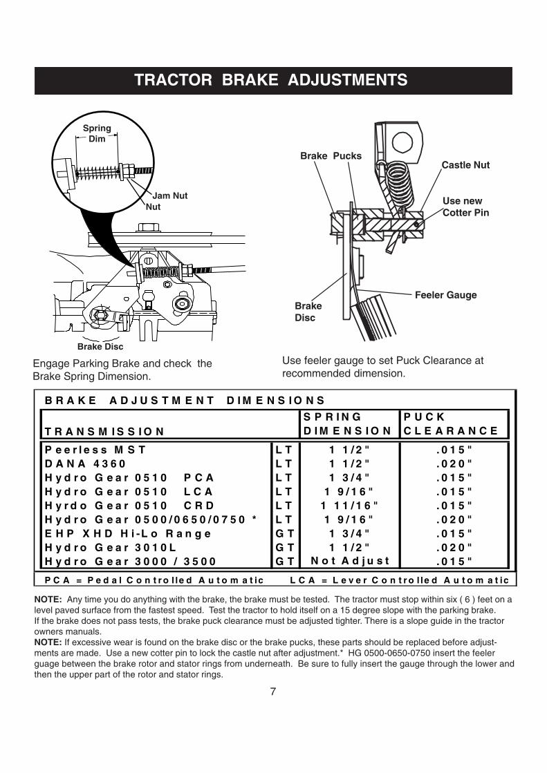
TRACTOR BRAKE ADJUSTMENTS
NOTE: Any time you do anything with the brake, the brake must be tested. The tractor must stop within six ( 6 ) feet on alevel paved surface from the fastest speed. Test the tractor to hold itself on a 15 degree slope with the parking brake.If the brake does not pass tests, the brake puck clearance must be adjusted tighter. There is a slope guide in the tractorowners manuals.NOTE: If excessive wear is found on the brake disc or the brake pucks, these parts should be replaced before adjust-ments are made. Use a new cotter pin to lock the castle nut after adjustment.* HG 0500-0650-0750 insert the feelerguage between the brake rotor and stator rings from underneath. Be sure to fully insert the gauge through the lower andthen the upper part of the rotor and stator rings.
B R A K E A D J U S T M E N T D I M E N S I O N S
T R A N S M I S S I O NS P R I N G D I M E N S I O N
P U C K C L E A R A N C E
P e e r l e s s M S T L T 1 1 / 2 " . 0 1 5 "D A N A 4 3 6 0 L T 1 1 / 2 " . 0 2 0 "H y d r o G e a r 0 5 1 0 P C A L T 1 3 / 4 " . 0 1 5 "H y d r o G e a r 0 5 1 0 L C A L T 1 9 / 1 6 " . 0 1 5 "H y r d o G e a r 0 5 1 0 C R D L T 1 1 1 / 1 6 " . 0 1 5 "H y d r o G e a r 0 5 0 0 / 0 6 5 0 / 0 7 5 0 * L T 1 9 / 1 6 " . 0 2 0 "E H P X H D H i -L o R a n g e G T 1 3 / 4 " . 0 1 5 "H y d r o G e a r 3 0 1 0 L G T 1 1 / 2 " . 0 2 0 "H y d r o G e a r 3 0 0 0 / 3 5 0 0 G T N o t A d j u s t . 0 1 5 "
P C A = P e d a l C o n t r o l le d A u t o m a t ic L C A = L e v e r C o n t r o l le d A u t o m a t ic
Brake Pucks
Feeler Gauge
Castle Nut
Use newCotter Pin
Use feeler gauge to set Puck Clearance atrecommended dimension.
Engage Parking Brake and check theBrake Spring Dimension.
SpringDim
NutJam Nut
Brake Disc
BrakeDisc

8
DLT PEDAL AUTOMATIC REVERSE COMPLAINTSDLT tractors with Pedal Control Automatic mayhave complaints of slow reverse or no reverseif the correct installation procedure is not used.Tighten fasteners in this sequence:
Loosely assemble all screws or boltsand nuts that hold transaxle.
Tighten the screws labeled 1 that holdthe transaxle to the Torque Strap.
Tighten the screws labeled 2 that holdthe Torque Strap to the Chasis.
Tighten the nuts and bolts labeled 3that hold the axle supports to the rearmounting brackets.
DLT FREEWHEEL CONTROL ROD
NOTE: If this procedure does not increase the reverse speed. Use a straight edge to check the TorqueStrap. If there is a severe bow toward the rear, the transaxle is located too far rearward.
2001FREEWHEELROD SPRING
2002 DLTFREEWHEELROD SPRING
BYPASSVALVE
The attachment of the spring on the Freewheel Control Rod to the Bypass Valve has been improved onDLT tractors. The end of the spring is formed differently and a 179422 washer and 4497H retainerspring now retain it to the Bypass Valve.
The linkage going from the Foot Pedals to the Automatic Transaxle control arm was retained with 4497HRetainer Springs. If improperly installed, the 4497H can keep the linkage from the full range ofmovement needed. The tractor may not go as fast in forward or reverse as it can. In 2002 a change ismade to a 178062 Clip so it cannot be installed improperly.
IMPROPERINSTALLATION PROPER
INSTALLATION NEW 178062 CLIP
DLT AUTOMATIC PEDAL LINKAGE
CASTLE NUT
3
12
2
TORQUESTRAP

9
The 179433 Reverse Pedal now comes with thePedal , Pedal Cover, and the Screw installed. Oneshoulder bolt under the footpad can be removedand used to install a new reverse pedalassembly.
Changes have been made to improve the belt guideon the 6 speed lawn tractor transaxles. The guideis now closer to the pulley to better retain the beltand improve belt disengagement characteristics.To identify the belt guides, the loop for the screwthat retains the belt guide is in the reversedirection on the 178394. The previous number was173898.
GARDEN TRACTOR LIFT ASSIST SPRING CHANGE
The Lift Assist Spring Assembly on GardenTractors will now be part of the Sleeve Hitch Kit,beginning in 2002. A slot has been added to thebracket on the Lift Shaft. The end of the spring ishooked into the slot . A bolt, nut , and washer arethen installed to hold the assist spring in the properposition. The bracket at the other end of the springwill need to be attached to the chasis. Completeinstructions will be included in the Sleeve HitchKit.
LT BELT GUIDE CHANGES
LOOP ON PREVIOUS173898 BELT GUIDE
178394 BELT GUIDE
LIFT SHAFT ASSEMBLY
CARRIAGEBOLT
FLAT WASHERLOCK NUT
FORWARD ENDOF LIFT ASSISTSPRING
REVERSE PEDAL
SHOULDER BOLT
DLT REVERSE PEDAL IMPROVEMENT
10
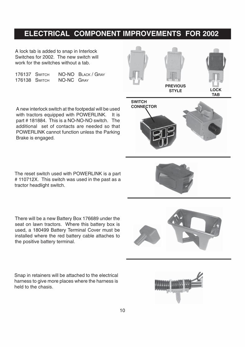
ELECTRICAL COMPONENT IMPROVEMENTS FOR 2002
A lock tab is added to snap in InterlockSwitches for 2002. The new switch willwork for the switches without a tab.
176137 SWITCH NO-NO BLACK / GRAY
176138 SWITCH NO-NC GRAY
A new interlock switch at the footpedal will be usedwith tractors equipped with POWERLINK. It ispart # 181884. This is a NO-NO-NO switch. Theadditional set of contacts are needed so thatPOWERLINK cannot function unless the ParkingBrake is engaged.
The reset switch used with POWERLINK is a part# 110712X. This switch was used in the past as atractor headlight switch.
There will be a new Battery Box 176689 under theseat on lawn tractors. Where this battery box isused, a 180499 Battery Terminal Cover must beinstalled where the red battery cable attaches tothe positive battery terminal.
Snap in retainers will be attached to the electricalharness to give more places where the harness isheld to the chasis.
SWITCHCONNECTOR
LOCKTAB
PREVIOUSSTYLE

11
Ign
itio
n S
wit
ch
Ign
itio
n K
ey
Hal
og
en H
ead
ligh
t A
ssy
Inte
rlo
ck S
wit
ch
Inte
rlo
ck S
wit
ch
Am
met
er (
15
Am
p )
1639
68 -
-> 1
7556
6
( del
ta )
17
5448
16
1343
-->
176
137
1095
53X
1
2282
2X
7 te
rmin
als
/ DE
LTA
( p
last
ic )
14
0401
D
LT
tra
cto
rs o
nly
N
O /
NO
- s
nap
-in
N
O /
NC
scr
ews
Am
met
er (
DL
T-D
GT
)
snap
- in
ge
neric
cov
er
( 20
01 &
new
er p
rodu
ct )
B
lack
/ G
ray
Gra
y 17
5548
Ign
itio
n S
wit
ch
Ign
itio
n K
ey
Hea
dlig
ht
So
cket
(sm
all)
In
terl
ock
Sw
itch
In
terl
ock
Sw
itch
st
ud w
ith n
uts
5 te
rmin
als
/ DE
LTA
( p
last
ic )
( d
elta
)
1752
42
1536
64--
> 1
7613
810
9869
X
1775
00
1755
67
- N
o H
eadl
ight
s 14
0403
tw
o te
rmin
als
-
N
O /
NC
- s
nap
-in
NC
/ s
crew
s -
sp
ade
conn
ecto
rs
snap
- in
C
rafts
man
cov
er
( bu
lb 7
152J
)(2
001
& n
ewer
)
Gra
y G
ray
Ro
un
d
Ig
niti
on
Sw
itch
Ig
nit
ion
Key
H
ead
ligh
t S
ock
et (
larg
e)
Inte
rlo
ck S
wit
ch
Inte
rlo
ck S
wit
ch
Ju
mp
er W
ire
158
913
-
( in
dak
)
1487
09
1818
84
10
4445
X
14
0844
- (
amm
eter
)
5 te
rmin
als
/ Ind
ak (
die
cast
) 10
9310
X
two
term
inal
s -
NO
-NO
-NO
-G
ray-
Sn
ap-i
n
N
O /
scre
ws
Sw
itch
- P
OW
ER
LIN
K
Gra
y P
last
ic B
ack
Cra
ftsm
an c
over
(
bulb
715
2J )
2001
& b
efor
e P
OW
ER
LIN
K o
nly
11
0712
X
Ig
nit
ion
Sw
itch
Ig
nit
ion
Key
H
ead
ligh
t S
ock
et
Inte
rlo
ck S
wit
ch
Inte
rlo
ck S
wit
ch
Tac
ho
met
er
1403
01 -
( in
dak
)
1639
96
1662
99 f
or
CR
D
1803
79 f
or
CR
D
1818
33
7 te
rmin
als
/ Ind
ak (
diec
ast)
12
2147
X
Ste
alth
Hoo
d on
ly
NO
/ sc
rew
s / s
pri
ng
ten
sio
n N
O -
Sn
ap-i
n
DL
T -
DG
T o
nly
term
inal
s in
pyr
amid
ge
neric
cov
er
( bu
lb 7
152J
)
-
Bla
ck -
R
ound
(ne
w 2
002)
Ign
itio
n S
wit
ch
Ign
itio
n K
ey
Dia
gn
ost
ic J
um
per
Kit
P
TO
Sw
itch
( 7
ter
min
als)
S
eat
Sw
itch
H
ou
rmet
er (
DL
T-D
GT
)
268
3R
( d
elta
)
1508
34
1549
63 -
Red
Kn
ob
1607
84 -
17
5549
ana
log
5 te
rmin
als
/ Ind
ak (
diec
ast)
17
5447
(
dia
gn
ost
ic t
oo
l )
1694
17 -
Bla
ck K
nob
N
O -
Oliv
e G
reen
sp
ade
conn
ecto
rs
Bat
tery
Igni
tion
/ O
NA
N
RE
D D
LT C
over
reta
iner
RE
QU
IRE
D
Sea
t S
wit
ch
1775
01di
gita
l
Ign
itio
n S
wit
ch
NU
T, I
gn
Sw
, (D
elta
) T
erm
inal
Co
nn
ecto
r K
it
1404
05 -
Ret
ain
er, S
wit
ch
1213
05X
4
pin
conn
ecto
r
std
3654
02
/ 44
06R
14
5774
(P
last
ic)
1486
91
will
NO
T w
ork
if 8
ter
min
als
NC
- G
ray
Ho
urm
eter
(re
ctan
gu
lar)
5 te
rmin
als
/ Ind
ak (
diec
ast)
N
UT
, Ig
n S
w, (
Ind
ak)
( p
arts
to
rep
air
har
nes
s )
m
.y. 2
000
and
bef
ore
16
9635
Whi
te p
last
ic b
ack
1242
11X
(P
last
ic)
PT
O S
wit
ch (
8 t
erm
inal
s )
Rel
ay
Ho
urm
eter
Bra
cket
Ign
itio
n S
wit
ch
C
OV
ER
, Ig
n S
w N
ut
1746
51 -
Red
Kn
ob
10
9748
X
1696
39
s
td 3
6540
1 14
1226
(R
ubbe
r)
17
4652
- B
lack
Kn
ob
Ho
lder
, Rel
ay
Wir
e Lo
op
scre
ws/
Inda
k /d
ieca
st
So
len
oid
20
AM
P F
use
17
4653
- Y
ello
w K
no
b
1729
89
1419
40 -
( h
ou
rmet
er )
(Del
co S
tart
er G
ener
ator
) 17
1141
1751
58 (
Yel
low
)
1404
05 -
Ret
ain
er, S
wit
ch
Bat
tery
Bo
x -
LT
C
ove
r, T
erm
inal
(Red
)
Bat
tery
Cab
le T
erm
inal
S
ole
no
id K
it
30 A
MP
Fu
se
will
wo
rk f
or
7 te
rmin
als
1766
89
1315
63 -
So
len
oid
1486
98
1461
54
1088
24X
( G
reen
)
new
fo
r 20
01
Use
180
449
Cov
er
1804
49 -
Bat
tery

12
If the fuse is blown, only replace it with the correct fuse. Lawn Tractors with a 15 AMP fuse can use a 20 AMP fuse.Garden Tractors use 30AMP fuse (green).Lawn Tractors use 20 AMP fuse (yellow).
Check condition of battery case?
Check for good battery connections?
Is the battery clean?
If the battery is 12.3 - 12.6 DC Volts, thebattery is acceptable for normal use.
If voltage is 12.6 DC Volts or more thebattery is fully charged.
Check battery for D.C. voltage?
Always wear eye protectionwhen working with a battery.You should also wear plasticgloves and apron when incontact with the battery.
Correct any problems found with wiresor connectors. Look at the terminals inthe connector and the switch to see ifthe connector is correctly located onthe switch.
CAUTION: Do not wear watches or jewelry while working near electrical components.
If the case is cracked or leaking acid,properly discard battery with due care.
If the connections are bad or corroded,you will not get a consistent supply ofelectricity. Use a scraper and a wirebrush to clean the terminals. Afterinstalling the cables on the batteryterminals, apply a non-metallic greaseto both to reduce new corrosion.
If the battery is dirty, it will leakelectrical current and slowly discharge.Use a paper towel to clean the batterycase with baking soda and water.
Check the fuse.
Go to tests for electricalgrounds on the next page.
TRACTOR ELECTRICAL TROUBLESHOOTING BASICS
START HERE If the battery is 11.7 to 12.2 DC Volts,the battery needs to be charged.��Check electrical charging system
on page 13 .
If the battery is below 11.7 DC Volts,the battery may be good. However, itis not cost effective to charge and testwhile on an outside service call.Replace the battery. Dischargedbatteries are not covered by warranty.
Check electrical connectors and wires.Are any wires damaged or hanging loose?Are connectors plugged in the properway?

13
TRACTOR ELECTRICAL TROUBLESHOOTING BASICS
Electrical Grounds are necessary tomake a complete electrical path so acircuit can function. Use an electricalmeter for this check.
If you get a reading greater than0.5 OHMS, you will need to track downthe poor connection. Start at thebattery cable and check componentsgoing toward the item that is notworking. When you find a place wherethe resistance increases, you have aplace where an electrical connectionmust be improved.
If you get a reading of 0.5 OHMS orless grounds are good, you can stop.
Hold the other meter probe to a cleanmetallic surface on the item that isnot functioning.
Hold one meter probe to the negativebattery post.
Move the selector on your meter to theOHMS or R X 1 position. Connect theleads to the meter for OHMS.
A reading of more than 0.5 OHMSindicates a poor ground that resists thepassage of electricity. You will need toimprove the connections between parts toget the resistance to electrical passagebelow 0.5 OHMS. Do this by scrapingwhere electrical contact is made betweenparts, until the finish is bright metallic.EXAMPLE: Where the eyelet for the blackbattery cable meets the chassis.
Check electrical charging system.
Start engine, raise engine to fastestRPM for two full minutes.Check voltage at battery.
With engine off check the battery voltage. Note the DC Voltage reading.
START HERE
Move selector on meter to DC Voltsor scale for 12 DCV. Place leads inpositions for Voltage.
START HERE
If the DC Voltage reading is thesame as the reading noted with theengine off, the charging systemis not working, or is not connected tothe battery. Refer to electricalsection of engine manufacturer’smanual to further diagnose chargingsystem.
If the reading is above 12.8 DC Volts,the charging system is working.Discontinue charging tests.
If the tractor has relays, test the relayson page 16. If any of the relays test bad,replace the relay and test the chargingsystem again. In some wire harnesses,a relay makes an electrical connectionbetween the engine charging systemand the battery.
NOTE: There are two starwashers usedto cut through the paint to make a goodground. One is at one of the screws thatholds the engine to the chassis. Theother is where the black battery cable isheld the chassis.
14
TRACTOR ELECTRICAL TROUBLESHOOTING BASICS
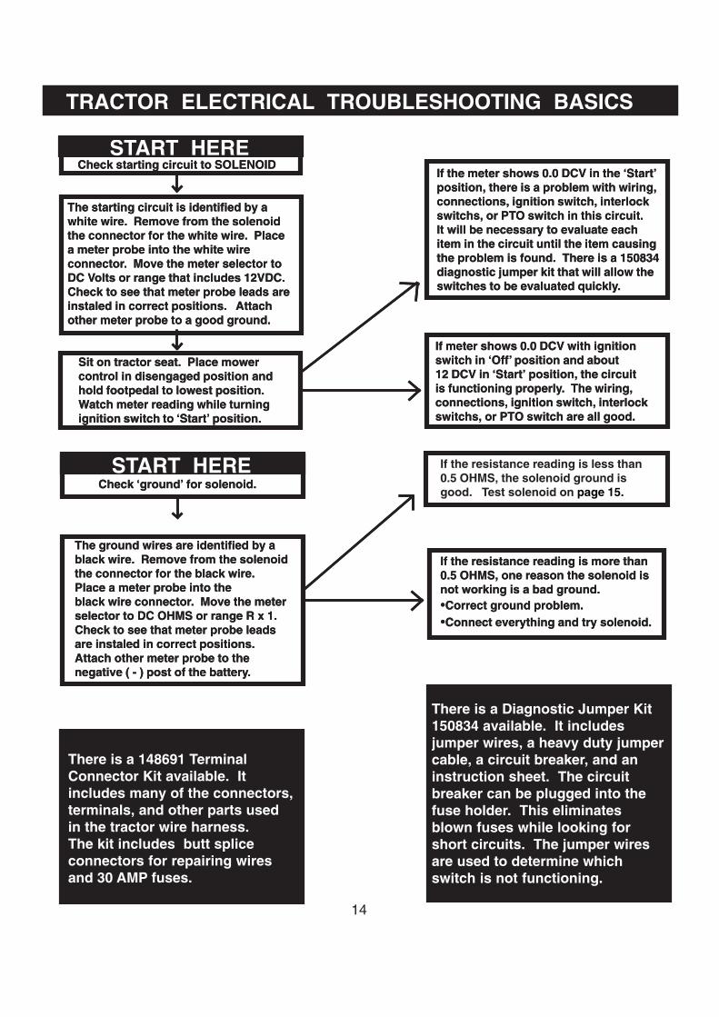
START HERECheck starting circuit to SOLENOID
The starting circuit is identified by awhite wire. Remove from the solenoidthe connector for the white wire. Placea meter probe into the white wireconnector. Move the meter selector toDC Volts or range that includes 12VDC.Check to see that meter probe leads areinstaled in correct positions. Attachother meter probe to a good ground.
Sit on tractor seat. Place mowercontrol in disengaged position andhold footpedal to lowest position.Watch meter reading while turningignition switch to ‘Start’ position.
If meter shows 0.0 DCV with ignitionswitch in ‘Off’ position and about12 DCV in ‘Start’ position, the circuitis functioning properly. The wiring,connections, ignition switch, interlockswitchs, or PTO switch are all good.
If the meter shows 0.0 DCV in the ‘Start’position, there is a problem with wiring,connections, ignition switch, interlockswitchs, or PTO switch in this circuit.It will be necessary to evaluate eachitem in the circuit until the item causingthe problem is found. There is a 150834diagnostic jumper kit that will allow theswitches to be evaluated quickly.
If the resistance reading is less than0.5 OHMS, the solenoid ground isgood. Test solenoid on page 15.
There is a 148691 TerminalConnector Kit available. Itincludes many of the connectors,terminals, and other parts usedin the tractor wire harness.The kit includes butt spliceconnectors for repairing wiresand 30 AMP fuses.
There is a Diagnostic Jumper Kit150834 available. It includesjumper wires, a heavy duty jumpercable, a circuit breaker, and aninstruction sheet. The circuitbreaker can be plugged into thefuse holder. This eliminatesblown fuses while looking forshort circuits. The jumper wiresare used to determine whichswitch is not functioning.
The ground wires are identified by ablack wire. Remove from the solenoidthe connector for the black wire.Place a meter probe into theblack wire connector. Move the meterselector to DC OHMS or range R x 1.Check to see that meter probe leadsare instaled in correct positions.Attach other meter probe to thenegative ( - ) post of the battery.
START HERECheck ‘ground’ for solenoid.
If the resistance reading is more than0.5 OHMS, one reason the solenoid isnot working is a bad ground.�Correct ground problem.�Connect everything and try solenoid.
TRACTOR ELECTRICAL TROUBLESHOOTING BASICS
START HERECheck starting circuit to SOLENOID
The starting circuit is identified by awhite wire. Remove from the solenoidthe connector for the white wire. Placea meter probe into the white wireconnector. Move the meter selector toDC Volts or range that includes 12VDC.Check to see that meter probe leads areinstaled in correct positions. Attachother meter probe to a good ground.
Sit on tractor seat. Place mowercontrol in disengaged position andhold footpedal to lowest position.Watch meter reading while turningignition switch to ‘Start’ position.
If meter shows 0.0 DCV with ignitionswitch in ‘Off’ position and about12 DCV in ‘Start’ position, the circuitis functioning properly. The wiring,connections, ignition switch, interlockswitchs, or PTO switch are all good.
If the meter shows 0.0 DCV in the ‘Start’position, there is a problem with wiring,connections, ignition switch, interlockswitchs, or PTO switch in this circuit.It will be necessary to evaluate eachitem in the circuit until the item causingthe problem is found. There is a 150834diagnostic jumper kit that will allow theswitches to be evaluated quickly.
There is a 148691 TerminalConnector Kit available. Itincludes many of the connectors,terminals, and other parts usedin the tractor wire harness.The kit includes butt spliceconnectors for repairing wiresand 30 AMP fuses.
There is a Diagnostic Jumper Kit150834 available. It includesjumper wires, a heavy duty jumpercable, a circuit breaker, and aninstruction sheet. The circuitbreaker can be plugged into thefuse holder. This eliminatesblown fuses while looking forshort circuits. The jumper wiresare used to determine whichswitch is not functioning.
The ground wires are identified by ablack wire. Remove from the solenoidthe connector for the black wire.Place a meter probe into theblack wire connector. Move the meterselector to DC OHMS or range R x 1.Check to see that meter probe leadsare instaled in correct positions.Attach other meter probe to thenegative ( - ) post of the battery.
START HERECheck ‘ground’ for solenoid.
If the resistance reading is more than0.5 OHMS, one reason the solenoid isnot working is a bad ground.�Correct ground problem.�Connect everything and try solenoid.

15
Step # 1.
1. Place meter probes on battery terminals. Ifthe reading is 12.2 VDC or more, proceedto the next step. If the reading is below12.2 VDC, charge or replace the battery withone that has at least12.2 V DC.
Step # 2.
1. Connect negative (black) meter lead to thebattery negative (-) terminal.
2. Connect the positive (red) meter lead to the‘hot’ terminal of the solenoid.
3. Note the voltage reading.
Step # 3.
1. Keep the meter selector in the sameposition and the negative meter leadconnected to the battery negative terminal.
2. Connect the positive (red) meter lead to theend of the cable normally connected to thestarter motor.
3. Engage the parking brake and turn theignition switch to the “START” position.
4. Note the voltage reading.5. If the voltage drop is more than 0.50 VDC
between the two noted readings, thesolenoid or the starter cable is suspect.Replace the solenoid.
6. Re-install the red cable to the starter motor.If the solenoid checks acceptable and thestarter does not crank, check for clean tightbattery connections and check the groundsfor the battery and the engine.
· Remove the red cable from the engine starter motor before testing.· Place digital meter selector on D.C. Voltage scale that includes 13 Volts.
TRACTOR ELECTRICAL TROUBLESHOOTING BASICS
DIAGNOSIS OF STARTER SOLENOIDS
B
A
A
12.6
(+)
(-)
B
12.4
(+)
(-)

16
Test # 1, Coil Resistance1. Set meter to Ohm’s scale2. Attach leads to Relay terminals 85 and 86.3. There are two relays:if the number 49400 is
on the relay it is 1998 or newer and shouldread 68-82 Ohms. Relays with a Hella logowere made before 1998 and should read80-90 Ohms.
Test # 2, Continuity when energized1. Attach a 12 DC volt power source to Relay
terminals 85 and 86.2. Set meter to continuity test or Ohm’s scale.3. Check for continuity between Relay
terminals 30 and 87; then 30 and 87a.4. You should have continuity between
terminals 30 and 87 only when the relay isenergized. If you have continuity between30 and 87a when energized, the relay isdefective.
Test # 3, Continuity when NOT energized1. Remove the power source from relay
terminals 85 and 86.2. Check for continuity between Relay
terminals 30 and 87; then 30 and 87a.3. You should have continuity between
terminals 30 and 87a only.
85 86
3087
87A
Remove Relay from harness connector beforetesting.
DIAGNOSIS OF ELECTRICAL RELAY 109748X
TRACTOR ELECTRICAL TROUBLESHOOTING BASICS
87
87A86 85
30RELAY
78.4
87
87A86 85
30RELAY
00.0
87
87A86 85
30RELAY
00.0

17
TILLER CHANGES FOR 2002
Front tine tillers with reverse will now have a cablethat operates the reverse mechanism instead of asteel rod linkage. This will result in smoother moretrouble free operation.
REVERSE IDLERARM ASSEMBLY
REVERSE CABLE
Transmission cases for CRT and DRT tillers havebeen improved for 2002. There will now be ashoulder bolt to maintain the opening for the depthstake. This will keep the case opening wide enoughso depth stake will easily move up and down.
DEPTH STAKE
SHOULDER BOLT
DEPTH STAKEASSEMBLY
The Depth Stake Assembly will now be fastenedto the pallet with two screws. In the past the depthstake was cradled in packaging materials.Customers sometimes lost the assembly when theythrew out the carton packaging materials. The twobolts and nuts used to assemble the depth stakeassembly to the tiller frame will be in the parts bag.
SCREWS

18
BAFFLE ADDED TO 48” MOWER
WELDED BAFFLE
A welded baffle has been added to the front of the 48” mower housing to improve the grass blowoutcharacteristics. This welded baffle will be found on production decks begining in 2002. If there is acomplaint about grass blowout on a deck without the welded baffle, use the 180487 Baffle Kit below.
LOCK NUT
HEX BOLT
HEX BOLT
WASHER
LOCK NUT
Remove and Discard theexisting 5/16 Carriage
SIDE
BAFFLE
Use this kit for 2001 production 48” mowerswhere the customer complains of grassblowout from the front of the deck.
48 INCH BAFFLE KIT NO. 180487

19
ROD
BRACKET ‘A’
BRACKET ‘B’
NOSE ROLLER
The nose roller kits have been improved. Thereis now a rod between the brackets to supportthe nose roller. The brackets in the kit are nowlabeled ‘A’ and ‘B’ to help the customer toidentify to which welded deck bracket eachshould be attached.
48” MOWER DEFLECTOR
The new 48” mower deck deflector is stiffer,heavier, and the hinge area has been rein-forced. It is possible to identify the improvedpart if there are ribs above the ‘48’ on the topof the deflector. The original deflector did nothave ribs.
OLDDEFLECTOR
TRACTOR MOWER BLADE BOLTBlade bolts should always be torqued to the properrange. For the 7/16 GR 8 Bolts (5/8” wrench) usedon 48” mowers torque to 45-55 Foot Pounds. Thefactory bolt 174365 must be used because theremust be a recesed area in the washer. For the3/8 x 24 GR 8 Bolts (9/16” wrench) used on othertractor mowers torque to 30-40 Foot Pounds.
174365 BOLT ASSEMBLYUSED ON 48” MOWER
OTHER NOTES ON TRACTOR MOWERSNew 180054 Blade for mulching and bagging on 48” mower will reduce grass blowout.
New 180808 mower secondary belt on 48” deck will have increased life.
The primary mower belt is changed to 148763 on the 50” deck for 2002. This is a larger beltcross section already in use on the 48” mower deck. The pulleys and idlers are different fromthose used on previous 50” decks in past years. If the wrong belt is used, the belt may seeextreme wear in a short time.
NEWDEFLECTOR
RIBS
NOSE ROLLER DESIGN IMPROVED

20
IMPROVEMENTS FOR TWO BIN 38” & 42” BAGGERS Improvements will make the installation of thetwo bin bagger easier than ever on Lawn Trac-tors with 38” and 42” mower decks. There will nolonger be a pin to locate the post to the bracketas the two will be welded into a Support Assem-bly. The assembly is positioned with the bracketholes over four shoulder bolts in the drawbar.When the assembly slides down into place thereis a Stop Bracket that locks into place. You willneed to hold the Stop Bracket out of the Drawbarwith a fingernail while removing the SupportAssembly from the tractor. Extra shoulder boltsare shipped with baggers for older tractors thatdo not have shoulder bolts installed into the draw-bar from the factory.
DRAWBARPOST
BRACKET
SUPPORT ASSEMBLYSHOULDER BOLTS
STOPBRACKET
The Cover Assembly is positioned behind thetractor with the tubular bagger frame latched intoplace inside the cover. It is suggested that cus-tomers find another person to help install thisassembly. There is a channel in the front andmiddle of the Cover Assembly that will slip overthe top of the Post. The grass containers used with all the baggershave been re-tooled. It will be easier to assemblethe upper and lower container sections.
COVER ASSEMBLYPOST
FOR 2-BIN AND 3-BIN BAGGERS
THIS KIT IS PROVIDED FOR BAGGERS WITH LOOSE LOCKING COVERS. FOR BETTER LOCKING OF THE BAGGERCOVER DURING OPERATION, REPLACE THE END CAP ON THE CENTER SUPPORT TUBE WITH THE END CAP INTHIS KIT. TWO END CAPS ARE PROVIDED FOR THE 3-BIN BAGGER ATTACHMENT.
2-BIN BAGGER 3-BIN BAGGER
BAGGER END CAP KIT - Part Number 174695
CHANNELOPENING
End CapPart No. 174083

21
EZ WALK MOWERS - NEW FOR 2002
There is an EZ Walk drive system for both frontdrive and rear drive mowers for 2002. The EZWalk system allows the customer to control thespeed of the self propel system using a drivecontrol lever in front of their right hand. When thedrive control lever is released the mower stops.As the operator holds down the operator presencecontrol bar and pulls the drive control lever, themower self propel starts to drive. The tighter theoperator pulls the drive control lever toward thehandle, the faster the mower goes up to maximumspeed. Both front drive and rear drive models have21” cutting paths.The transmission access is thesame as other rear drive and front drive modelsfor the last few years. Some areas with whichyou will need to familiarize yourself are:
Drive Cable Adjustment procedureDrive Cable Replacement procedureDrive pinion operation and servicing
FRONT DRIVE
DRIVE CONTROL LEVER
OPERATOR PRESENCE BAR
REAR DRIVE
DRIVE CONTROL LEVER
OPERATOR PRESENCE BAR
DRIVE CABLE ADJUSTMENTOver time, the drive control system maybecome “loose”, resulting in a decrease in speed.There is a button on the underside of the drive controlhousing to increase tension on the drive cable.Proceed as follows:1. With engine ‘off’, disconnect spark plug wire
from spark plug.2. Pull drive control lever ALL THE WAY BACK to
the handle.3. Push button on underside of drive control.
While holding button in, return drive controllever to disengaged position, ALL THE WAYFORWARD.NOTE: Do not ratchet the adjustment.
4. Release button.5. Operate mower to test drive speed. If
condition becomes worse after the above steps(forward speed has become slower), yoursystem was not “loose”. Repeating the abovesteps will return your unit to the properadjustment and speed.
6. If condition fails to improve after the above steps(forward speed remains the same), your drivebelt is worn and should be replaced.

22
E Z WALK - DRIVE PINION OPERATIONTo access the Drive Pinion Assembly on the mowerremove the drive wheel. The same Drive Pinionsused on the front drive EZ Walk system are usedon the rear drive EZ Walk system.
DUST COVER
Only the complete Drive Pinion Assembly will beavailable from repair parts . The right side DrivePinion Assembly is part number 176412 and isheld with white plastic wrap. The left side DrivePinion Assembly is part number 176413 and isheld with clear plastic wrap. The plastic wrap isremoved by pulling between the perforations afterthe pinion assembly is installed on the gearboxdrive shaft.
Only the Drive Retainer is different between theright and left side pinion assemblies. These aremirror image parts except for the letter to desig-nate ‘R’ for right or ‘L’ for left.If you have a wheelthat will not drive, first check to see if the drive beltis wet. If not, remove the pinion assemblies andcheck to see if the correct Drive Retainer is onthat side.
HOW IT WORKS: The pinion assemblies aremounted on the gearbox drive shaft. When thereis no power to the gearbox shaft, the Torsion Springholds the Pawl in the disengaged position. Whenthere is power to the gearbox shaft, the frictionbetween the bearing support and the drive discovercomes the Torsion Spring, and the Pawl canengage one of the three TABs inside the PinionGear. You can disassemble these parts to removecontamination. However, be very careful with theTorsion Spring. Any kinks or bends will keep it fromfunctioning properly.
TORSION SPRING
PAWL
TAB
PINION GEAR
BACKSIDE VIEW
FRONTSIDE VIEW
DRIVE RETAINER
TAB
176413LEFT SIDE
176412RIGHT SIDE

23
PINION
TORSION SPRING
DRIVE RETAINER
PAWL
DRIVE DISCFRICTION SEAL
E Z WALK - DRIVE PINION SERVICING
The Drive Pinion Assembly can be disassembledand cleaned of contamination. Remove the PinionAssembly as a complete unit by grabbing the Fric-tion Seal with your fingers, keeping pressure onthe Pinion Gear. This will allow you to inspect theassembly as it was on the mower. When assem-bling, the projection on the Pawl must go into theopening on the Drive Disc.
NOTE: No lubrication should be used on parts of the drive pinion assembly or the system may notdrive. This includes the areas where the Friction Seal touches the Drive Disc and the Pinion Gear.The Friction Seal must set over the bearing support.NOTE: Care must be taken not to change the shape of the Torsion Spring or the pinion will either notdrive or not allow the operator to pull backwards. To increase the durability of the torsion spring, it iszinc plated to reduce corrosion.
NEW GEARBOX FOR FRONT DRIVE E ZWALKThe EZ Walk front drive gearbox appears
similar to gearbox for the rear drive,but is smaller.
174915 GEARBOX
A new 179606 blade adapter is used with the E ZWalk front drive when an engine spacer ring is usedwith Briggs or Tecumseh engines. The differencebetween the blade adapters in use are how far thecrankshaft goes into the adapter. Use of a bladeadapter other than the one specified in the partslisting can cause the mower not to meet standardsfor industry or CPSC.
NEW BLADE ADAPTER FOR FRONT DRIVE E Z WALK
NOTE: Make sure the Drive Disc is completely seated in the Friction Seal.
24
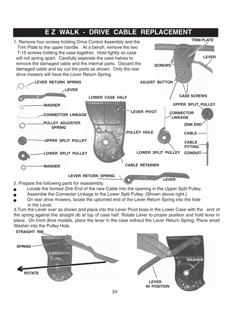
E Z WALK - DRIVE CABLE REPLACEMENT1. Remove four screws holding Drive Control Assembly and the Trim Plate to the upper handle. At a bench, remove the two T-15 screws holding the case together. Hold tightly so case will not spring apart. Carefully seperate the case halves to remove the damaged cable and the internal parts. Discard the damaged cable and lay out the parts as shown. Only the rear drive mowers will have the Lever Return Spring.
LEVER
TRIM PLATE
SCREWS
CASE SCREWS
ADJUST BUTTON
LOWER CASE HALF
LEVER PIVOT
CABLE RETAINER
2. Prepare the following parts for reassembly.Locate the formed Zink End of the new Cable into the opening in the Upper Split Pulley.Assemble the Connector Linkage to the Lower Split Pulley. (Shown above right.)On rear drive mowers, locate the upturned end of the Lever Return Spring into the hole
in the Lever.3.Turn the Lever over as shown and place into the Lever Pivot boss in the Lower Case with the end ofthe spring against the straight rib at top of case half. Rotate Lever to proper position and hold lever inplace. On front drive models, place the lever in the case without the Lever Return Spring. Place smallWasher into the Pulley Hole.
PULLEY HOLE
CABLEFITTING
CABLE
ZINK END
UPPER SPLIT PULLEY
CONNECTOR LINKAGE
LOWER SPLIT PULLEY CONDUIT
LEVERLEVER RETURN SPRING
STRAIGHT RIB
LEVERIN POSITION
ROTATE
SPRING
WASHER
LEVER RETURN SPRING
LEVER
WASHER
WASHER
CONNECTOR LINKAGE
PULLEY ADJUSTER SPRING
UPPER SPLIT PULLEY
LOWER SPLIT PULLEY
25
E Z WALK - DRIVE CABLE REPLACEMENT
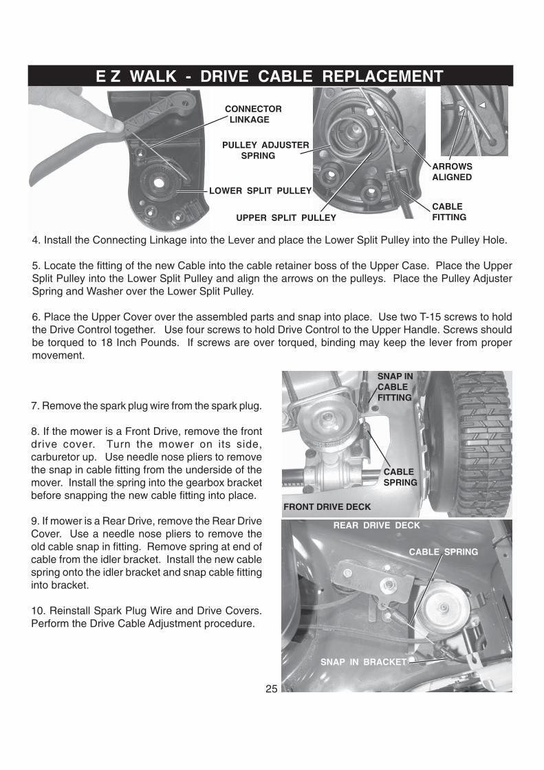
4. Install the Connecting Linkage into the Lever and place the Lower Split Pulley into the Pulley Hole.
5. Locate the fitting of the new Cable into the cable retainer boss of the Upper Case. Place the UpperSplit Pulley into the Lower Split Pulley and align the arrows on the pulleys. Place the Pulley AdjusterSpring and Washer over the Lower Split Pulley.
6. Place the Upper Cover over the assembled parts and snap into place. Use two T-15 screws to holdthe Drive Control together. Use four screws to hold Drive Control to the Upper Handle. Screws shouldbe torqued to 18 Inch Pounds. If screws are over torqued, binding may keep the lever from propermovement.
CONNECTOR LINKAGE
LOWER SPLIT PULLEY
PULLEY ADJUSTER SPRING
ARROWSALIGNED
UPPER SPLIT PULLEYCABLEFITTING
REAR DRIVE DECK
SNAP IN BRACKET
CABLE SPRING
7. Remove the spark plug wire from the spark plug.
8. If the mower is a Front Drive, remove the frontdrive cover. Turn the mower on its side,carburetor up. Use needle nose pliers to removethe snap in cable fitting from the underside of themover. Install the spring into the gearbox bracketbefore snapping the new cable fitting into place.
9. If mower is a Rear Drive, remove the Rear DriveCover. Use a needle nose pliers to remove theold cable snap in fitting. Remove spring at end ofcable from the idler bracket. Install the new cablespring onto the idler bracket and snap cable fittinginto bracket.
10. Reinstall Spark Plug Wire and Drive Covers.Perform the Drive Cable Adjustment procedure.
FRONT DRIVE DECK
CABLESPRING
SNAP INCABLEFITTING

26
1. Remove spark plug wire from spark plug. Removescrew holding belt drive cover and the belt drive cover.
2. Remove nut holding gearbox pulley. Remove upperhalf of Pulley and Drive Belt.
3. Turn mower on side with carburetor up. Removeblade and bottom belt cover. NOTE: Protect your handsfrom sharp edge of blade with work gloves or by wrap-ping blade with protective material.
4. Install new belt on crankshaft pulley and throughopening in deck. Reinstall the bottom belt cover beingcareful to keep belt in crankshaft pulley. Install bladeand torque the blade bolt to 40 Ft.Lbs.
5. Return mower to position with four wheels on ground.Install belt through belt guide onto pulley. Torquepulley nut to 14 to 20 Ft.Lbs. Reinstall drive belt coverand screw. Replace wire on spark plug.
BELTDRIVE COVER
DRIVE BELT BELT KEEPER
GEARBOX DRIVE PULLEY
BELT REPLACEMENT ON E Z WALK FRONT DRIVE
BELT REPLACEMENT ON E Z WALK REAR1. Disconnect the spark plug wire from the spark plugand place where it cannot touch plug.Remove Drive Cover at rear of housing.
2. Remove nut holding gearbox pulley, remove upperhalf of split pulley, and remove Flange Nut holding IdlerAssembly to remove belt.
3. Turn mower on side with carburetor up.RemoveBlade and Bottom Belt Cover.NOTE: Protect yourhands from sharp edge of blade with work gloves orby wrapping blade with protective material.
4. Install new belt on crankshaft pulley and throughopening in deck. Reinstall the bottom belt cover, andblade. Torque the blade bolt to 40 Ft.Lbs.
5. Return mower to position with four wheels on ground.Install Belt onto Pulley and torque pulley nut to 14 to20 Ft.Lbs. Install Washer, Idler Bracket, and FlangeNut. Reinstall drive belt cover. Replace wire on sparkplug.
IDLERASSEMBLY
FLANGE NUT
PULLEY
WASHER( install first )
FLANGE NUT
IDLER BRACKET
( install first )

27
In 2002, HONDA Engines with a HONDA BladeBrake Clutch ( BBC ) will be available on somelawn mowers from EHP. The Blade Bolts are partnumber 180460 ( M10-1.25 x 16 Class 10.9 HexBolt with nylon patch) and should be torqued at36-43 Foot Pounds. A 15 mm socket is recom-mended. The 180459 blade is used with theHONDA BBC. Torque the BBC Bolt at 37 to 43Ft.Lbs.
HONDA ENGINES WITH BLADE BRAKE CLUTCH
REAR DRIVE BELT REPLACEMENT WITH HONDA BBC
The bail is designed to keep the BBC fromactuating when the Operator Presence Bail is notengaged. The offset in the Bail seen here isrequired to meet industry standards. Do not use abail other than the one specified in the partslisting. Test mowers with BBC to see that theengagement control cannot be actuated unlessOperator Presence Bail is against the handle.
BBC BOLT
BLADE BOLT HOLES
SPRING HOLE
BAIL
BBCENGAGEMENT LEVER
OFFSET
BBC SPRING
BBC CABLE
TORQUE LINK
LINK SPRING
DRIVE BELT
To replace the drive belt:1. Remove Spark Plug Wire and secure away from the spark plug.2. Follow directions to remove belt under drive cover on Rear Drive.3. Remove blade using protection from sharp mower blade.4. Remove bottom cover.5. Remove end of BBC Engagement Cable from Blade Brake Clutch.6. Remove Spring from both ends of Torque Link.7. With CAUTION, use a long phillips head screwdriver to push end of Link out of either hole. The spring tension will be released.8. Remove BBC Spring.9. Remove belt around BBC and install new belt.10. Install BBC Spring.11. Position Link and rotate BBC to load spring until you can slide the link into place.12. Reverse numbers 6 to 1. 2002 Model 37779

28
REMOVABLE KEY ON ELECTRIC START
BATTERY BOX
SWITCH
BACK OF HANDLETRIM PLATE
REMOVABLE KEY
NEW ELECTRIC START CONNECTOR ON BRIGGS ENGINES E H PMOWER HARNESS
BRIGGS & STRATTONENGINE HARNESS
GRASS CATCHER IMPROVEMENTNEWSTYLE
OLDSTYLE
Most grass catchers in the past have been heldonto lawn mowers by a wireform. On some mod-els, it has been found that a stamped part holdingthe grass catcher onto the mower reduces grassblowout. This change will be made to rear dis-charge lawn mowers where it will reduce grassblowout.
180331 KEY
ORANGE ( TO BATTERY )
RED ( TO SWITCH )
BLACK ( TO BATTERY ) TO STARTER MOTOR
CHARGING
ZONE CONTROLINTERLOCK SWITCH
DRIVE WHEELS AND DUST COVERSNEW WHEELDUST COVER RIB
OLD STYLE WHEELDUST COVER RIB
The drive wheels and dust covers have beenchanged for 2002. The position of the dust coverrib in the wheel has moved from next to the gearteeth to the very outside diameter of the hub,against the tread. This will require the dust coverto be 1/4” larger in diameter. The new Dust Cover180504 must be used with the new wheels.
TREADHUB
Some customers have complaintsabout batteries or battery chargers.Battery chargers should beconnected to the battery and a goodAC power source. Some customershave trouble finding the batterylocation.

29
NEW GEARBOX - SINGLE SPEED FRONT GEARDRIVEA new gearbox with a plastic case will be used on
2002 single speed front gear drive mowers. Thisgearbox will be serviceable as an assembly.Thesame belt, pulley, and cable will be used as withthe transmission with aluminum gearcase.
DRIVE ENGAGEMENT CONTROL ON FGD MOWERSThere is a new Drive Engagement Control for singlespeed frontwheel gear drive mowers. The new leverwill be distinctively different from the one used in thepast. In addition, an improved conduit will be used.The conduit will be vinyl with two reinforcing wiresmolded in parallel to the cable. This will better resistthe damage from improperly folded handles see onthe previously used conduit with wound reinforcing wire.
CONDUIT
HIGH WHEEL TRIMMER CUTTER BALL SCREW
The screw holding the ball to the spindle has beenimproved. The new screw part number 180334has a recessed hex head with washer. The pre-viously used screw had an allen head and aseperate washer. Both parts are 1/4” x 20 andthe new part can be used in place of the old screw.
HIGH WHEEL TRIMMER SKIRT
180334
PREVIOUS SCREW
SKIRT
There will no longer be a replaceable skirt on the high wheel trimmer shield . The shield will be madelarger to include the area of the skirt.
NEW SHIELD
30
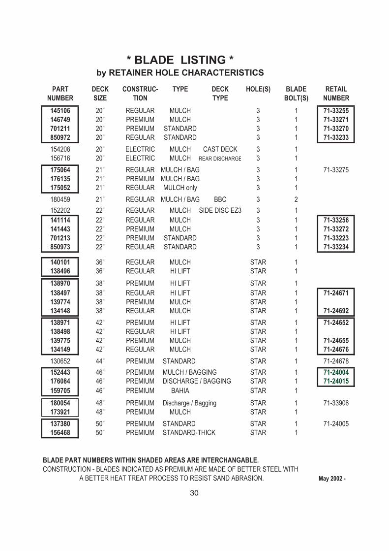
* BLADE LISTING *by RETAINER HOLE CHARACTERISTICS
PART DECK CONSTRUC- TYPE DECK HOLE(S) BLADE RETAILNUMBER SIZE TION TYPE BOLT(S) NUMBER145106 20" REGULAR MULCH 3 1 71-33255146749 20" PREMIUM MULCH 3 1 71-33271701211 20" PREMIUM STANDARD 3 1 71-33270850972 20" REGULAR STANDARD 3 1 71-33233154208 20" ELECTRIC MULCH CAST DECK 3 1156716 20" ELECTRIC MULCH REAR DISCHARGE 3 1175064 21" REGULAR MULCH / BAG 3 1 71-33275176135 21" PREMIUM MULCH / BAG 3 1175052 21" REGULAR MULCH only 3 1180459 21" REGULAR MULCH / BAG BBC 3 2152202 22" REGULAR MULCH SIDE DISC EZ3 3 1141114 22" REGULAR MULCH 3 1 71-33256141443 22" PREMIUM MULCH 3 1 71-33272701213 22" PREMIUM STANDARD 3 1 71-33223850973 22" REGULAR STANDARD 3 1 71-33234
140101 36" REGULAR MULCH STAR 1138496 36" REGULAR HI LIFT STAR 1138970 38" PREMIUM HI LIFT STAR 1138497 38" REGULAR HI LIFT STAR 1 71-24671139774 38" PREMIUM MULCH STAR 1134148 38" REGULAR MULCH STAR 1 71-24692138971 42" PREMIUM HI LIFT STAR 1 71-24652138498 42" REGULAR HI LIFT STAR 1139775 42" PREMIUM MULCH STAR 1 71-24655134149 42" REGULAR MULCH STAR 1 71-24676130652 44" PREMIUM STANDARD STAR 1 71-24678152443 46" PREMIUM MULCH / BAGGING STAR 1 71-24004176084 46" PREMIUM DISCHARGE / BAGGING STAR 1 71-24015159705 46" PREMIUM BAHIA STAR 1180054 48" PREMIUM Discharge / Bagging STAR 1 71-33906173921 48" PREMIUM MULCH STAR 1137380 50" PREMIUM STANDARD STAR 1 71-24005156468 50" PREMIUM STANDARD-THICK STAR 1
BLADE PART NUMBERS WITHIN SHADED AREAS ARE INTERCHANGABLE.CONSTRUCTION - BLADES INDICATED AS PREMIUM ARE MADE OF BETTER STEEL WITH
A BETTER HEAT TREAT PROCESS TO RESIST SAND ABRASION. May 2002 -

31
NOTES

182208 MADE IN THE USA