WLAN Connection Establishment Application Note · CCK: Complementary Code Keying . Introduction...
15
WLAN Connection Establishment Application Note Products: | R&S CMW500 | R&S CMW290 | R&S CMW270 For establishing a WLAN connection be- tween R&S CMW and device under test (DUT), the WLAN properties at the R&S CMW have to be adapted to the test conditions. These can vary in several as- pects, particularly due to the different WLAN standards and characteristics of the DUT. This document describes the critical parameters and provides step-by- step procedures for the configuration. Application Note Klaus Lienhart 12.2015-1C106_1e
Transcript of WLAN Connection Establishment Application Note · CCK: Complementary Code Keying . Introduction...

WLAN Connection Establishment
Application Note
Products:
| R&SCMW500
| R&SCMW290
| R&SCMW270
For establishing a WLAN connection be-
tween R&S CMW and device under test
(DUT), the WLAN properties at the
R&S CMW have to be adapted to the test
conditions. These can vary in several as-
pects, particularly due to the different
WLAN standards and characteristics of
the DUT. This document describes the
critical parameters and provides step-by-
step procedures for the configuration.
App
licat
ion
Not
e
Kla
us L
ienh
art
12.2
015-
1C10
6_1e

Contents
1C106_1e Rohde & Schwarz WLAN Connection Establishment 2
Contents
1 Introduction ............................................................................ 3
2 Test Setups ............................................................................. 5
3 Selected Configuration Topics ............................................. 7
3.1 Power ............................................................................................................. 7
3.2 Standard, Frequencies ................................................................................. 8
3.3 Advanced ...................................................................................................... 9
4 Procedures ........................................................................... 11
4.1 Connection Setup with the R&S CMW as AP ..........................................11
4.2 Determining the Expected Peak Envelope Power...................................13
4.3 Connection Setup with the R&S CMW as Station ...................................13
5 Required Options ................................................................. 14

Introduction
Power
1C106_1e Rohde & Schwarz WLAN Connection Establishment 3
1 Introduction
Connection establishment at the R&S CMW is controlled by the WLAN Signaling appli-
cation.
WLAN Standards
The figure shows the WLAN standards for 20 MHz channels which are relevant for this
document and the mapping onto the “Standard” parameter of the WLAN Signaling ap-
plication. Note that some “Standard” values cover more than one WLAN standard.
11 Mbit/s
1 Mbit/s
2 Mbit/s
5.5 Mbit/s
802.11b
1 Mbit/s
2 Mbit/s
5.5 Mbit/s
11 Mbit/s
6 Mbit/s
9 Mbit/s
12 Mbit/s
54 Mbit/s
802.11a 802.11g
6 Mbit/s
9 Mbit/s
12 Mbit/s
54 Mbit/s
802.11n
6.5 Mbit/s
13 Mbit/s
65 Mbit/s
802.11b
„Standard“ in
WLAN Signaling
802.11a 802.11g
802.11g
(OFDM)
802.11g(OFDM)/n
802.11g/n
802.11n (GF)
802.11a/n 802.11a/n
IEEE Standard
Data Rates
OFDMDSSS, CCK DSSS, CCKOFDM OFDMTransmission Scheme
2.4 GHz 2.4 GHz5 GHzFrequency Band 2.4 GHz, 5 GHz
. . . . . .
. . .
BP
SK
QP
SK
64Q
AM
DB
PS
KD
QP
SK
DQ
PS
KD
QP
SK B
PS
K
BP
SK
QP
SK
64Q
AM
Mod
ulat
ion
MCS0
MCS1
MCS7
Channels 1 – 14 1 – 1436 – 200 1 – 14, 36 – 200
Figure 1: WLAN standards, data rates (20 MHz channels) and mapping on the R&S CMW “Standard”
The 802.11n standard also allows 40 MHz channels not considered here.
OFDM: Orthogonal Frequency Division Multiplex
DSSS: Direct Sequence Spread Spectrum
CCK: Complementary Code Keying

Introduction
Power
1C106_1e Rohde & Schwarz WLAN Connection Establishment 4
Message Sequence for Connection Establishment
Connection establishment between the R&S CMW and the DUT is done automatically
and in the background after the WLAN Signaling application has been started (by
pressing the ON OFF key) – assumed that the parameter settings are correct.
With the R&S CMW in access point mode, the WLAN Signaling application sends bea-
con frames which the DUT (acting as station) detects via passive or active scanning
(active scanning includes a Probe Request message from the DUT and a Probe Re-
sponse message from the R&S CMW). Then the usual authentication and association
process takes place. Finally, the R&S CMW assigns an IP address to the DUT using
the DHCP (Dynamic Host Configuration Protocol) mechanism.
CMW
(AP)
DUT
(Station)
Authentication Request
Authentication Response
Association Request
Association Response
CMW
(AP)
DUT
(Station)
DHCP Discover
Acknowledgement
AcknowledgementAcknowledgement
Acknowledgement
Acknowledgement
Acknowledgement
DHCP Offer
DHCP Request
Acknowledgement
Acknowledgement
DHCP Ack
Authentication and Association IP Address Assignment
Figure 2: Message sequence charts
The connection establishment process for the R&S CMW in Station mode is the same
with inverted roles of R&S CMW and DUT.
Beacon Frames
WLAN access points broadcast information required for association via beacon frames.
The beacons are usually sent at the lowest mandatory data rate and in intervals of
102.4 ms. On the R&S CMW (acting in access point mode), the beacon interval can be
changed in multiples of 1.024 ms. The period of 1.024 ms is called Time Unit (TU).
The beacon frames include the SSID (Service Set Identifier, the name of the WLAN ac-
cess point used by the WLAN station for access) and BSSID (Basic SSID) information.
They also contain information about the supported rates, channel numbers, security re-
quirements, time synchronization and more.
If the R&S CMW acts in station mode, the beacons from the DUT (acting as access
point) might be seen in the measurements. Note that the DUT might use different data
rates / modulations for transmitting data frames and beacons.

Test Setups
Power
1C106_1e Rohde & Schwarz WLAN Connection Establishment 5
2 Test Setups The device under test (DUT) is connected to one of the bidirectional RF COM
connectors at the front panel of the R&S CMW. No additional cabling and no external
trigger is needed. The input level ranges of all RF COM connectors are identical.
Conducted Over the air
Figure 3: Test setups
The “Conducted” test setup is the easiest and preferred solution since it avoids power loss by over-the-air radio transmission.
In case of testing over-the-air via antennas, it is recommended to encapsulate the DUT and the RF antenna for the R&S CMW in an RF shielding box. Thereby interference from any WLAN access point and other devices using WLAN or Bluetooth is avoided. The over-the-air RF connection causes a power loss of 15 dB or more compared to the conducted RF connection. The path loss without RF shielding box would be much higher (typically about 30 to 39 dB compared to the conducted RF connection).
Figure 4: R&S CMW-Z10 RF shielding box
Notes on using the R&S CMW-Z10 RF shielding box:
● Position the DUT at the center of the box.
● A small displacement of the DUT in the RF shielding box can result in an additional
external attenuation of about 10 dB.
● The optimum position of the DUT depends on its antenna arrangement. So try out
several DUT positions around the center of the box.
● Close the RF shielding box cover in order to ensure that no interference by other
WLAN devices operating in the same channel can occur.
Test Setups
Power
1C106_1e Rohde & Schwarz WLAN Connection Establishment 6
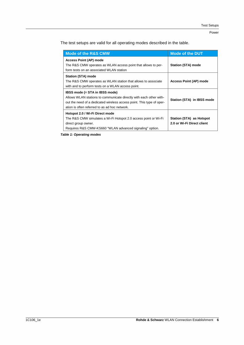
The test setups are valid for all operating modes described in the table.
Mode of the R&S CMW Mode of the DUT
Access Point (AP) mode
The R&S CMW operates as WLAN access point that allows to per-
form tests on an associated WLAN station
Station (STA) mode
Station (STA) mode
The R&S CMW operates as WLAN station that allows to associate
with and to perform tests on a WLAN access point.
Access Point (AP) mode
IBSS mode (= STA in IBSS mode)
Allows WLAN stations to communicate directly with each other with-
out the need of a dedicated wireless access point. This type of oper-
ation is often referred to as ad hoc network.
Station (STA) in IBSS mode
Hotspot 2.0 / Wi-Fi Direct mode
The R&S CMW simulates a Wi-Fi Hotspot 2.0 access point or Wi-Fi
direct group owner.
Requires R&S CMW-KS660 "WLAN advanced signaling" option.
Station (STA) as Hotspot
2.0 or Wi-Fi Direct client
Table 1: Operating modes

Selected Configuration Topics
Power
1C106_1e Rohde & Schwarz WLAN Connection Establishment 7
3 Selected Configuration Topics
3.1 Power
The R&S CMW has the following nominal power limits:
● Maximum nominal transmission power (max. “TX Burst Power”, CMW TX)
– -3 dBm at the RF OUT connector
– -16 dBm at the RF COM connector
● Minimum nominal reception power (min. “RX Burst Power”, CMW RX)
– -50 dBm for BPSK-modulated RF signals
(BPSK is applied for the lowest data rate(s), e.g. 6 and 9 Mbit/s in 802.11a/g)
– -43 dBm for RF signals with higher modulation (QPSK, 16-QAM, …)
See the first figure in chapter “Introduction” for relating the modulation to the standard
and data rate.
For appropriate power settings, the attenuations on the RF transmission path have to
be taken into account. An over-the-air connection via an RF shielding box might intro-
duce an attenuation of about 15 dB or more, for example. Three cases of less power
values than expected have to be payed attention to:
● The R&S CMW acting as WLAN access point provides much less power than a
real WLAN access point (with around 20 dBm). So take care that the attenuations
between R&S CMW and DUT are not too high (use a wire connection if possible)
and that the DUT is configured to receive in the right power range.
● The DUT acting as station might send with too low power in case of high attenua-
tions and modulation modes, leading to a signal strength at the R&S CMW receiver
below its minimum value for accurate signal analysis.
● The expected peak envelope power, which has to be configured on the R&S CMW,
might be set too low if the DUT’s nominal power is accidentally taken for the peak
envelope power (see the following considerations).
Parameters
The default settings of the R&S CMW are sufficient for a successful WLAN association
in many cases. Depending on your DUT and the test conditions, the following parame-
ters of the WLAN Signaling application may need further attention.
● Expected Peak Envelope Power / RX Expected PEP (CMW RX)
Set this parameter to the maximum (not average!) DUT transmit power in dBm. Of-
ten, only the DUT’s nominal or average power is known. In this case, you have to
add the crest factor of 13 dB for WLAN to get the DUT’s maximum transmit power.
Typical values:
– 25 to 35 dBm (i.e. 12 to 23 dBm + 13 dB crest factor) for a conducted RF con-
nection
– 0 to 15 dBm for over-the-air (with RF shielding box) depending on the radio
distance

Selected Configuration Topics
Standard, Frequencies
1C106_1e Rohde & Schwarz WLAN Connection Establishment 8
The expected peak envelope power value is the maximum power level which the
R&S CMW processes. An expected peak envelope power below the actual RF in-
put power causes an over-flow in the input path. A value too much above the RF
input power can reduce the measurement accuracy.
● TX Burst Power (CMW TX)
CMW in Station mode: Make sure that this power is sufficiently high for the DUT to
detect the transmitted signal from the R&S CMW. Typical values:
– -40 dBm for an RF conducted connection
– -16 to -20 dBm for over-the-air transmission (with RF shielding box)
● External Attenuation (for RF Output and RF Input)
These parameters are used to compensate the cable loss and splitter/combiner
loss (if available). The external attenuation is always positive.
If you test over-the-air (with RF shielding box) and you want to compensate the
over-the-air path loss via the external attenuation, then add 15 dB to the external
attenuations and simultaneously set the Expected Peak Envelope Power to 20-
30 dBm and the TX Burst Power to -40 dBm.
3.2 Standard, Frequencies
Parameters
● Standard
Make sure that the DUT supports the selected WLAN standard.
CMW in Station mode: The configured standard must be compatible with the bea-
con format of the DUT (acting as AP).
● Frequency
Make sure that the configured WLAN frequency / channel is within the frequency
band(s) supported by the DUT. The standard and frequency parameters are inde-
pendent at the R&S CMW: There is no automatic restriction of the frequency band
with respect to the selected standard. Some DUTs will not associate if the standard
and frequency do not match.
Frequency Band Carrier Frequencies Channels Standards
2.4 GHz 2412 MHz to 2484 MHz 1 to 14 11b, 11g, 11g/n
5 GHz 5000 MHz to 6000 MHz 36 to 200 11a, 11a/n
Table 2: Frequency bands and standards
CMW in Station mode: The configured WLAN frequency / channel must be the
same as the one selected by the DUT (acting as AP). In the current implementa-
tion, the R&S CMW does not scan the supported frequency range.

Selected Configuration Topics
Advanced
1C106_1e Rohde & Schwarz WLAN Connection Establishment 9
3.3 Advanced
Parameters
● Supported Rates
"Supported Rates" defines the data rate(s) which the R&S CMW supports and con-
sequently which the DUT is allowed to use.
Generally, you can use the default setting (“Supported Rates > User Defined” is
deactivated) which sets the supported rates according to the selected WLAN
standard.
Activate “Supported Rates > User Defined” only if you want to test the DUT with
special supported rates. In case you have activated “… > User Defined”, take the
following considerations into account:
CMW as access point (AP): According to the 802.11 standard, the DUT shall avoid
associating with an access point if it cannot receive and transmit at all mandatory
data rates. This implies two reasonable configuration methods at the R&S CMW:
The first one sets the basic (lowest) data rate and the desired DUT transmission
rate to mandatory for the selected standard (not more rates in order to avoid that
the DUT might change its transmission rate during a test). The second method sets
the data rates from the lowest to the desired DUT transmission rate to mandatory.
Figure 5: WLAN standard and two user defined supported rates

Selected Configuration Topics
Advanced
1C106_1e Rohde & Schwarz WLAN Connection Establishment 10
CMW in Station mode: If the R&S CMW does not include all mandatory rates which the DUT uses for its beacons, the DUT rejects the R&S CMW’s association request. Typically, the mandatory rates for a DUT in AP mode are 1, 2, 5.5, 11 Mbit/s in the 2.4 GHz frequency band and 6, 12 and 24 Mbit/s in the 5 GHz fre-quency band. It is recommended to set these rates as mandatory at the R&S CMW.
If you change the supported rate, you have to disconnect (“Disconnect” hot-
key) and associate the DUT again in order to prompt the DUT to get the new
setting.
Only needed for the R&S CMW in station mode:
● Connection Mode and SSID Connection
Usually, you can keep the default values.
Figure 6: Connection Mode and SSID Connection

Procedures
Connection Setup with the R&S CMW as AP
1C106_1e Rohde & Schwarz WLAN Connection Establishment 11
4 Procedures
4.1 Connection Setup with the R&S CMW as AP
The parameters to be configured are located in the WLAN Signaling application.
Starting steps:
1. Reset the R&S CMW to ensure a definite instrument state.
2. Open the configuration dialog of the WLAN Signaling application via the "Config
…" key in the bottom right corner.
3. Make sure the "Scenario" is set to “Standard Cell”.
4. Set the “Operation Mode” to “AP”.
RF Settings:
5. Select a bidirectional RF connector, for example:
At “RF Output > Routing”: "Connector: RF1COM”
At “RF Input > Routing”: "Connector: RF1COM”
You can keep the default "Converter" values.
Figure 7: RF settings
6. If necessary, also adjust the "External Attenuation" (to compensate a cable loss).
7. Adjust the R&S CMW’s RF output power and the used frequency/channel:
Set "Frequency / Channel" according to your needs
(must be supported by the DUT).
Set the "TX Burst Power" according to your test setup: e.g. -40.00 dBm
The "Bandwidth" is fixed to 20.000 MHz.
8. Set the "Expected Peak Envelope Power" according to the DUT's peak transmis-
sion power: e.g. 30.00 dBm. Notes:
The peak envelope power is about 13 dB (crest factor) above the expected av-
erage power. If the DUT's TX power is given as average value, then add this
13 dB to get the expected peak envelope power.
An over-the-air (with RF shielding box) RF connection between DUT and R&S
CMW reduces the expected peak envelope power by about 15 dB compared
to the RF conducted connection.

Procedures
Connection Setup with the R&S CMW as AP
1C106_1e Rohde & Schwarz WLAN Connection Establishment 12
Connection:
9. Select the “Standard”.
The selected standard must be supported by the DUT and must be consistent with
the “Frequency / Channel” selected under “RF Settings” (no automatic control).
10. The default values for "Beacon Interval", "MAC-Address", "SSID" and the other pa-
rameters in the “Connection” section can be kept.
Final steps:
11. Connect your DUT to the R&S CMW. Use the RF connectors as set in the "RF Set-
tings".
12. Switch on the WLAN Signaling application.
The R&S CMW transmits beacons.
13. On the DUT, turn on WLAN.
The DUT searches for an access point and initiates the connection to it.
14. Observe the "Connection Status" panel in the main view and wait until the DUT
has entered the "Associated" state.
Figure 8: Connection state: Associated
Depending on the DUT it may take a few seconds until the authentication and as-
sociation procedures have finished.
After the DUT has completed its association, the "UE Capabilities" are displayed
on the left side of the main view.
Figure 9: UE capabilities
Checks in Case of Failed Association
● The "TX Burst Power" must be sufficiently high so that the DUT can receive the
transmitted signal.
● The "Expected Peak Envelope Power" must be in accordance with the received
maximum (not average) signal power.
● Make sure that the configured WLAN channel is within the frequency band(s) sup-
ported by the DUT.
● Make sure that the DUT supports the selected WLAN standard.
Procedures
Determining the Expected Peak Envelope Power
1C106_1e Rohde & Schwarz WLAN Connection Establishment 13
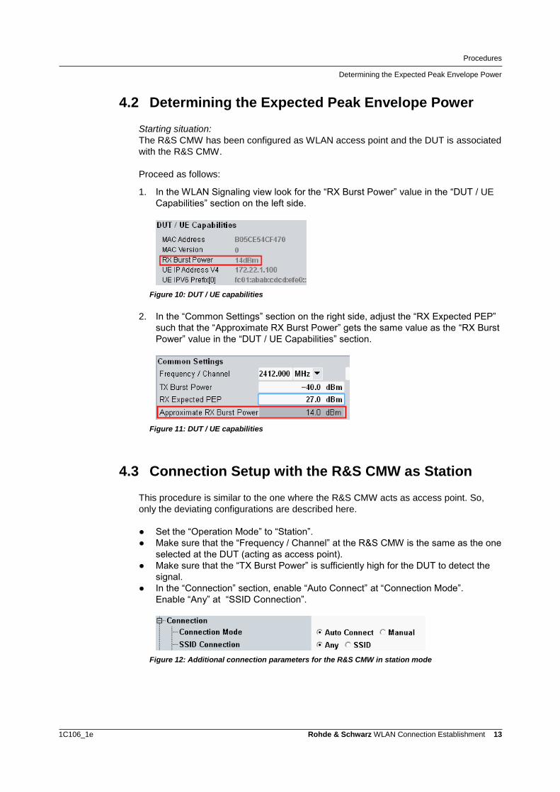
4.2 Determining the Expected Peak Envelope Power
Starting situation:
The R&S CMW has been configured as WLAN access point and the DUT is associated
with the R&S CMW.
Proceed as follows:
1. In the WLAN Signaling view look for the “RX Burst Power” value in the “DUT / UE
Capabilities” section on the left side.
Figure 10: DUT / UE capabilities
2. In the “Common Settings” section on the right side, adjust the “RX Expected PEP”
such that the “Approximate RX Burst Power” gets the same value as the “RX Burst
Power” value in the “DUT / UE Capabilities” section.
Figure 11: DUT / UE capabilities
4.3 Connection Setup with the R&S CMW as Station
This procedure is similar to the one where the R&S CMW acts as access point. So,
only the deviating configurations are described here.
● Set the “Operation Mode” to “Station”.
● Make sure that the “Frequency / Channel” at the R&S CMW is the same as the one
selected at the DUT (acting as access point).
● Make sure that the “TX Burst Power” is sufficiently high for the DUT to detect the
signal.
● In the “Connection” section, enable “Auto Connect” at “Connection Mode”.
Enable “Any” at “SSID Connection”.
Figure 12: Additional connection parameters for the R&S CMW in station mode
Required Options
Connection Setup with the R&S CMW as Station
1C106_1e Rohde & Schwarz WLAN Connection Establishment 14
5 Required Options ● R&S CMW-KS650, "WLAN IEEE 802.11a/b/g basic signaling"
providing basic signaling functionality according to the IEEE standards 802.11a,
802.11b, 802.11g and 802.11g(OFDM)
● R&S CMW-KS651, "WLAN IEEE 802.11n basic signaling"
providing basic signaling functionality according to the IEEE standards 802.11a/n,
802.11g/n, 802.11g(OFDM)/n and 802.11n, 20 MHz SISO

About Rohde & Schwarz
Rohde & Schwarz is an independent group
of companies specializing in electronics. It is
a leading supplier of solutions in the fields of
test and measurement, broadcasting, radio-
monitoring and radiolocation, as well as se-
cure communications. Established more than
75 years ago, Rohde & Schwarz has a
global presence and a dedicated service net-
work in over 70 countries. Company head-
quarters are in Munich, Germany.
Environmental commitment
● Energy-efficient products
● Continuous improvement in environ-
mental sustainability
● ISO 14001-certified environmental
management system
Regional contact
Europe, Africa, Middle East
+49 89 4129 12345
[email protected] North America
1-888-TEST-RSA (1-888-837-8772)
[email protected] Latin America
+1-410-910-7988
[email protected] Asia/Pacific
+65 65 13 04 88
This application note and the supplied
programs may only be used subject to the
conditions of use set forth in the download
area of the Rohde & Schwarz website.
R&S® is a registered trademark of Rohde & Schwarz GmbH & Co. KG; Trade names are trademarks of the owners.
Rohde & Schwarz GmbH & Co. KG
Mühldorfstraße 15 | D - 81671 München
Phone + 49 89 4129 - 0 | Fax + 49 89 4129 – 13777
www.rohde-schwarz.com


![An End-Middle-End Approach to Connection Establishment · An End-Middle-End Approach to Connection Establishment ... and combined with recent NAT traversal techniques, ... TRIAD [20],](https://static.fdocuments.in/doc/165x107/5b0b60737f8b9a61448c965b/an-end-middle-end-approach-to-connection-end-middle-end-approach-to-connection-establishment.jpg)