WL200 - Waterlogic
48
Waterlogic Commercial Products, LLC 3175 Bass Pro Drive Grapevine, TX 76051 (800) 288-1891 www.waterlogicdealers.com Tech Portal Website: techportal.waterlogic.com Waterlogic International, LTD – Global Headquarters Grenfell Road, Maidenhead, Berkshire, SL6 1HN, United Kingdom WL200 MANUAL
Transcript of WL200 - Waterlogic
Waterlogic Commercial Products, LLC 3175 Bass Pro Drive
Grapevine, TX 76051 (800) 288-1891 www.waterlogicdealers.com
Tech Portal Website: techportal.waterlogic.com
Waterlogic International, LTD – Global Headquarters Grenfell Road, Maidenhead, Berkshire, SL6 1HN, United Kingdom
WL200 MANUAL
WL200 Manual Page 2 - Revision: 10-21-21
WL200 MANUAL
Congratulations on your choice of the Waterlogic WL200 Water Treatment System. The WL200 Water Treatment System model dispenses cold water. Every WL200 Water Treatment System includes:
Bio-Cote Anti-Microbial Protection
Filter configuration can be optimized for all water conditions
The Waterlogic WL200 Water Treatment System provides exceptional quality and great tasting water with every use.
INTRODUCTION
Carefully read and follow all instructions to ensure proper and efficient operation of your WL200 Water Treatment System. Contact Waterlogic or an Authorized Waterlogic Dealer if you have any questions. Waterlogic and Authorized Waterlogic Dealers employ trained service personnel who are experienced in the installation, function and repair of Waterlogic equipment. This publication is written for use by these qualified individuals. Waterlogic encourages users to learn about products, however, we believe that product knowledge and service is best obtained by consulting Waterlogic or an Authorized Waterlogic Dealer. Waterlogic water treatment systems should be combined with selected water treatment components to create a system specifically tailored for each application by trained and qualified personnel. Products manufactured and marketed by Waterlogic and its affiliates are protected by patents issued or pending in the United States and other countries. Waterlogic reserves the right to change the specifications referred to in this literature at any time, without prior notice. Changes or modifications not expressly approved by Waterlogic could void the warranty and user’s authority to operate the equipment.
WL200 Manual Page 3 - Revision: 10-21-21
TABLE OF CONTENTS USER GUIDE
• Safety Alert Symbols ................................................................ 4 • Safety Precautions ................................................................... 4 • Features and Benefits .............................................................. 6 • Certifications ............................................................................ 7 • Model Designations and General Specifications ..................... 8 • Electrical and Shipping Specifications ...................................... 9 • Operating Instructions ........................................................... 10 • Warranty ............................................................................... 11
SERVICE GUIDE • Service Requirements ............................................................ 12 • LG Compressor Upgrade ........................................................ 13 • Adjusting Cold Water Set Point ............................................. 14 • Replacement Components (Consumables) ........................... 15 • Countertop Drawings and Parts List ...................................... 16 • Tower Drawings and Parts List……………………......................... 22 • Flow Diagrams ........................................................................ 28 • Electrical Schematics .............................................................. 30
INSTALLATION GUIDE • Pre-Installation Procedures ................................................... 32 • Countertop Draining Procedure ............................................ 35 • Tower Draining Procedure ..................................................... 36 • Installation Instructions ......................................................... 37
TROUBLESHOOTING GUIDE • Power Troubleshooting.......................................................... 39 • Dispense Troubleshooting ..................................................... 41 • Cold Water Troubleshooting .................................................. 48
WL200 Manual Page 4 - Revision: 10-21-21
SAFETY ALERT SYMBOLS
Read and follow all safety information carefully. The signal words used in this manual are selected as shown below and based on an assessment of the degree of potential injury or damage (severe or minor) and the occurrence of injury (definitely occurs or has the potential to occur) when the warning is ignored:
DANGER! Indicates a situation which, when not avoided, results in death or severe injury.
WARNING! Indicates a situation which, when not avoided, has the potential to result in death or severe injury; and/or severe property damage. CAUTION! Indicates a situation which, when not avoided, results or has the potential to result in minor injury; and/or minor property damage.
SAFETY PRECAUTIONS
Basic safety precautions should be followed, including the following: Ensure all Local, State, and Federal Laws and Codes including health and safety guidelines are met when installing Waterlogic Equipment. Only qualified service technicians should attempt installation and service of Waterlogic Equipment. Always read the entire operating instructions before using the appliance and save these instructions for future use.
DANGER! This product can cause death or severe injury if incorrectly operated, installed or maintained. The installation, maintenance, sanitizing and any repair must be performed by qualified persons trained by Waterlogic International or their approved distributors only. Do not remove any panel or cover to protect against electrical shock and exposure to UV radiation.
DANGER! ELECTRICAL SHOCK HAZARD. Always use a dedicated and properly grounded outlet. Unit should be protected by ground-fault circuit interrupter (GFCI) or residual current device (RCD) having a rated residual operating current not exceeding 30mA. Use only Waterlogic supplied power cord. Never use extension cords or power strips to connect unit. Do not use if the power supply cord is damaged. Always unplug from power supply prior to servicing.
WARNING! AUTHORIZED USE ONLY. This appliance is to be used for its intended purpose as described in this manual and untrained individuals who use this manual assume the risk of any resulting property damage or personal injury. This appliance can’t be used by children and persons with reduced physical, sensory or mental capabilities or lack of experience.
WARNING! DO NOT OPERATE IF DAMAGED. Unplug and isolate water supply if abnormal conditions exist. Contact Waterlogic or authorized dealer for repair, service, and installation to avoid hazards.
WL200 Manual Page 5 - Revision: 10-21-21
WARNING! CONNECT TO POTABLE WATER SUPPLY. This system is to be used for water only and is not intended for use where water is microbiologically unsafe or with water of unknown quality without adequate disinfection before or after the system.
WARNING! TIP HAZARD. Dispenser could tip or fall causing serious injury. Always install unit on a firm, flat, and level surface and secure the WL200 Water Purification System to the base cabinet with the screw provided to lock the components together. Secure unit to cabinet, wall, or floor if needed. Never place heavy items on top of unit and never climb, stand, or hang on unit or storage cabinet to prevent injury and damage.
WARNING! UNIT IS HEAVY. TWO PERSON LIFT REQUIRED. Transport unit empty and always use material handling equipment or two people with proper lifting technique to reduce injury risk.
WARNING! STORE AND TRANSPORT UNIT EMPTY. ALWAYS SANITIZE BEFORE USE. The unit must be completely drained before storing to avoid stagnation and reduce microbiological contamination (potential bacterial growth). Always sanitize before use to eliminate any potential microbiological contaminates.
CAUTION! INDOOR USE ONLY. Intended for Household Use. Never expose to direct sunlight, heat sources, or ambient air temperature above 37°C (100°F) or below 2°C (35°F). Install indoors and keep unit away from excessive humidity. Never expose to freezing temperatures. Ensure there is adequate clearance around the unit to allow refrigeration system condenser to dissipate heat. Warmer environments require more clearance around the unit. Minimum clearance around all surfaces of the machine is 2-inches. Installs where the ambient temperature exceeds 27°C (80°F), require a minimum of 4-inches clearance for proper heat dissipation and efficient operation.
CAUTION! USE A WATER PRESSURE REGULATOR. Waterlogic will not be responsible for injury or damage caused by excessive water pressure. Input or feed pressure must be 40 psi to 60 psi. Be aware of any potential pressure surges caused by building/municipal pumping stations.
CAUTION! USE UV STABILIZED SUPPLY LINES. Feed the unit with a potable ambient or cold water supply only. Feed water over 37°C (100°F) can damage the treatment components. Water block devices and external leak detectors are strongly recommended. Locate the unit as close to the water supply and the electrical connections as possible. Locate the unit as close to the water supply and the electrical connections as possible. Immediately isolate or close water supply valve and contact service representative if leak is noticed.
Contact Waterlogic for assistance or help finding an Authorized Service Representative.
WL200 Manual Page 6 - Revision: 10-21-21
WL200 FEATURES AND BENEFITS
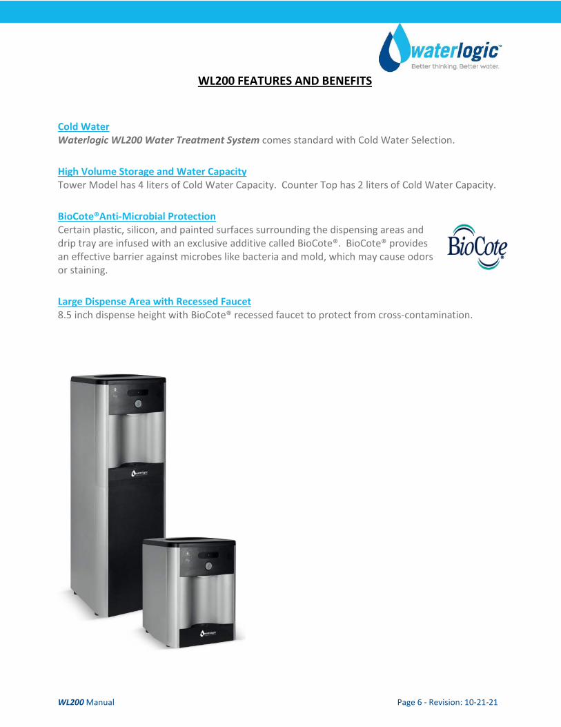
Cold Water Waterlogic WL200 Water Treatment System comes standard with Cold Water Selection.
High Volume Storage and Water Capacity Tower Model has 4 liters of Cold Water Capacity. Counter Top has 2 liters of Cold Water Capacity.
BioCote®Anti-Microbial Protection Certain plastic, silicon, and painted surfaces surrounding the dispensing areas and drip tray are infused with an exclusive additive called BioCote®. BioCote® provides an effective barrier against microbes like bacteria and mold, which may cause odors or staining.
Large Dispense Area with Recessed Faucet 8.5 inch dispense height with BioCote® recessed faucet to protect from cross-contamination.
WL200 Manual Page 7 - Revision: 10-21-21
WL200 CERTIFICATIONS
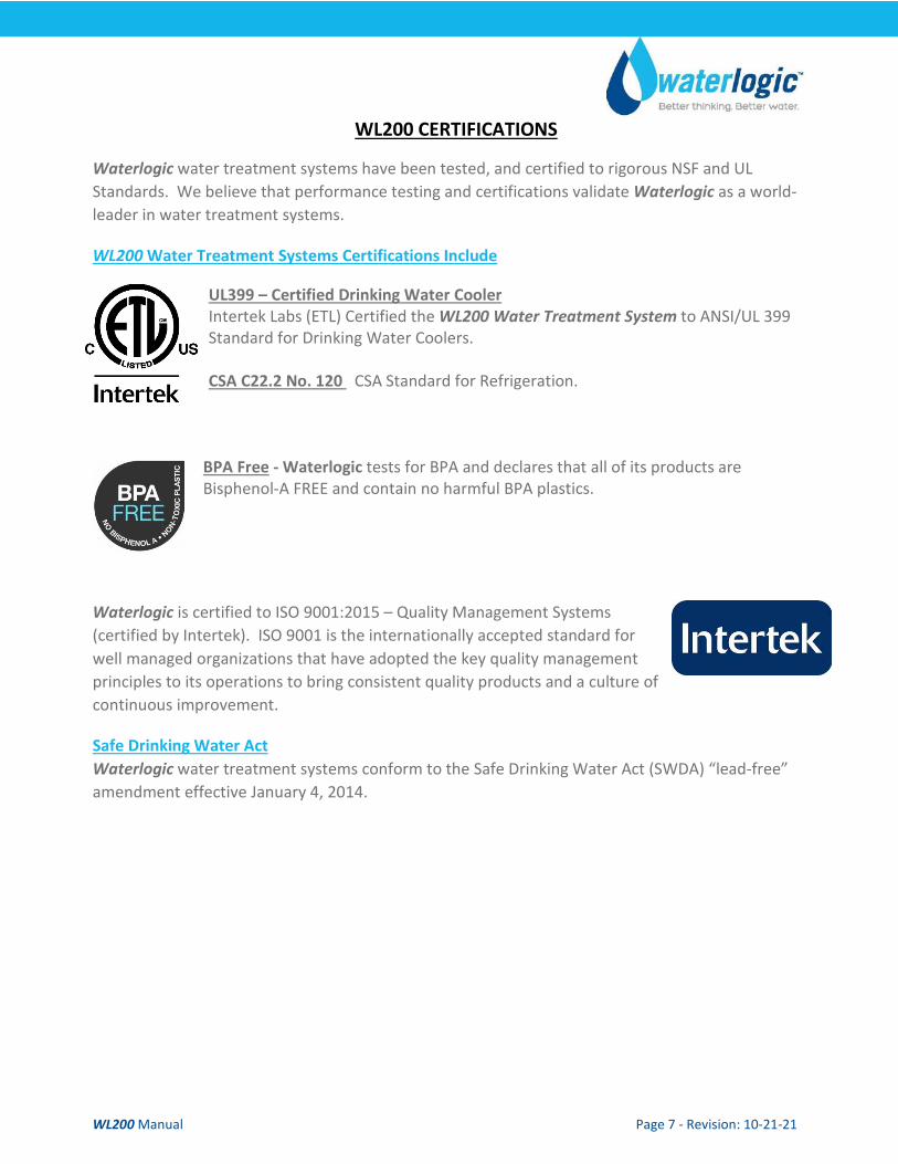
Waterlogic water treatment systems have been tested, and certified to rigorous NSF and UL Standards. We believe that performance testing and certifications validate Waterlogic as a world-leader in water treatment systems.
WL200 Water Treatment Systems Certifications Include
UL399 – Certified Drinking Water Cooler Intertek Labs (ETL) Certified the WL200 Water Treatment System to ANSI/UL 399 Standard for Drinking Water Coolers. CSA C22.2 No. 120 CSA Standard for Refrigeration.
BPA Free - Waterlogic tests for BPA and declares that all of its products are Bisphenol-A FREE and contain no harmful BPA plastics.
Waterlogic is certified to ISO 9001:2015 – Quality Management Systems (certified by Intertek). ISO 9001 is the internationally accepted standard for well managed organizations that have adopted the key quality management principles to its operations to bring consistent quality products and a culture of continuous improvement.
Safe Drinking Water Act Waterlogic water treatment systems conform to the Safe Drinking Water Act (SWDA) “lead-free” amendment effective January 4, 2014.
WL200 Manual Page 8 - Revision: 10-21-21
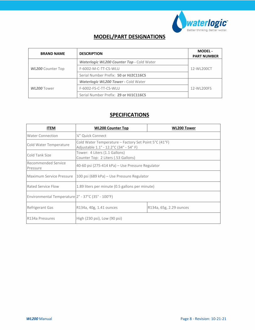
MODEL/PART DESIGNATIONS
BRAND NAME DESCRIPTION MODEL - PART NUMBER
WL200 Counter Top
Waterlogic WL200 Counter Top - Cold Water
12-WL200CT F-6002-M-C-TT-CS-WLU
Serial Number Prefix: 50 or HJ2C116CS
WL200 Tower
Waterlogic WL200 Tower - Cold Water
12-WL200FS F-6002-FS-C-TT-CS-WLU
Serial Number Prefix: 29 or HJ1C116CS
SPECIFICATIONS
ITEM WL200 Counter Top WL200 Tower
Water Connection ¼” Quick Connect
Cold Water Temperature Cold Water Temperature – Factory Set Point 5°C (41°F) Adjustable 1.1° - 12.2°C (34° - 54° F)
Cold Tank Size Tower: 4 Liters (1.1 Gallons) Counter Top: 2 Liters (.53 Gallons)
Recommended Service Pressure 40-60 psi (275-414 kPa) – Use Pressure Regulator
Maximum Service Pressure 100 psi (689 kPa) – Use Pressure Regulator
Rated Service Flow 1.89 liters per minute (0.5 gallons per minute)
Environmental Temperature 2° - 37°C (35° - 100°F)
Refrigerant Gas R134a, 40g, 1.41 ounces R134a, 65g, 2.29 ounces
R134a Pressures High (230 psi), Low (90 psi)
WL200 Manual Page 9 - Revision: 10-21-21
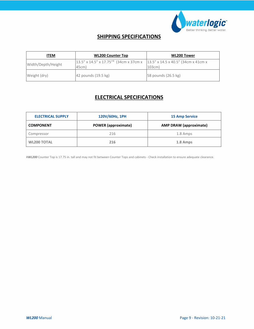
SHIPPING SPECIFICATIONS
ITEM WL200 Counter Top WL200 Tower
Width/Depth/Height 13.5” x 14.5” x 17.75”# (34cm x 37cm x 45cm)
13.5” x 14.5 x 40.5” (34cm x 41cm x 103cm)
Weight (dry) 42 pounds (19.5 kg) 58 pounds (26.5 kg)
ELECTRICAL SPECIFICATIONS
ELECTRICAL SUPPLY 120V/60Hz, 1PH 15 Amp Service
COMPONENT POWER (approximate) AMP DRAW (approximate)
Compressor 216 1.8 Amps
WL200 TOTAL 216 1.8 Amps
#WL200 Counter Top is 17.75 in. tall and may not fit between Counter Tops and cabinets - Check installation to ensure adequate clearance.
WL200 Manual Page 10 - Revision: 10-21-21
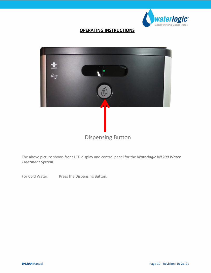
OPERATING INSTRUCTIONS
The above picture shows front LCD display and control panel for the Waterlogic WL200 Water Treatment System. For Cold Water: Press the Dispensing Button.
Dispensing Button
WL200 Manual Page 11 - Revision: 10-21-21
WATERLOGIC MANUFACTURED WATER TREATMENT SYSTEM LIMITED WARRANTY UNITED STATES AND CANADA ONLY
Waterlogic water treatment systems are guaranteed to the original purchaser to be free of defects in materials and workmanship for a period of three (3) years from the date of purchase, but in no event longer than forty-eight (48) months from the date of manufacture. Waterlogic Commercial Products, LLC (“Waterlogic”) based in the U.S.A. and its affiliated companies are not liable for any cost of removal, installation, transportation, or any other charges which may arise in connection with a warranty claim.
This warranty does not cover damage or wear to products caused by abnormal operating conditions, accident, abuse, misuse, unauthorized or improper alteration or repair, damage caused by or resulting from shipping or accident, damage caused by hot water, freezing, flood, fire, or acts of God. The effects from chlorine corrosion, scaling and normal wear are specifically excluded from this warranty. This warranty does not cover products used outside the countries where the unit was purchased, and does not cover products that were not installed in accordance with Waterlogic printed installation and operating instructions obtained in training or from www.waterlogic.us. Failure to follow all instructions for operation and maintenance voids the warranty. This warranty is not transferable.
To obtain warranty repairs or replacement, you must obtain a Return Authorization from Waterlogic. To obtain a Return Authorization, you must submit a Return Authorization form with supporting documentation to Waterlogic for evaluation. The form is available at www.waterlogic.us. Supporting documentation must include, but is not limited to; proof of purchase, installation date, failure date, and supporting installation and maintenance data. After you submit a Return Authorization form and supporting documentation, Waterlogic will determine whether a reasonably apparent defect in materials or workmanship covered by this limited warranty exists. If Waterlogic determines the claimed defect is covered by this warranty, Waterlogic will, at its sole discretion, determine whether to correct the defect or replace the unit, free of charge to you. If Waterlogic determines that the unit should be returned for warranty service, Waterlogic will approve of return in writing and will issue a Return Authorization which you must obtain prior to shipping the product. You are responsible for the cost of freight in to Waterlogic.
Waterlogic and its affiliated companies hereby limit the duration of any and all implied warranties to a maximum period of three (3) years from the date of purchase including, but not limited to, the implied warranties of merchantability and fitness for a particular purpose. Some states do not allow limitations on how long an implied warranty lasts, so the above limitation may not apply to you. Consequential and incidental damages are not recoverable under this warranty. Some states do not allow the exclusion or limitation of incidental or consequential damages, so the above limitation or exclusion may not apply to you.
This warranty gives you specific legal rights and you may also have other rights which may vary from state to state.
New Warranty Policy issued by Waterlogic Commercial Products LLC, USA - January 10, 2014 Waterlogic Commercials Products LLC Tel: (800) 288-1891 3175 Bass Pro Drive Website: waterlogic.us Grapevine, TX 76051
WL200 Manual Page 12 - Revision: 10-21-21
SERVICE REQUIREMENTS
WARNING! Read and understand the contents of this manual before attempting to service WL200 Water Purification System. Failure to follow the instructions in this manual could result in death, serious personal injury, or severe property damage. Only trained and qualified technicians should attempt to install, maintain, or service Waterlogic Equipment.
1. Visually inspect all electrical and water connections for signs of wear or damage. DANGER! HIGH VOLTAGE ELECTRICAL HAZARD. Unplug before inspection and service.
2. Ensure there is adequate (minimum of 2”) clearance around the unit and clean the condenser grill and compressor fan to provide efficient cooling system operation.
3. Sanitize the cold tank per instructions in the pre-installation procedures.
4. Clean and sanitize external surfaces of the unit. Use soap and water or chemicals that are compatible with ABS plastic and will not damage or degrade the product surfaces.
5. Empty and clean the drip tray on a regular basis.
6. Remove and clean the Faucet. Replace as needed. WARNING! SANITIZER MAY CONTAIN HAZARDOUS CHEMICALS. Use of proper personal protective equipment such as rubber gloves and eye protection is required.
WL200 Manual Page 13 - Revision: 10-21-21
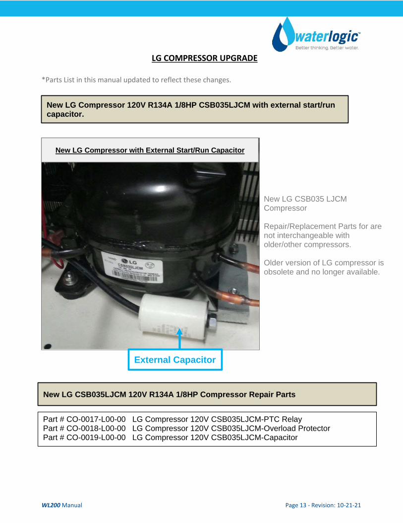
LG COMPRESSOR UPGRADE *Parts List in this manual updated to reflect these changes. New LG Compressor 120V R134A 1/8HP CSB035LJCM with external start/run
capacitor.
New LG Compressor with External Start/Run Capacitor
External Capacitor
New LG CSB035 LJCM Compressor Repair/Replacement Parts for are not interchangeable with older/other compressors. Older version of LG compressor is obsolete and no longer available.
Part # CO-0017-L00-00 LG Compressor 120V CSB035LJCM-PTC Relay Part # CO-0018-L00-00 LG Compressor 120V CSB035LJCM-Overload Protector Part # CO-0019-L00-00 LG Compressor 120V CSB035LJCM-Capacitor
New LG CSB035LJCM 120V R134A 1/8HP Compressor Repair Parts
WL200 Manual Page 14 - Revision: 10-21-21
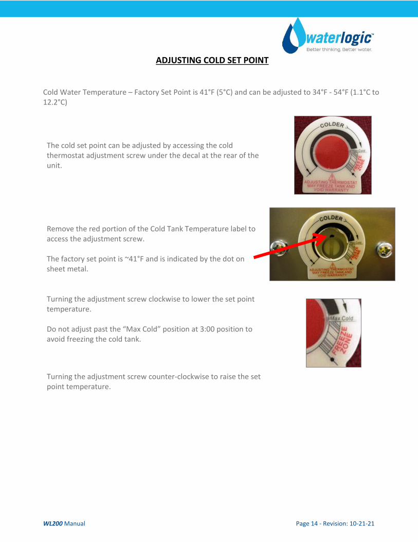
ADJUSTING COLD SET POINT
Cold Water Temperature – Factory Set Point is 41°F (5°C) and can be adjusted to 34°F - 54°F (1.1°C to 12.2°C)
The cold set point can be adjusted by accessing the cold thermostat adjustment screw under the decal at the rear of the unit.
Remove the red portion of the Cold Tank Temperature label to access the adjustment screw. The factory set point is ~41°F and is indicated by the dot on sheet metal.
Turning the adjustment screw clockwise to lower the set point temperature. Do not adjust past the “Max Cold” position at 3:00 position to avoid freezing the cold tank.
Turning the adjustment screw counter-clockwise to raise the set point temperature.
WL200 Manual Page 15 - Revision: 10-21-21
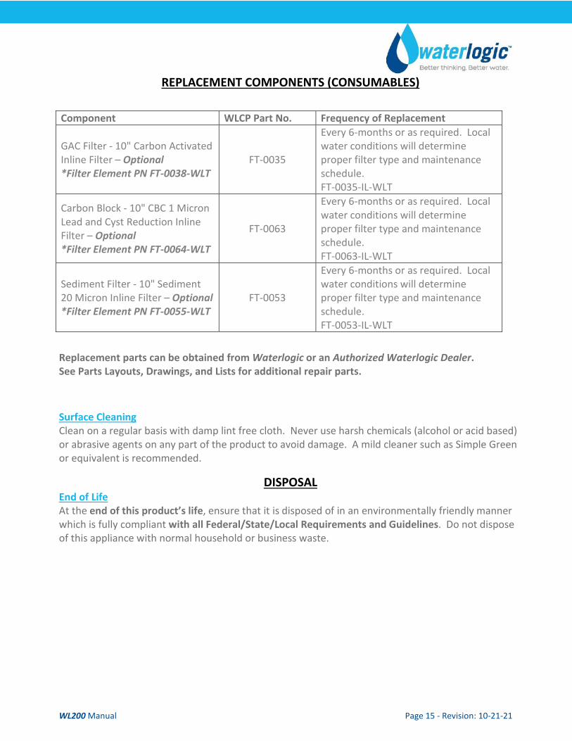
REPLACEMENT COMPONENTS (CONSUMABLES)
Component WLCP Part No. Frequency of Replacement
GAC Filter - 10" Carbon Activated Inline Filter – Optional *Filter Element PN FT-0038-WLT
FT-0035
Every 6-months or as required. Local water conditions will determine proper filter type and maintenance schedule. FT-0035-IL-WLT
Carbon Block - 10" CBC 1 Micron Lead and Cyst Reduction Inline Filter – Optional *Filter Element PN FT-0064-WLT
FT-0063
Every 6-months or as required. Local water conditions will determine proper filter type and maintenance schedule. FT-0063-IL-WLT
Sediment Filter - 10" Sediment 20 Micron Inline Filter – Optional *Filter Element PN FT-0055-WLT
FT-0053
Every 6-months or as required. Local water conditions will determine proper filter type and maintenance schedule. FT-0053-IL-WLT
Replacement parts can be obtained from Waterlogic or an Authorized Waterlogic Dealer. See Parts Layouts, Drawings, and Lists for additional repair parts.
Surface Cleaning Clean on a regular basis with damp lint free cloth. Never use harsh chemicals (alcohol or acid based) or abrasive agents on any part of the product to avoid damage. A mild cleaner such as Simple Green or equivalent is recommended.
DISPOSAL End of Life At the end of this product’s life, ensure that it is disposed of in an environmentally friendly manner which is fully compliant with all Federal/State/Local Requirements and Guidelines. Do not dispose of this appliance with normal household or business waste.
WL200 Manual Page 16 - Revision: 10-21-21
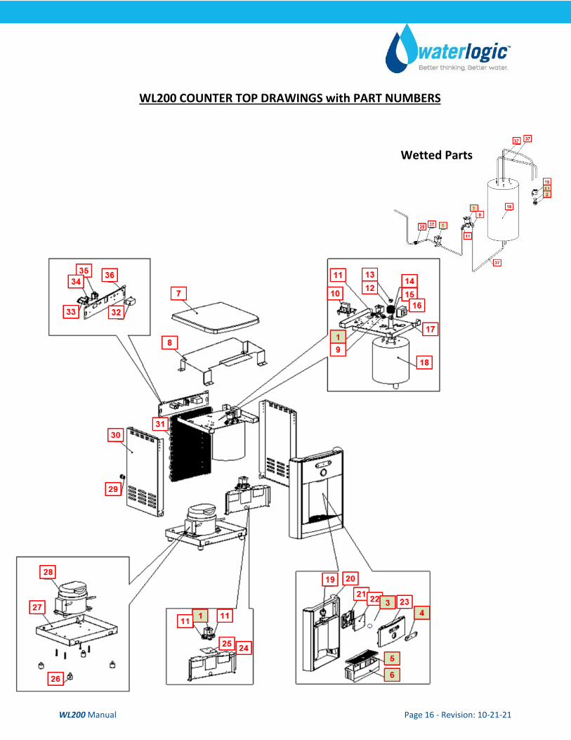
WL200 COUNTER TOP DRAWINGS with PART NUMBERS
Wetted Parts

WL200 Manual Page 17 - Revision: 10-21-21
No WLCP Part No. Description Part No Stocked?
Consumables
Optional FT-0035 GAC Filter - 10" Carbon Activated Inline Filter - Optional Filter Element PN FT-0038-WLT
FT-0035-IL-WLT Yes
Optional FT-0063
Carbon Block - 10" CBC 1-Micron Lead and Cyst Reduction Inline Filter - Optional Filter Element PN FT-0064-WLT
FT-0063-IL-WLT Yes
Optional FT-0053
Sediment Filter - 10" Sediment 20 Micron Inline Filter Optional Filter Element PN FT-0055-WLT
FT-0053-IL-WLT Yes
Recommended Spare Parts
1 12-1500 Solenoid Valve 500 mm Recommend stocking 2 each per every 10 units purchased
PU-4016 Yes
1.1 CU-0001 Solenoid Cushion Recommend stocking 2 each per every 10 units purchased
CU-0001 Yes
2 10-3048
Faucet Nipple – Blue with Screen Recommend stocking 2 each per every 10 units purchased
PL-1013 Yes
3 12-8600
Silicon Button Key Mat Cold Only Recommend stocking 5 each per every 10 units purchased
PL-1100 Yes
4 12-8610 Button Label - Cold Only Recommend stocking 2 each per every 10 units purchased
LP-7085 Yes
5 12-8150 Drip Tray Grill – Charcoal Recommend stocking 4 each per every 10 units purchased
PL-1152 Yes
6 12-8055
Drip Tray - Charcoal with Waterlogic Logo Recommend stocking 4 each per every 10 units purchased
PL-1156 Yes
Not Shown 01-2076
ScaleKleen Recommend stocking 2 each per every 10 units purchased
NA Yes

WL200 Manual Page 18 - Revision: 10-21-21
Remaining of Parts
7 12-8060 Flat Top Cover - Charcoal with Texture Counter Top Only
PL-1249-CN Yes
8 ST-0049-L00-00
High Voltage Metal Cover (ETL-Certification) Counter Top Only
ST-0049-L00-00 Yes
9 Purchase from John
Guest
5/16” x ¼” Reducing Elbow John Guest P/N PI211008S PU-4007 No
10 NA Leak Detection PCB EN-6111-A No
10.1 10-3017 PCB Stand-off Pin EN-6059 Yes
11 Purchase from John
Guest
1/4” Union Elbow John Guest P/N P10308S PU-4008 No
12 12-1210 UV Lamp Retaining Threaded Nut Counter Top Only
PL-1128 Yes
13 10-8085 UV Lamp Fixing Rubber (Silicon) Counter Top Only CT-2001-B Yes
14 NA Quartz Sleeve (100mm) Counter Top Only CT-2062-CN No
15 10-2500 Black O-Ring for Quartz Sleeve Counter Top Only CT-2006 Yes
16 12-3117 Power Transformer 120V EL-5003-A Yes
17 12-3165 Upper Shelf Counter Top Only ST-8150-B Yes
WL200 Manual Page 19 - Revision: 10-21-21
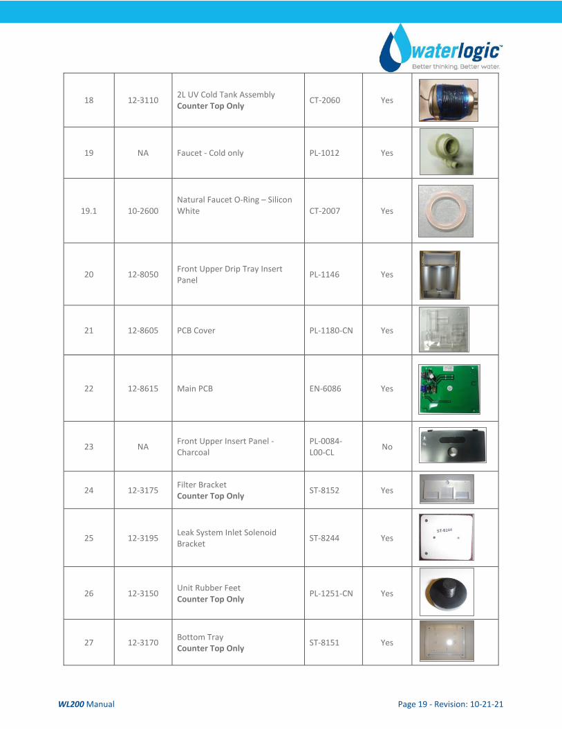
18 12-3110 2L UV Cold Tank Assembly Counter Top Only CT-2060 Yes
19 NA Faucet - Cold only PL-1012 Yes
19.1 10-2600 Natural Faucet O-Ring – Silicon White
CT-2007 Yes
20 12-8050 Front Upper Drip Tray Insert Panel PL-1146 Yes
21 12-8605 PCB Cover PL-1180-CN Yes
22 12-8615 Main PCB EN-6086 Yes
23 NA Front Upper Insert Panel - Charcoal
PL-0084-L00-CL No
24 12-3175 Filter Bracket Counter Top Only ST-8152 Yes
25 12-3195 Leak System Inlet Solenoid Bracket ST-8244 Yes
26 12-3150 Unit Rubber Feet Counter Top Only PL-1251-CN Yes
27 12-3170 Bottom Tray Counter Top Only ST-8151 Yes
WL200 Manual Page 20 - Revision: 10-21-21
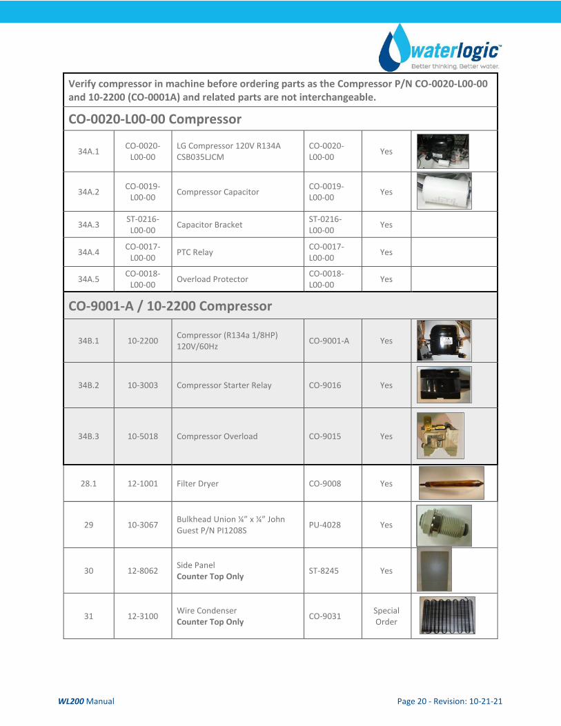
Verify compressor in machine before ordering parts as the Compressor P/N CO-0020-L00-00 and 10-2200 (CO-0001A) and related parts are not interchangeable.
CO-0020-L00-00 Compressor
34A.1 CO-0020-L00-00
LG Compressor 120V R134A CSB035LJCM
CO-0020-L00-00 Yes
34A.2 CO-0019-L00-00 Compressor Capacitor CO-0019-
L00-00 Yes
34A.3 ST-0216-L00-00 Capacitor Bracket ST-0216-
L00-00 Yes
34A.4 CO-0017-L00-00 PTC Relay CO-0017-
L00-00 Yes
34A.5 CO-0018-L00-00 Overload Protector CO-0018-
L00-00 Yes
CO-9001-A / 10-2200 Compressor
34B.1 10-2200 Compressor (R134a 1/8HP) 120V/60Hz CO-9001-A Yes
34B.2 10-3003 Compressor Starter Relay CO-9016 Yes
34B.3 10-5018 Compressor Overload CO-9015 Yes
28.1 12-1001 Filter Dryer CO-9008 Yes
29 10-3067 Bulkhead Union ¼” x ¼” John Guest P/N PI1208S PU-4028 Yes
30 12-8062 Side Panel Counter Top Only ST-8245 Yes
31 12-3100 Wire Condenser Counter Top Only CO-9031 Special
Order
WL200 Manual Page 21 - Revision: 10-21-21
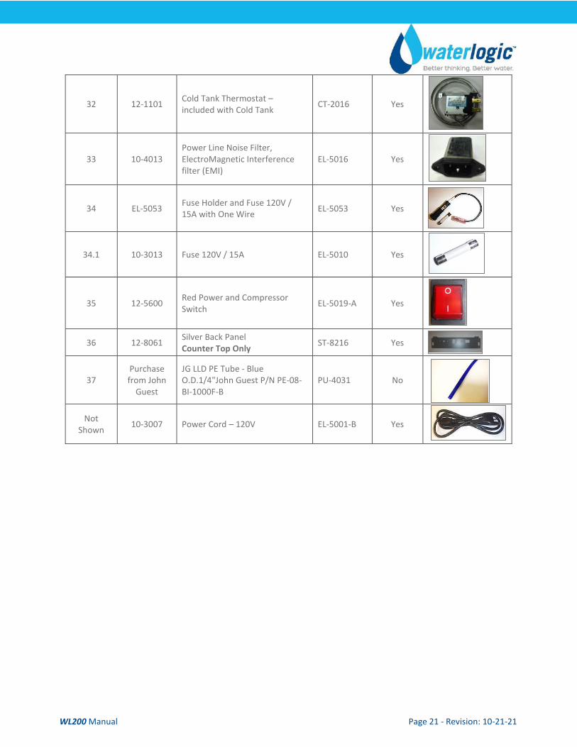
32 12-1101 Cold Tank Thermostat – included with Cold Tank CT-2016 Yes
33 10-4013 Power Line Noise Filter, ElectroMagnetic Interference filter (EMI)
EL-5016 Yes
34 EL-5053 Fuse Holder and Fuse 120V / 15A with One Wire EL-5053 Yes
34.1 10-3013 Fuse 120V / 15A EL-5010 Yes
35 12-5600 Red Power and Compressor Switch EL-5019-A Yes
36 12-8061 Silver Back Panel Counter Top Only ST-8216 Yes
37 Purchase from John
Guest
JG LLD PE Tube - Blue O.D.1/4"John Guest P/N PE-08-BI-1000F-B
PU-4031 No
Not Shown 10-3007 Power Cord – 120V EL-5001-B Yes
WL200 Manual Page 22 - Revision: 10-21-21
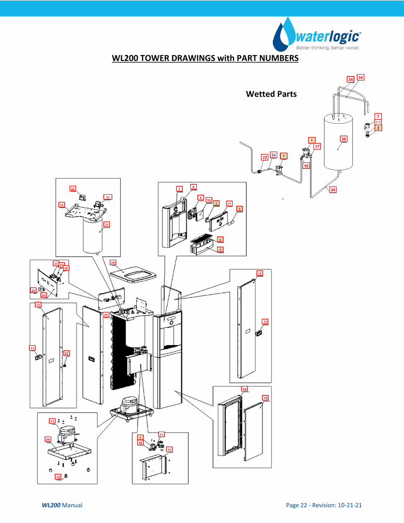
WL200 TOWER DRAWINGS with PART NUMBERS
Wetted Parts
WL200 Manual Page 23 - Revision: 10-21-21
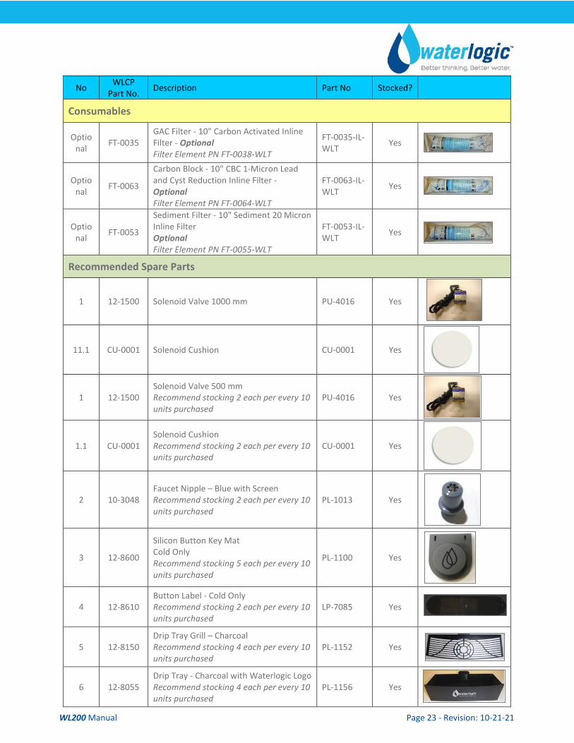
No WLCP Part No. Description Part No Stocked?
Consumables
Optional FT-0035
GAC Filter - 10" Carbon Activated Inline Filter - Optional Filter Element PN FT-0038-WLT
FT-0035-IL-WLT Yes
Optional FT-0063
Carbon Block - 10" CBC 1-Micron Lead and Cyst Reduction Inline Filter - Optional Filter Element PN FT-0064-WLT
FT-0063-IL-WLT Yes
Optional FT-0053
Sediment Filter - 10" Sediment 20 Micron Inline Filter Optional Filter Element PN FT-0055-WLT
FT-0053-IL-WLT Yes
Recommended Spare Parts
1 12-1500 Solenoid Valve 1000 mm PU-4016 Yes
11.1 CU-0001 Solenoid Cushion CU-0001 Yes
1 12-1500 Solenoid Valve 500 mm Recommend stocking 2 each per every 10 units purchased
PU-4016 Yes
1.1 CU-0001 Solenoid Cushion Recommend stocking 2 each per every 10 units purchased
CU-0001 Yes
2 10-3048 Faucet Nipple – Blue with Screen Recommend stocking 2 each per every 10 units purchased
PL-1013 Yes
3 12-8600
Silicon Button Key Mat Cold Only Recommend stocking 5 each per every 10 units purchased
PL-1100 Yes
4 12-8610 Button Label - Cold Only Recommend stocking 2 each per every 10 units purchased
LP-7085 Yes
5 12-8150 Drip Tray Grill – Charcoal Recommend stocking 4 each per every 10 units purchased
PL-1152 Yes
6 12-8055 Drip Tray - Charcoal with Waterlogic Logo Recommend stocking 4 each per every 10 units purchased
PL-1156 Yes
WL200 Manual Page 24 - Revision: 10-21-21
Not Shown 01-2076
ScaleKleen Recommend stocking 2 each per every 10 units purchased
NA Yes
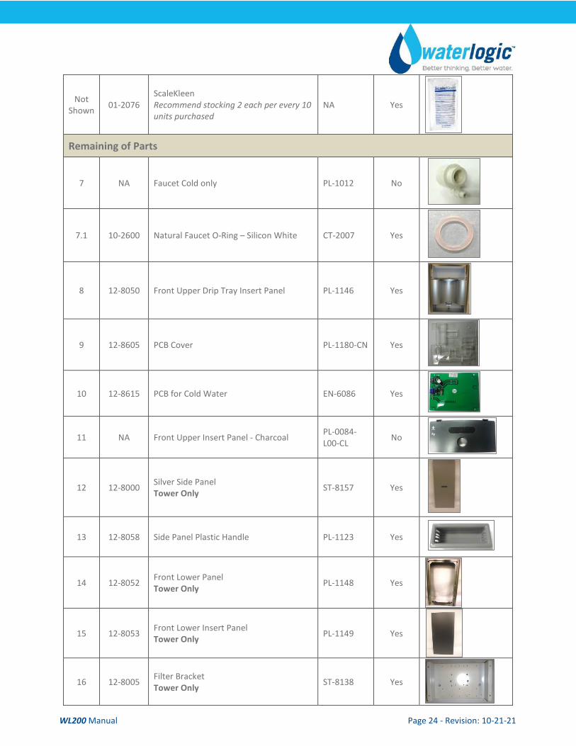
Remaining of Parts
7 NA Faucet Cold only PL-1012 No
7.1 10-2600 Natural Faucet O-Ring – Silicon White CT-2007 Yes
8 12-8050 Front Upper Drip Tray Insert Panel PL-1146 Yes
9 12-8605 PCB Cover PL-1180-CN Yes
10 12-8615 PCB for Cold Water EN-6086 Yes
11 NA Front Upper Insert Panel - Charcoal PL-0084-L00-CL No
12 12-8000 Silver Side Panel Tower Only ST-8157 Yes
13 12-8058 Side Panel Plastic Handle PL-1123 Yes
14 12-8052 Front Lower Panel Tower Only PL-1148 Yes
15 12-8053 Front Lower Insert Panel Tower Only PL-1149 Yes
16 12-8005 Filter Bracket Tower Only ST-8138 Yes
WL200 Manual Page 25 - Revision: 10-21-21
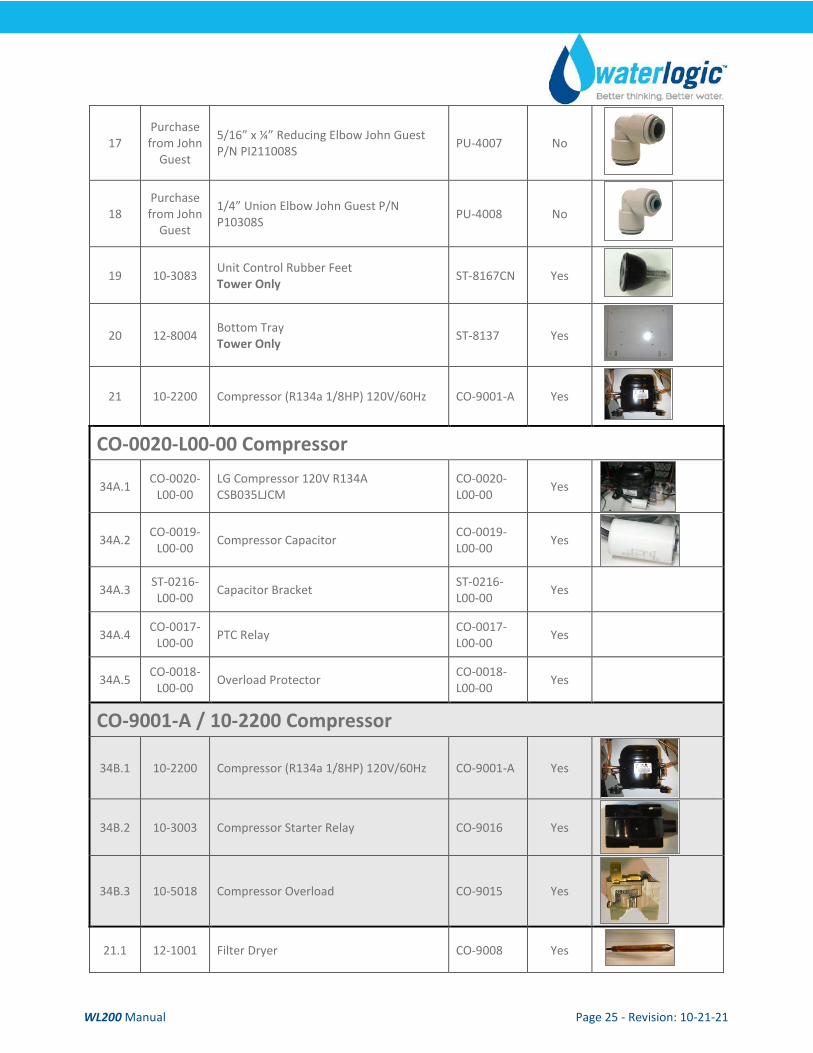
17 Purchase from John
Guest
5/16” x ¼” Reducing Elbow John Guest P/N PI211008S PU-4007 No
18 Purchase from John
Guest
1/4” Union Elbow John Guest P/N P10308S PU-4008 No
19 10-3083 Unit Control Rubber Feet Tower Only ST-8167CN Yes
20 12-8004 Bottom Tray Tower Only ST-8137 Yes
21 10-2200 Compressor (R134a 1/8HP) 120V/60Hz CO-9001-A Yes
CO-0020-L00-00 Compressor
34A.1 CO-0020-L00-00
LG Compressor 120V R134A CSB035LJCM
CO-0020-L00-00 Yes
34A.2 CO-0019-L00-00 Compressor Capacitor CO-0019-
L00-00 Yes
34A.3 ST-0216-L00-00 Capacitor Bracket ST-0216-
L00-00 Yes
34A.4 CO-0017-L00-00 PTC Relay CO-0017-
L00-00 Yes
34A.5 CO-0018-L00-00 Overload Protector CO-0018-
L00-00 Yes
CO-9001-A / 10-2200 Compressor
34B.1 10-2200 Compressor (R134a 1/8HP) 120V/60Hz CO-9001-A Yes
34B.2 10-3003 Compressor Starter Relay CO-9016 Yes
34B.3 10-5018 Compressor Overload CO-9015 Yes
21.1 12-1001 Filter Dryer CO-9008 Yes
WL200 Manual Page 26 - Revision: 10-21-21
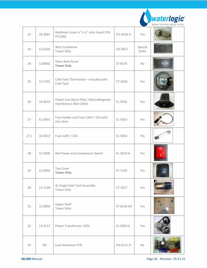
22 10-3067 Bulkhead Union ¼” x ¼” John Guest P/N PI1208S PU-4028-A Yes
23 12-8102 Wire Condenser Tower Only CO-9027 Special
Order
24 12-8002 Silver Back Panel Tower Only ST-8135 No
25 12-1101 Cold Tank Thermostat – included with Cold Tank CT-2016 Yes
26 10-4013 Power Line Noise Filter, ElectroMagnetic Interference filter (EMI) EL-5016 Yes
27 EL-5053 Fuse Holder and Fuse 120V / 15A with One Wire EL-5053 Yes
27.1 10-3013 Fuse 120V / 15A EL-5010 Yes
28 12-5600 Red Power and Compressor Switch EL-5019-A Yes
29 12-8054 Top Cover Tower Only PL-1150 Yes
30 12-1100 4L Single Cold Tank Assembly Tower Only CT-2017 Yes
31 12-8003 Upper Shelf Tower Only ST-8136-R2 Yes
32 12-3117 Power Transformer 120V EL-5003-A Yes
33 NA Leak Detection PCB EN-6111-A No
WL200 Manual Page 27 - Revision: 10-21-21
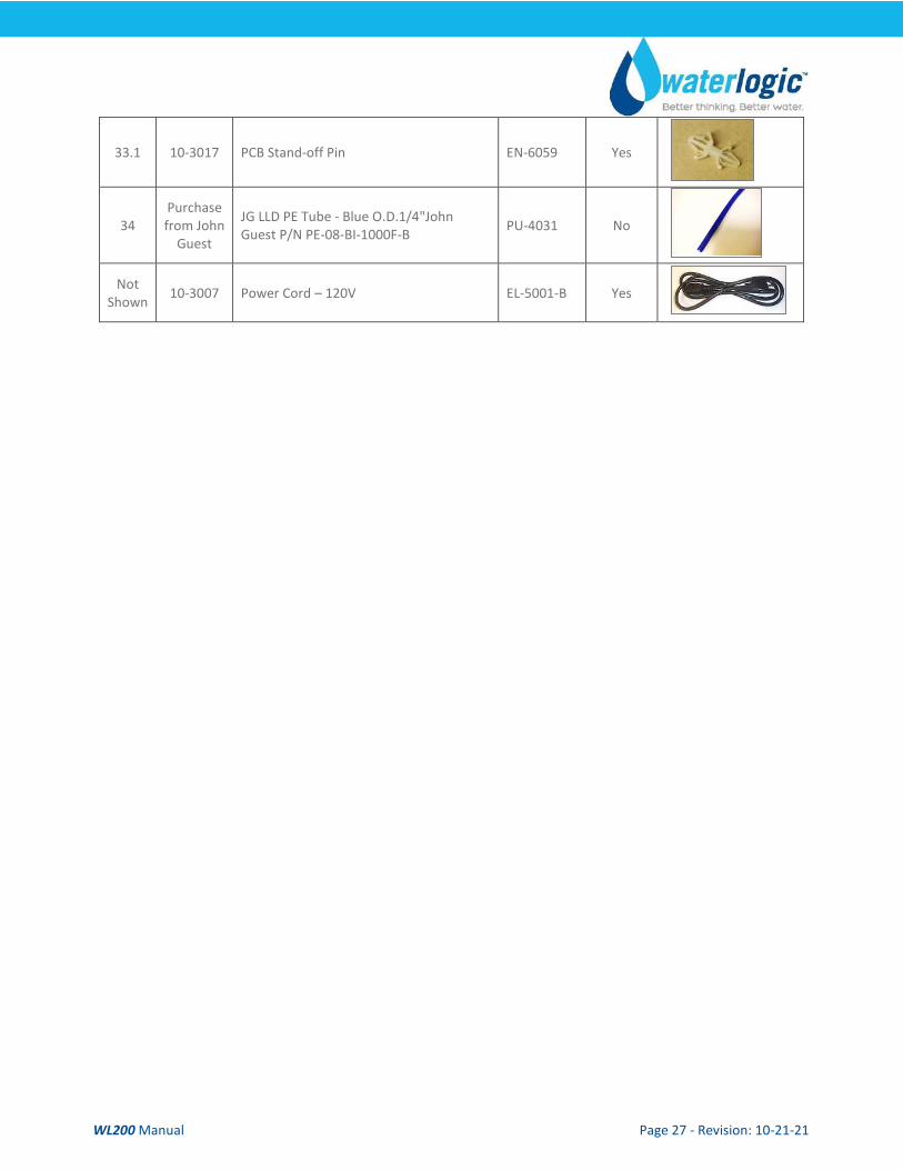
33.1 10-3017 PCB Stand-off Pin EN-6059 Yes
34 Purchase from John
Guest
JG LLD PE Tube - Blue O.D.1/4"John Guest P/N PE-08-BI-1000F-B PU-4031 No
Not Shown 10-3007 Power Cord – 120V EL-5001-B Yes
WL200 Manual Page 28 - Revision: 10-21-21
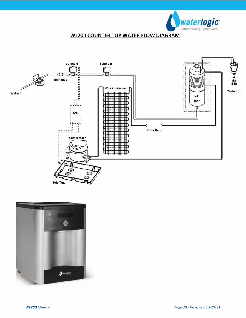
WL200 COUNTER TOP WATER FLOW DIAGRAM
WL200 Manual Page 29 - Revision: 10-21-21
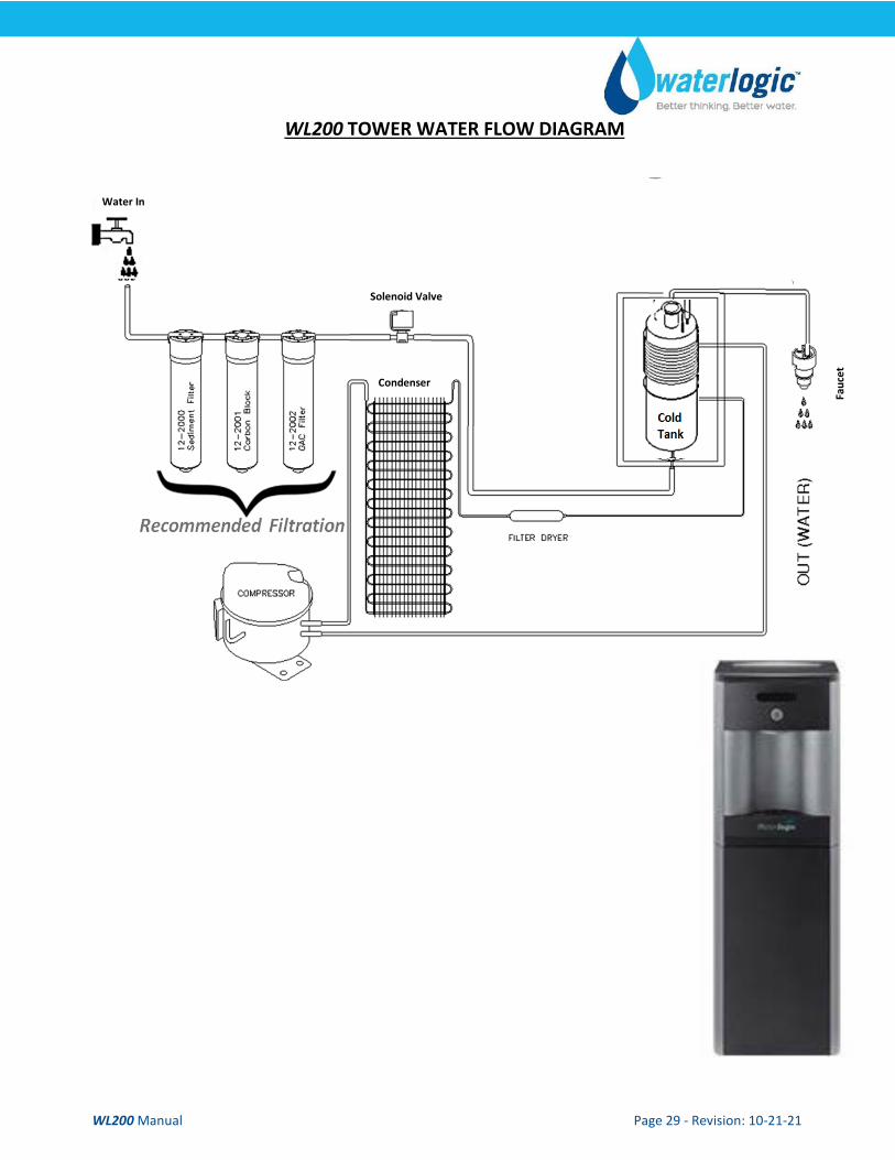
WL200 TOWER WATER FLOW DIAGRAM
Water In
Solenoid Valve
Condenser
Fa
ucet
WL200 Manual Page 30 - Revision: 10-21-21
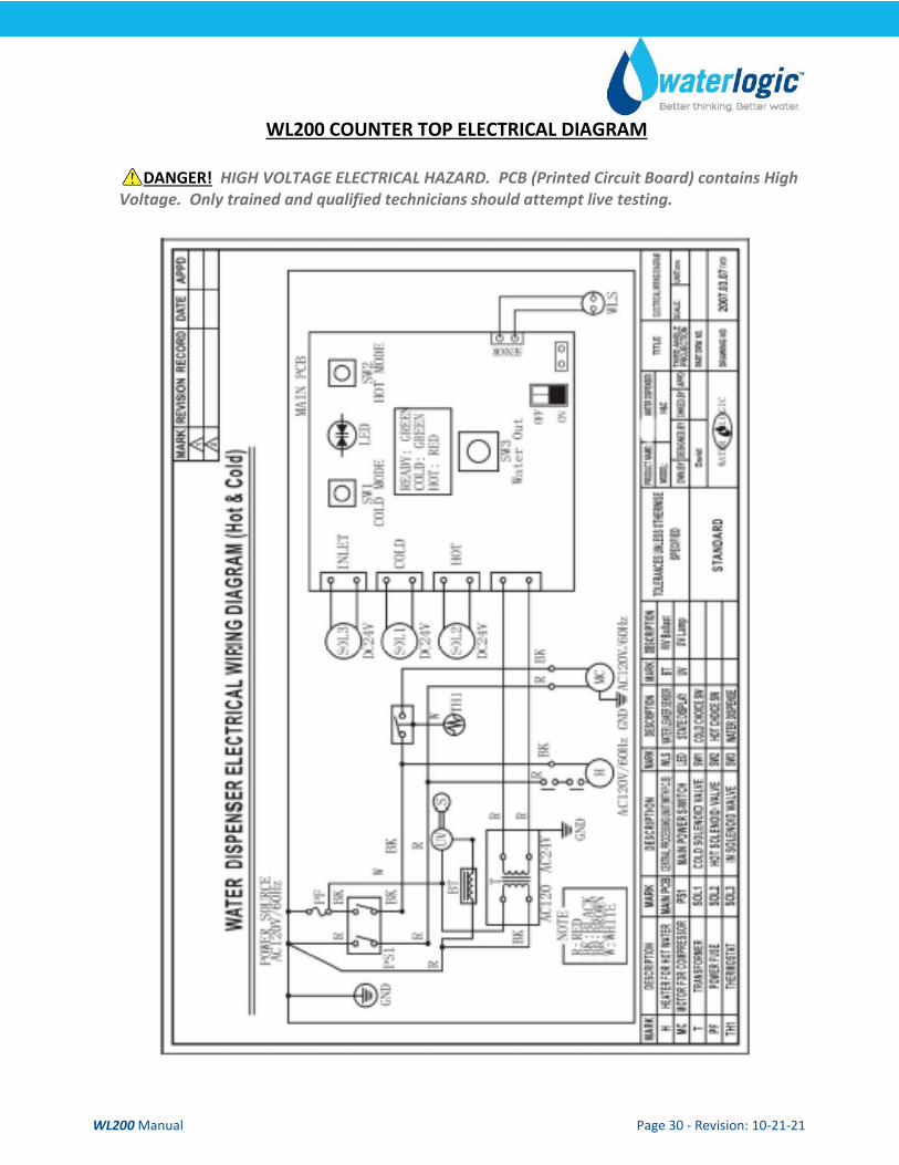
WL200 COUNTER TOP ELECTRICAL DIAGRAM
DANGER! HIGH VOLTAGE ELECTRICAL HAZARD. PCB (Printed Circuit Board) contains High Voltage. Only trained and qualified technicians should attempt live testing.
WL200 Manual Page 31 - Revision: 10-21-21
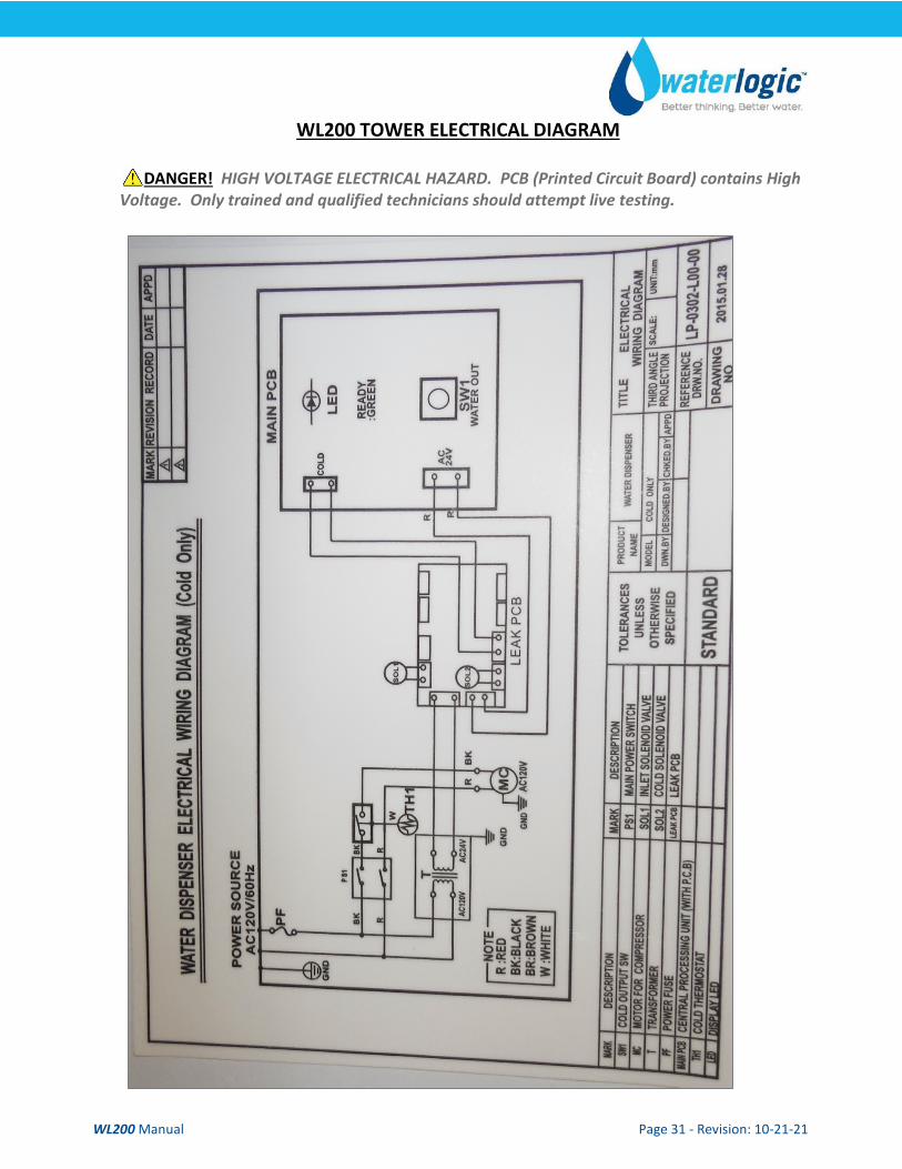
WL200 TOWER ELECTRICAL DIAGRAM
DANGER! HIGH VOLTAGE ELECTRICAL HAZARD. PCB (Printed Circuit Board) contains High Voltage. Only trained and qualified technicians should attempt live testing.
WL200 Manual Page 32 - Revision: 10-21-21
PRE-INSTALLATION PROCEDURES
DANGER! ELECTRICAL SHOCK HAZARD. Only qualified personnel who have read and understand this entire manual should attempt to install, or service this unit, failure to do so could result in death or serious injury. DO NOT plug into an electrical supply until specifically instructed.
WARNING! ALWAYS SANITIZE BEFORE USE.
Sanitize before use to eliminate any potential microbiological contaminates. CAUTION! DRIP TRAY DRAIN. If you intend to provide a drip tray drain for your customer, be aware that you will be called multiple times per month to service and unclog the tubing leading away from the drip tray to drain. Users will clog the drain with paper clips, erasers, napkins, tea bags, gum, and various other intended items. Waterlogic recommends you establish a minimum of weekly visits to the machine for cleaning of the drip tray drain.
Materials Needed: • Personal Protective Equipment. Rubber or Nitrile Safety Gloves and Protective Eyewear • Phillips Screwdriver • Temperature Gage • Water Pitcher or Container to collect water from the faucet • 5 gallon container or drain basin • Sanitizer - Household Bleach (5.25% Sodium Hypochlorite) or Citric Acid Based Cleaner • ¼” Plastic Tubing, at least 4 feet in length, and assorted ¼” quick connect fittings • TDS Meter and Test Strips for measuring chlorine - Optional
1. Unpack the Waterlogic WL200 Water Treatment System and check exterior for damage. Sanitizing
Sanitize using a Household Bleach (5.25% Sodium Hypochlorite solution) or other approved cleaner throughout the cold and sparkling water circuits. Follow all instructions on the sanitizer and flush with fresh water through the faucet until odor and taste is acceptable.
WARNING! USE PROPER PERSONAL PROTECTIVE EQUIPMENT Always ensure proper ventilation and use proper personal protective equipment such as gloves and eye protection when using chemicals. Refer to Material Safety Data Sheet for specific requirements of each chemical product. Take all necessary precautions to prevent sanitizer from contacting eyes, clothing, and any other surfaces in could damage (carpets).
2. Put 1 teaspoon of sanitizer per directions or use Bleach Solution (1 teaspoon = 1/6 oz. = 5 ml = ½ cap full) of household bleach (Sodium Hypochlorite 5 - 10% Concentration) in the Sanitizing Cartridge. Always ensure sanitizer is compatible with stainless steel and acetyl plastic.
WL200 Manual Page 33 - Revision: 10-21-21
3. Connect sanitizing cartridge to inlet water supply and connect to inlet bulkhead fitting on back of unit. Turn on water supply.
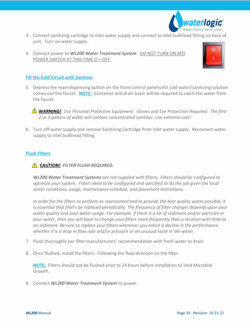
4. Connect power to WL200 Water Treatment System. DO NOT TURN ON RED
POWER SWITCH AT THIS TIME O = OFF.
Fill the Cold Circuit with Sanitizer
5. Depress the main dispensing button on the front control panel until cold water/sanitizing solution comes out the faucet. NOTE: Container and drain basin will be required to catch the water from the faucet.
WARNING! Use Personal Protective Equipment. Gloves and Eye Protection Required. The first 2 or 3 gallons of water will contain concentrated sanitizer. Use extreme care!
6. Turn off water supply and remove Sanitizing Cartridge from inlet water supply. Reconnect water
supply to inlet bulkhead fitting.
Flush Filters
CAUTION! FILTER FLUSH REQUIRED. WL200 Water Treatment Systems are not supplied with filters. Filters should be configured to optimize your system. Filters need to be configured and specified to do the job given the local water conditions, usage, maintenance schedule, and placement restrictions. In order for the filters to perform as represented and to provide the best quality water possible, it is essential that filters be replaced periodically. The frequency of filter changes depends upon your water quality and your water usage. For example, if there is a lot of sediment and/or particles in your water, then you will have to change your filters more frequently than a location with little to no sediment. Be sure to replace your filters whenever you notice a decline in the performance, whether it is a drop in flow rate and/or pressure or an unusual taste in the water.
7. Flush thoroughly per filter manufacturers’ recommendation with fresh water to drain.
8. Once flushed, install the filters. Following the flow direction on the filter.
NOTE: Filters should not be flushed prior to 24 hours before installation to limit Microbial Growth.
9. Connect WL200 Water Treatment System to power.

WL200 Manual Page 34 - Revision: 10-21-21
Flushing the Sanitizer from the Machine 10. Place a pitcher, catch basin, or other container under the faucet of the WL200 Water Treatment
System.
11. Flush the Cold Tank. Run several gallons of water through the faucet by dispensing cold water to dilute and remove the sanitizer from the cold circuit. You can use chlorine test strips to evaluate the water.
12. Once the sanitizer odor/taste has been flushed out of the cold side of the machine the
sanitization process for the Cold Circuit is now complete.

WL200 Manual Page 35 - Revision: 10-21-21
WL200 COUNTER TOP DRAINING INSTRUCTIONS
Drain the WL200 Water Treatment System for transportation. WARNING! STORE UNIT EMPTY. ALWAYS SANITIZE BEFORE REUSE.
The unit must be completely drained and sealed before storing to avoid stagnation and reduce microbial growth).
Turn off Water Supply and Bleed Water Pressure 1. Isolate the WL200 Water Treatment System from feed
water by turning off the supply.
2. Dispense cold still water to relieve any pressure built up in the system.
3. Remove the water supply line from the inlet line bulkhead
fitting at back of the WL200 Water Treatment System.
4. Depress Cold Water Dispense Button until all Cold Water has drained from the WL200 Water Treatment System.
5. Depress Hot Water Dispense Button until all Hot Water has drained from the WL200 Water Treatment Machine.
Water Supply Line
WL200 Manual Page 36 - Revision: 10-21-21
WL200 TOWER DRAINING INSTRUCTIONS
Draining Notes
Drain the WL200 Water Treatment System for transportation.
WARNING! STORE AND TRANSPORT UNIT EMPTY. ALWAYS SANITIZE BEFORE USE. The unit must be completely drained before storing to avoid stagnation and reduce microbiological contamination (potential bacterial growth). Always sanitize before use to eliminate any potential microbiological contaminates.
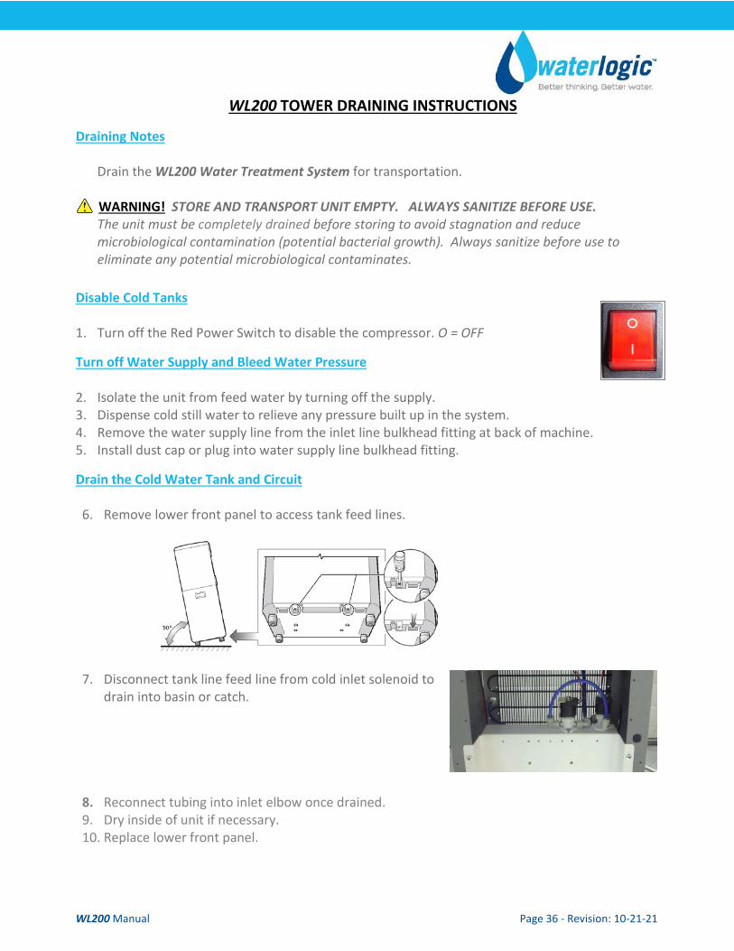
Disable Cold Tanks 1. Turn off the Red Power Switch to disable the compressor. O = OFF
Turn off Water Supply and Bleed Water Pressure 2. Isolate the unit from feed water by turning off the supply. 3. Dispense cold still water to relieve any pressure built up in the system. 4. Remove the water supply line from the inlet line bulkhead fitting at back of machine. 5. Install dust cap or plug into water supply line bulkhead fitting.
Drain the Cold Water Tank and Circuit 6. Remove lower front panel to access tank feed lines.
7. Disconnect tank line feed line from cold inlet solenoid to
drain into basin or catch.
8. Reconnect tubing into inlet elbow once drained. 9. Dry inside of unit if necessary. 10. Replace lower front panel.
WL200 Manual Page 37 - Revision: 10-21-21
INSTALLATION PROCEDURES
Safety and Installation Guidelines Ensure all Local, State, and Federal Laws and Codes including health and safety guidelines are met when installing Waterlogic Equipment. Only qualified service technicians should attempt installation and service of Waterlogic Equipment.
WARNING! ELECTRICAL SHOCK HAZARD. Always unplug (isolate from power supply) to prevent electrical shock except where electrical tests are specified.
WARNING! IMPROPER SUPPLY OR CONNECTION CAN RESULT IS RISK OF SHOCK. Connect to a 15-amp 120V 60Hz properly grounded outlet (GFI is recommended). Ensure polarity is correct and always use a 3-prong outlet. Consult a qualified electrician if you have any questions.
WARNING! USE ONLY Waterlogic SUPPLIED POWER CORD. Locate system within 5 feet of power supply. Never use an extension cord or adapter. Do not use a damaged power cord or plug. Keep power cord out of heavy traffic areas and away from heat sources. Do not, under any circumstances, remove ground prong or alter the power cord. Never pull the power plug from the outlet with a wet hand or allow the plug to get wet. Failure to use the supplied power cord will void UL Certification and Warranty.
CAUTION! INDOOR USE ONLY. Never expose to direct sunlight, heat sources, or ambient air temperature above 37°C (100°F) or below 2°C (35°F). Install indoors and keep unit away from excessive humidity. Never expose to freezing temperatures. Ensure there is adequate clearance around the unit to allow refrigeration system condenser to dissipate heat. Warmer environments require more clearance around the unit. Minimum clearance around all surfaces of the machine is 2-inches. Installs where the ambient temperature exceeds 26.7°C (80°F), require a minimum of 4-inches clearance for proper heat dissipation and efficient operation.
CAUTION! USE A WATER PRESSURE REGULATOR. Waterlogic will not be responsible for injury or damage caused by excessive water pressure. Operating pressure must be 40 psi to 60 psi. Be aware any of potential pressure surges caused by building/municipal pumping stations.
CAUTION! USE UV STABILIZED SUPPLY LINES. Feed the unit with a potable ambient or cold water supply only. Feed water over 37°C (100°F) can damage the treatment components. Water block devices and external leak detectors are strongly recommended. Locate the unit as close to the water supply and the electrical connections as possible.
WARNING! STORE AND TRANSPORT UNIT EMPTY. ALWAYS SANITIZE BEFORE USE. The unit must be completely drained and sealed before storing to avoid stagnation and reduce microbiological contamination (potential bacterial growth). Sanitize before use to eliminate any potential microbiological contaminates
Pre-installation and sanitization procedures as prescribed in this manual must be performed before installing the WL200 Water Treatment System. Always install indoors and place the Waterlogic WL200 Water Treatment System on a firm, flat and stable surface.
WL200 Manual Page 38 - Revision: 10-21-21
1. Attach the water supply line to the 1/4” feed water inlet bulkhead fitting on the back of the unit.
Waterlogic requires the use of a water pressure regulator. Water feed pressure must be between 40-60 psi. Turn on the water supply and check for leaks.
2. Check to ensure that the Red Power Switch is off. O=OFF
3. Connect the power cord to the back of the Waterlogic WL200 Water Treatment System and to a 120 Volt supply.
4. Fill the Cold Tank. Hold a container under the dispensing faucet, press and hold the main dispensing button until a continuous flow of water is obtained. Once a continuous flow is obtained, release the dispensing button. Cold tank is now full.
5. Move the Waterlogic WL200 Water Treatment System into its final operating position. Be sure that a minimum of 2” clearance is maintained around both the sides and the back of the unit. This is important to allow proper airflow and heat exchange of refrigeration system.
6. Level unit using the adjustable feet to level if necessary. Never install on incline.
7. Turn the Red Power Switch on. I=ON.
8. When the unit has reached its Cold Temp Set Point Temperature, the compressor will cycle off.
9. Once the unit is at the target temperature(s), sample the water to ensure water meets expectations and additional rinsing or adjustment is not required.
10. Check the unit for any leaks. External Leak Protection is always recommended.
WL200 Manual Page 39 - Revision: 10-21-21
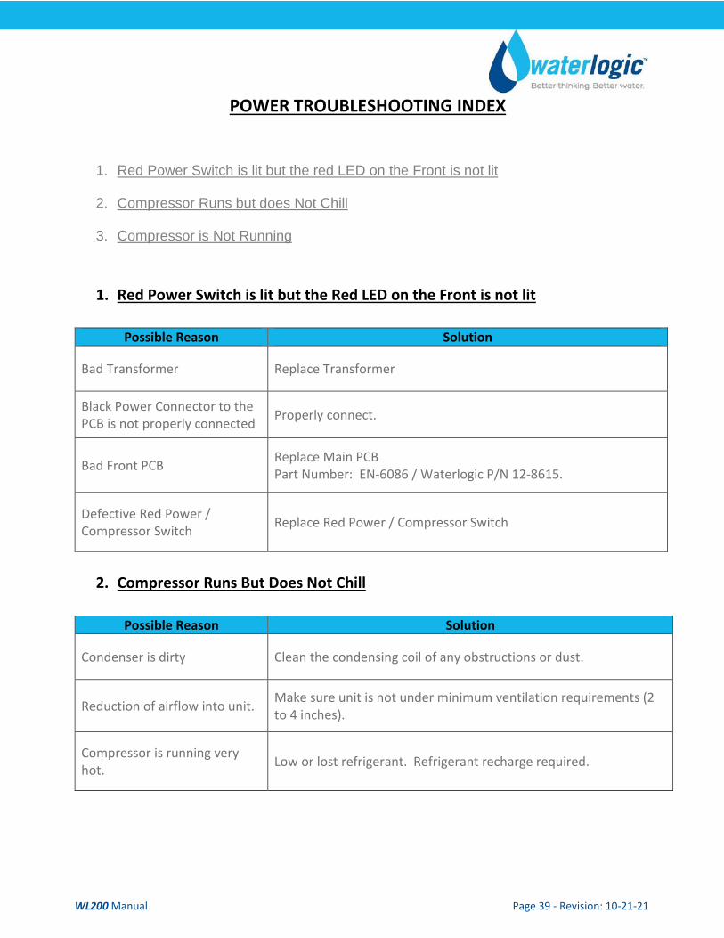
POWER TROUBLESHOOTING INDEX
1. Red Power Switch is lit but the red LED on the Front is not lit
2. Compressor Runs but does Not Chill
3. Compressor is Not Running
1. Red Power Switch is lit but the Red LED on the Front is not lit
Possible Reason Solution
Bad Transformer Replace Transformer
Black Power Connector to the PCB is not properly connected Properly connect.
Bad Front PCB Replace Main PCB Part Number: EN-6086 / Waterlogic P/N 12-8615.
Defective Red Power / Compressor Switch Replace Red Power / Compressor Switch
2. Compressor Runs But Does Not Chill
Possible Reason Solution
Condenser is dirty Clean the condensing coil of any obstructions or dust.
Reduction of airflow into unit. Make sure unit is not under minimum ventilation requirements (2 to 4 inches).
Compressor is running very hot. Low or lost refrigerant. Refrigerant recharge required.
WL200 Manual Page 40 - Revision: 10-21-21
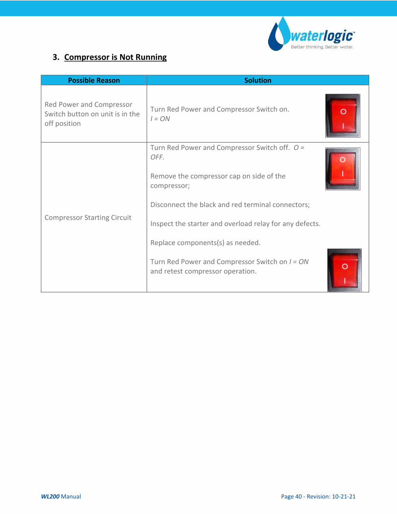
3. Compressor is Not Running
Possible Reason Solution
Red Power and Compressor Switch button on unit is in the off position
Turn Red Power and Compressor Switch on. I = ON
Compressor Starting Circuit
Turn Red Power and Compressor Switch off. O = OFF. Remove the compressor cap on side of the compressor; Disconnect the black and red terminal connectors; Inspect the starter and overload relay for any defects. Replace components(s) as needed. Turn Red Power and Compressor Switch on I = ON and retest compressor operation.
WL200 Manual Page 41 - Revision: 10-21-21
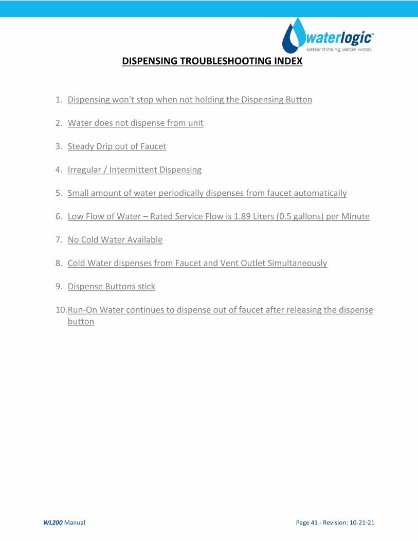
DISPENSING TROUBLESHOOTING INDEX
1. Dispensing won't stop when not holding the Dispensing Button
2. Water does not dispense from unit
3. Steady Drip out of Faucet
4. Irregular / Intermittent Dispensing
5. Small amount of water periodically dispenses from faucet automatically
6. Low Flow of Water – Rated Service Flow is 1.89 Liters (0.5 gallons) per Minute
7. No Cold Water Available
8. Cold Water dispenses from Faucet and Vent Outlet Simultaneously
9. Dispense Buttons stick
10. Run-On Water continues to dispense out of faucet after releasing the dispense
button
WL200 Manual Page 42 - Revision: 10-21-21
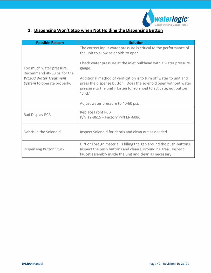
1. Dispensing Won’t Stop when Not Holding the Dispensing Button
Possible Reason Solution
Too much water pressure. Recommend 40-60 psi for the WL200 Water Treatment System to operate properly.
The correct input water pressure is critical to the performance of the unit to allow solenoids to open. Check water pressure at the inlet bulkhead with a water pressure gauge. Additional method of verification is to turn off water to unit and press the dispense button. Does the solenoid open without water pressure to the unit? Listen for solenoid to activate, not button “click”. Adjust water pressure to 40-60 psi.
Bad Display PCB Replace Front PCB P/N 12-8615 – Factory P/N EN-6086
Debris in the Solenoid Inspect Solenoid for debris and clean out as needed.
Dispensing Button Stuck Dirt or Foreign material is filling the gap around the push-buttons. Inspect the push buttons and clean surrounding area. Inspect faucet assembly inside the unit and clean as necessary.
WL200 Manual Page 43 - Revision: 10-21-21
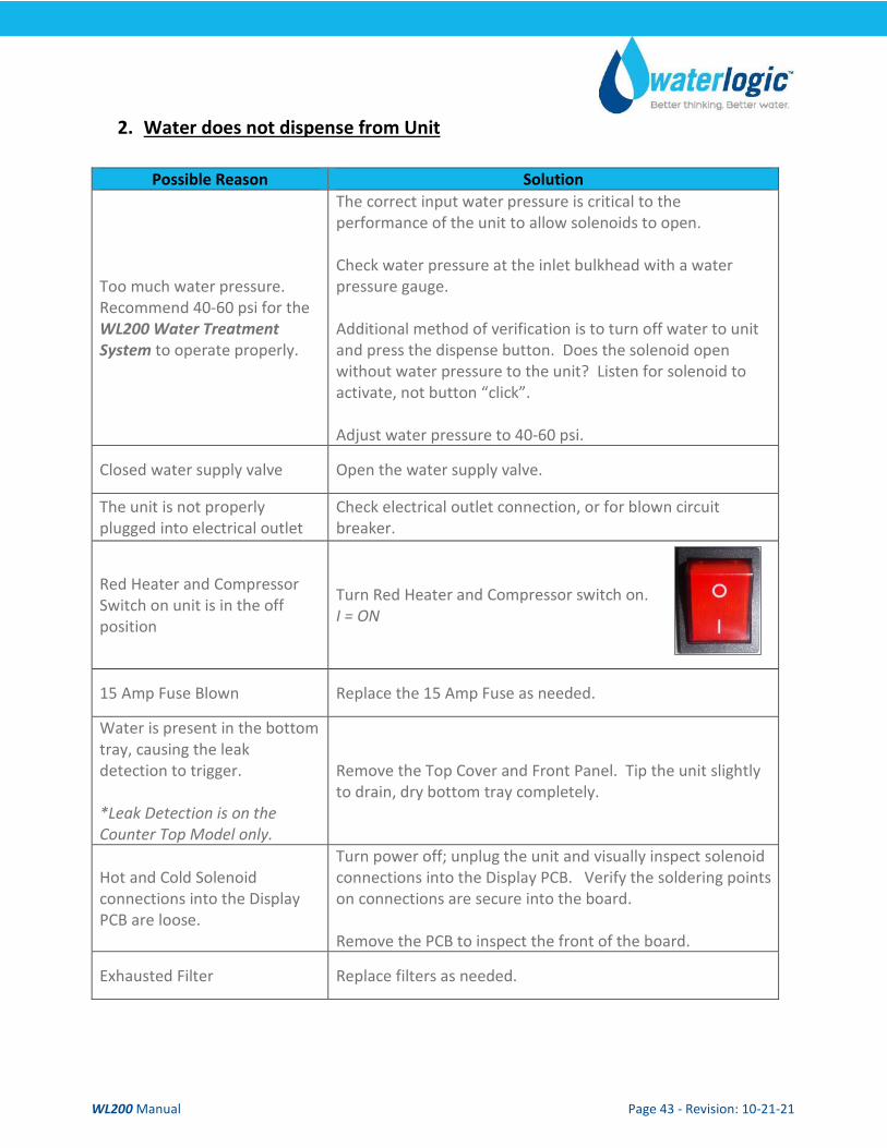
2. Water does not dispense from Unit
Possible Reason Solution
Too much water pressure. Recommend 40-60 psi for the WL200 Water Treatment System to operate properly.
The correct input water pressure is critical to the performance of the unit to allow solenoids to open. Check water pressure at the inlet bulkhead with a water pressure gauge. Additional method of verification is to turn off water to unit and press the dispense button. Does the solenoid open without water pressure to the unit? Listen for solenoid to activate, not button “click”. Adjust water pressure to 40-60 psi.
Closed water supply valve Open the water supply valve.
The unit is not properly plugged into electrical outlet
Check electrical outlet connection, or for blown circuit breaker.
Red Heater and Compressor Switch on unit is in the off position
Turn Red Heater and Compressor switch on. I = ON
15 Amp Fuse Blown Replace the 15 Amp Fuse as needed.
Water is present in the bottom tray, causing the leak detection to trigger. *Leak Detection is on the Counter Top Model only.
Remove the Top Cover and Front Panel. Tip the unit slightly to drain, dry bottom tray completely.
Hot and Cold Solenoid connections into the Display PCB are loose.
Turn power off; unplug the unit and visually inspect solenoid connections into the Display PCB. Verify the soldering points on connections are secure into the board. Remove the PCB to inspect the front of the board.
Exhausted Filter Replace filters as needed.
WL200 Manual Page 44 - Revision: 10-21-21
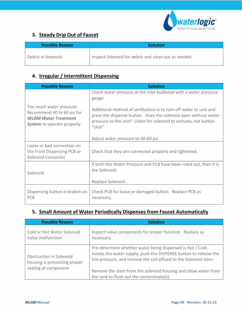
3. Steady Drip Out of Faucet
Possible Reason Solution
Debris in Solenoid Inspect Solenoid for debris and clean out as needed.
4. Irregular / Intermittent Dispensing
Possible Reason Solution
Too much water pressure. Recommend 40 to 60 psi for WL200 Water Treatment System to operate properly.
Check water pressure at the inlet bulkhead with a water pressure gauge. Additional method of verification is to turn off water to unit and press the dispense button. Does the solenoid open without water pressure to the unit? Listen for solenoid to activate, not button “click”. Adjust water pressure to 40-60 psi.
Loose or bad connection on the Front Dispensing PCB or Solenoid Connector
Check that they are connected properly and tightened.
Solenoid
If both the Water Pressure and PCB have been ruled out, then it is the Solenoid. Replace Solenoid.
Dispensing button is broken on PCB
Check PCB for loose or damaged button. Replace PCB as necessary.
5. Small Amount of Water Periodically Dispenses from Faucet Automatically
Possible Reason Solution
Cold or Hot Water Solenoid Valve malfunction`
Inspect valve components for proper function. Replace as necessary.
Obstruction in Solenoid housing is preventing proper sealing of component
Pre-determine whether water being dispensed is Hot / Cold. Isolate the water supply; push the DISPENSE button to release the line pressure, and remove the coil affixed to the Solenoid stem. Remove the stem from the solenoid housing and allow water from the tank to flush out the contaminate(s).
WL200 Manual Page 45 - Revision: 10-21-21
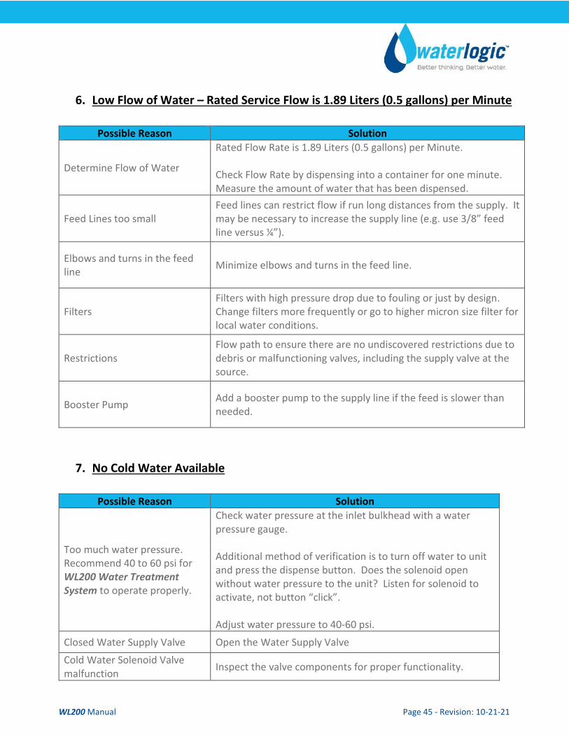
6. Low Flow of Water – Rated Service Flow is 1.89 Liters (0.5 gallons) per Minute
Possible Reason Solution
Determine Flow of Water
Rated Flow Rate is 1.89 Liters (0.5 gallons) per Minute. Check Flow Rate by dispensing into a container for one minute. Measure the amount of water that has been dispensed.
Feed Lines too small Feed lines can restrict flow if run long distances from the supply. It may be necessary to increase the supply line (e.g. use 3/8” feed line versus ¼”).
Elbows and turns in the feed line Minimize elbows and turns in the feed line.
Filters Filters with high pressure drop due to fouling or just by design. Change filters more frequently or go to higher micron size filter for local water conditions.
Restrictions Flow path to ensure there are no undiscovered restrictions due to debris or malfunctioning valves, including the supply valve at the source.
Booster Pump Add a booster pump to the supply line if the feed is slower than needed.
7. No Cold Water Available
Possible Reason Solution
Too much water pressure. Recommend 40 to 60 psi for WL200 Water Treatment System to operate properly.
Check water pressure at the inlet bulkhead with a water pressure gauge. Additional method of verification is to turn off water to unit and press the dispense button. Does the solenoid open without water pressure to the unit? Listen for solenoid to activate, not button “click”. Adjust water pressure to 40-60 psi.
Closed Water Supply Valve Open the Water Supply Valve Cold Water Solenoid Valve malfunction Inspect the valve components for proper functionality.
WL200 Manual Page 46 - Revision: 10-21-21
Red Heater and Compressor Switch on unit is off.
Turn Red Heater and Compressor Switch on. I = ON
Loose connection(s) on the Display PCB
Turn power off; unplug the unit and visually inspect solenoid connections into the Display PCB. Verify the soldering points on connections are secure into the board. Remove the PCB to inspect the front of the board.
Exhausted Filter Replace filters as needed.
8. Cold Water Dispenses from Faucet and Vent Outlet Simultaneously
Possible Reason Solution Improper tubing attachment from the tank to faucet or vice versa
Verify tubing is connected properly from tank outlets to correct faucet attachments.
Scale has formed inside cold tank outlet tube.
Remove cold water outlet tube from tank to faucet. Pour some scale remover into cold tank.
Expansion chamber in Cold Tank is not sealed properly. Replace Cold Tank.
WL200 Manual Page 47 - Revision: 10-21-21
9. Dispense Buttons Stick
Possible Reason Solution Dirt or Foreign material is filling the gap around the push-buttons.
Inspect the push buttons and clean surrounding area. Inspect faucet assembly inside the unit and clean as necessary.
10. Run On – Water continues to dispense out of faucet after releasing the dispense button
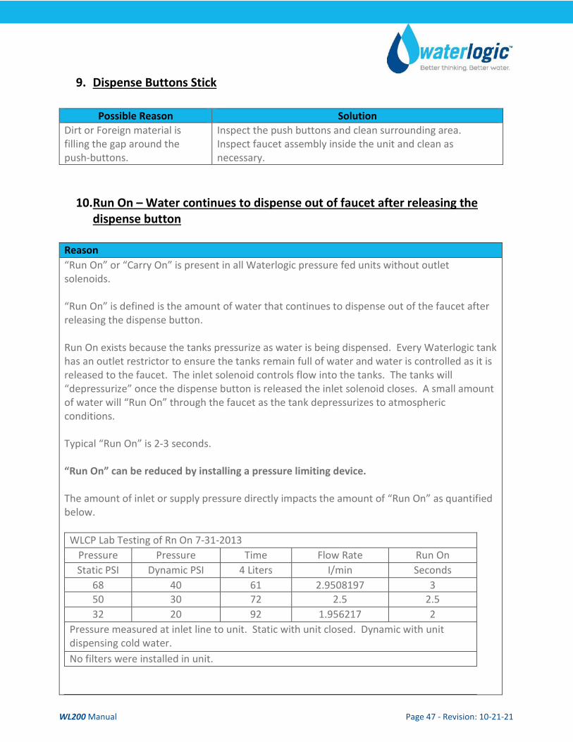
Reason “Run On” or “Carry On” is present in all Waterlogic pressure fed units without outlet solenoids. “Run On” is defined is the amount of water that continues to dispense out of the faucet after releasing the dispense button. Run On exists because the tanks pressurize as water is being dispensed. Every Waterlogic tank has an outlet restrictor to ensure the tanks remain full of water and water is controlled as it is released to the faucet. The inlet solenoid controls flow into the tanks. The tanks will “depressurize” once the dispense button is released the inlet solenoid closes. A small amount of water will “Run On” through the faucet as the tank depressurizes to atmospheric conditions. Typical “Run On” is 2-3 seconds. “Run On” can be reduced by installing a pressure limiting device. The amount of inlet or supply pressure directly impacts the amount of “Run On” as quantified below.
WLCP Lab Testing of Rn On 7-31-2013 Pressure Pressure Time Flow Rate Run On Static PSI Dynamic PSI 4 Liters I/min Seconds
68 40 61 2.9508197 3 50 30 72 2.5 2.5 32 20 92 1.956217 2
Pressure measured at inlet line to unit. Static with unit closed. Dynamic with unit dispensing cold water. No filters were installed in unit.
WL200 Manual Page 48 - Revision: 10-21-21
COLD WATER TROUBLESHOOT INDEX
1. Cold Water is not Cold 5°C ± -15°C (41° +/- 5° F)
1. Cold Water is not Cold 5°C ± -15°C (41° +/- 5° F)
Possible Reason Solution
No power or refrigeration elements
Check that the Red Power and Compressor switch is on. Turn Red Power and Compressor Switch on. I = ON
Tank has run out of cold water. Cold tank capacity is 4 liters for Tower and 2 liters for Counter Top.
Wait for cold tank to chill water to temperature prior to dispensing more cold water. A greater capacity of Waterlogic Water Systems is available.
Cold Water Thermostat Check continuity of thermostat with multimeter. Replace thermostat as required.
Refrigerant has run out Run compressor for at least ten minutes. If condenser is not warm, then refill the refrigerant.
Compressor problem If compressor is not running, repair or replacement is needed.