WIU Current Sensor, A80850
20
Siemens Mobility, Inc. 700 East Waterfront Drive Munhall, Pennsylvania 15120 1-800-793-SAFE www.usa.siemens.com/rail-manuals Copyright © 2011-2019 Siemens Mobility, Inc. User Guide WIU Current Sensor, A80850 DECEMBER 2011 (REVISED MARCH 2019) DOCUMENT NO. SIG-00-11-10 VERSION A.1
Transcript of WIU Current Sensor, A80850

Siemens Mobility, Inc. 700 East Waterfront Drive Munhall, Pennsylvania 15120 1-800-793-SAFE www.usa.siemens.com/rail-manuals Copyright © 2011-2019 Siemens Mobility, Inc.
User Guide
WIU Current Sensor, A80850 DECEMBER 2011 (REVISED MARCH 2019)
DOCUMENT NO. SIG-00-11-10 VERSION A.1

ii Document No.: SIG-00-11-10 Version: A.1
PROPRIETARY INFORMATION Siemens Mobility, Inc. has a proprietary interest in the information contained herein and, in some instances, has patent rights in the systems and components described. It is requested that you distribute this information only to those responsible people within your organization who have an official interest. This document, or the information disclosed herein, shall not be reproduced or transferred to other documents or used or disclosed for manufacturing or for any other purpose except as specifically authorized in writing by Siemens Mobility, Inc..
TRANSLATIONS The manuals and product information of Siemens Mobility, Inc. are intended to be produced and read in English. Any translation of the manuals and product information are unofficial and can be imprecise and inaccurate in whole or in part. Siemens Mobility, Inc. does not warrant the accuracy, reliability, or timeliness of any information contained in any translation of manual or product information from its original official released version in English and shall not be liable for any losses caused by such reliance on the accuracy, reliability, or timeliness of such information. Any person or entity who relies on translated information does so at his or her own risk.
WARRANTY INFORMATION Siemens Mobility, Inc. warranty policy is as stated in the current Terms and Conditions of Sale document. Warranty adjustments will not be allowed for products or components which have been subjected to abuse, alteration, improper handling or installation, or which have not been operated in accordance with Seller's instructions. Alteration or removal of any serial number or identification mark voids the warranty.
SALES AND SERVICE LOCATIONS Technical assistance and sales information on Siemens Mobility, Inc. products may be obtained at the following locations:
SIEMENS MOBILITY, INC. SIEMENS MOBILITY, INC. 2400 NELSON MILLER PARKWAY 939 S. MAIN STREET LOUISVILLE, KENTUCKY 40223 MARION, KENTUCKY 42064 TELEPHONE: (502) 618-8800 TELEPHONE: (270) 918-7800 FAX: (502) 618-8810 CUSTOMER
SERVICE: (800) 626-2710
SALES & SERVICE: (800) 626-2710 TECHNICAL SUPPORT:
(800) 793-7233
WEB SITE: USA Rail Automation Site FAX: (270) 918-7830
FCC RULES COMPLIANCE The equipment covered in this manual has been tested and found to comply with the limits for a Class A digital device, pursuant to part 15 of the FCC Rules. These limits are designed to provide reasonable protection against harmful interference when the equipment is operated in a commercial environment. This equipment generates, uses, and can radiate radio frequency energy and, if not installed and used in accordance with the instruction manual, may cause harmful interference to radio communications. Operation of this equipment in a residential area is likely to cause harmful interference in which case the user will be required to correct the interference at his expense.

iii Document No.: SIG-00-11-10 Version: A.1
Table Of Contents
Section Title Page PROPRIETARY INFORMATION .......................................... ii WARRANTY INFORMATION .............................................. ii SALES AND SERVICE LOCATIONS .................................... ii FCC RULES COMPLIANCE ................................................ ii TABLE OF CONTENTS ..................................................... iii LIST OF FIGURES ........................................................... iii NOTES, CAUTIONS, AND WARNINGS .............................. iv ELECTROSTATIC DISCHARGE (ESD) PRECAUTIONS ............ v
1 INTRODUCTION ............................................................................................................... 1-1
1.1 General ........................................................................................ 1-1 1.1.1 Current Sensor Board .................................................................... 1-1 1.1.2 Current Sensor Adapter Board ........................................................ 1-2 1.2 Ordering Information ..................................................................... 1-2
2 INSTALLATION ................................................................................................................. 2-1
2.1 Installation Overview ..................................................................... 2-1 2.1.1 Current Sensor Adapter Installation ................................................. 2-2 2.1.2 Current Sensor Wiring ................................................................... 2-3 2.1.2.1 Current Sensor Output Connection .................................................. 2-4 2.1.3 Surge Protection ........................................................................... 2-5 2.1.4 Current Sensor Module Expansion ................................................... 2-6 2.1.5 Threshold Settings ........................................................................ 2-7 2.1.6 Example Installations ..................................................................... 2-9
Table of Figures
Figure No. Title Page Figure 1-1 Current Sensor Module ............................................................... 1-1 Figure 1-2 Current Sensor Adapter Board ..................................................... 1-2 Figure 2-1 Typical Three Lamp Signal Current Sensor Installation .................... 2-1 Figure 2-2 Installed Current Sensor Adapter ................................................. 2-2 Figure 2-3 Current Sensor Wiring without Terminal Board Adapter .................. 2-3 Figure 2-4 Current Sensor Wiring with Terminal Board Adapter ....................... 2-3 Figure 2-5 Shielded Current Sensor Output Connections ................................ 2-4 Figure 2-6 Typical Installation with Surge Suppression ................................... 2-5 Figure 2-7 Current Sensor Module Expansion ................................................ 2-6 Figure 2-8 Multiple Expansion Modules (10 maximum) ................................... 2-6 Figure 2-9 Threshold Settings ..................................................................... 2-8 Figure 2-10 Example Current Sensor Installation ........................................... 2-9 Figure 2-11 Example of Current Sensing for Individual Signal Lamps ............. 2-10 Figure 2-12 Example of Current/Voltage Sensing ........................................ 2-11

iv Document No.: SIG-00-11-10 Version: A.1
NOTES, CAUTIONS, AND WARNINGS
Throughout this manual, notes, cautions, and warnings are frequently used to direct the reader’s attention to specific information. Use of the three terms is defined as follows:
NOTE
Generally used to highlight certain information relating to the topic under discussion.
CAUTION
REFERS TO PROPER PROCEDURES OR PRACTICES WHICH IF NOT STRICTLY OBSERVED, COULD RESULT IN A POTENTIALLY HAZARDOUS SITUATION AND/OR POSSIBLE DAMAGE TO EQUIPMENT. CAUTIONS TAKE PRECEDENCE OVER NOTES AND ALL OTHER INFORMATION, EXCEPT WARNINGS.
WARNING
INDICATES A POTENTIALLY HAZARDOUS SITUATION WHICH, IF NOT AVOIDED, COULD RESULT IN DEATH OR SERIOUS INJURY. WARNINGS ALWAYS TAKE PRECE-DENCE OVER NOTES, CAUTIONS, AND ALL OTHER INFORMATION.
If there are any questions, contact Siemens Mobility, Inc. Application Engineering

v Document No.: SIG-00-11-10 Version: A.1
ELECTROSTATIC DISCHARGE (ESD) PRECAUTIONS Static electricity can damage electronic circuitry, particularly low voltage components such as the integrated circuits commonly used throughout the electronics industry. Therefore, procedures have been adopted industry-wide which make it possible to avoid the sometimes invisible damage caused by electrostatic discharge (ESD) during the handling, shipping, and storage of electronic modules and components. Siemens has instituted these practices at its manufacturing facility and encourages its customers to adopt them as well to lessen the likelihood of equipment damage in the field due to ESD. Some of the basic protective practices include the following: • Ground yourself before touching card cages, assemblies, modules, or
components. • Remove power from card cages and assemblies before removing or installing
modules. • Remove circuit boards (modules) from card cages by the ejector lever only. If an
ejector lever is not provided, grasp the edge of the circuit board but avoid touching circuit traces or components.
• Handle circuit boards by the edges only. • Never physically touch circuit board or connector contact fingers or allow these
fingers to come in contact with an insulator (e.g., plastic, rubber, etc.). • When not in use, place circuit boards in approved static-shielding bags, contact
fingers first. Remove circuit boards from static-shielding bags by grasping the ejector lever or the edge of the board only. Each bag should include a caution label on the outside indicating static-sensitive contents.
• Cover workbench surfaces used for repair of electronic equipment with static
dissipative workbench matting. • Use integrated circuit extractor/inserter tools designed to remove and install
electrostatic-sensitive integrated circuit devices such as PROM’s (OK Industries, Inc., Model EX-2 Extractor and Model MOS-40 Inserter (or equivalent) are highly recommended).
• Utilize only anti-static cushioning material in equipment shipping and storage
containers. For information concerning ESD material applications, please contact the Siemens Technical Support Staff at 1-800-793-7233. ESD Awareness Classes and additional ESD product information are also available through the Technical Support Staff.

vi Document No.: SIG-00-11-10 Version: A.1
This Page Intentionally Left Blank

INTRODUCTION
1-1 Document No.: SIG-00-11-10 Version: A.1
SECTION 1 INTRODUCTION
1 INTRODUCTION
1.1 General The WIU (Wayside Interface Unit) current sensor is a component of the VIU and iVIU product lines. The WIU current sensor monitors signal lamp current to report if the lamp is off, on, or flashing. In PTC applications the current sensor monitors the energized state of the wayside signal lamps, and the signal aspect information is transmitted by the WIU to the locomotive.
1.1.1 Current Sensor Board The current sensor board is designed to monitor up to three lamps. The main board contains all the circuit components needed to create the digital outputs that represent the state of the lamps, including the sensors themselves. A Current Sensor Adapter board may be used to interface the lamp circuit to the current sensor board. Figure 1-1 displays the current sensor module.
Figure 1-1 Current Sensor Module

INTRODUCTION
1-2 Document No.: SIG-00-11-10 Version: A.1
1.1.2 Current Sensor Adapter Board The current sensor adapter board enables easy rerouting of the existing lamp wires through the sensors. By disengaging a single wire from its terminal and installing the small current sensor adapter board in its place, an extension loop (pre-wired through the sensor) is added to that lamp wire. This is accomplished in a relatively simple, easy, and minimally disruptive manner. Figure 1-2 shows the current sensor adapter board.
Figure 1-2 Current Sensor Adapter Board
1.2 Ordering Information The following is the ordering information for the WIU Current Sensor:
Part Number Description 8000-80850-0001 Current Sensor Module 62199 Current Sensor Adapter Board

INSTALLATION
2-1 Document No.: SIG-00-11-10 Version: A.1
SECTION 2 INSTALLATION
2 INSTALLATION
2.1 Installation Overview The current sensor system consists of two components, the current sensor and an optional current sensor adapter board. A typical three lamp signal installation is shown in Figure 2-1.
Figure 2-1 Typical Three Lamp Signal Current Sensor Installation
WARNING
VERIFY ALL COMPONENTS AND WIRING ARE PROPERLY INSTALLED AND MEET THE RAILROAD'S OR AGENCY'S APPROVED WIRING OR INSTALLATION DIAGRAM. FAILURE TO DO SO MAY LEAD TO INCORRECT OR UNSAFE OPERATION OF THE SIGNAL SYSTEM.
CAUTION
SIEMENS MOBILITY, INC. STRONGLY RECOMMENDS INSTALLING PRIMARY SURGE PROTECTION ON EXTERNAL LINES CONNECTING TO THE VIU.
NOTE
The WIU Current Sensor is not intended to be used for current sensing of Pulse Width Modulated (PWM) lamp detection.
Current Sensor Assembly
Existing Terminal Board
Terminal Board Connection with Current Sensor Adapter
To Lamp To
Lamp Wire
Lamp Wire
Lamp Wire 3
Sensor Connections

INSTALLATION
2-2 Document No.: SIG-00-11-10 Version: A.1
2.1.1 Current Sensor Adapter Installation The current sensor adapter is designed to retrofit existing signal control points and make them PTC-ready with minimal effort. Figure 2-1 shows the comparison of an existing terminal board and a modified terminal board with the current sensor adapter installed. Figure 2-2 displays a current sensor adapter mounted on a signal terminal block. The optional current sensor adapter cab be installed on each lamp terminal.
Figure 2-2 Installed Current Sensor Adapter

INSTALLATION
2-3 Document No.: SIG-00-11-10 Version: A.1
2.1.2 Current Sensor Wiring The wiring installation of the current sensor is shown in Figure 2-3 below. Lamp wiring is connected to the current sensor input connector J1. The input wires may be existing lamp wires or wires from the optional adapter board. Battery and the Vital Test Current Output are connected to J3. The vital test current output is picked up from the WIU device. The current sensor output (J2) is connected to the WIU device I/O using shielded cable.
Figure 2-3 Current Sensor Wiring without Terminal Board Adapter
Figure 2-4 Current Sensor Wiring with Terminal Board Adapter
J1
J2
J3
J4
J2
Cable Shield
+
-
+
-
+
-
+
-
+
-
VITAL DIGITAL INPUTS
VITAL TEST CURRENT OUTPUT
POWER INPUT
WIU
+ -
BATTERY
To Lamp
From Lamp Driver
Terminal Board
J1
J2
J3
J4 J2 Cable Shield
+
-
+
-
+
-
+
-
+
-
VITAL DIGITAL INPUTS
VITAL TEST CURRENT OUTPUT
POWER INPUT
WIU
+ -
BATTERY
To Lamp
Terminal Board
From Lamp Driver
Current Sensor Adapter Board
Existing Terminal

INSTALLATION
2-4 Document No.: SIG-00-11-10 Version: A.1
2.1.2.1 Current Sensor Output Connection The current sensor output (J2) is connected using a shielded cable. The shield is terminated at the current sensor output only as shown in Figure 2-5. Belden 9939 or equivalent cable is recommended.
CAUTION
USE CARE TO ENSURE THE ELIMINATION OF ANY FOREIGN ENERGY SOURCES.
CAUTION
ENSURE THAT THERE ARE NO SHORT CIRCUITS IN THE WIRING BETWEEN THE CURRENT SENSOR AND THE WIU.
NOTE
The shielded cable used in connecting the current sensor output to the WIU device I/O input has the shield terminated at the output source (current sensor). The shield is NOT connected at the WIU I/O to avoid creating a ground loop. Trim any excess shield wire flush with the wire insulation. Belden 9939 or equivalent cable is recommended.
Figure 2-5 Shielded Current Sensor Output Connections
CABLE SHIELD
BATTERY POSITIVE
J1
J2
J4
J2
J3
+
+
+
-
-
-
IN 3
IN 1
IN 2
WIU INPUTS
BELDEN 9939 OR EQUIVALENT
CURRENT SENSOR OUTPUTS ARE OPEN-COLLECTOR TRANSISTORS
SINKING CURRENT (INTERNALLY REFERENCED TO
BATTERY NEGATIVE)

INSTALLATION
2-5 Document No.: SIG-00-11-10 Version: A.1
2.1.3 Surge Protection Siemens Mobility, Inc. strongly recommends installing primary surge protection on external lines. A typical installation incorporating a surge suppressor on the wiring going to the signal lamp is shown in the figure below. Siemens Mobility, Inc. strongly recommends this type of installation.
CAUTION
SIEMENS MOBILITY, INC. STRONGLY RECOMMENDS INSTALLING PRIMARY SURGE PROTECTION ON EXTERNAL LINES CONNECTING TO THE VIU
Figure 2-6 Typical Installation with Surge Suppression
J1
J2
J3
J4 J2
To Lamp
Terminal Board
From Lamp Driver
Current Sensor Adapter Board
Existing Terminal
Surge Arrestor To
Earth Ground
INSTALLATION
2-6 Document No.: SIG-00-11-10 Version: A.1
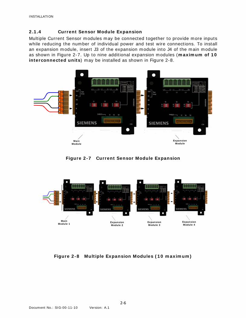
2.1.4 Current Sensor Module Expansion Multiple Current Sensor modules may be connected together to provide more inputs while reducing the number of individual power and test wire connections. To install an expansion module, insert J3 of the expansion module into J4 of the main module as shown in Figure 2-7. Up to nine additional expansion modules (maximum of 10 interconnected units) may be installed as shown in Figure 2-8.
Figure 2-7 Current Sensor Module Expansion
Figure 2-8 Multiple Expansion Modules (10 maximum)
Main Module 1 Expansion
Module 2 Expansion Module 3
Expansion Module 4
Main Module
Expansion Module
J1
J2
J3 J4
J1
J2
J3 J4

INSTALLATION
2-7 Document No.: SIG-00-11-10 Version: A.1
2.1.5 Threshold Settings The current sensor module has adjustable threshold settings for each input. The settings are adjusted via DIP switches located on the front of the unit. The DIP switch settings are shown in Figure 2-9.
WARNING
IT IS THE RAILROAD'S OR AGENCY'S RESPONSIBILITY THAT THE INSTALLATION IS FULLY OPERATIONALLY TESTED TO ENSURE SAFETY. SYSTEM OPERATION MUST BE VERIFIED PRIOR TO PLACING SYSTEM IN SERVICE.
WARNING
UNDER LIMITED CONDITIONS, LOW VOLTAGE FOREIGN ENERGY MAY TRIGGER A CURRENT SENSOR. WHEN THIS OCCURS, THE CURRENT SENSOR INDICATES THAT THE LAMP IS LIT EVEN THOUGH IT IS NOT. THIS HAZARD OCCURS MOST OFTEN WHEN USING INCANDESCENT LAMPS. TO AVOID THIS HAZARD, USE VOLTAGE SENSING COMBINED WITH CURRENT SENSING TO DETECT THE LAMP STATE.
NOTE
±1.03 Amps is the recommended setting for standard lamps and is the factory default setting. The ±0.65 Amps setting is reserved for future use.
NOTE
Ensure the threshold setting is set for ALL outputs.

INSTALLATION
2-8 Document No.: SIG-00-11-10 Version: A.1
Figure 2-9 Threshold Settings
Threshold - ±1.80 Amps
Threshold - ±1.42 Amps
Threshold - ±1.03 Amps (Factory Default)
Threshold - ±0.65 Amps (Reserved for future use)
A
A
A
A
B
B
B
B
OFF ON

INSTALLATION
2-9 Document No.: SIG-00-11-10 Version: A.1
2.1.6 Example Installations An example installation of a current sensor is shown in Figure 2-10 below. The installation includes a current sensor module and an expansion module. Six current sensor adapters are installed to provide the six lamp current to the sensor modules. Six surge suppressors are installed to protect the equipment from power and lightning surges. The current sensor modules are fed into an Siemens Mobility, Inc. VIU 16i that will supply data to a network via hardwire or data radio.
Figure 2-10 Example Current Sensor Installation

INSTALLATION
2-10 Document No.: SIG-00-11-10 Version: A.1
An example drawing of current sensing of the individual signal lamps using an Siemens Mobility, Inc. VIU and surge suppression is shown in Figure 2-11.
Figure 2-11 Example of Current Sensing for Individual Signal Lamps

INSTALLATION
2-11 Document No.: SIG-00-11-10 Version: A.1
An example drawing of a current/voltage sensing installation where current sensing is used on the lamp common and voltage sensing is used on the individual signal lamps is shown in Figure 2-12. The Siemens Mobility, Inc. VIU and surge suppression equipment is used in the installation.
Figure 2-12 Example of Current/Voltage Sensing

Siemens Mobility, Inc. 2400 Nelson Miller Parkway Louisville, Kentucky 40223
(502) 618-8800
Siemens Mobility, Inc. 939 South Main Street
Marion, Kentucky 42064 (270) 918-7800
Siemens Mobility, Inc. 700 East Waterfront Drive
Munhall, Pennsylvania 15120 1-800-793-SAFE