WITH RUGGED RADIAL-BLADE WHEELS · THE NEW YORK BLOWER COMPANY 7660 Quincy Street ... WITH RUGGED...
12
BULLETIN 231 JULY, 2009 THE NEW YORK BLOWER COMPANY 7660 Quincy Street Willowbrook, IL 60527-5530 Visit us on the Web: http://www.nyb.com Phone: (800) 208-7918 Email: [email protected] SERIES 20 GI FANS • Capacities to 77,000 CFM • Static pressures to 22”WG COMPACT GI FANS WITH RUGGED RADIAL-BLADE WHEELS SERIES 45 GI FANS • Capacities to 100,000 CFM • Static pressures to 46”WG SERIES 30 GI FANS • Capacities to 95,000 CFM • Static pressures to 32”WG DIRECT DRIVE BELT DRIVE • Capacities to 2,200 CFM • Static pressures to 14”WG • Temperatures to 600°F.
-
Upload
truongduong -
Category
Documents
-
view
217 -
download
0
Transcript of WITH RUGGED RADIAL-BLADE WHEELS · THE NEW YORK BLOWER COMPANY 7660 Quincy Street ... WITH RUGGED...

BULLETIN 231JULY, 2009
THE NEW YORK BLOWER COMPANY7660 Quincy StreetWillowbrook, IL 60527-5530
Visit us on the Web: http://www.nyb.comPhone: (800) 208-7918 Email: [email protected]
SERIES 20 GI FANS• Capacities to 77,000 CFM• Static pressures to 22”WG
COMPACTGI FANSWITH RUGGED RADIAL-BLADE WHEELS
SERIES 45 GI FANS• Capacities to 100,000 CFM• Static pressures to 46”WG
SERIES 30 GI FANS• Capacities to 95,000 CFM• Static pressures to 32”WG
DIRECTDRIVE
BELTDRIVE
• Capacities to 2,200 CFM
• Static pressures to 14”WG
• Temperatures to 600°F.

Compact GI Fans, sometimes referred to as pressure blowers, are ruggedly constructed for awide variety of industrial air-handling processes.
TYPICAL APPLICATIONS
• Dust collection
• Grinding-booth exhaust
• Scrubber exhaust
• Food and drying ovens
• Sawdust and wood-chip conveying
• Paper-trim systems
This bulletin covers only Compact GI Fans, thelower capacity element of four nyb radial-bladefan lines which cover a wide range of perfor-mance and application requirements. The designparameters and standard features of theCompact GI Fan are listed below.
• 8” through 14” wheel diameters providecapacities to 2200 CFM and 14”SP.
• Temperatures to 600°F.
• Heavy-gauge welded steel housing and pedestalprovide structural strength and durability.
• Lubricatable self-aligning ball bearings with cast-iron housings provide extended service life overfull catalog range.
... for industrialair-handling processes
COMPACT GI FANS
PAGE 2
Copyright © 2009 by The New York Blower Company.
Arrangement 9X Compact GI Fanwith flanged outlet, heat fan
construction, belt guard, motor, and v-belt drive.
AMCA SEALThe New York Blower Company certifiesthat the Compact GI Fans shown herein arelicensed to bear the AMCA Seal. The ratings shown are based on tests and procedures performed in accordance withAMCA Publication 211 and comply withthe requirements of the AMCA CertifiedRatings Program.
ALUMINUM
• 200°F. maximum temperature
• Spark-resistant
• Corrosion-resistant
• Clean-air applications
• Low cost
NICKEL-ALUMINUMBRONZE [NAB]
• 600°F. maximum temperature
• Spark-resistant
• Corrosion-resistant
• Abrasion-resistant
• Material-handling
CASTRADIAL-BLADEWHEEL
• Fan housing and pedestal are finished with agreen polyester powder coating.
• Most sizes are rotatable to any of seven standarddischarges in the field.
• Compact GI Fans offer stable pulsation-freeperformance from wide-open to closed-off.
Arrangement 4V Compact GI Fan with motor.

PAGE 3
ARRANGEMENTS
ARRANGEMENT
1BELT DRIVE
V-belt drive configuration allows selection of anyof six fan sizes at a variety of fan speeds.Provides flexibility in performance simply by adjusting or changing drive sheaves. Maximum temperatures: 200°F.-aluminumwheel; 300°F.-NAB wheel; 600°F.-heat fan.
MOTOR-POSITION DESIGNATIONDrawing at right showsAMCA motor-position desig-nations. This designationmust be given when order-ing Arrangement 1 fanswith V-belt drives and/orbelt guard. Motor positionsare independent of rotationand discharge and aredetermined by viewing fanshaft from drive end.
ARRANGEMENT
9BELT DRIVE
Compact V-belt drive configuration integratesmotor and drive with fan in one assembly.Package allows factory assembly and testing,and minimizes costly field labor. Available in sixsizes. Maximum temperatures: 200°F.-aluminumwheel; 300°F.-NAB wheel. See page 11 for maximum motor sizes.
ARRANGEMENT
9XBELT DRIVE
Used when motor is too large for Arrangement 9or when a higher temperature package is desired.Maximum temperatures: 200°F.–aluminumwheel; 300°F.-NAB wheel; 600°F-heat fan. Seepage 11 for maximum motor sizes.
ARRANGEMENT
4DIRECT DRIVE
Direct-drive configuration available in nine sizesat 3500 RPM and 1750 RPM, provides simplest, most economical package. Fan wheelis mounted on motor shaft. Not recommendedfor heavy material-handling applications asmaterial impact may damage motor. Maximumtemperature-180°F.
Similar to Arrangement 4, but designed for verti-cal mounting on fan inlet. Motor is mounted tothe drive-side plate, and the inlet plate is rein-forced for mounting direct to the process.Maximum temperature-120°F.
ARRANGEMENT
4VDIRECT DRIVE
Z
Y
W
X
PAGE 4
• FLANGED INLETFlange ring with holes is welded flush to the outer edgeof the inlet collar. See page 9 for inlet flange dimensions.
• INLET FILTERFilters are available with a choice of three element types:Wire mesh, hi-flow polyester, and ultra-synthetic. High-efficiency filter is flange mounted, and is furnished with aprotective hood. Outboard end of filter should be sup-ported independently of fan.
• FLANGED OUTLETFlange is welded flush with fan outlet and provided withholes. See page 9 for outlet flange dimensions.
• OUTLET DAMPERSingle-vane damper slips over fan outlet for all dischargesexcept Down Blast. Also available with flanges for mount-ing to fan flange and ductwork.
• WEATHER COVERAvailable for Arrangement 9 and Arrangement 4 fans.
• TEFLON SHAFT HOLE CLOSUREAttached inside housing at the shaft hole opening. Notavailable for Arrangement 4V fans, or with heat fan orspark-resistant construction.
• CERAMIC-FELT SHAFT SEALCeramic-felt seal e lements compressed between housingdrive-side plate and retaining disc…elements can be splitfor field replacement. Not available with heat-fan construction or Arrangement 4 or 4V fans.
• DRAINA 3⁄8” close pipe nipple located at the lowest point in thehousing scroll.
• VIBRATION ISOLATIONRubber-in-shear isolators…minimize the transmission ofvibration and noise to surrounding structures fromArrangement 4, 9, and 9X fans.
• SCREENED OUTLET RAINHOODFor Arrangement 4V fans, slips over fan outlet to protectfan airstream from the weather .
• SAFETY GUARDSArrangement 9 and 9X fans can be equipped with beltguards, and shaft and bearing guards. Belt guards forArrangement 1 fans are available on application.
• OTHER ACCESSORIESAlso available from nyb are inlet screens, outlet guards,motors, and v-belt drive components.
ACCESSORIES
Safety accessories are available from nyb, but selection of the appropriate devices is the responsibility of the system-designer who is familiar with the particular installation, orapplication, and can provide for guards for all exposed moving parts as well as protection fromaccess to high-velocity airstreams. Neither nyb nor its sales representatives is in a position tomake such determination. Users and/or installers should read “Recommended SafetyPractices for Air Moving Devices” as published by the Air Movement and Control AssociationInternational, Arlington Heights, Illinois.
SAFETYEQUIPMENT
Arrangement 9 Compact GI Fan with flanged inlet,flanged outlet, and weather cover.
Arrangement 9X Compact GI Fan with flanged inlet,flanged outlet, belt guard, shaft & bearing guard, motor, and v-belt drive components.
Arrangement 4 Compact GI Fan with motor and slip-type outlet damper.

HEAT-FANCONSTRUCTIONArrangement 1 and 9XCompact GI Fans withNAB wheels can beequipped with shaftcoolers which makethem suitable forairstream tempera-tures to 600°F., pro-vided that ambient air temperature at the bearingsdoes not exceed 120°F. The maximum allowablefan speed decreases as the airstream temperatureincreases. See Chart I [below].
*Maximum temperature for aluminum wheels is 200°F.Note: No derate required for SST wheel construction.
PAGE 5
• SPARK-RESISTANT CONSTRUCTIONThree types of spark-resistant construction are available.See separate nyb Engineering Letter and consult nyb salesrepresentative.
• HANDLING CORROSIVESProtective coating and special alloys are available to com-bat corrosion problems.Thin film coatings [5 to 10 mil thickness]—special paintsand spray coatings are available under a variety of tradenames. nyb works with experienced coating applicators whocan apply coatings to meet a wide range of requirements.Alternate material construction—Compact GI Fans canbe constructed of aluminum or various stainless steels.
MODIFICATIONS
DIRECT DRIVEThe curves and capacity tables on pages 6 and 7 provide CFM, staticpressure, BHP, and outlet velocity information for direct-drive Compact GIFans [see page 10 for maximum motor frame sizes].
BELT DRIVEThe capacity tables on pages 8 and 9 provide CFM, static pressure, BHP,and outlet velocity information for belt-drive Compact GI Fans. The dimen-sion tables on page 11 provide V-belt drive center-distance informationand maximum motor frames allowable.
All performance data is based on standard air at .075 lb./cu. ft. density[70°F. at sea level]. If selections are to be based on other temperatures oraltitudes, static pressure and brake horsepower must be corrected usingthe factors shown in Charts ll and lll. If temperature is a factor, speedmust be checked against the safe operating speed in Chart l. Note:Arrangement 4 fans are not suitable for temperatures over 180°F., andArrangement 4V fans are not suitable for temperatures over 120°F.
EXAMPLE
Select a Compact GI Fan with NAB wheel for 609 CFM at 3000 FPM OVat 2”SP at 325°F. at sea level.1. Chart ll shows a 1.48 correction factor for 325°F.2. 2”SP x 1.48 = 2.96”SP at 70°F. [round to 3”SP].3. A Size 106 Compact GI Fan belt drive at 2889 RPM will deliver 609
CFM and 3000 FPM outlet velocity at 3”SP, using .75 BHP.4. To determine static pressure and brake horsepower at conditions,
divide the values in Step 3 by the correction factor identified in Step 1:3”SP at 70°F. ÷ 1.48 = 2”SP at 325°F..75 BHP at 70°F. ÷ 1.48 = .51 BHP at 325°F.
5. Actual performance of the Size 106 Compact GI Fan:609 CFM at 3000 OV at 2”SP at 2889 RPM at .51 BHP at 325°F.
6. Check the safe operating speed of a Size 106 Compact GI Fan withNAB wheel at 325°F. Chart l shows a 4600 RPM safe speed at 325°F.which is greater than the 2889 RPM operating speed.
The method of correcting for altitude is the same as for temperature usingthe correction factors from Chart lll.
CHART IIISP AND BHPCORRECTIONFACTORS FOR
ALTITUDE [if above sea level]
Altitude Factor0 1.00
500 1.021000 1.041500 1.062000 1.08
2500 1.103000 1.123500 1.144000 1.164500 1.18
5000 1.205500 1.226000 1.256500 1.277000 1.30
7500 1.328000 1.358500 1.379000 1.40
10000 1.45
CHART IISP AND BHPCORRECTIONFACTORS FOR
TEMP. (°F.)Temp. Factor–50° 0.77–25° 0.82
0° 0.8720° 0.9140° 0.9460° 0.9870° 1.0080° 1.02
100° 1.06120° 1.09140° 1.13160° 1.17180° 1.21200° 1.25225° 1.29250° 1.34
275° 1.39300° 1.43325° 1.48350° 1.53375° 1.58400° 1.62450° 1.72500° 1.81550° 1.91600° 2.00
NOTE: If correction factor for both tem-perature and altitude is required, multi-ply factors from Charts ll and lll together:
600°F. and 3000’2.00 x 1.12 = 2.24[combined factor]
CHART IMAXIMUM SAFE SPEEDS FOR
BELT-DRIVE FANS WITH NAB WHEELS AT VARIOUS TEMPERATURES
Temp.85 105-106 125-126 146
Fan size
–50°* 4800 4600 4000 360070°* 4800 4600 4000 3600
200°* 4800 4600 4000 3600
300° 4800 4600 3980 3570400° 4800 4600 3960 3490500° 4800 4600 3940 3410600° 4800 4600 3860 3310
HOW TO USEPERFORMANCE TABLES

PAGE 6
Size HPInletdia.OD
Outletarea
sq. ft.
1⁄2"SP 3⁄4"SP 1"SP 11⁄2"SP 2"SP 21⁄2"SP 3"SPCFM OV BHP CFM OV BHP CFM OV BHP CFM OV BHP CFM OV BHP CFM OV BHP CFM OV BHP
85
95
105
106
125
116
126
136
146
5
6
6
6
7
7
8
8
8
0.103
0.126
0.126
0.203
0.158
0.255
0.255
0.293
0.293
199 1932 0.16
298 2365 0.21
- - -
533 2626 0.31
677 4285 0.48
802 3145 0.45
978 3835 0.60
- - -
1091 3724 0.95
151 1466 0.15
250 1984 0.20
338 2683 0.25
469 2310 0.29
632 4000 0.46
724 2839 0.42
911 3573 0.57
- - -
1050 3584 0.93
95 922 0.14
194 1540 0.18
294 2333 0.23
405 1995 0.27
585 3703 0.44
634 2486 0.39
836 3278 0.53
994 3392 0.74
1006 3433 0.91
176 1397 0.19
267 1315 0.22
484 3063 0.39
468 1835 0.34
687 2694 0.48
853 2911 0.67
915 3123 0.87
365 2310 0.33
215 843 0.25
519 2035 0.41
703 2399 0.59
828 2826 0.83
555 1894 0.52
727 2481 0.77
326 1113 0.39
605 2065 0.69
1⁄41⁄41⁄41⁄21⁄21⁄23⁄43⁄4
1
Performance certified is for installation type D: Ducted inlet, Ducted outlet.Performance ratings do not include the effects of appurtenances (accessories).
DIRECT-DRIVE CAPACITY TABLE AT 1750 RPM
0.0
0.5
1.0
1.5
2.0
2.5
3.0
3.5
4.0
0 200 400 600 800 1,000 1,200CFM
.09
.33.22
.35
.12
.24
.17
.20
.28
.60
.45.30
.54
.45.72
.82.42
.35
.26.19
.50
SIZE 106SIZE 116
SIZE 126
SIZE 136
SIZE 146
STATI
C P
RES
SUR
E [I
NC
HES
WG
]
Sizes 106, 116, 126, 136, 146
0.0
0.5
1.0
1.5
2.0
2.5
3.0
0 100 200 300 400 500 600 700 800CFM
.04
.06
.06
.08
.11
.10
.07
.17
.14
.10
.20
.30
.40
SIZE 125
SIZE 105
SIZE 95
SIZE 85
STATI
C P
RES
SUR
E [I
NC
HES
WG
]
Sizes 85, 95, 105, 125
DIRECT-DRIVE PERFORMANCE CURVES – 1750 RPMThe numbers within each graph represent brake horsepower values at various points of operationalong the curves.
CURVE SELECTION EXAMPLE: Select a fan for 800 CFM at 2" SP. Locate the desired point of operation on the grid in the graphs below, and follow the vertical line up to the nearest performancecurve, which is for the Size 146 Compact GI Fan. This fan will deliver 800 CFM at 2.25" SP at approximately 0.72 BHP.

PAGE 7
Size HPInletdia.OD
Outletarea
sq. ft.
2"SP 3"SP 4"SP 5"SP 6"SP 7"SP 8"SP 10"SPCFM OV BHP CFM OV BHP CFM OV BHP CFM OV BHP CFM OV BHP CFM OV BHP CFM OV BHP CFM OV BHP
8595
105105106106125125116116126126136146
56666677778888
0.1030.1260.1260.1260.2030.2030.1580.1580.2550.2550.2550.2550.2930.293
399 3874 0.56595 4722 0.99
- - -758 6016 1.39
- - -1067 5256 1.78
- - -- - -- - -
1603 6286 2.88- - -
1956 7671 4.07- - -
2183 7451 6.92
302 2932 0.48500 3968 0.89
- - -676 5365 1.26
- - -938 4620 1.59
- - -1264 8000 2.99
- - -1448 5678 2.65
- - -1823 7149 3.84
- - -2099 7164 6.75
388 3079 0.76- - -
587 465 1.14809 3985 1.42809 3985 1.42
- - -1169 7399 2.81
- - -1268 4973 2.42
- - -1672 6557 3.57
- - -2013 6870 6.59
262 2079 0.64476 3778 0.98476 3778 0.98682 3360 1.26682 3360 1.26
- - -1068 6759 2.60
- - -1102 4322 2.23
- - -1522 5969 3.331848 6307 4.931924 6567 6.45
353 2802 0.83353 2802 0.83533 2626 1.07533 2626 1.07
- - -968 6127 2.40
- - -936 3671 2.02
- - -1373 5384 3.131705 5819 4.621829 6242 6.27
- - -861 5449 2.20738 2894 1.73738 2894 1.73
1218 4776 2.901218 4776 2.901557 5314 4.311741 5942 6.11
730 4620 1.98730 4620 1.98430 1686 1.32430 1686 1.32
1038 4071 2.611038 4071 2.611406 4799 4.011656 5652 5.95
1111 3792 3.421453 4959 5.46
3⁄411
11⁄211⁄222323355
71⁄2
Performance certified is for installation type D: Ducted inlet, Ducted outlet.Performance ratings do not include the effects of appurtenances (accessories).
DIRECT-DRIVE CAPACITY TABLE AT 3500 RPM
0.0
2.0
4.0
6.0
8.0
10.0
12.0
14.0
16.0
0 250 500 750 1,000 1,250 1,500 1,750 2,000 2,250 2,500CFM
.58
1.0
1.9
1.3
2.0
3.0
2.3
1.5
1.23.2
2.0
3.6
2.9
5.5
4.2
2.7
4.1
6.5
SIZE 146
SIZE 136
SIZE 126
SIZE 116SIZE 106
STATI
C P
RES
SUR
E [I
NC
HES
WG
]
Sizes 106, 116, 126, 136, 146
0.0
2.0
4.0
6.0
8.0
10.0
12.0
0 200 400 600 800 1,000 1,200 1,400 1,600CFM
.30
.46
.52
.90
.70
.47
1.7
1.0
1.4
1.1
.80
3.2
2.48
SIZE 125
SIZE 105
SIZE 95SIZE 85
STA
TIC
PR
ESSU
RE
[IN
CH
ES W
G]
Sizes 85, 95, 105, 125
DIRECT-DRIVE PERFORMANCE CURVES – 3500 RPMThe numbers within each graph represent brake horsepower values at various points of operationalong the curves.
CURVE SELECTION EXAMPLE: Select a fan for 1250 CFM at 6" SP. Locate the desired point of operation on the grid in the graphs below, and follow the vertical line up to the nearest performancecurve, which is for the Size 126 Compact GI Fan. This fan will deliver 1250 CFM at 7.0" SP at approximately 2.9 BHP.

80 635 728 0.11 966 0.11 1159 0.12 1323 0.13 1857 0.17 2271 0.21 2636 0.26 2948 0.32 3247 0.38 3501 0.44 3755 0.52 3977 0.59 4201 0.67130 1032 832 0.11 1063 0.12 1242 0.13 1399 0.14 1890 0.19 2278 0.24 2628 0.30 2927 0.36 3209 0.43 3475 0.50 3715 0.58 3948 0.66 4166 0.74180 1429 963 0.12 1168 0.14 1341 0.15 1494 0.16 1974 0.22 2345 0.28 2668 0.35 2960 0.42 3231 0.50 3480 0.58 3702 0.66 3935 0.75 4157 0.84
230 1825 1113 0.14 1292 0.15 1453 0.17 1594 0.19 2065 0.26 2429 0.33 2744 0.41 3030 0.50 3279 0.58 3514 0.67 3746 0.76 3952 0.85 4166 0.96280 2222 1275 0.16 1436 0.18 1579 0.20 1710 0.22 2160 0.30 2528 0.39 2833 0.48 3104 0.57 3364 0.67 3595 0.77 3806 0.87 4019 0.98 4218 1.09330 2619 1446 0.19 1589 0.21 1720 0.24 1841 0.26 2270 0.35 2619 0.45 2931 0.56 3200 0.66 3451 0.77 3678 0.88 3883 0.99 4092 1.11 4281 1.23
380 3016 1622 0.24 1750 0.26 1873 0.28 1984 0.31 2384 0.41 2727 0.52 3031 0.64 3289 0.75 3544 0.88 3771 1.01 3980 1.13 4178 1.26 4360 1.38430 3413 1799 0.29 1919 0.32 2031 0.34 2137 0.37 2506 0.49 2835 0.60 3126 0.73 3394 0.86 3633 1.00 3857 1.13 4068 1.27 4273 1.42 4449 1.55480 3810 1979 0.35 2093 0.39 2192 0.42 2290 0.45 2643 0.57 2952 0.70 3233 0.84 3494 0.98 3738 1.13 3951 1.27 4164 1.43 4361 1.58 4546 1.73
530 4206 2161 0.43 2267 0.47 2362 0.50 2452 0.54 2783 0.67 3075 0.82 3351 0.96 3606 1.11 3838 1.26 4061 1.43 4266 1.59 4455 1.76580 4603 2345 0.53 2443 0.57 2535 0.61 2617 0.64 2937 0.79 3212 0.95 3470 1.10 3714 1.26 3952 1.43 4165 1.60 4361 1.77 4554 1.94630 5000 2532 0.64 2623 0.69 2710 0.73 2790 0.77 3086 0.93 3354 1.09 3599 1.26 3833 1.43 4060 1.61 4273 1.79 4471 1.97680 5397 2719 0.78 2802 0.82 2885 0.87 2963 0.91 3245 1.09 3503 1.26 3740 1.44 3960 1.62 4179 1.81 4391 2.01 4582 2.19
SIZE 105
PAGE 8
CFM OV1⁄4"SP
RPM BHP RPM BHP RPM BHP RPM BHP RPM BHP RPM BHP RPM BHP RPM BHP RPM BHP RPM BHP RPM BHP RPM BHP RPM BHP
1⁄2"SP 3⁄4"SP 1"SP 2"SP 3"SP 4"SP 5"SP 6"SP 7"SP 8"SP 9"SP 10"SP
Wheel diameter: 10" Inlet: 6" OD Outlet area: .126 sq. ft.
60 583 707 0.10 915 0.11 1218 0.11 1455 0.12 1663 0.13 2025 0.14 2329 0.16 2604 0.19 2852 0.21 3289 0.27 3680 0.33 4034 0.40 4349 0.47100 971 877 0.11 1060 0.11 1344 0.12 1576 0.13 1766 0.14 2102 0.16 2382 0.18 2641 0.21 2880 0.23 3310 0.30 3695 0.36 4042 0.44 4355 0.51140 1359 1073 0.11 1231 0.12 1494 0.13 1708 0.14 1895 0.16 2224 0.18 2493 0.21 2741 0.24 2959 0.27 3367 0.33 3730 0.40 4069 0.48 4384 0.56
180 1748 1283 0.13 1428 0.13 1659 0.15 1863 0.16 2041 0.18 2352 0.21 2623 0.24 2861 0.27 3092 0.31 3476 0.38 3823 0.46 4150 0.54 4442 0.62220 2136 1508 0.14 1630 0.15 1849 0.17 2029 0.19 2200 0.20 2499 0.24 2756 0.28 2994 0.32 3209 0.36 3603 0.44 3952 0.53 4257 0.62 4546 0.71260 2524 1741 0.17 1845 0.18 2046 0.20 2216 0.22 2373 0.24 2658 0.28 2908 0.32 3133 0.37 3338 0.41 3731 0.51 4067 0.60 4386 0.71 4665 0.81
300 2913 1979 0.20 2069 0.21 2245 0.24 2415 0.26 2561 0.28 2822 0.33 3063 0.38 3286 0.43 3494 0.48 3859 0.58 4197 0.69 4499 0.80 4799 0.92340 3301 2221 0.25 2300 0.26 2457 0.28 2612 0.31 2753 0.33 3005 0.39 3234 0.44 3452 0.50 3640 0.55 4009 0.66 4328 0.78 4627 0.90380 3689 2465 0.30 2535 0.31 2677 0.34 2818 0.37 2954 0.40 3199 0.46 3408 0.51 3609 0.57 3807 0.64 4156 0.76 4478 0.89 4765 1.01
420 4078 2711 0.37 2773 0.38 2902 0.41 3030 0.44 3157 0.48 3390 0.54 3597 0.60 3789 0.67 3978 0.74 4325 0.87 4632 1.01460 4466 2957 0.46 3014 0.47 3131 0.50 3249 0.53 3364 0.56 3590 0.63 3794 0.70 3973 0.77 4153 0.85 4482 0.99 4789 1.14500 4854 3205 0.56 3258 0.57 3364 0.60 3472 0.63 3579 0.67 3794 0.74 3993 0.82 4175 0.90 4342 0.98 4654 1.13540 5243 3454 0.67 3502 0.69 3601 0.72 3700 0.75 3799 0.79 3997 0.87 4191 0.95 4368 1.03 4530 1.12
SIZE 85CFM OV
1⁄8"SP
RPM BHP RPM BHP RPM BHP RPM BHP RPM BHP RPM BHP RPM BHP RPM BHP RPM BHP RPM BHP RPM BHP RPM BHP RPM BHP
1⁄4"SP 1⁄2"SP 3⁄4"SP 1"SP 11⁄2"SP 2"SP 21⁄2"SP 3"SP 4"SP 5"SP 6"SP 7"SP
Wheel diameter: 8" Inlet: 5" OD Outlet area: .103 sq. ft.
120 591 727 0.11 971 0.12 1169 0.13 1337 0.14 1859 0.18 2270 0.23 2623 0.29 2939 0.35 3219 0.42 3472 0.49 3727 0.57 3956 0.65 4166 0.73200 985 867 0.12 1077 0.13 1247 0.15 1401 0.16 1911 0.22 2306 0.29 2643 0.36 2947 0.43 3226 0.51 3472 0.60 3714 0.68 3928 0.77 4154 0.87280 1379 1028 0.14 1221 0.16 1379 0.17 1515 0.19 1976 0.26 2361 0.35 2703 0.44 2993 0.53 3253 0.62 3508 0.72 3743 0.83 3958 0.93 4160 1.03
360 1773 1196 0.17 1377 0.19 1528 0.21 1659 0.23 2085 0.32 2441 0.42 2767 0.53 3047 0.63 3317 0.75 3563 0.86 3799 0.99 4002 1.10 4212 1.23440 2167 1383 0.21 1545 0.23 1687 0.26 1811 0.29 2219 0.40 2559 0.51 2854 0.63 3121 0.75 3382 0.88 3622 1.01 3859 1.15 4063 1.29 4266 1.43520 2562 1576 0.26 1717 0.30 1851 0.33 1970 0.36 2368 0.49 2689 0.62 2966 0.75 3228 0.89 3463 1.03 3707 1.18 3921 1.33 4125 1.48 4332 1.65
600 2956 1774 0.34 1903 0.38 2020 0.41 2136 0.45 2520 0.60 2837 0.75 3104 0.90 3348 1.05 3577 1.20 3801 1.37 3999 1.52 4204 1.70 4396 1.87680 3350 1976 0.44 2094 0.48 2201 0.52 2305 0.56 2678 0.73 2980 0.90 3248 1.07 3487 1.24 3703 1.41 3914 1.58 4113 1.76 4307 1.94 4490 2.13760 3744 2182 0.56 2288 0.60 2390 0.65 2485 0.70 2842 0.89 3140 1.08 3396 1.27 3632 1.46 3839 1.64 4050 1.84 4241 2.03 4426 2.23
840 4138 2389 0.70 2488 0.76 2583 0.81 2670 0.86 3005 1.07 3292 1.28 3551 1.49 3777 1.70 3992 1.91 4185 2.12 4369 2.32 4558 2.54920 4532 2599 0.88 2688 0.94 2776 1.00 2861 1.05 3171 1.28 3454 1.51 3704 1.74 3928 1.97 4134 2.20 4328 2.43 4514 2.66
1000 4926 2810 1.09 2892 1.15 2975 1.22 3055 1.28 3347 1.53 3621 1.78 3862 2.03 4084 2.28 4289 2.53 4485 2.791080 5320 3022 1.34 3098 1.41 3175 1.47 3251 1.54 3526 1.81 3788 2.08 4025 2.35 4245 2.62 4449 2.90
SIZE 106CFM OV
1⁄4"SP
RPM BHP RPM BHP RPM BHP RPM BHP RPM BHP RPM BHP RPM BHP RPM BHP RPM BHP RPM BHP RPM BHP RPM BHP RPM BHP
1⁄2"SP 3⁄4"SP 1"SP 2"SP 3"SP 4"SP 5"SP 6"SP 7"SP 8"SP 9"SP 10"SP
Wheel diameter: 10" Inlet: 6" OD Outlet area: .203 sq. ft.
100 633 581 0.11 793 0.12 957 0.13 1098 0.14 1537 0.19 1878 0.25 2158 0.32 2423 0.40 2645 0.48 2860 0.57 3056 0.66 3247 0.77 3428 0.88170 1076 666 0.11 854 0.13 1006 0.14 1139 0.15 1572 0.22 1898 0.29 2181 0.37 2435 0.46 2660 0.55 2864 0.65 3058 0.76 3242 0.87 3422 0.99240 1519 780 0.13 941 0.14 1085 0.16 1207 0.17 1611 0.25 1941 0.33 2216 0.43 2460 0.52 2693 0.63 2892 0.74 3092 0.86 3270 0.98 3432 1.10
310 1962 900 0.15 1053 0.17 1178 0.18 1291 0.20 1676 0.29 1988 0.39 2258 0.49 2502 0.60 2732 0.72 2934 0.85 3121 0.97 3294 1.10 3472 1.25380 2405 1033 0.17 1170 0.20 1291 0.22 1393 0.24 1756 0.34 2050 0.45 2311 0.56 2546 0.68 2774 0.82 2978 0.96 3157 1.09 3337 1.24 3515 1.40450 2848 1172 0.21 1294 0.24 1407 0.27 1506 0.29 1843 0.40 2129 0.52 2381 0.65 2603 0.78 2819 0.92 3018 1.07 3198 1.22 3383 1.39 3551 1.55
520 3291 1315 0.26 1426 0.30 1528 0.33 1625 0.36 1946 0.48 2215 0.61 2463 0.76 2677 0.90 2878 1.05 3073 1.21 3256 1.37 3430 1.54 3590 1.71590 3734 1461 0.33 1563 0.36 1658 0.40 1748 0.44 2054 0.58 2312 0.72 2547 0.87 2765 1.03 2965 1.20 3140 1.36 3313 1.53 3479 1.71 3648 1.90660 4177 1610 0.41 1706 0.45 1793 0.49 1874 0.53 2173 0.69 2420 0.85 2639 1.00 2848 1.18 3038 1.35 3225 1.54 3393 1.72 3554 1.91 3705 2.10
730 4620 1762 0.51 1848 0.55 1930 0.60 2007 0.64 2291 0.82 2532 0.99 2740 1.16 2942 1.35 3126 1.53 3306 1.73 3469 1.93 3637 2.14 3786 2.34800 5063 1916 0.63 1993 0.68 2072 0.73 2143 0.78 2407 0.97 2645 1.16 2849 1.35 3039 1.53 3218 1.73 3393 1.95 3561 2.16 3716 2.38 3863 2.60870 5506 2070 0.78 2141 0.82 2213 0.88 2282 0.93 2536 1.14 2763 1.35 2964 1.56 3145 1.76 3321 1.97 3485 2.18 3650 2.41 3802 2.64 3948 2.88940 5949 2226 0.94 2292 1.00 2359 1.05 2425 1.11 2662 1.34 2882 1.57 3081 1.79 3260 2.01 3427 2.23 3582 2.44 3735 2.68 3885 2.92
SIZE 125CFM OV
1⁄4"SP
RPM BHP RPM BHP RPM BHP RPM BHP RPM BHP RPM BHP RPM BHP RPM BHP RPM BHP RPM BHP RPM BHP RPM BHP RPM BHP
1⁄2"SP 3⁄4"SP 1"SP 2"SP 3"SP 4"SP 5"SP 6"SP 7"SP 8"SP 9"SP 10"SP
Wheel diameter: 12" Inlet: 7" OD Outlet area: .158 sq. ft.
BELT-DRIVE CAPACITY TABLES
Performance certified is for installation type D: Ducted inlet, Ducted outlet. Power rating (BHP) does not include transmission losses.Performance ratings do not include the effects of appurtenances (accessories).

PAGE 9
180 614 665 0.13 909 0.16 1281 0.23 1571 0.32 1815 0.42 2030 0.53 2232 0.66 2407 0.78 2578 0.92 2735 1.06 2884 1.21 3166 1.53 3426 1.87300 1024 751 0.15 965 0.19 1301 0.29 1575 0.39 1814 0.51 2026 0.64 2224 0.78 2405 0.93 2565 1.07 2717 1.23 2873 1.41 3143 1.75 3399 2.13420 1433 874 0.19 1057 0.24 1362 0.36 1617 0.49 1838 0.62 2039 0.77 2227 0.93 2404 1.09 2566 1.26 2719 1.43 2870 1.62 3143 2.01 3393 2.42
540 1843 1018 0.25 1177 0.32 1448 0.45 1686 0.60 1898 0.76 2087 0.93 2263 1.10 2421 1.28 2576 1.47 2737 1.68 2875 1.87 3147 2.30 3390 2.73660 2253 1168 0.34 1316 0.42 1557 0.58 1774 0.75 1967 0.92 2154 1.11 2318 1.31 2477 1.51 2626 1.72 2769 1.94 2900 2.15 3154 2.60 3400 3.09780 2662 1324 0.45 1459 0.55 1682 0.74 1880 0.93 2061 1.13 2233 1.33 2397 1.55 2543 1.77 2689 2.00 2820 2.23 2953 2.48 3206 2.99 3425 3.48
900 3072 1486 0.61 1608 0.72 1821 0.94 1999 1.15 2173 1.37 2331 1.61 2478 1.84 2623 2.08 2760 2.32 2893 2.58 3019 2.84 3260 3.39 3487 3.961020 3481 1652 0.81 1763 0.92 1965 1.18 2131 1.42 2292 1.67 2440 1.91 2582 2.18 2714 2.44 2845 2.70 2973 2.98 3094 3.26 3327 3.84 3550 4.461140 3891 1821 1.05 1922 1.18 2109 1.47 2276 1.75 2418 2.02 2564 2.30 2698 2.57 2822 2.85 2943 3.14 3067 3.44 3185 3.75 3414 4.38
1260 4300 1992 1.35 2084 1.50 2258 1.80 2419 2.12 2557 2.42 2687 2.72 2820 3.03 2936 3.32 3056 3.64 3171 3.96 3281 4.28 3498 4.951380 4710 2164 1.71 2250 1.88 2413 2.20 2564 2.55 2704 2.89 2826 3.22 2943 3.54 3064 3.88 3177 4.21 3286 4.55 3388 4.88 3597 5.611500 5119 2338 2.13 2418 2.32 2568 2.66 2709 3.03 2846 3.41 2973 3.79 3082 4.14 3187 4.48 3300 4.86 3409 5.23 3511 5.591620 5529 2512 2.63 2587 2.83 2728 3.20 2863 3.60 2993 4.01 3117 4.42 3226 4.80 3327 5.18 3430 5.57 3533 5.97
SIZE 146CFM OV
1⁄2"SP
RPM BHP RPM BHP RPM BHP RPM BHP RPM BHP RPM BHP RPM BHP RPM BHP RPM BHP RPM BHP RPM BHP RPM BHP RPM BHP
1"SP 2"SP 3"SP 4"SP 5"SP 6"SP 7"SP 8"SP 9"SP 10"SP 12"SP 14"SP
Wheel diameter: 14" Inlet: 8" OD Outlet area: .293 sq. ft.
150 588 587 0.11 792 0.12 967 0.13 1111 0.15 1558 0.22 1903 0.30 2201 0.40 2456 0.50 2698 0.61 2915 0.73 3121 0.85 3304 0.98 3486 1.11250 980 677 0.12 862 0.14 1010 0.15 1137 0.17 1578 0.25 1920 0.35 2213 0.47 2464 0.59 2693 0.71 2909 0.85 3117 0.99 3307 1.14 3479 1.29350 1373 789 0.14 954 0.16 1091 0.18 1213 0.20 1604 0.29 1943 0.40 2234 0.53 2482 0.66 2719 0.82 2922 0.96 3126 1.13 3307 1.29 3492 1.47
450 1765 908 0.16 1063 0.19 1191 0.22 1304 0.24 1685 0.36 1983 0.47 2253 0.60 2504 0.75 2735 0.91 2949 1.08 3139 1.25 3328 1.44 3511 1.64550 2157 1037 0.20 1179 0.23 1300 0.26 1408 0.30 1765 0.43 2065 0.57 2311 0.71 2536 0.86 2764 1.02 2968 1.20 3165 1.39 3348 1.58 3529 1.79650 2549 1173 0.25 1300 0.28 1419 0.32 1520 0.36 1857 0.52 2137 0.68 2394 0.85 2610 1.01 2817 1.18 3003 1.35 3191 1.54 3368 1.74 3536 1.95
750 2941 1315 0.31 1429 0.35 1536 0.40 1635 0.44 1960 0.62 2230 0.80 2470 0.99 2688 1.18 2893 1.38 3080 1.57 3252 1.77 3412 1.96 3573 2.17850 3333 1460 0.40 1562 0.44 1660 0.49 1755 0.54 2069 0.74 2328 0.95 2555 1.15 2770 1.37 2974 1.59 3153 1.81 3330 2.03 3486 2.24 3643 2.46950 3725 1608 0.50 1702 0.55 1791 0.60 1877 0.66 2184 0.88 2431 1.11 2657 1.34 2864 1.58 3051 1.81 3232 2.05 3403 2.30 3568 2.55 3723 2.80
1050 4118 1758 0.63 1845 0.68 1926 0.74 2005 0.80 2302 1.04 2545 1.29 2759 1.55 2960 1.80 3141 2.06 3318 2.32 3485 2.59 3646 2.86 3799 3.141150 4510 1909 0.78 1989 0.84 2065 0.91 2138 0.97 2419 1.23 2659 1.50 2869 1.78 3059 2.05 3244 2.34 3409 2.62 3572 2.90 3731 3.20 3882 3.501250 4902 2061 0.96 2136 1.03 2208 1.10 2276 1.17 2541 1.45 2773 1.74 2980 2.04 3167 2.34 3342 2.64 3504 2.94 3665 3.25 3812 3.55 3962 3.871350 5294 2213 1.17 2284 1.25 2351 1.32 2416 1.39 2663 1.69 2894 2.01 3099 2.33 3277 2.64 3450 2.97 3611 3.30 3762 3.63 3909 3.95
SIZE 126CFM OV
1⁄4"SP
RPM BHP RPM BHP RPM BHP RPM BHP RPM BHP RPM BHP RPM BHP RPM BHP RPM BHP RPM BHP RPM BHP RPM BHP RPM BHP
1⁄2"SP 3⁄4"SP 1"SP 2"SP 3"SP 4"SP 5"SP 6"SP 7"SP 8"SP 9"SP 10"SP
Wheel diameter: 12" Inlet: 8" OD Outlet area: .255 sq. ft.
BELT-DRIVE CAPACITY TABLES
Performance certified is for installation type D: Ducted inlet, Ducted outlet. Power rating (BHP) does not include transmission losses.Performance ratings do not include the effects of appurtenances (accessories).
FLANGED INLET OPTIONFour 5⁄16” diameter holes furnished oncenterlines.NOTE–Inlet flange: 10 gauge.
FLANGED OUTLET OPTION1”x1”x1⁄8” angles are mounted flush with outside edgeof housing discharge. All sizes have 5⁄16” diameter corner holes. Sizes 136 and 146 have four additionalholes on centerline. Not available on Size 85 Arr. 4Bottom Horizontal and all Down Blast discharge fans.
OUTLETDAMPER OPTIONOutlet damper has the effect of extending the fan B dimension per the chartbelow. Damper outlet di-mensions are the same asfan outlet, D, and M. Forslip-connection damper only.
MATERIALSPECIFICATIONS
Housings
12 gauge 14 gaugeSizes 85-106: 12 gaugeSizes 116-146: 10 gauge
Link-Belt P3-U200 Series ball bearings or equal.
Pedestals and drive-side plates Inlet plates Bearings [Arr. 1, 9, 9X]
Size ID BC OD
85 5 6 7
95 6 7 8105 6 7 8106 6 7 8
116 7 8 9125 7 8 9126 8 9 10
136 8 9 10146 8 9 10
DIMENSIONS[INCHES]
Size A B D M
85 65⁄8 55⁄8 45⁄8 35⁄8
95 75⁄8 55⁄8 55⁄8 35⁄8105 75⁄8 55⁄8 55⁄8 35⁄8106 75⁄8 75⁄8 55⁄8 55⁄8
116 9 75⁄8 7 55⁄8125 9 55⁄8 7 35⁄8126 9 75⁄8 7 55⁄8
136 101⁄4 75⁄8 81⁄4 55⁄8146 101⁄4 75⁄8 81⁄4 55⁄8
DIMENSIONS [INCHES]
Size Damper extention
85 53⁄8”
95 57⁄8”105 57⁄8”106 57⁄8”
116 61⁄2”125 61⁄2”126 61⁄2”
136 73⁄4”146 73⁄4”
D
M
A
B
5/8"
5/8"5/8"

DIMENSIONS [INCHES]
Size B C D F G HH L M N R S T U W a b c d O.D. B.C. Arr. 4wt. [lbs.]*
Arr. 4Vwt. [lbs.]*
85 6 63⁄8 45⁄8 67⁄8 57⁄8 145⁄8 5 35⁄8 101⁄8 37⁄16 6 61⁄4 63⁄4 141⁄4 61⁄4 91⁄8 65⁄8 55⁄8 10 9 35 26
95 71⁄2 77⁄8 55⁄8 81⁄2 71⁄4 145⁄8 6 35⁄8 101⁄8 37⁄16 6 61⁄4 63⁄4 141⁄4 73⁄4 111⁄4 8 63⁄4 123⁄4 12 39 30105 71⁄2 77⁄8 55⁄8 81⁄2 71⁄4 145⁄8 6 35⁄8 101⁄8 37⁄16 6 61⁄4 63⁄4 141⁄4 73⁄4 111⁄4 8 63⁄4 123⁄4 12 40 31106 71⁄2 77⁄8 55⁄8 81⁄2 71⁄4 165⁄8 6 55⁄8 101⁄8 47⁄16 6 61⁄4 63⁄4 141⁄4 73⁄4 111⁄4 8 63⁄4 123⁄4 12 45 36
116 81⁄2 10 7 111⁄4 83⁄4 175⁄8 7 55⁄8 111⁄8 415⁄16 7 73⁄4 81⁄4 15 93⁄8 137⁄8 105⁄8 81⁄8 133⁄4 127⁄8 55 42125 81⁄2 10 7 111⁄4 83⁄4 155⁄8 7 35⁄8 111⁄8 315⁄16 7 73⁄4 81⁄4 15 93⁄8 137⁄8 105⁄8 81⁄8 133⁄4 127⁄8 55 42126 81⁄2 10 7 111⁄4 83⁄4 175⁄8 8 55⁄8 111⁄8 415⁄16 7 73⁄4 81⁄4 15 93⁄8 137⁄8 105⁄8 81⁄8 133⁄4 127⁄8 60 47
136 101⁄2 111⁄8 81⁄4 12 101⁄4 175⁄8 8 55⁄8 111⁄8 415⁄16 7 73⁄4 81⁄4 15 103⁄4 16 111⁄2 93⁄4 18 161⁄2 70 59146 101⁄2 111⁄8 81⁄4 12 101⁄4 175⁄8 8 55⁄8 111⁄8 415⁄16 7 73⁄4 81⁄4 15 103⁄4 16 111⁄2 93⁄4 18 161⁄2 70 59
ARRANGEMENT 4DIRECT-DRIVE DIMENSIONS
Size Motor frame A
48, 5648, 56, 143T, 145T
56, 143T, 145T56, 143T, 145T
182T, 184T56, 143T, 145T
182T, 184T143T, 145T182T, 184T
101⁄2
121⁄2131⁄2121⁄2131⁄2121⁄2131⁄2
85, 95105106
116, 125, 126
136
146
ARRANGEMENT 4VSize Motor frame H*
48C, 56C48C, 56C
143TC, 145TC56C
143TC, 145TC56C
143TC, 145TC182TC, 184TC
56C,143TC, 145TC182TC, 184TC143TC, 145TC182TC, 184TC
153⁄4-181⁄8153⁄4-181⁄8
195⁄8201⁄8215⁄8201⁄8215⁄8251⁄8181⁄8195⁄8231⁄8215⁄8251⁄8
85, 95
105
106
116, 126, 136
125
146
L is OD of collar. M and D are outside dimensions. W pertains to optional weather cover. *Bare fan weight, less motors. Tolerance: ± 1⁄8”Arr. 4 base holes and Arr. 4V mounting holes = 1⁄2”
*Range based on motor frame selected using standard duty TEFC motors.
BOTTOM HORIZONTAL
B
F G
C C B
TOP HORIZONTALCCW TH
A A
CCW BH CCW TADTOP ANGULAR DOWN
G F
B C
F G
UP BLASTCCW UB
A
CCW DB
A
DOWN BLAST BOTTOM ANGULAR UP
AA
CCW BAUTOP ANGULAR UP
CCW TAU
A
DOWN BLASTTOP HORIZONTALCW TH CW BH
BOTTOM HORIZONTALCW UB
UP BLAST
A
F
BC
A
G
A
B
CB GF
CW BAUBOTTOM ANGULAR UPTOP ANGULAR DOWN
CW TADCW DB CW TAUTOP ANGULAR UP
A
C
A A
FG
A
FAN DISCHARGES – VIEWED FROM DRIVE SIDE
◆ On Size 146 in Bottom Horizontal discharge with optional flanged outlet, the flange extends below the Arrangement 1 or 9 baseline.★ Down Blast discharge is not available in Arrangement 9X.
Clockwise—angular discharges at 45º Counterclockwise—angular discharges at 45º
PAGE 10
★ ★◆ ◆
7/8"HH
L
NMW
R S
T
T
U
U
DF G
B
AC
1 3/4"
DFG
B
C
M
H
O.D.
LB.C.
(8)-1/2"(13mm) DIA.MTG. HOLES ON C'SL

7/8"H
NM K
L
A+2 1 2"
P P
B
A
DF G
C
E
1"XWY
1"RRQ Q
2 1 2"
PAGE 11
BELT-DRIVE DIMENSIONS
ARRANGEMENT
1
ARRANGEMENT
9
Size Frame Min. Max.
485648
56/143/145
81⁄287⁄895⁄8
10
101⁄4105⁄8113⁄4121⁄8
85, 105, 106
125, 126, 146
MINIMUM-MAXIMUMV-BELT DRIVE CENTERS
[INCHES]
ARRANGEMENT
9X
Size Frame Min. Max.
4856/143/14556/143/145
182/184
14141⁄2161⁄8151⁄2
171⁄4165⁄8185⁄818
85, 105, 106
125, 126, 146
MINIMUM-MAXIMUMV-BELT DRIVE CENTERS
[INCHES]
DIMENSIONS [INCHES]Size A B C D E F G H K L M N P Q R RR S T U W
85 101⁄2 6 63⁄8 45⁄8 53⁄8 67⁄8 57⁄8 17 21⁄4 5 35⁄8 101⁄4 51⁄8 57⁄8 33⁄8 11⁄4 6 61⁄4 63⁄4 173⁄4105 101⁄2 71⁄2 77⁄8 55⁄8 65⁄8 81⁄2 71⁄4 17 21⁄4 6 35⁄8 101⁄4 51⁄8 57⁄8 33⁄8 11⁄4 6 61⁄4 63⁄4 173⁄4106 101⁄2 71⁄2 77⁄8 55⁄8 65⁄8 81⁄2 71⁄4 19 21⁄4 6 55⁄8 101⁄4 51⁄8 57⁄8 43⁄8 21⁄4 6 61⁄4 63⁄4 173⁄4125 121⁄2 81⁄2 10 7 71⁄2 111⁄4 83⁄4 201⁄8 3 7 35⁄8 125⁄8 71⁄8 77⁄8 3 11⁄8 101⁄2 81⁄8 85⁄8 207⁄8126 121⁄2 81⁄2 10 7 71⁄2 111⁄4 83⁄4 221⁄8 3 8 55⁄8 125⁄8 71⁄8 77⁄8 4 21⁄8 101⁄2 81⁄8 85⁄8 207⁄8146 121⁄2 101⁄2 111⁄8 81⁄4 93⁄8 12 101⁄4 221⁄8 3 8 55⁄8 125⁄8 71⁄8 77⁄8 4 21⁄8 101⁄2 81⁄8 85⁄8 207⁄8
Size WW X XX Y YY a b c d Max. motor length★Arr. 9 Arr. 9X Arr. 9 Arr. 9X
Shaftdia. Keyway Base
holesBare fan weights [lbs.]†Arr. 1 Arr. 9 Arr. 9X
85 145⁄8 61⁄4 131⁄2 26 51⁄2 61⁄4 91⁄8 65⁄8 55⁄8 91⁄2 127⁄8 56 145T 1 1⁄4 x 1⁄8 1⁄2 40 40 55105 145⁄8 61⁄4 131⁄2 26 51⁄2 73⁄4 111⁄4 8 63⁄4 91⁄2 127⁄8 56 145T 1 1⁄4 x 1⁄8 1⁄2 45 45 60106 145⁄8 61⁄4 131⁄2 26 51⁄2 73⁄4 111⁄4 8 63⁄4 91⁄2 127⁄8 56 145T 1 1⁄4 x 1⁄8 1⁄2 50 50 65125 175⁄8 81⁄8 145⁄8 31 73⁄8 93⁄8 137⁄8 105⁄8 81⁄8 113⁄4 127⁄8 145T 184T 1 1⁄4 x 1⁄8 1⁄2 60 60 85126 175⁄8 81⁄8 145⁄8 31 73⁄8 93⁄8 137⁄8 105⁄8 81⁄8 113⁄4 127⁄8 145T 184T 1 1⁄4 x 1⁄8 1⁄2 65 65 90146 175⁄8 81⁄8 145⁄8 31 73⁄8 103⁄4 16 111⁄2 93⁄4 113⁄4 127⁄8 145T 184T 1 1⁄4 x 1⁄8 1⁄2 80 80 105
L is OD of collar. M and D are outside dimensions. ★ Maximum motor length is NEMA C - NW dimension. † Less motors and V-belt drives.
“L” [left] motor position isshown. “R” [right] is oppositehand. NOTE: Select motor andfan discharge position so fandoes not discharge into motor.Down Blast discharge is notavailable in Arrangement 9X.
“L” [left] motor position is shown.“R” [right] is opposite hand.Select motor position so as not tointerfere with outlet connection.
7/8"H
L
NM K
B
A
DF G
C
E
R S
T
T
U
U
7/8" R S
T
T
U
U
L
NM K
B
A
DF G
C
E
WW XX YY
H
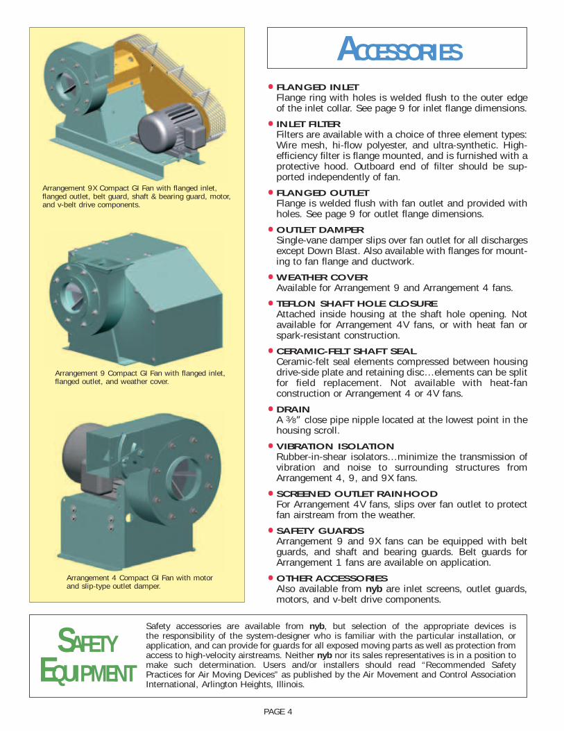
COMPLETE SELECTION OFAIR-MOVING EQUIPMENTThe New York Blower Company offers thousands of different types, models, andsizes of air-moving equipment. Contact your nyb representative for assistance inidentifying the best fan for your application.
Leading the industry forward since 1889
DUST/MATERIALHANDLING
Wide range of duty available with unique fan lines capable of handling light dust to heavymaterial. Typical applicationsinclude dust-collection and high-pressure process along with material-conveying.
ROOF VENTILATORSIncluding both hooded and upblast ventilators, propeller fans, and centrifugal roof exhausters. These units are ideal for industrial, commercial,and institutional applications.
PROCESS/FANCOMPONENTSPlug fans, plenum fans, wheels, inlet cones, and housings for a wide variety of OEM applications. Process/fan components are used in air-handling units, ovens, dryers, freezer tunnels, and filtration systems.
HEATINGPRODUCTSIndustrial-duty steam unit heaters with steam heating coils are availablefor facility heating andprocess-heat transfer.
AIR-HANDLING[CENTRIFUGAL]
Designed for clean to moderatelydirty gas streams. Commercial and industrial HVAC, process cooling, light material-conveying,heat removal, and dryer exhaustare just a few of the numeroussample applications
AIR-HANDLING[AXIAL]
For the ideal handling of cleanto moderately dirty airstreams.Commercial and industrial HVAC,drying and cooling systems, fumeextraction, and process-heatremoval are typical applications.
FIBERGLASSREINFORCED
PLASTIC [FRP]Choice of performance and duty forcorrosive gas streams. Applicationsinclude chemical process, wastewatertreatment, laboratory hood exhaust,and tank aeration.
CUSTOM PRODUCTSDesigned for unique applications. Variety of configurations, temperatures, flows, and pressures. Wide range of modifications and accessories are available to meet the most demanding specifications.