with EtherNet IP EVS58N-***-IZ EVM58N-***-IZ ESS58N-***-IZ...
39
Instruction Manual FACTORY AUTOMATION Absolute Rotary Encoder with EtherNet ✓ IP EVS58N-***-IZ EVM58N-***-IZ ESS58N-***-IZ ESM58N-***-IZ
Transcript of with EtherNet IP EVS58N-***-IZ EVM58N-***-IZ ESS58N-***-IZ...

Instruction Manual
FACTORY AUTOMATION
Absolute Rotary Encoderwith EtherNet�IP
EVS58N-***-IZEVM58N-***-IZESS58N-***-IZESM58N-***-IZ

Par
t. N
o. x
xxxx
x / D
OC
T-2
115A
/ 24
th J
anua
ry 2
012

Absolute value rotary encoder with Ethernet/IP
1
Dat
e o
f is
sue:
24
th J
anu
ary
2012
Par
t No
. xxx
xxx
Doc
um
ent
No.
DO
CT
-21
15A
1 1. Introduction . . . . . . . . . . . . . . . . . . . . . . . . . . . . . . . . . . . . . . . . . . . . . . . 31.1 Control and Information Protocol (CIP) . . . . . . . . . . . . . . . . . . . . . . . . . . . . . . . . . . 41.2 Object model. . . . . . . . . . . . . . . . . . . . . . . . . . . . . . . . . . . . . . . . . . . . . . . . . . . . . . . . 4
2 Data Transmission . . . . . . . . . . . . . . . . . . . . . . . . . . . . . . . . . . . . . . . . . . . 52.1 Implicit Messaging I/O Connection . . . . . . . . . . . . . . . . . . . . . . . . . . . . . . . . . . . . . . 52.2 Explicit Messaging . . . . . . . . . . . . . . . . . . . . . . . . . . . . . . . . . . . . . . . . . . . . . . . . . . . 72.3 Ethernet Link Object. . . . . . . . . . . . . . . . . . . . . . . . . . . . . . . . . . . . . . . . . . . . . . . . . . 92.4 Setting parameters with scanners . . . . . . . . . . . . . . . . . . . . . . . . . . . . . . . . . . . . . 11
3 Diagnostic . . . . . . . . . . . . . . . . . . . . . . . . . . . . . . . . . . . . . . . . . . . . . . . . . 14
4 Programmable Parameters. . . . . . . . . . . . . . . . . . . . . . . . . . . . . . . . . . . . 154.1 Encoder parameters for Position Sensor Object Class 23hex. . . . . . . . . . . . . . . 15
5 Installation . . . . . . . . . . . . . . . . . . . . . . . . . . . . . . . . . . . . . . . . . . . . . . . . . 185.1 Electrical connection . . . . . . . . . . . . . . . . . . . . . . . . . . . . . . . . . . . . . . . . . . . . . . . . 185.2 Ethernet cables . . . . . . . . . . . . . . . . . . . . . . . . . . . . . . . . . . . . . . . . . . . . . . . . . . . . . 18
6 Power On . . . . . . . . . . . . . . . . . . . . . . . . . . . . . . . . . . . . . . . . . . . . . . . . . . 19
7 Installation . . . . . . . . . . . . . . . . . . . . . . . . . . . . . . . . . . . . . . . . . . . . . . . . . 197.1 Rockwell configuration tools. . . . . . . . . . . . . . . . . . . . . . . . . . . . . . . . . . . . . . . . . . 197.2 Schneider configuration tools . . . . . . . . . . . . . . . . . . . . . . . . . . . . . . . . . . . . . . . . . 32
8 FAQ . . . . . . . . . . . . . . . . . . . . . . . . . . . . . . . . . . . . . . . . . . . . . . . . . . . . . . . 358.1 Problem: . . . . . . . . . . . . . . . . . . . . . . . . . . . . . . . . . . . . . . . . . . . . . . . . . . . . . . . . . . 358.2 Problem: . . . . . . . . . . . . . . . . . . . . . . . . . . . . . . . . . . . . . . . . . . . . . . . . . . . . . . . . . . 35
9 Glossar . . . . . . . . . . . . . . . . . . . . . . . . . . . . . . . . . . . . . . . . . . . . . . . . . . . . 35
Used symbols
This symbol warns the user of potential danger. Nonobservance may lead to personal injury or death and/or damage to property.
This symbol warns the user of potential device failure. Nonobservance may lead to the complete failure of the device or other devices connected.
This symbol calls attention to important notes.r
Warning
Attention
Note

Absolute value rotary encoder with Ethernet/IP
2
Da
te o
f iss
ue:
24th
Jan
uary
201
2P
art
No.
xxx
xxx
Dco
ume
nt N
o. D
OC
T-2
115A
Security advice
Notes
These operating instructions refer to proper and intended use of this product. They must beread and observed by all persons making use of this product. This product is only able to fulfillthe tasks for which it is designed if it is used in accordance with specifications of Pep-perl+Fuchs.
The warrantee offered by Pepperl+Fuchs for this product is null and void if the product is notused in accordance with the specifications of Pepperl+Fuchs.
Changes to the devices or components and the use of defective or incomplete devices or com-ponents are not permitted. Repairs to devices or components may only be performed by Pep-perl+Fuchs or authorized work shops. These work shops are responsible for acquiring thelatest technical information about Pepperl+Fuchs devices and components.Repair tasks madeon the product that are not performed by Pepperl+Fuchs are not subject to influence on thepart of Pepperl+Fuchs. Our liability is thus limited to repair tasks that are performed by Pep-perl+Fuchs.
The preceding information does not change information regarding warrantee and liability in theterms and conditions of sale and delivery of Pepperl+Fuchs.
This device contains sub-assemblies that are electrostatically sensitive. Only qualified specia-lists may open the device to perform maintenance and repair tasks. Touching the componentswithout protection involves the risk of dangerous electrostatic discharge, and must be avoided.Destruction of basic components caused by an electrostatic discharge voids the warrantee!
Subject to technical modifications.
Pepperl+Fuchs GmbH in D-68301 Mannheim maintains a quality assurance system certifiedaccording to ISO 9001.
This product must not be used in applications, where safety of persons depend on the correct device function.This product is not a safety device according to EC machinery directive.
Warning
ISO9001

Absolute value rotary encoder with Ethernet/IP1. Introduction
3
Dat
e o
f is
sue:
24
th J
anu
ary
2012
Pa
rt N
o. x
xxxx
xD
ocu
men
t No.
DO
CT
-211
5
1 1. IntroductionAbsolute rotary encoders provide a definite value for every possible position. All these values arereflected on one or more code discs. The beams of infrared LEDs are sent through code discsand detected by Opto-Arrays. The output signals are electronically amplified and the resultingvalue is transferred to the interface.The absolute rotary encoder has a maximum resolution of 65536 steps per revolution (16 Bit).The Multi-Turn version can detect up to 16384 revolutions (14 Bit). Therefore the largest result-ing resolution is 30 Bit = 1.073.741.824 steps. The standard Single-Turn version has 13 Bit, thestandard Multi-Turn version 25 Bit.The integrated Ethernet interface of the absolute rotary encoder supports all necessary theEtherNet/IP functions.The protocol supports the programming of the following additional functions in several ways:Code sequence (Complement) Resolution per revolutionTotal resolutionPreset valueIP-AddressThe general use of absolute rotary encoders with EtherNet/IP interface is guaranteed. The datawill transmit in a standard Ethernet frame in the data section, see at the bottom of this side thepink field with the blue frame.The MAC Address for each encoder is available on the type label.The IP address can be programmed with DHCP or BOOTP by configuration tools of the PLC.General information’s about EtherNet/IP are available:www.ethernetip.de (German)www.odva.org/default.aspx?tabid=67 (English)Setup of an Ethernet data package on layer 2
Absolute value rotary encoder with Ethernet/IP1. Introduction
4
Da
te o
f iss
ue:
24th
Jan
uary
201
2P
art N
o. x
xxxx
xD
ocu
me
nt N
o. D
OC
T-2
115
A
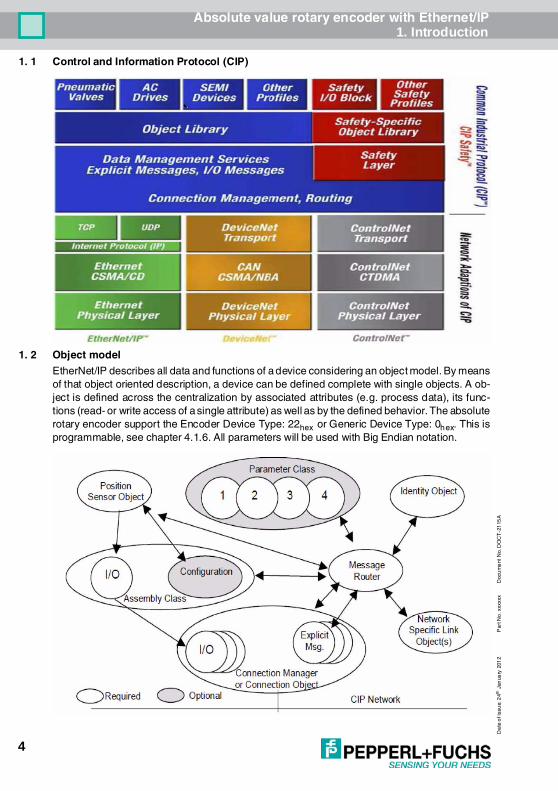
1. 1 Control and Information Protocol (CIP)
1. 2 Object modelEtherNet/IP describes all data and functions of a device considering an object model. By meansof that object oriented description, a device can be defined complete with single objects. A ob-ject is defined across the centralization by associated attributes (e.g. process data), its func-tions (read- or write access of a single attribute) as well as by the defined behavior. The absoluterotary encoder support the Encoder Device Type: 22hex or Generic Device Type: 0hex. This isprogrammable, see chapter 4.1.6. All parameters will be used with Big Endian notation.

Absolute value rotary encoder with Ethernet/IPData Transmission
5
Dat
e o
f is
sue:
24
th J
anu
ary
2012
Pa
rt N
o. x
xxxx
xD
ocu
men
t No.
DO
CT
-211
5
2 Data TransmissionThe data transmission in the EtherNet/IP network is realized by implicit or explicit messaging. Ex-plicit messages are split in unconnected and connection based versions. Unconnected mes-sages will be use i.e. by EtherNet/IP scanners.
2. 1 Implicit Messaging I/O ConnectionProvide dedicated, special-purpose communica-tion paths between a producing application andone or more consuming applications for the purpose of moving application-specific data. This isoften referred to as implicit messaging. Class 0 and 1 are supported.
2.1.1 I/O Assembly InstancesInstance Type Name1 Input Position Value3 Input Position Value and Velocity

Absolute value rotary encoder with Ethernet/IPData Transmission
6
Da
te o
f iss
ue:
24th
Jan
uary
201
2P
art N
o. x
xxxx
xD
ocu
me
nt N
o. D
OC
T-2
115
A
2.1.1.1 Data Attribute Format
2.1.2 Data Mapping
2.1.3 Data Mapping (Parameter)On every Forward Open Request, the following parameters, will be sent from the controller tothe encoder. Assembly Instance Configuration: 7, size 12 Bytes
2.1.3.1 Data Offset
Instance Byte Bit 7 Bit 6 Bit 5 Bit 4 Bit 3 Bit 2 Bit 1 Bit 01 0 Position Value (low Byte)
123 Position Value (high Byte)
3 0 Position Value (low Byte)123 Position Value (high Byte)4 Velocity (low Byte)567 Velocity (high Byte)
Data ComponentName
Class Instance Number
AttributeName Number Name Number
Position Value Position Sensor 23hex 1 Position Value 0AhexVelocity Position Sensor 23hex 1 Velocity 18hex
Configuration ParameterName
Class Instance Number
AttributeName Number Name Number
Direct Counting Toggle Position Sensor 23hex 1 Direct Counting Toggle 0ChexScaling Function Control Position Sensor 23hex 1 Scaling Function Control 0EhexMeasuring units per Revolution Position Sensor 23hex 1 Measuring Units per Span 10hexTotal Measuring Range in measuring units
Position Sensor 23hex 1 Total Measuring Range inmeasuring units
11hex
Velocity Format Position Sensor 23hex 1 Velocity Format 19hex
Byte Offset Bit 7 Bit 6 Bit 5 Bit 4 Bit 3 Bit 2 Bit 1 Bit 00 Direction Counting Toggle1 Scaling Function Control2 Measuring units per Revolution (low byte)345 Measuring units per Revolution (high byte)6 Total Measuring Range in measuring units (low byte)789 Total Measuring Range in measuring units (high byte)10 Velocity Format (low byte)11 Velocity (high byte)

Absolute value rotary encoder with Ethernet/IPData Transmission
7
Dat
e o
f is
sue:
24
th J
anu
ary
2012
Pa
rt N
o. x
xxxx
xD
ocu
men
t No.
DO
CT
-211
5
2.1.4 Connection PathIs made up of a byte stream that defines the application object to which a connection instanceapplies. This path will be created from the configuration tools and are available in the EDS filetoo. This path will sent during power up to the encoder. For some tools it is necessary to use theconnection path as parameter:
2. 2 Explicit MessagingProvide generic, multi-purpose communication paths between two devices. These connectionsoften are referred to as just Messaging Connections. Explicit Messages provide the typical re-quest/response-oriented network communications. Class 2 and 3 are supported.
2.2.1 CIP Common Services
Position Sensor Objects Instance Attributes (Get: read, Set: write + read) Class Code: 23hex
[20] [04] [24 07] [2C 06] [2C 01] [80 06 00 01 00100000 00200000 041F]Segment Groups Segment DescriptionApplication Path 20 04 Assembly object class
24 07 Instance segment type with Assembly Instance 7 (Configuration)2C 06 Assembly Instance 6 (Output controller to encoder)2C 01 I/O Assembly Instance 1 (Position value)80 06 Data segment with lenght of 6 Bytes00 01 00100000 00200000 041F Configuration Data, see chapter 2.1.3.1 for details
Supported Service Code
Service Name Comment
05hex Reset Boot up of the encoder, the programmed parameter from the customer will use again
0Ehex Get_Attribute_Single Read out attribute from the encoder10hex Set_Attribute_Single Write attribute to the encoder15hex Restore Restore the saved parameters16hex Save Save the parameters from chapter 2.1.3 to the nonvolatile memory
Attrib. ID Access Name Data Type Description01hex Get Number of Attributes USINT Number of supported Attributes02hex Get Attribute List Array of USINT List of supported Attribute0Ahex Get Position Value Signed DINT Current position signed0Bhex Get Position Sensor Type UINT Specifies the device type0Chex Set Direction Counting Toggle Boolean Controls the code sequence
clockwise or counterclockwise0Ehex Set Scaling Function Control Boolean Scaling function on/off10hex Set Measuring units per Span UDINT Resolution for one revolution11hex Set Total Measuring Range in
Measuring UnitsUDINT Total resolution
13hex Set Preset Value DINT Setting a defined position value18hex Get Velocity Value DINT Current speed in format of attribute 19hex and 2Ahex19hex Set Velocity Format ENGUINT Format of the velocity attributes29hex Get Operating Status BYTE Encoder diagnostic operating status2Ahex Get Physical Resolution Span UDINT Resolution for one revolution2Bhex Get Number of Spans UINT Number of revolutions33hex Get Offset Value DINT Shift position value with the calculated value64hex Set Device Type DINT Encoder device = 22hex Generic device = 0 (default)65hex Set Endless Shaft DINT Off = 0, On = 1, Auto = 266hex Set Velocity Filter DINT Fine = 0, Middle = 1, Raw = 2
Absolute value rotary encoder with Ethernet/IPData Transmission
8
Da
te o
f iss
ue:
24th
Jan
uary
201
2P
art N
o. x
xxxx
xD
ocu
me
nt N
o. D
OC
T-2
115
A
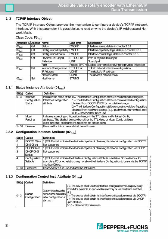
2. 3 TCP/IP Interface ObjectThe TCP/IP Interface Object provides the mechanism to configure a device’s TCP/IP net-workinterface. With this parameter it is possible i.e. to read or write the device’s IP Address and Net-work Mask. Class Code: F5hex
2.3.1 Status Instance Attribute (01hex)
2.3.2 Configuration Instance Attribute (02hex)
2.3.3 Configuration Control Inst. Attribute (04hex)
Attribute ID Access Name Data Type Description01hex Get Status DWORD Interface status, details in chapter 2.3.102hex Get Configuration Capability DWORD Interface capability flags, details in chapter 2.3.203hex Set Configuration Control DWORD Interface control flags, details in chapter 2.3.304hex Get Physical Link Object STRUCT of: Path to physical link object
Path size UINT Size of pathPath Padded EPATH Logical segments identifying the physical link object
05hex Set Interface Configuration STRUCT of: TCP/IP network interface configurationIP Address UDINT The device’s IP addressNetwork Mask UDINT The device’s network mask
06hex Set Host Name STRING
Bit(s) Called Definition0 - 3 Interface
ConfigurationStatus
Indicates the status of theInterface Configurationattribute.
0 = The Interface Configuration attribute has not been configured.1 = The Interface Configuration attribute contains valid configuration obtained from BOOTP, DHCP or nonvolatile storage.2 = The Interface Configuration attribute contains valid configuration, obtained from hardware settings (e.g.: pushwheel, thumbwheel, etc.)3-15 = Reserved for future use.
4 McastPending
Indicates a pending configuration change in the TTL Value and/or Mcast Configattributes. This bit shall be set when either the TTL Value or Mcast Config attributeis set, and shall be cleared the next time the device starts.
5 - 31 Reserved Reserved for future use and shall be set to zero.
Bit(s) Called Definition0 BOOTP Client 1 (TRUE) shall indicate the device is capable of obtaining its network configuration via BOOTP.1 DNS Client Not supported2 DHCP Client 1 (TRUE) shall indicate the device is capable of obtaining its network configuration via DHCP.3 DHCP-DNS
UpdateNot supported
4 Configuration Settable
1 (TRUE) shall indicate the Interface Configuration attribute is settable. Some devices, for example a PC or workstation, may not allow the Interface Configuration to be set via the TCP/IP Interface Object.
5 - 31 Reserved Reserved for future use and shall be set to zero.
Bit(s) Called Definition
0 - 3 Startup Configuration
Determines how the device shall obtain its initial configuration at start up.
0 = The device shall use the interface configuration values previously stored (for example, in non-volatile memory or via hardware switches, etc).1 = The device shall obtain its interface configuration values via BOOTP.2 = The device shall obtain its interface configuration values via DHCP upon start-up.3-15 = Reserved for future use.

Absolute value rotary encoder with Ethernet/IPData Transmission
9
Dat
e o
f is
sue:
24
th J
anu
ary
2012
Pa
rt N
o. x
xxxx
xD
ocu
men
t No.
DO
CT
-211
5
2.3.4 Physical Link Object (05hex)This attribute identifies the object associated with the underlying physical communications inter-face (e.g., an 802.3 interface). There are two components to the attribute: a Path Size (in UINTs)and a Path. The Path shall contain a Logical Segment, type Class, and a Logical Segment, typeInstance that identifies the physical link object. The maximum Path Size is 6 (assuming a 32 bitlogical segment for each of the class and instance).The physical link object itself typically maintains link-specific counters as well as any link specificconfiguration attributes. If the CIP port associated with the TCP/IP Interface Object has an Eth-ernet physical layer, this attribute shall point to an instance of the Ethernet Link Object (classcode = F6hex). When there are multiple physical interfaces that correspond to the TCP/IP inter-face, this attribute shall either contain a Path Size of 0, or shall contain a path to the object rep-resenting an internal communications interface (often used in the case of an embedded switch).For example, the path could be as follows:
2.3.5 Interface Configuration (06hex)
2.3.6 Host Name
2. 4 Ethernet Link ObjectClass Code: F6hex
Path Meaning
0 - 3 [20] = 8 bit class segment type; [F6] = Ethernet Link Object class;[24] = 8 bit instance segment type; [01] = instance 1.
Name MeaningIP Address
The device’s IP address. Value of 0 indicates no IP address has been configured. Otherwise, the IP address shall be set to a valid Class A, B, or C address and shall not be set to the loopback address (127.0.0.1).
Networkmask
The device’s network mask. The network mask is used when the IP network has been partitioned into subnets. The network mask is used to determine whether an IP address is located on another subnet. Value of 0 indi-cates no network mask address has been configured.
Name MeaningHost Name
ASCII characters. Maximum length is 64 characters. Shall be padded to an even number of characters (pad not included in length). A length of 0 shall indicate no Host Name is configured.
Attribute ID Access Name Data Type Description Semantics of Values01hex Get Revision UINT Revision of this object The minimum value shall be 1. Shall be 2
or greater if instance attribute 6 is imple-mented.Shall be 3 if any instance attributes 7-10 are implemented.The maximumvalue shall be 3.
02hex Get Max Instance
UINT Maximum instance number of an object currently created in this class level of the device
The largest instance number of a createdobject at this class hierarchy level
03hex Get Number of Instances
UINT Number of object instances currently created at this class level of the device
The number of objectinstances at this classhierarchy level

Absolute value rotary encoder with Ethernet/IPData Transmission
10
Da
te o
f iss
ue:
24th
Jan
uary
201
2P
art N
o. x
xxxx
xD
ocu
me
nt N
o. D
OC
T-2
115
A
2.4.1 Instance Attributes
2.4.2 Instance Flags
2.4.3 Common Service
ID Access Name Data Type Description of Attribute
Semantics of Values
1 Get Interface Speed UINT Interface speed cur-rently in use
Speed in Mbps (e.g., 10, 100
2 Get Interface Flags DWORD Interface status flags See chapter 2.4.13 Get Physical Address ARRAY of 6
USINTsMAC layer address Displayed format “XX-XX-XXXX-
XX-XX”7 Get Interface Type USINT Type of interface 1 = The interface is internal to the device, i.e. in
the case of an embedded switch2 = Twisted-pair (e.g. 100Base-TX)
8 Get Interface State USINT Current state of the interface
0 = No link1 = The interface is enabled and is ready to send and receive data
10 Get Interface Label SHORT_STRING
Human readable identification
„Internal switch“ or„External Port 1“ or„External Port 2“
Bit(s) Called Definition0 Link Status Indicates whether or not the Ethernet 802.3 communications interface is connected to an active
network. 0 indicates an inactive link; 1 indicates an active link. The determination of link status is implementation specific. In some cases devices can tell whether the link is active via hard-ware/driver support. In other cases, the device may only be able to tell whether the link is active by the presence of incoming packets.
1 Half/Full Duplex
Indicates the duplex mode currently in use. 0 indicates the interface is running half duplex; 1 indicates full duplex. Note that if the Link Status flag is 0, then the value of the Half/Full Duplex flag is indeterminate.
2 - 4 Negotiation Status
Indicates the status of link auto-negotiation0 = Auto-negotiation in progress.1 = Auto-negotiation and speed detection failed. Using default values for speed and duplex. Default values are product-dependent; recommended defaults are 10Mbps and half duplex.2 = Auto negotiation failed but detected speed. Duplex was defaulted.Default value is product-dependent; recommended default is half duplex.3 = Successfully negotiated speed and duplex.4 = Auto-negotiation not attempted. Forced speed and duplex.
5 Manual SettingRequires Reset
0 indicates the interface can activate changes to link parameters (autonegotiate, duplex mode, interface speed) automatically. 1 indicates the device requires a Reset service be issued to its Identity Object in order for the changes to take effect.
6 Local HardwareFault
0 indicates the interface detects no local hardware fault; 1 indicates a local hardware fault is detected. The meaning of this is product-specific. Examples are an AUI/MII interface detects no transceiver attached or a radio modem detects no antennae attached. In contrast to the soft, possible selfcorrecting nature of the Link Status being inactive, this is assumed a hardfault requiring user intervention.
7 Reserved Shall be set to zero
ServiceCode
Class Instance* ServiceName
Description of Service
0Ehex Conditional Required Get_Attribute_Single Returns the contents of the specified attribute10hex n/a Conditional Set_Attribute_Single Modifies a single attribute

Absolute value rotary encoder with Ethernet/IPData Transmission
11
Dat
e o
f is
sue:
24
th J
anu
ary
2012
Pa
rt N
o. x
xxxx
xD
ocu
men
t No.
DO
CT
-211
5
2.4.4 Link Object Instances
2. 5 Setting parameters with scannersThere are several external scanners for EtherNet/IP available. RS-NetWorksTM has one suchscanner. In the figure is an example where the IP-Address (FD 00 A8 C0 complies192.168.0.253) and the Gateway (00 FF FF FF complains 255.255.255.0) was read out of theencoder.
Instance Description1 Internal interface2 Intern switch Port 13 Intern switch Port 2

Absolute value rotary encoder with Ethernet/IPData Transmission
12
Da
te o
f iss
ue:
24th
Jan
uary
201
2P
art N
o. x
xxxx
xD
ocu
me
nt N
o. D
OC
T-2
115
A
In RSNetWorx is a scanner available too. In the next section is a sample to set the Preset value.
2.5.1 Read out position valueGet Single Attribute Position sensor value:Class: 0x23 (Position sensor object)Instance: 0x01Attribute: 0x0A (Position Value)

Absolute value rotary encoder with Ethernet/IPData Transmission
13
Dat
e o
f is
sue:
24
th J
anu
ary
2012
Pa
rt N
o. x
xxxx
xD
ocu
men
t No.
DO
CT
-211
5
2.5.2 Set preset value Set Single Attribute Position Preset Value to 1Class: 0x23 (Position sensor object)Instance: 0x01Attribute: 0x13 (Preset Value)
2.5.3 Get preset valueGet Single Attribute Position ValueClass: 0x23 (Position sensor object)Instance: 0x01Attribute: 0x13 (Preset Value)

Absolute value rotary encoder with Ethernet/IPDiagnostic
14
Da
te o
f iss
ue:
24th
Jan
uary
201
2P
art N
o. x
xxxx
xD
ocu
me
nt N
o. D
OC
T-2
115
A
3 Diagnostic
Table 1: Module Status Indicator Stat1/Stat2
Table 2: Network Status Indicator Stat2
LED Color EtherNet/IP name DescriptionActive1 Yellow Network Status Indicator 1 Details in table 2Link1 GreenActive2 Yellow Network Status Indicator 2 Details in table 2Link2 GreenStat1 Green Module Status Indicator Details in table 1Stat2 Red

Absolute value rotary encoder with Ethernet/IPProgrammable Parameters
15
Dat
e o
f is
sue:
24
th J
anu
ary
2012
Pa
rt N
o. x
xxxx
xD
ocu
men
t No.
DO
CT
-211
5
4 Programmable Parameters4. 1 Encoder parameters for Position Sensor Object Class 23hex
4.1.1 Direction countingThis operating parameter can be used to select the code sequence. The parameter can set withConfiguration Assembly and Explicit Messaging
The parameter code sequence (complement) defines the counting direction of the process valueas seen on the shaft ( clockwise or counter clockwise).The counting direction is defined in the attribute 0Chex:
4.1.2 Scaling function controlIf the Scaling function control is deactivated then complains the output value the physical reso-lution.
If the Scaling function control is deactivated then complains the output value the physical reso-lution.I
This parameter can be set with Configuration Assembly and Explicit Messaging
Attribute ID Default value Value range Data Type0Chex 0hex 0hex - 1hex Boolean
Bit 0 Counting direction Position values0 CW Increase1 CCW Decrease
Attribute ID Default value Value range Data Type0Ehex 1hex 0hex - 1hex Boolean
Bit 0 Scaling function on/off0 on1 off

Absolute value rotary encoder with Ethernet/IPProgrammable Parameters
16
Da
te o
f iss
ue:
24th
Jan
uary
201
2P
art N
o. x
xxxx
xD
ocu
me
nt N
o. D
OC
T-2
115
A
4.1.3 Resolution per revolutionThe parameter resolution per revolution is used to program the encoder to set a desired numberof steps per revolution. Each value between 1 and the maximum (see type label) can be real-ized.The parameter can set with Configuration Assembly and Explicit Messaging.
(*) see type label, Maximum resolution:16 Bit Encoder: 10,000hex (65,536)When the value is set larger than 8192 for a 13Bit encoder, the process value of the encoder willnot be single stepped and values will be skipped while rotating the shaft. So, it is recommended,to keep the measuring steps per revolution below 8192 measuring steps.
4.1.4 Total resolutionThis value is used to program the desired number of measuring steps over the total measuringrange. This value must not exceed the total resolution of the encoder with 25 bit =33,554,432 steps. Please note the value written on the type shield. The parameter can set withConfiguration Assembly and Explicit Messaging
(*) see type shieldMaximum total resolution30 Bit Encoder: 40,000,000hex (1,073,741,824)Attention:The following formula letters will be used:- PGA Physical total resolution of the encoder (see type label)- PAU Physical resolution per revolution (see type label)- GA Total resolution (customer parameter)- AU Resolution per revolution (customer parameter)If the desired resolution per revolution is less than the physical resolution per revolution of theencoder, then the total resolution must be entered as follows:Total resolutionGA = PGA * AU / PAU, if AU < PAUExample: Customer requirement: AU = 2048,Encoder type shield: PGA=25 bit, PAU=13 bitGA = 16777216 * 2048 / 8192GA = 8388608If the total resolution of the encoder is less than the physical total resolution, the parameter totalresolution must be a multiple of the physical total resolution:- k = PGA / GA- k = integer
Attribute ID Default value Value range Data Type10hex (*) 0hex - 10000hex Double Integer32
Attribute ID Default value Value range Data Type11hex (*) 0hex - 40,000,000hex Unsigned Integer 32

Absolute value rotary encoder with Ethernet/IPProgrammable Parameters
17
Dat
e o
f is
sue:
24
th J
anu
ary
2012
Pa
rt N
o. x
xxxx
xD
ocu
men
t No.
DO
CT
-211
5
4.1.5 Preset valueThe preset value is the desired position value, which should be reached at a certain physical po-sition of the axis. The position value of the encoder is set to the desired process value by the pa-rameter preset. The preset value must not exceed the parameter total measuring units. Theparameter can set with Explicit Messaging.Set the preset value only in standstill!
4.1.6 Velocity FormatDefault value for Velocity Format is steps persecond. This parameter can be set with Configura-tion Assembly and Explicit Messaging.
4.1.7 Velocity FilterTo manage the noise of the velocity it is possible to switch between three classes. See the dia-gramms to see the differences.
Diagram 1Diagram 2Diagram 3
4.1.8 Device TypeThe EtherNet/IP interface supports the Encoder Device with device type 22 hex functionality orthe Generic Device type 0hex according to the CIP specification. As all controllers do not supportthe Encoder Device the encoder changed to the Device Type. This parameter can set only withExplicit Messaging.
4.1.9 Endless ShaftNormally the period, i.e. “Total resolution”/“measuring units” per revolution must be an integerand it must fit an integer number of times (integer multiple) into 4096 for an encoder with 12 Bitfor the revolutions. So the following equation must apply:(4096 x measuring units per revolution) / Total resolution = integerBut with this EtherNet/IP encoder it is possible to solve this problem. If the Endless Shaft is acti-vated then this problem will be solved by the encoder. The default value is Auto. In this case theencoder checks if the parameters need the endless shaft. The parameter can be set onlywith Explicit Messaging.
Attribute ID Default value Value range Data Type13hex 0hex 0hex - total measuring range Unsigned Integer 32
Attribute ID Default value Value range Data length19hex 1F04hex 1F04hex Steps per second
1F05hex Steps per millisecond1F06hex Steps per microsecond1F07hex Steps per minute1F0Fhex RPM
Attribute ID Default value Value range Description Data Type66hex 0hex 0hex/1hex/2hex 0 = Fine, 1 = Middle, 2 = Raw Double Integer
Attribute ID Default value Value range Data Type64hex 0hex 0hex/22hex Double Integer

Absolute value rotary encoder with Ethernet/IPInstallation
18
Da
te o
f iss
ue:
24th
Jan
uary
201
2P
art N
o. x
xxxx
xD
ocu
me
nt N
o. D
OC
T-2
115
A
Note: The internal software routine only works if the encoder is in operation. If it is necessary toturn the encoder shaft more than 1024 revolutions without power supply this can lead to prob-lems (the internal routine will not work without power supply). In this case the rule ahead shouldbe observed even with new devices.
5 Installation5. 1 Electrical connection
The rotary encoder is connected by a 4 pin M12 connector for the power supply and two 4 pin,D-coded M12 connector for Ethernet. The Encoder uses a second D-coded connector and pro-vides an integrated switch functionality.On or in the packaging of the connector is the mounting description.
Sketch as seen on the encoder
5. 2 Ethernet cables5.2.1 RJ45 – M12 crossed
5.2.2 RJ45 – M12 straight
Attribute ID Default value Value range Description Data Type65hex 2hex 0hex/1hex/2hex 0 = off, 1 = on, 2 = Auto Double Integer
Connector Ethernet Connector power supply4 pin female, D-coded 4 pin male, A-codedPin Number Signal Pin Number Signal1 Tx+ 1 US (15 - 30 V DC)2 Rx+ 2 n.c.3 Tx- 3 GND (0 V)4 Rx- 4 n.c.
Signal RJ45 Pin M12 Pin SignalTx+ 1 2 Rx+Tx- 2 4 Rx-Rx+ 3 1 Tx+Rx- 6 3 Tx-
Signal RJ45 Pin M12 Pin SignalTx+ 3 1 Tx+Tx- 6 3 Tx-Rx+ 1 2 Rx+Rx- 2 4 Rx-

Absolute value rotary encoder with Ethernet/IPPower On
19
Dat
e o
f is
sue:
24
th J
anu
ary
2012
Pa
rt N
o. x
xxxx
xD
ocu
men
t No.
DO
CT
-211
5
5.2.3 RJ45 – M12 - M12 crossed
6 Power OnAfter power on the LED’s on the absolute rotary encoder will flash between green and red or yel-low.
7 Installation7. 1 Rockwell configuration tools7.1.1 Setting IP-Address (BOOTP/DHCP)
To set the IP Address there are special tools available. I.e. the BOOTP/DHCP Server is installedwith the software package from RSNetWorx™. The server scan the network for the MAC Ad-dresses of all products with active BOOTP or DHCP. If one MAC address is selected in the Re-quest History then the IP Address can be set by the “Add to Relation List” button. The MACAddress of each EtherNet/IP encoder is available on the type label. Note:After a power up the encoder send the BOOTP or DHCP request often. But after several timecomes no answer the frequency of requests decrease. A power up after a longer pause couldsolve the missing requests.If not all encoders are listed in the BOOTP/DHCP Server then check the following points:• LED status of the encoder OK?
• Is the Network setting correct?
• Is the BOOTP and/or DHCP enabled?
If the encoder has got his IP-Address, the BOOTP and DHCP must be disabled with the corre-sponding button. Otherwise the encoder start up to get a new IP-Address again. After setting theIP-Address the Status LED is flashing with 1 Hz. But in this case save the configuration in the Filemenu, because the products cannot be found by the BOOTP/DHCP Server. After loading this filethe MAC Addresses and IP-Addresses are available and BOOTP or DHCP can be activated bythe corresponding button. Possible IP-Range:Class A-C (0.0.0.0 – 223.255.255.255) without Loopback range (127.x.x.x)
Signal M12 Pin M12 Pin SignalTx+ 1 2 Rx+Tx- 3 4 Rx-Rx+ 2 1 Tx+Rx- 4 3 Tx-

Absolute value rotary encoder with Ethernet/IPInstallation
20
Da
te o
f iss
ue:
24th
Jan
uary
201
2P
art N
o. x
xxxx
xD
ocu
me
nt N
o. D
OC
T-2
115
A
Referenced IP-Address range: 192.168.0.x
After setting the IP-Address with this tool the IPAddress will be available only after the nextBOOTP request.
Absolute value rotary encoder with Ethernet/IPInstallation
21
Dat
e o
f is
sue:
24
th J
anu
ary
2012
Pa
rt N
o. x
xxxx
xD
ocu
men
t No.
DO
CT
-211
5
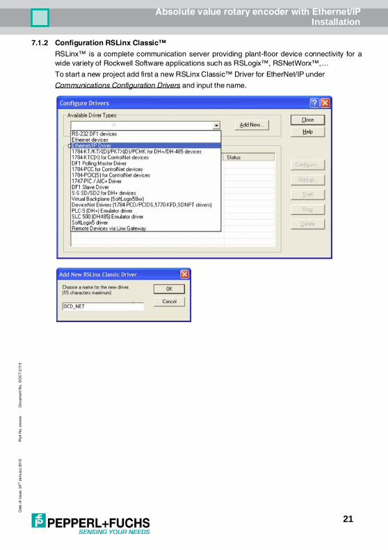
7.1.2 Configuration RSLinx Classic™RSLinx™ is a complete communication server providing plant-floor device connectivity for awide variety of Rockwell Software applications such as RSLogix™, RSNetWorx™,…To start a new project add first a new RSLinx Classic™ Driver for EtherNet/IP under Communications Configuration Drivers and input the name.

Absolute value rotary encoder with Ethernet/IPInstallation
22
Da
te o
f iss
ue:
24th
Jan
uary
201
2P
art N
o. x
xxxx
xD
ocu
me
nt N
o. D
OC
T-2
115
A
Use Browse Local Subnet to find the EtherNet/IP components in the network. The status shouldbe “Running”. Then push the Close button to finish this configuration.
7.1.3 RSNetWorx™RSNetWorx™ products provide design and configuration management services for EtherNet/IP. The program defines and configures the devices on the network quickly througha simple software interface. This definition can take place offline using drag and drop operationsor online by using RSLinx® to browse a EtherNet/IP network.

Absolute value rotary encoder with Ethernet/IPInstallation
23
Dat
e o
f is
sue:
24
th J
anu
ary
2012
Pa
rt N
o. x
xxxx
xD
ocu
men
t No.
DO
CT
-211
5
EDS WizardThe EDS File contains information about device specific parameters as well as possible operat-ing modes of the encoder. With this file you have a data sheet in an electronic format, which canbe used to configure the device in the network, for example with RSNetWorx™ from Rockwell.In this sample the PLC uses address 192.168.0.100 and the encoder 192.100.0.252.To install the EDS file the EDS Wizard has to be started, that can be done in the menu Tools/EDSWizard. If the EDS Wizard is activated successfully the Register an EDS File(s) has to be chosenand after that the button weiter. In the next step the Register a directory of EDS files has to bechosen and with Browse the path of the EDS file(s). That is indicated in the next pictures.

Absolute value rotary encoder with Ethernet/IPInstallation
24
Da
te o
f iss
ue:
24th
Jan
uary
201
2P
art N
o. x
xxxx
xD
ocu
me
nt N
o. D
OC
T-2
115
A
The Wizard finds all EDS files that are discarded in the choosing path and operates a test tocheck the EDS files on errors. In the next step (see picture 1.3) pictures can be selected for theusing nodes. With the button weiter the installation can be continued and finished.

Absolute value rotary encoder with Ethernet/IPInstallation
25
Dat
e o
f is
sue:
24
th J
anu
ary
2012
Pa
rt N
o. x
xxxx
xD
ocu
men
t No.
DO
CT
-211
5
Load a save d *. enet f ile or sta rt a new pr oject. Add t he de vice s per Drag a nd Dro p to t he ne t work line and se t the IP- Ad dress.
Optional browse the network with all devices with Button or Upload from Network. So it is not necessary to set the IP-Address manually.For using this config uratio n in RSLogix sa ve the* .en et file.
Absolute value rotary encoder with Ethernet/IPInstallation
26
Da
te o
f iss
ue:
24th
Jan
uary
201
2P
art N
o. x
xxxx
xD
ocu
me
nt N
o. D
OC
T-2
115
A
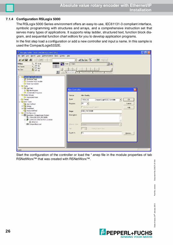
7.1.4 Configuration RSLogix 5000The RSLogix 5000 Series environment offers an easy-to-use, IEC61131-3 compliant interface,symbolic programming with structures and arrays, and a comprehensive instruction set thatserves many types of applications. It supports relay ladder, structured text, function block dia-gram, and sequential function chart editors for you to develop application programs.In the first step load a configuration or add a new controller and input a name. In this sample isused the CompactLogix5332E.
Start the configuration of the controller or load the *.enep file in the module properties of tabRSNetWorx™ that was created with RSNetWorx™.

Absolute value rotary encoder with Ethernet/IPInstallation
27
Dat
e o
f is
sue:
24
th J
anu
ary
2012
Pa
rt N
o. x
xxxx
xD
ocu
men
t No.
DO
CT
-211
5
Absolute value rotary encoder with Ethernet/IPInstallation
28
Da
te o
f iss
ue:
24th
Jan
uary
201
2P
art N
o. x
xxxx
xD
ocu
me
nt N
o. D
OC
T-2
115
A
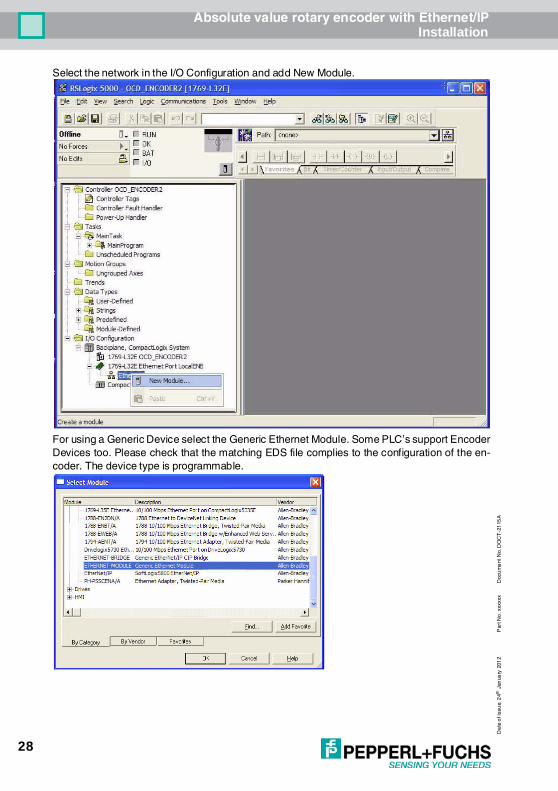
Select the network in the I/O Configuration and add New Module.
For using a Generic Device select the Generic Ethernet Module. Some PLC’s support EncoderDevices too. Please check that the matching EDS file complies to the configuration of the en-coder. The device type is programmable.

Absolute value rotary encoder with Ethernet/IPInstallation
29
Dat
e o
f is
sue:
24
th J
anu
ary
2012
Pa
rt N
o. x
xxxx
xD
ocu
men
t No.
DO
CT
-211
5
Set the Connection Parameters according the following figure.
Set the cycle time.

Absolute value rotary encoder with Ethernet/IPInstallation
30
Da
te o
f iss
ue:
24th
Jan
uary
201
2P
art N
o. x
xxxx
xD
ocu
me
nt N
o. D
OC
T-2
115
A
To read or write data use Logic - Monitor Tags

Absolute value rotary encoder with Ethernet/IPInstallation
31
Dat
e o
f is
sue:
24
th J
anu
ary
2012
Pa
rt N
o. x
xxxx
xD
ocu
men
t No.
DO
CT
-211
5
• If the value is 00 then the standard configuration will be used
• If the Paramter are out of range the maximum value of the encoder will be used as parameter
• To change parameters open Communication Who Active, Go Offline, File Save , select con-troller,
• Download , Run
• These parameter can set by a standard EtherNet/IP scanner tool too.
If everything is running then, in the “Errors tab” the message 0 error(s) should appear.

Absolute value rotary encoder with Ethernet/IPInstallation
32
Da
te o
f iss
ue:
24th
Jan
uary
201
2P
art N
o. x
xxxx
xD
ocu
me
nt N
o. D
OC
T-2
115
A
7. 2 Schneider configuration toolsIn the software tool Unity it is possible to configure the parameters of the encoders. EDS file helpto change the parameters on an easy way. Select the EtherNet/IP module and start the Ether-Net/IP configuration tool.
In the first time it is necessary to install the EDSFile with the wizard.

Absolute value rotary encoder with Ethernet/IPInstallation
33
Dat
e o
f is
sue:
24
th J
anu
ary
2012
Pa
rt N
o. x
xxxx
xD
ocu
men
t No.
DO
CT
-211
5
Select the EDS-File, available on our web side, and follow the wizard to the end.
Select the encoder in the Device Library and Insert in Configuration (menu opens on right buttonclick of the mouse).

Absolute value rotary encoder with Ethernet/IPInstallation
34
Da
te o
f iss
ue:
24th
Jan
uary
201
2P
art N
o. x
xxxx
xD
ocu
me
nt N
o. D
OC
T-2
115
A
Set the IP-Adress of the encoder in the General-Tab. In Tab Connections under ConfigurationSetting is it possible to change the parameters in the offline state. The PLC will send this param-eters to the encoder during the start up phase.
In Tab Online Parameters can be changed or read out all parameters. There can set i.e. the pre-set value. Change all parameters, push the Synchronize button and Send Values to the device.

Absolute value rotary encoder with Ethernet/IPFAQ
35
Dat
e o
f is
sue:
24
th J
anu
ary
2012
Pa
rt N
o. x
xxxx
xD
ocu
men
t No.
DO
CT
-211
5
8 FAQ8. 1 Problem:
IP Address unknown and BOOTP/DHCP deactivatedSolution:Use a Ethernet “sniffer” (i.e. http://www.wireshark.org) or
8. 2 Problem: Replace a rotary encoder in the machine and the controller cannot start the application.Additional the Stat LED is flashing with 2 HzSolution: Start the BOOTP/DHCP server to set the IP-Address. See chapter 7.1
9 GlossarTerm Explanation10Base-T Transmission line with 10 Mbit data transmission rate100Base-T Transmission line with 100 Mbit data transmission rateBaudrate Transmission rate; it display the transmission bits per secondBig Endian Variables will use Byte 0 as Low and last Byte as HighBinary Numeric system with value 0 or 1.BootP A UDP network protocol used by a network client to obtain its IP address automaticallyCAT5 Terminations for transmission rates up to 100 MbitCIP Control and Information ProtocolDHCP Dynamic Host Configuration Protocol is a protocol used by networked devices (clients) to obtain
the parameters necessary for operation in an Internet Protocol network. This protocol reduces sys-tem administration workload, allowing devices to be added to the network with little or no manual configuration.
EIP EtheNet/IPEMC Electromagnetic compatibility, there are rules to verifying devices.ENIP EtherNet/IPEthernet Ethernet is a computer network technology based on frames.Explicit Messages Communication between i.e. a Ethernet scanner and encoderFast Ethernet Transmission technology with 100 Mbit transmission rateFlash Internal memory, saved data will be available after power downImplicit Messaging IO Connection: communication between controller and deviceIP-Address Allow a logic addressing from computer in a networkIP-Protocol The Internet Protocol is widespread in computer networks. It is the implementation of the internet
layer of the TCP/IP-modelMAC Address World wide explicit address of a device.
The encoder use three MAC Adresses: one for internal interface and two for the portsMbit Transmission rate or baud rate, million bits per secondOCD Acronym: OPTOCODE, name of an encoder series manufactured by FRABA POSITALOSI-Model The Open System Interconnection reference model is a open layer model for the organization of a
communication.Scanner Program to send Explicit Messages to the encoderSwitch A switch is an electronic device to connect computers e.g. network segments in a local network.
Unlike a hub, a switch uses stacks to avoid network collisionsTCP The Transmission Control Protocol is a connection orientated transmission protocol, in a network.UDP User Datagram rotocol is utilized to send data that does not need to be transferred in a reliable
way.

Absolute value rotary encoder with Ethernet/IPGlossar
36
Da
te o
f iss
ue:
24th
Jan
uary
201
2P
art N
o. x
xxxx
xD
ocu
me
nt N
o. D
OC
T-2
115
A

Subject to modificationsCopyright PEPPERL+FUCHS • Printed in Germany
www.pepperl-fuchs.com
Worldwide HeadquartersPepperl+Fuchs GmbH68307 Mannheim · GermanyTel. +49 621 776-0E-mail: [email protected]
USA HeadquartersPepperl+Fuchs Inc.Twinsburg, Ohio 44087 · USATel. +1 330 4253555E-mail: [email protected]
Asia Pacific HeadquartersPepperl+Fuchs Pte Ltd.Company Registration No. 199003130ESingapore 139942Tel. +65 67799091E-mail: [email protected]
FACTORY AUTOMATION – SENSING YOUR NEEDS
TDOCT-2115A_ENG xxxxxx01/2012