With a local heritage in working with Stainless Steel, we ...
32
1Pass – a revolutionary Separator that removes 99% of dirt on the first pass of water 10 YEAR WARRANTY BRITISH MADE AND MANUFACTURED
Transcript of With a local heritage in working with Stainless Steel, we ...

www.fabricatedproducts.co.uk | 01709 720 842 | [email protected]
1Pass – a revolutionary Separator that removes 99% of dirt on the first pass of water
10YEAR WARRANTY
BRITISH MADE AND MANUFACTURED

2
www.fabricatedproducts.co.uk | 01709 720 842 | [email protected]
Fabricated Products — Contents
With a local heritage in working with Stainless Steel, we are the first UK manufacturer to offer superior Stainless Steel air and dirt separators.
Our services are utilised by companies within the Water Treatment, Heating & Ventilation Industry throughout the UK, Europe, Scandinavia, the Middle East, Asia and as far as Australia.
Our products are installed worldwide in commercial and industrial applications such as hospitals, schools, universities, M.O.D bases, petro-chemical plants, leisure centres, office blocks etc.
Other aspects of our business include product design and testing, including quality control to British Standards where applicable.
CONTENTS
Fabricated Products — The Solution 3
Product Benefits 4
Electro-Polishing 5
MagVent 5 – 7
1Pass 8 – 9
CleanVent 10 – 12
Pod Insulation System 13
Hydronic Header 14 – 15
Chemical Dosing Pot 16 – 17
EasyTreat 18 – 19
Quick Sticks 20 – 21
Buffer Vessels 22 – 23
Water Expansion Vessels 24
Water Sample Coolers 25
BSP Screwed Dirt Separators 26
BSP Screwed Air Separators 27
Rubber Pump Flexes 28 – 29
Pressure & Temperature Gauges 30
MicroVent 31

3
www.fabricatedproducts.co.uk | 01709 720 842 | [email protected]
Fabricated Products — The Solution Fabricated Products — Contents
We manufacture three ranges of Microbubble Air & Dirt Separators. The CleanVent range, MagVent and 1Pass range for the removal of Air, Dirt, Magnetite and Sludge. We also manufacture Chemical Dosing Pots, Water Sample Coolers, Buffer Vessels and Hydronic Headers.
Modern boilers have very low water content, making them vulnerable to accumulated deposits (dirt) causing boiler failure. The main reason for appliance breakdown is this dirty water. The water that circulates around any heating (or cooling) system will be contaminated with a variety of damaging debris, including magnetite (which turns to sludge).
Such contamination is always damaging to a heating/cooling system, but to the latest generation of high-output, low-water-content appliances, dirty water is a major hazard. System cleansing and water treatment is now vital and necessary to the welfare and prolonged existence of the boiler/chiller plant.
Air Separation & Air and Dirt Separation
Both these units must be installed at the hottest part of the system (before the pumps). In a heating system this is the main flow from the boilers. In a chilled water system the unit must be located in the return close to the chiller.
Dirt Separation Only
This unit should be installed in the return pipework before the flow of water enters any plant (boilers, pumps, etc.). There is no head restriction on this unit. The maximum flow rates through the range of MagVent & CleanVent is 3m/sec. If these values are exceeded the efficiency is reduced.
Commissioning
The CleanVent and MagVent requires no special commissioning. Where fitted, the 3 way valve under the auto air vent valve, should be used when initially filling the system. The same valve is used for draining off floating “scum” that prevents the possibility of dirt clogging the air vent. Maintenance will be required to remove trapped dirt and sludge. This can be done by opening the ball valve at the bottom of the unit. The valve may be opened while the system is under pressure. Scalding is a danger at high pressures and temperatures. Ensure that the water is safely piped to drain before opening the valve. The system pressure will flush the dirt out. Leave the valve open until the collected dirt has been flushed out, repeat this operation every few days. Once the water is clear it may be possible to drain every 6 months or so depending on the size of the system. Most of the dissolved air will be removed in a few days, however, this may vary from system to system. In large systems it may take several weeks. Dirt separators can only remove dirt that is circulating.
Flanges
All flanges are drilled to BS 4504 PN16 as standard. Plain ends and other flange ratings are available on request.
Drain Valve
All models (other than CVA Air Separators) are supplied with a ball valve for draining the collected dirt and sludge.
Installation for the MagVent and CleanVent range

4
www.fabricatedproducts.co.uk | 01709 720 842 | [email protected]
Product BenefitsStainless Steel: Safe, Clean, Efficient and Hygienic
Clear Advantage of Stainless over Carbon Steel
• Extensively more resistant to oxidation by water and biocides, therefore NO contribution to sludge and aeration
• Increased oxygen through aeration causes carbon steel to corrode, however Stainless Steel will NOT corrode
• Smooth Stainless Steel surfaces offer low adhesion of deposits and therefore sludge and magnetite is easily washed and removed 100%
• Stainless Steel is inert in water offering better quality water resulting in minimal bacterial slime, low energy consumption and low cleaning costs
British Design & Manufacture
• Fabricated Products are the first and only company in the UK to design and manufacture these superior products
• Fabricated Products specialise in their manufacture, use and maintenance
• They are manufactured in the heart of the UK with over 100 years‘ heritage working with Stainless Steel
Lighter Weight
• There is approx 40% reduction in the product weight, giving improved handling, easier installation and reduced health and safety issues
• Lighter components can be used which therefore need less structural work
Environmentally Friendly and 100% Recyclable
• The stainless products have hygienic properties which reduce micro bacteria and also have very low bacteria colonisation, ensuring an easy cleaning and environmentally friendly product
• The durability and abrasion resistance mean that the products are effective for long term use and do not cause environmental pollution
• Due to the high value of the stainless materials, the product can be recycled and some of the initial cost can be recovered on recycling
Reduced Lifecycle Costs
• MagVent & CleanVent have a longer life and a resistance to corrosion offering limited degradation in service, there is therefore reduced downtime and little costs required for inspection, maintenance and repair
• There is no requirement for any extra coatings on the product
• MagVent & CleanVent are highly resistant to micro bacteria attacks, they have little likelihood of any deposits adhering to the surface ensuring low cleaning costs
• Their exceptional strength, toughness and impact strength mean they are resistant to stress corrosion, cracking, fatigue and erosion
Reduced Energy Costs
• The smooth surface of the new stainless products reduce friction and requires less energy to pump the water around the system, reducing utility bills
• The thermal properties of the stainless products are far superior allowing them to retain more heat, reducing the need to constantly heat the system
• As the surface of the product is smooth and clean, this keeps an increased and more efficient flow of water
100% British manufactured & designed 10
YEAR WARRANTY

5
www.fabricatedproducts.co.uk | 01709 720 842 | [email protected]
Electro-Polishing
Benefits of Electro-Polishing:
• Aesthetically bright appearance
• Hygienically clean surface
• Maximum corrosion resistance
• Resistance to surface bacterial formation
• Reduces surface roughness by up 50% - makes flushing dirt & sludge easier and gives better results.
• Increase flow rates through the units
Electro-Polishing Superior
Electro-Polishing removes the outer skin of metal along with the embedded contaminants. When the outer skin is dissolved, not only are the embedded contaminants removed, the surface becomes smoother eliminating defects where bacteria can harbour and corrosion can initiate. The end result is the Electro-Polished part is 30 times more corrosion resistant when subjected to salt spray testing. In addition, the surface is much more suited for food, medical and pharmaceutical manufacturing.
Features and Benefits
• High-gauss magnetic rod installed to remove all magnetite in the water system
• Reduced commissioning times after initial fill
• An internal Stainless Steel concentrator to aid removal of air and dirt
• Smooth surfaces with Stainless Steel lead to lower friction
• Stainless Steel will not degrade in service thanks to its excellent resistance to corrosion
• Stainless Steel is extensively more resistant to oxidation by water and biocides than carbon steel, therefore Stainless Steels are not contributing to oxidation sludges
The MagVent range has been developed by Fabricated Products (UK) to remove potentially damaging particles from both hot and chilled water systems. It is comprised of a very fine Stainless Steel strainer capable of stopping debris down to 5 micron. Inside the body of our unit is also a high-gauss magnetic rod, these two elements combined together provide a very powerful cleaning device.
As the water flows through the unit the magnetite is attracted to the magnetic rod and even the smallest particles down to 5 micron are collected. Through simple and cost effective maintenance the magnetic rod is then removed. All magnetite which flows through the unit will be removed 100%.
Electro-Polishing forms a protective layer on both the inside and outside surfaces. Unlike paint which is on top of the steel, Electro-Polishing converts the surface ‘skin’ of the steel into a smooth, corrosion resistant, stain resistant surface which resists corrosion even when scratched or damaged. Also, the smooth internal surfaces allow better flushing of dirt and sludge in your system.

6
www.fabricatedproducts.co.uk | 01709 720 842 | [email protected]
High capacity auto air vent
3-Way Valve / Bleed Valve
Drain Valve
Removable high gauss magnetic rod
1
2
3
4
High capacity auto air vent
3-Way Valve / Bleed Valve
Drain Valve
Removable high gauss magnetic rod
1
2
3
4
Model No: MAGCVAD-RMagVent Combined Air (de-aerator) & Dirt Separator — demountable, removable
MAGCVAD-R50 50 430 338 170 25 380 718 21 Bar
MAGCVAD-R65 65 430 338 170 25 380 718 21 Bar
MAGCVAD-R80 80 490 408 220 25 440 848 21 Bar
MAGCVAD-R100 100 490 408 220 25 440 848 21 Bar
MAGCVAD-R125 125 630 518 325 25 550 1068 21 Bar
MAGCVAD-R150 150 630 518 325 25 550 1068 21 Bar
MAGCVAD-R200 200 810 615 410 50 650 1265 21 Bar
MAGCVAD-R250 250 880 845 510 50 775 1620 21 Bar
MAGCVAD-R300 300 1100 945 610 50 875 1820 21 Bar
MAGCVAD-R350 350 1500 1020 770 50 950 1970 21 Bar
MAGCVAD-R400 400 1500 1195 770 50 1125 2320 21 Bar
MAGCVAD-R450 450 1750 1195 920 50 1125 2320 21 Bar
Model No. A B C D E F G Tested to
Dimensions (mm)1
24
B
E
D
F
C
G
A
3
MagVent Combined Air (de-aerator) & Dirt Separator
MAGCVAD-50 50 430 300 170 25 380 680 21 Bar
MAGCVAD-65 65 430 300 170 25 380 680 21 Bar
MAGCVAD-80 80 490 360 220 25 440 800 21 Bar
MAGCVAD-100 100 490 360 220 25 440 800 21 Bar
MAGCVAD-125 125 630 470 325 25 550 1020 21 Bar
MAGCVAD-150 150 630 470 325 25 550 1020 21 Bar
MAGCVAD-200 200 810 555 410 50 640 1195 21 Bar
MAGCVAD-250 250 880 775 510 50 775 1550 21 Bar
MAGCVAD-300 300 1100 875 610 50 875 1750 21 Bar
MAGCVAD-350 350 1500 950 770 50 950 1900 21 Bar
MAGCVAD-400 400 1500 1125 770 50 1125 2250 21 Bar
MAGCVAD-450 450 1750 1125 920 50 1125 2250 21 Bar
MAGCVAD-500 500 2000 1175 1220 50 1175 2350 21 Bar
MAGCVAD-600 600 2000 1325 1220 50 1325 2650 21 Bar
Model No. A B C D E F
Dimensions (mm)
Model No: MAGCVAD
G Tested to
1
2
E
D
F
C
G
A
3
4
B

7
www.fabricatedproducts.co.uk | 01709 720 842 | [email protected]
1 Bleed Valve
Drain Valve
Removable high gauss magnetic rod
2
3
Model No: MAGCVDMagVent Dirt Separator
MAGCVD-50 50 430 310 170 25 114 424 21 Bar
MAGCVD-65 65 430 304 170 25 120 424 21 Bar
MAGCVD-80 80 490 379 220 25 141 520 21 Bar
MAGCVD-100 100 490 366 220 25 154 520 21 Bar
MAGCVD-125 125 630 505 325 25 193 698 21 Bar
MAGCVD-150 150 630 491 325 25 207 698 21 Bar
MAGCVD-200 200 810 590 410 50 290 880 21 Bar
MAGCVD-250 250 880 835 510 50 303 1138 21 Bar
MAGCVD-300 300 1100 947 610 50 353 1300 21 Bar
MAGCVD-350 350 1500 1025 770 50 406 1431 21 Bar
MAGCVD-400 400 1500 1262 770 50 432 1694 21 Bar
MAGCVD-450 450 1750 1218 920 50 495 1713 21 Bar
Model No. A B C D E F G Tested to
Dimensions (mm)B
D
C
F
G
A
2
3
1
E
Bleed Valve
Drain Valve
Removable high gauss magnetic rod
1
2
3
Model No: MAGCVD-RMagVent Dirt Separator — demountable, removable
MAGCVD-R50 50 430 348 170 25 114 462 21 Bar
MAGCVD-R65 65 430 342 170 25 120 462 21 Bar
MAGCVD-R80 80 490 427 220 25 141 568 21 Bar
MAGCVD-R100 100 490 414 220 25 154 568 21 Bar
MAGCVD-R125 125 630 553 325 25 193 746 21 Bar
MAGCVD-R150 150 630 539 325 25 207 746 21 Bar
MAGCVD-R200 200 810 655 410 50 290 945 21 Bar
MAGCVD-R250 250 880 905 510 50 303 1208 21 Bar
MAGCVD-R300 300 1100 1017 610 50 353 1370 21 Bar
MAGCVD-R350 350 1500 1095 770 50 406 1501 21 Bar
MAGCVD-R400 400 1500 1332 770 50 432 1764 21 Bar
MAGCVD-R450 450 1750 1288 920 50 495 1783 21 Bar
Model No. A B C D E F G Tested to
Dimensions (mm)
B
E
D
F
C
G
A
2
3
1

8
www.fabricatedproducts.co.uk | 01709 720 842 | [email protected]
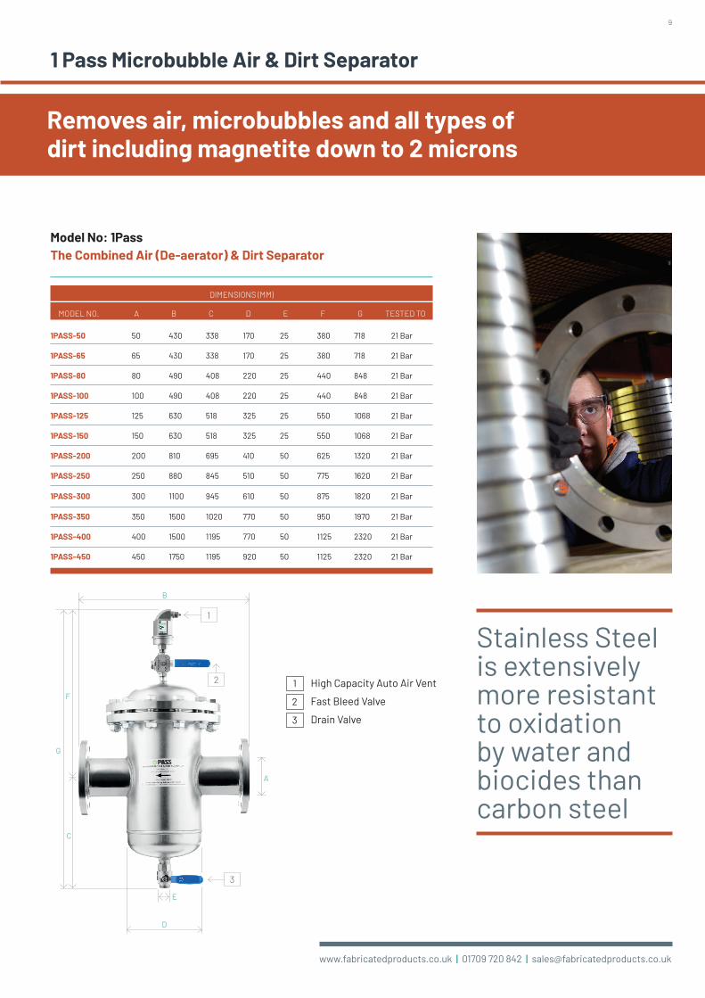
1 Pass Microbubble Air & Dirt Separator
Features and Benefits
• Removes air, microbubbles and all types of dirt including magnetite down to 2 microns
• Greatly reduced commissioning times after initial fill
• Removes 99% of all types of dirt including magnetite on the first pass through the unit
• Longer system life
• Cleans and deaerates the system quicker
• Low-pressure drop
• One directional flow
• Water flows in one side and comes out clean and deaerated the other
• Removes microbubbles at 6 bar in heating systems and 4 bar in chilled water
• Maximum temperature 110°C
• Higher temperature units available on request
• Tested to 21 bar
• All Stainless Steel vessel
The Solution
The 1Pass combines the removal of air and dirt through a single unit. Installed at the hottest point in the system the 1Pass will eliminate these microbubbles from heating and chilled water systems.
The special design of the filter ensures all dirt, including magnetite down to 2 micron, is removed.
All magnetite and any other debris will be removed very quickly, ensuring the time the dirt remains in the water system concerned is at a minimum.
Removes 99%of dirt in just1 pass of the unit
The removal of air and dirt through a single unit
9
www.fabricatedproducts.co.uk | 01709 720 842 | [email protected]
1 Pass Microbubble Air & Dirt Separator
High Capacity Auto Air Vent
Fast Bleed Valve
Drain Valve
1
2
3
Model No: 1PassThe Combined Air (De-aerator) & Dirt Separator
1PASS-50 50 430 338 170 25 380 718 21 Bar
1PASS-65 65 430 338 170 25 380 718 21 Bar
1PASS-80 80 490 408 220 25 440 848 21 Bar
1PASS-100 100 490 408 220 25 440 848 21 Bar
1PASS-125 125 630 518 325 25 550 1068 21 Bar
1PASS-150 150 630 518 325 25 550 1068 21 Bar
1PASS-200 200 810 695 410 50 625 1320 21 Bar
1PASS-250 250 880 845 510 50 775 1620 21 Bar
1PASS-300 300 1100 945 610 50 875 1820 21 Bar
1PASS-350 350 1500 1020 770 50 950 1970 21 Bar
1PASS-400 400 1500 1195 770 50 1125 2320 21 Bar
1PASS-450 450 1750 1195 920 50 1125 2320 21 Bar
MODEL NO. A B C D E F G TESTED TO
DIMENSIONS (MM)
Removes air, microbubbles and all types of dirt including magnetite down to 2 microns
Stainless Steel is extensively more resistant to oxidation by water and biocides than carbon steel
B
E
D
F
C
G
3
1
2
A

10
www.fabricatedproducts.co.uk | 01709 720 842 | [email protected]
1
2
B
E
D
F
C
G
A
3
CVAD-50 50 430 300 170 25 380 680 21 Bar
CVAD-65 65 430 300 170 25 380 680 21 Bar
CVAD-80 80 490 360 220 25 440 800 21 Bar
CVAD-100 100 490 360 220 25 440 800 21 Bar
CVAD-125 125 630 470 325 25 550 1020 21 Bar
CVAD-150 150 630 470 325 25 550 1020 21 Bar
CVAD-200 200 810 555 410 50 640 1195 21 Bar
CVAD-250 250 880 775 510 50 775 1550 21 Bar
CVAD-300 300 1100 875 610 50 875 1750 21 Bar
CVAD-350 350 1500 950 770 50 950 1900 21 Bar
CVAD-400 400 1500 1125 770 50 1125 2250 21 Bar
CVAD-450 450 1750 1125 920 50 1125 2250 21 Bar
CVAD-500 500 2000 1175 1220 50 1175 2350 21 Bar
CVAD-600 600 2000 1325 1220 50 1325 2650 21 Bar
Model No. A B C D E F
Dimensions (mm)
Model No: CVADCombined unit Air (de-aerator) & Dirt Separator
G Tested to
High capacity auto air vent
Fast bleed Valve
Drain Valve
1
2
3
Stainless Steel Air, Microbubbles & Dirt Separation for the Heating & Ventilation Industry.
The CleanVent range has been developed by Fabricated Products (UK) to remove potentially damaging particles from both hot and chilled water systems. It is comprised of a very fine Stainless Steel strainer capable of stopping debris down to 5 micron.
Features and Benefits
• Reduced commissioning times after initial fill
• Can be flushed while fully operational (no need to shut down)
• An internal Stainless Steel concentrator to aid removal of air and dirt
• Smooth surfaces with Stainless Steel lead to lower friction
• Stainless Steel will not degrade in service thanks to its excellent resistance to corrosion
• Stainless Steel is extensively more resistant to oxidation by water and biocides than carbon steel, therefore Stainless Steels are not contributing to oxidation sludges
• Our Stainless Steel separators are up to 40% lighter reducing the need for extra supports around the products in the plant room

11
www.fabricatedproducts.co.uk | 01709 720 842 | [email protected]
CVA-50 50 430 114 170 25 390 504 21 Bar
CVA-65 65 430 120 170 25 384 504 21 Bar
CVA-80 80 490 141 220 25 459 600 21 Bar
CVA-100 100 490 154 220 25 446 600 21 Bar
CVA-125 125 630 193 325 25 585 778 21 Bar
CVA-150 150 630 207 325 25 571 778 21 Bar
CVA-200 200 810 295 410 50 665 960 21 Bar
CVA-250 250 880 303 510 50 835 1138 21 Bar
CVA-300 300 1100 353 610 50 947 1300 21 Bar
CVA-350 350 1500 406 770 50 1025 1431 21 Bar
CVA-400 400 1500 432 770 50 1262 1694 21 Bar
CVA-450 450 1750 495 920 50 1218 1713 21 Bar
CVA-500 500 2000 595 1220 50 1230 1825 21 Bar
D F G Tested to
Model No: CVAD-RRemovable (de-mountable) unit Air & Dirt Separator
CVAD-R50 50 430 338 170 25 380 718 21 Bar
CVAD-R65 65 430 338 170 25 380 718 21 Bar
CVAD-R80 80 490 408 220 25 440 848 21 Bar
CVAD-R100 100 490 408 220 25 440 848 21 Bar
CVAD-R125 125 630 518 325 25 550 1068 21 Bar
CVAD-R150 150 630 518 325 25 550 1068 21 Bar
CVAD-R200 200 810 615 410 50 650 1265 21 Bar
CVAD-R250 250 880 845 510 50 775 1620 21 Bar
CVAD-R300 300 1100 945 610 50 875 1820 21 Bar
CVAD-R350 350 1500 1020 770 50 950 1970 21 Bar
CVAD-R400 400 1500 1195 770 50 1125 2320 21 Bar
CVAD-R450 450 1750 1195 920 50 1125 2320 21 Bar
Model No. A B C D E F G Tested to
Dimensions (mm)
1
2
B
E
D
F
C
G
A
3
1
2
B
D
F
C
G
A
High capacity auto air vent
Fast bleed Valve
1
2
High capacity auto air vent
Fast bleed Valve
Drain Valve
1
2
3
Model No: CVAAir Separator (de-aerator)
Model No. A B C D E F G tested to
Dimensions (mm)
E

12
www.fabricatedproducts.co.uk | 01709 720 842 | [email protected]
Bleed Valve
Drain Valve
1
2
Bleed Valve
Drain Valve
1
2
B
E
D
F
C
G
A
2
1
Model No: CVD-RDirt Separator - demountable, removable
CVD-R50 50 430 348 170 25 114 462 21 Bar
CVD-R65 65 430 342 170 25 120 462 21 Bar
CVD-R80 80 490 427 220 25 141 568 21 Bar
CVD-R100 100 490 414 220 25 154 568 21 Bar
CVD-R125 125 630 553 325 25 193 746 21 Bar
CVD-R150 150 630 539 325 25 207 746 21 Bar
CVD-R200 200 810 655 410 50 290 945 21 Bar
CVD-R250 250 880 905 510 50 303 1208 21 Bar
CVD-R300 300 1100 1017 610 50 353 1370 21 Bar
CVD-R350 350 1500 1095 770 50 406 1501 21 Bar
CVD-R400 400 1500 1332 770 50 432 1764 21 Bar
CVD-R450 450 1750 1288 920 50 495 1783 21 Bar
Model No. A B C D E F G Tested to
Dimensions (mm)
B
E
D
F
C
G
A
2
1
Model No: CVDDirt Separator
CVD-50 50 430 310 170 25 114 424 21 Bar
CVD-65 65 430 304 170 25 120 424 21 Bar
CVD-80 80 490 379 220 25 141 520 21 Bar
CVD-100 100 490 366 220 25 154 520 21 Bar
CVD-125 125 630 505 325 25 193 698 21 Bar
CVD-150 150 630 491 325 25 207 698 21 Bar
CVD-200 200 810 590 410 50 290 880 21 Bar
CVD-250 250 880 791 510 50 347 1138 21 Bar
CVD-300 300 1100 902 610 50 398 1300 21 Bar
CVD-350 350 1500 983 770 50 448 1431 21 Bar
CVD-400 400 1500 1221 770 50 473 1694 21 Bar
CVD-450 450 1750 1174 920 50 539 1713 21 Bar
CVD-500 500 2000 1186 1220 50 639 1825 21 Bar
Model No. A B C D E F G Tested to
Dimensions (mm)

13
www.fabricatedproducts.co.uk | 01709 720 842 | [email protected]
Pod Insulation System
Our new innovative Pod Insulation System allows our low conductivity Stainless Steel units to be even more environmentally friendly. The thermal efficiency properties experienced from this insulation allow your systems to remain working at their optimum level.
The insulation, which is coated in Ventureclad 1577CW foil conforms to all relevant fire and thermal properties making absolutely sure your separators are protected from the atmosphere and do not leak any energy.
Our insulation is manufactured and moulded around our own very unique Stainless Steel separators.
Remove the Velcro straps holding the jacket together
Put both halves carefully around the separator
Use the 16mm Velcro straps provided to wrap around the insulation and pull tight to fit
Pod Insulation System
POD-50/65 170
POD-80/100 220
POD-125/150 325
Model No. D
Dimensions (mm)
Features and Benefits
• Insulation Thickness 20mm thick moulded Polyisocyanurate Foam
• Operating Temperature -10°c to +120°c
• Thermal Conductivity 0.023W/MK
• Typical Density 50–60 KG/m3
• Fire Properties BS476 Part 7, 1971 Class 1, Surface spread of flame, BS476 Part 5 1979, Ignitability Class P
• Moisture Vapour Transmission 38°c 88% Relative humidity (cut Surface) – 1.6 Perms/2"
• External Applications Our Insulation Pods can be installed inside and outside as they are coated with Ventureclad 1577CW to protect against the elements inside and outside
Moulded PR Foam 80kg/m3 density
Insulated box with pipe collars
Ventureclad Outer
D
Fitting of the InsulationThe insulation cover is moulded around our own units so they fit perfectly and there is no need for any modifications on site.

14
www.fabricatedproducts.co.uk | 01709 720 842 | [email protected]
Safety
A well balanced hydraulic water system is highly important for HVAC and process systems with separated circuits or several groups and pumps. The successful removal of air and dirt also contributes towards the achievement of optimum system performance. Hydraulic balancing and air & dirt separation are combined in the Hydronic Header.
Magnetic Low Velocity/Loss Headers are an extended development from Magnetic Microbubble Air & Dirt Separators. The use of LV/LH’s has developed as the norm to be specified in particular with condensing boilers and boilers of low water content where magnetite and sludge particles can easily damage the system.
Some Hydronic Headers end up being manufactured on site. Whilst this doesn’t make them totally ineffective, it means that they will not have the vital factory produced internal membranes which allow microbubbles to rise to the top and magnetite and dirt to fall to the bottom.
Features and Benefits
• All Stainless Steel construction
• The Hydronic Header can be used for both new build projects and for renovating heating, cooling and process systems
• Trapped dirt can be discharged while the system is in operation
• The Hydronic Header is suitable for water and water/glycol mixtures (max. 50%)
• The standard Hydronic Header is suitable for a temperature range of 0 to 110ºC and for an operating pressure of 0 to 10 bar. The flange connection is PN 16
• Other sizes, materials, pressures and temperatures are available on request
• Custom-made solutions and OEM applications
• Fabricated Products offers not only standard products. If required, we work with customers to produce custom-made solutions. These are based on users’ specific requirements. If considered necessary, these can also be supplied as OEM products
• Also available with removable base
Low Velocity / Loss Headers with Magnetic options
Stainless Steel Air and Dirt Separation offers ultimate stability
British Made & Manufactured
Hydronic Balancing is the process of optimising the distribution of water in a building’s heating or cooling system. It provides the intended indoor climate at optimum energy efficiency and minimal operating cost.
Hydronic Header
Now available in both models

15
www.fabricatedproducts.co.uk | 01709 720 842 | [email protected]
1
2
All Magnetite which flows through the unit will be removed 100%
Hydronic Header
The automatic air eliminator at the top plus a quick bleed valve
The 1" BSP drain valve at the base for periodic flushing of sludge
C
D
B
A
G
F
E
HY-CVAD — Hydraulic Air and Dirt Separator
HY-MAGCVAD — Hydraulic Air and Dirt Separator with Magnetic Rod
HY-CVAD-50 50 415 250 295 430 165 960 25 1.4-4.2
HY-CVAD-65 65 425 310 310 430 165 1045 25 2.8-4.7
HY-CVAD-80 80 440 370 320 490 220 1130 25 4.2-8.3
HY-CVAD-100 100 540 470 425 490 220 1435 25 6.9-15.3
HY-CVAD-125 125 605 570 500 630 324 1675 25 9.7-22.2
HY-CVAD-150 150 685 680 565 630 324 1930 25 15.3-33.3
HY-CVAD-200 200 845 880 765 810 406 2490 50 25-55.6
HY-CVAD-250 250 940 1100 860 880 508 2900 50 30.6-97.2
HY-CVAD-300 300 1090 1300 1010 1110 610 3400 50 41.7-138.9
HY-MAGCVAD-50 50 415 250 295 430 165 960 25 1.4-4.2
HY-MAGCVAD-65 65 425 310 310 430 165 1045 25 2.8-4.7
HY-MAGCVAD-80 80 440 370 320 490 220 1130 25 4.2-8.3
HY-MAGCVAD-100 100 540 470 425 490 220 1435 25 6.9-15.3
HY-MAGCVAD-125 125 605 570 500 630 324 1675 25 9.7-22.2
HY-MAGCVAD-150 150 685 680 565 630 324 1930 25 15.3-33.3
HY-MAGCVAD-200 200 845 880 765 810 406 2490 50 25-55.6
HY-MAGCVAD-250 250 940 1100 860 880 508 2900 50 30.6-97.2
HY-MAGCVAD-300 300 1090 1300 1010 1110 610 3400 50 41.7-138.9
model No
model No
A
A
B
B
C
C
D
D
E
E
F
F
G
G
Primary Flow L/Sec
Primary Flow L/Sec
Drainmm
Drainmm
Dimensions (mm)
Dimensions (mm)
1
2
An option with a de-mountable base is also available – see website for detailsRemovable option available upon request.

16
www.fabricatedproducts.co.uk | 01709 720 842 | [email protected]
High Pressure Dosing Pot
Specification
• All Stainless Steel
• Welded to BS EN 287
• All dosing pots that are designed to PD 5500:2018 category 3 (C E marked) have the following max working pressures:
• 14 bar-3.5 litres to 6 litres inclusive
• 10 bar-10 litre to 20 litres inclusive
• 8 bar-25 litres
• 25mm valve size connection
Dosing pots are required in order to feed liquid chemicals such as corrosion inhibitors into closed systems
Chemical Dosing Pot
DP 3.5 3.5 265 275 730 165 76 14 bar
DP 5 5 265 355 810 165 100 14 bar
DP 6 6 265 395 860 165 155 14 bar
DP 10 10 320 395 865 220 155 10 bar
DP 11 11 320 395 865 220 155 10 bar
DP 13.5 13.5 320 490 920 220 227 10 bar
DP 15 15 320 570 1022 220 295 10 bar
DP 16 16 320 570 1022 220 295 10 bar
DP 18 18 320 685 1142 220 430 10 bar
DP 20 20 320 685 1142 220 430 10 bar
DP 25 25 377 585 1040 275 233 25 bar
Product Code
Size (ltrs) A B C D E Max Working Pressure
Dimensions (mm)
A
D
C
B
1" Valves4 off
Air Vent
11mm Ø Holes4 off
Valve D
Valve C
Valve A
Valve B

17
www.fabricatedproducts.co.uk | 01709 720 842 | [email protected]
High Pressure Dosing Pot
Operation
• Isolate pot: close all valves
• Drain pot: open valves A and D
• Charge pot: close valve D and introduce solution via valve A (Tundish)
• Expel air: open air vent until solution appears
• Inject treatment: close valve A fully and open valves B and C
• The dosing pot may reach temperatures up to 110 degrees Celsius
• Protection or warnings should be applied to ensure that personnel do not come into contact with the pot so as to avoid burns
• A check valve is installed to prevent accidental scolding and chemical saturation (blow back) of personnel operating the dosing pot
Installation
It is important that the dosing pots are fitted correctly in to the system to allow rapid chemical feed. This is best achieved by connecting across the main flow and return pipe work. Ideally the flow connection should be made on to the bottom of the dosing pot (valve C), and the return on the top (valve B).
The dosing pot is designed for the conditions stated on the name plate, the system into which the dosing pot is installed should have adequate protection to ensure the dosing pot is operated within these limits at all times.
Specification
• Stainless Steel Shell
• Valve size 25mm BSP female for all dosing pots
• Welded to BS EN 287
• All dosing pots have a max working pressure of 25 bar
• All dosing pots have a max working temperature of 110 degrees Celsius
• Electropolished Stainless Steel finish
Chemical Dosing Pot
3.5 SS.DP3.5-HP 860 170 105 400 300 160 168 25 Bar
5 SS.DP5-HP 940 250 105 400 380 160 168 25 Bar
6 SS.DP6-HP 990 300 105 400 430 160 168 25 Bar
10 SS.DP10-HP 920 200 105 400 360 160 219 25 Bar
11 SS.DP11-HP 920 200 105 400 360 160 219 25 Bar
13.5 SS.DP13.5-HP 1000 280 105 400 440 160 219 25 Bar
15 SS.DP15-HP 1080 360 105 400 520 160 219 25 Bar
16 SS.DP16-HP 1080 360 105 400 520 160 219 25 Bar
18 SS.DP18-HP 1200 480 105 400 640 160 219 25 Bar
20 SS.DP20-HP 1200 480 105 400 640 160 219 25 Bar
25 SS.DP25-HP 982 210 105 400 422 160 324 25 Bar
30 SS.DP30-HP 1052 280 105 400 492 160 324 25 Bar
50 SS.DP50-HP 1332 560 105 400 772 160 324 25 Bar
Size in Litres
Product Code A B C D E F G Max
Pressure
Dimensions (mm)
C
G
Ø25
Valve D
Valve C
Ø25
D
E
A
B
F
Valve AValve B

18
www.fabricatedproducts.co.uk | 01709 720 842 | [email protected]
EasyTreat Dosing Pots
The EasyTreat chemical dosing pots are used for engineered projects. Fully supported by engineering specifications, they offer features and performance unmatched in the industry including high pressure ratings and high temperature ratings.
Features and Benefits
• Closure lid – is easy to open, is inherently safe and the lid is securely restrained
• The fill opening is a full 116mm in diameter, adding chemical products with ease
• All EasyTreat chemical dosing pots are manufactured out of Stainless Steel
• Unique design of the filter/basket to enable slow release of chemicals
• All EasyTreat chemical dosing pots are rated at 16 bar at 200 degrees Celsius
• All EasyTreat chemical dosing pots come complete with Stainless Steel basket
• The short time required to install and use an EasyTreat is unmatched in the industry
• One dose/application from solid chemicals per water system
• All manufactured in the UK
• The EasyTreat can be used for liquid chemicals as well as solid chemicals in heating or cooling systems
With the Quick Sticks, chemicals are provided as solid concentrations in 450g sticks rather than liquid in drums. The solid concentrates are dissolved as needed inside the EasyTreat dosing pot. The chemical solution is then circulated into the system in the same way as liquid chemicals.
The full installation and application costs of chemicals are far cheaper than liquids.
The EasyTreat chemical dosing pot is an innovative water treatment solution for Heating & Cooling water systems that provides the results of high-performance liquid treatment programs, yet is easier to use and is more environmentally responsible.

19
www.fabricatedproducts.co.uk | 01709 720 842 | [email protected]
EasyTreat Dosing PotsEasyTreat Dosing Pots
E
H
J
B
A
J
F
D
GC
I
The EasyTreat allows you to apply chemicals to the water system - whereas with the old style dosing pots, the tundish is often more difficult to reach and much higher off the floor leading to health and safety concerns.
Product EasyTreat 10 EasyTreat 20
Product code ET10 ET20Centre bottom connection to floor A 175 175
CENTRE TO CENTRE CONNECTIONS B 428 628
SPACE FOR CHEMICAL ADDITION C 500 500
DIAMETER OF MAIN BODY D 220 220
O.D. OF BASE PLATE E 320 320
STAINLESS FILTER DIAMETER F 160 160
LENGTH 1" WELD NIPPLE G 50 50
OVERALL HEIGHT H 713 913
1/2" SOCKET I 1/2" Socket 1/2" Socket
1" BSP MALE THREAD J 1" BSP male thread 1" BSP male thread
WEIGHT (KG) 25 28
VOLUME (LTR) 15 25
A view of inside the EasyTreat with a Quick Sticks
Each Quick Stick treats approximately 500 litres of water. Example a 5,000 litre water system will require 10 Quick Sticks.
Much Easier, Much Safer and Less Complicated

20
www.fabricatedproducts.co.uk | 01709 720 842 | [email protected]
Quick Sticks Inhibitors
With the Quick Sticks, chemicals are provided as solid concentrations in 450g sticks rather than liquid in drums. The solid concentrates are dissolved as needed inside the EasyTreat dosing pot. The chemical solution is then circulated into the system being treated in the same way as liquid chemicals.
Simple, Effective and Environmentally Responsible Water Treatment
The Quick Sticks System is a next generation water treatment solution for Heating & Cooling systems that provides key benefits against liquid treatment programs:
• Eliminates drum handling, storage, and disposal
• Reduces splash and spill concerns
• More environmentally friendly
• Proven good results
• No more waste water, draining off to empty before adding more liquid chemicals
Quick Sticks
Quick Sticks Chemical Testing Kit
Quick Sticks Inhibitors are an innovative water treatment solution for Heating & Cooling water systems that provides the results of high-performance liquid treatment programs, yet are easier to use and are more environmentally responsible.
More Environmentally Responsible
Quick Sticks were developed to address the safety and environmental concerns associated with liquid chemicals and offer several benefits associated with green business.
• Maximise energy and water efficiency, therefore helping conserve these precious natural resources and reducing carbon footprint
• Reduced packaging requirements and landfill waste
• Reduced weight, therefore less energy and greenhouse emissions associated with product delivery
• Eco friendly formulae: less hazardous to use, more degradable after discharge and with lower usage requirements
• Minimise waste: 100% consumption of chemical at the point of use; no drum rinsing required
• Eliminates drum disposal concerns

21
www.fabricatedproducts.co.uk | 01709 720 842 | [email protected]
Quick Sticks Inhibitors
Simple and Efficient, Very Cost Effective
• Solid products contain the same high performance actives as liquid formulae, without the water. The solid system has been proven effective in heating & cooling water systems
• Operator only handles a single 0.45kg piece instead of a 25kg or 200kg liquid drum.
• Ideal for use in hard to reach places, such as basements and roof tops
• EasyTreat is specially designed for one application of solid chemicals, not repeated (time consuming) liquid dosing in the inferior tundish type dosing pots
• It’s that simple the HVAC installer can add the Quick Sticks chemicals
Reduce Hazards and Risks / Liabilities
• Innovative manufacturing process reduces the hazards associated with liquids
• No manual handling issues as no heavy drums to move around. Typically one case of Quick Sticks weighs 20kg and contains the same amount of active product as a 200lt drum (227kg weight)
• Reduced chemical exposure: product is fully encapsulated in a water soluble film. The dissolution and feed of the product is fully contained in the Solid System
• Cleaner and cheaper chemical workstation and storage area (no chemical containment required)
• No spills, no mess, no special tools
The benefits of a Solid System include:
Identify system materials of construction/heat exchanger
Contains Aluminium Contains no Aluminium
Quick Sticks 800 for general corrosion inhibition and Quick Sticks 831 for bacteriological
control
Quick Sticks 800/801 or 802
suitable
Add Quick Sticks 831 biocide for
bacteriological control
System to be Cleaned
New System Existing System
Quick Sticks 852/853 to clean system
Quick Sticks 850/851/852 to clean system
Add Quick Sticks 831 biocide for
bacteriological control
Quick Sticks® Inhibitor Range
• Quick Sticks 800 – blend of corrosion inhibitors suitable for systems containing aluminium
• Quick Sticks 801 – organic based inhibitor suitable for multi metal systems-nitrite free
• Quick Sticks 802 – corrosion inhibitor for systems not containing aluminium
• Quick Sticks 831 – is an all-purpose biocide suitable for closed loop heating or cooling systems for control of bacteriological corrosion
Quick Sticks Cleaners & Dispersants Range
• Quick Sticks 850 - general dispersant/cleaner for removal of organics/foulants
• Quick Sticks 851 - hi tech polymer program for removal of system debris
• Quick Sticks 852 - hi efficiency pre-commission cleaner suitable for cleaning newly installed systems prior to treatment
• Quick Sticks 853 - alkaline degreaser for cleaning of fouled systems

22
www.fabricatedproducts.co.uk | 01709 720 842 | [email protected]
Horizontal Buffer Vessel
200-H 200 1130 500 650 150 400 170
500-H 500 1300 750 900 150 550 170
750-H 750 1860 750 900 150 550 170
1000-H 1000 1740 900 1050 150 650 170
1250-H 1250 2130 900 1050 150 650 170
1500-H 1500 1550 1200 1350 150 900 170
2000-H 2000 1990 1200 1350 150 900 170
2500-H 2500 2440 1200 1350 150 900 170
3000-H 3000 2010 1512 1662 150 1100 170
3500-H 3500 2300 1512 1662 150 1100 170
4000-H 4000 2580 1512 1662 150 1100 170
4500-H 4500 2230 1800 1950 150 1350 170
5000-H 5000 2430 1800 1950 150 1350 170
Model No. Size (ltrs) A B C D E F
Dimensions (mm)
A
BASE
DrainD
C
F F
Lifting Eye 25mm Sockets Lifting Eye25mm Sockets
E
ø BOverallLength
DiamØ
OverallHeight
Height of cradle
Length of cradle
Width of cradle
Buffer Vessel Construction — Horizontal & VerticalBuffer vessels are available for use in chilled water and thermal storage applications
Commissioning & Operation
Do not operate the buffer vessel at pressures or temperatures in excess of those specified. Do not subject the vessel to any vacuums.
If the vessel is open vented and shares a common vent with other vessels install a 3-way valve.
Upon initial system fill open all isolation valves connected to the vessel. Check all flanges and screwed joints for tightness.
All liquid is to be drained from the vessel when the unit is out of operation (long periods) to prevent freezing or corrosion.

23
www.fabricatedproducts.co.uk | 01709 720 842 | [email protected]
BV100 100 1050 406 570 396 740 25 25 60
BV200 200 1280 500 773 410 950 25 25 93
BV500 500 1450 750 832 460 1060 25 25 146
BV750 750 2010 750 1392 460 1620 25 25 209
BV1000 1000 1890 900 1284 460 1510 25 25 206
BV1250 1250 2280 900 1674 460 1900 25 25 258
BV1500 1500 1700 1200 882 575 1180 25 25 283
BV2000 2000 2140 1210 1220 590 1590 25 25 365
BV2500 2500 2590 1200 1772 575 2070 25 25 438
BV3000 3000 2210 1512 1166 690 1610 25 25 563
BV3500 3500 2500 1512 1460 690 1930 25 25 626
BV4000 4000 2780 1512 1740 690 2210 25 25 TBC
BV4500 4500 2430 1800 1158 840 1720 25 25 TBC
BV5000 5000 2630 1800 1358 840 1920 25 25 TBC
BV6000 6000 2600 2000 1268 870 1860 25 25 TBC
BV8000 8000 3230 2000 1898 870 2490 25 25 TBC
BV10000 10000 3860 2000 2528 870 3120 25 25 TBC
BV15000 15000 3870 2512 2340 1030 2990 25 50 TBC
BV20000 2000020000 4880 2512 3350 1030 4000 25 50 TBC
Model No.
Size (ltrs)
C D E
Vessel Height
A B X Z
Dimensions (mm)
Vertical Buffer Vessel
Dry Weight
Vertical Buffer Vessel
Buffer vessels can be manufactured in carbon steel or Stainless Steel and are manufactured to the pressure directive PD5500; 2018.
The drawing and chart are for guidance only, buffer vessels can be manufactured to any size from 10 litre to 100,000 litre, connections can be situated anywhere you require, diameter and height can be altered to suit your particular
Vessel OD
BodyLength
Floor toflange centre
Floor toflange centre
Drain BSPSockets
kilos
A
BZ
C
X
ZZ
D
E
Buffer Vessel Construction — Horizontal & Vertical

24
www.fabricatedproducts.co.uk | 01709 720 842 | [email protected]
Heating, Cooling & Potable Water Expansion Vessels
Fabricated Products water tank series are of a high hygiene standard. The membranes used inside our tanks correspond to the relevant European Union and USA potable water hygiene standards and all the membranes are certified. Furthermore, the only point at which the water is in contact with the tank is at the system connection at the base of the vessel. The flanged connector is made of galvanised steel
The FAB-EX expansion vessels are suitable for use in potable, chilled and heated water installations according to EN12828 and are solidly constructed with a welded steel body. The exterior is epoxy powder coated.
The vessels are fitted with a replaceable low permeability, EPDM rubber bladder in accordance with DIN 4807-3 rated at a maximum continuous working temperature of 70°C.
An inspection cover and pressure gauge are fitted as standard. An optional automatic air vent may be fitted to vessels of 400 litres and above.
The vessels are supplied with a factory pre-charge pressure according to the table below. Should an alternative pre-charge pressure be required according to the system requirement this must be specified at the time of ordering.
FABEX-8V- 8 10, 16 or 25 200 330 2 bar 1" BSP 2.3 2.5 N/A N/A
FABEX-12V- 12 10, 16 or 25 240 310 2 bar 1" BSP 2.6 2.8 N/A N/A
FABEX-19V- 19 10, 16 or 25 300 370 2 bar 1" BSP 3.4 3.6 N/A N/A
FABEX-24V- 24 10, 16 or 25 300 430 2 bar 1" BSP N/A 4 6 8
FABEX-36V- 36 10, 16 or 25 350 450 2 bar 1" BSP N/A 5.5 8 14
FABEX-50V- 50 10, 16 or 25 350 760 2 bar 1" BSP N/A 9 14 23
FABEX-60V- 60 10, 16 or 25 380 870 2 bar 1" BSP N/A 11 16 25
FABEX-80V- 80 10, 16 or 25 425 930 2 bar 1" BSP N/A 15 19 38
FABEX-100V- 100 10, 16 or 25 460 990 4 bar 1" BSP N/A 17 22 44
FABEX-150V- 150 10, 16 or 25 500 1080 4 bar 1" BSP N/A 27 34 57
FABEX-200V- 200 10, 16 or 25 600 1120 4 bar 1" BSP N/A 37 50 85
FABEX-300V- 300 10, 16 or 25 640 1250 4 bar 1 ¼" BSP N/A 43 63 110
FABEX-500V- 500 10, 16 or 25 750 1490 4 bar 1 ¼" BSP N/A 63 90 155
FABEX-750V- 750 10, 16 or 25 800 1920 4 bar 2" BSP N/A 130 180 245
FABEX-850V- 850 10, 16 or 25 800 2020 4 bar 2" BSP N/A 140 190 265
FABEX-1000V- 1000 10, 16 or 25 800 2150 4 bar 2" BSP N/A 160 215 300
FABEX-1500V- 1500 10, 16 or 25 960 2350 4 bar 2" BSP N/A 230 310 430
FABEX-2000V- 2000 10, 16 or 25 1100 2450 4 bar 2 ½" BSP N/A 340 420 690
FABEX-2500V- 2500 10, 16 or 25 1100 2700 4 bar 2 ½" BSP N/A 390 490 810
FABEX-3000V- 3000 10, 16 or 25 1200 2700 4 bar 3" BSP N/A 430 550 900
FABEX-4000V- 4000 10, 16 or 25 1450 3100 4 bar 3" BSP N/A 490 570 935
FABEX-5000V- 5000 10, 16 or 25 1450 3400 4 bar 3" BSP N/A 540 620 980
FABEX-10000V- 10000 10, 16 or 25 1600 5900 4 bar 3" BSP N/A 790 980 1400
Model (Specify 10, 16 Or 25 Bar)
Volume (litres)
Pressure (bar)
Weight 25 bar
(kg)
Diameter (mm)
Height (mm)
Pre-charge
pressure
Con-nection (bottom)
Weight 10 bar
(kg)
Weight 16 bar
(kg)
• Temperature: -10° to 100° Celsius
• Maximum operating pressure: 10 bar, 16 bar or 25 bar (depending upon model)
• In accordance with EU PED 2014/68/EC
• All vessels are factory tested and delivered to site ready for connection to the system
• High quality EPDM membranes, hygienic certified, approved by European Union and USA Institutions
• Blue - RAL 5015
• Replaceable membrane via connection flange fitting at the bottom of the tank
• Flange cover and water connector made of galvanised steel
• WRAS approved
• USA NSF 51 Certificate
• 5 year warranty
Weight 8 bar(kg)

25
www.fabricatedproducts.co.uk | 01709 720 842 | [email protected]
Safety
To ensure compliance with health and safety regulations, the health and safety act 1974 requires employers to provide a safe method of sampling water in boiler plants.
Accuracy
A significant portion of any heated water sample will be lost into the atmosphere as steam flashes off, which means that the resultant sample will not be representative.
Convenience
Opening of drain plugs or loosening of pipe can be extremely difficult regardless of the safety hazard.
Application
Sample coolers should be installed whenever it is necessary to obtain a sample of water from a system where the operating temperature exceeds 60°C i.e. steam boilers, steam and condensate mains, closed heating circuits and water systems.
Specifications
• All Stainless Steel
• Welded to BS en 287
• Fixed coil
• 10mm Stainless coil type 304 1.00mm wall thickness, annealed condition
• Suitable for pressures up to and including 139 bar @ 336°C
• Max working pressure for the shell 14 bar
• Coolant inlet and outlet 1/2" BSP
• Sample flow controlled by a 3/8" (10mm) valve
• Cooling water by a 1/2" valve
• (No valves are supplied with the sample coolers)
Water Sample Coolers
If there is a requirement to sample hot or boiling waters, the installation of sample coolers is essential.
Fixed Water Sample Cooler
400
Ø115FABEX-8V- 8 10, 16 or 25 200 330 2 bar 1" BSP 2.3 2.5 N/A N/A
FABEX-12V- 12 10, 16 or 25 240 310 2 bar 1" BSP 2.6 2.8 N/A N/A
FABEX-19V- 19 10, 16 or 25 300 370 2 bar 1" BSP 3.4 3.6 N/A N/A
FABEX-24V- 24 10, 16 or 25 300 430 2 bar 1" BSP N/A 4 6 8
FABEX-36V- 36 10, 16 or 25 350 450 2 bar 1" BSP N/A 5.5 8 14
FABEX-50V- 50 10, 16 or 25 350 760 2 bar 1" BSP N/A 9 14 23
FABEX-60V- 60 10, 16 or 25 380 870 2 bar 1" BSP N/A 11 16 25
FABEX-80V- 80 10, 16 or 25 425 930 2 bar 1" BSP N/A 15 19 38
FABEX-100V- 100 10, 16 or 25 460 990 4 bar 1" BSP N/A 17 22 44
FABEX-150V- 150 10, 16 or 25 500 1080 4 bar 1" BSP N/A 27 34 57
FABEX-200V- 200 10, 16 or 25 600 1120 4 bar 1" BSP N/A 37 50 85
FABEX-300V- 300 10, 16 or 25 640 1250 4 bar 1 ¼" BSP N/A 43 63 110
FABEX-500V- 500 10, 16 or 25 750 1490 4 bar 1 ¼" BSP N/A 63 90 155
FABEX-750V- 750 10, 16 or 25 800 1920 4 bar 2" BSP N/A 130 180 245
FABEX-850V- 850 10, 16 or 25 800 2020 4 bar 2" BSP N/A 140 190 265
FABEX-1000V- 1000 10, 16 or 25 800 2150 4 bar 2" BSP N/A 160 215 300
FABEX-1500V- 1500 10, 16 or 25 960 2350 4 bar 2" BSP N/A 230 310 430
FABEX-2000V- 2000 10, 16 or 25 1100 2450 4 bar 2 ½" BSP N/A 340 420 690
FABEX-2500V- 2500 10, 16 or 25 1100 2700 4 bar 2 ½" BSP N/A 390 490 810
FABEX-3000V- 3000 10, 16 or 25 1200 2700 4 bar 3" BSP N/A 430 550 900
FABEX-4000V- 4000 10, 16 or 25 1450 3100 4 bar 3" BSP N/A 490 570 935
FABEX-5000V- 5000 10, 16 or 25 1450 3400 4 bar 3" BSP N/A 540 620 980
FABEX-10000V- 10000 10, 16 or 25 1600 5900 4 bar 3" BSP N/A 790 980 1400
British Standards Publication.
BS 8552:2012 Sampling and monitoring of water from building services closed systems code of practice.
Addresses the particular issues of sampling water from closed-circuit heating and cooling systems in buildings and related infrastructure.
The purpose of sampling a closed-circuit water system is to provide information about the current condition of that system and/or the water within it.
That might include, but is not limited to:
• water treatment status
• water quality
• bacteriological contamination
• corrosion activity
Confidence in the results obtained, which are crucially dependent on consistent sampling and analysis protocols, is extremely important to industry.
BS Standards Publication BS 8552; 2012 The Building Services Closed systems code of practise states: sampling of the water system is required “Periodically through the life of the system. At least every three months”

26
www.fabricatedproducts.co.uk | 01709 720 842 | [email protected]
BSP Screwed Air Separators
Function
In heating and air conditioning systems, the circulation of water containing impurities may result in rapid wear and damage of components such as pumps and control valves. It also causes blockages in heat exchangers, heating elements and pipes, resulting in a lower thermal efficiency of the system.
The dirt separator separates off these impurities, which are mainly made up of sand and rust particles. These are collected in a large collection chamber that requires low frequency cleaning procedures, from which they can be removed even while the system is in operation.
This device is capable of efficiently removing even the smallest particles, with extremely limited head loss.
The threaded connection product is available in versions for installation on horizontal or vertical pipes.
ConnectionsMain: 3/4", 1", 1 1/4", 1/2", 2" Ø22mm and Ø28mm with compression ends for copper pipe Top: 1/2" F (with plug) Drain: Hose Connection
Performance Medium: water, non-hazardous glycol solutions excluded from the guidelines of directive 67/548/EC Max. percentage of glycol: 50% Max. working pressure: 10 bar Working temperature range: 0–110°C
MaterialsBody: Brass EN 1982 CB753S Dirt collection chamber: Brass EN 12165 CW617N Top plug: Brass EN 12164 CW617N Internal element: PA66G30 Hydraulic seals: EPDM Drain cock: Brass EN 12165 CW617NEPDM
SCVAD
BSP Screwed Dirt Separators
Dirt-Code MAG-SCVD, CVD-V, SCVAD
Dirt Separators
Product Range
SCVAD
Vertical air and dirt separator BSP
BSP Female = ¾" to1.5"
SCVD-BSP
Dirt Separator range for horizontal pipes, also available in MagVent, connections sizes available.
BSP Female ¾" to 2"
Compression = 22mm & 28mm SCVD-BSP

27
www.fabricatedproducts.co.uk | 01709 720 842 | [email protected]
Function
De-aerators are used to continuously remove the air contained in the hydraulic circuits of heating and cooling systems. The air discharge capacity of these devices is very high. They are capable of automatically removing all the air present in the system down to micro-bubble level, with very low head losses.
The circulation of fully deaerated water enables the equipment to operate under optimum conditions, free from any noise, corrosion, localised overheating or mechanical damage.
The threaded connection product is available in versions for installation to horizontal pipes.
Product Range
SCVA - CleanVent de-aerator for horizontal pipes with drain Sizes 3/4" - 2"
Installation
CleanVent Air Separator units may be used in both heating and cooling systems, to ensure the progressive removal of air which is continuously formed. The units should preferably be installed after the boiler and on the pump suction side, as these are the points where the formation of micro-bubbles is greatest. De-aerators must be installed in a vertical position and preferably upstream of the pump where, due to the high speed of the medium and the ensuing drop in pressure, air micro-bubbles develop more easily.
The flow direction of the medium is not important.
The amount of air which can remain dissolved in a water solution is a function of pressure and temperature. This relationship is governed by Henry’s Law, the physical phenomenon of the air content release of the fluid to be quantified. As an example, at a constant absolute pressure of 2 bar, if the water is heated from 20°C to 80°C, the amount of air released by the solution is equal to18 per m3 of water.
According to this law it can be seen that the amount of air released increases with temperature rise and pressure reduction. The air comes in the form of micro-bubbles of diameters in the order of tenths of a millimetre.
In heating and cooling systems there are specific points where this process of formation of micro-bubbles takes place continuously in the boiler and in any device which operates under conditions of cavitation.
Materials Body: Brass EN 12165 CW617NInternal element: PA66G30; Stainless Steel (compact version)Float: PPFloat guide: Brass EN 12164 CW614NStem: Brass EN 12164 CW614NFloat lever: Stainless SteelSpring: Stainless Steel Hydraulic seals: EPDM
ConnectionsMain: 3/4", 1", 1 1/4", 1 1/2", 2"
PerformanceMedium: water, non-hazardous glycol solutions excluded from the guidelines of directive 67/548/EC
Max. percentage of glycol: 50%Max. working pressure: 10 barMax. discharge pressure: 10 barWorking temperature range: 0-110˚C
BSP Screwed Air Separators
SCVA
Air Separators

28
www.fabricatedproducts.co.uk | 01709 720 842 | [email protected]
Rating
16.0 Bar.g Temp. – Minus 10/90°
Construction
EPDM double sphere with textile cord & steel wire reinforcement.
Connections
Galvanised Carbon Steel female union.
Burst Pressure: 48 bar
UNI Type EPDM rubber bellows ‘Union’
Rubber Pump Flexes
All rubber bellows are suitable for L.T.H.W. and chilled water systems.
UNI.15.BSP DN15 - 1/2" 200mm 2.0 Kgs
UNI.20.BSP DN20 - 3/4" 200mm 2.2 Kgs
UNI.25.BSP DN25 - 1" 200mm 3.3 Kgs
UNI.32.BSP DN32 - 1 1/4" 200mm 3.7 Kgs
UNI.40.BSP DN40 - 1 1/2" 200mm 4.4 Kgs
UNI.50.BSP DN50 - 2" 200mm 5.4 Kgs
UNI.65.BSP DN65 - 2 1/2" 240mm 6.7 Kgs
UNI.80.BSP DN80 - 3" 240mm 8.8 Kgs
Model No.
Dimensions (mm)
Nom Size Length Unit WT
UT Type ‘Untied’
Rating
16.0 Bar.g Temp. –Minus 10/90°C
Construction
EPDM single sphere with 4-textile cord layers reinforcement. A single sphere membrane reinforced EPDM rubber with wire-reinforced collars.
Connections
Carbon Steel swivel flanges drilled to BS4504 PN16 Zinc Plated finished.
Burst Pressure: 48 bar
Also available in PN6
Model No.
UT.32.16 DN32 - 1 1/4" 130mm 2.6 Kgs
UT.40.16 DN40 - 1 1/2" 130mm 3.4 Kgs
UT.50.16 DN50 - 2" 130mm 4.7 Kgs
UT.65.16 DN65 - 2 1/2" 130mm 5.6 Kgs
UT.80.16 DN80 - 3" 130mm 7.4 Kgs
UT.100.16 DN100 - 4" 130mm 7.9 Kgs
UT.125.16 DN125 - 5" 130mm 10.3 Kgs
UT.150.16 DN150 - 6" 130mm 12.8 Kgs
UT200.16 DN200 - 8" 130mm 18.4kgs
Dimensions (mm)
Nom Size Length Unit WT
29
www.fabricatedproducts.co.uk | 01709 720 842 | [email protected]
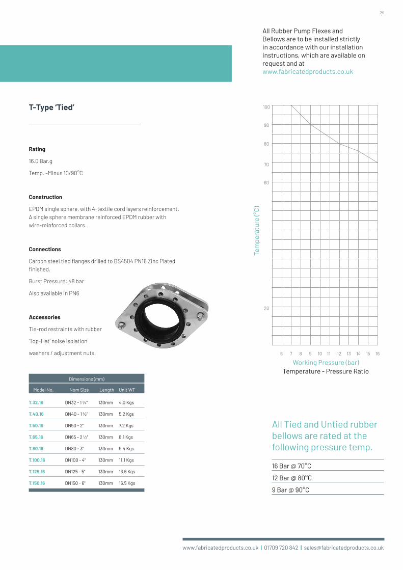
T-Type ‘Tied’
Rating
16.0 Bar.g
Temp. –Minus 10/90°C
Construction
EPDM single sphere, with 4-textile cord layers reinforcement. A single sphere membrane reinforced EPDM rubber with wire-reinforced collars.
Connections
Carbon steel tied flanges drilled to BS4504 PN16 Zinc Plated finished.
Burst Pressure: 48 bar
Also available in PN6
Accessories
Tie-rod restraints with rubber
‘Top-Hat’ noise isolation
washers / adjustment nuts.
All Rubber Pump Flexes and Bellows are to be installed strictly in accordance with our installation instructions, which are available on request and at www.fabricatedproducts.co.uk
All Tied and Untied rubber bellows are rated at the following pressure temp.
16 Bar @ 70°C
12 Bar @ 80°C
9 Bar @ 90°C
6 7 8 9 10 11 12 13 14 15 16
20
100
90
80
70
60
Tem
pera
ture
(°C)
Working Pressure (bar)Temperature - Pressure Ratio
T.32.16 DN32 - 1 1/4" 130mm 4.0 Kgs
T.40.16 DN40 - 1 1/2" 130mm 5.2 Kgs
T.50.16 DN50 - 2" 130mm 7.2 Kgs
T.65.16 DN65 - 2 1/2" 130mm 8.1 Kgs
T.80.16 DN80 - 3" 130mm 9.4 Kgs
T.100.16 DN100 - 4" 130mm 11.1 Kgs
T.125.16 DN125 - 5" 130mm 13.6 Kgs
T.150.16 DN150 - 6" 130mm 16.5 Kgs
Model No.
Dimensions (mm)
Nom Size Length Unit WT

30
www.fabricatedproducts.co.uk | 01709 720 842 | [email protected]
Pressure & Temperature Gauges
• Vertical Immersion & centre back type
• Immersion length 50mm or 100mm
• Bezel chrome plated
• Case material mild steel
• 100mm diameter
• Internal material Brass and bronze
• Socket & tube material Brass
• Connection 1/2" Temperature gauge
• Glass Window
• Temperature range 0 to 120 degrees Celsius (Heating)
• -30 to 50 degrees Celsius (Chilled water)
• Dual Scale reading accurate + / -1%
HVAC Bi / Metal Dial Thermometers
• Quality Bourdon Movement
• Pressure gauges range 0 to 4, 7 & 10 bar
• BS EN837-1
• Black Steel Case
• Bezel chrome plated
• Direct mounting
• 100mm diameter
• Glass window
• 3/8 BSP Bottom connection
• Standard Brass Internals
• Dual Scale reading accurate + / -1%
HVAC Pressure Gauges
PG04 3/8" Press. Gauge 0 to 4 bar - - Bottom
PG07 3/8" Press. Gauge 0 to 7 bar - - Bottom
PG010 3/8" Press. Gauge 0 to 10 bar - - Bottom
TG120CB50 1/2" Press. Temp Gauge 0 to 120 degrees 50mm Centre back connection
TG120CB100 1/2" Press. Temp Gauge 0 to 120 degrees 100mm Centre back connection
TG120B50 1/2" Press. Temp Gauge 0 to 120 degrees 50mm Bottom connection
TG120B100 1/2" Press. Temp Gauge 0 to 120 degrees 100mm Bottom connection
TG3050CB50 1/2" Press. Temp Gauge -30 to 50 degrees 50mm Centre back connection
TG3050CB100 1/2" Press. Temp Gauge -30 to 50 degrees 100mm Centre back connection
TG3050B50 1/2" Press. Temp Gauge -30 to 50 degrees 50mm Bottom connection
TG3050B100 1/2" Press. Temp Gauge -30 to 50 degrees 100mm Bottom connection
SYPRINGGMS 3/8" Ring Pattern Syphon - - Mild Steel
SYPRINGBRASS 3/8" Ring Pattern Syphon - - Brass
SYPUBRASS 3/8" “U” Pattern Syphon - - Brass
SYPUMS 3/8" “U” Pattern Syphon - - Mild Steel
BGCOCKFF 3/8" Brass gauge cock - - Brass with Polypropylene hand/BSP/F/F connections
Model No. Description Temp Range C & F Stem Length Mounting/Material
Brass gauge cock with polypropylene handle. 3/8" BSP female connections Max working pressure 10 bar
Ring Pattern Syphon 3/8" BSP polished Brass & mild Steel Max working pressure 10 bar
“U” Pattern Syphon 3/8" BSP polished Brass & mild Steel Max working pressure 10 bar

31
www.fabricatedproducts.co.uk | 01709 720 842 | [email protected]
Pressure & Temperature Gauges MicroVent
The Solution
The MicroVent is the reliable and worry-free solution ideal for:
• Filling and venting systems
• Making and keeping the high points in pipe systems air-free
• Preventing air pockets from forming
The Benefits
The combination of the characteristics listed below ensures that the automatic MicroVent will not leak during its very long life:
• The exceptional valve construction means that the valve closes completely
• The unique valve seat has a very long life expectancy
• The robust floats are made of solid plastic so cannot rupture
• The significant gap between the valve and the water (at least 40mm) prevents valve contamination which is one of the main causes of leaks
• The ½" connection prevents the pipette effect
• At the base of the MicroVent there is a wire mesh to stop debris from entering the unit
To remove trapped air you should fit a MicroVent at the highest points of the heating or chilled water systems.
Air collects at the highest point within a system. However, a system will often have several high points. Trapped air can obstruct the flow of water at these points or even stop it altogether. If air is not removed, it can lead to commissioning problems, frequent manual venting also deteriorating pump
performance and boiler efficiency. Eventually, this will cause damage to expensive system components and lead to system and process malfunctions or even total failure.
MicroVent automatic air vents are designed to remove free air and trapped air bubbles quickly and effectively. If a system has to be drained, the MicroVent ensures fast and reliable venting.
DesignMax. Pressure: 10 bar–g
Max. Temperature: 110ºC
Design Standards: Factory Standards
Net Weight: Factory Standards
MaterialBody: Stainless Steel Air
Vent: Stainless Steel
Seal: EPDM
Float: PE
TestLeakage Test: Yes
Appearance Test: Yes
Factory Air Test: Yes
Factory Water Test: Yes
Factory Test Certificate: Yes
Stainless Steel Automatic Air Vent that removes trapped air from heating or chilled water systems
120
R1/2
dØ65
Sized: ½" BSP

www.fabricatedproducts.co.uk | 01709 720 842 | [email protected]
Global ServiceOur services are utilised by many companies within the Water Treatment, Heating & Ventilation Industry throughout the UK, Europe, Scandinavia, the Middle East, Asia and as far as Australia.
Our products are installed worldwide in commercial and industrial applications such as hospitals, schools, universities, M.O.D bases, petro chemical plants, leisure centres, office blocks etc.
Other aspects of our business include product design and testing, including quality control to British Standards where applicable.
Your local distributor:UK Office
Unit 1 Fullerton Road Rotherham
S60 1DH United Kingdom
Tel: +44 (0) 1709 720 842 Fax: +44 (0) 1709 720 846
email: [email protected] www.fabricatedproducts.co.uk