WIT FOR POST-INSTALLED REBAR
18
WIT FOR POST-INSTALLED REBAR 36 POST -INSTALLED REBAR 4. Post-installed Reinforcement 4.1. General The following chapter explains the design theory behind post-installed reinforcement bar (rebar) applications and is intended to provide the reader with a basic understan- ding on the design requirements related to the Eurocode EN 1992-1-1 and the European Assessment Document (EAD) 330087-00-0601. Table 1 provides an overview of the specifications of our WIT-Rebar systems: Table 1: Specification overview of WIT-Rebar systems WIT-PE 1000 WIT-UH 300 WIT-PE 510 WIT-VM 250 European Technical Assessment ETA-19/0543 ETA-17/0036 ETA-20/1037 ETA-12/0166 Material Two-component re- active resin mortar, pure epoxy Urethane vinyl ester hybrid mortar Two-component reactive resin mor- tar, pure epoxy Two-component reaction resin mor- tar, vinyl ester REBAR diameter 8 – 40 mm 8 – 32 mm 8 – 40 mm 8 – 32 mm Drill hole cleaning with hollow drill-bit system ✔ ✔ ✔ X Gelling- / working time at 20°C 30 min 3 min 30 min 6 min Minimum curing time in dry concrete at 20°C 12 h 30 min 12 h 45 min Minimum curing time in wet concrete at 20°C 24 h 60 min 24 h 90 min Maximum embedment depth l v,max 2000 mm 2000 mm 2000 mm 2000 mm Temperature of base material in-service -40°C – +80°C -40°C – +80°C -40°C – +80°C -40°C – +80°C Temperature of base mate- rial at installation +5°C – +40°C -5°C – +40°C +5°C – +40°C -10°C – +40°C Fire resistance / Seismic / 100 years ✔ / ✔ / ✔ ✔ / ✔ / ✔ ✔ / X / X ✔ / X / X Software / Eurocode ✔ / ✔ ✔ / ✔ ✔ / ✔ ✔ / ✔
Transcript of WIT FOR POST-INSTALLED REBAR

WIT FOR POST-INSTALLED REBAR
36
POST -INSTALLED REBAR
4. Post-installed Reinforcement4.1. General
The following chapter explains the design theory behind post-installed reinforcement bar (rebar) applications and is intended to provide the reader with a basic understan-
ding on the design requirements related to the Eurocode EN 1992-1-1 and the European Assessment Document (EAD) 330087-00-0601.
Table 1 provides an overview of the specifications of our WIT-Rebar systems:
Table 1: Specification overview of WIT-Rebar systems
WIT-PE 1000 WIT-UH 300 WIT-PE 510 WIT-VM 250
European Technical Assessment
ETA-19/0543 ETA-17/0036 ETA-20/1037 ETA-12/0166
MaterialTwo-component re-active resin mortar,
pure epoxy
Urethane vinyl ester hybrid mortar
Two-component reactive resin mor-
tar, pure epoxy
Two-component reaction resin mor-
tar, vinyl ester
REBAR diameter 8 – 40 mm 8 – 32 mm 8 – 40 mm 8 – 32 mm
Drill hole cleaning with hollow drill-bit system
✔ ✔ ✔ X
Gelling- / working time at 20°C
30 min 3 min 30 min 6 min
Minimum curing time in dry concrete at 20°C
12 h 30 min 12 h 45 min
Minimum curing time in wet concrete at 20°C
24 h 60 min 24 h 90 min
Maximum embedment depth lv,max
2000 mm 2000 mm 2000 mm 2000 mm
Temperature of base material in-service
-40°C – +80°C -40°C – +80°C -40°C – +80°C -40°C – +80°C
Temperature of base mate-rial at installation
+5°C – +40°C -5°C – +40°C +5°C – +40°C -10°C – +40°C
Fire resistance / Seismic / 100 years
✔ / ✔ / ✔ ✔ / ✔ / ✔ ✔ / X / X ✔ / X / X
Software / Eurocode ✔ / ✔ ✔ / ✔ ✔ / ✔ ✔ / ✔

37
POST
-INS
TALL
ED R
EBAR
4.2. Anchor Theory vs. Rebar Theory Table 2 shows a comparison of potential failure modes for rebar used as anchor and post-installed rebar connection.
Table 2: Comparison of potential failure modesRebar used as Anchor (EN 1992-4) Post-installed Rebar Connection (EN 1992-1-1)
Failure modes in Tension Failure modes in Shear Failure modes in Tension Failure modes in Shear
Steel failure of fastener Steel failure of fastener without lever arm
Steel failure of reinforcing bar
Steel failure of fastener with lever arm
Bond failure
Pull-out failure of fastener Concrete pry-out failure Splitting failure
Combined pull-out and concrete failure
Concrete edge failure
Concrete cone failure
Splitting failure
4.2.1. Rebar used as Anchor
Situations where the concrete needs to take up tension loads from the anchorage or where reinforcing bars are designed to carry shear loads should be considered as “rebar used as anchors” and designed according to anchor design method such as given e.g. in the guidelines of EN 1992-4 or simplified in this Design Manual. Those guidelines verify all possible failure loads in tension and shear.
4.2.2. Post-installed Rebar Connection
The design of the rebar anchorage is performed accor-ding to structural concrete design codes, e.g. EN 1992-1-1. With a given test regime and the assess-ment criteria EAD 330087, it is proven that the load transfer for post-installed reinforcing bars is similar to cast in bars if the stiffness of the overall load transfer mecha-nism is similar to the cast-in system. The efficiency depen-ds on the strength of the adhesive mortar against the concentrated load close to the ribs and on the capacity of load transfer at the interface of the drilled hole.
In many cases the bond values of post-installed bars are higher compared to cast in bars due to better per-formance of the adhesive mortar. But for small edge
distance and/or narrow spacing, splitting or spalling forces become decisive due to the low tensile capacity of the concrete. 4.3. Post-installed rebar anchorage - The assessment criteria of EOTA-EAD 330087
The guideline specifies a number of tests in order to qua-lify products for post-installed rebar applications. These are the performance areas checked by the tests:
1. Bond strength in different strengths of concrete2. Substandard hole cleaning in dry and wet concrete3. Influence of temperature4. Correct injection5. Installation direction6. Influence of sustained loads7. Freeze-thaw conditions8. High alkalinity and sulphurous atmosphere9. Corrosion resistance10. Resistance to fire
If an adhesive meets all assessment criteria, rebar con-nections carried out with this adhesive can be designed with the bond strength and minimum anchorage length according to EN 1992-1-1 as given in the tables below for different Würth injection mortars.
WIT FOR POST-INSTALLED REBAR
38
POST -INSTALLED REBAR
Adhesives (or in conjunction with a certain drilling proce-dure) which do not fully comply with all assessment crite-ria can still obtain an approval: • If the bond strength obtained in tests does not fulfil the specified requirements, then bond strengths lower than those given by EN 1992-1-1 shall be applied. These values are given in the respective approval. • If it cannot be shown that the bond strength of reinforcing bars post-installed with a selected product and cast-in reinforcing bars in cracked concrete (w = 0.3 mm) is similar, then the minimum anchorage length lb,min and the minimum overlap length l0,min shall be increased by a factor 1.5.
4.4. Rebar Applications
Products tested according to above guideline can be used for applications in non-carbonated concrete C12/15 to C50/60 (EN 206) only, which are also allo-wed with straight deformed cast-in bars according to (EN 1992), e.g. those in the following applications:
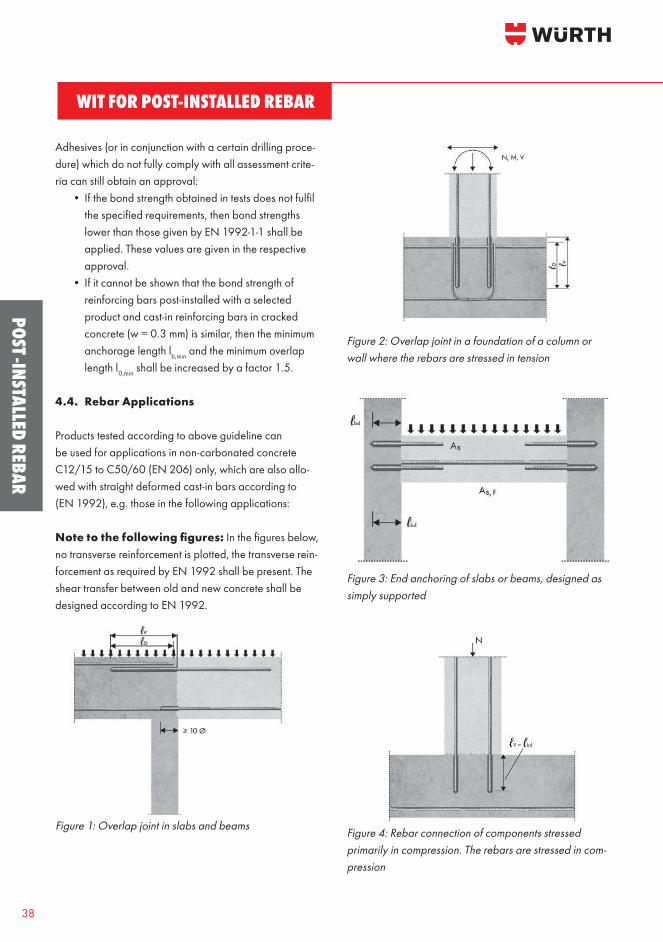
Note to the following figures: In the figures below, no transverse reinforcement is plotted, the transverse rein-forcement as required by EN 1992 shall be present. The shear transfer between old and new concrete shall be designed according to EN 1992.
Figure 1: Overlap joint in slabs and beams
Figure 2: Overlap joint in a foundation of a column or wall where the rebars are stressed in tension
Figure 3: End anchoring of slabs or beams, designed as simply supported
Figure 4: Rebar connection of components stressed primarily in compression. The rebars are stressed in com-pression

39
POST
-INS
TALL
ED R
EBAR
Figure 5: Anchoring of reinforcement to cover the line of acting tensile force
4.5. Design of Anchorage of longitudinal reinforcement with EN 1992-1-1
a) Reinforcing bars shall be so anchored that the bond forces are safely transmitted to the concrete avoiding longitudinal cracking or spalling. Transverse rein- forcement shall be provided if necessary.
b) The ultimate bond strength shall be sufficient to prevent bond failure.
4.5.1. The design value of the ultimate bond stress
where:• fck, 0.05 … is the 5% fractile charactersitic tensile strength of concrete according to Table 3• η1 … is a coefficient related to the quality of the bond condition and the position of the bar during concreting (details see EN 1992-1-1): o η1 = 1.0 when good conditions are obtained and o η1 = 0.7 for all other cases and for bars in structural elements built with slip-forms, unless it can be shown that good bond conditions exist• η2 … is related to the bar diameter: o η2 = 1.0 for ∅ ≤ 32 mm o η2 = (132 - ∅)/100 for ∅ > 32 mm
Table 3: Strength characteristics for concrete Compressive strength class C12/15 C16/20 C20/25 C25/30 C30/37 C35/45 C40/50 C45/55 C50/60
fck [N/mm2] 12 16 20 25 30 35 40 45 50
fck,cube [N/mm2] 15 20 25 30 37 45 50 55 60
fcm [N/mm2] 20 24 28 33 38 43 48 53 58
fctm [N/mm2] 1.60 1.90 2.20 2.60 2.90 3.20 3.50 3.80 4.10
fctk, 0.05 [N/mm2] 1.10 1.30 1.50 1.80 2.00 2.20 2.50 2.70 2.90
fctk, 0.95 [N/mm2] 2.00 2.50 2.90 3.30 3.80 4.20 4.60 4.90 5.30
fbd Ø ≤ 32 [N/mm2] 1.65 1.95 2.25 2.70 3.00 3.30 3.75 4.05 4.35
fbd Ø ≤ 34 [N/mm2] 1.62 1.91 2.21 2.65 2.94 3.23 3.68 3.97 4.26
fbd Ø ≤ 36 [N/mm2] 1.58 1.87 2.16 2.59 2.88 3.17 3.60 3.89 4.18
fbd Ø ≤ 40 [N/mm2] 1.52 1.79 2.07 2.48 2.76 3.04 3.45 3.73 4.00
WIT FOR POST-INSTALLED REBAR
40
POST -INSTALLED REBAR
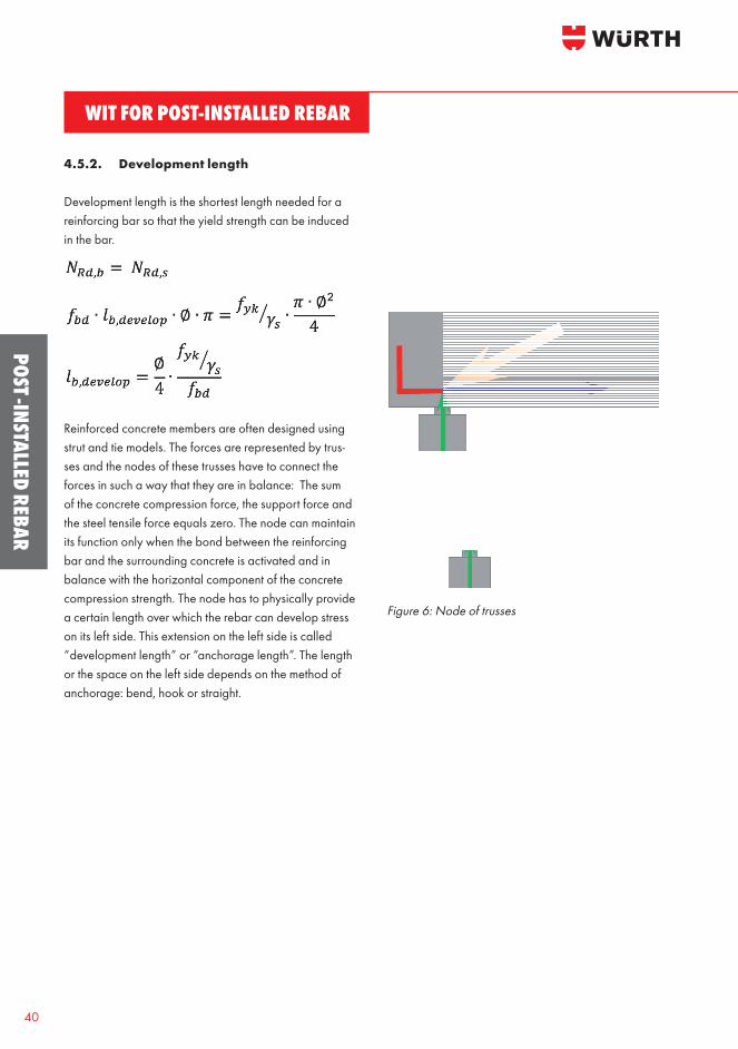
4.5.2. Development length
Development length is the shortest length needed for a reinforcing bar so that the yield strength can be induced in the bar.
Reinforced concrete members are often designed using strut and tie models. The forces are represented by trus-ses and the nodes of these trusses have to connect the forces in such a way that they are in balance: The sum of the concrete compression force, the support force and the steel tensile force equals zero. The node can maintain its function only when the bond between the reinforcing bar and the surrounding concrete is activated and in balance with the horizontal component of the concrete compression strength. The node has to physically provide a certain length over which the rebar can develop stress on its left side. This extension on the left side is called “development length” or “anchorage length”. The length or the space on the left side depends on the method of anchorage: bend, hook or straight.
Figure 6: Node of trusses

41
POST
-INS
TALL
ED R
EBAR
Tabl
e 4:
Des
ign
load
s for
goo
d bo
nd c
ondi
tions
Bar size
Cross sectional area of reinforcement
Characteristic yield strength
Partial factor for reinforcing steelDesign resistance of rein-forcement bar
Design Bond stress
Development length
Minimum anchorage length
Des
ign
load
for g
ood
bond
con
ditio
n, C
20/2
5
ØA s
f ykȣ s
NRd
,sf bd
l bdl b,
min
Nb,
d
[mm
][m
m2 ]
[N/m
m2 ][k
N]
[N/m
m2 ][m
m]
[kN
]
850
.350
01.
1521
.92.
2538
611
67
78
811
1417
20-
--
--
--
--
--
--
--
--
-
1078
.550
01.
1534
.12.
2548
314
5-
--
1114
1821
2528
--
--
--
--
--
--
--
--
-
1211
3.1
500
1.15
49.2
2.25
580
174
--
--
1721
2530
3442
--
--
--
--
--
--
--
--
1415
3.9
500
1.15
66.9
2.25
676
203
--
--
-25
3035
4049
59-
--
--
--
--
--
--
--
1620
1.1
500
1.15
87.4
2.25
773
232
--
--
-28
3440
4557
6879
--
--
--
--
--
--
--
2031
4.2
500
1.15
136.
62.
2596
629
0-
--
--
-42
4957
7185
9911
312
7-
--
--
--
--
--
-
2549
0.9
500
1.15
213.
42.
2512
0836
2-
--
--
--
-71
8810
612
414
115
917
719
421
2-
--
--
--
--
2861
5.8
500
1.15
267.
72.
2513
5340
6-
--
--
--
--
9911
913
915
817
819
821
823
825
7-
--
--
--
-
3280
4.2
500
1.15
349.
72.
2515
4646
4-
--
--
--
--
113
136
158
181
204
226
249
271
294
317
339
--
--
--
3490
7.9
500
1.15
394.
72.
2116
7650
3-
--
--
--
--
-14
116
518
821
223
625
928
330
633
035
337
7-
--
--
3610
17.9
500
1.15
442.
62.
1618
1254
3-
--
--
--
--
-14
717
119
522
024
426
929
331
834
236
639
141
544
0-
--
4012
56.6
500
1.15
546.
42.
0721
0063
0-
--
--
--
--
-18
220
823
426
028
631
233
836
439
041
644
246
849
452
054
6
Anch
orag
e le
ngth
[mm
]12
013
014
015
020
025
030
035
040
050
060
070
080
090
010
0011
0012
0013
0014
0015
0016
0017
0018
0019
0020
0021
00
WIT FOR POST-INSTALLED REBAR
42
POST -INSTALLED REBAR
4.5.3. Basic anchorage length
The calculation of the required anchorage length shall take into consideration the type of steel and bond pro-perties of the bars. The basic required anchorage length lb,rqd for anchoring the force As.σsd in a bar assuming con-stant bond stress equal to fbd follows from:
4.5.4. Design anchorage length
According to EN 1992-1-1, the design anchorage length, lbd is
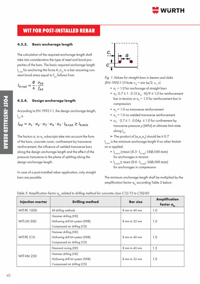
The factors a1 to a5 subscripts take into account the form of the bars, concrete cover, confinement by transverse reinforcement, the influence of welded transverse bars along the design anchorage length and the effect of the pressure transverse to the plane of splitting along the design anchorage length. In case of a post-installed rebar application, only straight bars are possible.
Fig. 1: Values for straight bars in beams and slabs (EN 1992-1-1) Note: cd = min (a/2, c1, c) • α1 = 1.0 for anchorage of straight bars • α2: 0.7 ≤ 1 - 0.15 (cd - ∅)/∅ ≤ 1.0 for reinforcement bar in tension or a2 = 1.0 for reinforcement bar in compression • α3 = 1.0 no transverse reinforcement • α4 = 1.0 no welded transverse reinforcement • α5: 0.7 ≤ 1 - 0.04ρ ≤ 1.0 for confinement by transverse pressure ρ [MPa] at ultimate limit state along lbd
➢The product of (α2α3α5) should be ≥ 0.7.lb,min is the minimum anchorage length if no other limitati-on is applied: • lb,min ≥max (0.3 ∙ lb,rqd; 10∅;100 mm) for anchorages in tension • lb,min≥ max (0.6 ∙ lb,rqd; 10∅;100 mm) for anchorages in compression
The minimum anchorage length shall be multiplied by the amplification factor αlb according Table 5 below:
Table 5: Amplification factor alb related to drilling method for concrete class C12/15 to C50/60
Injection mortar Drilling method Bar sizeAmplification
factor alb
WIT-PE 1000 All drilling methods 8 mm to 40 mm 1.0
WIT-UH 300Hammer drilling (HD)
Hollowing drill bit system (HDB)
Compressed air drilling (CD)
8 mm to 32 mm 1.0
WIT-PE 510Hammer drilling (HD)
Hollowing drill bit system (HDB)
Compressed air drilling (CD)
8 mm to 40 mm 1.0
WIT-VM 250
Diamond coring (DD) 8 mm to 40 mm 1.5Hammer drilling (HD)
Hollowing drill bit system (HDB)
Compressed air drilling (CD)
8 mm to 32 mm 1.0

43
POST
-INS
TALL
ED R
EBAR
4.5.5. Lap or splice length
According to EN 1992-1-1, the design lap length isl0 = α1 ∙ α2 ∙ α3 ∙ α5 ∙ α6 ∙ lb,rqd ≥ l0,min
• α1 = 1.0 for anchorage of straight bars • α2 = 1.0 for reinforcement bar in compression • α2: 0.7 ≤ 1 - 0.15 (cd - ∅)/∅ ≤ 1.0 for reinforcement bar in tension
• α3 = 1.0 no transverse reinforcement • α5: 0.7 ≤ 1 - 0.04ρ ≤ 1.0 for confinement by transverse pressure ρ [MPa] along lbd
• α6: 1.0 ≤ α6 ≤ 1.5 for influence of percentage of lapped bars relative to the total cross-section area according to the following table:
Table 6: Values of the coefficient
Percentage of lapped bars relative to the total cross-section area < 25% 33% 50% >50%
a6 1.00 1.15 1.40 1.50Note: Intermediate values may be determined by interpolation
➢The product of (α2α3α5) should be ≥ 0.7.
l0,min is the minimum lap length:
l0,min ≥ max (0.3 ∙ α6 ∙ lb,rqd; 15∅; 200 mm)
The minimum lap length shall be multiplied by the amplifi-cation factor αlb according Table 5.
4.5.6. Concrete cover
Concrete cover is defined as the minimum distance between the outer surface of the concrete element and the surface of the embedded reinforcement. The nominal concrete cover is defined as a minimum cover plus a deviation allowance △cdev. The recommended value for △cdev = 10 mm.cnom= cmin + △cdev
The minimum concrete cover cmin is to ensure safe trans- mission of bond forces and protection against steel and fire is defined according to the following equation:
cmin = max (cmin,b;cmin,dur;10 mm)
where• cmin,b = minimum cover due to bond requirement• cmin,dur = minimum cover due to environmental conditions
a) cmin,b is equivalent to the diameter of the reinforcing bar.
b) cmin,dur can be obtained from Table 8:
Table 8: Values of minimum cover cmin,dur requirements with regard to durability for reinforcement steel
Exposure Class
X0 XC1 XC2/XC3 XC4 XD1/XS1 XD2/XS2 XD3/XS3
Stru
ctur
al C
lass
S1 10 10 10 15 20 25 30
S2 10 10 15 20 25 30 35
S3 10 10 20 25 30 35 40
S4 10 15 25 30 35 40 45
S5 15 20 30 35 40 45 50
S6 20 25 35 40 45 50 55

WIT FOR POST-INSTALLED REBAR
44
POST -INSTALLED REBAR
According to the exposure class in a given situation, the table below from EN 1992-1-1 further provides the engineer with the indicative minimum concrete strength class for each exposure class:
Table 9: Indicative minimum strength class
Corrosion
Carbonation-induced corrosionChloride-induced
corrosion
Chloride-induced corrosion from
sea-waterXC1 XC2 XC3 XC4 XD1 XD2 XD3 XS1 XS2 XS3
Indicative minimum strength class
C20/25 C25/30 C30/37 C30/37 C35/45 C30/37 C35/45
Damage to Concrete
No risk Freeze/Thaw Attack Chemical AttackX0 XF1 XF2 XF3 XA1 XA2 XA3
Indicative minimum strength class
C12/15 C30/37 C25/30 C30/37 C30/37 C35/45
For our WIT-Rebar systems, the concrete cover shall be defined as minc = max (cnom;cmin,inst)
The minimum cover of post-installed reinforcing bars cmin,inst depends on the drilling method:
Table 10: Minimum cover related to drilling method
Drilling methodRebar diameter
(∅)Without
drilling aidWith drilling aid
Hammer drilling (HD) Hollow drill bit system (HDB)
< 25 mm 30 mm + 0.06 lv ≥ 2∅ 30 mm + 0.02 lv ≥ 2 ∅
≥ 25 mm 40 mm + 0.06 lv ≥ 2∅ 40 mm + 0.02 lv ≥ 2 ∅
Diamond drilling (DD)< 25 mm
Drill rig used as drilling aid30 mm + 0.02 lv ≥ 2 ∅
≥ 25 mm 40 mm + 0.02 lv ≥ 2 ∅
Compressed air drilling< 25 mm 50 mm + 0.08 lv 50 mm + 0.02 lv≥ 25 mm 60 mm + 0.08 lv 60 mm + 0.02 lv
Comment: The minimum concrete cover acc. EN 1992-1-1:2004+AC:2010 must be observed

45
POST
-INS
TALL
ED R
EBAR
4.5.7. Spacing of bars and laps
The spacing of bars shall be such that the concrete can be placed and compacted satisfactorily for the develop-ment of adequate bond. The clear distance (horizontal and vertical) between individual parallel bars or hori-zontal layers of parallel bars should be not less than the max(∅; (dg + 5 mm) or 20 mm) where dg is the maximum size of aggregate (8.2; EN 1992-1-1:2011-01).
Figure 7: Adjacent laps
The spacing between post-installed reinforcing bars shall be greater max (5∅; 50 mm).
4.5.8. Embedment depth
Embedment depth for overlap jointsFor calculation of the effective embedment depth of overlap joints the concrete cover at end-face of bonded-in rebar c1 shall be considered: lv ≥ l0 + c1
If the clear distance between the overlapping rebar is greater than 4 Ø the lap length shall be enlarged by the difference between the clear distance and 4 Ø.
4.5.9. Maximum embedment depth
Table 11: Maximum approved embedment depth for WIT-Rebar systems
Bar size, ∅ [mm] 8 10 12 14 16 20 25 28 32 34 36 40
MortarDrilling
Method *Maximum permissible embedment depth, lmax [mm]
WIT-PE 1000HD / CD / DD 800 1000 1200 1400 1600 2000 2000 2000 2000 2000 2000 2000
HDB 800 1000 1000 1000 1000 1000 1000 1000 1000 - - -
WIT-UH 300 All methods 1000 1000 1200 1400 1600 2000 2000 2000 2000 - - -
WIT-PE 510HD / CD / DD 800 1000 1200 1400 1600 2000 2000 2000 2000 2000 2000 2000
HDB 800 1000 1000 1000 1000 1000 1000 1000 1000 - - -
WIT-VM 250 All methods 1000 1000 1200 1400 1600 2000 2000 1000 1000 - - -* HD = Hammer drilling, CD = Compressed air drilling, HDB = Hollow drill bit system, DD = Diamond drilling

WIT FOR POST-INSTALLED REBAR
46
POST -INSTALLED REBAR
4.5.10. Transverse reinforcement
The requirements of transverse reinforcement in the area of the post-installed rebar connection shall comply with EN 1992-1-1, Section 8.7.4.
4.5.11. Connection joint
The transfer of shear forces between new concrete and existing structure shall be designed according to EN 1992-1-1, Section 6.2.5 “Shear at the interface between concrete cast at different times”. The joints for concreting must be roughened to at least such an extent that aggregate protrude. In case of a carbonated surface of the existing concrete structure the carbonated layer shall be removed in the area of the post-installed rebar connection with a diameter of (Ø + 60 mm) prior to the installation of the new rebar. The depth of concrete to be removed shall correspond to at least the minimum concrete cover for the respective environmental conditions in accordance with EN 1992-1-1. The foregoing may be neglected if building components are new and not carbo-nated and if building components are in dry conditions.
4.5.12. Failure modes and anchorage length
In most cases the reinforcement bars are placed close to the surface of the concrete member to achieve good crack distribution and economical bending capacity. For splices at wide spacing, the bearing capacity of the concrete depends only on the thickness of the concrete cover. At narrow spacing the bearing capacity depends on the spacing and on the thickness of the cover. In the design codes the reduction of bearing capacity of the cover is taken into account by means of multiplying factors for the splice length. Splitting failure is decisive if the radial cracks propagate through the entire cover. Bond failure is caused by pull-out of the bar if the confinement (concrete cover, transverse reinforcement) is sufficient to prevent splitting of the concrete cover. EN 1992-1-1 controls the failure modes by limiting the α2 value to α2 ≥ 0.7. The spalling of the concrete cover or splitting between bars will be the controlling mode of failure. The value α2 gives an explicit consideration for
splitting and spalling as a function of concrete cover and bar spacing.
If α2 is less than 0.7, corresponding to cover dimensions of cd/∅ > 3 or spacing of a/∅ > 6, the cover or spacing is large enough so that splitting cannot occur anymore and pull-out will control.
4.6. Fire load case
4.6.1. General information
The load-bearing capacity in case of fire corresponds to the performance characteristic R according to DIN EN 13501-2. A classification of performance characteristics in case of fire according to DIN EN 13501-2 requires a time-dependent fire stress according to the unit tempera-ture time curve (ETK), which is defined in DIN EN 13631. The National Annex to DIN EN 1991-1-2 also requires the application of standard time/temperature curve at any point of the structure for structural elements in building construction. If a sufficient load-bearing capacity under ETK load has been verified, this verification applies irrespective of the later use.
Figure 8: Standard time/temperature curve ISO 834
4.6.2. Application cases
To determine the load-bearing capacity of reinforcement connections in the event of fire, a basic distinction must be made between two applications. In application A, the thermally stressed surface shows the same direction as the reinforcement, which leads to a locally constant but time-varying temperature along the anchorage length lbd.

47
POST
-INS
TALL
ED R
EBAR
Figure 9: Fire load case - Application A
Alternatively for application B, the post-installed rebar is perpendicular to the thermally stressed surface, which results in a temporally and spatially variable temperature profile along the anchorage length lbd.
Figure 10: Fire load case - Application B
The distinction between application cases A and B is made exclusively according to the orientation of the flame-exposed surfaces in relation to the direction of the post-installed rebar and is not the same as the distinction between end anchoring and lap joint.
4.6.3. Load-bearing capacity
The load-bearing capacity of post-installed rebar connections in case of fire is significantly affected by the temperature-dependent bond stress fbd,fi (Θ) with
which is determined by experimental techniques. The reduction factor kfi (Θ) under fire stress, the design value fbd of the bond stress in cold case according to DIN EN 1992-1-1, which depends on the concrete strength class, and the reduction factor kb with fbd,PIR = kb. fbd are specified
in the relative ETA. According to DIN EN 1992-1-1, Table 2.1N in accordance with the corresponding national annex for the permanent and temporary design situation, the following applies to the partial safety factor of concre-te in cold conditions γc = 1.5In case of fire, the following applies according to DIN EN 1992-1-2, chapter 2.3 in accordance with the corres-ponding national appendix for the partial safety factor of concrete γM,fi = 1.0The design values fbd of the composite stress in cold case are shown in Table 3. The values are applicable for all drilling methods, but they depend on the reinforcement bar diameter and are valid for good bond conditions according to DIN EN 1992-1-1, chapter 8.4.2. In case of other bond conditions, the specified values have to be multiplied by a factor of 0.7.
For WIT-PE 1000, the factor kb can be found in ETA19/0543 in Table C2. kb = 1.0and thus for all cases fbd,PI = fbd
The temperature-dependent reduction factor kb,fi(Θ) is (de-pending on the ETA) to be considered. The graph below shows reduction factors kb,fi(Θ) for all WIT-Rebar systems for 8 mm ≤ d ≤ 32 mm.
Figure 11: Reduction factor for WIT-Rebar systems (drilling methods HD/HBD/CD) for 8 mm ≤ d ≤ 32 mm
When designing post-installed rebar connections in case of fire, a distinction must be made between pull-out failure and steel failure, in addition to the distinction between application cases A and B.
0,00
0,20
0,40
0,60
0,80
1,00
1,20
0 50 100 150 200 250 300 350
Redu
ctio
n fa
ctor
kb,
fi
Temperature (°C)
Reduction factor kb,fi for WIT--REBAR systems under good bond conditions for 8 mm ≤ d ≤ 32 mm
WIT-PE 1000
WIT-VM 250
WIT-UH 300
WIT-PE 510

WIT FOR POST-INSTALLED REBAR
48
POST -INSTALLED REBAR
4.6.4. Application case A
If the rebar connection in application A is in the same direction as the flamed surface, the function of the unit time-temperature curve results in a temperature along the rebar connection that varies over time but is locally constant. The time-dependent reinforcement temperature in case of fire is only dependent on the geometry of the existing component and the design in case of fire can be carried out using the time-dependent reinforcement tempe-rature Θ(t) and the time-dependent bond stress fbd,fi (Θ(t)).
4.6.4.1. Pull-out
If the stresses acting on a rebar connection are greater than the bond force that can be absorbed, failure occurs due to pull-out. The proof for the failure mode pull-out is performed in application A by determining the anchorage length lb,rqd,fi (t) required in case of fire. The value lb,rqd,fi (t) describes the basic value of the anchorage length in case of fire and is to be determined according to DIN EN 1992-1-1, equation (8.3) under consideration of the time- and temperature-dependent bond stress.
with • ∅ = diameter of the reinforcement bar • σsd,fi = existing steel stress of the bar at the beginning of the anchorage length in the ultimate limit state under extraordinary design situation according to DIN EN 1990
The design value lbd,fi (t) of the anchorage length in case of fire is obtained analogously to the check under normal temperature according to DIN EN 19921-1, chapter 8.4.4.
4.6.4.2 Steel failure
The temperature-dependent load capacity of the rebar itself is limited by the load capacity of the steel cross-section. According to DIN EN 1992-1-2, Chapter 5.2(4),
the reinforcement of statically determinate reinforced concrete structures may be verified in case of fire by means of a temperature criterion. The critical temperature is Θcrit = 500°C. The proof for steel failure is therefore provided if the following applies to the most unfavorable (i.e. warmest) point of the rebar in the post-installed rebar connection.
Alternatively, the verification of the reinforcing bar for steel failure in case of fire can be done by comparing the acting and the bond (tensile) force.
with Nfi,Ed: Stress on the bar at the beginning of the anchorage length in the ultimate limit state in case of an extraordinary design situation according to DIN EN 1990. The force that can be sustained in case of fire must be determined taking into account the temperature-dependent decrease of the yield strength according to DIN EN 1992-1-2, Table 3.2a.
You get the bond tensile force in case of fire as:
In case of fire, the following applies in accordance with DIN EN 1992-1-2, Chapter 2.3 in accordance with the corresponding National Annex for the partial safety factor of reinforcing steel
γM.fi = 1.0

49
POST
-INS
TALL
ED R
EBAR
Tabl
e 12
: Tem
pera
ture
for d
iffer
ent fi
re d
urat
ions
vs.
conc
rete
cov
erT
[°C]
with
mem
ber t
hick
ness
= 3
0 cm
c [cm
]Fir
e du
ratio
n [m
in]
30
60
90
120
1
80
240
2
348
5
16
614
6
84
783
8
53
3 2
42
399
4
96
566
6
67
740
4
167
3
11
403
4
71
571
6
44
5 1
17
241
3
28
394
4
91
564
6
88
187
2
68
330
4
24
495
7
68
144
2
18
277
3
67
435
8
53
114
1
77
232
3
18
384
9
42
93
143
1
93
275
3
39
10 3
4 7
7 1
18
161
2
38
299
11
29
64
100
1
35
205
2
64
12 2
6 5
4 8
5 1
15
177
2
33
13 2
4 4
6 7
3 9
9 1
53
205
14
22
39
63
87
132
1
80
15 2
1 3
4 5
5 7
6 1
16
159
16
21
30
48
67
103
1
40
17 2
0 2
7 4
2 5
9 9
2 1
25
18 2
0 2
5 3
7 5
2 8
3 1
12
19 2
0 2
4 3
3 4
6 7
5 1
02
20 2
0 2
3 3
0 4
2 6
7 9
3 21
20
22
28
38
61
85
22 2
0 2
1 2
6 3
4 5
5 7
9 23
20
21
25
31
51
72
24 2
0 2
1 2
3 2
9 4
7 6
7 25
20
20
23
27
43
63
Tabl
e 13
: Bon
d str
engt
h fo
r diff
eren
t fire
dur
atio
ns f bd
,fi [N
/mm
2] f
or m
embe
r thi
ckne
ss =
30
cm
Goo
d bo
nd c
ondi
tions
, C20
/25
8 m
m ≤
d ≤
32
mm
W
IT-PE
100
0W
IT-U
H 3
00
c [c
m]
Fire
dura
tion
[min
] 3
0 6
0 9
0 1
20
180
2
40
30
60
90
120
2
-
-
-
-
-
-
0.2
3 -
-
-
3
0.2
5 -
-
-
-
-
0
.74
-
-
-
4 0
.46
-
-
-
-
-
1.6
9 0
.35
-
-
5 0
.80
0.2
5 -
-
-
-
2
.91
0.7
4 0
.29
-
6 1
.26
0.3
8 0
.22
-
-
-
3.4
5 1
.36
0.5
6 0
.28
7 1
.93
0.5
8 0
.30
0.2
0 -
-
3
.45
2.1
7 0
.96
0.5
0 8
2.8
9 0
.84
0.4
2 0
.27
-
-
3.4
5 3
.03
1.5
2 0
.83
9 3
.45
1.1
6 0
.58
0.3
6 0
.21
-
3.4
5 3
.45
2.1
9 1
.26
10 3
.45
1.5
7 0
.80
0.4
8 0
.26
-
3.4
5 3
.45
2.8
9 1
.80
11 3
.45
2.1
1 1
.04
0.6
4 0
.33
0.2
2 3
.45
3.4
5 3
.45
2.4
0 12
3.4
5 2
.80
1.3
4 0
.84
0.4
2 0
.27
3.4
5 3
.45
3.4
5 3
.00
13 3
.45
3.4
5 1
.71
1.0
5 0
.53
0.3
3 3
.45
3.4
5 3
.45
3.4
5 14
3.4
5 3
.45
2.1
7 1
.30
0.6
6 0
.40
3.4
5 3
.45
3.4
5 3
.45
15 3
.45
3.4
5 2
.73
1.6
1 0
.82
0.5
0 3
.45
3.4
5 3
.45
3.4
5 16
3.4
5 3
.45
3.4
0 1
.98
0.9
9 0
.61
3.4
5 3
.45
3.4
5 3
.45
17 3
.45
3.4
5 3
.45
2.4
3 1
.18
0.7
3 3
.45
3.4
5 3
.45
3.4
5 18
3.4
5 3
.45
3.4
5 2
.95
1.4
0 0
.87
3.4
5 3
.45
3.4
5 3
.45
19 3
.45
3.4
5 3
.45
3.4
5 1
.66
1.0
1 3
.45
3.4
5 3
.45
3.4
5 20
3.4
5 3
.45
3.4
5 3
.45
1.9
5 1
.17
3.4
5 3
.45
3.4
5 3
.45
21 3
.45
3.4
5 3
.45
3.4
5 2
.29
1.3
4 3
.45
3.4
5 3
.45
3.4
5 22
3.4
5 3
.45
3.4
5 3
.45
2.6
6 1
.53
3.4
5 3
.45
3.4
5 3
.45
23 3
.45
3.4
5 3
.45
3.4
5 3
.07
1.7
4 3
.45
3.4
5 3
.45
3.4
5 24
3.4
5 3
.45
3.4
5 3
.45
3.4
5 1
.96
3.4
5 3
.45
3.4
5 3
.45
25 3
.45
3.4
5 3
.45
3.4
5 3
.45
2.1
9 3
.45
3.4
5 3
.45
3.4
5

WIT FOR POST-INSTALLED REBAR
50
POST -INSTALLED REBAR
4.6.5. Application case B
If the rebar connection in application B is perpendicular to the direction of the flamed surface, the temperature along the rebar connection changes over time and place - the temperature decreases with increasing distance from the flamed surface.
4.6.5.1. Pull out A design in case of fire for the failure type pull-out in the form of the determination of a single time-dependent composite stress fbd,fi (Θ(t)) is not sufficient for application B because this stress is variable along the reinforcement connection. A procedure analogous to application A would therefore result in an additional required anchoring length lb,rqd,fi (t) at each point of the rebar.
On the safe side, it is of course conceivable and permis-sible to determine the required anchorage length lb,rqd,fi (t) analogous to application A, taking into account the most unfavorable (i.e. highest) temperature of the rebar in the existing component. However, the results obtained in this way can be considered as extremely conservative with increasing anchorage length.
A more economical approach, which makes use of the actual load-bearing capacity of the bonded joint, is to prove pull-out failure in application B by comparing the acting and the absorbing forces
The bond force Nbd,fi,Rd (t) in the composite joint is obtained by integrating the temperature-dependent composite stress fbd,fi (Θ(t)) via the load-transmitting surface of the rebar
with lv : Development depth. The bond and acting forces are identical:
The development depth lv for a defined time t corresponds to the required anchorage length lb,rqd,fi (t) according to the corresponding ETA and DIN EN 1992-1-1, Equation (8.3). Analogous to the application case A and the cold case, the design value lbd,fi (t) of the anchorage length in case of fire shall be determined according to DIN EN 1992-1-1, chapter 8.4.4.
4.6.5.2. Steel failure
In contrast to the failure due to pull-out, the check for steel failure must be performed at the most unfavorable check section, i.e. taking into account the maximum tempera-ture occurring along the reinforcement bars at a given time t. The verification can be performed analogous to application A by means of the temperature criterion or by comparing the acting and the absorbing force.

51
POST
-INS
TALL
ED R
EBAR
Table 14: Tension load for different fire durationNbd,fi [kN] d = 16 mm
Good bond conditions, C20/25
WIT-PE 1000 WIT-UH 300
lv [cm]
Fire duration [min]30 60 90 120 180 240 30 60 90 120
16 20.1 13.6 8.4 4.8 2.2 1.2 24.8 20.0 16.4 13.418 23.5 17.1 12.2 7.7 3.5 2.0 28.3 23.5 19.9 16.920 27.0 20.5 15.7 11.5 5.3 3.0 31.7 26.9 23.3 20.422 30.5 24.0 19.1 15.1 7.9 4.5 35.2 30.4 26.8 23.924 33.9 27.5 22.7 18.6 11.4 6.4 38.7 33.9 30.3 27.325 35.7 29.3 24.3 20.3 13.4 7.7 40.4 35.6 32.0 29.126 37.4 30.9 26.1 22.1 15.2 9.1 42.1 37.4 33.7 30.828 40.9 34.4 29.5 25.6 18.8 12.6 45.6 40.8 37.2 34.330 44.3 37.9 33.0 29.1 22.4 16.5 49.1 44.3 40.7 37.832 47.8 41.4 36.5 32.5 25.8 20.1 52.5 47.8 44.2 41.234 51.3 44.8 39.9 36.0 29.3 23.7 56.0 51.2 47.6 44.736 54.7 48.3 43.4 39.5 32.8 27.2 59.5 54.7 51.1 48.238 58.2 51.8 46.9 42.9 36.2 30.7 62.9 58.2 54.6 51.740 61.7 55.3 50.3 46.4 39.7 34.2 66.4 61.6 58.0 55.145 70.3 63.9 59.0 55.1 48.4 42.8 75.1 70.3 66.7 63.850 79.0 72.5 67.7 63.7 57.1 51.5 83.7 79.0 75.4 72.455 87.7 81.2 76.4 72.4 65.7 60.2 92.4 87.6 84.0 81.160 96.4 89.9 85.1 81.1 74.4 68.8 101.1 96.3 92.7 89.865 105.0 98.6 93.7 89.7 83.0 77.5 109.8 105.0 101.4 98.570 113.7 107.3 102.4 98.4 91.7 86.2 118.4 113.7 110.1 107.175 122.4 115.9 111.1 107.1 100.4 94.8 127.1 122.3 118.7 115.880 131.0 124.6 119.7 115.7 109.1 103.5 135.8 131.0 127.4 124.485 139.7 133.3 128.4 124.4 117.7 112.2 144.4 139.7 136.1 133.190 148.4 141.9 137.1 133.1 126.4 120.9 153.1 148.3 144.7 141.895 157.1 150.6 145.8 141.8 135.1 129.5 161.8 157.0 153.4 150.5
100 165.7 159.3 154.4 150.4 143.8 138.2 170.5 165.7 162.1 159.1110 183.1 176.6 171.8 167.8 161.1 155.5 187.8 183.0 179.4 176.5120 200.4 193.9 189.1 185.1 178.5 172.9 205.1 200.4 196.8 193.8130 217.7 211.3 206.5 202.5 195.8 190.2 222.5 217.7 214.1 211.2140 235.1 228.6 223.8 219.8 213.1 207.6 239.8 235.0 231.4 228.5150 252.4 246.0 241.1 237.1 230.5 224.9 257.2 252.4 248.8 245.8160 269.8 263.3 258.5 254.5 247.8 242.3 274.5 269.7 266.1 263.2
*For other diameters and concrete strengths, please contact Würth technical support

WIT FOR POST-INSTALLED REBAR
52
POST -INSTALLED REBAR

53
Bibliography
European Committee for Standardization “EN 206 Concrete - Specification, performance, production and conformity”, 2006.
European Committee for Standardization, “Eurocode 0: Basis of structural design, EN 1990:2002+A1”, 2010.European Committee for Standardization, “Eurocode 1: Actions on structures - Part 1-1: General actions - Densi-ties, self-weight, imposed loads for buildings, EN 1991-1-1”, 2002.
European Committee for Standardization, “Eurocode 2: Design of concrete structures — Part 1-1: General rules and rules for buildings, EN 1992-1-1”, 2004.
European Committee for Standardization, “Eurocode 2: Design of concrete structures - Part 1-2: General rules - Structural fire design, EN 1992-1-2”, 2004.
European Committee for Standardization, “Eurocode 2: Design of concrete structures - Part 4: Design of fasten-ings for use in concrete; EN 1992-4”, 2018.
European Committee for Standardization, “Eurocode 3: Design of steel structures - Part 1-1: General rules and rules for buildings, EN 1993-1-1”, 2005.
European Committee for Standardization, “Eurocode 8: Design of structures for earthquake resistance - Part 1: General rules, seismic actions and rules for buildings; EN 1998-1:2004”.
DIN EN 13501-2: Fire Classification of Construction Pro-ducts and Building Elements - Part 2: Classification Using Data From Fire Resistance Tests, Excluding Ventilation Services: 2016.
Reichel, D.-E. (2020, October). Tragverhalten Nachträg-licher Bewehrungsanschlüsse im Brandfall am Beispiel des Würth Injektionssystems WIT-PE 1000 (Load Beha-vior of Post-installed Reinforcement in the Event of Fire with the Example of the Würth Injection System WIT-PE 1000). ql^2/8, pp. 16-25.