Wisconsin Focus on Energy
94
Wisconsin Focus on Energy Home Performance with ENERGY STAR Program & Assisted Home Performance Program Material and Installation Standard Version 2.0 February 16, 2012 2821 Dairy Drive | Madison, WI 53718 | 608-729-9100
Transcript of Wisconsin Focus on Energy

Wisconsin Focus on Energy Home Performance with ENERGY STAR Program
& Assisted Home Performance Program Material and Installation Standard
Version 2.0 February 16, 2012
2821 Dairy Drive | Madison, WI 53718 | 608-729-9100

Focus on Energy | HPwES & Assisted HP | 2/16/12 Page 2 of 94
Table of Contents
1.0 OVERVIEW 4
1.1 Organization 4
1.2 Work Related Standards & Regulations 4
2.0 MATERIAL AND INSTALLATION 9
2.1 Introduction 9
2.2 All Air Sealing 9
2.3 Attic Air Sealing 13
2.4 Wall Air Sealing 19
2.5 Window Weather-stripping 23
2.6 Door Weather-stripping 24
2.7 Conditioned Basement Air Sealing 25
2.8 Crawlspace & Unconditioned Basement Air Sealing 28
2.9 Kneewall Attic Air Sealing 30
2.10 Floors Over Unconditioned Spaces or Ambient Conditions Air Sealing 32
2.11 All Insulation 36
2.12 Attic and Roof Slope Insulation 37
2.13 Wall Insulation 41
2.14 Basement and Crawlspace Wall Insulation 49
2.15 Band Joists, Rim Joists, & Sills Insulation 52
2.16 Knee Wall Attic Insulation 53
2.17 Floors Over Unconditioned Spaces or Ambient Conditions Insulation 54
2.18 Attic, Roof, Crawlspace Venting 56
2.19 Active (Mechanical) Attic Venting 60
2.20 Basement and Crawlspace Venting 60
2.21 Attic Access Insulation 61
3.0 VENTILATION SYSTEMS 63
3.1 General 63
3.2 Whole House Exhaust-only Systems 63

Focus on Energy | HPwES & Assisted HP | 2/16/12 Page 3 of 94
3.3 Whole House Supply Systems 64
3.4 Kitchens 65
4.0 DIRECT INSTALL MEASURES 65
4.1 General 65
4.2 Showerheads 66
4.3 Faucet Aerators 66
4.4 Compact Fluorescent Lamps (CFL) 67
4.5 DHW Pipe Insulation 68
4.6 DHW Temperature Setback 68

Focus on Energy | HPwES & Assisted HP | 2/16/12 Page 4 of 94
1.0 OVERVIEW
This standard provides Focus on Energy program participants (contractors, sponsors, program field staff and management) with the rules and requirements for acceptable materials and installation procedures for energy efficiency measures installed in existing homes. This standard is to be used by program staff and sub-contractors as a guide to the proper use of air sealing, insulation, and direct installation measure materials and their proper installation in existing residential buildings.
1.1 Organization
This set of standards is organized into three basic sections. The first section covers items that apply to all types of work performed by participating Contractors and program staff. The second section details the means and methods for doing residential energy improvement construction work, and the third sections parallels Section 2 but addresses Direct Install measures. Appendices are provided for Program forms and for the case where an added detail is required to cover some energy conservation measures adequately.
1.2 Work Related Standards & Regulations
All Contractors are required to perform their work in compliance with all applicable codes, regulations, laws, and standards. All Contractors are required to comply with their company’s health & safety specifications. Contractors will comply with all applicable OSHA and State of Wisconsin worker safety regulations. Contractors will maintain a copy of their Company Health and Safety Plan at the work site. Contractors will make available Material Safety Data Sheets (MSDS) for products and materials used by their crews.
1.2.1 Personal Protection & Work Site Air Quality
1.2.1.1 Program Employee Safety
The trade allies will maintain a copy of their Health and Safety Policy, and train all employees accordingly. The health and safety policy will include a written air quality management plan. Adherence to worker health and safety and applicable OSHA standards are required for all jobs conducted by the trade allies or those working under contract to the trade allies. Contractors will perform all work in a safe manner and utilize appropriate personal protection measures where required.
1.2.1.2 Occupant Safety
Potential impacts an installation may have on the health and safety of the occupants and the structural integrity of the building should be considered prior to commencing work. The contractor and/or its subcontractors will evaluate existing conditions and communicate potential problems with the customer so that problems will be resolved before beginning work. This includes the identification of possible indoor air contaminants, severe moisture problems, and potential back-drafting of

Focus on Energy | HPwES & Assisted HP | 2/16/12 Page 5 of 94
combustion appliances. A plan to minimize, reduce or eliminate these potential impacts will be prepared. The plan will be communicated to the occupants and the implementation of the plan will be agreed to in advance. All local, state and federal regulations governing potential hazardous materials or situations will be complied with.
1.2.2 Asbestos Like Materials
1.2.2.1 Definition
Asbestos is a mineral that was used in thousands of building products until 1973. This mineral, when broken down, forms microscopic razor sharp particles that when disturbed can float in the air and be inhaled. These razor sharp asbestos fibers are known to cause debilitating and sometimes fatal lung diseases.
1.2.2.2 Requirements
The presence of suspected non-rigid asbestos in the home disqualifies the home for blower door tests or any activity that could introduce asbestos particles into the living space. Non-rigid asbestos materials can be a source of airborne asbestos if the material can be disturbed by movement or air currents. Examples of non-rigid asbestos include but are not limited to: vermiculite, boiler and pipe insulation, ceiling coatings, etc. Blower door tests shall not be conducted if asbestos is present or suspected. Vermiculite used as loose fill insulation should be presumed to contain asbestos. Do not do work that will disturb vermiculite. See the EPA guidelines on vermiculite at http://www.epa.gov/asbestos/pubs/verm_questions.html. Suspected rigid or fixed asbestos materials do not automatically disqualify a home from all weatherization work unless work causes the asbestos particles to become airborne by activities such as sawing, drilling, etc. Examples of rigid or fixed asbestos include but are not limited to: house siding, shingles, fires stop boards, flue pipes, chimneys, etc. Under no circumstances is the Contractor permitted to saw, cut, break, tear, sand or drill materials containing suspected asbestos in the performance of work. Note: if any suspected asbestos containing siding shakes are damaged during removal they shall be handled and disposed of in accordance with all applicable regulations. Infill gaps with siding taken from inconspicuous location on house and provide non-asbestos-containing replacements matching size, bottom (straight or wavy), and texture (wood grain or straight). Follow EPA guidelines, which say not to disturb the material. See customer brochure at http://www.epa.gov/asbestos/pubs/insulationbrochure2.pdf. Asbestos and vermiculite may be remediated to allow for a blower door and applicable retrofit work to proceed. To satisfy the remediation requirement, a certified asbestos abatement professional must have remediated the asbestos and/or vermiculite and have attested to its remediation in writing.
1.2.3 Knob-and Tube Wiring
1.2.3.1 Definition
This pre 1950 style of wiring is characterized by two separated strands of insulated wire that run through ceramic tubes when passing through framing members and ceramic knobs when being

Focus on Energy | HPwES & Assisted HP | 2/16/12 Page 6 of 94
attached to a framing member. When electricity flows through the wires there is resistance to the passage of the electrons. This resistance builds up heat that is dissipated to the surrounding space.
1.2.3.2 Requirements
When knob and tube wiring is determined to be present in a home, no insulation may be installed or air sealing work performed where the knob and tube is present until one of these two conditions has been met:
1. The knob and tube wiring is completely removed by a licensed electrician from the area to be insulated or air sealed.
2. A licensed electrician has confirmed in writing that the knob and tube wiring in the area to be insulated or air sealed has been permanently de-activated.
1.2.4 Mold
1.2.4.1 Definition
Mold is an organic substance that has been shown to cause adverse health effects in some individuals.
1.2.4.2 Requirements
When a mold-like substance is found to be present in an area of the home and it exceeds an area greater than 10 square feet, air sealing and insulation work may not be installed until one of the following conditions have been met:
1. A certified mold abatement professional has remediated the mold and has attested to its remediation in writing.
2. A certified mold abatement professional has determined that the substance is not mold and does not need to be remediated and has attested to this determination in writing.
3. If the area of suspected mold like substance is less than 10 square feet, the homeowner should be informed and directed to consult the EPA’s “A Brief Guide to Mold, Moisture, and Your Home”.
1.2.5 Lead Paint
1.2.5.1 Definition
Lead was a common ingredient in many paints until its use was banned in 1978. Lead ingestion or inhalation has been shown to cause damage to the central nervous system. Children in particular are at a high risk for nervous system damage due to exposure to lead.
1.2.5.2 Requirements
In any home built before 1978 there is a possibility that lead paint was applied to some or all surfaces. If specified work in the home will require cutting into areas that are potentially covered with lead paint the following procedure should be followed:
1. The areas that are to be disturbed should be tested first with field test kits to determine if lead paint is present. Test kits should conform to EPA guidelines spelled out in Title 40: Protection of Environment, Subsection 745.88. The link is below.
Focus on Energy | HPwES & Assisted HP | 2/16/12 Page 7 of 94
2. If lead paint is determined to be present the area of lead paint that will be disturbed should be calculated and compared to the maximum amount of lead paint area that is allowed to be disturbed(6 sq/ft interior or 20 sq/ft exterior) before lead safe practices are required.
3. If the area to be disturbed exceeds the maximum allowable area permitted by the EPA’s Lead Safe Guidelines, then all Lead Safe Practices as outlined in Title 40: Protection of Environment, Subsection 745.85 shall be followed. http://ecfr.gpoaccess.gov/cgi/t/text/text-idx?c=ecfr&sid=67013283047cfd1aef855ce029b26fcc&rgn=div8&view=text&node=40:31.0.1.1.14.3.1.6&idno=40
1.2.6 Recessed Lights
1.2.6.1 Definition
Recessed lights are a type of fixture that projects through the thermal boundary into the attic space or cathedral roof slope. The holes in the thermal boundary created by these fixtures are a source of air leakage and degrade the overall thermal performance of the insulation of the attic or roof plane. Depending on the type of fixture, great care must be taken when sealing and insulating them.
1.2.6.2 Requirements
If a home is determined to have recessed lighting fixtures that penetrate the thermal envelope they should be air sealed and insulated using the following criteria and method:
1. First determine if the fixture is a non-IC rated fixture, an IC rated fixture or an air tight IC rated (ICAT) fixture. If it is not possible to determine what type of fixture it is, then it should be assumed that it is a non-IC rated fixture.
2. If the fixture is non-IC rated then an air tight enclosure may be installed over it. This enclosure must maintain a minimum clearance of 3” to any part of the fixture, and must be made of non-combustible material that does not conduct heat readily. Per section 22.37, 4.c.2 of the Wisconsin Uniform (1-2 Family) Dwelling Code, drywall and sheet metal are not allowed for this purpose. Insulation can be placed on the sides of the enclosure but must NOT be placed over the top.
3. If the fixture is IC rated but not airtight, then an air tight enclosure with a minimum clearance of 3” to any part of the fixture must be built from an air barrier material such as wall board or rigid foam insulation. Rigid foam insulation or other impermeable material can be used for the enclosure sides, but the top of the enclosure must be made from a non-insulating material with a high vapor permeability like wall board. This box can be insulated over.
4. If the fixture is an air tight IC rated can (ICAT) then it can be buried in insulation without being treated.
1.2.7 Heat Sources
1.2.7.1 Definition
A heat source is any penetration through the pressure boundary that has the potential to ignite combustible sealing materials. Examples of heat sources would be metal flue pipes, masonry chimney, cooking stove exhaust vents or heat lamps. Special non-combustible materials must always be used to air seal heat sources.

Focus on Energy | HPwES & Assisted HP | 2/16/12 Page 8 of 94
1.2.7.2 Requirements
Air sealing locations such as chimneys and flue pipes that have the potential to combust typical air sealing materials (such as foam, silicone caulk or card board) must be air sealed with fire-proof materials. The only approved materials for this application are sheet metal and high temperature sealants (ASTM E136 for oil or wood flues, 500F RTV silicone for gas flues). The sheet metal should be applied over any openings that cannot be bridged by the sealants and mechanically fastened in place with nails, screws or staples for a minimum distance of 3” from the heat source. Gaps and leakage points around the sheet metal should then be sealed using the appropriate high temperature sealant for a minimum distance of 3” from the heat source.
1.2.8 Combustion Appliance Zone Safety
Combustion appliance zone (CAZ) safety screening and/or testing is required before and after air sealing. This includes dense packing of exterior walls. All tests will be conducted using the BPI Building Analyst combustion testing procedures and all test results must be recorded in EnergyMeasure Home in the Combustion Safety section. The BPI Building Analyst combustion safety procedures are located here: http://www.bpi.org/Web%20Download/BPI%20Standards/Building_Analyst_Professional_1_4_12.pdf.
1.2.9 Indoor Air Quality
In the classic sense, maintaining an acceptable level of indoor air quality is accomplished by ensuring that there is enough fresh air supplied to a home by some method to meet the needs of the occupants and to replace the air exhausted to remove indoor air pollutants (See CAZ safety). The quantity of fresh air required is generally calculated based on some combination of house volume and or occupancy. In some cases maintaining good indoor air quality requires addressing other issues such as asbestos (1.2.2), mold (1.2.4), lead paint (1.2.5) or radon (1.2.10) and then adding mechanical ventilation at the calculated rate once these issues have been successfully remediated. For existing homes that are being assessed for energy improvements the BPI Building Airflow Standard should be applied.
1.2.10 Radon
1.2.10.1 Definition
Radon is a colorless, odorless gas that in high enough concentrations has been shown to cause lung cancer. More information about the health risks associated with Radon can be found here http://www.epa.gov/radon/index.html.
1.2.10.2 Requirements
This section is subject to change. The Program Implementer is awaiting the results of the DOE/EPA funded national WAP study which will include an evaluation of the relationship between air sealing and radon concentrations Those results will inform the recommendations on radon testing and communications to the building occupants as well as when to require a radon mitigation strategy be offered as part of the work scope.

Focus on Energy | HPwES & Assisted HP | 2/16/12 Page 9 of 94
2.0 MATERIAL AND INSTALLATION
2.1 Introduction
The M&I portion of this standard is incorporated to provide program managers, auditors, contractors, and inspectors with a uniform understanding of how specified energy conservation measures are to be implemented for given residential applications. This includes an understanding of how materials are to be selected, which materials are approved and how they are to be installed.
2.2 All Air Sealing
2.2.1 General
This section is incorporated into the Standard to address the widely recognized view that air leakage can be linked directly or indirectly to the most prevalent building envelope performance and durability problems. The best way to ensure adequate thermal performance, comfort, and avoid moisture problems is to prevent air from uncontrollably flowing into and out of the occupied space through the building envelope.
2.2.1.1 Intent
This section of the Standard is intended to define the quantitative and qualitative requirements for the products, materials, and workmanship for the air barrier “system” of the thermal envelope for the buildings that are receiving energy improvements. The goal of the air sealing work is to provide a continuous, structurally supported plane of materials to contain the indoor air (reduce exfiltration) and to reduce the amount of outdoor air from entering the building (reduce infiltration).
2.2.1.1.1 REQUIREMENTS
1. The air sealing materials shall be selected and installed in a manner that will accommodate normal building movements and wind and stack pressures.
2. Air sealing shall address all building assembly transitions, changes in substrate, perimeter and transition conditions, mechanical penetrations, and mechanical system components that are extensions of the building envelope into unconditioned spaces.
2.2.1.2 Objective
Obstruct airflow through leaks, penetrations and bypasses found in the attic, basement, living space, and exterior pressure boundaries as indicated by the blower door and air sealing guidelines, to cost-effectively and safely control air leakage.
2.2.1.2.1 REQUIREMENTS
1. The building envelope will incorporate a continuous air barrier system, as per the 2009 International Energy Conservation Code.
2. The air barrier shall be installed in a manner that meets the Energy Code in the state in which it is installed.
Focus on Energy | HPwES & Assisted HP | 2/16/12 Page 10 of 94
2.2.1.3 Implementation
Continuity of the air barrier system shall be maintained at all intersections of the building assemblies. Seal each component of the air barrier system to the adjoining air barrier system component. All air sealing work shall be terminated with a sealed connection to the adjoining air barrier system component. Contractors will use an instrumented blower door and pressure diagnostics to locate air leakage paths and seal leaks in a dwelling. A fully instrumented blower door will be used in accordance with manufacturer's instructions and program specifications. The air sealing technician will seal leaks in the following areas, in the following order of priority:
1. The attic plane must be sealed as thoroughly as possible. See Appendix A for the list of tasks that will be considered part of thoroughly sealing the attic plane. If some areas are inaccessible, strategic dense-pack and/or foam insulation should be considered to reduce air leakage.
2. Basement, crawlspace or other low leaks in the building as detailed in the task list in Appendix A.
3. Other significant leaks in the sidewalls or framing transitions as outlined in the task list in Appendix A.
4. Penetrations and gaps in mechanical system components where they pass outside of the conditioned space (See Section 3).
2.2.2 Locations and Use
2.2.2.1 General
The following are generic requirements that apply to all air sealing material choices: 1. The choice of caulking and sealant materials for specific locations and uses will be governed by
the standards and procedures described in this document and Appendix A. The proper caulk will be matched to the location where it is applied. Consideration will be given to durability, paint compatibility, adherence, color, toxicity, flammability, etc.
2. Siliconized acrylics will generally only be used in interior locations or where paint compatibility is important. When used in visible areas, customer must approve the application, and see a sample before continuing. Clear acrylics, due to their shiny appearance, must be used only where appropriate, and should be approved by the customer prior to use in visible areas. The use of clear acrylics should be avoided due to greater shrinkage of this material.
3. Pure silicone will generally be used in exterior applications, unless paint compatibility is needed. Pure silicone will be used anywhere that sealants are needed between wood and metal, wood and concrete, or other materials that expand and contract at different rates as moisture and temperature vary, or where greater flexibility is needed.
4. Caulking will be performed on the interior of the dwelling for general air leakage and to prevent moisture penetration into wall cavities.
5. Caulking will be performed on the exterior of the dwelling to prevent bulk moisture from entering the envelope of the building and to seal areas of air leakage.
6. Dimensional limits:

Focus on Energy | HPwES & Assisted HP | 2/16/12 Page 11 of 94
a. Siliconized acrylic shall not be used in openings or cracks over 3/16" without a backer, and generally should not be used in openings or cracks more than 3/8".
b. Pure silicone shall not be used in openings or cracks over 3/8" without a backer, and generally should not be used in openings or cracks more than 1/2".
7. One-part and two-part foam: a. Foam shall not be used to span gaps or openings more than 1½" without a backer material. b. Foam sealant will not be used in locations where exposure to sunlight or other ultraviolet
sources can occur. It will not be used near any heat-producing device.
2.2.3 Sealant and Blocking
2.2.3.1 General
The selected sealant and blocking materials must be suitable for the working surfaces to which it is applied and able to maintain a durable seal.
2.2.3.2 Material Standards
2.2.3.2.1 CAULKING
All caulking materials must be rated for a minimum 20-year life. Caulking used around chimneys shall be rated for use against heat sources. Caulk used against gas flues or chimneys shall meet ASTM C290. Caulk used against solid fuel or oil appliance vent flues or chimneys shall meet ASTM E136. Siliconized acrylic caulks must be paintable (“Silicone” refers to 100% silicone caulk, clear or pigmented—not acrylic)
2.2.3.2.2 ONE-PART POLYURETHANE FOAM SEALANTS
Approved zero-CFC products include the following: 1. Pur-fil 2. Insta-foam or equivalent
2.2.3.2.3 "RCD #6" MASTIC FIBROUS ADHESIVE SEALANT OR EQUIVALENT
2.2.3.2.4 BLOCKERS & BACKERS
1. Plywood 2. Foam board 3. Foil bubble-wrap or similar (to block large bypasses) 4. Flashing materials (required for damming and to bridge gaps at chimneys and flues) 5. Wallboard 6. Glass or mineral fiber insulation as a backer for other sealants 7. Backer rod (foam rope) as a backer for other sealants 8. 6-mil (0.l50 mm) polyethylene sheet 9. Cellulose or fiber glass insulation in dense-pack application 10. Housewrap such as “Tyvek” or similar

Focus on Energy | HPwES & Assisted HP | 2/16/12 Page 12 of 94
2.2.3.3 Installation Standards
2.2.3.3.1 CAULKS
Before applying caulking remove any lose dust, dirt, or debris from the area to be sealed. Ensure that the area the caulk will be applied to is dry. Read and follow any additional instructions cited in the manufacturer’s specifications, including temperature restrictions.
2.2.3.3.2 1-PART FOAM
Manufacturer’s installation instructions should be reviewed before applying 1-Part Foams. Usually there are surface preparation requirements to ensure best adhesion.
2.2.3.3.3 WATER-BASED DUCT MASTIC
Duct mastic can be applied as an air sealant. It can be applied with either a glove or a paint brush. Whichever method is chosen, it is necessary to apply a thick coat of the mastic to avoid cracking and failure. Surfaces to be applied should be cleaned of loose dust, dirt, and debris.
2.2.3.3.4 BACKER MATERIALS
Backer materials will fall into two general categories: Rigid and non-rigid. Rigid backers inserted into joist or stud bays may be held in place by friction and permanently secured by the adhesion of 1-part foam or caulk. Rigid insulation that seals drop soffits, large mechanical chases, etc will need to be fastened in place using either nails or screws. Metal flashing can be held in place with box nails or screws. Non rigid barriers (foil-faced bubble wrap, polyethylene, etc.) can be secured using ½ inch staples every 4-6 inches. Rolled batts or mineral wool will need to be stuffed tightly into openings to ensure they stay where intended.
2.2.4 Pre-Installation Requirements
2.2.4.1 Safety & Mechanical Check
The assessor or technician will perform a general safety and mechanical check of the premises which will include:
1. Dryer and other appliances properly vented to outside the building envelope. 2. Any indicators of moisture problems, such as cracked, stained plaster, fungal growth, or
occupant report of such. 3. The presence of knob and tube wiring. 4. The presence of asbestos containing materials.
No air sealing will be done in the event the above conditions are not investigated and corrected.
2.2.4.2 Combustion Safety Pre-Test
The air sealing technician will perform a combustion safety test before air sealing (results of which are recorded in the Combustion Safety Section of EnergyMeasure Home), which will include:
1. Fireplaces, wood stoves, coal stoves, or other solid fuel appliances 2. Gas or propane cooking stoves 3. Gas, propane or oil water heaters 4. Gas, propane, or oil boilers, furnaces, and unit heaters

Focus on Energy | HPwES & Assisted HP | 2/16/12 Page 13 of 94
The combustion safety test will follow the BPI combustion test procedure: 1. Carbon monoxide levels in flues (undiluted) 2. Draft pressure checks of venting systems of space and water heaters 3. Zone pressures created by exhaust appliances 4. Zone pressures created by the duct system when the air handler is operating
If there is any failure in the combustion safety pretest, NO air sealing will be performed until the problem has been remedied. Notwithstanding these prior inspections, work will not proceed if it will result in a dangerous or unhealthy situation.
2.2.4.3 Blower Door Pre-Test
Upon arrival, the air-sealing technician will prepare the house for a blower door pre-test and conduct the test according the instructions in the to the Minneapolis Blower Door Manual Instructions for Blower Door Testing: http://www.energyconservatory.com/download/bdmanual.pdf. Pressure differential readings will generally be used to detect substantial leakage paths and to determine the ratio of pressure differences across interior and exterior surfaces of a zone. Exception: if asbestos is present or suspected in the home, no blower door test will be conducted. Air sealing may still continue.
2.2.5 Installation Procedures
Air sealing technicians will perform blower door guided air sealing to ensure that the home is sealed above the acceptable airflow measurement, per BPI’s Building Airflow Standard for that home. Mechanical ventilation will need to be installed when required by BPI’s Building Airflow Standard. Backers and blockers must be adequately fastened and supported to provide a durable substrate capable of bearing the weight of insulation and resisting wind and stack pressures.
2.2.6 Post-Installation Requirements
Air sealing technicians will conduct a blower door post-test after air sealing work is complete. The results of these measurements and the results of the initial measurements will be provided to the program upon completion of work. The combustion safety test will be repeated when air sealing work is complete, and documentation will be provided to the program. If there is any failure in the post-test, the Contractor will notify the program immediately and corrective action will be undertaken.
2.3 Attic Air Sealing
2.3.1 Definition
Attics are enclosed spaces outside of the intentionally conditioned living space. Air sealing measures for conditioned attic spaces are covered in the sections on walls and roof slopes.

Focus on Energy | HPwES & Assisted HP | 2/16/12 Page 14 of 94
2.3.2 General
To ensure that attic air sealing measures form an effective and durable seal, the following installation guidelines should be followed. The materials used in each descriptive application (See Locations and Use) will be chosen from the list of approved materials. Alternate materials may be used in each application as long as the substituted material has the same performance criteria (i.e. fireproof for fireproof). All applications must be able to support the weight of existing and proposed insulation and so will need to be supported appropriately. No backer material will exceed an unsupported distance of 24 inches. It is the responsibility of the installer to decide if additional support (less than 24 inches span) is required to keep the backer and insulation in place.
2.3.3 Locations and Use
The attic plane must be sealed as thoroughly as possible. Typical openings, cracks, gaps, and penetrations to be air sealed in attics include – but are not necessarily limited to - the following:
1. Interior partitions and exterior wall top plates 2. Along both sides of the plates, at butt joints, and at intersections 3. At wiring penetrations 4. Dropped ceilings and soffits 5. Junction boxes and wiring penetrations 6. Open joist bays in knee-wall attics 7. Hatches and pull-down stairs 8. Wet walls and plumbing chases/penetrations 9. Mechanical system components (also see Section 3) 10. Chimneys and flues 11. Duct penetrations 12. Whole-house fan enclosures 13. Bathroom fans and recessed light fixtures
2.3.3.1 Scoring
See the Attic Air Sealing section of Appendix A for the list of tasks that will be considered part of thoroughly sealing the attic.
2.3.4 Material Standards
2.3.4.1 Approved Backers
Backers are any materials that are used to bridge openings that cannot be closed by a sealant. The following is the list of backers approved for use in attics.
1. Fire-proof Backers: a. Metal Flashing b. Mineral Wool
2. Fire-resistant Backers: a. Thermax b. Wallboard c. FSK rigid board
3. Moisture-resistant Backers:

Focus on Energy | HPwES & Assisted HP | 2/16/12 Page 15 of 94
a. At least 6 mil Polyethylene b. Rigid Foam Board Insulation (extruded polystyrene) c. Foam Backer Rod d. Foil faced polyisocyanurate
4. Other Backers: (may be used when fire and/or moisture resistance is not applicable) a. House Wrap b. Radiant Bubble Wrap c. Plywood d. Insulated Structural Sheathing
2.3.4.2 Approved Sealants
Sealants are any material applied to attic surfaces or backers to form an air tight seal. The following is the list of sealants approved for use attics.
1. Fire-Proof Sealants: a. Non-combustible fire rated caulk meeting ASTM E 136 b. Silicone high temperature RTV sealant on gas vents to 500 degrees Fahrenheit meeting
ASTM C920 2. Non-Fireproof Sealants:
a. 1-part urethane foam b. 1-part urethane fire block foam rated for sealing gaps in wood framing c. 2-part urethane foam kits d. Siliconized latex sealants meeting ASTM C834 e. Silicone urethane and other elastomeric sealants meeting ASTM C920 f. Water-based duct sealant meeting UL181A-M, UL181B-M
2.3.5 Installation Standards
This section defines what materials and methods are acceptable when sealing penetrations from the attic to the conditioned space.
2.3.5.1 Attic Top Plates
Where exterior and interior walls terminate in the attic, there is a junction between the wall board and the framing. This long thin gap between the wall board and the wall framing allows conditioned house air and attic air to exchange. To seal this gap, remove any existing insulation or debris from either side of the top plate where it meets the wall board. Apply a continuous bead of 1-part urethane foam between the wooden top plate of the wall and the wallboard. 2-part foam can also be used for this location. When 2-part foam is used, the entire top plate should be covered (i.e. only sheetrock and foam should be visible after the top plate has been sealed).
2.3.5.2 Dropped Ceiling and Soffits
This attic detail most commonly occurs above bathrooms and kitchens. Wall board is often excluded from areas above cabinets, bathtubs and/or showers which results in open spaces that are open to wall cavities. These open spaces should be sealed from the attic using a rigid supported material that is installed and sealed in line with the attic plane. If the dropped soffit or ceiling is above a bathroom or kitchen a moisture resistant backer should be used. The span should be bridged by the backer
Focus on Energy | HPwES & Assisted HP | 2/16/12 Page 16 of 94
leaving enough overlap at all edges to mechanically attach the backer to the surrounding attic air barrier. The edges and seams should be sealed with foam.
2.3.5.3 Junction Boxes and Wire Penetrations
These two common details should be dealt with using two different materials. Junction boxes should be sealed using siliconized or silicone caulk. To ensure that the caulk bonds to the junction box, dust and debris should be brushed off. The openings in the box can be sealed with the caulk but care should be taken not to inject the caulk into the junction box. Wire penetrations should be sealed with foam. The nozzle of the foam gun should be inserted into the wire hole and foam injected until the foam backs out into the attic space.
2.3.5.4 Open Joist Bays in Knee Wall Attics
This area, sometimes referred to as the knee wall transition, is the space where the floor joists of an unconditioned knee wall attic pass under the knee wall and transition from unconditioned space to what should be conditioned space. To close this space, cut rigid foam board to the dimensions of the floor bays and rigid fit the foam board into the joist bay. The foam board should be inserted under the shoe plate of the knee walls inner (towards conditioned space) side. The inner face of the rigid board should align with the vertical plane of the wall board. Any gaps or seams should be sealed with either silicone caulk or 1-part urethane foam.
2.3.5.5 Hatches
Hatches need to be made as air tight as possible. Hatches should be weather-stripped on all four sides and the corners mitered to fit together. The weather-stripping shall be stapled every four inches and within one inch of each corner. The seams between the weather-stripping and the finish will be caulked with a siliconized caulk. All seams in the finish will be sealed with a siliconized caulk. Any gap between the finish and the rough framing and the surrounding wall board will be sealed with 1-part urethane foam. If necessary, eye hooks will be installed on opposite sides with sufficient tension to compress the weather-stripping.
2.3.5.6 Pull-down Staircases
Pull-down staircases will be made air tight by constructing an air tight enclosure that fits over the top of the stairs. This enclosure must be large enough to allow the pull-down staircase to close without interference. All seams of this enclosure must be sealed with construction glue and foil tape. The existing surrounding framing of the attic deck must be complete and level enough to allow weather-stripping on the bottom of the enclosure or attached to the deck to engage all the way around the enclosure. There must be some type of fastening mechanism (eye hooks, Velcro, brackets, etc.) with sufficient tension to engage the weather-stripping on all four sides. This box must be constructed of materials light enough to be easily moved aside by the homeowner.
2.3.5.7 Chimney Flues & Vents
Closing the gap between heat sources and combustible materials requires the use of non-combustible materials. A clearance of three inches must be maintained between masonry chimneys or double wall metal vents and combustible materials, and six inches is required between single wall vents and combustible materials. The only approved material to span this gap is metal flashing. The metal

Focus on Energy | HPwES & Assisted HP | 2/16/12 Page 17 of 94
flashing should be cut so that it spans the gap and leaves enough overlap to be attached with fasteners to surrounding framing. The flashing should be measured and cut so that when fastened in place the remaining gaps between the flashing and the venting and the flashing and the framing are ¼ inch or less and can be sealed using fireproof caulk. Other sealants can be used on the side of the sheet metal that is fastened to the framing.
2.3.5.8 Bath Fans
The housings of most bath fans have many perforations and knock-outs. In addition to the openings in the housing, it is not uncommon for there to be sizable openings between the housing and the attic plane material (wall board, plaster, paneling, etc.). If the bath fan is a fan-light combination unit, it must be treated as a recessed light (see H, below). If it does not have a light, the openings and perforations should be sealed with silicone caulk. The gap between the attic plane and the fan housing can be sealed with caulk if the gap is small enough or foam if the gap exceeds the maximum bead width of silicone caulk.
2.3.5.9 IC and Non-IC-rated Recessed Light Fixtures
Recessed light fixtures can be a significant source of air leakage between conditioned space and unconditioned attic spaces. To seal recessed lights, an air tight enclosure that maintains a clearance of at least three inches to any part of the fixture should be built around them. The three inch clearance requirement includes any sealant that is applied to make the enclosure air tight. The sides of the box can be made of any type of rigid material. If the fixture is not IC-rated, the top of the enclosure must be made of a material that has an r-value of 0.5 or less. The top of the enclosure for a fixture that is not IC-rated cannot be covered with insulation. If the recessed light fixture is IC-rated the enclosure can be insulated over. In cold climates the top of the enclosure should be vapor permeable.
2.3.5.10 Open Chases
Material selection is the most critical aspect of sealing open attic chases. Backer materials that are used to seal chases must have sufficient rigidity to span the opening and support any insulation that will be placed upon it. Any span greater than 24 inches should be supported by framing members regardless of the material chosen. A moisture-resistant backer should be chosen when persistent exposure to moisture-laden air is deemed likely. Whatever material is chosen, it should be cut in a section large enough to span the chase and have enough overlap to be securely fastened to the surrounding framing. Any remaining gaps between the rigid material and the surrounding air barrier should be sealed with foam. Applicable fire codes that apply to either ignition barriers or thermal protection should be followed if the backer is not going to be covered by insulation.
2.3.5.11 Plumbing Penetrations (wet walls)
A wet wall is a wall that has plumbing pipes running vertically through it to unconditioned space. These walls are often framed using higher dimension framing (e.g. 2x6’s) or a double 2x4 stud wall. From the attic this wall is easy to locate. It is the one that the waste vent comes through. Usually, the top plate(s) of this wall have large openings that need to be bridged with a rigid, moisture resistant material and then sealed with foam.
Focus on Energy | HPwES & Assisted HP | 2/16/12 Page 18 of 94
2.3.5.12 Ceiling Height Level Changes
When ceilings change from one height to another a short wall is created with wall studs that run from conditioned space into the unconditioned space of the attic. In the case of pre-platform framing, this transition area in the wall stud bay will normally not have an air barrier installed at all. If the house was built with platform framing, there may be a wood blocker with unsealed edges. If there is no backer in the wall stud bay at the transition from conditioned to unconditioned space, one should be installed. This backer can be rigid foam insulation or a rolled insulation batt. Once the backer is installed it should either have the edges sealed with foam (in the case of rigid board) or be entirely covered with foam (in the case of the insulation batt backer).
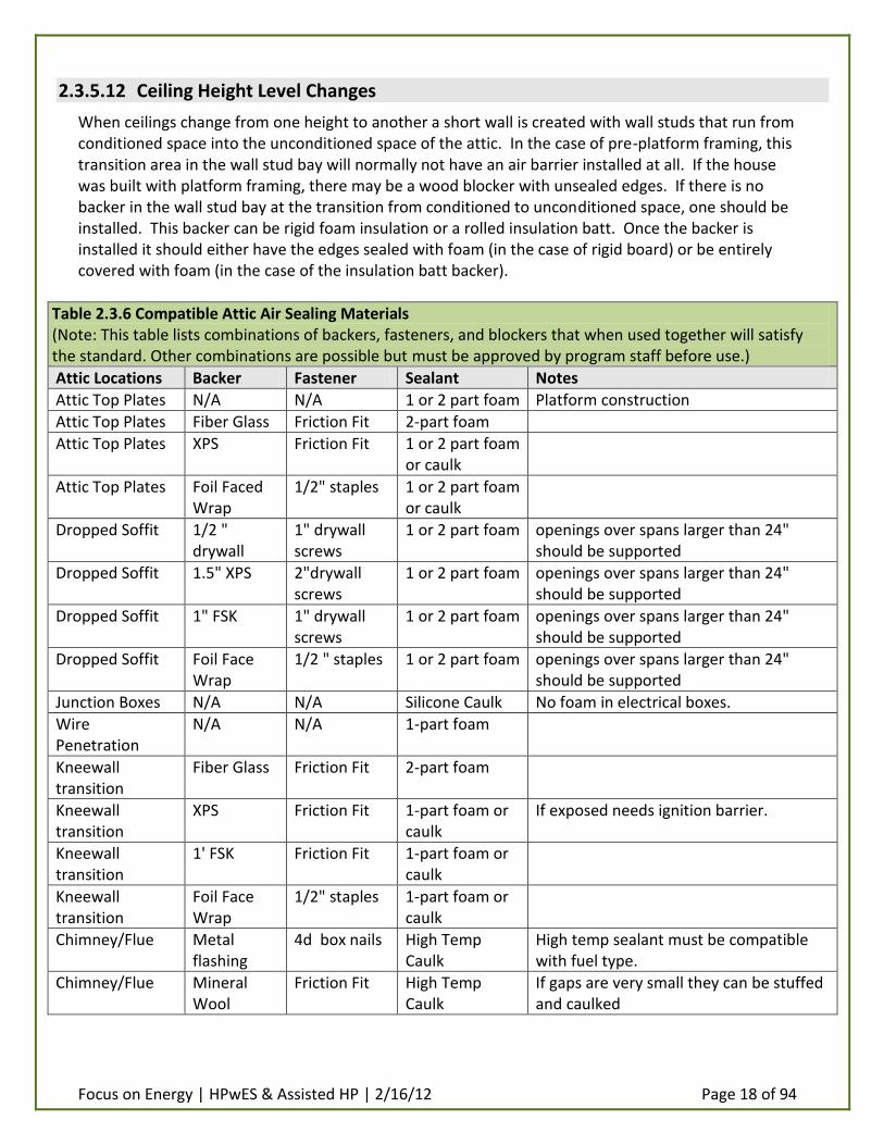
Table 2.3.6 Compatible Attic Air Sealing Materials (Note: This table lists combinations of backers, fasteners, and blockers that when used together will satisfy the standard. Other combinations are possible but must be approved by program staff before use.)
Attic Locations Backer Fastener Sealant Notes
Attic Top Plates N/A N/A 1 or 2 part foam Platform construction
Attic Top Plates Fiber Glass Friction Fit 2-part foam
Attic Top Plates XPS Friction Fit 1 or 2 part foam or caulk
Attic Top Plates Foil Faced Wrap
1/2" staples 1 or 2 part foam or caulk
Dropped Soffit 1/2 " drywall
1" drywall screws
1 or 2 part foam openings over spans larger than 24" should be supported
Dropped Soffit 1.5" XPS 2"drywall screws
1 or 2 part foam openings over spans larger than 24" should be supported
Dropped Soffit 1" FSK 1" drywall screws
1 or 2 part foam openings over spans larger than 24" should be supported
Dropped Soffit Foil Face Wrap
1/2 " staples 1 or 2 part foam openings over spans larger than 24" should be supported
Junction Boxes N/A N/A Silicone Caulk No foam in electrical boxes.
Wire Penetration
N/A N/A 1-part foam
Kneewall transition
Fiber Glass Friction Fit 2-part foam
Kneewall transition
XPS Friction Fit 1-part foam or caulk
If exposed needs ignition barrier.
Kneewall transition
1' FSK Friction Fit 1-part foam or caulk
Kneewall transition
Foil Face Wrap
1/2" staples 1-part foam or caulk
Chimney/Flue Metal flashing
4d box nails High Temp Caulk
High temp sealant must be compatible with fuel type.
Chimney/Flue Mineral Wool
Friction Fit High Temp Caulk
If gaps are very small they can be stuffed and caulked

Focus on Energy | HPwES & Assisted HP | 2/16/12 Page 19 of 94
Recessed Lights Drywall/XPS Tape 1-part foam or caulk
Drywall or XPS on the sides, drywall on top. Taped until foamed.
Open Chases Drywall 1" drywall screws
1 or 2 part foam openings over spans larger than 24" should be supported
Open Chases 1.5" XPS 2"drywall screws
1 or 2 part foam openings over spans larger than 24" should be supported
Open Chases 1" FSK 1" drywall screws
1 or 2 part foam openings over spans larger than 24" should be supported
Open Chases Foil Faced Wrap
1/2" staples 1 or 2 part foam openings over spans larger than 24" should be supported
Wet Wall Top Plates
XPS Friction Fit 1 or 2-part foam or caulk
backer must be moisture resistant
Wet Wall Top Plates
1" FSK Friction Fit 1 or 2-part foam or caulk
backer must be moisture resistant
Wet Wall Top Plates
Foil Faced Wrap
1/2" staples 1 or 2-part foam or caulk
backer must be moisture resistant
2.4 Wall Air Sealing
2.4.1 General
The following are general requirements for wall air sealing: 1. Sealant materials shall be compatible with the wall assembly materials and should allow normal
movement due to changes in temperature, humidity and air pressure variations. 2. Sealant materials shall be in a matching color to the substrate, or be paintable. 3. Sealants shall be installed in a manner that continues the function of the drainage plane. Do
not install sealants in a manner that will hold water in the wall assembly. 4. When insulation is used as part of the air barrier system, the installation shall be an air tight
material or meet the minimum density requirements for the material (See Section 2.3 Insulation Upgrades)
5. When membranes or films are used as air barrier system components, the entire perimeter of the material must be air sealed.
6. Windows, doors, and skylights should be integrated into the wall air barrier system. Seal the portion of the window, door, or skylight that is the air barrier component of the opening assembly to the air barrier component of the wall assembly, not the exterior siding or trim.
7. Mechanical penetrations shall be sealed to the air barrier component of the wall assembly, not the exterior siding or trim
2.4.2 Locations and Use
All structural and mechanical penetrations should be air sealed. As appropriate, windows will be caulked along the full perimeter of the interior or exterior; including sill area, side stops, apron, and casings. As appropriate, doors will be caulked along the interior or exterior casings and door jambs/stops.

Focus on Energy | HPwES & Assisted HP | 2/16/12 Page 20 of 94
2.4.2.1 Scoring
See the Living Space Air Sealing section of Appendix A for the list of tasks that will be considered part of thoroughly sealing the walls.
2.4.3 Material Standards
Wall air sealing materials can be broken into three different materials: Backers, Sealants, and Dense Pack Insulations.
2.4.3.1 Approved Backers
Backers are materials used to bridge openings that cannot be closed by sealants. Following is the list of approved backers for use when air sealing walls.
1. Fireproof Backers: a. Metal Flashing b. Mineral Wool
2. Fire-resistant Backers: a. Thermax b. Wall Board
3. Moisture-permeable Backers: a. Wall Board (unpainted) b. Building Wrap
4. Other Backers: a. 6-mil Polyethylene b. Radiant Bubble Wrap c. Plywood/OSB d. Thermo-Ply e. Structural insulated sheathing f. Foam Backer Rod
2.4.3.2 Approved Sealants
Sealants are any material applied to the existing wall air barrier or the installed backer that forms an air tight seal. Following is the list of approved sealants for use when air sealing walls.
1. Fireproof Sealants: a. Non-combustible fire rated caulk meeting ASTM E 136 b. Silicone high temp RTV on gas vents to 500 degrees Fahrenheit meeting ASTM C920
2. Non-Fireproof Sealants: a. 1-part urethane foam b. 1-part urethane fire block foam rated for sealing gaps in wood framing c. 2-part urethane foam kits d. Siliconized latex sealants meeting ASTM C834 e. Silicone urethane and other elastomeric sealants meeting ASTM C920

Focus on Energy | HPwES & Assisted HP | 2/16/12 Page 21 of 94
2.4.3.3 Dense Pack Insulations
Fibrous insulations blown into an enclosed cavity at a specified density can greatly reduce air flow through the cavity and can be considered a form of air sealing. The two most widely used materials for this application are cellulose and glass wool (fiber glass). Other materials that can be dense packed are mineral wool and rock wool. These materials and their required installed density can be assessed and approved upon request by a contractor.
2.4.4 Installation Standards
Air sealing the exterior walls can be broken into distinct parts. There is the combination of air sealing and insulation embodied in dense packing. There are heat sources that must be dealt with using fire proof materials and methods. There are seals made in areas that must resist moisture intrusion or allow vapor to escape when necessary. Finally, there are just penetrations through the walls that can be dealt with using “other” backers and non-specialized sealants.
2.4.4.1 Dense Pack Insulation
Walls with no existing insulation and empty cavities may be effectively air sealed by filling the wall cavity with densely packed fibrous insulations. (See Section 2.14 Wall Insulation.)
2.4.4.2 Heat Sources
Any penetrations through exterior walls that are considered a heat source (stove pipes, range hoods etc) must be sealed using fireproof materials. If the gap between the existing wall air barrier and the venting system cannot be bridged by sealants alone, the gap may be bridged with metal flashing and sealed with furnace cement meeting ASTM E136. An alternative method is to stuff the gap with mineral wool as a backer (and insulation) and seal the mineral wool with a fire-rated furnace cement meeting ASTM E136. If the gap is small enough to bridge with sealant alone it should be sealed with a fire-rated furnace cement meeting ASTM E136.
2.4.4.3 Moisture Resistant Seals
Air sealing of exterior walls in some locations may require the use of a material that is a class I vapor retarder. Such locations could be Bathrooms, Kitchens or other areas of high moisture concentration. When sealing out moisture is a consideration and the opening in the air barrier is too large to close with sealant, the opening should be sealed with one of the following: For interior sealing that is meant to retard vapor diffusion, XPS, painted wallboard, and polyethylene are acceptable materials. For exterior sealing meant to stop bulk moisture intrusion metal flashing, building wrap, polyethylene, and XPS are acceptable materials. Once the backer is selected based on location, suitability, and appearance a compatible sealant must be matched to the location and finished appearance requirements. Acceptable interior sealants are siliconized latex sealants meeting ASTM C384, silicone caulk meeting ASTMC920, 1-part urethane foam, and duct mastic. Suitable exterior sealants are siliconized latex sealants meeting C384 or silicone caulk meeting ASTM C920.
2.4.4.4 Other Wall Penetrations
When sealing interior wall penetrations that are not heat sources or areas of high moisture concentrations the choice of backer on large openings should be chosen based on two criteria:

Focus on Energy | HPwES & Assisted HP | 2/16/12 Page 22 of 94
Compatibility with the surrounding finish and fire resistance. Where visible or exposed to the living space, wallboard should be the material of choice as a backer due to its classification as a thermal barrier and its ability to be finished easily. Sealants in visible areas should be limited to either low sheen clear caulks or paintable caulks where applicable. 1-part foam can be used if it will then be covered by insulation or some form of ignition barrier.
2.4.4.5 Seal Baseboards
If a room is not carpeted, the baseboard can be sealed by caulking the seam between the baseboard molding and the floor and the baseboard molding and the drywall.
2.4.4.6 Window and Door Trim Sealed
The trim around windows and doors can be sealed using caulk at the seam between the window trim and the window frame and the seam between the window trim and the drywall.
2.4.4.7 Plumbing Penetrations Sealed
The area where plumbing pipes pass through walls can be sealed with caulk if the gap is less than ¼”, with 1-part foam if the gap is less than 1” or with an approved backer and 1-part foam or caulk if the gap is greater than 1”.
2.4.4.8 HVAC Boot to Subfloor/Drywall Sealed
The area where an HVAC supply or return boot penetrates the subfloor or drywall on a wall or ceiling can be sealed with duct mastic or caulk if the gap is less than ¼”. If the gap is greater than ¼” a backer must be used and then sealed with mastic.
2.4.4.9 Interior Sheathing Voids Repaired
Holes and gaps in the interior sheathing should be repaired with a material similar to the surrounding materials. These repairs should be discussed with the homeowner prior to beginning the repair to get approval of material and sealing methods.
2.4.4.10 Garage Door Weather Stripped & Swept
The door that separates occupied space from an attached garage will always be weather stripped. See section 2.6 for approved methods and materials.
2.4.4.11 Exterior Doors Weather Stripped & Swept
Doors between conditioned space and unconditioned space may be weather stripped and have a door sweep installed if the customer requests specifically. See Section 2.6 for approved methods and materials.
Table 2.4.5 Compatible Wall Air Sealing Materials (Note: This table lists combinations of backers, fasteners, and blockers that when used together will satisfy the standard. Other combinations are possible but must be approved by program staff before use.)
Wall Locations Backer Fastener Sealant Notes
Wall Cavities N/A N/A Cellulose Dense pack cellulose to 3.5+ lbs/cu. ft.

Focus on Energy | HPwES & Assisted HP | 2/16/12 Page 23 of 94
Wall Cavities N/A N/A Fiber Glass Dense pack fiber glass to 2.2+ lbs/cu. ft.
Wall Cavities N/A N/A Spray Foam See Appendices B,C,D for installation specifications
Heat Sources Metal Flashing
4d box nails High Temp Caulk
Use compatible caulk and fuel combination.
Moisture Resistant Interior
Drywall/Paint 1" drywall screws
see notes if finished look use joint compound, if not use 1-part foam
Moisture Resistant Interior
1.5" XPS 2" drywall screws
1-part foam or caulk
Not for finished areas
Moisture Resistant Interior
6 mil polyethylene
1/2" staples 1-part foam or caulk
Not for finished areas. "Tu-Tuff" or similar thinner sheeting may be substituted.
Moisture Resistant Interior
foil faced wrap
1/2" staples 1-part foam or caulk
Not for finished areas
Moisture Resistant Exterior
Metal Flashing
4d box nails silicone caulk
Moisture Resistant Exterior
Building Wrap 1/2" staples Sheathing Tape sealant must be protected from exterior exposure immediately
Moisture Resistant Exterior
Rigid Insulation
Screws Sheathing Tape sealant must be protected from exterior exposure immediately
Moisture Resistant Exterior
polyethylene 1/2" staples Sheathing Tape sealant must be protected from exterior exposure immediately
Other Openings 1/2" drywall 1" drywall screws
see notes finished look use joint compound, if not use 1-part foam. 1st choice-finish & fire rating
2.5 Window Weather-stripping
2.5.1 Locations and Use
Window weather-stripping will only be installed where it does not have the potential to affect window performance and where normal operation of the window will not cause the weather-stripping to be torn out. Note that the use of weather-stripping on windows and doors is governed by the Air Sealing installation standards above. The weather-stripping will not interfere with the smooth operation of the window
2.5.1.1 Scoring
See the Living Space Air Sealing section of Appendix A for the list of tasks that will be considered part of thoroughly weather stripping the windows and doors.
2.5.1.2 Window Weight Treatment
There are two separate window weight treatment techniques. Which technique is chosen is based on what treatment the window is undergoing. If the window is being weather-stripped only, then pulley

Focus on Energy | HPwES & Assisted HP | 2/16/12 Page 24 of 94
seals can be installed to slow air leakage through the pulley openings. If the window is being replaced, the window weight cavities will be accessed through the lower sash channel access panel. The ropes or chains that the weights hang on will be cut and removed along with the weights themselves. The pulleys should be removed from the upper sash channels and the opening covered with duct tape. The window weight cavities should now be dense packed using a fill tube and entering from the lower sash access panel. Re-install the access panels in the lower sash channels.
2.5.2 Material Standards
V-Seal type or equivalent vinyl weather-stripping with a deflection range of at least ¼" will be used. Materials must remain pliant in cold weather.
2.5.3 Installation Standards
All weather-stripping will be permanently installed with fasteners (tacks, staples, brads, etc.) and will make positive contact between surfaces to prevent air leakage. The weather-stripping will form an airtight seal when the window is closed and latched. A small bead of caulk will be applied as necessary to prevent air leakage behind the weather-stripping. Weather-stripping should be installed on any sash, meeting rail or sill surface that leaks air as long as placement does not interfere with the smooth operation of the window.
1. “Three-sided” LOWER sash channels, & sill; or, if window has spring loaded channels: top, bottom and meeting rail.
2. “Four-sided:” LOWER sash channels, meeting rail & sill.
2.6 Door Weather-stripping
2.6.1 Location and Use
Weather-stripping of doors between conditioned and unconditioned (or semi-conditioned) space will be performed if the customer specifically requests a door be treated; this includes doors to unconditioned basements and attic spaces. Doors connecting the house to an attached garage will always be weather-stripped.
2.6.1.1 Scoring
See the Living Space Air Sealing section of Appendix A for the list of tasks that will be considered part of thoroughly weather-stripping the doors.
2.6.2 Material Standards
2.6.2.1 Interior doors
"Q-lon" with either wood or steel carrier preferred, Q-lon strips allowed.
2.6.2.2 Exterior doors
Schlegel "Q-lon with carrier" (preferred), Porta Seal (I-D17), or equivalent.
2.6.2.3 Door sweeps

Focus on Energy | HPwES & Assisted HP | 2/16/12 Page 25 of 94
Door sweeps will be aluminum & vinyl, Dennis 905 (non-retracting), Pemko P307-AV (non-retracting) or equivalent.
2.6.2.4 Other
Weather-stripping will have a deflection range of at least 1/4". Weather-stripping will remain pliant in cold weather.
2.6.3 Installation Standards
1. All weather-stripping will be permanently installed with fasteners (tacks, staples, brads, etc.) and will make positive contact between surfaces to prevent air leakage.
2. The weather-stripping will form an airtight seal when the door is closed. A small bead of caulk will be applied as necessary to prevent air leakage behind the weather-stripping.
3. The weather-stripping will not interfere with the smooth operation of the door. 4. One of two types of sweeps will be used on exterior doors. Which sweep will be used will
depend on frequency of door usage. Doors that have high usage will be swept with a spring loaded sweep that will only engage and contact the floor when the door is closed. Low use doors can have either the spring loaded sweep or a non-retracting sweep that always makes contact with the floor.
5. After the weather-stripping is installed the door will be tested for ease of use. It should not be necessary to slam or exert excessive force on the door for the lock set to engage.
6. In addition to weather-stripping of doors and windows it may sometimes be necessary to install window sash locks, eye hooks, barrel bolts, etc. to make the installed weather stripping engage effectively.
2.7 Conditioned Basement Air Sealing
2.7.1 General
Basements are spaces that are primarily below grade. Basements are considered to be conditioned spaces in this section of the Standards. See Crawlspace & Unconditioned Basement Sealing for unconditioned basements and crawlspaces.
2.7.2 Heat Sources
The following penetrations from the basement to the exterior or the basement to the conditioned space are considered heat sources: Flue pipes from heating or DHW systems, flue pipes from solid fuel burning appliances, dryer vent pipe, or Kitchen exhaust vent pipe.
2.7.3 Locations and Use
The following basement locations must be airsealed: 1. Mechanical Chases and Other Large Openings 2. Rim Joists & Sills 3. Water Pipes 4. Basement Windows: Basement windows in older homes can be a significant source of low
infiltration into a home. 5. Dryer Vents

Focus on Energy | HPwES & Assisted HP | 2/16/12 Page 26 of 94
6. Plumbing Penetrations 7. Small openings between the basement and conditioned basement and conditioned or exterior
spaces
2.7.3.1 Scoring
See the Basement Air Sealing section of Appendix A for the list of tasks that will be considered part of thoroughly sealing the basement.
2.7.4 Material Standards
Basement air sealing materials will have different requirements based on the potential for high relative humidity in the space. Organic materials that support mold growth or materials that lose their rigidity after absorbing moisture should not be used. In addition to these requirements, backer materials that are used in the basement will need to either be fire-resistant or have an ignition barrier.
2.7.4.1 Approved Backers
Materials that do not need an ignition barrier: 1. Thermax rigid foam board 2. Metal Flashing 3. Mineral Wool 4. Polyethylene 5. Foil Bubble Wrap
Approved backer materials that do need an ignition barrier: 1. Rigid Foam Board (except Thermax)
2.7.4.2 Approved Sealants
Sealants that do not need an ignition barrier: 1. 1-part foam 2. Siliconized latex sealants meeting ASTM C834 3. Silicone urethane sealants meeting ASTM C920 4. Water based duct mastic meeting UL181A, UL181B-M 5. 2-part foam used as a sealant in the basement space will require an ignition barrier.
2.7.5 Installation Standards
The following installation instructions for basement air sealing locations detail the most common acceptable materials and practices.
2.7.5.1 Heat Sources
If the gap around heat sources is too great for sealant alone, the gap will be closed with metal flashing mechanically fastened to surrounding framing. If the appliance burns solid fuel or oil, the edges and gaps will be sealed using fire-rated caulk meeting ASTM E136. If the appliance burns natural gas or propane, the edges and seams will be sealed with high temperature silicone RTV meeting ASTM C920.

Focus on Energy | HPwES & Assisted HP | 2/16/12 Page 27 of 94
2.7.5.2 Mechanical Chases and Other Large Openings
Mechanical Chases and Other Large Openings: Large openings between the basement and the conditioned space or the exterior will need to be backed with a fire resistant material that does not support mold growth. For this reason, materials such as wall board or other paper based products are not allowed. Further, if the opening is between the basement and the conditioned space, then the material should also be a class 1 vapor retarder. Acceptable materials for closing large gaps would be Thermax, mineral wool, metal flashing or polyethylene. Materials such as XPS or other foil faced foam boards are acceptable if they will be either covered with insulation after installation or treated with an ignition barrier. The rigid material should be cut to fit over the opening with at least an inch of overlap where possible. The backer material should be fastened into place with mechanical fasteners (screws, staples etc). Once the backer is secured firmly into place, the edges should be sealed using caulk or 1-part foam.
2.7.5.3 Rim Joists & Sills
Rim joists and sills may be sealed with one of several different methods. It can be: 1. Sealed with 2-part foam that is either rated for exposure in conditioned space or covered with
an ignition barrier after installation. In this application the foam can be extended from the subfloor to the junction of the foundation and the sill plate. In areas where termite pressure exists, code may require an inspection break between the foam and the bottom of the sill. If there is a termite inspection break, the seam between the foundation and the bottom of the sill must be sealed using silicone caulk.
2. The rim joist can be sealed by cutting blocks of Thermax to fit in the rim joist area and sealing the edges with caulk or 1-part foam. In this application the sill to foundation seam and the seam between the two sill plates will also need to be caulked.
3. Caulk can be used to seal the seams in the framing where the rim joist and the sill and the rim joist and the floor joists meet. The rim joist can then be insulated with a section of unfaced glass fiber batt cut to fit. In this application the sill to foundation seam and the seam between the two sill plates will also need to be caulked.
2.7.5.4 Water Pipes
In spaces where pipes are at risk, the perimeter of the basement should be sealed tightly using one of the methods described in Section 2.7.5.3.
2.7.5.5 Basement Windows
Gaps in the frame and joints between the frame and the surrounding air barrier that are smaller than ¼ inch should be sealed with caulk. Larger gaps should be backed by backer rod and the seams caulked.
2.7.5.6 Dryer Vents
Dryer vents shall be treated as a heat source. If the gap between the dryer vent and the building surface is less than ¼ inch it can be sealed with high temperature silicone for gas vents meeting ASTM C920. If there is a gap too wide to be bridged by sealant alone, the gap should be sealed using either

Focus on Energy | HPwES & Assisted HP | 2/16/12 Page 28 of 94
metal flashing or mineral wool. The edges and seams should then be sealed with high temperature silicone for gas vents meeting ASTM C920.
2.7.5.7 Plumbing Penetrations
If the gap between the pipe wall and the subfloor is less than ¼ inch the gap may be sealed using caulk. If the gap is between ¼ inch and 1 inch it can be sealed using 1-part foam. If the gap is greater than 1 inch it must be bridged using a moisture-resistant, fire-resistant material. Thermax, metal flashing, OSB, or plywood is an acceptable material for this application. Once the gap is closed, the edges and seams should be sealed with either caulk or 1-part foam.
2.7.5.8 Small Openings Between the Basement and Conditioned or Exterior Spaces
Small openings should be sealed using a fire-rated sealant. This can be a 1-part foam product or a fire-rated caulk.
2.8 Crawlspace & Unconditioned Basement Air Sealing
2.8.1 General
Crawl spaces will use the same standards as Basements above, with the following exceptions: 1. Code compliance: When working in crawls spaces all applicable national, state, and local codes
regarding vapor retarders, ventilation, and ignition barriers (based on use type) will be followed.
2. Access considerations: When specifying energy upgrades in a crawl space auditors should keep access restrictions and ease of installation in mind when specifying methods and materials. (e.g., sheet goods might not fit into the space.)
3. Use the appropriate safety measures when crawl spaces qualify as confined spaces.
2.8.2 Locations and Use
See Section 2.7.3
2.8.3 Material Standards
See Section 2.7.4
2.8.4 Installation Standards
See Section 2.7.5
Table 2.8.5 Compatible Crawlspace & Unconditioned Basement Air Sealing Materials (Note: This table lists combinations of backers, fasteners, and blockers that when used together will satisfy the standard. Other combinations are possible but must be approved by program staff before use.)
Crawlspace & Basement Locations
Backer Fastener Sealant Notes
Heat Sources Metal Flashing
4d Box nails High Temp Sealant
Use compatible sealant and fuel combination.

Focus on Energy | HPwES & Assisted HP | 2/16/12 Page 29 of 94
Heat Sources Mineral Wool
Friction Fit High Temp Sealant
If gaps are 1/4" or less stuff and seal.
Mechanical Chases
1" Thermax 2" drywall screws
1 or 2 part foam or caulk
Use Thermax, not any other type of rigid foil faced board.
Mechanical Chases
Metal Flashing
4d box nails 1 or 2 part foam or caulk
Mechanical Chases
Polyethylene 1/2" staples 1 or 2 part foam or caulk
Mechanical Chases
1 or 1.5" XPS 2" drywall screws
1 or 2 part foam or caulk
Must have an ignition barrier if not covered by insulation.
Mechanical Chases
Rigid Insulations
2" drywall screws
1 or 2 part foam or caulk
Any rigid board insulation other than Thermax must have an ignition barrier if exposed.
Mechanical Chases
1" FSK 2" drywall screws
1 or 2 part foam or caulk
Mechanical Chases
Foil Face Wrap
1/2" staples 1 or 2 part foam or caulk
Large Openings See Mech Chases.
Rim and Band N/A N/A Spray Foam Spray foam must either be rated for exposure or have an ignition barrier.
Rim and Band Rigid Insulations
Friction Fit 1-part foam or caulk
Rigid insulation must be rated for exposure or have an ignition barrier.
Rim and Band N/A N/A 1-part foam or caulk
The framing junctions can be caulked or foamed and batt insulation added.
Pipe Penetration
Fiber Glass Friction Fit 1-part foam for gaps greater than 1"
Pipe Penetration
Foil Face Wrap
1/2" staples 1-part foam or caulk
for gaps greater than 1"
Pipe Penetration
N/A N/A 1-part foam for gaps between 1/4" and 1".
Pipe Penetration
N/A N/A caulk for gaps 1/4" or less
Windows/Doors Backer Rod Friction Fit caulk for gaps more than 1/4"
Windows/Doors N/A N/A caulk for gaps less than 1/4"
Windows/Doors N/A N/A 1-part foam gaps between 1/4" and 1". Care must be taken during installation to avoid over filling
Dryer Vent See Heat Sources

Focus on Energy | HPwES & Assisted HP | 2/16/12 Page 30 of 94
2.9 Kneewall Attic Air Sealing
2.9.1 General
2.9.1.1 Roof vs. Wall and Floor
A knee wall attic can be air sealed one of two ways. It can be sealed following the line of the roof rafters which will bring the knee wall attic space inside the conditioned area. The alternative would be to follow the knee wall itself from the sloped ceiling to the attic floor and then across the knee wall attic floor to the exterior wall top plate. This alternative would keep the knee wall attic as unconditioned attic space.
2.9.1.2 Vapor Permeable Air Barrier on Knee-walls
If the knee wall attic is air sealed as unconditioned attic space, this space will have to be ventilated according to state and local codes. Ventilating this space will make the knee wall insulation susceptible to wind washing. Therefore, a vapor permeable air barrier will need to be installed on the attic side of the knee wall to create a six sided wall cavity that will protect the installed insulation from wind washing.
2.9.2 Locations and Use
Knee wall or other side-attic areas, including rim joist areas under single-story shed roof, gambrel, garage, or other floor framing open into vented or unconditioned attic areas. If some areas are inaccessible, strategic dense-pack insulation should be considered to slow or stop leakage.
2.9.2.1 Scoring
See the Attic Airsealing section of Appendix A for the list of tasks that will be considered part of thoroughly sealing the kneewall attic.
2.9.3 Material Standards
If the attic has been sealed along the knee wall and attic floor and has been pushed outside of the conditioned space, refer to Section 2.3.4 for acceptable air sealing materials for this space.
2.9.3.1 Air Barrier Aligns with Roof Rafters
This plane will need to be sealed with an air impermeable barrier. If the rafter bays are insulated with glass fiber or cellulose insulation, the following air barriers are acceptable:
1. Wallboard 2. Thermax 3. Plywood 4. OSB 5. Structural insulated sheathing 6. Polyethylene 7. Building wrap
If the rafter bays are insulated with spray foam the air barrier will need to be an ignition barrier also. Approved materials in this situation would be:

Focus on Energy | HPwES & Assisted HP | 2/16/12 Page 31 of 94
1. Wallboard 2. Thermax 3. 3/8 inch particle board
2.9.3.2 Air Barrier Aligns with Knee Wall and Attic Floor
If the air barrier aligns with the attic knee wall, the interior face of the knee wall will be the air barrier. The material used to seal the knee wall transition area will depend on access. If the knee wall attic floor is not decked, the following materials are acceptable for sealing the opening between the floor joist cavities:
1. Rigid foam board 2. Wallboard 3. Framing lumber 4. Structural insulated sheathing 5. Foil-faced bubble wrap
2.9.4 Installation Standards
2.9.4.1 Air Barrier Aligns with Roof Rafters
If the air barrier is going to align with the roof rafters and bring the knee wall attic inside the conditioned space, an air barrier material will need to be run from the top plate of the knee wall to the top plate of the exterior wall. This air barrier can be a rigid material like Thermax, wall board, or XPS (XPS will need an ignition barrier) or it could be polyethylene or building wrap. The air barrier will have to be mechanically fastened with screws for rigid materials or staples for flexible barriers. All seams and edges will be sealed with 1-part foam on rigid materials, 3M 8086 or equivalent tape on polyethylene or building wrap tape on building wrap. See Sections 2.17 and 2.18 for proper venting and wind wash protection of insulation before sealing this space.
2.9.4.2 Air Barrier Aligns with Knee Wall and Attic Floor
If the air barrier aligns with the attic knee wall, the interior face of the knee wall will be the air barrier. The seam where the shoe plate of the knee wall sits on the subfloor should be sealed with caulk. If the knee wall attic floor is not decked, rigid foam board may be used to seal the knee wall area. The foam board should be cut into sections and rigid fit under the interior edge of the shoe plate so that it aligns with the interior face of the knee wall. The seams between the foam board and the floor joists, ceiling, and subfloor should be sealed with 1-part foam or caulk. The foam board should be re-covered with either glass fiber or cellulose insulation for fire protection. If the attic knee wall floor is sheathed this area should be air sealed using dense pack insulation. In some cases it may be desirable to stop blown-in material from penetrating too far down a bay above the living space when dense packing. In this case a burlap “feedbag” may be used as an inflatable insert into the floor joist bay. This can be done by stuffing the bag through the drill hole while holding onto the opening of the feed bag. The fill tube can then be inserted into the feed bag and the feedbag “inflated” with blown in material until it fills the bay and forms a plug under the knee wall. The remainder of the bay can then be dense packed without fear of insulation entering areas where it is not intended. The top plate of the exterior wall and any penetrations through the attic knee wall floor should be treated as specified in Section 2.3.5.
Focus on Energy | HPwES & Assisted HP | 2/16/12 Page 32 of 94
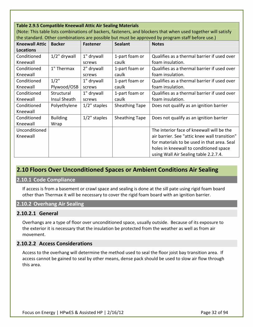
Table 2.9.5 Compatible Kneewall Attic Air Sealing Materials (Note: This table lists combinations of backers, fasteners, and blockers that when used together will satisfy the standard. Other combinations are possible but must be approved by program staff before use.)
Kneewall Attic Locations
Backer Fastener Sealant Notes
Conditioned Kneewall
1/2" drywall 1" drywall screws
1-part foam or caulk
Qualifies as a thermal barrier if used over foam insulation.
Conditioned Kneewall
1" Thermax 2" drywall screws
1-part foam or caulk
Qualifies as a thermal barrier if used over foam insulation.
Conditioned Kneewall
1/2" Plywood/OSB
1" drywall screws
1-part foam or caulk
Qualifies as a thermal barrier if used over foam insulation.
Conditioned Kneewall
Structural Insul Sheath
1" drywall screws
1-part foam or caulk
Qualifies as a thermal barrier if used over foam insulation.
Conditioned Kneewall
Polyethylene 1/2" staples Sheathing Tape Does not qualify as an ignition barrier
Conditioned Kneewall
Building Wrap
1/2" staples Sheathing Tape Does not qualify as an ignition barrier
Unconditioned Kneewall
The interior face of kneewall will be the air barrier. See "attic knee wall transition" for materials to be used in that area. Seal holes in kneewall to conditioned space using Wall Air Sealing table 2.2.7.4.
2.10 Floors Over Unconditioned Spaces or Ambient Conditions Air Sealing
2.10.1 Code Compliance
If access is from a basement or crawl space and sealing is done at the sill pate using rigid foam board other than Thermax it will be necessary to cover the rigid foam board with an ignition barrier.
2.10.2 Overhang Air Sealing
2.10.2.1 General
Overhangs are a type of floor over unconditioned space, usually outside. Because of its exposure to the exterior it is necessary that the insulation be protected from the weather as well as from air movement.
2.10.2.2 Access Considerations
Access to the overhang will determine the method used to seal the floor joist bay transition area. If access cannot be gained to seal by other means, dense pack should be used to slow air flow through this area.

Focus on Energy | HPwES & Assisted HP | 2/16/12 Page 33 of 94
2.10.2.3 Confined Spaces
Use special safety measures when crawl spaces qualify as confined spaces.
2.10.2.4 Locations and Use
2.10.2.4.1 SCORING
See the Basement/Crawlspace Air Sealing (Incl. Frame Floors Over Ambient) section of Appendix A for the list of tasks that will be considered part of thoroughly sealing an overhang.
2.10.2.5 Material Standards
The following materials are acceptable for use in the following overhang configurations: 1. Accessible from interior:
a. Backers: i. Thermax ii. Rolled batt iii. Foil-faced bubble wrap iv. Structural Insulated sheathing v. Framing lumber vi. Wallboard
2. Sealants: a. 1-part foam b. 2-part foam (with ignition barrier) c. Silicone caulk d. Duct mastic
3. Accessed from exterior: a. Backers: Same as Section a above. b. Sealants: Same as Section b above.
4. Exterior exposure: a. XPS b. 3/8 inch plywood c. 3.8 inch OSB
2.10.2.6 Installation Standards
Methods and materials for sealing overhangs will depend on existing conditions and access. For all overhangs in cold climates it will be necessary to inspect the floor joist bays to ensure that water pipes running through these areas will end up inside the conditioned area. Generally, this means that 75% of the insulation to be installed will be on the exterior side of the water pipes. If floor bays have ducts installed in them, then the ducts should be made air tight before pushing them outside with air sealing, especially before dense packing the joist bay. The following configurations will be sealed as specified below.
2.10.2.6.1 OVERHANG ACCESSIBLE FROM INTERIOR SPACE
Before sealing the transition area, the floor bay should be filled with insulation. The area where the floor joist crosses over the sill plate or exterior wall top plate should be sealed with an approved backer and the seams on all four sides of the backer sealed with 1-part foam or siliconized caulk. On

Focus on Energy | HPwES & Assisted HP | 2/16/12 Page 34 of 94
the exterior, the seam between the sheathing on the bottom surface of the floor joist and the surrounding siding/sheathing should be sealed using a silicone caulk rated for exterior use.
2.10.2.6.2 EXTERIOR OVERHANG WITH SHEATHING REMOVED FOR ACCESS OR NO SHEATHING
Seal the transition area using an approved backer. Seal the seams around the backer using 1-part foam or silicone caulk. Fill the overhang floor bays with batt insulation. If there is enough clearance at the bottom of the floor joist and the bottom of the siding/sheathing consider adding a layer of rigid foam board to break the thermal bridge before replacing or installing the overhang sheathing. Seal the overhang sheathing to the surrounding siding or sheathing using silicone caulk.
2.10.2.6.3 NO ACCESS TO THE OVERHANG FLOOR BAYS
This area can be dense packed to slow air flow. A thorough inspection of the floor joist bays should be made to ensure that there are no water pipes, ducts or recessed fixtures in the area to be dense packed. To stop the unwanted flow of blown insulation down the floor bays and into the conditioned space, the burlap “feedbag” method can be used. (See 2.9.4.2) The seam between the overhang sheathing and the exterior sheathing or siding should be sealed using silicone caulk.
2.10.3 Frame Floor Over Garage Air Sealing
2.10.3.1 Locations and Use
2.10.3.1.1 SCORING
See the Basement/Crawlspace Air Sealing (Incl. Frame Floors Over Ambient) section of Appendix A for the list of tasks that will be considered part of thoroughly sealing a frame floor over a garage.
2.10.3.2 Material Standards
The following materials are acceptable for use in frame floor configurations when sealing the ends of bays exposed to outside air movement or large openings between the garage and conditioned space above:
1. Accessible from adjacent knee wall attic: a. Backers:
i. Thermax ii. Rolled batt iii. Foil-faced bubble wrap iv. Structural Insulated sheathing v. Framing lumber vi. Wallboard
b. Sealants: i. 1-part foam ii. 2-part foam (with ignition barrier) iii. Silicone caulk iv. Duct mastic
2. Accessed from exterior: a. Backers: Same as Section a above. b. Sealants: Same as Section b above.

Focus on Energy | HPwES & Assisted HP | 2/16/12 Page 35 of 94
2.10.3.3 Installation Standards
Methods and materials for sealing frame floors over garages will depend on existing conditions and access. For all frame floors in cold climates it will be necessary to inspect the floor joist bays to ensure that water pipes running through these areas will end up inside the conditioned area. Generally, this means that 75% of the insulation to be installed will be on the exterior side of the water pipes. If floor bays have ducts installed in them, then the ducts should be made air tight before pushing them outside with air sealing, especially before dense packing the joist bay. The following configurations will be sealed as specified here:
2.10.3.3.1 GARAGE CEILING NOT SHEATHED HEAT SOURCES
If the gap around heat sources is too great for sealant alone, the gap will be closed with metal flashing mechanically fastened to surrounding framing. If the appliance burns solid fuel or oil, the edges and gaps will be sealed using fire-rated caulk meeting ASTM E136. If the appliance burns natural gas or propane, the edges and seams will be sealed with high temperature silicone RTV meeting ASTM C920.
2.10.3.3.2 MECHANICAL CHASES AND OTHER LARGE OPENINGS
Large openings between the garage and the conditioned space above will need to be backed with a fire resistant material. Acceptable materials for closing large gaps would be Thermax, plywood or OSB, drywall or structural insulated sheathing. Materials such as XPS or other foil faced foam boards are acceptable if they will be either covered with insulation after installation or treated with an ignition barrier. The rigid material should be cut to fit over the opening with at least an inch of overlap where possible. The backer material should be fastened into place with mechanical fasteners (screws, staples etc). Once the backer is secured firmly into place, the edges should be sealed using caulk or 1-part foam.
2.10.3.3.3 PLUMBING PENETRATIONS
If the gap between the pipe wall and the subfloor is less than ¼ inch the gap may be sealed using caulk. If the gap is between ¼ inch and 1 inch it can be sealed using 1-part foam. If the gap is greater than 1 inch it must be bridged using an approved backer. Thermax, metal flashing, OSB, or plywood is an acceptable material for this application. Once the gap is closed, the edges and seams should be sealed with either caulk or 1-part foam.
2.10.3.3.4 SMALL OPENINGS BETWEEN THE GARAGE AND CONDITIONED SPACES ABOVE
Small openings should be sealed using a fire-rated sealant. This can be a 1-part foam product or a fire-rated caulk.
2.10.3.3.5 RIM JOISTS & SILLS
The area where frame walls separate the garage from occupied space must be air sealed thoroughly to stop the exchange of air between the garage and the house. Rim joists and sills may be sealed with one of several different methods. It can be:
1. Sealed with 2-part foam that is either rated for exposure in conditioned space or covered with an ignition barrier after installation. In this application the foam can be extended from the subfloor to the top plate.
2. The rim joist can be sealed by cutting blocks of Thermax to fit in the rim joist area and sealing the edges with caulk or 1-part foam.

Focus on Energy | HPwES & Assisted HP | 2/16/12 Page 36 of 94
3. Caulk can be used to seal the seams in the framing where the rim joist and the sill and the rim joist and the floor joists meet. The rim joist can then be insulated with a section of unfaced glass fiber batt cut to fit.
2.10.3.3.6 GARAGE CEILING SHEATHED
This area can be dense packed to slow air flow. A thorough inspection of the floor joist bays should be made to locate water pipes, ducts or heat sources in the area to be dense packed. To stop the unwanted flow of blown insulation down the floor bays and into the conditioned space, the burlap “feedbag” method can be used. (See 2.9.4.2.)
1. Water pipes in area to be dense packed: See Section 2.10.4 2. Ducts located in area to be dense packed: See Section 2.10.4 3. Heat Sources located in area to be dense packed: This heat source located in an enclosed space
will need to have the bay that it is located in blocked with an approved backer with a clearance of at least three inches between the dam and the heat source. The backer will need to be made air tight with the surrounding materials to remove the chance that insulation dust under pressure could be forced within three inches of the heat source. If the heat source is close to one side of the bay and blown material in an adjacent bay is within three inches of the heat source, the adjacent bay must have a non-combustible insulation type (i.e. fiber glass or mineral wool) installed anywhere in that bay that is within three inches of the heat source.
2.11 All Insulation
2.11.1 General
The following applies to all insulation installed in the program: 1. Install attic, basement wall/ceiling, garage, and wall insulation upgrades according to program
specifications, based on customer work order. Program specified levels of insulation must be installed. All insulation upgrades in any location must conform to state and local codes.
2. Install strategic dense blown insulation in enclosed cavities, to control air leakage and increase insulation levels in attic, basement, and living space cavities.
3. Insulation upgrades will be specified by BPI Building Analyst certified technical assessors on a work order to the insulation subcontractor. It is the installing contractor’s responsibility to verify pre-installation requirements, measurements of insulated areas, and to install insulation products according to these specifications. In some cases the technical assessor may also be the insulation contractor. Any discrepancies should be brought to the attention of the program’s field supervisor before work commences.
4. Installation will meet or exceed the standards set forth in the Criteria for the Installation of Energy Conservation Measures publicized by the National Bureau of Standards, including, but not limited to the standards set forth below. Documentation of installed insulation levels, material or bag counts, and insulated area will be left at the electrical panel or when it is not possible to leave it at the electrical panel, with the customer according to Federal Trade Commission (FTC) rules.
2.11.2 Measurement of Areas
1. There are three locations from which components of a building can be measured: outside, in the living space, or in a buffer zone such as an attic or crawlspace. Measuring from the outside

Focus on Energy | HPwES & Assisted HP | 2/16/12 Page 37 of 94
is always preferred. When the building floor plan and the area to be insulated, such as the attic floor plan, are the same, exterior dimensions should be used.
2. Interior measurements from the living space (preferable) or from inside the attic/kneewall space (second option if living space measurements are inconvenient or not accessible) will be used for attic areas that do not match the building floor plan, such as knee-walls, slopes, cathedral ceilings, kneewall floors and attic flat areas that are smaller than the building floor plan. When interior measurements are used, then an additional foot will be added to each dimension to compensate for exterior wall thickness.
3. When taking measurements, round up to the next half-foot. If the dimension is between 24’ 1” and 24' 5", you should round up to 24' 6" (24.5) feet.
4. Changes in the methods used for measurements may be altered on a job-by-job basis, but must be specifically noted directly on the work order.
5. Measurements for wall insulation will be based on the gross wall area determined by the exterior perimeter multiplied by the interior wall height(s). One (1) extra foot of height will be added for band joist perimeter of floor system between two conditioned floors if the home is balloon framed. Basic windows and doors will be deducted from this area. Large sections which cannot be insulated, such as brick walls or fireplaces should be deducted and noted on insulation work orders.
6. If exterior dimensions cannot be taken for the building shell and interior dimensions are used, an additional two linear feet should be added to the perimeter before it is multiplied by the interior wall height.
2.11.3 Physical Properties
Insulation materials shall satisfy the requirements of the following national standards: 1. Batts - ASTM Standard C 665. 2. Loose fill (blown) cellulose - ASTM C 739. 3. Loose fill (blown) fiber glass - ASTM C764. 4. Preformed polystyrene boards - ASTM C-578. 5. Preformed polyurethane/polyisocyanurate boards - ASTM C 591.
2.12 Attic and Roof Slope Insulation
Before insulating the attic, contractor will ensure that all bypasses at chimneys, soil stacks, perimeter walls, dropped ceilings and any other penetrations through the attic floor, or at attic transitions (i.e. changes in ceiling height) have been sealed. Pressure differential testing and visual inspections will be used to ensure that all identifiable leakage has been addressed. Attic insulation shall not proceed until the area has been properly sealed and documentation is complete.
2.12.1 Locations and Use
2.12.1.1 Scoring
See the Attic Insulation section of Appendix A for the list of tasks that will be considered part of thoroughly insulating the attic and roof slopes.
2.12.2 Material Standards
Focus on Energy | HPwES & Assisted HP | 2/16/12 Page 38 of 94
Loose blown, batt and rigid foam board insulations in attic spaces shall meet all of the requirements listed in Section 2.12.3. Where the brand name Thermax is specified for rigid foam board, a foam board that is rated for exposure to conditioned areas without an ignition barrier must be used. Otherwise the foam board must have an ignition barrier as specified in Section R316.5.3 of the 2009 IRC. Area spray foams used in areas exposed to attic areas will also conform to Section R316.5.3 unless rated for exposure in conditioned spaces.
2.12.3 Installation Standards
2.12.3.1 Baffles
Baffles will be installed in the following areas before insulation work begins: 1. The end of each ceiling joist bay that connects to a soffit. When soffit vents are to be installed
or already exist, baffles will be installed in the space connected to the soffit vents in such a way that the top plate can be insulated. Where possible, a clearance of 1" from the top of the baffle to the underside of the roof sheathing will be provided in accordance with building code. Blocking will be permanent, mechanically fastened at sides and at bottom, and ensure the free movement of air through soffit vents into the attic, but not allow the air to "wind wash" the insulation and reduce its effectiveness. Wind washing is air movement through insulation which degrades insulation performance. The two most common areas where this occurs in an attic is at the eaves where ventilation air can pass through the edges of the insulation that abut the soffit area and on the back side of unprotected knee wall cavity insulation where, once again, ventilation air can move through wall cavity insulation. At the eaves, wind washing can be stopped by installing a rigid, air impermeable baffle that extends from the outer edge of the exterior wall top plate to within two inches of the roof sheathing and is attached to the joists on either side of the cavity that is being protected. Once this baffle is either installed by rigid fit or fastened with staples, any remaining gaps should be sealed with foam. It will be rigid enough to restrain loose-fill insulation from congesting the soffit vents at the eaves and obstructing ventilation. These baffles must extend above the final level of resulting insulation by at least four inches, so to be visible upon inspection. Pre-cut Styrofoam baffles are preferred.
2. When specified, ventilation chutes will be installed in each slope cavity before insulating. These will allow air to flow from soffit or kneewall area into peak. Baffles will be mechanically fastened at sides and at bottom and will be carefully fitted with insulation packed in place at the bottom to prevent wind intrusion into or under insulation.
3. Permanent baffles will be installed around all recessed light fixtures. A minimum clearance of 3" will be maintained from the light fixture to the baffle. For further guidance on treating recessed lights, refer to Section 1.2.6.
4. Permanent baffles or dams will also be installed around all attic hatch covers in the following manner: a. They will not interfere with the opening of the hatch cover b. When the hatch is opened, they will prevent loose-fill insulation from falling into the living
area. c. They will allow for easy access into attic for future inspection.

Focus on Energy | HPwES & Assisted HP | 2/16/12 Page 39 of 94
d. This damming may be accomplished by using unfaced fiberglass batts of greater thickness than the installed insulation placed around the perimeter of the hatch, or by using a framing lumber fixed in place around the hatch.
e. Insulation levels immediately surrounding the hatch will equal or exceed the R-value of the rest of the attic space.
2.12.3.2 Electric Radiant Strip Heating Elements
Blown-in or faced insulation will not be installed in contact with electric radiant strip heating elements. A minimum 3-inch thick un-faced mineral wool fiber batt will be installed first.
2.12.3.3 Doors & Hatchways
All doors and hatchways will be insulated with 2” of Thermax, as specified, glued to the door or hatch with a compatible adhesive, attached with screws and 1" minimum washers, and weather stripped. If any other rigid foam insulation material is used it will need to be covered by a thermal barrier that complies with ASTM E-84 recommendations. Mechanical fasteners will be used where necessary to ensure tight closure of weather-stripping. (See weather-stripping)
2.12.3.4 Bathroom Fans
All bathroom fans will be dammed using unfaced batts and vented through the roof with insulated ductwork. If roof penetrations are prohibited, an alternative route will be devised.
2.12.3.5 Access Openings
Where entry to the attic via pre-existing hatchway of access panel is not possible, access to attic areas will be gained from the exterior through roof or gable vent openings. If this is not feasible, then the following procedures will be used for access openings:
1. Surface Openings: existing wallboard will be cut halfway on two studs (preferably through a closet). Opening will be closed with the same type of materials flush with existing wall material and taped and covered with one coat of joint compound.
2. Plywood Openings: existing wall will be cut between two studs. Opening will be closed with ½" plywood (G1S/AC) with four (4) 1 1/2" x 8 flat head wood screws secured into studs, with heads countersunk or set flush with the plywood surface.
3. Finished Openings: existing ceilings will be cut. Opening will be headed off, and a 2 ½" casing will be installed around the rough opening. A 3/8" reveal will be allowed into opening to receive 1/2" plywood (G1S/AC) to complete opening. Plywood cover will be weather stripped and insulated. Casing will be mitered neatly.
2.12.3.6 Flooring
If homeowner so desires, when attic flooring is removed, it will be reinstalled and screwed securely back into place.
2.12.3.7 Open Blow Insulation
Loose fill blown in insulation will be installed according to manufacturer's specifications and recommended densities. All open blow attics will be installed to a level condition. Insulation in open blown areas will have minimum material count per manufacturer’s instructions, as follows: thickness

Focus on Energy | HPwES & Assisted HP | 2/16/12 Page 40 of 94
as specified in work order is average settled thickness. A cellulose table and example is provided below.
Inches on work order 3 4 5 6 7 8 9 10 11 12 13 14 15 16
Installed R-value 11 14 18 21 25 28 32 35 39 42 46 49 53 56
Example: Work order specifies 12" cellulose open blow. R-value from chart is R-42. Attic area is 1000 s.f. Look at chart on product bag, if chart says that installed R-42 = 60 bags for1,000 sq. ft, you need to install 60 bags. Minimum thickness specified on work order also applies.
1. Use depth charts provided by the manufacturer as a guide to specifying the number of inches to
be installed. The installer will need the depth estimate to monitor insulation installation amounts. The depth and desired r-value should be checked periodically to ensure that the projected number of bags for the desired density are being installed.
2. In attics with existing fiberglass batts, the batt that is in the last joist bay on any gable end or other perimeter configuration that runs perpendicular to strapping ends, will be removed. This space will be filled to capacity with blown-in insulation. In addition, existing batts will be pulled back from front and rear soffit plates approximately 12" during baffling. This area will be insulated to specifications with blown-in insulation.
3. Damming: Blown in insulation will need to be contained using damming at the following areas and listed clearances: Chimneys & double wall flues (3”), single wall flues (6”), Recessed lights or bath fans with heat lamps or lights (3”). Attic hatches or pulldown stairs, whole house fans, mechanical access walkways, air conditioner drip pans, and storage areas (no clearance required).
2.12.3.8 Dense Pack Insulation
1. Blown in insulation in restricted or dense packed applications shall be 3.5 lbs/cu. ft. for cellulose and 2.2 lbs/cu. ft. for blown fiber.
2. Unless the area is sealed by other means, dense pack insulation will be installed to a minimum density of 3.5 lb. /cu. Ft for cellulose or 2.2 lbs/cu. ft. for blown fiber beneath all sections of the knee-wall in the joist cavity. The cavity will be sufficiently packed and sealed to make it extremely difficult to force a fist through, or detect any air movement with infrared (IR) scan and blower door.
3. Closed slopes will need to be ventilated according to state and local codes. If they can be ventilated satisfactorily, the top and bottom opening of the slope should be sealed with a firmly rolled unfaced batt. The ceiling bay should then be dense packed to the required density for the material used. Under no circumstances should an air permeable insulation be compressed against the roof sheathing and dense pack insulation blown between the air permeable insulation and the interior sheathing.
4. Open slopes with netting will be ventilated to state and local codes before the netting is installed. Once the netting is in place the ceiling bays should be dense packed to the required density for the material being used. Under no circumstances should an air permeable insulation

Focus on Energy | HPwES & Assisted HP | 2/16/12 Page 41 of 94
be compressed against the roof sheathing and dense pack insulation blown between the air permeable insulation and the interior sheathing.
2.13 Wall Insulation
2.13.1 General
Combustion safety screening and/or testing is required before and after air sealing, which includes when greater than 25% of the exterior walls are densepacked. All test results must be recorded in the Combustion Safety section of EnergyMeasure Home.
2.13.2 Location and Use
2.13.2.1 Scoring
See the Wall Insulation section of Appendix A for the list of tasks that will be considered part of thoroughly insulating a wall.
2.13.3 Material Standards
Installed insulation materials will conform to the specifications listed in Section 2.3.2.1. Caulks used on exterior siding will be rated for at least 20 years. Pure silicone will generally be used in exterior applications, unless paintability is needed. Pure silicone will be used anywhere that sealants are needed between wood and metal, wood and concrete, or other materials with differential expansion as moisture and temperature vary, or where greater flexibility is needed. Siliconized acrylics will generally only be used in interior locations or where paintability is important. Only backer materials that are water proof will be used in exterior wall applications. These would include 6 mil polyethylene, closed cell foam backer rod, metal flashing at heat sources or extruded polystyrene. Exterior drill and plug repair on painted wood surfaces will require insertion of a wooden plug and DAP exterior vinyl spackling or equivalent. Drill and plug applications through drywall or plaster will require the use of a Styrofoam plug and joint compound.
2.13.4 Pre-Installation Requirements
2.13.4.1 Knob and Tube Wiring
Verify that knob and tube wiring has been replaced with approved wiring. Receive certification that existing knob and tube wiring is not live. (see section 1.2.3 for complete policy). Ensure that the moisture conditions detected in the structure during the course of the initial inspection are corrected prior to insulation of the sidewall cavities. This may be accomplished by one or more of the following techniques:
1. All cracks and holes will be thoroughly sealed through the interior wall surfaces in high moisture areas (kitchen, bathrooms, etc).
2. A vapor barrier may be installed, when possible, on the interior surface of the walls in bathrooms, kitchens, laundry rooms, and any other high moisture areas.
3. A vapor barrier floor covering, and possibly mechanical ventilation will be installed into high moisture crawlspace per specification.
4. Exterior structural flaws that admit rainwater into wall cavities will be corrected: repair gutter, downspout, drainage system, and seal gaps above door/window casings.

Focus on Energy | HPwES & Assisted HP | 2/16/12 Page 42 of 94
5. An adequate moisture control system will be installed in the house, including indoor mechanical ventilation (A.3) and passive attic ventilation (B.2.)
6. Clothes dryers will be vented to the outside. 7. The owners/occupants will be advised to lower their humidifier and/or to change lifestyle
practice, which contribute significantly to high humidity.
2.13.4.2 Moisture
Prior to starting a job, an interior and exterior inspection must be conducted to determine any potential problem areas. These problem areas must be identified and addressed prior to working on that area. Examples of some problem areas are recessed radiators, duct work in wall cavities, recessed bookshelves, stairways on exterior walls, loose or cracked plaster on walls, poor siding, etc. Check wall areas for valuables that should be removed prior to working on walls. The process and the work that is to be performed should be explained to the client. Any problem discovered should be discussed with a program field supervisor before commencing work. Ensure that all openings in sidewalls through which the insulation can escape to the interior or exterior
of the building are blocked as follows:
1. Missing interior wall surfaces will be covered with a compatible material (i.e., drywall) and sealed into place. Generally this will be done at owner’s expense prior to beginning work, unless other arrangements are specified. If such conditions are found and not noted on work order, contact a program field supervisor before proceeding.
2. Missing or damaged exterior siding on homes with incomplete or no subsiding will be replaced/repaired. Generally this will be done at owner’s expense prior to beginning work, unless other arrangements are specified. If such conditions are found and not noted on work order, contact a program field supervisor before proceeding.
3. Block all openings in sidewalls through which the insulation may escape. Seal all wall cavities, which open into a basement or crawlspace with un-faced fiberglass batts before wall insulation is installed. Also check for pipes that enter kitchen cabinets and block them as needed.
4. Wall cavities with no top plate and/or open at the sill plate will be blocked and sealed with air impermeable barrier, such as rigid polystyrene insulation.
5. Ensure insulating cavities will neither allow insulation to escape nor present a hazard to the occupant, installer or the home's structural/mechanical integrity, i.e., heat ducts, recessed lights, vent fans, electrical service entrances, etc.
2.13.4.3 Sidewall Openings
Ensure that all openings in sidewalls through which the insulation can escape to the interior or exterior of the building are blocked as follows:
1. Missing interior wall surfaces will be covered with a compatible material (i.e., drywall) and sealed into place. Generally this will be done at owner’s expense prior to beginning work, unless other arrangements are specified. If such conditions are found and not noted on work order, contact a CSG field supervisor before proceeding.
2. Missing or damaged exterior siding on homes with incomplete or no subsiding will be replaced/repaired. Generally this will be done at owner’s expense prior to beginning work,

Focus on Energy | HPwES & Assisted HP | 2/16/12 Page 43 of 94
unless other arrangements are specified. If such conditions are found and not noted on work order, contact a CSG field supervisor before proceeding.
3. Block all openings in sidewalls through which the insulation may escape. Seal all wall cavities, which open into a basement or crawlspace with un-faced fiberglass batts before wall insulation is installed. Also check for pipes that enter kitchen cabinets and block them as needed.
4. Wall cavities with no top plate and/or open at the sill plate will be blocked and sealed with air impermeable barrier, such as rigid polystyrene insulation.
2.13.4.4 Avoiding Hazards
Ensure insulating cavities will neither allow insulation to escape nor present a hazard to the occupant, installer or the home's structural/mechanical integrity, i.e., heat ducts, recessed lights, vent fans, electrical service entrances, etc.
2.13.4.5 Interior & Exterior Inspections
Prior to starting a job, an interior and exterior inspection must be conducted to determine any potential problem areas. These problem areas must be identified and addressed prior to working on that area. Examples of some problem areas are recessed radiators, duct work in wall cavities, recessed bookshelves, stairways on exterior walls, loose or cracked plaster on walls, poor siding, etc. Check wall areas for valuables that should be removed prior to working on walls. The process and the work that is to be performed should be explained to the client. Any problem discovered should be discussed with a CSG field supervisor before commencing work. For buildings with masonry exteriors, the contractor must confirm through visual observation that there is a barrier in the wall system that will prevent blown in insulation from coming into contact with the masonry. The purpose of this observation is to ensure that the insulation will not absorb moisture when the masonry gets wet. The visual observation can be with the naked eye or via boroscope, and should be done for each cavity that is being insulated. This barrier will typically be in the form of sheathing attached to a frame wall, but other systems that separate the insulation from the masonry are also acceptable.
2.13.4.6 Siding
Because the siding on a house is the most obvious indicator a homeowner will have regarding the quality of an insulation job, it is extremely important that the siding work is done properly. Contractors should always demonstrate to the homeowner how the siding will be removed and replaced before beginning work.
2.13.4.6.1 WOOD SHINGLE SIDING REMOVAL
1. Wood shingles should be removed with great care to minimize stray knife marks, splits, and broken shingles. A 45-degree bevel cut must be used when removing existing shingles. The bevel cut should be made at the butt of the shingle above, and should be as straight as possible. Use the butt of the shingle above as a guide.
2. Clapboards must also be removed using a 45-degree bevel cut. This cut must be made at the butt of the course above and should be as straight as possible. Do not follow the grain of the clapboard. The bevel cut should be as deep as possible to reduce the possibility of splits. A flat

Focus on Energy | HPwES & Assisted HP | 2/16/12 Page 44 of 94
bar should be used to pry the clapboard away from the house far enough to remove the nails from the butt of the clapboard.
3. Sometimes when removing clapboards, it is necessary to make a vertical cut and remove a portion of a clapboard. When this is done the vertical cut must be perpendicular (straight up and down from the butt) to the courses of clapboards. This cut must be all the way through the clapboard before prying the clapboard from the house.
2.13.4.6.2 VINYL SIDING REMOVAL
1. Vinyl siding must be removed using a "zip tool" to unlock the siding. After the siding is unlocked, the nails in the top of the siding course below can be removed and the siding will come off the house.
2. Great care should be used when working around windows, doors, inside and outside corners to reduce the possibility of breaking or chipping the J-channels and corner posts.
3. When removing siding, workers' hands should be clean so that the siding does not have hand- and fingerprints on it.
2.13.4.6.3 ALUMINUM SIDING REMOVAL
1. In most cases, aluminum siding must be removed using a "zip tool". Once the siding is unlocked follow the procedures for vinyl siding removal above.
2. In some cases, aluminum siding cannot be zipped off. When this occurs, call this to the attention of the program field supervisor for further instructions. Do not proceed with removal of siding if it varies from the normal procedure until the program approves a different technique.
3. To reduce the possibility of bending or denting aluminum siding, great care should be used when handling it, particularly in windy conditions.
2.13.4.6.4 ASBESTOS SIDING REMOVAL
1. Care must be taken not to disturb the siding material itself or cause dust or cracking, which may release asbestos fibers.
2. Single-nailed asbestos siding must be removed by removing the exposed nails at the butt of the shingle using "nippers" or straight diagonal cutters. By placing the cutter on the shingle and pressing against it, the nail head will be exposed and can be grabbed and removed. Once the nails are removed, the shingles will come off the house.
3. Double-nailed asbestos siding must be removed in the same manner as single-nailed. The only additional step is to remove the nails in the butt of the shingle above that go through the top of the shingle to be removed. The process for nail removal is the same as described above.
4. Blind-nailed asbestos siding presents a unique problem. Any exposed nails must be removed first, using the procedures previously mentioned. The blind nails covered by the butt of the shingle above must be cut-off before the shingle can be removed. To do this use a reciprocating saw (Sawz-all) with a thin hacksaw blade, to cut the heads of the blind nails. Once this is done, the shingle can be removed. If nails cannot be cut without damaging the siding or causing dust, stop work and call a program field supervisor before proceeding.
2.13.4.6.5 ASPHALT SHINGLE REMOVAL
1. Use straight diagonal cutters to remove exposed nails by pushing on the shingle around the nail head with the cutter blades.

Focus on Energy | HPwES & Assisted HP | 2/16/12 Page 45 of 94
2. Remove the nails on the bottom of the shingles directly above the shingle to be removed. 3. Carefully lift the bottom of the top shingle and locate the nails that are holding on the shingle
to be removed. Use a sharp chisel and a hammer to cut the heads off the nails. 4. Carefully remove the shingle and place to the side.
2.13.5 Installation Standards
2.13.5.1 Drill and Plug (D&P) Applications
All blown in wall insulation will be installed with minimum 2 1/8" holes. Locate entry holes in walls to permit complete filling of wall cavities. Exterior drill and plug applications must be done as neatly as possible. Be sure to use sharp drill bits designed to cleanly cut holes with no tear out or other surface damage, properly sized for the wooden plugs being used. Speed-bore bits should not be used for this application.
2.13.5.1.1 INTERIOR APPLICATIONS
1. Before beginning work on interior drill and plug applications the area to be worked on should be cleared of as much homeowner property as possible. Remaining large pieces of furniture etc should be covered with drop clothes and sealed tightly. The area to be drilled should be sealed tightly from the remainder of the house using polyethylene sheeting, extension poles and duct tape. When drilling interior walls the holes should be staggered horizontally to avoid drilling out the same row of lathe as this weakens the wall and can cause large sections to detach. It is recommended that two drills be used for the interior drill process. The first drill will be used to cut through the plaster and will be very dull. The second drill will be used on the same hole after the plaster has been cleared to cut cleanly through the lathe and minimize pulling and cracking.
2. An example of the drilled and plugged hole should be made in an inconspicuous place, and shown to the owner at the beginning of the job for approval.
2.13.5.1.2 EXTERIOR
1. When drilling holes through siding that cannot be removed, and that has no repeating reference marks, a line should be snapped (do not use waterproof cement chalk!) to keep the plugs level across the wall. Examples of this type of application are Texture 1-11, novelty siding, knotty pine siding, frieze boards, and any other sheathing type siding. Interior drill and plug applications would be attic stairway walls and exterior walls (when not done from the outside).
2. Holes should be drilled as neatly as possible through all siding and sheathing materials, including plaster and wallboard.
3. During the hole drilling process, cavities should be probed in FOUR directions (left, right, up, and down) to ensure stud and blocking locations are correctly identified and blind bays are not left un-insulated.
4. Do not leave holes in wall open overnight. Any holes must be plugged at the end of the day if work is not complete.

Focus on Energy | HPwES & Assisted HP | 2/16/12 Page 46 of 94
2.13.5.2 2-Hole Installation Method (Walls, Ceilings, Etc.)
1. A double-hole method preparation is mandatory for all drill and plug applications on exterior walls exceeding four (4) feet in height. See Installation Procedures below for requirements for hole preparation in all wall cavities.
2. Use of a fill tube to ensure consistent insulation coverage and density is required. Only one hole is required per cavity, if a fill tube is used, provided the tube is long enough to reach both ends of the cavity from the opening.
3. Use only equipment compatible with the insulation material used. Follow the manufacturer's recommendations for air pressure and density.
4. Keep a record of the number of bags used to insure the installed insulation conforms to the manufacturer's recommended coverage shown on the material label.
5. Using smoke devices to test dense-packing: To test density of installed insulation, dense pack one bay. Use the blower door to de-pressurize the house to 50 PA wrt outside and use a smoke puffer to generate smoke at the drill hole of the insulated cavity. If the smoke is drawn into the cavity, adjust the material and air settings on the insulation machine and re-blow the bay. Repeat the test until the smoke is not drawn into the cavity when the house is under pressure.
2.13.6 Post-Installation Requirements
2.13.6.1 General
1. Prior to reinstalling siding all holes opened in a wall must be covered or closed with one of the following: 15# felt paper stapled in place, wood, cork, Styrofoam plugs.
2. Repairing drainage planes: Before replacing the siding the existing drainage plane should be tied back into. This can be done using 15# felt paper or building wrap (don’t use building wrap with cedar shingles). Cut a four by four patch from the felt paper or wrap, slide the upper edge of the patch under the piece of siding above and staple into place over the plug at all four corners.
3. All types of siding must be reinstalled as close to its original condition as possible. One of the most important aspects of this procedure is to ensure that the siding is weather tight. Damaged siding must be replaced or repaired as needed. Clapboards and wood shingles that are split or broken as a result of removal or installation must be replaced with materials that match the original. The new siding must be primed white (pre-primed in inclement weather) on the front, back and both ends. If the owner provides the paint to match the building the contractor should apply it to all areas requiring touch up as a result of the removal work, weather permitting.
4. It is not acceptable to patch siding with materials that are not intended for exterior use, (i.e. plastic wood, spackle, joint compound). Patching of small areas must be done using a paintable siliconized acrylic caulking compound.
2.13.6.2 Reinstallation of Wood Shingles
1. After installation, the shingle should be reinstalled by tapping the butt lightly making sure the bevel cut is closed completely. Re-nail the shingle with at least two (2) four penny galvanized finish nails through the butt of the shingle.

Focus on Energy | HPwES & Assisted HP | 2/16/12 Page 47 of 94
2. When replacing damaged shingles with new shingles, make a bevel cut on the new shingle and install it according to the above procedure. If the bevel cut does not match properly, siliconized acrylic caulking compound must be used to seal this area.
2.13.6.3 Reinstallation of Wood Clapboards
1. After insulating, the clapboards should be reinstalled by tapping the butt lightly, making sure the bevel cut is closed completely. Nail the clapboard with four penny galvanized finish nails through the butt of the clapboard. When nailing the clapboard do not nail into the existing nail holes. These holes must be filled with a paintable siliconized acrylic caulking compound and left flush with the clapboard.
2. When replacing damaged clapboards with new clapboards, do not simply cut the new clapboard. Remove the top of the clapboard that was originally cut including the nails through the butt of the clapboard above. Once this is done, install the entire new clapboard and nail in the butt of both the new clapboard and the clapboard above. Seal old nail holes as mentioned above.
3. Prime, the front, back, and both ends of the new clapboard. (In inclement weather, it should be pre-primed.)
2.13.6.4 Reinstallation of Vinyl Siding
1. Reinstall the panels that were removed. Lock the bottom of the panel that was removed, and nail the top of that panel in the nailing strip using roofing nails. Do not nail the panels tight; the nail must be just loose enough in the nailing slot to allow for expansion and contraction of the vinyl due to changes in weather.
2. Punch slots with a slot tool where nailing is required and no factory-installed slot is available. 3. Once this is completed, lock the butt of the panel above with the top of the panel that was
removed. 4. Do not face nail vinyl siding.
2.13.6.5 Reinstallation of Aluminum Siding
1. Reinstall the panels that were removed. Lock the bottom of the panel that was removed, and nail the top of that panel in the nailing strip using aluminum roofing nails. Do not nail the panels tight; the nail must be just loose enough in the nailing slot to allow for expansion and contraction of the aluminum due to changes in weather.
2. Punch slots with a slot tool where nailing is required and no factory-installed slot is available. 3. Once this is completed, lock the butt of the panel above with the top of the panel that was
removed. If necessary, nail six penny galvanized finish nails through the weep holes to secure the panels.
4. Do not face nail aluminum siding.
2.13.6.6 Reinstallation of Asbestos Siding
1. Single-nailed asbestos siding can be put back in place and nailed through the existing holes. If the original siding nails are not used, use a galvanized five-penny box nail.
2. Double-nailed asbestos can be put back in place and nailed through the existing holes both in the course above and the butt of the shingle removed.

Focus on Energy | HPwES & Assisted HP | 2/16/12 Page 48 of 94
3. Blind-nailed asbestos siding must be put back in place and nailed through the existing holes in the same manner as double nailed asbestos. The blind nails cannot be re-installed.
2.13.6.7 Reinstallation of Asphalt Siding
1. Single-nailed asphalt siding can be put back in place and nailed through the existing holes. 2. Double-nailed asphalt can be put back in place and nailed through the existing holes both in the
course above and the butt of the shingle removed. 3. Blind-nailed asphalt siding must be put back in place and nailed through the existing holes in
the same manner as double-nailed asbestos. The blind nails cannot be re-installed.
2.13.6.8 Repair of Drill and Plug (D&P) Applications
2.13.6.8.1 EXTERIOR APPLICATIONS
Exterior drill and plug applications on painted surfaces must be completed in the following manner: 1. After installation, insert the plug so it is slightly (1/16") recessed. 2. Apply one coat of an exterior rated sealer (DAP exterior vinyl spackling or equivalent) and use a
putty knife to bring sealant close to flush to the exterior siding. 3. This procedure also applies to drill and plug applications on windowsills, frieze boards, and
entrances. Exterior drill and plug applications on stained surfaces must be completed in the following manner:
4. After installation, insert a plug so that is it flush with the existing siding and the wood grains of the plug and the sheathing are in the same direction.
5. A small bead of caulk should be applied around the radius of the plug where it will contact the surrounding sheathing.
6. The plug should be installed by placing a block of wood over the plug and tapping it until the plug is flush with the siding.
2.13.6.8.2 INTERIOR APPLICATIONS
Interior drill and plug applications must be completed in the following manner: 1. After installation, insert a plug so that it is slightly (1/16") recessed. Apply one or two coats of
patching material flush to the existing surface. Z-brick adhesive (or equivalent) is recommended since it has less tendency to shrink and crack.
2. Some examples of this application would be exterior walls (not done from the outside), stairway walls, garage ceilings, and slopes.
2.13.6.8.3 WORK REVIEW
Walk the entire job to ensure that all aspects of the job are completed. Verify the following: 1. All the siding is repaired and/or reinstalled. 2. Paint touch-up is complete. 3. Shutters are reinstalled. 4. Yard, porches, driveways, and all exterior areas are swept clean. 5. All work areas in the basement/house are swept or vacuumed clean, and all work related debris
has been removed from the site. 6. Job documentation is complete.

Focus on Energy | HPwES & Assisted HP | 2/16/12 Page 49 of 94
2.14 Basement and Crawlspace Wall Insulation
Crawl spaces will be inspected for signs of standing water or existing moisture problems. Any existing moisture issues will be remediated before working to bring the crawl space inside the conditioned area.
2.14.1 Locations and Use
Basements and crawlspaces may be insulated on the interior side of foundation walls.
2.14.1.1 Scoring
See the Basement/Crawlspace Wall Insulation section of Appendix A for the list of tasks that will be considered part of thoroughly insulating a basement/crawlspace wall.
2.14.2 Material Standards
Installed insulation must meet specification in Section 2.12.3.
2.14.3 Installation Standards
2.14.3.1 Interior Wall Treatment
2.14.3.1.1 CONTINUOUS BOARD
The following illustration (courtesy of Building Science Corp) shows an approved method for insulating basements and crawl spaces with continuous rigid board insulation. The wall shown has two layers of insulation to increase the r-value to 23. The second layer is not necessary to conform to the 2009 IECC requirement of R-10 continuous insulation on conditioned basement and crawl space walls.

Focus on Energy | HPwES & Assisted HP | 2/16/12 Page 50 of 94
Enclosures That Work High-R Foundation 05: 2" XPS, 2" Foil-Faced Polyisocyanurate By Building Science Corporation Created: 2011/01/15
Damp proofing Concrete foundation wall 2" XPS rigid insulation 2" foil-faced polyisocyanurate
When constructing with plastic board foams, the building codes require that the foam not be left exposed as a fire hazard. Thermal barriers are required over both board foams and spray foams in many cases. This proposed wall system performs very well thermally at approximately R-23. Provided that air can not bypass the insulation layers, this strategy will not experience any moisture related issues from vapor diffusion. The seams in the two layers of foam insulation should be offset and well sealed. A thermal barrier is required by code in most jurisdictions.
2.14.3.1.2 SPRAY FOAM
Closed cell spray foam is approved for installation on the foundation walls of conditioned basements and crawl spaces. The illustration below (courtesy of Building Science Corp) shows the correct installation details. The spray foam should be installed in accordance with the specifications of Appendix C.

Focus on Energy | HPwES & Assisted HP | 2/16/12 Page 51 of 94
Enclosures That Work High-R Foundation 06: 3-1/2" of 2.0 PCF Closed-Cell Spray Polyurethane Foam By Building Science Corporation Created: 2011/01/15
Concrete Foundation wall 3 ½" closed-cell spray foam Spray-on thermal barrier Damp proofing
As shown above, the spray foam can be applied directly to the concrete. If the foam is left exposed it will require a thermal barrier, typically a spray-on thermal barrier. The other option is to build a stud wall in front of the spray foam and use gypsum wall board as the thermal barrier. Closed-cell spray foam provides very good continuous thermal control. Spray foam is an air barrier, so convective looping and air leakage thermal losses do not occur. This wall system has an R-value of R-21. More thermal control could easily be added by spraying more foam against the wall. Because closed-cell spray foam is an air and vapor barrier, there are no risks to air leakage or vapor diffusion condensation.

Focus on Energy | HPwES & Assisted HP | 2/16/12 Page 52 of 94
2.14.3.2 Ground Cover
A vapor barrier must be installed on exposed dirt floors, with the following qualifications: 1. Minimum 6 mil polyethylene 2. Installed neatly and covering the entire area, with seams lapped a minimum of 12" 3. Seams sealed with 3M 8086 tape or acoustic sealant 4. Penetrations with foam, acoustic sealant, or compatible roofing mastic. 5. Perimeter edges run 6" minimum up wall and sealed to walls with acoustic sealant or roofing
mastic a. Exceptions made only where access is impossible due to low clearance. b. If vapor barrier is not present and not specified, or if proper installation is not possible,
the situation must be brought to the attention of PROGRAM’s field supervisor before work commences.
2.15 Band Joists, Rim Joists, & Sills Insulation
2.15.1 Location and Use
2.15.1.1 Scoring
See the Basement/Crawlspace Wall Insulation section of Appendix A for the list of tasks that will be considered part of thoroughly insulating a band joist, rim joist and sill.
2.15.2 Material Standards
Installed insulation must meet specification in Section 2.12.3. Installed 2-part spray foam must meet specifications from Appendix C. Foam exposed in the rim and band joist area will be either rated for exposure in conditioned spaces or be covered with an ignition barrier.
2.15.3 Installation Standards
Any of the following or combination of the following methods may be used to insulate the rim and band joist:
1. 2-part spray foam insulation that is either rated for exposure in conditioned space or covered with an ignition barrier after installation may be used. In this application the foam can be extended from the subfloor to the junction of the foundation and the sill plate. In areas where termite presence exists, code may require an inspection break between the foam and the bottom of the sill. If there is a termite inspection break, then the seam between the foundation and the bottom of the sill must be sealed with caulk.
2. The rim joist can be sealed by cutting blocks of 2" Thermax to fit in the rim joist area and sealing the edges with 1-part foam. In this application the sill to foundation seam and the seam between the two sill plates must be sealed with caulk. (Note that Thermax brand is specified because it is the only insulation sheet material that satisfies code fire and smoke requirements for exposure.)
3. If access to the gable wall joist bay prevents installation of 2" Thermax, then the bay may be enclosed and the cavity densepacked. Care must be taken to ensure that the exposed foundation top is covered to prevent wicking into the insulation.

Focus on Energy | HPwES & Assisted HP | 2/16/12 Page 53 of 94
4. Joist area, dense packed, blown in insulation may be specified when basement ceiling is plastered.
5. Batt insulation may be used in the rim and band area if the seams between the box beam and the sill, the floor joists and the box beam and the box beam and the subfloor have been sealed with either caulk or 1-part foam. If the batt insulation is faced the vapor retarder must be toward the warm surface. The batt must be cut large enough to be friction fit in the box sill area. Along gable walls (joists parallel to foundation wall), batts must be neatly installed and in full contact with exterior joist – full dimension batt may be needed to fill joist bay, and held with metal rods.
6. Exposed sill seal material is to be cut back to edge of sill and a sealant is to be applied where the sill plate meets the foundation wall.
7. If the rim or band joist area is not accessible enough to allow the installation of Thermax, the PROGRAM field manager should be contacted.
2.16 Knee Wall Attic Insulation
2.16.1 Locations and Use
2.16.1.1 Scoring
See the Attic Insulation section of Appendix A for the list of tasks that will be considered part of thoroughly insulating a knee wall attic.
2.16.2 Material Standards
Attic knee walls may be insulated with batt insulation, blown in blanket or 2-part spray foam. Batt insulation must be protected from wind washing with an air barrier. Accepted materials for wind wash protection are building wrap, extruded poly styrene, insulated structural sheathing, plywood or OSB, or wall board. Blown in blanket may or may not need an additional air barrier depending on the properties of the restraining mesh used.
2.16.3 Installation Requirements
2.16.3.1 Insulating knee walls with batt insulation
Batts should be cut to fit and fill the entire bay. There should be no gaps, compression or stuffing of insulation. An air impervious wind wash barrier should be installed on the back side of the installed batt insulation. The air barrier should be pulled tight and mechanically fastened with either staples every six inches for building wrap or screws every foot for rigid materials. Seams in the wind wash barrier should be sealed using building wrap tape on building wrap or 1-part foam on rigid materials.
2.16.3.2 Insulating knee-walls with blown in and mesh
Knee walls can be sealed and insulated using dense pack cellulose or fiber glass. The density of the blown in material should be verified by using an area vs. coverage chart comparison or a smoke test as detailed in Section 2.14.5.2 #5. If the material is dense packed and protected by the fiber reinforced mesh, it is not necessary to install a wind wash barrier.
2.16.3.3 Insulating knee walls with 2-part spray foam

Focus on Energy | HPwES & Assisted HP | 2/16/12 Page 54 of 94
See Appendix C.
2.16.3.4 Insulating knee wall transitions
See Section 2.9.4.2.
2.17 Floors Over Unconditioned Spaces or Ambient Conditions Insulation
2.17.1 Overhang Insulation
2.17.1.1 General
Overhangs that were not sealed and fully insulated during construction are a weak spot in a buildings thermal envelope. The sheathing material that is used on the underside of the overhang or even ventilated overhang floors are contributing factors to poor performance of this building detail.
2.17.1.2 Locations and Use
2.17.1.2.1 SCORING
See the Basement/Crawlspace Insulation (Incl. Frame Floors Over Ambient) section of Appendix A for the list of tasks that will be considered part of properly insulating the Overhangs.
2.17.1.3 Material Standards
The insulating material that will be used to insulate an overhang can be dependent on access. If the over hang is unsheathed or accessible through the rim and band joist, the floor joist bay can be filled with batt insulation, dense packed or sprayed with 2-part foam. If the over hang is sheathed and there is no access through the rim and band, then the floor joist bays can be dense packed with blown insulation. If limiting the flow of blown in material into the conditioned area of the floor bays is necessary, the inflated feedbag method described in Section 2.9.4.2 should be used.
2.17.1.4 Installation Standards
2.17.1.4.1 INSULATING AN OVERHANG WITH BATTS
When an overhang is accessible because it is unsheathed or accessible through the transition area at the top plate fiberglass batts may be used to insulate the floor bays. Batt insulation should be installed to fill the entire cavity without voids or compression. The depth of the fiberglass batt should equal the depth of the cavity. Because fiber glass batts do not stop air movement the transition area at the top plate should be thoroughly sealed after batt installation and the sheathing that will be added to the bottom chord of the floor joists will be sealed to the surrounding finish with exterior rated caulk. Adding a layer of rigid foam board on the floor joist bottom chord before re-sheathing if conditions permit should be considered as an option to increase over all R-value and reduce thermal bridging.
2.17.1.4.2 DENSE PACKING AN OVERHANG
When an overhang is sheathed or otherwise inaccessible dense pack insulation should be used to reduce air flow and increase the R-value of this area. A thorough inspection of the floor joist bays that will be affected should be conducted before beginning work. Recessed lights (unless they are ICAT) and HVAC ducts must not be dense packed around. The flow of insulation can be controlled using the “feedbag” method described in Section 2.9.4.2. Although not mandatory, the feedbag method is strongly recommended for use in every floor bay to control the flow of insulation into non-specified

Focus on Energy | HPwES & Assisted HP | 2/16/12 Page 55 of 94
areas. When dense packing over hangs using the feedbag method the drill hole in each floor bay should be made as close to the transition area where the floor joist passes over the exterior wall top plate as possible. The feed bag should be inserted there and inflated to block the rim joist area. Once the rim joist area is sealed with the inflated feedbag, the fill tube can be withdrawn, reinserted into the joist bay cavity and the remainder of the overhang dense packed. If the overhang extends over the outside space more than 6 feet, additional holes should be drilled to ensure that the fill tube can reach all areas that are to be insulated. The density of the installed insulation should be checked using a coverage chart and the number of bags installed or by de-pressurizing the house and checking for air movement at the drill holes with smoke. Once the floor bays are dense packed the drill holes should be plugged. If there are frayed edges at the drill holes the strands should be pushed into the drill hole and a wooden plug inserted. The wood grain of the plug should run the same way as the wood grain of the sheathing. The plug should be made flush using a block and hammer.
2.17.1.4.3 INSULATING AN OVERHANG WITH 2-PART SPRAY FOAM
If the overhang is unsheathed and accessible 2-part spray foam may be used to seal and insulate this area. The transition area at the exterior wall plate should be backed with a rolled batt. See Appendix C for the proper installation of 2-part spray foam.
2.17.2 Frame Floor Over Garage Insulation
2.17.2.1 Locations and Use
2.17.2.1.1 SCORING
See the Basement/Crawlspace Insulation (Incl. Frame Floors Over Ambient) section of Appendix A for the list of tasks that will be considered part of properly insulating the garage ceilings.
2.17.2.2 Batt Insulation
1. If faced insulation is specified, vapor barrier facing will be installed facing the heated space. 2. The insulation will be pushed into the floor bay far enough to ensure that the insulation
contacts the sub-floor. Care should be taken not to compress the insulation more than necessary to achieve contact.
3. Insulation will be secured with support rods every 2 feet. 4. Areas above (freeze-ups and heat loss) and below pipes, ducts and around cross braces will be
insulated. Insulation will be cut and fit neatly around all obstructions. Pipes and ducts will not be thermally isolated from the house.
5. Insulation will not be left exposed in areas of heavy use (house-wrap will be specified to cover insulation).
6. Crawl spaces exposed to the outdoors (unconditioned, ventilated crawl space) will have house wrap or equivalent installed beneath insulation for wind wash protection. Drywall or an equivalent air barrier will be recommended for garage ceilings. House wrap can be used in garage applications if it is securely fastened with staples and the seam are sealed with house wrap tape.
2.17.2.3 Dense pack Insulation
1. All openings between the garage, overhang or crawlspace and the conditioned space must be sealed thoroughly.

Focus on Energy | HPwES & Assisted HP | 2/16/12 Page 56 of 94
2. If a rigid air barrier (drywall, structural Insulated panels etc) is already in place follow the dense packing procedures detailed in Section 2.14.5.2.
3. If there is no rigid air barrier in place, follow the procedures detailed below in sections d-f. 4. A fiber reinforced membrane must be securely stapled to the floor joist at 2” intervals. 5. The membrane should be slit every 6 feet and a fill tube used to dense pack the insulation to
the required density for the material used. 6. The slits should be sealed using 3M 8086 tape or equivalent. 7. The area and cavity depth should be compared to the number of bags installed to verify
density. 8. Crawl space exposed to the outdoors (unconditioned, ventilated crawl space) will have house
wrap or equivalent installed beneath insulation for wind wash protection.
2.18 Attic, Roof, Crawlspace Venting
2.18.1 General
To facilitate the removal of moisture and heat from attic spaces, when attics are treated in the program with air sealing and insulation, they will need to be brought into compliance with state and local code requirements. The IRC 2009 defines required venting levels in Section R806.2. This section calls for a ratio of one square foot of net free venting area for every 150 square feet of attic area. This ratio can be decreased to one square foot of net free area for every 300 square feet of attic area if a class I or II vapor retarder exists at the warm in winter side of the ceiling or if at least 50% and not more than 80% of the required venting area is provided by ventilators located in the upper portion of the space to be ventilated at least three feet above the eaves or cornice vents with the balance of the required ventilation provided by eaves or cornice vents. If state or local codes are unclear regarding required attic venting levels, this standard should be used. The first choice for venting attic space will always be passive venting installed as detailed in Section 2.19.2. In attic space where it is not possible to achieve the needed levels of passive venting, active (mechanical) venting may be installed per Section 2.20
2.18.2 Passive Attic Venting
2.18.2.1 Design Guidelines
Attic ventilation installed in enclosed attics or enclosed slopes must be designed and installed for cross ventilation. In practice this means that as much as possible vent openings should be equally spaced between areas high in the attic or slope and low in the attic or slope. For attic spaces high ventilation would most likely be ridge vent or roof vents and low ventilation for attics or enclosed slopes would be soffit vents. The vents themselves should be configured to protect against the entrance of rain and snow. The vents should be backed with a corrosion resistant insect screen with openings between 1/16 to ¼ inches.
2.18.2.1.1 ATTIC ROOFS VS. CATHEDRAL SLOPES
Although attic roofs can have multiple configurations, from a venting perspective there are only two types of attics: Open attics and enclosed slopes. For the purpose of this standard, enclosed slopes will

Focus on Energy | HPwES & Assisted HP | 2/16/12 Page 57 of 94
be referred to as “vaulted ceilings”. Any other configuration such as sloped ceilings with attic space above may be called a sloped ceiling but performs like and should be vented as an open attic.
2.18.2.1.2 OPEN AND CLOSED ROOF SLOPES
Vaulted ceilings must be ventilated using vent chutes that connect the lower end of the vaulted bay to either a ventilated upper attic or ridge vent. Each bay must have vent chutes that are connected to each other and are stapled firmly into place. For open slopes this is as easy as installing the chutes and stapling them securely. For enclosed vaulted bays, especially ones that are more than 3-4 feet in length, correctly installing the vent chutes may not be possible. If correctly installing the vent chutes is not possible, then the vaulted bays cannot be insulated with fiber glass batts or blown in insulation. Exception: Dense packing of enclosed slopes without the requirement of rafter bay ventilation is allowed if none of the following conditions exist:
1. If there are any known roof or flashing leaks, or visible evidence of leaks, these must be fixed before a contractor considers dense-packing.
2. IECC climate zones 7 and 8 provide too much risk of winter condensation; climate zone 6 is questionable, though less risky.
3. If an entire attic, roof, or cathedral ceiling is to be insulated, it must be done in accordance with best practices for unvented attics, or continuous vent chutes must be installed along with conventional eave and ridge vents or equivalent.
4. If the length of the enclosed cavity to be dense packed exceeds eight (8) feet. For complete Technical Bulletin, see Appendix D.
2.18.2.1.3 CALCULATING AND LOCATING VENTILATION MEASURES
Attic area measurements should be made following the guidelines in Section 2.12.2. The attic planes should be checked for the existence, location and condition of an existing Class I or II vapor retarder. Examples of Class I or II vapor retarders are: Kraft or foil facing on a batt, polyethylene sheeting or wall board with two layers of latex paint. Once the class of vapor retarder situation is identified, the attic area (including vaulted areas) should be divided by either 150 if there is no vapor retarder or 300 if there is a vapor retarder. The result of this calculation is the amount of attic ventilation required by national code. Roughly half of this ventilation should be installed high in the attic and half low in the attic. Next, the existing ventilation should be assessed, the net free area calculated (see Section 2.19.1.), broken into high and low ventilation and subtracted from the appropriate high or low ventilation of the code required ventilation area. The results of subtracting the existing ventilation area from the code required ventilation area is the area of ventilation that needs to be installed to ventilate the attic to code levels.
2.18.2.1.4 CONTINUOUS SOFFIT VENTING
Newer homes may have continuous soffit venting installed when constructed. Continuous soffit vent has a net free area of 0.12 square feet per linear foot. Perforated drip edge is another form of low ventilation. The integrity of the drip edge should be assessed before giving ventilation credit to it as it can be crushed during installation and its net free area reduced. In some cases where attic height is very low, gable vents may be used as low ventilation. In these cases it may be necessary to dam off the gable vent to keep it clear of blown in insulation.

Focus on Energy | HPwES & Assisted HP | 2/16/12 Page 58 of 94
2.18.2.1.5 NET FREE AREA VS. GROSS AREA
Code requirements state the amount of ventilation area required as a net free area. Net free area is not the same as the external dimensions of any particular type of vent. Therefore it is necessary to determine what amount of any vent type is required to satisfy the code guidelines based on the net free area of the vents. Most vents have there net free area stamped on them. The net free area required should be divided by the net free area of the vent chosen to determine how many vents of that type are needed to satisfy the ventilation requirement.
2.18.3 Site Conditions
1. The existing condition of the attic plane must be tested to be tight by way of the blower door and pressure differential or visual inspection of all bypasses before more passive ventilation is added. If the attic plane is going to be tested with a blower door rather than a visual inspection of bypasses, the “Add a Hole” or “Open a Door” method must be used to quantify leakage across the attic plane. To be considered tight the CFM50 across the attic plane must be less than 0.5 CFM50/sq ft.
2. All exhaust equipment (bath fans, kitchen fans, clothes dryers) is to be vented to the outside of the structure. This measure must be performed in all cases or no insulation or ventilation work will be performed.
3. Cathedral slopes: Vents will need to be placed to ensure the desired flow of air through them. In addition to calculating how much net free area is required and how much will be high or low ventilation, there are additional issues that must be taken into account before deciding what type of vent to install and where the vent will be placed to ensure that minimum flow rates are achieved. No vent chutes or low vents should be installed in bays that dead end in skylights, chimneys, valleys, hips or other obstructions that will block the flow of ventilation air.
2.18.4 Locations and Use
2.18.4.1 Scoring
See the Attic Insulation section of Appendix A for the list of tasks that will be considered part of properly venting the attic.
2.18.5 Material Standards
2.18.5.1 Inlets
Inlet vents will be soffit vents in standard sizes of 4x12, 6x12 and 8 x12. The common acceptable finishes will be mill, white or brown. Soffit vents must be chosen that have the net free area of the vent stamped on it. All soffit vents must have insect screens as an integral part of the vent. Mill finish soffit vents shall be spray painted to match house colors if the homeowner supplies the paint and labor. Care should be taken when spray painting to avoid reducing the net free area by clogging the insect screen.
2.18.5.2 Outlets
1. Gable vents: Standard gable vent sizes are 12 x 12, 12 x 18 and 18 x 24. Standard finishes are mill, white, and brown. Net free area will be stamped on the back of the gable vent. Insect

Focus on Energy | HPwES & Assisted HP | 2/16/12 Page 59 of 94
screen will be an integral part of the vent. Mill finish gable vents shall be spray painted to match house colors if the homeowner supplies the paint and labor. Care should be taken when spray painting to avoid reducing the net free area by clogging the insect screen.
2. Roof vents: The standard roof vent size is eight inch. Typical colors and finishes are mill, black, grey and brown. These vents may be made of aluminum or vinyl. The net free area must be stamped on the flange of the vent. They must have an insect screen as an integral part of the vent. Mill finish roof vents shall be spray painted to match house colors if the homeowner supplies the paint and labor.
3. Ridge vents: Ridge vents typically come in four and 8 foot lengths. Standard colors and finishes are mill, black and brown. Shingle over ridge vents can be installed if cap shingles are available to complete the installation. Insect screens will be an integral part of the ridge vent.
4. Soffit Baffles: Soffit areas will be baffled for wind wash protection, to keep a ventilation channel open and to keep blown insulation from entering the soffit area. Baffles can be site made using rigid foam board, structural insulated sheathing, framing lumber, plywood, or OSB. Preformed baffles are also available, and are allowed to be used.
2.18.6 Pre-Installation Requirements
Air Barrier: The existence of a complete air barrier must be verified using either a blower door and pressure differentials or by visual inspection of the major bypasses in the attic plane (see Section 2.13)
2.18.7 Installation Standards
1. Soffit vents: Do not install bath, dryer, or heating system vent outlets in or below soffits that provide inlet ventilation to vented roof slopes or attics.
2. All vents will be properly flashed with roofing and siding materials. 3. All vents will be installed to manufacturer's specifications and properly sealed to be watertight. 4. All installed vents will be thoroughly caulked to prevent any leakage. 5. All vent openings will be cut to appropriate size for installed unit. 6. All installed soffit vents will have soffit baffles installed in the bays they ventilate. 7. Continuous soffit vent will have soffit baffles installed in as many bays as is required to meet
code requirements for low ventilation based on the net free area of the continuous soffit vent. 8. Vent chutes will be installed in all sloped bays either open or enclosed that do not meet the
exceptions of Appendix D before insulation is installed. The vent chutes shall interlock to form a continuous air channel from the inlet ventilation to the outlet ventilation.
2.18.8 Post-Installation Requirements
After insulation is installed in attic areas that were either baffled to keep cellulose out of the soffit area or to hold open a ventilation path, the area should be checked to ensure that the baffles kept the soffits clear and the vent path open. Vent chutes installed in enclosed cavities and then blown with insulation should be inspected to ensure that they stayed in place and are clear.

Focus on Energy | HPwES & Assisted HP | 2/16/12 Page 60 of 94
2.19 Active (Mechanical) Attic Venting
2.19.1 Locations and Use
2.19.1.1 Scoring
See the Attic Insulation section of Appendix A for the list of tasks that will be considered part of properly venting the attic.
2.19.2 Material Standards
1. The attic fan shall be rated for continuous use. It shall be capable of having its speed adjusted by a rheostat without being damaged, humming or vibrating.
2. The attic fan shall be controlled by a thermostat that will activate the fan at a pre-set maximum temperature.
2.19.3 Installation Standards
1. All electrical connections that need to be installed for this system will be installed by a licensed electrician.
2. The fan shall be permanently mounted to roof or wall framing and have sound attenuators installed to minimize sound and vibration transfer.
3. If a vent needs to be installed to install the fan, the vent shall be installed neatly and be tied into existing drainage planes. Roof or siding materials will be repaired/restored to original conditions.
4. The attic plane shall be sealed as tightly as possible before the installation of an attic mechanical ventilation system.
5. The fan shall be set to ventilate the attic space in accordance with Section 406 of the International Mechanical Code. This calls for .02 CFM of supply and exhaust air per square foot of attic area.
2.20 Basement and Crawlspace Venting
2.20.1 General
If a crawls space is passively ventilated to the requirements of Section 408.1 and 408.2 of the 2009 IRC (1 square foot of vent area for every 150 square feet of area or 1/1500 if there is a Class I vapor retarder and the vents are correctly placed for cross ventilation) then a mechanical ventilation system is not required. Crawl spaces do not have to be passively vented if:
1. They have a continuous Class I vapor retarder installed with 6” overlaps sealed and taped at the seams.
2. A mechanical ventilation system installed capable of either exhausting or supplying 1 CFM/50 square feet of area including an air path to conditioned area.
3. The walls are insulated in accordance with Section N1102.2.9 of the 2009 IRC. This section subject to change. Before a mechanical ventilation system is installed in a crawl space, a Radon assessment may be made. The Program Implementer is awaiting the results of the DOE/EPA funded national WAP study which will include an evaluation of the relationship between air sealing and

Focus on Energy | HPwES & Assisted HP | 2/16/12 Page 61 of 94
radon concentrations Those results will inform the recommendations on radon testing and communications to the building occupants.
2.20.2 Material Standards
1. Installed fan shall be rated for continuous use and have a Sone rating of less than 1.0. 2. Fan shall be controlled by an on/off switch as the fan shall not run on a schedule. It will run
continuously. 3. If the system is an exhaust system there must be a vent termination with an integral pest
screen and a back draft damper. 4. System ducting shall be hard duct.
2.20.3 Installation Standards
1. All electrical installations required for installation of this system will be installed by a licensed electrician.
2. The fan shall be securely fastened to the floor framing system and sound attenuators will be used to minimize the transfer of vibration and sound.
3. The fan control will be mounted adjacent to the fan and out of easy reach of the homeowner. 4. If this is an exhaust system the fan shall be hard ducted to the exterior with the ducts
supported every 10 feet. 5. The vent termination shall be neatly installed and tied into the existing drainage plane. Exterior
finish surrounding the vent will be returned to its original condition.
6. For exhaust systems a permanent opening shall be made from the conditioned space to the crawl space large enough to relief the pressure induced by the fan.
7. For supply systems the fan shall be ducted to conditioned space and will draw air from the house and deposit it in the crawl space.
2.21 Attic Access Insulation
2.21.1 General
IECC 2009 calls for attic accesses to be insulated to the same level as the surrounding attic. These standards will recommend methods to achieve this requirement while recognizing the difficulty of compliance. Existing access to the attic will be maintained. Weather-stripping will be permanently affixed to hatch or framing. Generally “Q-lon strips” or equivalent is preferred.
2.21.2 Material Standards
2.21.2.1 Attic Doors
Attic doors will be weather stripped using Q-lon strips or Q-lon with carrier. The bottom of the door will be swept with a standard non-spring loaded sweep. The back side of the door will be insulated with rigid foam board. If the attic space is used for storage or any purpose other than repairs or maintenance, the foam board will have an ignition barrier.
2.21.2.2 Attic Hatches
Focus on Energy | HPwES & Assisted HP | 2/16/12 Page 62 of 94
Attic hatches will be weather-stripped using Q-lon strips if the framing allows. If it does not allow the use of Q-lon strips then a closed cell foam with adhesive backer will be used. The back side of the attic hatch may be insulated either with rigid foam board.
2.21.2.3 Pull Down Stairs
Pulldown stairs will be treated with an attic stair case cover that can be either site made or purchased as a kit. The cover must have the capability to make the staircase both air tight and insulated to program standards.
2.21.3 Installation Standards
2.21.3.1 Attic Doors
Knee wall access doors fall under this category. The door will be weather-stripped using Q-lon strips that have been cut to fit and the corners mitered to form an air tight seal. The Q-lon will be mechanically fastened with ½ inch staples every six inches. The seam between the framing or finish and the Q-lon will be sealed with a bead of caulk. The door will be swept with a non-spring loaded door sweep. Rigid foam board insulation will be attached to the back side of the door. The depth of the insulation attached will match the R-value of the wall the door is in. The insulation will be attached with screws and 1 inch washers spaced 8 inches apart. If the foam board insulation is not rated for exposure, an ignition barrier will need to be installed.
2.21.3.2 Attic Hatches
Attic hatches will be weather-stripped using Q-lon strips cut to fit with mitered corners to form an air tight seal. The Q-lon will be mechanically fastened with ½ inch staples every six inches. The seam between the Q-lon and the finish will be sealed with a bead of caulk. A positive closing mechanism (such as eye hook) will be installed on the hatch if needed to compress the weather-stripping. The back side of the hatch will be insulated using either rigid foam board. IECC 2009 requires that the hatch be insulated to the same level as the surrounding attic. This may require five to six layers of foam board or using a batt that matches the surrounding attic R-value. If foam board is chosen, the first layer of foam board will be attached using screws and 1 inch washers spaced every 8 inches. Additional layers should be added by gluing to the lower layer using construction adhesive. Do not use a petroleum based adhesive on the XPS. If a batt is used to insulate, use a batt with a kraft facing and glue it to the hatch. Use twine stapled to the side of the hatches to cross over the batt and hold it into place. Do not compress the batt with the twine.
2.21.3.3 Attic pull-downs (Therma-dome)
If the attic access is a pulldown staircase, an attic staircase cover will need to be built either from rigid board (foil faced isocyanurate) and weather-stripping constructed on site or using a kit. The cover will need to be cut to lengths that fully encompass the framing surrounding the staircase. The side should be of sufficient height to accept the folding stairs without being disturbed. Joints in the cover will be adhered to each other using construction glue and the seams sealed with foil tape. The framing around the stair opening will be made level enough to engage Q-lon strip weather-stripping using 4 inch strips of ½ inch plywood secured with 2” drywall screws. The box will be secured in place with some type of mechanical fastener that will compress the Q-lon weather-stripping and forming an air

Focus on Energy | HPwES & Assisted HP | 2/16/12 Page 63 of 94
tight seal. 2009 IECC requires that this box have the same r-value as the surrounding attic. To achieve this, additional layers of rigid foam board will need to be attached to the original box frame using construction glue and screws with washers. If the stair case cover is not rated for exposure, it will need to be treated with an ignition barrier.
2.21.3.4 Attic walk-ups
See Section 2.22.3.1
2.21.3.5 Whole house fans
Whole house fan covers will be treated like attic stair case covers in regards to acceptable materials, installation techniques and code compliance. The fan itself should be dammed off from any blown material for a distance of two feet around the fan perimeter using batts laid flat.
3.0 VENTILATION SYSTEMS
3.1 General
Fresh air ventilation will be provided per the requirements of BPI's Technical Standards for the Building Analyst Professional. http://www.bpi.org/Web%20Download/BPI%20Standards/Building%20Analyst%20Professional_2-28-05nNC-newCO.pdf
3.2 Whole House Exhaust-only Systems
3.2.1 Material Standards
1. Fan Specifications: Exhaust fans that will be used as whole house ventilation fans must have two qualities. They must be rated for continuous use and they must have a noise rating of 1.0 sones or less. Examples of fans of this type are: Ceiling mount fan: Panasonic FV-11VQ2, Ceiling mount fan/light: Panasonic FV-11VQ2L or Wall mount fan: Panasonic FV-08WQ1.
2. An in-line fan remotely mounted and connected to one or more bathrooms and controlled by a 24 hour timer is a hybrid of the exhaust only system. The in-line fan must be mounted with vibration attenuators.
3. Controls: Minimum requirements for the exhaust fan timer is that they be a 24 hour timer capable of turning the fan on and off at pre-set times without interference by the occupants. Examples of acceptable 24 hour timers are: Tamarack “Airetrak” control, 24-hour dial timer from Grasselin, 7-day 14 event timer (from Aube).
3.2.2 Installation Standards
1. Exhaust fans and 24 hour timers will be installed neatly and according to manufacturer’s installation instructions. Gaps between the fan housing and surrounding finishes will be sealed with caulk or 1-part foam.
2. Fans will have an on/off switch separate from the timer that occupants will use for spot ventilation. The 24 hour timer will be remotely located out of easy reach of the occupants.

Focus on Energy | HPwES & Assisted HP | 2/16/12 Page 64 of 94
3. Fans will be installed with air outlet facing in the direction that the duct will be run to minimize the need for elbows.
4. Exhaust Location: 2009 IRC Section M1501.1 forbids the venting of exhaust fans of any type into attics, soffit vents, ridge vents, or a crawl space. Exhaust vents will be vented to either a roof flapper vent, an end wall flapper vent or if neither of these two options is available, to an exhaust vent designed to be installed in a soffit. All exterior flapper vents will be equipped with a back draft damper that works smoothly. Back draft dampers at the fan unit should be removed. Vent outlets shall be properly flashed and sealed into roof or siding materials so water will not leak into the assembly.
5. Exhaust ducting will be attached to the fan outlet and the flapper vent connector with metal clamps. The duct will be insulated to current code levels for the location it passes through. The duct insulation will have a vapor retarder covering. Hard duct will be supported every 10 feet with 1” metal straps. Flex duct will be supported according to manufacturer’s instructions.
3.3 Whole House Supply Systems
3.3.1 General
A fresh air, positive pressure, supply system that depends on the air handler and existing duct system is an acceptable ventilation system. This system consists of a duct run from the exterior to the return plenum of the central heating-AC system with a motorized damper in-line. The third component of this system is a controller that opens the damper in the fresh air duct and then turns on the HVAC system air handler fan on low speed. The negative pressure created by the fan draws fresh air into the HVAC system through the fresh air duct and then distributes the fresh air through out the house using the existing duct system.
3.3.2 Material Standards
1. AirCyler controller or similar to control the system. 2. In-line motorized damper for six inch hard duct. 3. Industrial grade 6” exhaust vent with 1/8” steel mesh pest screen with back draft damper
removed. 4. Six inch metal hard duct.
3.3.3 Installation Standards
1. For this alternative system it would still be necessary to have localized exhaust ventilation for spot ventilation in the Bathrooms and Kitchen.
2. Six inch fresh air duct will be hard metal duct supported every 10 feet. All joints will be screwed together at three points.
3. All joints and seams in the fresh air duct will be sealed with duct mastic. 4. The fresh air intake vent will not be within 10 feet of any pollutant source. In cold climates it
will be at least two feet above grade. There will not be a back draft damper as part of this vent. There will be a pest screen. The vent will be properly flashed and tied into the existing drainage plane and the existing siding will be repaired/replaced to original conditions.

Focus on Energy | HPwES & Assisted HP | 2/16/12 Page 65 of 94
5. The zone damper will be motorized and controlled by the system controller. Low voltage wiring connecting the two components will be run neatly and properly secured to the six inch duct using vinyl straps.
6. The system controller will be securely mounted on the supply plenum of the HVAC system. 7. The manufacturer’s literature for the controller and the motorized damper will be left with the
homeowner.
3.4 Kitchens
3.4.1 General
Kitchen venting at the range hood that vents into an attic space must be vented to the exterior. Kitchen venting will comply with 2009 IRC Sections M1503.
3.4.2 Material Standards
1. Kitchen exhaust fans will be capable of exhausting 25 CFM continuously or 100 CFM intermittent. Any kitchen exhaust system that exhausts more than 400 CFM will be required to have a make up air system that conforms to M1503.4.
2. Ducts connected to kitchen range hoods will be constructed of galvanized steel, stainless steel or copper. The ducts shall have a smooth interior surface, shall be air tight and will have a back draft damper installed.
3.4.3 Installation Standards
1. All kitchen exhaust fans will vent directly to the exterior, they shall not terminate in an attic or crawl space area.
2. Installed duct for kitchen range hoods shall be considered a heat source and will be sealed with fire proof caulk meeting ASTM E 136.
3. Hard duct will be supported at least every 10 feet. All joints in the duct will be screwed securely at 3 points with no more than 3/8” screws.
4. All kitchen exhaust systems will terminate outside of the building. Vent terminations will be equipped with a back draft damper and be tied neatly into the existing drainage plane and finish.
4.0 DIRECT INSTALL MEASURES
4.1 General
Direct Install Measures must be installed with the homeowner's knowledge and permission. Customer education needs to be a part of the installation for the measures to achieve their full savings potential.

Focus on Energy | HPwES & Assisted HP | 2/16/12 Page 66 of 94
4.2 Showerheads
4.2.1 Locations and Use
4.2.1.1 Scoring
See the Showerheads section of Appendix A for the list of tasks that will be considered part of properly installing showerheads.
4.2.2 Material Standards
Showerhead must have a maximum a flow rating of 1.5 gpm
4.2.3 Installation Standards
1. Existing shower head must have a higher flow rating than replacement shower head 2. Inspect the existing pipe connector section for weakness due to corrosion and do not change if
pipe is obviously weakened. 3. Grasp the pipe connector firmly and use slip joint pliers/channel locks to remove existing
showerhead 4. Do not use excessive force, the installer or installing company is financially liable for repairs. 5. Clean the threads of the pipe connector to remove old Teflon tape or plumbing putty. 6. Cut a six to eight inch length of new Teflon tape and wrap it around the threads of the pipe
connector. Be sure to wrap the tape in a clockwise direction. 7. Hand tighten the new showerhead into place on the pipe connector. 8. Use a rubber patch to protect the showerhead from the teeth of the slip joint pliers when
tightening the shower head. 9. Do not over tighten, the Teflon tape will make the water tight seal without forcing the shower
head on too tight. 10. Turn on the shower and inspect for leaks.
4.3 Faucet Aerators
4.3.1 Locations and Use
4.3.1.1 Scoring
See the Kitchen and Bath Faucet Aerators sections of Appendix A for the list of tasks that will be considered part of properly installing aerators.
4.3.2 Material Standards
1. Flip faucet aerators will have a maximum rated flow of 1.5 gpm and are intended for kitchen installations.
2. Standard aerators will have a maximum rated flow of 1.0 gpm and are intended for installation in bathroom faucets.
4.3.3 Installation Standards
1. Rated flow of existing aerator must be lower than replacement aerator. 2. Remove the old aerator by turning in a counter clockwise direction.

Focus on Energy | HPwES & Assisted HP | 2/16/12 Page 67 of 94
3. While no aerator is installed run the water for a few seconds to flush out debris. 4. Cut a six to eight inch length of new Teflon tape and wrap it around the threads of the new
aerator. Be sure to wrap the tape in a clockwise direction. 5. Screw the new aerator into place finger tight and then further tighten a half turn with slip joint
pliers/channel locks. Use a rubber patch to prevent damage to the new aerators finish 6. Turn on the faucet and check for leaks. 7. Check that the lever works correctly on the flip aerator and that the increased back pressure
caused by stopping flow through the aerator with the lever does not cause the seal between the faucet and the aerator to leak.
4.4 Compact Fluorescent Lamps (CFL)
4.4.1 Locations and Use
4.4.1.1 Scoring
See the CFLs section of Appendix A for the list of tasks that will be considered part of properly installing CFLs.
4.4.2 Material Standards
1. All CFLs must be Energy Star rated 2. Operable in enclosed lighting fixtures. 3. If installed outdoor, operable in year round exterior temperature conditions.
4.4.3 Installation Standards
1. A customer guided determination of what are the highest use bulb areas will be performed before installing any CFLs. Bulbs must be determined to have at least a three hour per day burn time.
2. Customer permission will be gained before any bulbs are installed in the home. 3. Do not install bulbs in complicated, valuable or fragile light fixtures, if you are not confident
that you can do so safely and without breaking it. In those situations ask the homeowner for assistance as they should have experience changing them.
4. Do not install CFLs in locations that have a high potential for breakage. Mercury spills must be properly cleaned up. See Appendix E for proper mercury cleanup procedures.
5. CFL bulbs will be installed based on the following criteria, unless directed by occupant to install bulbs with different lumen output.
Table 4.4.4 Equivalent Relamping
Existing Incandescent Wattage
Replacement CFL Wattage Replacement CFL Lumen Rating
<40 Watt 9 Watt >540
41-60 Watt 14 Watt >900
61-75 Watt 19 Watt >1,200
76-100 Watt 23 Watt >1,600

Focus on Energy | HPwES & Assisted HP | 2/16/12 Page 68 of 94
6. The program bulbs should not be used on dimmer switches.
4.5 DHW Pipe Insulation
Note: This measure is not required or eligible in the program until April 1, 2012.
4.5.1 Locations and Use
4.5.1.1 Scoring
See the Pipe Insulation section of Appendix A for the list of tasks that will be considered part of properly installing pipe insulation.
4.5.2 Material Standards
1. Installed pipe insulation will be ½ inch thick neoprene or closed-cell foam material. 2. Nylon cable ties ("zip" ties) will be used to secure seams.
4.5.3 Installation Standards
1. The first three feet of hot water pipe exiting from the DHW tank will be insulated with ½ inch pipe insulation.
2. The first three feet of cold water pipe exiting from the DHW tank will be insulated with ½ inch pipe insulation.
3. All elbows will have mitered corners. 4. "T" connections will have fish mouths cut in to make a tight joint. 5. Pipe insulation shall be installed with the seam facing downward, and shall be secured using
nylon cable ties spaced no greater than 12" apart. Pieces longer than 6" shall have a tie on each end. Ties will be cinched hand tight and will not cause compression of the insulation. The protruding end of the tie shall be cut off.
6. Pipe wrap shall not come within six inches of the flue on fossil-fuel fired hot water tanks.
4.6 DHW Temperature Setback
Note: This measure is not required or eligible in the program until April 1, 2012.
4.6.1 Locations and Use
4.6.1.1 Scoring
See the DHW Temperature Setback section of Appendix A for the list of tasks that will be considered part of properly turning down the DHW temp.
4.6.2 Installation Standards
1. Contractor will locate the thermostat on the home's water tank, mark the existing temperature setting on the dial with a felt tip marker, and record the setting in notes.
2. Contractor will measure and document hot water temperature at the fixture farthest from the hot water source. The fixture should be opened fully with only hot water running, and be allowed to run long enough so that the hot water line is fully charged.

Focus on Energy | HPwES & Assisted HP | 2/16/12 Page 69 of 94
3. If the measured hot water temperature exceeds 120 degrees F, the contractor will recommend to the occupant that the water heater setting be lowered so that it delivers water at 120 F. Upon approval of occupant, contractor will lower the water heater thermostat to achieve 120 F delivery temperature, and will document the new thermostat setting.
4. The contractor will show the occupant the original water heater thermostat setting and instruct them how to reset to the mark if they are dissatisfied with the new set point.
Note: Common water heater thermostats are not very accurate, and the contractor will have limited ability to make a precise adjustment. It is infeasible to remeasure the outlet water temperature because the water heater will need to purge its existing contents and refill. Contractor shall make their best attempt to set the thermostat to the correct lower temperature.

Focus on Energy | HPwES & Assisted HP | 2/16/12 Page 70 of 94
APPENDIX A: Scored Tasks Direct Install Measures Bathroom Faucet Aerator
Task Description Pts 1. Customer permission was
gained prior to install Any measure that is visible or used by a customer should have been approved by the customer before installation. If customer cannot remember whether they were asked or were not present during the installation, rate this as ‘Not Inspected.’
2
2. Correct aerator installed Installed aerator is program approved and has the required gpm. 2 3. Aerator is leak free Self explanatory 1 4. Aerator finish is
unmarked There are no scratches from the installation on the finish.
1
5. Teflon tape neatly installed
The Teflon tape either is not visible or if visible has no dangling ends or frayed edges.
1
6. Water stream straight and even
The stream should not exit at an angle from the aerator and the stream should be close to symmetric.
1
7. Correct quantity installed There should be the same number of items installed as the contractor reported and invoiced for. If the numbers do not match, ask the customer if they removed any. If customer cannot remember whether they or someone else removed any, rate this as ‘Not Inspected’.
1
Kitchen Sink Aerator
Task Description Pts 1. Customer permission was
gained prior to install Any measure that is visible or used by a customer should have been approved by the customer before installation. If customer cannot remember whether they were asked or were not present during the installation, rate this as ‘Not Inspected.’
2
2. Correct aerator installed Installed aerator is program approved and has the required gpm. 2 3. Aerator is leak free with
flip closed The aerator should still be leak free when the flip restricts flow and the water pressure is increased.
1
4. Customer was shown how to use flip
The customer should have been shown how the flip works and given a few suggestions as to when using it would save hot water or just water.
1
5. Aerator finish is unmarked
There are no scratches from the installation on the finish. 1
6. Teflon tape neatly installed
The Teflon tape either is not visible or if visible has no dangling ends or frayed edges.
1
7. Water stream straight and even
The stream should not exit at an angle from the aerator and the stream should be close to symmetric.
1
8. Correct quantity installed There should be the same number of items installed as the contractor reported and invoiced for. If the numbers do not match, ask the customer if they removed any. If customer
1

Focus on Energy | HPwES & Assisted HP | 2/16/12 Page 71 of 94
cannot remember whether they or someone else removed any, rate this as ‘Not Inspected’.
High Efficiency Showerhead
Task Description Pts 1. Customer permission was
gained prior to install Any measure that is visible or used by a customer should have been approved by the customer before installation. If customer cannot remember whether they were asked or were not present during the installation, rate this as ‘Not Inspected.’
2
2. Correct showerhead installed
Installed shower head is program approved and has the required gpm.
2
3. Showerhead is leak free Self explanatory 1 4. Showerhead finish
unmarked There are no scratches from the installation on the finish.
1
5. Teflon tape neatly installed
The Teflon tape either is not visible or if visible has no dangling ends or frayed edges.
1
6. Water stream even The stream should not exit at an angle from the shower head, there should not be any single streams shooting away from the main flow and the stream should be close to symmetric.
1
7. Correct quantity installed There should be the same number of items installed as the contractor reported and invoiced for. If the numbers do not match, ask the customer if they removed any. If customer cannot remember whether they or someone else removed any, rate this as ‘Not Inspected’.
1
Compact Fluorescent Light Bulbs
Task Description Pts 1. Customer permission was
gained prior to install Any measure that is visible or used by a customer should have been approved by the customer before installation. If customer cannot remember whether they were asked or were not present during the installation, rate this as ‘Not Inspected.’
2
2. Location and is an eligible area
Program standards will have a minimum run time for existing bulbs that can be replaced under the program. (Note: If program has no such requirements, grade as N/A.)
2
3. Bulb and location compatible
Unlike incandescent bulbs CFLs must be matched to their location to perform properly. Exterior bulbs should be exterior rated and only dimmable bulbs in fixtures with dimmers.
2
4. Bulb works The bulb energizes and comes to its full brightness. 2 5. Wattage is appropriate
for the area/use The replacement bulb should be close in Lumens to the bulb that it replaces. If this makes an area over or under illuminated, the customer should have been asked if a more appropriate replacement bulb is okay. If customer cannot remember whether they were asked or were not present during the
1

Focus on Energy | HPwES & Assisted HP | 2/16/12 Page 72 of 94
installation, rate this as ‘Not Inspected.’ 6. Approved bulb installed Only bulbs that have been approved by the program should be
installed. 1
7. Approved Socket extender installed
Only socket extenders that have been approved by the program should be installed.
1
8. Correct quantity installed There should be the same number of items installed as the contractor reported and invoiced for. If the numbers do not match, ask the customer if they removed any. If customer cannot remember whether they or someone else removed any, rate this as ‘Not Inspected’.
1
Hot Water Pipe Insulation
Task Description Pts
1. Pipe insulation installed in the areas specified
Program standards will specify how many linear feet of pipe insulation is installed and on which pipes.
2
2. Correct pipe insulation installed
Program standards will specify the R-value or wall thickness of the pipe insulation. R-value
2
3. Elbows mitered neatly Elbows should be cut at 45 degree angles and fitted together to minimize gaps at elbows.
1
4. T connections cut in “fish mouth” pattern
T connections should have the main branch notch as small as possible and still accommodate the intersecting pipe. The intersecting pipe insulation should have the end cut in a “V” pattern and pushed into place to minimize gaps at T connections.
1
5. Insulation fastened securely
Zip ties installed at least every 12” and within 2” of the end of any piece. Any piece longer than 6” will have two zip ties
1
6. All seams on installed pipe insulation will be on the bottom side of the pipe.
May as well have gravity help us keep the seams closed.
1
Hot Water Temperature Setback
Task Description Pts 1. Customer permission was
gained prior to install After checking the exit temperature at the furthest faucet from the DHW tank, if the temp exceeded 120 degrees, the contractor should have asked permission to set the tank temperature back to 120 degrees. If customer cannot remember whether they were asked or were not present during the installation, rate this as ‘Not Inspected’.
2
2. Original temperature setting of thermostat on DHW tank marked clearly
Self explanatory. 2
3. Thermostat set back to approximately 120 degrees at the DHW tank
The contractor will not have time to ensure that the water temperature at the furthest faucet from DHW tank reaches exactly 120 degrees. Therefore we rate based on the setting of the thermostat. For thermostats with degree markings, the
1

Focus on Energy | HPwES & Assisted HP | 2/16/12 Page 73 of 94
thermostat should be set at 120 degrees. For thermostats without degree markings, the thermostat only needs to be set at a lower setting than indicated by the mark of initial temperature. If the inspector finds that the thermostat is not set to those criteria, they must ask the customer if they altered the setting. If customer cannot remember whether they or someone else altered the thermostat setting, rate this as ‘Not Inspected’.
4. Homeowner was shown how to return thermostat to original temperature setting at DHW tank
If the homeowner is dissatisfied with the setback temperature, they can return the water heater temperature to its original setting. The contractor must have shown the homeowner exactly what to do for a ‘Pass’. If customer cannot remember whether they were shown or were not present during the installation, rate this as ‘Not Inspected’
2
Shell Measures Attic Air Sealing
Task Description Pts 1. Top Plates Sealed This refers to all interior and exterior wall plates. 1 2. Knee Wall Transition
Bypass Sealed Specific to the floor joist transition where an unfinished floor area meets a finished space at a kneewall.
1
3. Plumbing Wet Wall(s) Sealed
This includes not only the vent penetration but the wall plate or opening itself which may be a sizable gap requiring an approved backer.
1
4. Chimney Penetration(s) Sealed
This can include masonry chimneys or metal flues. Fire proof materials must be used here.
1
5. Recessed Lights Covered/Sealed
This would also refer to covering material (tops and sides) and clearance from the fixture.
1
6. Attic Access(s) Sealed This could include the insulated attic access cover. 1 7. Drop Soffit Area(s) Sealed Approved material used and sufficiently supported. 1 8. Mechanical Chase(s)
Sealed Includes AC/heating boots
1
9. Attic Level Transitions Sealed
This refers to sealing the open wall bays where top plates should be when an attic transitions from one level to another.
1
10. Bath Fans Sealed Self explanatory. 1 11. Air Barrier (e.g. Rigid
Board) Properly Installed Over Open Cavities
Air barrier must be consistent – no gaps and sealed seams and edges. 1
Attic Insulation
Task Description Pts 1. Presence of Continuous
Air Barrier Verified Prior to Insulating
If there were any problems found in the air sealing inspection, then the air barrier is not continuous and therefore the contractor did not verify it prior to insulating.
1

Focus on Energy | HPwES & Assisted HP | 2/16/12 Page 74 of 94
2. Specified R-Value Installed Correct depth installed, as measured by the difference between final and pre-existing depth.
2
3. Insulation Quality: No Gaps, Voids, or Compression (includes non-Densepack enclosed cavities)
All applicable areas insulated. Blown insulation must be level. Batt insulation must be installed across joists with an air space between layers. Enclosed spaces must be filled. 1
4. Heat Sources Dammed
Includes recessed lights, fan/light combos, heaters, chimneys, flue pipes, kitchen exhaust ducts. Heat sources are singled out for damming in this task because they are a potential fire hazard.
1
5. Mechanical Systems Dammed
Includes bath fans, drip pans, whole house fans, etc. 1
6. Access Treated as Specified
Access insulated. 1
7. Wind Baffles Installed
Bottom of the vent chute blocked properly with an air impervious barrier to prevent wind wash and insulation spillage.
1
8. Vent Chutes Properly Installed
Also known as propavents, they maintain an air passageway from the soffit up the roof slope.
1
9. Storage Area Dammed and Clean
Self explanatory. 1
10. Exhaust Fans Vented as Specified
Bathroom vent fans connected with an insulated hose to an approved termination outside of the attic.
1
11. Attic Venting Installed as Specified
Correct amount installed and was installed properly (i.e. no leaks, no straddling rafters, etc.).
1
12. Densepack: Installed Material is Densepacked
Self explanatory. 2
13. Densepack: IR Scan/Blower Door Detects No Air Leakage Paths
This would indicate if a full cavity was properly densepacked – loose filled cavities would reveal air leakage path ways. See applicable appendix in the program’s Material & Installation Standards for IR scan procedures.
2
14. Site Restored to Original Condition
No messes left behind, do doors and hatches were closed properly, storage square footage was maintained.
1
Wall Insulation
Task Description Pts 1. Specified R-Value Installed
in Open Cavities Self-explanatory.
2 2. IR Scan Detects No Gaps,
Voids, or Compression Self explanatory. See the M&I Appendix TBD for IR scan procedures. 1
3. Densepack: IR Scan/Blower Door Detects No Air Leakage Paths
This would indicate if a full cavity was properly densepacked – loose filled walls would reveal air leakage path ways. See applicable appendix in the program’s Material & Installation Standards for IR scan procedures. 2

Focus on Energy | HPwES & Assisted HP | 2/16/12 Page 75 of 94
4. Drill Holes Patched Properly
Plugged and one layer of spackle. This is for interior Drill and Blow. 1
5. Drainage Plane Repaired Tyvek, EPS, or tar paper layer repaired so it sheds water shingle style. 2
6. Cladding/Sheathing Properly Repaired
Siding was replaced properly. 1
7. Site Restored to Original Condition
No messes, damaged landscaping, poor touch-up paint, etc. 1
Basement/Crawlspace Air Sealing (Incl. Frame Floor Over Ambient)
Task Description Pts 1. Plumbing Penetrations
Sealed Self explanatory.
1 2. Wiring Penetrations
Sealed Self explanatory.
1 3. Chimney Chases Sealed Must use fire proof materials and methods. 2 4. Mechanical Chases Sealed Approved material adequately fastened. Just like the attic this
can include heating and cooling boots. 2 5. Rim and Band Joist Sealed This would include open balloon framing. 2 6. Basement Access Sealed Depending on where the thermal boundary is set, this may be
from exterior to basement or from basement to living space. 1 7. Ground Cover Installed
and Sealed Vapor barriers over dirt floors.
2 8. Windows Caulked or
Foamed Depending on where the thermal barrier is set. If the basement is considered conditioned, then the windows should be made tighter if possible. 1
9. Air Barrier Properly Installed on Underside of Floor Framing
If Tyvek or rigid insulation is specified. This would be a likely specification in vented crawls or floors over outdoors.
1
Basement/Crawlspace Ceiling Insulation (Incl. Frame Floor Over Ambient) Task Description Pts 1. Specified R-Value Installed Self explanatory. 2
2. Insulation Contacts Warm Surface
Insulation should be touching the floor it is keeping warm. No gaps between the insulation and the floor sheathing. 2
3. Vapor Retarder on Correct Surface
Vapor retarder should be against the building surface exposed to warmer conditions for the majority of the year. (e.g., on the interior surface in heating dominated climates.) 2
4. No Gaps, Voids or Compression
Self explanatory. 1
5. Insulation Adequately Supported
Must have adequate support, using wire, rods Tyvek, etc. 1
6. Rigid Board Insulation Is Continuous Without Gaps or Voids
This includes sealed seams and edges, as well as properly covering exposed edges of foil-faced and FSK board with foil tape. (not required on extruded polystyrene)
2

Focus on Energy | HPwES & Assisted HP | 2/16/12 Page 76 of 94
7. Densepack: IR Scan/Blower Door Detects No Air Leakage Paths
This would indicate if a full cavity was properly densepacked – loose filled cavities would reveal air leakage path ways. See applicable appendix in the program’s Material & Installation Standards for IR scan procedures.
2
8. Densepack: Sheathing Properly Repaired
Dense Pack applications. Wood plugs in wood surfaces or plugs placed in rigid insulation board.
1
9. Site Restored to Original Condition
No messes left behind, do doors and hatches were closed properly, storage square footage was maintained.
1
Basement/Crawlspace Wall Insulation (Includes Rim & Band Joist)
Task Description Pts 1. Rigid Board Insulation is
Continuous Without Gaps or Voids
This is important to stop condensation on the foundation wall. 2
2. Seams in Rigid Board Insulation are Properly Sealed
This is important to stop condensation on the foundation wall. 2
3. Wall Assembly Meets Program Required R-Values
Self explanatory. 2
4. Rigid Board Attached to Concrete With Approved Fasteners That are Correctly Spaced
Self explanatory.
2
5. Thermal Boundary Between Rim Joist Area and Basement is Continuous
The insulation and air barrier material used on the rim and band areas must be connected to the insulation and air barrier used on the foundation wall.
2
6. Batt Insulation Installed without Gaps, Voids or Compression
Self explanatory. Note: This task is only applicable if the program has approved this system of foundation insulation. 1
7. Rim and Band Joist Properly Insulated
Vapor retarder in correct location, no gaps/voids, and properly supported.
1
8. Exposed Rigid Foam Board or Spray Foam Has a Thermal Barrier, if required by code.
Some foam products may be rated for exposure without a thermal barrier. Documentation to confirm that a product is approved for exposure must have been left on electrical panel by Contractor.
2
9. Spray Foam Insulation is Closed Cell
Only high density, water resistant foams allowed below grade. 2
Living Space Air Sealing (Garage Wall Mandatory)
Task Description Pts 1. Baseboards Caulked Any measure that is visible or used by a customer should have
been approved by with the customer before installation. If 1

Focus on Energy | HPwES & Assisted HP | 2/16/12 Page 77 of 94
customer cannot remember whether they were asked or were not present during the installation, rate this as ‘Not Inspected.’
2. Window and Door Trim Caulked
Any measure that is visible or used by a customer should be cleared with the customer before installation. If customer cannot remember whether they were asked or were not present during the installation, rate this as ‘Not Inspected.’
1
3. Plumbing Penetrations Sealed
These openings around plumbing pipes can be sizable and even on interior walls are connected to interstitial or unconditioned spaces.
1
4. Boots Sealed to Interior Material
The register should be removed and the boot sealed to the surrounding air barrier. This can be done as either air sealing or duct sealing, but should be scored in only one category.
1
5. Interior Sheathing Voids Repaired
Use a compatible material that can be finished by the homeowner.
1
6. Ext. Doors Swept and Weatherstripped
Q-lon with backer or approved material. 1
7. Doors to Attached Garage Weatherstripped
Q-lon with backer or approved material. 1
8. Windows Weather Stripped
Verify the surfaces claimed as sealed were treated and that the window still operates correctly.
1
Combustion Appliance Testing Visual Inspection
Task Description Pts 1. Correct Fuel Identified Correct test performed for fuel type. 1 2. Located All CAZ All equipment was tested, and the depressurization set up
accurately defined the CAZ. In homes with multiple CAZ, all were located and tested. 2
3. Correct Venting Type Identified
This will come from their test results form or EM Home submission but also from whether or not they drilled holes or got test results. They must have also performed the correct tests based on the type of venting system. 2
4. Identified Any CAZ or Appliance Related Safety Issues
Issues include detached or corroded flue pipes or problems with size or pitch, problems with DHW relief valve, broken or kinked oil lines, water leakage, open returns, no air filter, etc. Contractor should have corrected any issues.
1
Testing Inspection
Task Description Pts 1. All Significant Gas Leaks
Were Detected & Repaired
Contractor’s gas leak results must match inspector’s. 2
2. Correctly Measured Contractor’s results must match inspector’s. Includes proper set 1

Focus on Energy | HPwES & Assisted HP | 2/16/12 Page 78 of 94
CAZ(s) De-pressurization up of exhaust appliances and doors. 3. Spillage Assessment
Correct Contractor’s results must match inspector’s.
1
4. Draft Measurements Correct
Contractor’s results must match inspector’s. Includes test hole drilled in correct location
1
5. Ambient CO Measurements Correct
Contractor’s results must match inspector’s. 1
6. Appliance CO Measurements Correct
Contractor’s results must match inspector’s. Includes number of results.
1
7. Test Results Interpreted Correctly
Contractor's actions must be consistent with BPI’s Combustion Safety Test Action Levels Table based on the results of their combustion testing.
3
Leakage Testing Blower Door Testing
Task Description Pts 1. Contractor’s Post-Test
within 10% of Inspector’s Post-Test
Receive a Fail if the difference exceeds 10%. However, if testing conditions make an accurate test unlikely (e.g. windy day), the inspector should rate it as Not Inspected if the Post-Test is with 25% of the Contractor’s Post-Test. If greater than a 25% difference, it would still receive a Fail.
3
2. Post-Test CFM 50 greater than or equal to 70% of BAS
Self explanatory. 3

Focus on Energy | HPwES & Assisted HP | 2/16/12 Page 79 of 94
APPENDIX B
THIS SECTION RESERVED

Focus on Energy | HPwES & Assisted HP | 2/16/12 Page 80 of 94
APPENDIX C: Spray-applied Polyurethane Foam
1.0 GENERAL
1.1 DESCRIPTION
1.1.1 Work Included
Building insulation required for this Work includes, but is not necessarily limited to: 1. Spray-applied polyurethane foam in wall, roof slope, and floors. 2. Spray-applied polyurethane foam in attic floors. 3. Spray-applied polyurethane foam at crawl space walls and rim joists.
Related work and materials described elsewhere:
1. Low-expansion foam sealants: Air Barrier Systems 2. Vapor barriers/slip sheets: Section 07200 3. Caulking Materials: Air Barrier Systems
1.1.2 SCOPE AND CONDITIONS OF THE WORK
1. Provide all labor, materials, accessories, services and equipment necessary to complete the work.
2. Comply with the Installation Requirements and all other Contract Documents. 3. Coordinate with other portions of the work and cooperate with other trades. 4. Design Intent – Air barrier: This material is part of the air barrier system of the building
envelope of this building. It is to be installed so as to provide a continuous, structurally supported, plane of materials that contains the indoor air (reduce exfiltration) and to prevent outdoor air from entering the building (reduce infiltration).
1.2 SPECIAL REQUIREMENTS AND REGULATIONS
1. All materials, products and equipment shall be delivered, handled, stored, fabricated, assembled, installed and operated in accordance with the manufacturer's printed instructions.
2. Contractor or owner shall clear building areas to be foamed-in-place of debris and materials prior to the commencement of foam-in-place operations. Comply with all federal, state and municipal codes, laws and regulations for thermal insulation and vapor retarders.
3. See the “Applications” Section in the Air Barrier Systems Section of these Installation Requirements.
1.3 SUBMITTALS AND TESTS
1. Submit two (2) copies of manufacturer's product specifications, product data, and installation instructions. Include minimum and maximum ambient and substrate installation and curing temperatures for warm and cold weather conditions, including duration of minimum temperature requirements for the curing period.

Focus on Energy | HPwES & Assisted HP | 2/16/12 Page 81 of 94
2. Submit two (2) copies of manufacturer's MSDS sheet. Contractor to maintain a copy of this documentation at the job site at all times and shall provide copy upon request to the Owner, Project Inspector, or Code or OSHA authority.
3. Submit a copy of the Contractor’s written safety plan prior to commencing the work. This should include an air quality management plan specific to all materials included in the work.
4. Samples: Provide samples of each type of foamed-in-place polyurethane for the Inspector's approval.
5. Provide daily test shot samples of foamed-in-place polyurethane to the Architect from each batch of foam for the Inspector's approval.
6. Certified Testing: When required by the project documents, submit copies of certified test reports showing compliance with specified performance values.
7. Provide documented verification of the on-ratio monitoring for the duration of the project.
1.4 QUALITY ASSURANCE
1. When required by the contract documents, submit certified test reports from a "Blower Door" test performed by a technician approved by the Owner or Architect. The installer shall identify areas of leakage and undertake additional sealing if required to meet these performance specifications. Alternate methods allowed include infrared thermography (seasonal) and pressurized fog air leakage testing.
2. Inspection of the installation shall be made to verify the minimum foam thickness required to achieve the specified R-value.
3. The installer shall have a minimum of 3 years documented experience, demonstrating previously successful work of the type specified herein.
4. Perform industry-standard pull testing to assure substrate bond strength is adequate if the substrate has existing coatings or surface defects.
1.5 PROTECTION
1. Protection from deterioration: Protect installed insulation materials from physical damage and from becoming wet, soiled, or covered with ice or snow between phases of the work or after the completed installation. Do not expose to sunlight, except to the extent necessary for period of installation and concealment.
2. Protection of the premises from damage: Protect against ignition at all times. 3. Thermal protection of raw materials: Protect from freezing or extreme heat. Maintain chemical
components at a minimum of 60 degrees while stored on site. 4. Fire protection: The code states that the use of completely exposed foamed plastic in interior
applications presents a fire hazard unless the foam is protected by one of the code approved 15-minute fire resistive barriers (1/2" sheetrock or other approved finish or coating). Comply with all Code requirements for unoccupied areas (attics, crawl spaces, etc.) should also be followed. Comply with insurance ratings indicated in the Installation Requirements.
5. R316.6 Specific approval. Foamed plastic insulation not meeting the requirements of Sections R316.3 through R316.5 shall be specifically approved on the basis of one of the following approved tests: NFPA 286 with the acceptance criteria of Section R302.9.4, FM4880, UL 723, UL 1040 or UL 1715, or fire tests related to actual end-use configurations. The specific approval

Focus on Energy | HPwES & Assisted HP | 2/16/12 Page 82 of 94
shall be based on the actual end use configuration and shall be performed on the finished foam plastic assembly in the maximum thickness intended for use. Assemblies tested shall include seams, joints and other typical details used in the installation of the assembly and shall be tested in the manner intended for use.
6. Listed here are the spray foam insulations that currently do not require thermal barriers when installed and at the listed thicknesses and parameters laid out in Section R316.5.3 for attic spaces or Section R316.5.4 for crawl spaces.
7. Preferred Solutions, Inc. - One-Step. 8. Rigid board insulations that currently do not require thermal barriers are listed in 2.03 Other
Materials. 9. Health and safety: Protect areas where ventilation is adequate with signage and require
personnel in the unvented area to wear proper personal protection equipment. Follow the procedures in the OSHA-compliant safety plan, including all indoor air quality management plan protocols.
2.0 MATERIAL STANDARDS
2.1 MANUFACTURER
Field-applied foamed-in-place polyurethane foam insulation shall be as supplied by a manufacturer with at least five years as a provider of this material. Examples include:
1. Certainteed Closed-Cell ESR-2669 2. FoamLok 2000, ESR-2629 3. Permax RT-2041 - Resin Technologies 4. Walltite - BASF 5. One-Step – Preferred Solutions, Inc. 6. Other approved equivalent foam products
2.2 BUILDING INSULATION
2.2.1 Spray-applied closed-cell rigid polyurethane foam (SPF)
1. Polyurethane foam product to be a two-component mix for producing high quality rigid insulation. All products shall be labeled with Model Building Code approvals and UL or FM listings where required.
2. Blowing agent: product having a zero ozone depletion potential blowing agent. 3. Surface-burning characteristics: Maximum flame-spread and smoke developed indices of 75
and 450, respectively, based on tests performed on un-faced core by ASTM E-84 test method. 4. K-value: 0.15 minimum when aged 90 days at 140o F dry heat. 5. Only materials that have ECC Evaluation Reports will be used for air barrier and insulation.
Submit manufacturer’s documentation. 6. Physical Properties:
a. ASTM D1622 in-place density: 2.1 - 2.5 lbs. per cubic foot. b. ASTM D1621 Minimum compressive strength: 25 PSI. c. ASTM D1623 Minimum tensile strength: 30 PSI. d. ASTM D2126 Dimensional Stability at –20 degrees F: -.5%

Focus on Energy | HPwES & Assisted HP | 2/16/12 Page 83 of 94
e. ASTM D2126 Dimensional Stability at 100 degrees F: +6% f. ASTM D2842 or ASTM C272-76 Maximum water absorption: 3% by volume. g. ASTM D2856 Closed-cell content: 90 percent minimum. h. ASTM E96 Moisture Permeance (Insulation on sheathing): .53 perms i. ASTM E283 Air Permeance: .004 cu ft/min/pi2 j. ASTM C518 Thermal Resistance: 6.0 BTU / sq. ft. hr. degrees F in 30 days minimum. k. CAN/ULC-S708.1 Off-gassing: Passes
2.2.2 Open-cell semi-rigid, field-applied, Zero ODP, polyurethane foam
1. Foam product will be a polyurethane two-component mix for producing semi-rigid, self-adhered, open-cell insulation /sealant. Examples include: Icynene as manufactured by Icynene Corporation, Sealection 500 as manufactured by Demilec (USA) LLC.
2. Only materials that have ECC Evaluation Reports will be used for air barrier and insulation. Submit manufacturer’s documentation.
3. Physical Properties a. ASTM D1622 in-place density: .5 - .7 or 2.1 lbs. per cubic foot. b. ASTM D2126 Dimensional Stability at –20 degrees F: -.5% c. ASTM D2126 Dimensional Stability at 100 degrees F: +6% d. ASTM D2842 or ASTM C272-76 Maximum water absorption: 3% by volume. e. ASTM E96 Moisture Permeance (Insulation on sheathing): .53 perms f. ASTM E283 Air Permeance: .004 cu ft/min/pi2 g. ASTM C518 Thermal Resistance (R-value): ________ BTU / sq. ft. hr. degrees F in 30 days
(Specifier note: varies with product specified) h. CAN/ULC-S708.1 Off-gassing: Passes
4. Shall be labeled with Model Building Code approvals and UL listings. 5. Surface-burning characteristics: Maximum flame-spread and smoke developed indices of 75
and 450, respectively, based on tests performed on un-faced core by ASTM E84 test method
2.3 OTHER MATERIALS
1. Thermal and protect-from-ignition barriers materials and coatings. (See 1.06 PROTECTION.) 2. Prescriptive thermal and PFPI barriers are always allowed. These include the following:
a. 1 ½ -inch-thick (38 mm) mineral fiber insulation; b. ¼ -inch-thick (6.4 mm) wood structural panels; c. 3/8-inch (9.5 mm) particleboard; d. ¼ -inch (6.4 mm) hardboard; e. 3/8-inch (9.5 mm) gypsum board; or f. Corrosion-resistant steel having a base metal thickness of 0.016 inch (0.406 mm).
3. In the case of non-prescriptive barriers, documentation from the fire protection product manufacturer must state in writing that the material meets the code requirements (cite the code reference) for use with field-applied polyurethane foam and the specific application in which the foam will be used.
4. Some newer SPF products do not require PFPI barriers in certain applications (attics, rim joists between floors, etc.) and at least one SPF product does not require a 15-minute thermal in any application. Ignition barrier is not required where the foamed plastic insulation has been

Focus on Energy | HPwES & Assisted HP | 2/16/12 Page 84 of 94
tested in accordance with Section R316.6. The use of these products is acceptable if the manufacturer’s documentation provides clearly stated evidence that the product meets the code, and cites the specific exception or compliance criteria that allow their product to meet the conformance requirements. This provision is subject to approval by the JHA.
5. Where required, a vapor retarder shall be installed to protect the framing and foam insulation from high humidity conditions. This material is to be a minimum of 6-mil polyethylene, liquid-applied coating designed for this use, or other material of equivalent vapor resistive performance, installed in a workmanlike manner.
3.0 INSTALLATION STANDARDS
3.1 EXAMINATION
1. Prior to beginning work, examine all substrates and conditions for compliance with Installation Requirements to determine if conditions affecting performance of insulation are satisfactory. Do not proceed with installation until unsatisfactory conditions have been corrected in a manner acceptable to the installer and the Project Administrator.
2. Examine all substrates for soundness, such as tightness of connections, crumbling or looseness of surface, level tolerance of surface, and other conditions which would affect the installation. Notify the Project Administrator of any adverse or unsatisfactory conditions. Work shall not proceed until such conditions are corrected.
3. Verify that the substrate is dry and free of water, snow, or ice. Joints in insulation, sheathing, and other substrate components are to be solidly supported and fastened.
4. Beginning the installation implies acceptance of condition of substrate and of adjacent work.
3.2 PREPARATION
1. Clear building cavities to be sprayed-in-place of debris and materials prior to the commencement of the installation. Clean substrates of substances harmful to the insulation, including moisture, dirt, or un-bonded coatings which will effect the insulation or prevent an air-tight seal. Remove projections which might puncture vapor retarders.
2. Seal all joints and close off openings to in the sheathing to be sprayed to prevent foam leakage. 3. Check to ensure that the framed cavities are free of debris and that the surface to be sprayed is
securely anchored to the framing members. 4. Wiring, conduit, boxes, etc. shall be braced or fastened securely so that expansion of foam
sealant shall not cause wiring to "float." Wiring shall be located within the wall/ceiling cavity to be foamed, so as to prevent damage to wiring during the trimming and/or planing of the foam. Ensure that all electrical connections are made in a box, and that all boxes have covers securely screwed shut.
5. Clear all cracks, spaces, voids, and openings to be sealed of debris, moisture, ice, and materials prior to the commencement of foaming operations. Clean substrates of substances harmful to insulations, including moisture, dirt, or un-bonded coatings that will affect the insulation or prevent an airtight seal.
6. Mask areas to be protected from over-spray.
Focus on Energy | HPwES & Assisted HP | 2/16/12 Page 85 of 94
3.3 PROCESSING
1. Process a two-component polyurethane foam system with 1:1 ratio by volume, positive-displacement, industry-standard pumping equipment.
2. Monitor and maintain the component ratio and mix the components of the polyurethane chemicals in accordance with the manufacturer's product specifications and processing instructions to achieve the desired density and physical properties. Verify the product component ratio with flow meters and programmable ratio monitoring equipment that can prevent the installation of product that is off-ratio by more than the manufacturer’s prescribed limits.
3. Maintain the component temperatures in accordance with the manufacturer's product specifications and processing instructions to achieve the desired mix, density, and physical properties.
4. Chemical components are to be maintained at a minimum of 60 degrees while stored on site.
3.4 INSTALLATION
1. Application of SPF shall be performed in strict accordance with the manufacturer’s recommendations. Apply only when surfaces and environmental conditions are within limits prescribed by the manufacturer. The SPF insulation and transition sealants form the primary air barrier system for the structure walls. Continuity of the air/vapor barrier created by the spray-applied polyurethane foam insulation system shall be maintained at all intersections of the building assemblies (floor to foundations, walls to floors, walls to roofs, etc.), across expansion and control joints, and around elements penetrating through the building envelope (doors, windows, louvers, vents, etc.) by sealing as per the Air Sealing Installation Requirements.
2. Apply the insulation onto the substrate in to a minimum or average cured depth/thickness in consecutive passes of no more than the maximum lift thickness recommended by the manufacturer. Average thickness specifications will be to a plus-or-minus ½” tolerance. Areas determined to be less than this tolerance will be re-coated to the minimum and areas greater than this tolerance that extend beyond the framing will be trimmed to the maximum specified thickness.
3. The ambient and substrate temperatures at the time of application must be at or above the minimum required by the manufacturer before and during the foam installation. The manufacturer’s minimum cure temperature must be maintained for the required period after the foam has been installed.
4. Temporary space heating required during foaming operations shall be provided by vented or non-open flame sources.
5. The work shall be executed in accordance with the IAQ Management plan. 6. During foaming operations, the above temperature requirements must be met while providing
two (2) air changes per hour for ventilation for installation personnel. OSHA-compliant personal protection equipment shall be utilized by the installers or as necessary to maintain an acceptable level of indoor air quality in accordance with the Indoor Air Quality Management plan.
7. Temporary heat provided during foaming operations shall be provided by vented or non-open flame sources.

Focus on Energy | HPwES & Assisted HP | 2/16/12 Page 86 of 94
8. Trim foam flush with the inside surfaces. Remove foam from finished surfaces such as window glass, casings, and gypsum board.
3.5 SPECIAL REQUIREMENTS
Non-metallic electrical wiring in the areas to be sprayed shall be Type NMB or NMC-B.
3.6 CLEANING
Clean work area daily by sweeping and disposing of debris and scraps in a location designated by the Owner. Upon completion of the work of this Section in any given area, remove tools, equipment, and all rubbish and debris from the work area; leave area in broom-clean condition.

Focus on Energy | HPwES & Assisted HP | 2/16/12 Page 87 of 94
APPENDIX D: Technical Bulletin Subject: Dense-packing vs. Venting of Sloped Roofs Sub-Category: Date: 9/28/11 Lead Author(s): Bruce Harley
1.0 Topic
There is a perception of a disparity between code requirements for roof/attic venting, and a long-standing CSG approach to dense-packing sections of roof areas without venting. This bulletin provides guidance on how CSG programs should handle this disparity.
2.0 Background
For at least 15 years, insulation contractors working in CSG programs in Massachusetts have used dense-packed cellulose in sloped roof areas of cape-style houses, eyebrow roofs, mansard roof cavities, and the like. Although this practice is not explicitly allowed by building code, it has been commonly accepted by building officials and we have no evidence of roof sheathing or other failures in Massachusetts despite thousands of homes receiving this treatment. At least one major regional manufacturer (National Fiber) offers warranty service for assemblies – not just material, but all building components in contact with the insulation, including rafters, sheathing, and drywall – provided the material was installed at the required density. A dense-pack approach is not optimal from a building science perspective. Best practice to avoid risk of moisture damage in unvented roof cavities is to include sprayed polyurethane foam (SPF) or other non-air permeable insulation in contact with the underside of the roof sheathing, or rigid foam on the outside of the sheathing (see Best Practice: Unvented Attics and the IRC below for further discussion on this approach). However, using SPF or rigid foam is cost-prohibitive for most retrofits; it is better suited to new construction, gut-rehab, or re-roof situations. The code is clear that this approach is accepted for constructing unvented attics, but it is more ambiguous about the requirements for venting in sub-components of more complex attic systems. Further, it is clear that conventional methods (batt insulation, propavents, and continuous ridge and soffit vents) are insufficient to prevent roof sheathing or cavity condensation even in relatively mild climates, when air leaks exist. The combination of CSG’s extensive experience in climate zone 5, along with the details of the building code language, leave contractors working in CSG programs with some latitude regarding acceptable applications of insulation in a variety of situations. The following sections outline limitations on CSG’s acceptance of unvented dense-pack cellulose due to increased risk, and provide some analysis of the code language that suggests there is significant latitude for contractors and code officials in less risky situations.

Focus on Energy | HPwES & Assisted HP | 2/16/12 Page 88 of 94
3.0 Limitations of Use
As of this bulletin, CSG considers dense packed cellulose to be too risky to install in unvented roof assemblies under the following circumstances:
1. If there are any known roof or flashing leaks, or visible evidence of leaks, these must be fixed before a contractor considers dense-packing.
2. IECC climate zones 7 and 8 provide too much risk of winter condensation; climate zone 6 is questionable, though less risky.
3. If an entire attic, roof, or cathedral ceiling is to be insulated, it must be done in accordance with best practices for unvented attics, or continuous vent chutes must be installed along with conventional eave and ridge vents or equivalent.
4. If the length of the enclosed cavity to be dense packed exceeds eight (8) feet. To be considered for dense-packed cellulose, at least the upper end of every cavity must be exposed to an open, fully vented attic. This is to allow the cavities to dry to the vented area; for example, an area of sloped roof with kneewall attic below and cap attic above as is typical in a Cape-style house may be considered a candidate for this treatment. The attic area used for net free vent calculation shall include the dense-packed cavity area added to the adjacent vented attic areas. In the case of low-slope roofs, dense pack applied along the eave edge shall not exceed 1/3 of the total attic area, and shall not be installed to block existing soffit vents. Other requirements include the following:
1. Cellulose shall be installed between any existing insulation and the roof sheathing (not between existing insulation and the plaster or drywall).
2. There must be a minimum space of 4" between the existing insulation and the roof sheathing to ensure adequate space for full dense pack.
3. The existing ceiling must be finished and in good shape, and able to support the weight of the cellulose: no cracks or gaps in the material, or materials that are too thin or improperly secured (such as wood paneling, homasote tiles, etc).
4.0 Code Requirements
The 2009 International Residential Code (IRC), section 806 addresses attic ventilation: 1. 806.1 “…attics and enclosed rafter spaces formed where ceilings are applied directly to the
underside of roof rafters shall have cross ventilation for each separate space.” “Cross ventilation” is not defined anywhere in the IRC. It does not say the ventilation must be continuous for the length of the cavity, only that each “separate space” must be ventilated. “Cross ventilation” is also used for open attic areas and crawl spaces. One could infer that it simply requires that the air can move laterally. If every rafter space is exposed to the vented air, then each space could be considered to be cross-ventilated.
2. 806.2: “The total net free ventilating area shall not be less than 1/150 of the area of the space ventilated except that reduction of the total area to 1/300 is permitted provided that at least 50 percent and not more than 80 percent of the required ventilating area Is provided by ventilators located in the upper portion of the space to be ventilated at least 3 feet (914 mm)

Focus on Energy | HPwES & Assisted HP | 2/16/12 Page 89 of 94
above the eave or cornice vents with the balance of the required ventilation provided by eave or cornice vents. As an alternative, the net free cross-ventilation area may be reduced to 1/300 when a Class I or II vapor barrier is installed on the warm-in-winter side of the ceiling.”
This clearly says that IF there are both high and low vents, that the vent area may be reduced. That implies that as long as you provide a total area of 1/150, all the vents may be located high, all of them low, or any combination. If there isn’t at least a 3-foot height difference, 1/150 must be used. Although it would not be good practice, a sloped cathedral ceiling that is insulated traditionally with an air space and vent chutes would meet code if all the ventilation was at the ridge (none at the soffit), as long as the venting meth the 1/150 requirement. But if ALL of the ventilation is at the ridge, then what good do the vent chutes do anyway? The only “cross-ventilation” air flow would be laterally across the top of the cavities, with no flow from the bottom to top of each cavity.
3. 806.3: “Where eave or cornice vents are installed, insulation shall not block the free flow of air. A minimum of a 1-inch (25 mm) space shall be provided between the insulation and the roof sheathing and at the location of the vent.” (emphasis added)
This section appears to aim at ensuring insulation does not block air flow at eave (soffit) or cornice vents. Even in the case of a cavity that is completely blind at the bottom (such as a 2- or 3-foot wide sloped roof at either end of a shed dormer), if there is no eave or cornice vent, then 806.3 does not appear to apply at all. Because it goes on to say “between the insulation and the roof sheathing and at the location of the vent”, it appears that if there is an eave vent, an air space is required, even if the insulated section in question is many feet away from the eave vent. But that language is inconsistent, and certainly could reasonably be interpreted as not required in any other cases. Again, although most contractors who build new homes or re-roof existing ones will automatically install soffit and ridge vents for any full vaulted ceiling, there is actually no language in the code to prohibit ridge-vent only (provided it meets the 1/150 area). Nor is there language that would prevent full contact of insulation against the roof sheathing, as long as there are no soffit vents. This would actually be a very bad idea for a full cathedral ceiling or flat roof, whether insulated with cellulose or fiberglass, but it would be difficult to argue that it violates code.
5.0 Best Practice: Unvented Attics and the IRC
Section 806.4 addresses an approach to constructing an unvented attic assembly. The approach requires sprayed foam or exterior rigid foam, and is indeed best practice for new, remodeled or retrofit construction in any climate. However, the code does not state that if a relatively small section of an otherwise properly vented attic has insulation in contact with the roof sheathing, that the insulation must be sprayed foam. In the approach described in 806.4, the key parameter of the insulation is that it be “air-impermeable” – usually closed cell foam, or open cell foam with an added membrane or spray-on vapor retarder as

Focus on Energy | HPwES & Assisted HP | 2/16/12 Page 90 of 94
required by climate zone. The R-value of the foam must be sufficient to protect the inner surface of the foam from condensing temperatures. Note: In the 2006 IRC, this was specified by a calculation based on the proportion of the sprayed foam R-value to the total of the foam plus any additional air-permeable insulation, and using assumed interior humidity conditions and monthly average outdoor temperatures. The calculation was replaced in the 2009 IRC with prescriptive R-values, based on climate zone, presumably for simplicity of use. However, these prescriptive values are based on the energy code minimum requirements for total roof/ceiling R-values. If they are used as part of a much higher total R-value, the minimum R-value requirements for the foam will be inadequate to protect against condensing. As an alternate, the required R-value can be installed as rigid foam on top of the structural sheathing, warming the sheathing (now the first condensing surface) to the same level. These requirements and a series of additional pre-conditions are detailed in IRC section R806.4.
6.0 Summary
When possible, best practices for unvented attic assemblies should be considered as part of the work scope. However, due to prohibitive cost or practical limitations in many cases, dense packing enclosed rafter spaces can be an appropriate treatment if the limitations noted above are followed. As always, CSG should specify that work must be done in accordance with the code. But the final interpretation of code is always at the discretion of the local code official, and we believe that there is latitude in the code to support this approach, and that contractors should not be prohibited from doing so by program rules.

Focus on Energy | HPwES & Assisted HP | 2/16/12 Page 91 of 94
Appendix E: Mercury Spill Cleanup Procedure
1.0 CLEANING UP SPILLS OR BROKEN EQUIPMENT/BULBS
1.1 What Never to Do After a Mercury Spill
1. Never use a broom to clean up mercury. It will break the mercury into smaller droplets and spread them.
2. Never use household cleaning products to clean the spill, particularly products that contain ammonia or chlorine. These chemicals will react violently with mercury, releasing a toxic gas.
3. Never pour mercury down a drain. It may lodge in the plumbing and cause future problems during plumbing repairs. If discharged, it can cause pollution of the septic tank or sewage treatment plant.
4. Never wash clothing or other items that have come in direct contact with mercury in a washing machine, because mercury may contaminate the machine and/or pollute sewage. Clothing that has come into direct contact with mercury should be discarded. By "direct contact," we mean that mercury was (or has been) spilled directly on the clothing, for example, if you break a mercury thermometer and some of elemental mercury beads came in contact with your clothing. Change as soon as possible into other clothing (even a tyvek suit will do) and place your clothing into a mercury disposal bag or contractor trash bag and seal with duct tape. Bring into your facility and place in disposal container for appropriate disposal.
5. Never walk around if your shoes might be contaminated with mercury. Contaminated clothing can also spread mercury around.
1.2 Personal Protective Equipment for Mercury Spills
Remove all metal jewelry – mercury will react with most metals and jewelry will not be able to be adequately cleaned if contaminated. Always handle mercury with the utmost care. Gloves are a necessity. Polyethelene and nitrile gloves are appropriate for keeping mercury away from your skin. If you use them when cleaning up a CFL bulb or Thermostat dispose of them as waste and please see your supervisor for replacements for your kit. Do not use other types of gloves. Wear chemical safety goggles or the safety glasses in the mercury clean-up kit. In case of eye contact, flush your eyes with water for a full 15 minutes. Seek medical attention immediately. Whenever there is a potential mercury contamination shoe covers should be disposed of with mercury contaminated waste and clean-up materials.
1.3 Mercury Clean Up Kits
Installers are required to have mercury spill clean-up kits for use in the event of a broken CFL bulb. They may assemble their own kit as based on EPA guidelines at http://www.epa.gov/hg/spills/. An example of a moderately priced kit is: LAB SAFETY SUPPLY® Portable Mercury Spill Kit (Item #:23945)

Focus on Energy | HPwES & Assisted HP | 2/16/12 Page 92 of 94
The kit contains mercury (Hg Absorb) sponges to amalgamate small droplets of mercury. To use, dampen the sponges with water, and then wipe the area contaminated with mercury. Do this slowly to allow for complete absorption of all free mercury. The mercury droplets will be absorbed by the chemical layer (HG absorb powder) on the sponge forming a silvery surface. The capacity of the sponges can be increased with a small amount of Hg absorb powder rubbed into the surface of the wet sponge, along with a few small droplets of mercury. The effectiveness of the sponge is actually increased by the absorption of mercury. Follow specific directions below.
1.4 Cleanup and Disposal Overview
The most important steps to reduce exposure to mercury vapor from a broken bulb are: 1. Before cleanup
a. Have people and pets leave the room. b. Air out the room for 5-10 minutes by opening a window or door to the outdoor
environment. c. Shut off the central forced air heating/air conditioning system.
2. Collect materials needed to clean up broken bulb. a. Mercury Clean-up Kit b. Stiff paper or cardboard c. Sticky tape (e.g., duct tape/metal tape) d. Damp paper towels or disposable wet wipes (for hard surfaces) e. Flash light
1.4.1 Cleanup Steps for Hard Surfaces
1. Carefully scoop up glass fragments and powder using stiff paper or cardboard and place debris and paper/cardboard in a glass jar with a metal lid. Use a mercury disposal bag or glass jar.
2. Use sticky tape, such as duct tape, to pick up any remaining small glass fragments and powder. Place the used tape in the mercury disposal bag or glass jar.
3. Wipe the area clean with damp paper towels or disposable wet wipes. Place the towels mercury disposal bag or glass jar.
4. Vacuuming of hard surfaces during cleanup is not recommended unless broken glass remains after all other cleanup steps have been taken. [NOTE: It is possible that vacuuming could spread mercury-containing powder or mercury vapor, although available information on this problem is limited.] If vacuuming is needed to ensure removal of all broken glass, keep the following tips in mind: a. eep a window or door to the outdoors open; b. Vacuum the area where the bulb was broken using the vacuum hose, if available; and c. Remove the vacuum bag (or empty and wipe the canister with a damp paper towel) and
seal the bag/vacuum debris, and any materials used to clean the vacuum, in mercury disposal bag or glass jar
5. Seal mercury disposal bag containing all cleanup materials. 6. Place sealed bag inside of second disposal bag. Remove and place gloves, and shoe covers into
the outer bag. Close outer bag seal tightly. 7. Place “Warning Mercury Inside – Do Not Open” Sticker to cover over bag seal opening.

Focus on Energy | HPwES & Assisted HP | 2/16/12 Page 93 of 94
8. Promptly remove all bulb debris and cleanup materials from customer’s residence and into your vehicle (trunk is best)
9. Wash your hands with soap and water after disposing of the jars or plastic bags containing bulb debris and cleanup materials.
10. Inform customer they should continue to air out the room where the bulb was broken and leave the H&AC system shut off, as practical, for several hours.
1.4.2 Cleanup Steps for Carpeting or Rugs
1. Carefully scoop up glass fragments and powder using stiff paper or cardboard and place debris and paper/cardboard in mercury disposal bag or glass jar.
2. Use sticky tape, such as duct tape, to pick up any remaining small glass fragments and powder. Place the used tape in the glass jar or plastic bag.
3. Vacuuming of carpeting or rugs during cleanup is not recommended unless broken glass remains after all other cleanup steps have been taken. [NOTE: It is possible that vacuuming could spread mercury-containing powder or mercury vapor, although available information on this problem is limited.] If vacuuming is needed to ensure removal of all broken glass, keep the following tips in mind: a. Keep a window or door to the outdoors open; b. Vacuum the area where the bulb was broken using the vacuum hose, if available; and c. Remove the vacuum bag (or empty and wipe the canister with a damp paper towel) and
seal the bag/vacuum debris, and any materials used to clean the vacuum, in mercury disposal bag or glass jar
4. Seal mercury disposal bag containing all cleanup materials. 5. Place sealed bag inside of second disposal bag. Remove and place gloves, and shoe covers into
the outer bag. Close outer bag seal tightly. 6. Place “Warning Mercury Inside – Do Not Open” Sticker to cover over bag seal opening. 7. Promptly remove all bulb debris and cleanup materials from customer’s residence and into your
vehicle (trunk is best) 8. Wash your hands with soap and water after disposing of the jars or plastic bags containing bulb
debris and cleanup materials. 9. Inform customer they should continue to air out the room where the bulb was broken and
leave the H&AC system shut off, as practical, for several hours.
1.4.3 Future Cleaning of Carpeting or Rugs
1. Air-Out the Room During and After Vacuuming 2. Instruct resident that for next several times they vacuum the rug or carpet, they should shut off
the H&AC system, close the doors to other rooms, and open a window or door to the outside before vacuuming. Change the vacuum bag after each use in this area.
3. After vacuuming is completed, keep the H&AC system shut off and the window or door to the outside open, as practical, for several hours.
1.4.4 After Cleanup
1. The installer shall bring the materials (in a sealed bag or container) to an appropriate facility to be properly recycled.

Focus on Energy | HPwES & Assisted HP | 2/16/12 Page 94 of 94
2. Actions You Can Take to Prevent Broken Compact Fluorescent Light Bulbs 3. Fluorescent bulbs are made of glass and can break if dropped or roughly handled. To avoid
breaking a bulb, follow these general practices: 4. Always switch off and allow a working CFL bulb to cool before handling. If there is not enough
time to do so, gloves may be used to protect he hands; however greater caution must be exercised as the gloves will compromise grip.
5. Always handle CFL bulbs carefully to avoid breakage. 6. If possible, screw/unscrew the CFL by holding the plastic or ceramic base, not the glass tubing. 7. Gently screw in the CFL until snug. Do not over tighten. 8. Never forcefully twist the glass tubing.
*** Reference: EPA document “What to Do if a Compact Fluorescent Light (CFL) Bulb or Fluorescent Tube Light Bulb Breaks in Your Home”. January 25, 2011.