WIRING SYSTEM - Koganei
52
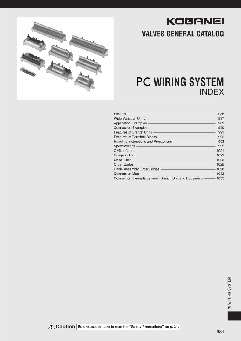
984 VALVES GENERAL CATALOG INDEX WIRING SYSTEM Before use, be sure to read the “Safety Precautions” on p. 31. Caution Features 985 Wide Variation Units 987 Application Examples 989 Connection Examples 990 Features of Branch Units 991 Features of Terminal Blocks 992 Handling Instructions and Precautions 993 Specifications 995 Okiflex Cable 1021 Crimping Tool 1022 Check Unit 1023 Order Codes 1025 Cable Assembly Order Codes 1028 Connection Map 1033 Connection Example between Branch Unit and Equipment 1035 PC WIRING SYSTEM
Transcript of WIRING SYSTEM - Koganei
984
VALVES GENERAL CATALOG
INDEXWIRING SYSTEM
Before use, be sure to read the “Safety Precautions” on p. 31.Caution
Features 985Wide Variation Units 987Application Examples 989Connection Examples 990Features of Branch Units 991Features of Terminal Blocks 992Handling Instructions and Precautions 993Specifications 995Okiflex Cable 1021Crimping Tool 1022Check Unit 1023Order Codes 1025Cable Assembly Order Codes 1028Connection Map 1033Connection Example between Branch Unit and Equipment 1035
PC W
IRIN
G SY
STEM
985
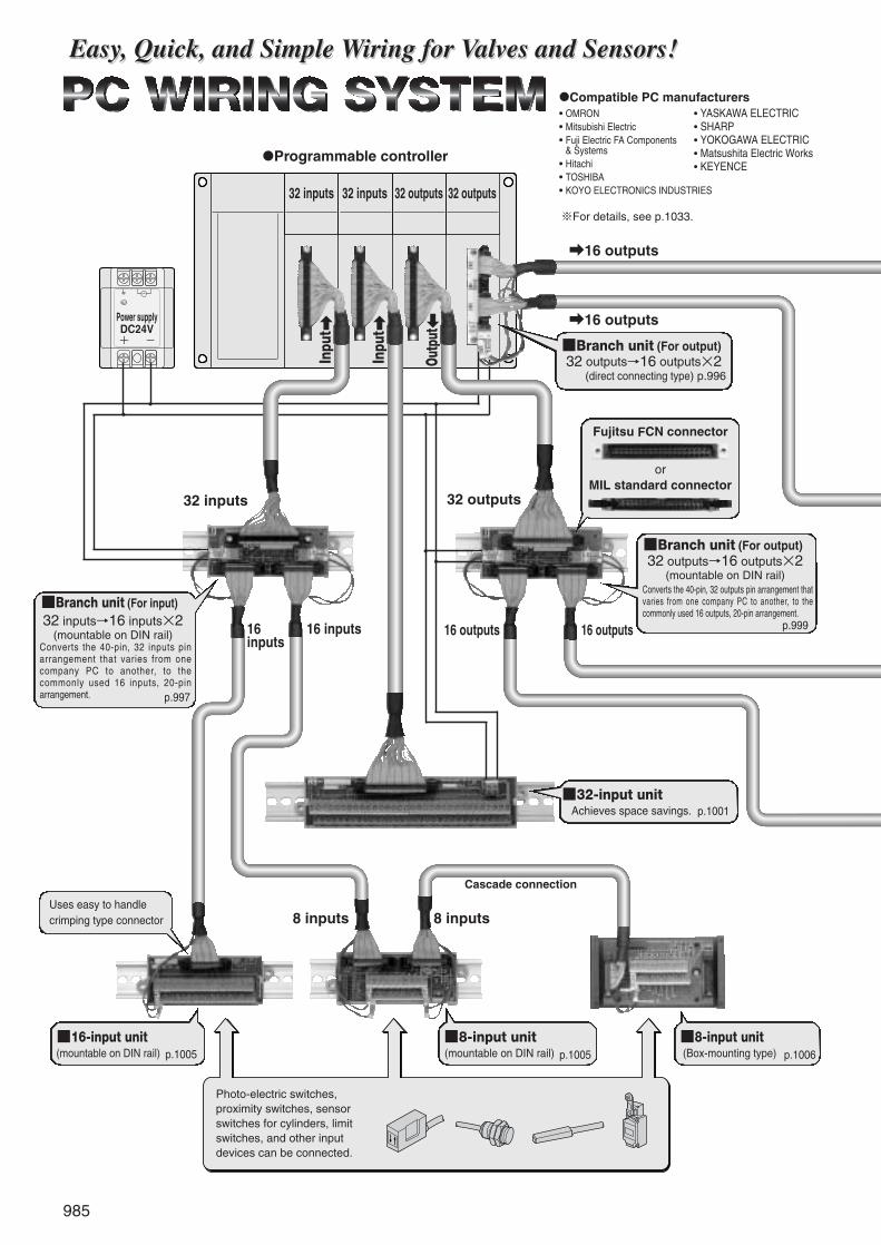
●Programmable controller
Photo-electric switches,proximity switches, sensorswitches for cylinders, limitswitches, and other inputdevices can be connected.
32 inputs 32 inputs 32 outputs 32 outputs
32 inputs
a16 outputs
a16 outputsPower supplyDC24V
■Branch unit (For output)32 outputs→16 outputs×2
(direct connecting type) p.996
Uses easy to handle crimping type connector
■8-input unit(Box-mounting type)
■8-input unit(mountable on DIN rail)
■16-input unit(mountable on DIN rail)
■32-input unitAchieves space savings.
■Branch unit (For output)32 outputs→16 outputs×2
(mountable on DIN rail)Converts the 40-pin, 32 outputs pin arrangement thatvaries from one company PC to another, to thecommonly used 16 outputs, 20-pin arrangement.
■Branch unit (For input)32 inputs→16 inputs×2
(mountable on DIN rail)Converts the 40-pin, 32 inputs pinarrangement that varies from onecompany PC to another, to thecommonly used 16 inputs, 20-pinarrangement.
Fujitsu FCN connector
orMIL standard connector
Easy, Quick, and Simple Wiring for Valves and Sensors!Easy, Quick, and Simple Wiring for Valves and Sensors!
●Compatible PC manufacturers• OMRON• Mitsubishi Electric• Fuji Electric FA Components• & Systems• Hitachi• TOSHIBA• KOYO ELECTRONICS INDUSTRIES
※For details, see p.1033.
• YASKAWA ELECTRIC• SHARP• YOKOGAWA ELECTRIC• Matsushita Electric Works• KEYENCE
Inpu
t a
Inpu
t a
Outp
utb
+ -
p.997
16 inputs16 inputs
p.1005
8 inputs 8 inputs
Cascade connection
p.1005 p.1006
p.1001
p.99916 outputs16 outputs
32 outputs

986
PC W
IRIN
G SY
STEM
Solenoid valves, relays, lamps, and otheroutput equipment can be connected.※8 and 32-output units are also
available.(The branch unit is not used when using the 32-output unit.)
●Unlike with serial transmission, there is no need to worryabout transmission delay time.●Visually and intuitively easy to understand, for simple
maintenance during setup, debugging and breakdowns.●No need for expensive systems; cuts initial costs as well.
●Special cable with power line is a remarkable flat cable thatincorporates a flat cable and the power line within a singleinsulation, eliminating the need for separate wiring of power line.●Cutting the special cable at any point and one operation crimping
connection help to achieve wiring savings equivalent to serialtransmission systems.●One operation crimping connector helps to standardize wiring
work, to prevent incorrect wiring, and to vastly improve opera-tions efficiency.
●The branch unit branches off the 32-I/O of the various PCmanufacturers into the 16-I/O common pin arrangement.●Converts to common pin arrangement to ensure
connection with the Koganei manifold type solenoidvalves, relay terminals, etc. of other companies, withoutundue concern for pin arrangement.●Can supply power to PC I/O units.●Branch units compatible with the I/O connectors of all PC
manufacturers are available.
■Compatible manifold type solenoid valve
Solenoid valves F seriesWith wiring specification -F201 (Positive common specification)
FM-SOLID MANIFOLD X80M, X88M seriesWith wiring module FMCR-F201, FMC-F201(Positive common specification)※Maximum control solenoids: 16
For details, see p.993.
Solenoid valves F Series (F10)
■16-output unit(mountable on DIN rail)
Parallel Type for Simplicity
Increased Wiring Savings
Branch Unit Offers Commonality
Solenoid valves F series (F15)
■Okiflex cableSpecial cable includes a flat cable and powerline in a single insulation.20 leads and 40 leads are available.
■Connector type 8-outputunit (main unit)
Cascade connection
8 outputs 8 outputs
p.1015
p.1021
■16-output common reduction unit
Unit reduces common terminalsto achieve superior space-savingbenefits.
※32-output unit is also available. p.1019
p.1007
Solenoid valves GF series (GF10)※Pre-wired common
987
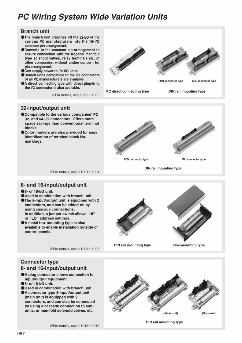
Branch unit●The branch unit branches off the 32-I/O of the
various PC manufacturers into the 16-I/Ocommon pin arrangement.
●Converts to the common pin arrangement toensure connection with the Koganei manifoldtype solenoid valves, relay terminals etc. ofother companies, without undue concern forpin arrangement.
●Can supply power to PC I/O units.●Branch units compatible to the I/O connectors
of all PC manufacturers are available.●A direct connecting type with direct plug-in to
the I/O connector is also available.
PC Wiring System Wide Variation Units
※For details, see p.995~1000.
32-input/output unit●Compatible to the various companies’ PC
32- and 64-I/O connectors. Offers morespace savings than conventional terminalblocks.
●Color markers are also provided for easyidentification of terminal block No.markings.
※For details, see p.1001~1004.
8- and 16-input/output unit●8- or 16-I/O unit.●Used in combination with branch unit.●The 8-input/output unit is equipped with 2
connectors, and can be added-on byusing cascade connections. In addition, a jumper switch allows “HI”or “LO” address settings.
●A metal box mounting type is alsoavailable to enable installation outside ofcontrol panels.
※For details, see p.1005~1008.
PC direct connecting type DIN rail mounting type
FCN connector type MIL connector type
DIN rail mounting type
DIN rail mounting type Box-mounting type
FCN connector type MIL connector type
Connector type8- and 16-input/output unit●A plug connector allows connection to
input/output equipment.●8- or 16-I/O unit.●Used in combination with branch unit.●A connector type 8-input/output unit
(main unit) is equipped with 2connectors, and can also be connectedby using a cascade connection to sub-units, or manifold solenoid valves, etc.
※For details, see p.1013~1016.
(Main unit)
DIN rail mounting type
(Sub-unit)

988
PC W
IRIN
G SY
STEM
8 LO-only input/output unit8 HI-only input/output unit●8-I/O unit.●Unit fixed at LO/HI eliminates need for
installing the jumper (short-circuit socket).●Used in combination with branch unit.●The unit is equipped with 2 connectors,
and can be added-on by using cascadeconnections.
●A metal box mounting type is alsoavailable to enable installation outside ofcontrol panels.
※For details, see p.994, 1009~1012.
Cable assembly (Made to order)
●Various cable assemblies with crimpedconnectors onto Okiflex cables are alsoavailable.
●Cable lengths offered from 0.5m [1.65ft.]to 20m [65.6ft.], by the 0.5m [1.65ft.] pitch.
※For details, see p.1028~1032.
16- and 32-output commonreduction unit●Unit reduces common terminal blocks for
excellent space-saving benefits. Includes a16-output type and a 32-output typecompatible with all companies’ PCs.
●32-output unit is compatible with allcompanies’ PC 32- and 64-outputconnectors.Color markers are also provided for easyidentification of terminal block No.markings.
●Use the 16-output unit in combination witha branch unit.
※For details, see p.1017~1019.
Associated products●Various kinds of crimping connectors●Okiflex cable
Remarkable cable incorporates a flatcable with power line within a singleinsulation for easy crimping onto aconnector.
●Crimping toolCrimping tools are compatible with allcrimping connectors used in PC wiringsystems.
●Check unitAllows easy function checking of variousunits, manifold type solenoid valves, andsensors.
FCN connector type MIL connector type
Okiflex cable
Check unit
Various connectors
Crimping tool
DIN rail mounting type
DIN rail mounting type
Box-mounting type
(16-output unit) (32-output unit)
※For details, see p.1021~1026.
989
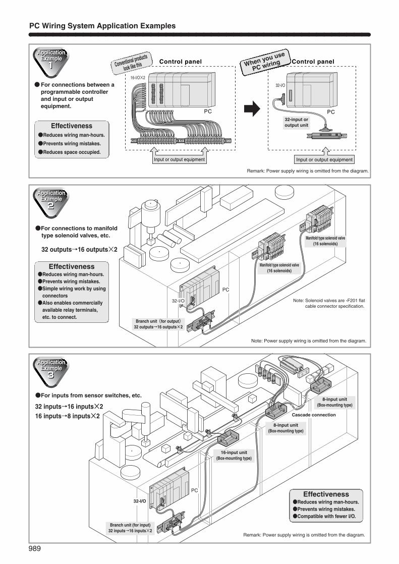
●For inputs from sensor switches, etc.
32 inputs→16 inputs×216 inputs→8 inputs×2
PC Wiring System Application Examples
PC PC
Control panel Control panel
Input or output equipment Input or output equipment
ae
●For connections to manifold type solenoid valves, etc.
32 outputs→16 outputs×2
PC
PC
Effectiveness●Reduces wiring man-hours.
●Prevents wiring mistakes.
●Reduces space occupied.
Remark: Power supply wiring is omitted from the diagram.
●For connections between aprogrammable controllerand input or outputequipment.
Conventional products
look like this When you use
PC wiring
16-I/O×2
32-I/O
32-input oroutput unit
Effectiveness●Reduces wiring man-hours.●Prevents wiring mistakes.●Simple wiring work by using
connectors●Also enables commercially
available relay terminals,etc. to connect.
Branch unit(for output)32 outputs→16 outputs×2
Manifold type solenoid valve(16 solenoids)
32-I/O
Manifold type solenoid valve(16 solenoids)
Note: Power supply wiring is omitted from the diagram.
Note: Solenoid valves are -F201 flatcable connector specification.
Branch unit (for input)32 inputs→16 inputs×2
16-input unit(Box-mounting type)
8-input unit(Box-mounting type)
Cascade connection
8-input unit(Box-mounting type)
32-I/OEffectiveness
●Reduces wiring man-hours.●Prevents wiring mistakes.●Compatible with fewer I/O.
Remark: Power supply wiring is omitted from the diagram.

990
PC W
IRIN
G SY
STEM
PC Wiring System Connection Examples
PCDC24V
Power supply
32-input unit
Branch unit(for output)
Branch unit(for input)
Wiring connection example
Okiflex cable
Heat-shrink tube
Flat cable
Crimping connector
Power line
Crimp type terminalCrimp type sleeve
Red colored wire
Note 3Triangle mark
32-output unit
8-input unit Relay terminal
16-input unit
16 manifold type solenoid valves
8 manifold type solenoid valves
8-output unit
Note 1 Note 1
Note 1Note 2
Note 1Note 2
Notes: 1. The rated current for each unit is a maximum of 2.0A (a maximum of 1.0A for the 8-input/output unit). When the transit current in each unitexceeds 2.0A (a maximum of 1.0A for the 8-input/output unit), use the same power supply terminal to connect the 2 power lines, and do not letcurrent flow through the unit.
2. When connecting the 8-input/output unit to manifold solenoid valves and relay terminals, as shown in the diagram above, set the unit jumper tothe “HI” side.
3. For the crimping of each type of a connector, see the separately issued User’s Manual for PC wiring systems (Document No.HV002).

991
Features of Branch Units in PC Wiring System
■Benefit No.1Use of a branch unit allows branching of 32-I/O→16-I/O×2.Branch units convert the 32-I/O, 40-pin arrangement that varies from one company PC to another, to the commonly used 16-I/O,20-pin arrangement. Because this pin arrangement follows the Koganei manifold solenoid valve series (wiring specification is the -F201 type, with positive common specification), and the various common specifications for peripheral equipment of variouscompanies on p.1035, connections can be made without undue concern for connector pin arrangement, etc.
■Benefit No.2Use of a branch unit enables power supply to the PC side I/O units.
■Benefit No.3Use of a branch unit reduces voltage drops, and enables long distance wiring.
●Example of connection with large voltage drop
●Since the common current line with the largest flow passes an exceedingly long distance to return to the negative polarity of thepower supply, the voltage drop increases quite a large amount.
●Example of connection using a branch unit to reduce the voltage dropInstall a branch unit near the I/O unit, and use the branch unit’s power supply terminal.
●Since the common current line with the largest flow can be routed an exceedingly short distance to return to the negative polarityof the power supply, the voltage drop remains small, and longer distance wiring is possible. In addition, use of an Okiflex cableeliminates the need for separate wiring for the power line.
COM
+�
-�
Solenoid
DC24VPower supply
PC side I/O unit(Output) Flat cable
Power supply for internal circuit
General terminal block
Power line(Separate wiring)
・�・�・�・�・�COM
・�・�・�・�・�
・�・�・�・�・�・�-�+�
00�
01�
02
+�
-�
A B A B A B
RS-
CN1 1� 2� 3� 4� � C
・�・�・�・�・�
・�
+�-�
+�-�
PC side I/O unit32 outputs(Sink type)
8- and 16-output unit, or manifold type solenoid valve, etc.
DC24VPower supply
Branch unit (for output)Okiflex cable withintegral power line 40 leads
COM
+�
-�
+�-�
Okiflex cable withintegral power line
Power supply for internal circuit
Solenoid
DC24VPower supply
PC side I/O unit(Output)
16-output unit
Branch unit(For output)
※Circuit details,etc. have beenomitted.
※Circuit details,etc. have beenomitted.
※Circuit details,etc. have beenomitted.
Wiring cannot extend for a long distance!
Wiring can go longdistance!

992
PC W
IRIN
G SY
STEM
■Easy-to-Use Common Terminal
The input or output unit provides a large number ofpositive (+) and negative (-) common terminals.Use of an input unit also eases connections to the 3-lead wire type sensor switch, etc.
No need to provide a separate common terminal block
For PC wiring systems, screw-pushed terminal blocks made by the major terminal block manufacturer Weidmuller are used.
1. A large contact surface and high contact pressure guarantee highly reliable and stable contact in ambient environments.2. The pitch between terminals on the terminal block is just 5.08mm [0.200in.], as compared to the generally used pitch 7.62~12mm [0.300~0.472in.], offering large space savings. This design saves a lot of space when using the same number ofterminals, or enables more terminals to be used in the same space, and reduces wiring work for common.
3. Since even stranded wire ensures high reliability without the use of crimp type terminals, the crimping process has notbeen required, reducing wiring man-hour to less than one-third than before. It also accepts bar terminals, crimp typesleeves, and other conventional wiring parts.
4. Because the electric contacts are not exposed, it makes use without covers (which are all too often lost duringmaintenance, anyway). In addition, the construction is designed to avoid terminal screw dropping losses.
5. When tightening the terminal screw, the effects of a double nut maintain high vibration resistance, and prevent loosenessin the screw. In addition, a special heat treatment of the clamp improves mechanical stress.
6. Meets the UL, CSA, VDE and other standards (terminal block alone).
■Double Nut EffectTightening the terminal screw generates a reaction force that causes the bent portion near the top of the clamp to restore, thusachieving the double nut effect.
Before tightening After tightening
Power line(+):Brown
Power line(-):Blue
Bro
wn
Blu
e
Bro
wn
Bla
ck
Blu
e Limit switch
3-lead wire type sensor switch for cylinder
�
2-lead wire type proximity switch
● Photo shows a 16-input unit.
Use of new Phillips type head screws has further eased work.
Conventional product New type
■Terminal Block Screw
Caution: For the terminal screw tightening torques,see each specifications.
Features of Terminal Blocks Used in PC Wiring System

993
191817
20
1615141312111
987
10
65432
357
1
9111315171920
468
2
1012141618
+� 15(F)� 14(E)�
-�
13(D)� 12(C)� 11(B)� 10(A)�090800
+�0706
-�
0504030201
191817
20
1615141312111
987
10
65432
357
1
9111315171920
468
2
1012141618
+�
15(F)� 14(E)�
-�
13(D)� 12(C)� 11(B)� 10(A)�090800
+�
0706
-�
0504030201
+� +�
-� -�
15(F) 0714(E) 0613(D) 0512(C) 0411(B) 0310(A) 0209 0108 00
-� -�
+� +�
15(F) 0714(E) 0613(D) 0512(C) 0411(B) 0310(A) 0209 0108 00
No. 1 wire(Red mark)
No. 1 wire(Red mark)
Handling Instructions and Precautions
11 12 13 14 15 16 17 18 19 20
1 2 3 4 5 6 7 8 9 10
Triangle mark
1
18
10, 20
9, 19
8�11
1
18
10, 20
9, 19
8�11
Powersupply terminal
Solenoid
LEDfor
powersupply
LEDfor
powersupply
Powersupply terminal
Reverse connection protection diode
Reverse connection protection diode
Solenoid
Solenoid
Built-in to the base
Connections to Koganei Manifold Type Solenoid Valves
Branch units in the PC wiring system convert the 32-I/O, 40-pin arrangement that varies from one company PC to another, to the commonly used 16-I/O, 20-pin arrangement.This pin arrangement accommodates the PC wiring system’s 8- and 16-input/output units (excluding input/output units for the Mitsubishi ElectricFX2 and FX2C series), the Koganei manifold type solenoid valve series, and the various common specifications for peripheral equipment of variouscompanies on p.1035. Take particular care about connecting to any other peripheral equipment.
Cautions: 1. The “positive polarity” and “negative polarity” positions differ between the input system and output system. Since an improper connection between theinput system and output system equipment can cause a “short circuit”, take particular care for this.
Cautions: 2. Although the pin arrangement varies between the Koganei manifold and PC wiring system, the physical arrangement characteristics are the same. For connection to other companies’ peripheral equipment, use the triangle mark and nose position as the reference.
About the Flat Cable Connector Pin Arrangement
1. Always use a voltage of DC24V or less.2. After wiring is complete, check for incorrect connections before turning on the power.3. Never disconnect any connectors when the power is on. Also, never apply unnecessary stress on the connectors.4. Use a dedicated crimping tool when performing cable crimping work. In addition, always check the crimped conditions before operation.5.The Okiflex cable is a cable for fixed wiring. Never apply any repetitive bending or tensile force to it.
Precautions for Use
●For input systems
●For output systems
Indication example 1 Indication example 2
Indication example 1 Indication example 2
Actual arrangement
20 leads flat cable
20 leads flat cable
Triangle mark
Nose
Triangle mark
Nose
Actual arrangement
Compatible manifold
Solenoid valves Fseries
FM-SOLID MANIFOLDX80M series
FM-SOLID MANIFOLDX88M series
Wiring specification
Positive common specificationWiring specification -F201
Positive common specificationWiring module FMCR-F201
Positive common specificationWiring module FMC-F201
1. Pin arrangement of connector
●Solenoid valves F seriesFlat cable connector -F201
●FM-SOLID MANIFOLD X80M, X88M seriesFlat cable connector FMCR-F201, FMC-F201
1~8 : Control pins11~18 : Control pins9,19 : (-) pins (short-circuited within module)10, 20 : (+) pins (short-circuited within module)
Notes:1. The connector pin numbers are assignedfor the sake of convenience. Use the ▼mark as the reference.
2. While the pin location identification methoddiffers from the PC wiring system, thearrangement is equivalent in real usage.
2. Detailed diagram of wiring systems
●Positive commonX80M series
Solenoid valves F series/X88M series
When using a branch unit to connect theKoganei manifold type solenoid valves, seethe table below for compatible manifolds:

994
PC W
IRIN
G SY
STEM
CN1 CN2Note2
CN1CN1 CN2Note2
Precautions for Use of the 8- and 16-Input/Output Units
(DIN rail mounting type, Box-mounting type)
1. About the nameplateEvery PC manufacturer has its own way of assigning I/O addresses.A general use (can be used with any manufacturer) nameplate kit isavailable. Cut it as required, and then fit it into the terminal nameplateportion.Fit the nameplate so that the address runs from the left of the � markon the circuit board to right to increase.
2. About cascade connections(8-input/output unit)
For cascade connections, use thejumper (short-circuit socket) to assignthe addresses to either the “LO” side 0~7 or the “HI” side 8~F(15).In setting the “LO” side address, the“LO” side is shorted. It has been set tothe “LO” side when shipped from thefactory.
Cautions: When the 8-input/output unit is used for 2 cascadeconnections, do not set each jumper setting as LO and LO,or HI and HI, for not sharing the same address.
Cautions: (In the case of input, it becomes OR circuits with 2sensors, and operating problems will occur.)
1. About cascade connectionsThe connector type 8-input/output unit can be used in cascadeconnections between main units and sub-units, or in cascadeconnections between main units and other equipment.
Caution: As the connector type input/output unit does not include ajumper (short-circuit socket), caution should be exercisedwhen selecting a product.
L H L H
76
10
FE
98
FE
98
76
10
“LO” Setting “HI” Setting
Precautions for Use of the Connector Type Input/Output Unit
2. About the 3-pin connectorFor the housings and terminals for the mounted wafer (3 pins), usethe items shown below:
Koganei model: FMA-BM03A(10 housings and 30 terminals make 1 set.)
●Applicable housingMade by Molex JapanModel No. 51103-0300
●Applicable terminalMade by Molex JapanModel No. 50351-8100
Applicable wireLead wire size : AWG No.28...22Insulation outer diameter : φ1.15~φ1.8mm [φ0.0453~φ0.071in.]Exposed wire length : 2.3~2.8mm [0.091~0.110in.]
Applicable crimping toolMade by Molex JapanModel No. 57295-5000
ExtractorModel No. 57309-6000
3. About the 8 LO/HI-only input/output unitUnit for fixed LO/HI that does not require jumper (short-circuit socket)settings.
●LO-only unitFMA-TJ1108, FMA-TJ2108FMA-TJ1008, FMA-TJ2008Address allocation is fixed to the “LO” side (0~7).
●HI-only unitFMA-TK1108, FMA-TK2108FMA-TK1008, FMA-TK2008Address allocation is fixed to the “HI” side (8~F(15)).
8-input/output unitFMA-TM1108 (-MB)FMA-TM1008 (-MB)
8-input/output unitFMA-TM1108 (-MB)FMA-TM1008 (-MB)
Jumper settingAddress
LO0~7
Jumper settingAddress
HI8~F (15)
q First unit: 8-input/output unit Second unit: 8-input/output unit
When the first 8-input/output unit is set to the “LO” side address, set thesecond 8-input/output unit to the “HI” side.
●Connection example for cascade connectionsNote 1
w First unit: 8-output unit Second unit: Manifold
For the manifold, use the “LO” side address. Therefore, use the “HI”setting for the 8-output unit.Note: When the manifold address is set on the “HI” side, the address is 8
~F(15), or when the manifold is connected to the first unit, themanifold should be a special specification. Consult us.
8-output unitFMA-TM1008 (-MB)
Manifold mounted F201
Jumper settingAddress
HI8~F (15)
Jumper settingAddress
Without setting0~7
Notes:1. For cascade connections, see the circuit diagram.2. CN1 and CN2 have identical pin arrangements. (For details,
see the circuit diagram.)
q First unit: Connector type 8-input/output unit (main unit)Second unit: Connector type 8-input/output unit (sub-unit)
Connector type 8-input/output unit (main unit)FMA-TC1108FMA-TC1008
Connector type 8-input/output unit (sub-unit)FMA-TD1108FMA-TD1008
Address 0~7 Address 8~F (15)
●Connection example for cascade connectionsNote 3
CN-PC1 CN-PC1CN-PC2Note 4
w First unit: Connector type 8-output unit (main unit)Second unit: Manifold
Connector type 8-output unit (main unit)FMA-TC1008
Manifold mounted F201
Address 8~F (15)Address 0~7
CN-PC1 CN-PC2Note 4
Notes: 3. For cascade connections, see the circuit diagram.4. The CN-PC1 and CN-PC2 do not have identical pin
arrangements.(For details, see the circuit diagram.)

995
Dimensions (mm) Dimensions (mm)
●Branch unit (Input)[For OMRON]●FMA-TF3120-OR
●Branch unit (Input)[For Mitsubishi Electric]●FMA-TF3120-MBA, FMA-TF3120-MBB
Circuit diagram Circuit diagram
●FMA-TF3120-MBA ●FMA-TF3120-MBB
INCN1
CN2
(5.2)
16.5
23.1
27.4
18.2
70.1
INCN1
CN2
(5.2)
16.5
23.1
27.4
18.2
70.1
INCN2
CN1
(5.2)
16.5
23.1
27.4
18.2
70.1
※Differs from Mitsubishi Electric’s pin arrangement identification method.
Branch Unit, Programmable Controller Direct Connecting TypeFor OMRON, Input/For Mitsubishi Electric, Input
B1 B2 B3 B4 B5 B6 B7 B8 B9 B10 B11 B12 B13 B15B14 B16 B18B17 B19 B20
A1 A2 A3 A4 A5 A6 A7 A8 A9 A10 A11 A12 A13 A15A14 A16 A18A17 A19 A20
10 11 12 13 14 15 16 17
18 19 1A 1B 1C 1D 1E 1F
28 29 2A 2B 2C 2D 2E 2F
20 21 22 23 24 25 26 27
1C 1B 1A 1F 19 1E 18 1D
14 13 12 17 11 16 1015
111
133
155
177
199
2010
188
166
144
122
2C 2B 2A 2F 29 2E 28 2D
24 23 22 27 21 26 20 25
111
133
155
177
199
2010
188
166
144
122
+
CN0FCN-364J040 [Fujitsu]
LPA2/2 [Nihon Weidmuller]
JM1P-0202 [IDEC Izumi]CN2
JM1P-0202 [IDEC Izumi]CN1
10 11 12 13 14 15 16 17
18 19 1A 1B 1C 1D 1E 1F
28 29 2A 2B 2C 2D 2E 2F
20 21 22 23 24 25 26 27
1C 1B 1A 1F 19 1E 18 1D
14 13 12 17 11 16 1015
111
133
155
177
199
2010
188
166
144
122
2C 2B 2A 2F 29 2E 28 2D
24 23 22 27 21 26 20 25
111
133
155
177
199
2010
188
166
144
122
A20 A19 A18 A17 A16 A15 A14 A13 A12 A11 A10 A9 A8 A6A7 A5 A3A4 A2 A1
B20 B19 B18 B17 B16 B15 B14 B13 B12 B11 B10 B9 B8 B6B7 B5 B3B4 B2 B1+
CN0FCN-364J040 [Fujitsu]
LPA2/2 [Nihon Weidmuller]
※
JM1P-0202 [IDEC Izumi]CN2
JM1P-0202 [IDEC Izumi]CN1
Specifications
Parts
Model
Compatible
PC
Rated voltage
Rated current
Dielectric strength
Tightening torque for the terminal screw
AWG
Connecting wire size (Terminal block)
Solid wire〈H05(07)V-U〉
Stranded wire〈H05(07)V-K〉
Exposed wire length (Terminal block)
Installed terminal block (For power supply)
Installed connector (40 pins)
Installed connector (20 pins, half pitch)
Mating connector (20 pins, half pitch)
Operating temperature range
Mass
DC24V
AC250V r.m.s.
0.4~0.6N・m {0.04~0.06kgf・m} [3.5~5.3in・lbf]
No.26...14
0.13~2.5mm2 [0.00020~0.00388in.2]
0.5~2.5mm2 [0.00078~0.00388in.2]
0.5~2.5mm2 [0.00078~0.00388in.2]
7mm [0.276in.]
LPA2/2〈Made by Nihon Weidmuller〉
FCN-364J040〈Made by Fujitsu〉
JM1P-0202〈Made by IDEC Izumi〉
JM1S-0203〈Made by IDEC Izumi〉
-25~55°C [-13~131°F]
25g [0.88oz.]
Branch unit (Input)
FMA-TF3120-OR
OMRON
C200H-ID216
C500-ID219, C200H-ID217
0.3A/input, 2A/unit
Branch unit (Input)
FMA-TF3120-MBA, FMA-TF3120-MBB
Mitsubishi Electric
A1SX41
AX42, A1SX42Note
0.3A/input, 2A/unit
Note : When using with the Mitsubishi Electric A1SX42, use it in combination with one FMA-TF3120-MBA and one FMA-TF3120-MBB.Remark : Rating is for the unit alone. When other connection units exist, their ratings must also be taken into consideration.
PC manufacturer
Compatible with 32-input model
Compatible with 64-input model (32-input×2)

996
PC W
IRIN
G SY
STEM
●Branch unit (Output)[For OMRON]●FMA-TF3020-OR
●Branch unit (Output)[For Mitsubishi Electric]●FMA-TF3020-MBA, FMA-TF3020-MBB
●FMA-TF3020-MBA ●FMA-TF3020-MBB
B1 B2 B3 B4 B5 B6 B7 B8 B9 B10 B11 B12 B13 B15B14 B16 B18B17 B19 B20
A1 A2 A3 A4 A5 A6 A7 A8 A9 A10 A11 A12 A13 A15A14 A16 A18A17 A19 A20
10 11 12 13 14 15 16 17
18 19 1A 1B 1C 1D 1E 1F
28 29 2A 2B 2C 2D 2E 2F
20 21 22 23 24 25 26 27
1C 1B 1A 1F 19 1E 18 1D
14 13 12 17 11 16 1015
111
133
155
177
199
2010
188
166
144
122
2C 2B 2A 2F 29 2E 28 2D
24 23 22 27 21 26 20 25
111
133
155
177
199
2010
188
166
144
122
+
CN0FCN-364J040 [Fujitsu]
LPA2/2 [Nihon Weidmuller]
JM1P-0202 [IDEC Izumi]CN2
JM1P-0202 [IDEC Izumi]CN1
OUT
CN1
CN2
(5.2)
16.5
23.1
27.4
18.2
70.1
OUT
CN1
CN2
(5.2)
16.5
23.1
27.4
18.2
70.1
OUT
CN2
CN1
(5.2)
16.5
23.1
27.4
18.2
70.1
※Differs from Mitsubishi Electric’s pin arrangement identification method.
10 11 12 13 14 15 16 17
18 19 1A 1B 1C 1D 1E 1F
28 29 2A 2B 2C 2D 2E 2F
20 21 22 23 24 25 26 27
1C 1B 1A 1F 19 1E 18 1D
14 13 12 17 11 16 1015
111
133
155
177
199
2010
188
166
144
122
2C 2B 2A 2F 29 2E 28 2D
24 23 22 27 21 26 20 25
111
133
155
177
199
2010
188
166
144
122
A20 A19 A18 A17 A16 A15 A14 A13 A12 A11 A10 A9 A8 A6A7 A5 A3A4 A2 A1
B20 B19 B18 B17 B16 B15 B14 B13 B12 B11 B10 B9 B8 B6B7 B5 B3B4 B2 B1+
CN0FCN-364J040 [Fujitsu]
LPA2/2 [Nihon Weidmuller]
※
JM1P-0202 [IDEC Izumi]CN2
JM1P-0202 [IDEC Izumi]CN1
Branch Unit, Programmable Controller Direct Connecting TypeFor OMRON, Output/For Mitsubishi Electric, Output
Dimensions (mm) Dimensions (mm)
Circuit diagram Circuit diagram
Specifications
Parts
Model
Compatible
PC
Rated voltage
Rated current
Dielectric strength
Tightening torque for the terminal screw
AWG
Connecting wire size (Terminal block)
Solid wire〈H05(07)V-U〉
Stranded wire〈H05(07)V-K〉
Exposed wire length (Terminal block)
Installed terminal block (For power supply)
Installed connector (40 pins)
Installed connector (20 pins, half pitch)
Mating connector (20 pins, half pitch)
Operating temperature range
Mass
DC24V
AC250V r.m.s.
0.4~0.6N・m {0.04~0.06kgf・m} [3.5~5.3in・lbf]
No.26...14
0.13~2.5mm2 [0.00020~0.00388in.2]
0.5~2.5mm2 [0.00078~0.00388in.2]
0.5~2.5mm2 [0.00078~0.00388in.2]
7mm [0.276in.]
LPA2/2〈Made by Nihon Weidmuller〉
FCN-364J040〈Made by Fujitsu〉
JM1P-0202〈Made by IDEC Izumi〉
JM1S-0203〈Made by IDEC Izumi〉
-25~55°C [-13~131°F]
25g [0.88oz.]
Branch unit (Output)
FMA-TF3020-OR
OMRON
C200H-OD218
C500-OD213, C200H-OD219
0.3A/output, 2A/unit
Branch unit (Output)
FMA-TF3020-MBA, FMA-TF3020-MBB
Mitsubishi Electric
A1SY41
AY42, A1SY42Note
0.3A/output, 2A/unit
Note : When using with the Mitsubishi Electric A1SY42, use it in combination with one FMA-TF3020-MBA and one FMA-TF3020-MBB.Remark : Rating is for the unit alone. When other connection units exist, their ratings must also be taken into consideration.
PC manufacturer
Compatible with 32-output model
Compatible with 64-output model (32-output×2)

997
49
28.3
50.5
103
4.5
16.7
4.1
5.1
10.5 10.5
55
CN2CN1
CN0
RS
(3.5)�45
49
28.3
50.5
103
4.5
16.7
4.1
5.1
10.5 10.5
55
OUTIN
CN2CN1
C1
C2 8�7�6�5�
4�3�2�1�
CN0
RS
(3.5)�
45
●Branch unit (Input)●FMA-TF4120-OR●FCN connector type
●Branch unit (Input)●FMA-TE4120-OR●MIL connector type
Branch Unit, DIN Rail Mounting TypeFor OMRON, Input
B1 B2 B3 B4 B5 B6 B7 B8 B9 B10 B11 B12 B13 B15B14 B16 B18B17 B19 B20
A1 A2 A3 A4 A5 A6 A7 A8 A9 A10 A11 A12 A13 A15A14 A16 A18A17 A19 A20
10 11 12 13 14 15 16 17
18 19 1A 1B 1C 1D 1E 1F
28 29 2A 2B 2C 2D 2E 2F
20 21 22 23 24 25 26 27
1F 1E 1D 1C 1B 1A 19 18
17 16 15 14 13 12 11 10
2
1
4
3
6
5
8
7
10
9
12
11
14
13
16
15
18
17
20
19
2F 2E 2D 2C 2B 2A 29 28
27 26 25 24 23 22 21 20
2
1
4
3
6
5
8
7
10
9
12
11
14
13
16
15
18
17
20
19
+ +
CN0FCN-364P040 [Fujitsu]
LPA1/2 [Nihon Weidmuller]
LPA1/2 [Nihon Weidmuller]
FL20A2MS [Oki Electric Cable]CN1
FL20A2MS [Oki Electric Cable]CN2
2 4 6 8 10 12 14 16 18 20 22 24 26 3028 32 3634 38 40
1 3 5 7 9 11 13 15 17 19 21 23 25 2927 31 3533 37 39
10 11 12 13 14 15 16 17
18 19 1A 1B 1C 1D 1E 1F
28 29 2A 2B 2C 2D 2E 2F
20 21 22 23 24 25 26 27
1F 1E 1D 1C 1B 1A 19 18
17 16 15 14 13 12 11 10
2
1
4
3
6
5
8
7
10
9
12
11
14
13
16
15
18
17
20
19
2F 2E 2D 2C 2B 2A 29 28
27 26 25 24 23 22 21 20
2
1
4
3
6
5
8
7
10
9
12
11
14
13
16
15
18
17
20
19
+ +
CN0FL40A2MS [Oki Electric Cable]
LPA1/2 [Nihon Weidmuller]
LPA1/2 [Nihon Weidmuller]
FL20A2MS [Oki Electric Cable]CN1
FL20A2MS [Oki Electric Cable]CN2
Dimensions (mm) Dimensions (mm)
Circuit diagram Circuit diagram
For the circuit diagrams and specifications of branch units forother manufacturers, consult us.
Specifications
Parts
Model
Compatible
PC
Rated voltage
Rated current
Dielectric strength
Tightening torque for the terminal screw
AWG
Connecting wire size (Terminal block)
Solid wire〈H05(07)V-U〉
Stranded wire〈H05(07)V-K〉
Exposed wire length (Terminal block)
Installed terminal block (For power supply)
Installed connector (40 pins)
Installed MIL connector (20 pins)
Mating connector (40 pins)
Mating MIL connector (20 pins)
Operating temperature range
Mass
OMRON
C200H-ID216, CQM1-ID213
C500-ID219, C200H-ID217
DC24V
0.3A/input, 2A/unit
AC500V r.m.s.
0.4~0.6N・m {0.04~0.06kgf・m} [3.5~5.3in・lbf]
No.26...14
0.13~2.5mm2 [0.00020~0.00388in.2]
0.5~2.5mm2 [0.00078~0.00388in.2]
0.5~2.5mm2 [0.00078~0.00388in.2]
7mm [0.276in.]
LPA1/2〈Made by Nihon Weidmuller〉
FL20A2MS〈Made by Oki Electric Cable〉
FL20A2FO〈Made by Oki Electric Cable〉or equivalent
-25~80°C [-13~176°F]
Branch unit (Input) FCN connector type
FMA-TF4120-OR
FCN-367J040〈Made by Fujitsu〉
85g [3.00oz.]
FL40A2FO〈Made by Oki Electric Cable〉or equivalent Note
80g [2.82oz.]
FCN-364P040〈Made by Fujitsu〉 FL40A2MS〈Made by Oki Electric Cable〉Note
Branch unit (Input) MIL connector type
FMA-TE4120-OR
Note : For the compatible model of -KY: KEYENCE, the installed connector (34 pins) is Oki Electric Cable’s FL34A2MS. The mating connector should beFL34A2FO (made by Oki Electric Cable) or equivalent.
Remark : Rating is for the unit alone. When other connection units exist, their ratings must also be taken into consideration.
PC manufacturer
Compatible with 32-input model
Compatible with 64-input model (32-input×2)

998
PC W
IRIN
G SY
STEM
Branch Unit, DIN Rail Mounting TypeFor Mitsubishi Electric, Input
49
28.3
50.5
103
4.5
16.7
4.1
5.1
10.5 10.5
55
OUTIN
CN2CN1
C1
C2 8�7�6�5�
4�3�2�1�
RS
(3.5)�
45
CN0
49
28.3
50.5
103
4.5
16.7
4.1
5.1
10.5 10.5
55
CN2CN1
CN0
RS
(3.5)�45
●Branch unit (Input)●FMA-TF4120-MB●FCN connector type
●Branch unit (Input)●FMA-TE4120-MB●MIL connector type
39 37 35 33 31 29 27 25 23 21 19 17 15 1113 9 57 3 1
10 11 12 13 14 15 16 17
18 19 1A 1B 1C 1D 1E 1F
28 29 2A 2B 2C 2D 2E 2F
20 21 22 23 24 25 26 27
40 38 36 34 32 30 28 26 24 22 20 18 16 1214 10 68 4 2
1F 1E 1D 1C 1B 1A 19 18
17 16 15 14 13 12 11 10
2
1
4
3
6
5
8
7
10
9
12
11
14
13
16
15
18
17
20
19
2F 2E 2D 2C 2B 2A 29 28
27 26 25 24 23 22 21 20
2
1
4
3
6
5
8
7
10
9
12
11
14
13
16
15
18
17
20
19
+ +
CN0FL40A2MS [Oki Electric Cable]
LPA1/2 [Nihon Weidmuller]
LPA1/2 [Nihon Weidmuller]
FL20A2MS [Oki Electric Cable]CN1
FL20A2MS [Oki Electric Cable]CN2
A20 A19 A18 A17 A16 A15 A14 A13 A12 A11 A10 A9 A8 A6A7 A5 A3A4 A2 A1
10 11 12 13 14 15 16 17
18 19 1A 1B 1C 1D 1E 1F
28 29 2A 2B 2C 2D 2E 2F
20 21 22 23 24 25 26 27
B20 B19 B18 B17 B16 B15 B14 B13 B12 B11 B10 B9 B8 B6B7 B5 B3B4 B2 B1
1F 1E 1D 1C 1B 1A 19 18
17 16 15 14 13 12 11 10
2
1
4
3
6
5
8
7
10
9
12
11
14
13
16
15
18
17
20
19
2F 2E 2D 2C 2B 2A 29 28
27 26 25 24 23 22 21 20
2
1
4
3
6
5
8
7
10
9
12
11
14
13
16
15
18
17
20
19
+ +
CN0FCN-364P040 [Fujitsu]
LPA1/2 [Nihon Weidmuller]
LPA1/2 [Nihon Weidmuller]
FL20A2MS [Oki Electric Cable]CN1
FL20A2MS [Oki Electric Cable]CN2
※
※Differs from Mitsubishi Electric’s pin arrangement identification method.
For the circuit diagrams and specifications of branch units forother manufacturers, consult us.
Dimensions (mm) Dimensions (mm)
Circuit diagram Circuit diagram
Specifications
Parts
Model
Compatible
PC
Rated voltage
Rated current
Dielectric strength
Tightening torque for the terminal screw
AWG
Connecting wire size (Terminal block)
Solid wire〈H05(07)V-U〉
Stranded wire〈H05(07)V-K〉
Exposed wire length (Terminal block)
Installed terminal block (For power supply)
Installed connector (40 pins)
Installed MIL connector (20 pins)
Mating connector (40 pins)
Mating MIL connector (20 pins)
Operating temperature range
Mass
Mitsubishi Electric
A1SX41, AJ35TC1-32D
AX42, A1SX42
DC24V
0.3A/input, 2A/unit
AC500V r.m.s.
0.4~0.6N・m {0.04~0.06kgf・m} [3.5~5.3in・lbf]
No.26...14
0.13~2.5mm2 [0.00020~0.00388in.2]
0.5~2.5mm2 [0.00078~0.00388in.2]
0.5~2.5mm2 [0.00078~0.00388in.2]
7mm [0.276in.]
LPA1/2〈Made by Nihon Weidmuller〉
FL20A2MS〈Made by Oki Electric Cable〉
FL20A2FO〈Made by Oki Electric Cable〉or equivalent
-25~80°C [-13~176°F]
Branch unit (Input) FCN connector type
FMA-TF4120-MB
Branch unit (Input) MIL connector type
FMA-TE4120-MB
Note : For the compatible model of -KY: KEYENCE, the installed connector (34 pins) is Oki Electric Cable’s FL34A2MS. The mating connector should beFL34A2FO (made by Oki Electric Cable) or equivalent.
Remark: Rating is for the unit alone. When other connection units exist, their ratings must also be taken into consideration.
PC manufacturer
Compatible with 32-input model
Compatible with 64-input model (32-input×2)
FCN-367J040〈Made by Fujitsu〉
85g [3.00oz.]
FL40A2FO〈Made by Oki Electric Cable〉or equivalent Note
80g [2.82oz.]
FCN-364P040〈Made by Fujitsu〉 FL40A2MS〈Made by Oki Electric Cable〉Note
999
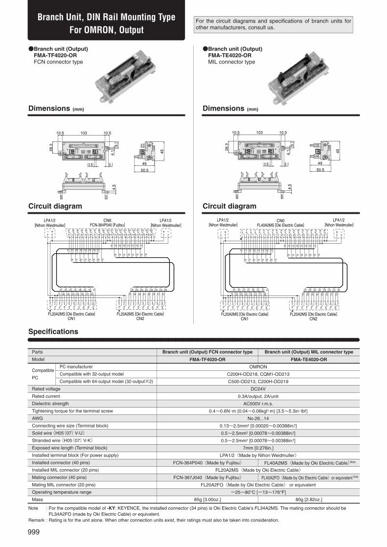
●Branch unit (Output)●FMA-TF4020-OR●FCN connector type
●Branch unit (Output)●FMA-TE4020-OR●MIL connector type
49
28.3
50.5
103
4.5
16.7
4.1
5.1
10.5 10.5
55
CN2CN1
CN0
RS
(3.5)�45
49
28.3
50.5
103
4.5
16.7
4.1
5.1
10.5 10.5
55
OUTIN
CN2CN1
C1
C2 8�7�6�5�
4�3�2�1�
CN0
RS
(3.5)�
45
B1 B2 B3 B4 B5 B6 B7 B8 B9 B10 B11 B12 B13 B15B14 B16 B18B17 B19 B20
A1 A2 A3 A4 A5 A6 A7 A8 A9 A10 A11 A12 A13 A15A14 A16 A18A17 A19 A20
10 11 12 13 14 15 16 17
18 19 1A 1B 1C 1D 1E 1F
28 29 2A 2B 2C 2D 2E 2F
20 21 22 23 24 25 26 27
1F 1E 1D 1C 1B 1A 19 18
17 16 15 14 13 12 11 10
2
1
4
3
6
5
8
7
10
9
12
11
14
13
16
15
18
17
20
19
2F 2E 2D 2C 2B 2A 29 28
27 26 25 24 23 22 21 20
2
1
4
3
6
5
8
7
10
9
12
11
14
13
16
15
18
17
20
19
++
CN0FCN-364P040 [Fujitsu]
LPA1/2 [Nihon Weidmuller]
LPA1/2 [Nihon Weidmuller]
FL20A2MS [Oki Electric Cable]CN1
FL20A2MS [Oki Electric Cable]CN2
2 4 6 8 10 12 14 16 18 20 22 24 26 3028 32 3634 38 40
1 3 5 7 9 11 13 15 17 19 21 23 25 2927 31 3533 37 39
10 11 12 13 14 15 16 17
18 19 1A 1B 1C 1D 1E 1F
28 29 2A 2B 2C 2D 2E 2F
20 21 22 23 24 25 26 27
1F 1E 1D 1C 1B 1A 19 18
17 16 15 14 13 12 11 10
2
1
4
3
6
5
8
7
10
9
12
11
14
13
16
15
18
17
20
19
2F 2E 2D 2C 2B 2A 29 28
27 26 25 24 23 22 21 20
2
1
4
3
6
5
8
7
10
9
12
11
14
13
16
15
18
17
20
19
++
CN0FL40A2MS [Oki Electric Cable]
LPA1/2 [Nihon Weidmuller]
LPA1/2 [Nihon Weidmuller]
FL20A2MS [Oki Electric Cable]CN1
FL20A2MS [Oki Electric Cable]CN2
Branch Unit, DIN Rail Mounting TypeFor OMRON, Output
For the circuit diagrams and specifications of branch units forother manufacturers, consult us.
Dimensions (mm) Dimensions (mm)
Circuit diagram Circuit diagram
Specifications
Parts
Model
Compatible
PC
Rated voltage
Rated current
Dielectric strength
Tightening torque for the terminal screw
AWG
Connecting wire size (Terminal block)
Solid wire〈H05(07)V-U〉
Stranded wire〈H05(07)V-K〉
Exposed wire length (Terminal block)
Installed terminal block (For power supply)
Installed connector (40 pins)
Installed MIL connector (20 pins)
Mating connector (40 pins)
Mating MIL connector (20 pins)
Operating temperature range
Mass
OMRON
C200H-OD218, CQM1-OD213
C500-OD213, C200H-OD219
DC24V
0.3A/output, 2A/unit
AC500V r.m.s.
0.4~0.6N・m {0.04~0.06kgf・m} [3.5~5.3in・lbf]
No.26...14
0.13~2.5mm2 [0.00020~0.00388in.2]
0.5~2.5mm2 [0.00078~0.00388in.2]
0.5~2.5mm2 [0.00078~0.00388in.2]
7mm [0.276in.]
LPA1/2〈Made by Nihon Weidmuller〉
FL20A2MS〈Made by Oki Electric Cable〉
FL20A2FO〈Made by Oki Electric Cable〉 or equivalent
-25~80°C [-13~176°F]
Branch unit (Output) FCN connector type
FMA-TF4020-OR
Branch unit (Output) MIL connector type
FMA-TE4020-OR
Note : For the compatible model of -KY: KEYENCE, the installed connector (34 pins) is Oki Electric Cable’s FL34A2MS. The mating connector should beFL34A2FO (made by Oki Electric Cable) or equivalent.
Remark : Rating is for the unit alone. When other connection units exist, their ratings must also be taken into consideration.
PC manufacturer
Compatible with 32-output model
Compatible with 64-output model (32-output×2)
FCN-367J040〈Made by Fujitsu〉
85g [3.00oz.]
FL40A2FO〈Made by Oki Electric Cable〉or equivalent Note
80g [2.82oz.]
FCN-364P040〈Made by Fujitsu〉 FL40A2MS〈Made by Oki Electric Cable〉Note

1000
PC W
IRIN
G SY
STEM
●Branch unit (Output)●FMA-TF4020-MB●FCN connector type
●Branch unit (Output)●FMA-TE4020-MB●MIL connector type
49
28.3
50.5
103
4.5
16.7
4.1
5.1
10.5 10.5
55
OUTIN
CN2CN1
C1
C2 8�7�6�5�
4�3�2�1�
RS
(3.5)�
45
CN0
49
28.3
50.5
103
4.5
16.7
4.1
5.1
10.5 10.5
55
CN2CN1
CN0
RS
(3.5)�45
39 37 35 33 31 29 27 25 23 21 19 17 15 1113 9 57 3 1
10 11 12 13 14 15 16 17
18 19 1A 1B 1C 1D 1E 1F
28 29 2A 2B 2C 2D 2E 2F
20 21 22 23 24 25 26 27
40 38 36 34 32 30 28 26 24 22 20 18 16 1214 10 68 4 2
1F 1E 1D 1C 1B 1A 19 18
17 16 15 14 13 12 11 10
2
1
4
3
6
5
8
7
10
9
12
11
14
13
16
15
18
17
20
19
2F 2E 2D 2C 2B 2A 29 28
27 26 25 24 23 22 21 20
2
1
4
3
6
5
8
7
10
9
12
11
14
13
16
15
18
17
20
19
+ +
CN0FL40A2MS [Oki Electric Cable]
LPA1/2 [Nihon Weidmuller]
LPA1/2 [Nihon Weidmuller]
FL20A2MS [Oki Electric Cable]CN1
FL20A2MS [Oki Electric Cable]CN2
A20 A19 A18 A17 A16 A15 A14 A13 A12 A11 A10 A9 A8 A6A7 A5 A3A4 A2 A1
10 11 12 13 14 15 16 17
18 19 1A 1B 1C 1D 1E 1F
28 29 2A 2B 2C 2D 2E 2F
20 21 22 23 24 25 26 27
B20 B19 B18 B17 B16 B15 B14 B13 B12 B11 B10 B9 B8 B6B7 B5 B3B4 B2 B1
1F 1E 1D 1C 1B 1A 19 18
17 16 15 14 13 12 11 10
2
1
4
3
6
5
8
7
10
9
12
11
14
13
16
15
18
17
20
19
2F 2E 2D 2C 2B 2A 29 28
27 26 25 24 23 22 21 20
2
1
4
3
6
5
8
7
10
9
12
11
14
13
16
15
18
17
20
19
+ +
CN0FCN-364P040 [Fujitsu]
LPA1/2 [Nihon Weidmuller]
LPA1/2 [Nihon Weidmuller]
FL20A2MS [Oki Electric Cable]CN1
FL20A2MS [Oki Electric Cable]CN2
※
※Differs from Mitsubishi Electric’s pin arrangement identification method.
Branch Unit, DIN Rail Mounting TypeFor Mitsubishi Electric, Output
For the circuit diagrams and specifications of branch units forother manufacturers, consult us.
Dimensions (mm) Dimensions (mm)
Circuit diagram Circuit diagram
Specifications
Parts
Model
Compatible
PC
Rated voltage
Rated current
Dielectric strength
Tightening torque for the terminal screw
AWG
Connecting wire size (Terminal block)
Solid wire〈H05(07)V-U〉
Stranded wire〈H05(07)V-K〉
Exposed wire length (Terminal block)
Installed terminal block (For power supply)
Installed connector (40 pins)
Installed MIL connector (20 pins)
Mating connector (40 pins)
Mating MIL connector (20 pins)
Operating temperature range
Mass
Mitsubishi Electric
A1SY41, AJ35TC1-32T
AY42, A1SY42
DC24V
0.3A/output, 2A/unit
AC500V r.m.s.
0.4~0.6N・m {0.04~0.06kgf・m} [3.5~5.3in・lbf]
No.26...14
0.13~2.5mm2 [0.00020~0.00388in.2]
0.5~2.5mm2 [0.00078~0.00388in.2]
0.5~2.5mm2 [0.00078~0.00388in.2]
7mm [0.276in.]
LPA1/2〈Made by Nihon Weidmuller〉
FL20A2MS〈Made by Oki Electric Cable〉
FL20A2FO〈Made by Oki Electric Cable〉or equivalent
-25~80°C [-13~176°F]
Branch unit (Output) FCN connector type
FMA-TF4020-MB
Branch unit (Output) MIL connector type
FMA-TE4020-MB
Note : For the compatible model of -KY: KEYENCE, the installed connector (34 pins) is Oki Electric Cable’s FL34A2MS. The mating connector should beFL34A2FO (made by Oki Electric Cable) or equivalent.
Remark : Rating is for the unit alone. When other connection units exist, their ratings must also be taken into consideration.
PC manufacturer
Compatible with 32-output model
Compatible with 64-output model (32-output×2)
FCN-367J040〈Made by Fujitsu〉
85g [3.00oz.]
FL40A2FO〈Made by Oki Electric Cable〉or equivalent Note
80g [2.82oz.]
FCN-364P040〈Made by Fujitsu〉 FL40A2MS〈Made by Oki Electric Cable〉Note

1001
32-input UnitFor OMRON, Input
5553.5
4.5
5.1
10.5 10.54.1
178
28.3
45
16.7
1340
+
14 15
+++++++++
12
+
1110
+
98
+
76
+
5
+
32
+
1 1340 14 1512111098765321
- - - - - - - - - - - - - - - -
1φ�
CH INCH -
+RS-
(3.5)�
(3.7)�
55
5553.5
4.5
5.1
10.5 10.5
4.1
178
28.3
45
16.7
1340
+
14 15
+++++++++
12
+
1110
+
98
+
76
+
5
+
32
+
1 1340 14 1512111098765321
- - - - - - - - - - - - - - - -
1φ�
CH INCH -
+RS-
(3.5)�
(3.7)�
55
●32-input unit●FMA-TM1132-OR●FCN connector type
●32-input unit●FMA-TL1132-OR●MIL connector type
---------------- ++++++++
15
+
1413
+
1211
+
109
+
8
+
76
+
54
+
321
B1 B2 B3 B4 B5 B6 B7 B8 B9 B10 B11 B12 B13 B14 B15 B16 B17 B18 B19 B20
+
0 1514131211109876543210
-+A20A19A18A17A16A15A14A13A12A11A10A9A8A7A6A5A4A3A2A1
LP2N 5.08/64 [Nihon Weidmuller]
LPA1/2 [Nihon Weidmuller]FCN-364P040 [Fujitsu]
---------------- ++++++++
15
+
1413
+
1211
+
109
+
8
+
76
+
54
+
321
2 4 6 8 10 12 14 16 18 20 22 24 26 28 30 32 34 36 38 40
+
0 1514131211109876543210
-+39373533312927252321191715131197531
FL40A2MS [Oki Electric Cable]
LP2N 5.08/64 [Nihon Weidmuller]
LPA1/2 [Nihon Weidmuller]
For the circuit diagrams and specifications of input units forother manufacturers, consult us.
Dimensions (mm) Dimensions (mm)
Circuit diagram Circuit diagram
Specifications
Parts
Model
Compatible
PC
Rated voltage
Rated current
Dielectric strength
Tightening torque for the terminal screw (terminal block for input/terminal block for power supply)
AWG (terminal block for input/terminal block for power supply)
Connecting wire size (terminal block for input/terminal block for power supply)
Solid wire〈H05 (07) V-U〉(terminal block for input/terminal block for power supply)
Stranded wire〈H05 (07) V-K〉
Exposed wire length (Terminal block)
Terminal block for input
Installed connector (40 pins)
Mating connector (40 pins)
Terminal block for power supply
Operating temperature range
Mass
OMRON
C200H-ID216, CQM1-ID213
C500-ID219, C200H-ID217
DC24V
0.3A/input, 2A/unit
AC500V r.m.s.
0.5~0.6N・m {0.05~0.06kgf・m} [4.4~5.3in・lbf]/0.4~0.6N・m {0.04~0.06kgf・m} [3.5~5.3in・lbf]
No.26...12/No.26...14
0.13~4mm2 [0.00020~0.00620in.2]/0.13~2.5mm2 [0.00020~0.00388in.2]
0.5~4mm2 [0.00078~0.00620in.2]/0.5~2.5mm2 [0.00078~0.00388in.2]
0.5~2.5mm2 [0.00078~0.00388in.2]
7mm [0.276in.]
LP2N5.08/64〈Made by Nihon Weidmuller〉
LPA1/2〈Made by Nihon Weidmuller〉
-25~55°C [-13~131°F]
32-input unit FCN connector type
FMA-TM1132-OR
32-input unit MIL connector type
FMA-TL1132-OR
Note : For the compatible model of -KY: KEYENCE, the installed connector (34 pins) is Oki Electric Cable’s FL34A2MS. The mating connector should beFL34A2FO (made by Oki Electric Cable) or equivalent.
Remark : Rating is for the unit alone. When other connection units exist, their ratings must also be taken into consideration.
PC manufacturer
Compatible with 32-input model
Compatible with 64-input model (32-input×2)
FCN-367J040〈Made by Fujitsu〉 FL40A2FO〈Made by Oki Electric Cable〉or equivalent Note
215g [7.58oz.] 210g [7.41oz.]
FCN-364P040〈Made by Fujitsu〉 FL40A2MS〈Made by Oki Electric Cable〉Note

1002
PC W
IRIN
G SY
STEM
32-input UnitFor Mitsubishi Electric, Input
●32-input unit●FMA-TM1132-MB●FCN connector type
●32-input unit●FMA-TL1132-MB●MIL connector type
For the circuit diagrams and specifications of input units forother manufacturers, consult us.
53.555
16.7
45 28.3
4.1
10.517810.5
5.1
4.5
OUTIN
1
01
1F16D40
+
E F 10 11 12 13 14 15 17 18 19 1A 1B 1C 1D 1E
-+-+-+-+-+-+-+-+-+-
C
+
B
-
A
+
9
-
8
+
7
-
6
+
5
-+
3
-
2
+-
CH�CH�RS-�
55
(3.5)�
(3.7)� 53.555
16.7
45 28.3
4.1
10.5178��
10.5
5.1
4.5
OUTIN
1
01
1F16D40
+
E F 10 11 12 13 14 15 17 18 19 1A 1B 1C 1D 1E
-+-+-+-+-+-+-+-+-+-
C
+
B
-
A
+
9
-
8
+
7
-
6
+
5
-+
3
-
2
+-
CH�CH�RS-�
55
(3.5)�
(3.7)�
0
+
1 2 3
+
4 5
+
6 7
+
8
+
9 A
+
B C
+
D E
+
F
+
10 11
+
12 13
+
14 15
+
16 17
+
18
+
19 1A
+
1B 1C 1D 1E 1F
+
+B20 B19 B18 B17 B16 B15 B14 B13 B12 B11 B10 B9 B8 B7 B6 B5 B4 B3 B2 B1
A1A2A3A4A5A6A7A8A9A10A11A12A13A14A15A16A17A18A19A20
----------------
-
LP2N 5.08/64 [Nihon Weidmuller]
LPA1/2 [Nihon Weidmuller]
※FCN-364P040 [Fujitsu]
0
+
1 2 3
+
4 5
+
6 7
+
8
+
9 A
+
B C
+
D E
+
F
+
10 11
+
12 13
+
14 15
+
16 17
+
18
+
19 1A
+
1B 1C 1D 1E 1F
+
+40 38 36 34 32 30 28 26 24 22 20 18 16 14 12 10 8 6 4 2
13579111315171921232527293133353739
----------------
-
FL40A2MS [Oki Electric Cable]
LP2N 5.08/64 [Nihon Weidmuller]
LPA1/2 [Nihon Weidmuller]
Dimensions (mm) Dimensions (mm)
Circuit diagram Circuit diagram
※Differs from Mitsubishi Electric’s pin arrangement identification method.
Specifications
Parts
Model
Compatible
PC
Rated voltage
Rated current
Dielectric strength
Tightening torque for the terminal screw (terminal block for input/terminal block for power supply)
AWG (terminal block for input/terminal block for power supply)
Connecting wire size (terminal block for input/terminal block for power supply)
Solid wire〈H05(07)V-U〉(terminal block for input/terminal block for power supply)
Stranded wire〈H05(07)V-K〉
Exposed wire length (Terminal block)
Terminal block for input
Installed connector (40 pins)
Mating connector (40 pins)
Terminal block for power supply
Operating temperature range
Mass
Mitsubishi Electric
A1SX41, AJ35TC1-32D
AX42, A1SX42
DC24V
0.3A/input, 2A/unit
AC500V r.m.s.
0.5~0.6N・m {0.05~0.06kgf・m} [4.4~5.3in・lbf]/0.4~0.6N・m {0.04~0.06kgf・m} [3.5~5.3in・lbf]
No.26...12/No.26...14
0.13~4mm2 [0.00020~0.00620in.2]/0.13~2.5mm2 [0.00020~0.00388in.2]
0.5~4mm2 [0.00078~0.00620in.2]/0.5~2.5mm2 [0.00078~0.00388in.2]
0.5~2.5mm2 [0.00078~0.00388in.2]
7mm [0.276in.]
LP2N5.08/64〈Made by Nihon Weidmuller〉
LPA1/2〈Made by Nihon Weidmuller〉
-25~55°C [-13~131°F]
32-input unit FCN connector type
FMA-TM1132-MB
32-input unit MIL connector type
FMA-TL1132-MB
Note : For the compatible model of -KY: KEYENCE, the installed connector (34 pins) is Oki Electric Cable’s FL34A2MS. The mating connector should beFL34A2FO (made by Oki Electric Cable) or equivalent.
Remark : Rating is for the unit alone. When other connection units exist, their ratings must also be taken into consideration.
PC manufacturer
Compatible with 32-input model
Compatible with 64-input model (32-input×2)
FCN-367J040〈Made by Fujitsu〉 FL40A2FO〈Made by Oki Electric Cable〉or equivalent Note
215g [7.58oz.] 210g [7.41oz.]
FCN-364P040〈Made by Fujitsu〉 FL40A2MS〈Made by Oki Electric Cable〉Note

1003
●32-output unit●FMA-TM1032-OR●FCN connector type
●32-output unit●FMA-TL1032-OR●MIL connector type
32-output UnitFor OMRON, Output
5553.5
4.5
5.1
10.5 10.54.1
178
28.3
45
16.7
+++++++++++++++
1340
+
14 15
++++++ ++++
12
+
1110
+
98
+
76
+
5
+
32
+
1 1340 14 1512111098765321
1φ�
CH OUTCH -
+RS-
55
(3.5)�
(3.7)�5553.5
4.5
5.1
10.5 10.5
4.1
178
28.3
45
16.7
+++++++++++++++
1340
+
14 15
++++++ ++++
12
+
1110
+
98
+
76
+
5
+
32
+
1 1340 14 1512111098765321
1φ�
CH OUTCH -
+RS-
55
(3.5)�
(3.7)�
-
LP2N 5.08/64 [Nihon Weidmuller]
LPA1/2 [Nihon Weidmuller]FCN-364P040 [Fujitsu]
++++++++++++++++
15
++
1413
++
1211
++
109
++
8
++
76
++
54
++
32
+
1
B1 B2 B3 B4 B5 B6 B7 B8 B9 B10 B11 B12 B13 B14 B15 B16 B17 B18 B19 B20
+
0 1514131211109876543210
+A20A19A18A17A16A15A14A13A12A11A10A9A8A7A6A5A4A3A2A1
-FL40A2MS [Oki Electric Cable]
LP2N 5.08/64 [Nihon Weidmuller]
LPA1/2 [Nihon Weidmuller]
++++++++++++++++
15
++
1413
++
1211
++
109
++
8
++
76
++
54
++
32
+
1
2 4 6 8 10 12 14 16 18 20 22 24 26 28 30 32 34 36 38 40
+
0 1514131211109876543210
+39373533312927252321191715131197531
Dimensions (mm) Dimensions (mm)
Circuit diagram Circuit diagram
For the circuit diagrams and specifications of output units forother manufacturers, consult us.
Specifications
Parts
Model
Compatible
PC
Rated voltage
Rated current
Dielectric strength
Tightening torque for the terminal screw (terminal block for output/terminal block for power supply)
AWG (terminal block for output / terminal block for power supply)
Connecting wire size (terminal block for output / terminal block for power supply)
Solid wire〈H05 (07) V-U〉(terminal block for output / terminal block for power supply)
Stranded wire〈H05(07)V-K〉
Exposed wire length (Terminal block)
Terminal block for output
Installed connector (40 pins)
Mating connector (40 pins)
Terminal block for power supply
Operating temperature range
Mass
OMRON
C200HOD218, CQM1-OD213
C500-OD213, C200H-OD219
DC24V
0.3A/output, 2A/unit
AC500V r.m.s.
0.5~0.6N・m {0.05~0.06kgf・m} [4.4~5.3in・lbf]/0.4~0.6N・m {0.04~0.06kgf・m} [3.5~5.3in・lbf]
No.26...12/No.26...14
0.13~4mm2 [0.00020~0.00620in.2]/0.13~2.5mm2 [0.00020~0.00388in.2]
0.5~4mm2 [0.00078~0.00620in.2]/0.5~2.5mm2 [0.00078~0.00388in.2]
0.5~2.5mm2 [0.00078~0.00388in.2]
7mm [0.276in.]
LP2N5.08/64〈Made by Nihon Weidmuller〉
LPA1/2〈Made by Nihon Weidmuller〉
-25~55°C [-13~131°F]
32-output unit FCN connector type
FMA-TM1032-OR
32-output unit MIL connector type
FMA-TL1032-OR
Note : For the compatible model of -KY: KEYENCE, the installed connector (34 pins) is Oki Electric Cable’s FL34A2MS. The mating connector should beFL34A2FO (made by Oki Electric Cable) or equivalent.
Remark : Rating is for the unit alone. When other connection units exist, their ratings must also be taken into consideration.
PC manufacturer
Compatible with 32-output model
Compatible with 64-output model (32-output×2)
FCN-367J040〈Made by Fujitsu〉 FL40A2FO〈Made by Oki Electric Cable〉or equivalent Note
215g [7.58oz.] 210g [7.41oz.]
FCN-364P040〈Made by Fujitsu〉 FL40A2MS〈Made by Oki Electric Cable〉Note

1004
PC W
IRIN
G SY
STEM
●32-output unit●FMA-TM1032-MB●FCN connector type
●32-output unit●FMA-TL1032-MB●MIL connector type
32-output UnitFor Mitsubishi Electric, Output
For the circuit diagrams and specifications of output units forother manufacturers, consult us.
53.555
16.7
45 28.3
1784.1
10.510.5
5.1
4.5
55
OUTIN
1
01
1F16D40
+
E F 10 11 12 13 14 15 17 18 19 1A 1B 1C 1D 1E
+++++++++++++++++++
C
+
B
+
A
+
9
+
8
+
7
+
6
+
5
++
3
+
2
++
CH�CH�RS-�
(3.5)�
(3.7)� 53.555
16.7
45 28.3
178
4.1
10.510.5
5.1
4.5
55
OUTIN
1
01
1F16D40
+
E F 10 11 12 13 14 15 17 18 19 1A 1B 1C 1D 1E
+++++++++++++++++++
C
+
B
+
A
+
9
+
8
+
7
+
6
+
5
++
3
+
2
++
CH�CH�RS-�
(3.5)�
(3.7)�
LP2N 5.08/64 [Nihon Weidmuller]
LPA1/2 [Nihon Weidmuller]
※FCN-364P040 [Fujitsu]A20 A19 A18 A17 A16 A15 A14 A13 A12 A11 A10 A9 A8 A7 A6 A5 A4 A3 A2 A1
B1B2B3B4B5B6B7B8B9B10B11B12B13B14B15B16B17B18B19B20
0
+
1
+
2 3
+ +
4 5
+ +
6 7
+ +
8
+ +
9 A
+ +
B C
+ +
D E
+ +
F
+ +
10 11
+ +
12 13
+ +
14 15
+ +
16 17
+ +
18
+ +
19 1A
+ +
1B 1C 1D 1E 1F
+ +
+ -
FL40A2MS [Oki Electric Cable]
LP2N 5.08/64 [Nihon Weidmuller]
LPA1/2 [Nihon Weidmuller]
39 37 35 33 31 29 27 25 23 21 19 17 15 13 11 9 7 5 3 1
246810121416182022242628303234363840
0
+
1
+
2 3
+ +
4 5
+ +
6 7
+ +
8
+ +
9 A
+ +
B C
+ +
D E
+ +
F
+ +
10 11
+ +
12 13
+ +
14 15
+ +
16 17
+ +
18
+ +
19 1A
+ +
1B 1C 1D 1E 1F
+ +
+ -
Dimensions (mm) Dimensions (mm)
Circuit diagram Circuit diagram
※Differs from Mitsubishi Electric’s pin arrangement identification method.
Specifications
Parts
Model
Compatible
PC
Rated voltage
Rated current
Dielectric strength
Tightening torque for the terminal screw (terminal block for output / terminal block for power supply)
AWG (terminal block for output / terminal block for power supply)
Connecting wire size (terminal block for output / terminal block for power supply)
Solid wire〈H05 (07) V-U〉(terminal block for output / terminal block for power supply)
Stranded wire〈H05(07)V-K〉
Exposed wire length (Terminal block)
Terminal block for output
Installed connector (40 pins)
Mating connector (40 pins)
Terminal block for power supply
Operating temperature range
Mass
Mitsubishi Electric
A1SY41, AJ35TC1-32T
AY42, A1SY42
DC24V
0.3A/output, 2A/unit
AC500V r.m.s.
0.5~0.6N・m {0.05~0.06kgf・m} [4.4~5.3in・lbf]/0.4~0.6N・m {0.04~0.06kgf・m} [3.5~5.3in・lbf]
No.26...12/No.26...14
0.13~4mm2 [0.00020~0.00620in.2]/0.13~2.5mm2 [0.00020~0.00388in.2]
0.5~4mm2 [0.00078~0.00620in.2]/0.5~2.5mm2 [0.00078~0.00388in.2]
0.5~2.5mm2 [0.00078~0.00388in.2]
7mm [0.276in.]
LP2N5.08/64〈Made by Nihon Weidmuller〉
LPA1/2〈Made by Nihon Weidmuller〉
-25~55°C [-13~131°F]
32-output unit FCN connector type
FMA-TM1032-MB
32-output unit MIL connector type
FMA-TL1032-MB
Note : For the compatible model of -KY: KEYENCE, the installed connector (34 pins) is Oki Electric Cable’s FL34A2MS.The mating connector should beFL34A2FO (made by Oki Electric Cable) or equivalent.
Remark : Rating is for the unit alone. When other connection units exist, their ratings must also be taken into consideration.
PC manufacturer
Compatible with 32-output model
Compatible with 64-output model (32-output×2)
FCN-367J040〈Made by Fujitsu〉 FL40A2FO〈Made by Oki Electric Cable〉or equivalent Note
215g [7.58oz.] 210g [7.41oz.]
FCN-364P040〈Made by Fujitsu〉 FL40A2MS〈Made by Oki Electric Cable〉Note

1005
8- and 16-input UnitDIN Rail Mounting Type
5553.5
28.3
45
103
4.5
16.7
55
CH
-�-�-� +�-� +�-� +�+�-�
+�7�6�4� 5�3�2�0�+�
CN2�CN1�
H�L�
7�6�5�4�3�2�1�0�
+�
-�
1�
2�
3�
4�
C�
1
RS-
10.5 10.5
4.1
5.1(3.7)�Jumper 55
53.5
28.3
45
103
16.7IN
OUT
CN1
RS-
CH
-�
F�
+�
E�
-�
D�
+�
C�
-�
B�
+�
A�
-�
9�
+�
8�
-�
7�
+�
6�
-�
5�
+�
4�
-�
3�
+�
2�
-�
1�0�
+�-�
+�
4.5
10.5 10.5
(3.7)� 5.1
4.1
55
●8-input unit ●(DIN rail mounting type)●FMA-TM1108
●16-input unit ●(DIN rail mounting type)●FMA-TM1116
20�
18�
16�
14�
12�
10�
8�
6�
4�
2
19�
17�
15�
13�
11�
9�
7�
5�
3�
1
20�
18�
16�
14�
12�
10�
8�
6�
4�
2
19�
17�
15�
13�
11�
9�
7�
5�
3�
1
H
L0 1 2 3 4 5 6 7
0 1 2 3 4 5 6 7
–�++
–�+ –�+ –�+ –�–�+ ※2
※1
FL20A2MS [Oki Electric Cable]
LP2N5.08/20 [Nihon Weidmuller]
FL20A2MS [Oki Electric Cable]
XJ8D-2411/XJ8A-0211[OMRON]
20�
18�
16�
14�
12�
10�
8�
6�
4�
2
19�
17�
15�
13�
11�
9�
7�
5�
3�
1
0 1 2 3 4 5 6 7 8 9 A B C D E F
–�+ –�+ –�+ –�+ –�+ –�+ –�+ –�+ –�+ ※2
LP2N5.08/34 [Nihon Weidmuller]
FL20A2MS [Oki Electric Cable]
※1: By switching the jumper(short-circuit socket), freely select either H or L.※2: Terminal block (signal wires) No. indication marker: Included in the product and select
any from 0…16, A…F.
Dimensions (mm) Dimensions (mm)
Circuit diagram Circuit diagram
16-input unit (DIN rail mounting type)
FMA-TM1116
0.3A/input, 2A/unit
LP2N5.08/34〈Made by Nihon Weidmuller〉
125g [4.41oz.]
DC24V
AC500V r.m.s.
0.5~0.6N・m {0.05~0.06kgf・m} [4.4~5.3in・lbf]
No.26...12
0.13~4mm2 [0.00020~0.00620in.2]
0.5~4mm2 [0.00078~0.00620in.2]
0.5~2.5mm2 [0.00078~0.00388in.2]
7mm [0.276in.]
FL20A2MS〈Made by Oki Electric Cable〉
FL20A2FO〈Made by Oki Electric Cable〉or equivalent
-25~80°C [-13~176°F]
8-input unit (DIN rail mounting type)
FMA-TM1108
0.3A/input, 1A/unit
LP2N5.08/20〈Made by Nihon Weidmuller〉
105g [3.70oz.]
Specifications
Parts
Model
Rated voltage
Rated current
Dielectric strength
Tightening torque for the terminal screw
AWG
Connecting wire size (Terminal block)
Solid wire〈H05(07)V-U〉
Stranded wire〈H05(07)V-K〉
Exposed wire length (Terminal block)
Terminal block for input
Installed MIL connector (20 pins)
Mating MIL connector (20 pins)
Operating temperature range
Mass
Remarks: 1. Rating is for the unit alone. When other connection units exist, their ratings must also be taken into consideration.2. Can be connected to OMRON’s C500-ID218CN, C200H-ID215, C500-MD211CN, and C200H-MD215. For details, see p.1032.
1006
PC W
IRIN
G SY
STEM
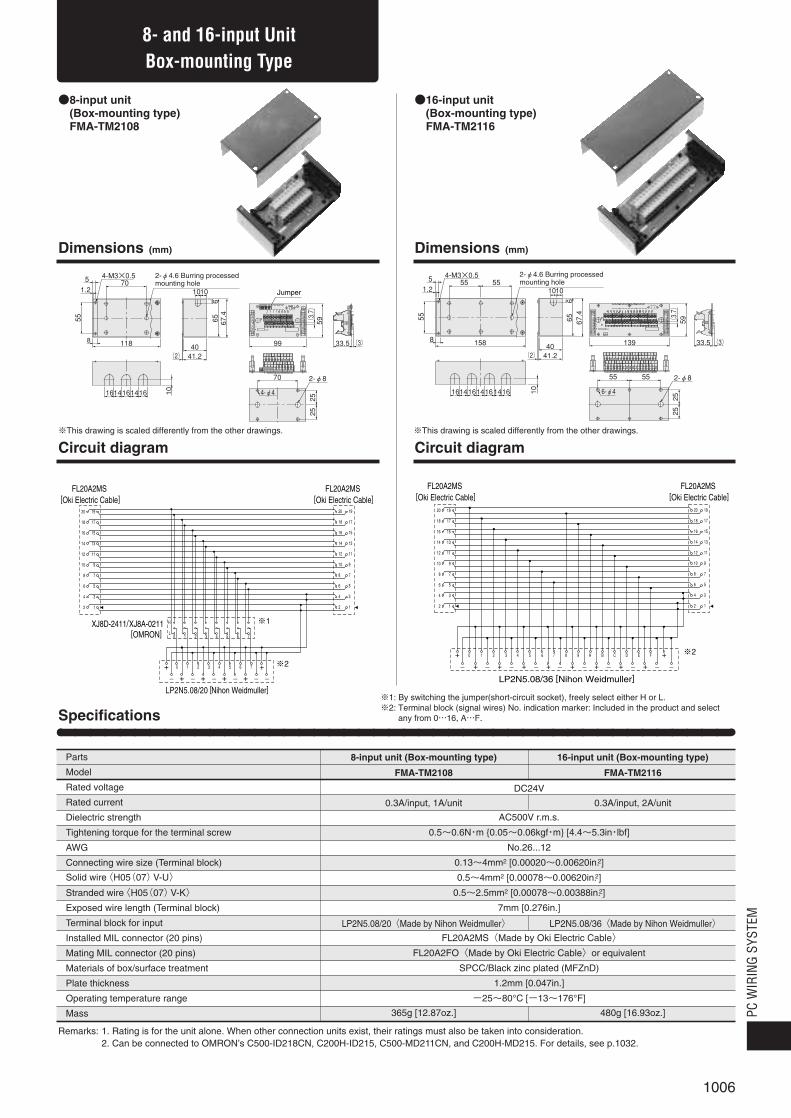
●8-input unit ●(Box-mounting type)●FMA-TM2108
●16-input unit ●(Box-mounting type)●FMA-TM2116
20�
18�
16�
14�
12�
10�
8�
6�
4�
2
19�
17�
15�
13�
11�
9�
7�
5�
3�
1
20�
18�
16�
14�
12�
10�
8�
6�
4�
2
19�
17�
15�
13�
11�
9�
7�
5�
3�
1
H
L0 1 2 3 4 5 6 7
0 1 2 3 4 5 6 7
–�++
–�+ –�+ –�+ –�–�+ ※2
※1
FL20A2MS [Oki Electric Cable]
LP2N5.08/20 [Nihon Weidmuller]
FL20A2MS [Oki Electric Cable]
XJ8D-2411/XJ8A-0211[OMRON]
20�
18�
16�
14�
12�
10�
8�
6�
4�
2
19�
17�
15�
13�
11�
9�
7�
5�
3�
1
20�
18�
16�
14�
12�
10�
8�
6�
4�
2
19�
17�
15�
13�
11�
9�
7�
5�
3�
1
0 1 2 3 4 5 6 7 8 9 A B C D E F
–�+ –�+ –�+ –�+ –�+ –�+ –�+ –�+ –� –�++ ※2
FL20A2MS [Oki Electric Cable]
LP2N5.08/36 [Nihon Weidmuller]
FL20A2MS [Oki Electric Cable]
33.5139
59
-�- +� -+� - +�- +� -- +�+� --� +� - +�
+�F�E�D�C�B�A�9�8�7�5� 6�4�2� 3�1�+� 0�
INOUT
1�
2�
C1�
C2�
-�
+�
CN1�
CN2�
CH
(3.7)�
(3)�158
55
8
667.4
10
40
161416 1614 1614
41.2(2)��
65
1.2
4-M3×0.55
101055 55
2525
55 55
6-φ4
2-φ8
2-φ4.6 Burring processed�mounting hole
※This drawing is scaled differently from the other drawings.
※1: By switching the jumper(short-circuit socket), freely select either H or L.※2: Terminal block (signal wires) No. indication marker: Included in the product and select
any from 0…16, A…F.
59
33.599118
55
8
1.2
4-M3×0.55
1010
667.4
10
2525
40
70
161416 1614
41.2(2)�
65
70
2-φ8
4-φ4
-�+� -�-�+�+�-� -�-� +�
+�7�5� 6�4�3�1� 2�0�+�
OUTIN
1� 2�
C1�L�
H�
0�1�2�3�4�5�6�7�
-�
+�
C2�
CN2�
CN1�
CH
(3.7)�
(3)�
2-φ4.6 Burring processedmounting hole
Jumper
※This drawing is scaled differently from the other drawings.
8- and 16-input Unit Box-mounting Type
Dimensions (mm) Dimensions (mm)
Circuit diagram Circuit diagram
8-input unit (Box-mounting type)
FMA-TM2108
0.3A/input, 1A/unit
LP2N5.08/20〈Made by Nihon Weidmuller〉
365g [12.87oz.]
16-input unit (Box-mounting type)
FMA-TM2116
0.3A/input, 2A/unit
LP2N5.08/36〈Made by Nihon Weidmuller〉
480g [16.93oz.]
Specifications
Parts
Model
Rated voltage
Rated current
Dielectric strength
Tightening torque for the terminal screw
AWG
Connecting wire size (Terminal block)
Solid wire〈H05(07)V-U〉
Stranded wire〈H05(07)V-K〉
Exposed wire length (Terminal block)
Terminal block for input
Installed MIL connector (20 pins)
Mating MIL connector (20 pins)
Materials of box/surface treatment
Plate thickness
Operating temperature range
Mass
DC24V
AC500V r.m.s.
0.5~0.6N・m {0.05~0.06kgf・m} [4.4~5.3in・lbf]
No.26...12
0.13~4mm2 [0.00020~0.00620in.2]
0.5~4mm2 [0.00078~0.00620in.2]
0.5~2.5mm2 [0.00078~0.00388in.2]
7mm [0.276in.]
FL20A2MS〈Made by Oki Electric Cable〉
FL20A2FO〈Made by Oki Electric Cable〉or equivalent
SPCC/Black zinc plated (MFZnD)
1.2mm [0.047in.]
-25~80°C [-13~176°F]
Remarks: 1. Rating is for the unit alone. When other connection units exist, their ratings must also be taken into consideration.2. Can be connected to OMRON’s C500-ID218CN, C200H-ID215, C500-MD211CN, and C200H-MD215. For details, see p.1032.

1007
5553.5
28.3
45
103
4.5
16.7
55
CH
-�+� +�+� +�+� +�+� +�-�
+�7�6�4� 5�3�2�0�+�
CN2�CN1�
H�L�
7�6�5�4�3�2�1�0�
+�
-�
1�
2�
3�
4�
C�
1
RS-
10.5 10.5
4.1
5.1(3.7)�Jumper 55
53.5
28.3
45
103
16.7OUT
CN1
RS-
CH
F�
+� +�
E�D�
+� +�
C�B�
+� +�
A�9�
+� +�
8�7�
+� +�
6�5�
+� +�
4�3�
+� +�
2�1�0�
+� +�-�
+�
4.5
10.5 10.5
(3.7)� 5.1
4.1
55
●8-output unit (DIN rail mounting type)●FMA-TM1008
●16-output unit (DIN rail mounting type)●FMA-TM1016
20�
18�
16�
14�
12�
10�
8�
6�
4�
2
19�
17�
15�
13�
11�
9�
7�
5�
3�
1
20�
18�
16�
14�
12�
10�
8�
6�
4�
2
19�
17�
15�
13�
11�
9�
7�
5�
3�
1
H
L0 1 2 3 4 5 6 7
0 1 2 3 4 5 6 7
–�+ + + + + + + ++
–�+ ※2
※1
FL20A2MS [Oki Electric Cable]
LP2N5.08/20 [Nihon Weidmuller]
FL20A2MS [Oki Electric Cable]
XJ8D-2411/XJ8A-0211[OMRON]
20�
18�
16�
14�
12�
10�
8�
6�
4�
2
19�
17�
15�
13�
11�
9�
7�
5�
3�
1
0 1 2 3 4 5 6 7 8 9 A B C D E F
–�+ + + + + + + + + + + + + + + ++ ※2
LP2N5.08/34 [Nihon Weidmuller]
FL20A2MS[Oki Electric Cable]
※1: By switching the jumper (short-circuit socket), freely select either H or L.※2: Terminal block (signal wires) No. indication marker: Included in the product and select
any from 0…16, A…F.
Dimensions (mm) Dimensions (mm)
Circuit diagram Circuit diagram
8- and 16-output UnitDIN Rail Mounting Type
8-output unit (DIN rail mounting type)
FMA-TM1008
0.3A/output, 1A/unit
LP2N5.08/20〈Made by Nihon Weidmuller〉
105g [3.70oz.]
16-output unit (DIN rail mounting type)
FMA-TM1016
0.3A/output, 2A/unit
LP2N5.08/34〈Made by Nihon Weidmuller〉
125g [4.41oz.]
Specifications
Parts
Model
Rated voltage
Rated current
Dielectric strength
Tightening torque for the terminal screw
AWG
Connecting wire size (Terminal block)
Solid wire〈H05(07)V-U〉
Stranded wire〈H05(07)V-K〉
Exposed wire length (Terminal block)
Terminal block for output
Installed MIL connector (20 pins)
Mating MIL connector (20 pins)
Operating temperature range
Mass
DC24V
AC500V r.m.s.
0.5~0.6N・m {0.05~0.06kgf・m} [4.4~5.3in・lbf]
No.26...12
0.13~4mm2 [0.00020~0.00620in.2]
0.5~4mm2 [0.00078~0.00620in.2]
0.5~2.5mm2 [0.00078~0.00388in.2]
7mm [0.276in.]
FL20A2MS〈Made by Oki Electric Cable〉
FL20A2FO〈Made by Oki Electric Cable〉or equivalent
-25~80°C [-13~176°F]
Remarks: 1. Rating is for the unit alone. When other connection units exist, their ratings must also be taken into consideration.2. Can be connected to OMRON’s C500-OD415CN, C200H-OD215, C500-MD211CN, and C200H-MD215. For details, see p.1032.

1008
PC W
IRIN
G SY
STEM
●8-output unit ●(Box-mounting type)●FMA-TM2008
●16-output unit ●(Box-mounting type)●FMA-TM2016
20�
18�
16�
14�
12�
10�
8�
6�
4�
2
19�
17�
15�
13�
11�
9�
7�
5�
3�
1
20�
18�
16�
14�
12�
10�
8�
6�
4�
2
19�
17�
15�
13�
11�
9�
7�
5�
3�
1
H
L0 1 2 3 4 5 6 7
0 1 2 3 4 5 6 7
–�+ + + + + + + ++
–�+ ※2
※1
FL20A2MS [Oki Electric Cable]
LP2N5.08/20 [Nihon Weidmuller]
FL20A2MS [Oki Electric Cable]
XJ8D-2411/XJ8A-0211[OMRON]
20�
18�
16�
14�
12�
10�
8�
6�
4�
2
19�
17�
15�
13�
11�
9�
7�
5�
3�
1
20�
18�
16�
14�
12�
10�
8�
6�
4�
2
19�
17�
15�
13�
11�
9�
7�
5�
3�
1
0 1 2 3 4 5 6 7 8 9 A B C D E F
–�+ + + + + + + + + + + + + + + + –�++ ※2
FL20A2MS [Oki Electric Cable]
LP2N5.08/36 [Nihon Weidmuller]
FL20A2MS [Oki Electric Cable]
33.5139
59
-�+� +�+� +� +� +�+� +�+� +�+� +�-� +� +� +� +�
+�F�E�D�C�B�A�9�8�7�5� 6�4�2� 3�1�+� 0�
OUT
1�
2�
C1�
C2�
-�
+�
CN1�
CN2�
CH
(3.7)�
(3)�158
55
8
667.4
10
40
161416 1614 1614
41.2(2)��
65
1.2
4-M3×0.55
101055 55
2525
55 55
6-φ4
2-φ8
2-φ4.6 Burring processedmounting hole
※This drawing is scaled differently from the other drawings.
※1: By switching the jumper(short-circuit socket), freely select either H or L.※2: Terminal block (signal wires) No. indication marker: Included in the product and select
any from 0…16, A…F.
59
33.599118
55
8
1.2
4-M3×0.55
1010
667.4
10
2525
40
70
161416 1614
41.2(2)�
65
70
2-φ8
4-φ4
-�+� +�+� +�+� +�-� +� +�
+�7�5� 6�4�3�1� 2�0�+�
OUT
1� 2�
C1�L�
H�
0�1�2�3�4�5�6�7�
-�
+�
C2�
CN2�
CN1�
CH
(3.7)�
(3)�
2-φ4.6 Burring processedmounting hole
Jumper
※This drawing is scaled differently from the other drawings.
Dimensions (mm) Dimensions (mm)
Circuit diagram Circuit diagram
8- and 16-output UnitBox-mounting Type
8-output unit (Box-mounting type)
FMA-TM2008
0.3A/output, 1A/unit
LP2N5.08/20〈Made by Nihon Weidmuller〉
365g [12.87oz.]
16-output unit (Box-mounting type)
FMA-TM2016
0.3A/output, 2A/unit
LP2N5.08/36〈Made by Nihon Weidmuller〉
480g [16.93oz.]
Parts
Model
Rated voltage
Rated current
Dielectric strength
Tightening torque for the terminal screw
AWG
Connecting wire size (Terminal block)
Solid wire〈H05(07)V-U〉
Stranded wire〈H05(07)V-K〉
Exposed wire length (Terminal block)
Terminal block for output
Installed MIL connector (20 pins)
Mating MIL connector (20 pins)
Materials of box/surface treatment
Plate thickness
Operating temperature range
Mass
DC24V
AC500V r.m.s.
0.5~0.6N・m {0.05~0.06kgf・m} [4.4~5.3in・lbf]
No.26...12
0.13~4mm2 [0.00020~0.00620in.2]
0.5~4mm2 [0.00078~0.00620in.2]
0.5~2.5mm2 [0.00078~0.00388in.2]
7mm [0.276in.]
FL20A2MS〈Made by Oki Electric Cable〉
FL20A2FO〈Made by Oki Electric Cable〉or equivalent
SPCC/Black zinc plated (MFZnD)
1.2mm [0.047in.]
-25~80°C [-13~176°F]
Remarks: 1. Rating is for the unit alone. When other connection units exist, their ratings must also be taken into consideration.2. Can be connected to OMRON’s C500-OD415CN, C200H-OD215, C500-MD211CN, and C200H-MD215. For details, see p.1032.
Specifications
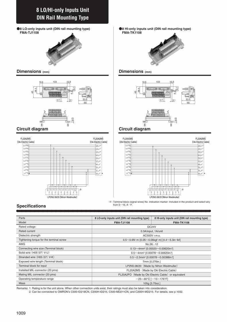
1009
8 LO/HI-only Inputs Unit
5553.5
28.3
45
103
4.5
16.7
55
CH
-�-�-� +�-� +�-� +�+�-�
+�7�6�4� 5�3�2�0�+�
CN2�CN1�
+�
-�
1�
2�
3�
4�
C�
1
RS-
10.5 10.5
4.1
5.1(3.7)�5553.5
28.3
45
103
4.5
16.7
55
CH
-�-�-� +�-� +�-� +�+�-�
+�FEC DBA8+�
CN2�CN1�
+�
-�
1�
2�
3�
4�
C�
9
RS-
10.5 10.5
4.1
5.1(3.7)�
●8 LO-only inputs unit (DIN rail mounting type)●FMA-TJ1108
●8 HI-only inputs unit (DIN rail mounting type)●FMA-TK1108
20�
18�
16�
14�
12�
10�
8�
6�
4�
2
19�
17�
15�
13�
11�
9�
7�
5�
3�
1
20�
18�
16�
14�
12�
10�
8�
6�
4�
2
19�
17�
15�
13�
11�
9�
7�
5�
3�
1
0 1 2 3 4 5 6 7
–�++
–�+ –�+ –�+ –�–�+ ※�
FL20A2MS [Oki Electric Cable]
LP2N5.08/20 [Nihon Weidmuller]
FL20A2MS [Oki Electric Cable]
20�
18�
16�
14�
12�
10�
8�
6�
4�
2
19�
17�
15�
13�
11�
9�
7�
5�
3�
1
20�
18�
16�
14�
12�
10�
8�
6�
4�
2
19�
17�
15�
13�
11�
9�
7�
5�
3�
1
8 9 A B C D E F
–�++
–�+ –�+ –�+ –�–�+ ※�
FL20A2MS [Oki Electric Cable]
LP2N5.08/20 [Nihon Weidmuller]
FL20A2MS [Oki Electric Cable]
DIN Rail Mounting Type
Dimensions (mm) Dimensions (mm)
Circuit diagram Circuit diagram
※ : Terminal block (signal wires) No. indication marker: Included in the product and select anyfrom 0…16, A…F.
8 HI-only inputs unit (DIN rail mounting type)
FMA-TK1108
DC24V
0.3A/input, 1A/unit
AC500V r.m.s.
0.5~0.6N・m {0.05~0.06kgf・m} [4.4~5.3in・lbf]
No.26...12
0.13~4mm2 [0.00020~0.00620in.2]
0.5~4mm2 [0.00078~0.00620in.2]
0.5~2.5mm2 [0.00078~0.00388in.2]
7mm [0.276in.]
LP2N5.08/20〈Made by Nihon Weidmuller〉
FL20A2MS〈Made by Oki Electric Cable〉
FL20A2FO〈Made by Oki Electric Cable〉or equivalent
-25~80°C [-13~176°F]
105g [3.70oz.]
8 LO-only inputs unit (DIN rail mounting type)
FMA-TJ1108
Specifications
Parts
Model
Rated voltage
Rated current
Dielectric strength
Tightening torque for the terminal screw
AWG
Connecting wire size (Terminal block)
Solid wire〈H05(07)V-U〉
Stranded wire〈H05(07)V-K〉
Exposed wire length (Terminal block)
Terminal block for input
Installed MIL connector (20 pins)
Mating MIL connector (20 pins)
Operating temperature range
Mass
Remarks: 1. Rating is for the unit alone. When other connection units exist, their ratings must also be taken into consideration.2. Can be connected to OMRON’s C500-ID218CN, C200H-ID215, C500-MD211CN, and C200H-MD215. For details, see p.1032.

1010
PC W
IRIN
G SY
STEM
59
33.599118
55
8
1.2
4-M3×0.55
1010
667.4
10
2525
40
70
161416 1614
41.2(2)�
65
70
2-φ8
4-φ4
-�+� -�-�+�+�-� -�-� +�
+�7�5� 6�4�3�1� 2�0�+�
OUTIN
1� 2�
C1�
-�
+�
C2�
CN2�
CN1�
CH
(3.7)�
(3)�
2-φ4.6 Burring processedmounting hole
●8 LO-only inputs unit (Box-mounting type)●FMA-TJ2108
●8 HI-only inputs unit (Box-mounting type)●FMA-TK2108
8 LO/HI-only Inputs UnitBox-mounting Type
Dimensions (mm) Dimensions (mm)
Circuit diagram Circuit diagram※This drawing is scaled differently from the other drawings.
59
33.599118
55
8
1.2
4-M3×0.55
1010
667.4
10
2525
40
70
161416 1614
41.2(2)�
65
70
2-φ8
4-φ4
-�+� -�-�+�+�-� -�-� +�
+�FD ECB9 A8+�
OUTIN
1� 2�
C1�
-�
+�
C2�
CN2�
CN1�
CH
(3.7)�
(3)�
2-φ4.6 Burring processedmounting hole
※This drawing is scaled differently from the other drawings.
20�
18�
16�
14�
12�
10�
8�
6�
4�
2
19�
17�
15�
13�
11�
9�
7�
5�
3�
1
20�
18�
16�
14�
12�
10�
8�
6�
4�
2
19�
17�
15�
13�
11�
9�
7�
5�
3�
1
0 1 2 3 4 5 6 7
–�++
–�+ –�+ –�+ –�–�+ ※�
FL20A2MS [Oki Electric Cable]
LP2N5.08/20 [Nihon Weidmuller]
FL20A2MS [Oki Electric Cable]
20�
18�
16�
14�
12�
10�
8�
6�
4�
2
19�
17�
15�
13�
11�
9�
7�
5�
3�
1
20�
18�
16�
14�
12�
10�
8�
6�
4�
2
19�
17�
15�
13�
11�
9�
7�
5�
3�
1
8 9 A B C D E F
–�++
–�+ –�+ –�+ –�–�+ ※�
FL20A2MS [Oki Electric Cable]
LP2N5.08/20 [Nihon Weidmuller]
FL20A2MS [Oki Electric Cable]
※ : Terminal block (signal wires) No. indication marker: Included in the product and select anyfrom 0…16, A…F.
8 LO-only inputs unit (Box-mounting type)
FMA-TJ2108
8 HI-only inputs unit (Box-mounting type)
FMA-TK2108
Specifications
Parts
Model
Rated voltage
Rated current
Dielectric strength
Tightening torque for the terminal screw
AWG
Connecting wire size (Terminal block)
Solid wire〈H05(07)V-U〉
Stranded wire〈H05(07)V-K〉
Exposed wire length (Terminal block)
Terminal block for input
Installed MIL connector (20 pins)
Mating MIL connector (20 pins)
Materials of box/surface treatment
Plate thickness
Operating temperature range
Mass
DC24V
0.3A/input, 1A/unit
AC500V r.m.s.
0.5~0.6N・m {0.05~0.06kgf・m} [4.4~5.3in・lbf]
No.26...12
0.13~4mm2 [0.00020~0.00620in.2]
0.5~4mm2 [0.00078~0.00620in.2]
0.5~2.5mm2 [0.00078~0.00388in.2]
7mm [0.276in.]
LP2N5.08/20〈Made by Nihon Weidmuller〉
FL20A2MS〈Made by Oki Electric Cable〉
FL20A2FO〈Made by Oki Electric Cable〉or equivalent
SPCC/Black zinc plated (MFZnD)
1.2mm [0.047in.]
-25~80°C [-13~176°F]
365g [12.87oz.]
Remarks: 1. Rating is for the unit alone. When other connection units exist, their ratings must also be taken into consideration.2. Can be connected to OMRON’s C500-ID218CN, C200H-ID215, C500-MD211CN, and C200H-MD215. For details, see p.1032.
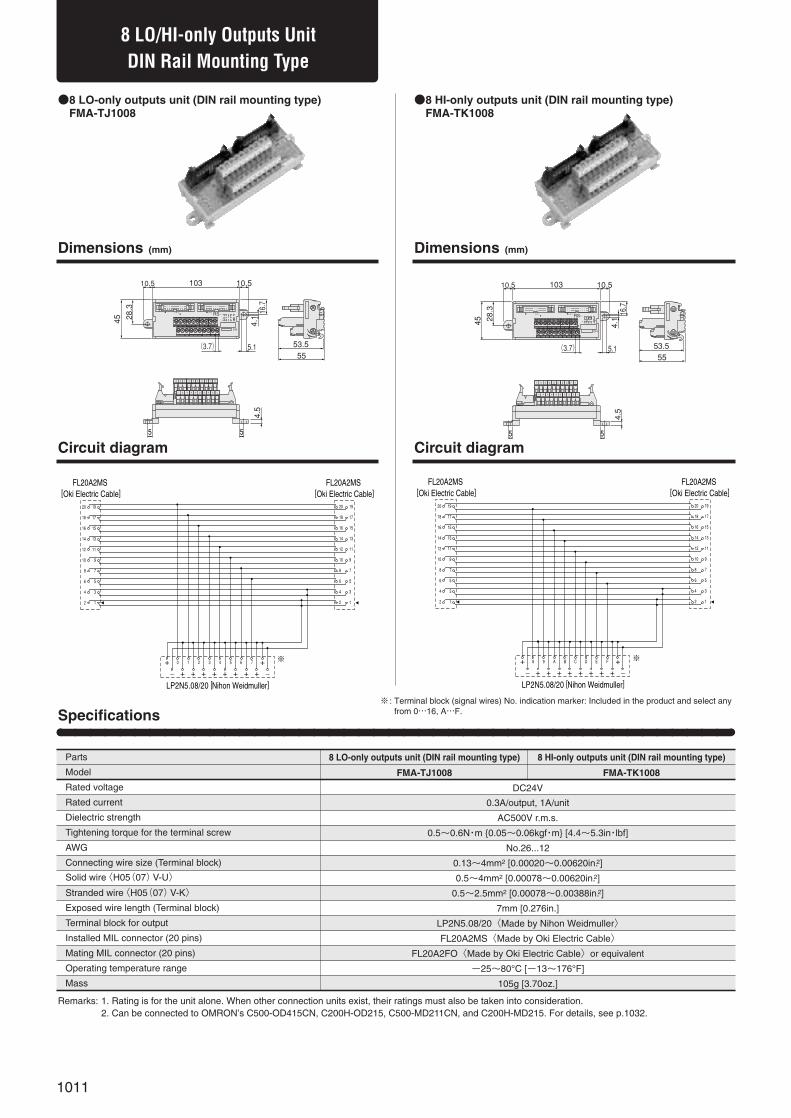
1011
5553.5
28.3
45
103
4.5
16.7
55
CH
-�+� +�+� +�+� +�+� +�-�
+�7�6�4� 5�3�2�0�+�
CN2�CN1�
+�
-�
1�
2�
3�
4�
C�
1
RS-
10.5 10.5
4.1
5.1(3.7)�5553.5
28.3
45
103
4.5
16.7
55
CH
-�+� +�+� +�+� +�+� +�-�
+�FEC DBA8+�
CN2�CN1�
+�
-�
1�
2�
3�
4�
C�
9
RS-
10.5 10.5
4.1
5.1(3.7)�
●8 LO-only outputs unit (DIN rail mounting type)●FMA-TJ1008
●8 HI-only outputs unit (DIN rail mounting type)●FMA-TK1008
20�
18�
16�
14�
12�
10�
8�
6�
4�
2
19�
17�
15�
13�
11�
9�
7�
5�
3�
1
20�
18�
16�
14�
12�
10�
8�
6�
4�
2
19�
17�
15�
13�
11�
9�
7�
5�
3�
1
0 1 2 3 4 5 6 7
–�+ + + + + + + ++
–�+ ※�
FL20A2MS [Oki Electric Cable]
LP2N5.08/20 [Nihon Weidmuller]
FL20A2MS [Oki Electric Cable]
20�
18�
16�
14�
12�
10�
8�
6�
4�
2
19�
17�
15�
13�
11�
9�
7�
5�
3�
1
20�
18�
16�
14�
12�
10�
8�
6�
4�
2
19�
17�
15�
13�
11�
9�
7�
5�
3�
1
8 9 A B C D E F
–�+ + + + + + + ++
–�+ ※�
FL20A2MS [Oki Electric Cable]
LP2N5.08/20 [Nihon Weidmuller]
FL20A2MS [Oki Electric Cable]
8 LO/HI-only Outputs UnitDIN Rail Mounting Type
Dimensions (mm) Dimensions (mm)
Circuit diagram Circuit diagram
※ : Terminal block (signal wires) No. indication marker: Included in the product and select anyfrom 0…16, A…F.
8 HI-only outputs unit (DIN rail mounting type)
FMA-TK1008
DC24V
0.3A/output, 1A/unit
AC500V r.m.s.
0.5~0.6N・m {0.05~0.06kgf・m} [4.4~5.3in・lbf]
No.26...12
0.13~4mm2 [0.00020~0.00620in.2]
0.5~4mm2 [0.00078~0.00620in.2]
0.5~2.5mm2 [0.00078~0.00388in.2]
7mm [0.276in.]
LP2N5.08/20〈Made by Nihon Weidmuller〉
FL20A2MS〈Made by Oki Electric Cable〉
FL20A2FO〈Made by Oki Electric Cable〉or equivalent
-25~80°C [-13~176°F]
105g [3.70oz.]
8 LO-only outputs unit (DIN rail mounting type)
FMA-TJ1008
Specifications
Parts
Model
Rated voltage
Rated current
Dielectric strength
Tightening torque for the terminal screw
AWG
Connecting wire size (Terminal block)
Solid wire〈H05(07)V-U〉
Stranded wire〈H05(07)V-K〉
Exposed wire length (Terminal block)
Terminal block for output
Installed MIL connector (20 pins)
Mating MIL connector (20 pins)
Operating temperature range
Mass
Remarks: 1. Rating is for the unit alone. When other connection units exist, their ratings must also be taken into consideration.2. Can be connected to OMRON’s C500-OD415CN, C200H-OD215, C500-MD211CN, and C200H-MD215. For details, see p.1032.

1012
PC W
IRIN
G SY
STEM
59
33.599118
55
8
1.2
4-M3×0.55
1010
667.4
10
2525
40
70
161416 1614
41.2(2)�
65
70
2-φ8
4-φ4
-�+� +�+� +�+� +�-� +� +�
+�7�5� 6�4�3�1� 2�0�+�
OUT
1� 2�
C1�
-�
+�
C2�
CN2�
CN1�
CH
(3.7)�
(3)�
2-φ4.6 Burring processedmounting hole
●8 LO-only outputs unit ●(Box-mounting type)●FMA-TJ2008
●8 HI-only outputs unit ●(Box-mounting type)●FMA-TK2008
8 LO/HI-only Outputs UnitBox-mounting Type
Dimensions (mm) Dimensions (mm)
Circuit diagram Circuit diagram※This drawing is scaled differently from the other drawings.
59
33.599118
55
8
1.2
4-M3×0.55
1010
667.4
10
2525
40
70
161416 1614
41.2(2)�
65
70
2-φ8
4-φ4
-�+� +�+� +�+� +�-� +� +�
+�FD ECB9 A8+�
OUT
1� 2�
C1�
-�
+�
C2�
CN2�
CN1�
CH
(3.7)�
(3)�
2-φ4.6 Burring processedmounting hole
※This drawing is scaled differently from the other drawings.
※ : Terminal block (signal wires) No. indication marker: Included in the product and select anyfrom 0…16, A…F.
20�
18�
16�
14�
12�
10�
8�
6�
4�
2
19�
17�
15�
13�
11�
9�
7�
5�
3�
1
20�
18�
16�
14�
12�
10�
8�
6�
4�
2
19�
17�
15�
13�
11�
9�
7�
5�
3�
1
0 1 2 3 4 5 6 7
–�+ + + + + + + ++
–�+ ※�
FL20A2MS [Oki Electric Cable]
LP2N5.08/20 [Nihon Weidmuller]
FL20A2MS [Oki Electric Cable]
20�
18�
16�
14�
12�
10�
8�
6�
4�
2
19�
17�
15�
13�
11�
9�
7�
5�
3�
1
20�
18�
16�
14�
12�
10�
8�
6�
4�
2
19�
17�
15�
13�
11�
9�
7�
5�
3�
1
8 9 A B C D E F
–�+ + + + + + + ++
–�+ ※�
FL20A2MS [Oki Electric Cable]
LP2N5.08/20 [Nihon Weidmuller]
FL20A2MS [Oki Electric Cable]
Specifications
8 LO-only outputs unit (Box-mounting type)
FMA-TJ2008
8 HI-only outputs unit (Box-mounting type)
FMA-TK2008
Parts
Model
Rated voltage
Rated current
Dielectric strength
Tightening torque for the terminal screw
AWG
Connecting wire size (Terminal block)
Solid wire〈H05(07)V-U〉
Stranded wire〈H05(07)V-K〉
Exposed wire length (Terminal block)
Terminal block for output
Installed MIL connector (20 pins)
Mating MIL connector (20 pins)
Materials of box/surface treatment
Plate thickness
Operating temperature range
Mass
DC24V
0.3A/output, 1A/unit
AC500V r.m.s.
0.5~0.6N・m {0.05~0.06kgf・m} [4.4~5.3in・lbf]
No.26...12
0.13~4mm2 [0.00020~0.00620in.2]
0.5~4mm2 [0.00078~0.00620in.2]
0.5~2.5mm2 [0.00078~0.00388in.2]
7mm [0.276in.]
LP2N5.08/20〈Made by Nihon Weidmuller〉
FL20A2MS〈Made by Oki Electric Cable〉
FL20A2FO〈Made by Oki Electric Cable〉 or equivalent
SPCC/Black zinc plated (MFZnD)
1.2mm [0.047in.]
-25~80°C [-13~176°F]
365g [12.87oz.]
Remarks: 1. Rating is for the unit alone. When other connection units exist, their ratings must also be taken into consideration.2. Can be connected to OMRON’s C500-OD415CN, C200H-OD215, C500-MD211CN, and C200H-MD215. For details, see p.1032.

1013
Connector Type 8-input UnitDIN Rail Mounting Type
10.5 103 10.5
28.3
4.116.7
5.1
45
49
50.5
4.5
55
CN-0 CN-1 CN-2 CN-3 CN-4 CN-5 CN-6 CN-7
INCN-PC1
1 2 3
+ S -�
CN-PS1 CN-PS2
CN-PC2
RS
RS
CN-0(8) CN-1(9) CN-2(A) CN-3(B)CN-4(C) CN-5(D) CN-6(E) CN-7(F)
I NCN-PC1
1 2 3
+ S -�
CN-PS
H�L
10.5 69 10.5
28.3
4.116.7
5.1
45
49
50.5
4.5
55
●Connector type 8-input unit〔main unit〕●(DIN rail mounting type)●FMA-TC1108
●Connector type 8-input unit〔sub-unit〕●(DIN rail mounting type)●FMA-TD1108
CN-PS 1 CN-PS 2
CN-0 CN-1 CN-2 CN-3 CN-4 CN-5 CN-6 CN-7
CN-PC 1 CN-PC 2135791113151719
2468101214161820
135791113151719
2468101214161820
�
�
+�
-�
▼� ▼�
+�
-�
1 2 3
+�S -�
FL20A2MS [Oki Electric Cable]
Wafer53375-0310
[Molex Japan]
LPA1/2 [Nihon Weidmuller]
CN-PS
CN-PC 1135791113151719
2468101214161820
+�
-�
▼�
CN-0(8) CN-1(9) CN-2(A) CN-3(B) CN-4(C) CN-5(D) CN-6(E) CN-7(F)
1 2 3
+�S -�
FL20A2MS [Oki Electric Cable] LPA1/2
[Nihon Weidmuller]
Wafer53375-0310
[Molex Japan]※Jumper (short circuit socket) cannot be switched.
Dimensions (mm) Dimensions (mm)
Circuit diagram Circuit diagram
Connector type 8-input unit (sub-unit)
FMA-TD1108
55g [1.94oz.]
DC24V
0.3A/input, 1A/unit
AC500V r.m.s.
0.4~0.6N・m {0.04~0.06kgf・m} [3.5~5.3in・lbf]
No.26...14
0.13~2.5mm2 [0.00020~0.00388in.2]
0.5~2.5mm2 [0.00078~0.00388in.2]
0.5~2.5mm2 [0.00078~0.00388in.2]
7mm [0.276in.]
LPA1/2〈Made by Nihon Weidmuller〉
FL20A2MS〈Made by Oki Electric Cable〉
FL20A2FO〈Made by Oki Electric Cable〉or equivalent
53375-0310〈Made by Molex Japan〉
51103-0300〈Made by Molex Japan〉
50351-8100〈Made by Molex Japan〉● Applicable wire Lead wire size: AWG No.28...22 Insulation outer diameter:φ1.15~φ1.8mm [φ0.0453~φ0.071in.]
Exposed wire length: 2.3~2.8mm [0.091~0.110in.]
-25~80°C [-13~176°F]
Connector type 8-input unit (main unit)
FMA-TC1108
75g [2.65oz.]
Specifications
Parts
Model
Rated voltage
Rated current
Dielectric strength
Tightening torque for the terminal screw
AWG
Connecting wire size (Terminal block)
Power supply Solid wire〈H05 (07) V-U〉
terminal Stranded wire〈H05 (07) V-K〉
Exposed wire length (Terminal block)
Installed terminal block (For power supply)
Installed MIL connector (20 pins)
Mating MIL connector (20 pins)
Installed wafer (3 pins)
Mating housing (3 pins)
Mating terminal
Operating temperature range
Mass
Remarks: 1. Rating is for the unit alone. When other connection units exist, their ratings must also be taken into consideration.2. Can be connected to OMRON’s C500-ID218CN, C200H-ID215, C500-MD211CN, and C200H-MD215. For details, see p.1032.3. For details of applicable mating housings and terminals, see p.994.

1014
PC W
IRIN
G SY
STEM
10.5 103 10.5
28.3
4.116.7
5.1
45
49
50.5
4.5
55
I N
RSCN-0 CN-1 CN-2 CN-3 CN-4 CN-5 CN-6 CN-7
CN-PC
1 2 3
+ S -�
CN-8 CN-9 CN-A CN-B CN-C CN-D CN-E CN-F
CN-PS
●Connector type 16-input unit (DIN rail mounting type)●FMA-TC1116
CN-PS
CN-8 CN-9 CN-A CN-B CN-C CN-D CN-E CN-F
CN-0 CN-1 CN-2 CN-3 CN-4 CN-5 CN-6 CN-7
CN-PC135791113151719
2468101214161820``
+�
-�
▼�
1 2 3
+�S -�
FL20A2MS [Oki Electric Cable]
LPA1/2 [Nihon Weidmuller]
Wafer53375-0310
[Molex Japan]
Connector Type 16-input UnitDIN Rail Mounting Type
Dimensions (mm)
Circuit diagram
Connector type 16-input unit
FMA-TC1116
DC24V
0.3A/input, 2A/unit
AC500V r.m.s.
0.4~0.6N・m {0.04~0.06kgf・m} [3.5~5.3in・lbf]
No.26...14
0.13~2.5mm2 [0.00020~0.00388in.2]
0.5~2.5mm2 [0.00078~0.00388in.2]
0.5~2.5mm2 [0.00078~0.00388in.2]
7mm [0.276in.]
LPA1/2〈Made by Nihon Weidmuller〉
FL20A2MS〈Made by Oki Electric Cable〉
FL20A2FO〈Made by Oki Electric Cable〉or equivalent
53375-0310〈Made by Molex Japan〉
51103-0300〈Made by Molex Japan〉
50351-8100〈Made by Molex Japan〉● Applicable wire Lead wire size: AWG No.28...22 Insulation outer diameter:φ1.15~φ1.8mm [φ0.0453~φ0.071in.]
Exposed wire length: 2.3~2.8mm [0.091~0.110in.]
-25~80°C [-13~176°F]
70g [2.47oz.]
Specifications
Parts
Model
Rated voltage
Rated current
Dielectric strength
Tightening torque for the terminal screw
AWG
Connecting wire size (Terminal block)
Power supply Solid wire〈H05 (07) V-U〉
terminal Stranded wire〈H05 (07) V-K〉
Exposed wire length (Terminal block)
Installed terminal block (For power supply)
Installed MIL connector (20 pins)
Mating MIL connector (20 pins)
Installed wafer (3 pins)
Mating housing (3 pins)
Mating terminal
Operating temperature range
Mass
Remarks: 1. Rating is for the unit alone. When other connection units exist, their ratings must also be taken into consideration.2. Can be connected to OMRON’s C500-ID218CN, C200H-ID215, C500-MD211CN, and C200H-MD215. For details, see p.1032.3. For details of applicable mating housings and terminals, see p.994.

1015
10.5 103 10.5
28.3
4.116.7
5.1
45
49
50.5
4.5
55
RSCN-0 CN-1 CN-2 CN-3 CN-4 CN-5 CN-6 CN-7
OUTCN-PC1
1 2 3
+ S -�
CN-PS1 CN-PS2
CN-PC2
10.5 69 10.5
28.3
4.116.7
5.1
45
49
50.5
4.5
55
CN-0(8) CN-1(9) CN-2(A) CN-3(B)CN-4(C) CN-5(D) CN-6(E) CN-7(F)
OUT CN-PC1
1 2 3
+ S -�
CN-PS
H�L
RS
●Connector type 8-output unit〔main unit〕●(DIN rail mounting type)●FMA-TC1008
●Connector type 8-output unit〔sub-unit〕●(DIN rail mounting type)●FMA-TD1008
CN-PS 1 CN-PS 2
CN-0 CN-1 CN-2 CN-3 CN-4 CN-5 CN-6 CN-7
CN-PC 1 CN-PC 2135791113151719
2468101214161820
135791113151719
2468101214161820
�
�
+�
-�
▼� ▼�
+�
-�
1 2 3
+�S -�
FL20A2MS [Oki Electric Cable]LPA1/2
[Nihon Weidmuller]
Wafer53375-0310
[Molex Japan]
CN-PS
CN-0(8) CN-1(9) CN-2(A) CN-3(B) CN-4(C) CN-5(D) CN-6(E) CN-7(F)
CN-PC 1135791113151719
2468101214161820
+�
-�
▼�
1 2 3
+�S -�
FL20A2MS [Oki Electric Cable] LPA1/2
[Nihon Weidmuller]
Wafer53375-0310
[Molex Japan]※Jumper (short circuit socket) cannot be switched.
Connector Type 8-output UnitDIN Rail Mounting Type
Dimensions (mm) Dimensions (mm)
Circuit diagram Circuit diagram
Connector type 8-output unit (sub-unit)
FMA-TD1008
55g [1.94oz.]
DC24V
0.3A/output, 1A/unit
AC500V r.m.s.
0.4~0.6N・m {0.04~0.06kgf・m} [3.5~5.3in・lbf]
No.26...14
0.13~2.5mm2 [0.00020~0.00388in.2]
0.5~2.5mm2 [0.00078~0.00388in.2]
0.5~2.5mm2 [0.00078~0.00388in.2]
7mm [0.276in.]
LPA1/2〈Made by Nihon Weidmuller〉
FL20A2MS〈Made by Oki Electric Cable〉
FL20A2FO〈Made by Oki Electric Cable〉or equivalent
53375-0310〈Made by Molex Japan〉
51103-0300〈Made by Molex Japan〉
50351-8100〈Made by Molex Japan〉● Applicable wire Core wire size: AWG No.28...22 Insulation outer diameter:φ1.15~φ1.8mm [φ0.0453~φ0.071in.]
Exposed wire length: 2.3~2.8mm [0.091~0.110in.]
-25~80°C [-13~176°F]
Connector type 8-output unit (main unit)
FMA-TC1008
75g [2.65oz.]
Specifications
Parts
Model
Rated voltage
Rated current
Dielectric strength
Tightening torque for the terminal screw
AWG
Power Connecting wire size (Terminal block)
supply Solid wire〈H05 (07) V-U〉
terminal Stranded wire〈H05 (07) V-K〉
Exposed wire length (Terminal block)
Installed terminal block (For power supply)
Installed MIL connector (20 pins)
Mating MIL connector (20 pins)
Installed wafer (3 pins)
Mating housing (3 pins)
Mating terminal
Operating temperature range
Mass
Remarks: 1. Rating is for the unit alone. When other connection units exist, their ratings must also be taken into consideration.2. Can be connected to OMRON’s C500-OD415CN, C200H-OD215, C500-MD211CN, and C200H-MD215. For details, see p.1032.3. For details of applicable mating housings and terminals, see p.994.

1016
PC W
IRIN
G SY
STEM
10.5 103 10.5
28.3
4.116.7
5.1
45
49
50.5
4.5
55
RSCN-0 CN-1 CN-2 CN-3 CN-4 CN-5 CN-6 CN-7
OUTCN-PC
1 2 3
+ S -�
CN-8 CN-9 CN-A CN-B CN-C CN-D CN-E CN-F
CN-PS
●Connector type 16-output unit (DIN rail mounting type)●FMA-TC1016
CN-PS
CN-8 CN-9 CN-A CN-B CN-C CN-D CN-E CN-F
CN-0 CN-1 CN-2 CN-3 CN-4 CN-5 CN-6 CN-7
CN-PC135791113151719
2468101214161820``
+�
-�
1 2 3
+�S -�
▼�
LPA1/2 [Nihon Weidmuller]
FL20A2MS [Oki Electric Cable]
Wafer53375-0310
[Molex Japan]
Connector Type 16-output UnitDIN Rail Mounting Type
Dimensions (mm)
Circuit diagram
Connector type 16-output unit
FMA-TC1016
DC24V
0.3A/output, 2A/unit
AC500V r.m.s.
0.4~0.6N・m {0.04~0.06kgf・m} [3.5~5.3in・lbf]
No.26...14
0.13~2.5mm2 [0.00020~0.00388in.2]
0.5~2.5mm2 [0.00078~0.00388in.2]
0.5~2.5mm2 [0.00078~0.00388in.2]
7mm [0.276in.]
LPA1/2〈Made by Nihon Weidmuller〉
FL20A2MS〈Made by Oki Electric Cable〉
FL20A2FO〈Made by Oki Electric Cable〉or equivalent
53375-0310〈Made by Molex Japan〉
51103-0300〈Made by Molex Japan〉
50351-8100〈Made by Molex Japan〉● Applicable wire Lead wire size: AWG No.28...22 Insulation outer diameter:φ1.15~φ1.8mm [φ0.0453~φ0.071in.]
Exposed wire length: 2.3~2.8mm [0.091~0.110in.]
-25~80°C [-13~176°F]
70g [2.47oz.]
Specifications
Parts
Model
Rated voltage
Rated current
Dielectric strength
Tightening torque for the terminal screw
AWG
Power Connecting wire size (Terminal block)
supply Solid wire〈H05 (07) V-U〉
terminal Stranded wire〈H05 (07) V-K〉
Exposed wire length (Terminal block)
Installed terminal block (For power supply)
Installed MIL connector (20 pins)
Mating MIL connector (20 pins)
Installed wafer (3 pins)
Mating housing (3 pins)
Mating terminal
Operating temperature range
Mass
Remarks: 1. Rating is for the unit alone. When other connection units exist, their ratings must also be taken into consideration.2. Can be connected to OMRON’s C500-OD415CN, C200H-OD215, C500-MD211CN, and C200H-MD215. For details, see p.1032.3. For details of applicable mating housings and terminals, see p.994.

1017
32-output Common Reduction UnitFor OMRON, Output
55
53.555
O� K�F�M�
OUT
CH1
-�
+�
CH
RS-
4.5
1312111098765432 151410
1312111098765432 151410
+�
-�
113
28.3
45
16.7
103
5.1
4.1
10.5 10.5(3.6)�
(3.7)�
55
53.555
O� K�F�M�
OUT
CH1
-�
+�
CH
RS-
4.5
1312111098765432 151410
1312111098765432 151410
+�
-�
113
28.3
45
16.7
103
5.1
4.1
10.5 10.5(3.6)�
(3.7)�
●32-output common reduction unit●FMA-TH1032-OR●FCN connector type
●32-output common reduction unit●FMA-TG1032-OR●MIL connector type
0 1 2 3 4 5 6 7 8 9 10 11 12 13 14 15
0 1 2 3 4 5 6 7 8 9 10 11 12 13 14 15
+A1 A2 A3 A4 A5 A6 A7 A8 A9 A10 A11 A12 A13 A14 A15 A16 A17 A18 A19 A20
B20B19B18B17B16B15B14B13B12B11B10B9B8B7B6B5B4B3B2B1
+
–
–
LP2N 5.08/34 [Nihon Weidmuller]
LPA1/2 [Nihon Weidmuller]FCN-364P040 [Fujitsu]
0 1 2 3 4 5 6 7 8 9 10 11 12 13 14 15
0 1 2 3 4 5 6 7 8 9 10 11 12 13 14 15
+1 3 5 7 9 11 13 15 17 19 21 23 25 27 29 31 33 35 37 39
403836343230282624222018161412108642
+
–
–
FL40A2MS [Oki Electric Cable]
LP2N 5.08/34 [Nihon Weidmuller]
LPA1/2 [Nihon Weidmuller]
Dimensions (mm) Dimensions (mm)
Circuit diagram Circuit diagram
For the circuit diagrams and specifications of output units forother manufacturers, consult us.
Specifications
Parts
Model
Compatible
PC
Rated voltage
Rated current
Dielectric strength
Tightening torque for the terminal screw (terminal block for output / terminal block for power supply)
AWG (terminal block for output / terminal block for power supply)
Connecting wire size (terminal block for output / terminal block for power supply)
Solid wire〈H05 (07) V-U〉(terminal block for output / terminal block for power supply)
Stranded wire〈H05 (07) V-K〉
Exposed wire length (Terminal block)
Terminal block for output
Installed connector (40 pins)
Mating connector (40 pins)
Terminal block for power supply
Operating temperature range
Mass
OMRON
C200HOD218, CQM1-OD213
C500-OD213, C200H-OD219
DC24V
0.3A/output, 2A/unit
AC500V r.m.s.
0.5~0.6N・m {0.05~0.06kgf・m} [4.4~5.3in・lbf]/0.4~0.6N・m {0.04~0.06kgf・m} [3.5~5.3in・lbf]
No.26...12/No.26...14
0.13~4mm2 [0.00020~0.00620in.2]/0.13~2.5mm2 [0.00020~0.00388in.2]
0.5~4mm2 [0.00078~0.00620in.2]/0.5~2.5mm2 [0.00078~0.00388in.2]
0.5~2.5mm2 [0.00078~0.00388in.2]
7mm [0.276in.]
LP2N5.08/34〈Made by Nihon Weidmuller〉
LPA1/2〈Made by Nihon Weidmuller〉
-25~55°C [-13~131°F]
32-output common reduction unit FCN connector type
FMA-TH1032-OR
32-output common reduction unit MIL connector type
FMA-TG1032-OR
Note : For the compatible model of -KY: KEYENCE, the installed connector (34 pins) is Oki Electric Cable’s FL34A2MS. The mating connector should beFL34A2FO (made by Oki Electric Cable) or equivalent.
Remark : Rating is for the unit alone. When other connection units exist, their ratings must also be taken into consideration.
PC manufacturer
Compatible with 32-output model
Compatible with 64-output model (32-output×2)
FCN-367J040〈Made by Fujitsu〉 FL40A2FO〈Made by Oki Electric Cable〉or equivalentNote
135g [4.76oz.] 130g [4.59oz.]
FCN-364P040〈Made by Fujitsu〉 FL40A2MS〈Made by Oki Electric Cable〉Note

1018
PC W
IRIN
G SY
STEM
32-output Common Reduction UnitFor Mitsubishi Electric, Output
55
53.555
O� K�F�M�
OUT
CH1
-�
+�
CH
RS-
4.5
DCBA98765432 FE10
1D1C1B1A1918171615141312 1F1E1110
+�
-�
113
28.3
45
16.7
103
5.1
4.1
10.5 10.5(3.6)�
(3.7)�
55
53.555
O� K�F�M�
OUT
CH1
-�
+�
CH
RS-
4.5
DCBA98765432 FE10
1D1C1B1A1918171615141312 1F1E1110
+�
-�
113
28.3
45
16.7
103
5.1
4.1
10.5 10.5(3.6)�
(3.7)�
●32-output common reduction unit●FMA-TH1032-MB●FCN connector type
●32-output common reduction unit●FMA-TG1032-MB●MIL connector type
+
–
–
0
10
1 2
11 12
3 4
13 14
5 6
15 16
7
17 18
8 9
19 1A
A B
1B 1C
C D
1D 1E
E
1F
F
+B20 B19 B18 B17 B16 B15 B14 B13 B12 B11 B10 B9 B8 B7 B6 B5 B4 B3 B2 B1
A1A2A3A4A5A6A7A8A9A10A11A12A13A14A15A16A17A18A19A20
�FCN-364P040 [Fujitsu]
※�
LP2N 5.08/34 [Nihon Weidmuller]
LPA1/2� [Nihon Weidmuller]
+
–
–
0
10
1 2
11 12
3 4
13 14
5 6
15 16
7
17 18
8 9
19 1A
A B
1B 1C
C D
1D 1E
E
1F
F
+40 38 36 34 32 30 28 26 24 22 20 18 16 14 12 10 8 6 4 2
13579111315171921232527293133353739
FL40A2MS [Oki Electric Cable]
LP2N 5.08/34 [Nihon Weidmuller]
LPA1/2 [Nihon Weidmuller]
Dimensions (mm) Dimensions (mm)
Circuit diagram Circuit diagram
For the circuit diagrams and specifications of output units forother manufacturers, consult us.
※Differs from Mitsubishi Electric’s pin arrangement identification method.
Specifications
Parts
Model
Compatible
PC
Rated voltage
Rated current
Dielectric strength
Tightening torque for the terminal screw (terminal block for output / terminal block for power supply)
AWG (terminal block for output / terminal block for power supply)
Connecting wire size (terminal block for output / terminal block for power supply)
Solid wire〈H05 (07) V-U〉(terminal block for output / terminal block for power supply)
Stranded wire〈H05 (07) V-K〉
Exposed wire length (Terminal block)
Terminal block for output
Installed connector (40 pins)
Mating connector (40 pins)
Terminal block for power supply
Operating temperature range
Mass
Mitsubishi Electric
A1SY41, AJ35TC1-32T
AY42, A1SY42
DC24V
0.3A/output, 2A/unit
AC500V r.m.s.
0.5~0.6N・m {0.05~0.06kgf・m} [4.4~5.3in・lbf]/0.4~0.6N・m {0.04~0.06kgf・m} [3.5~5.3in・lbf]
No.26...12/No.26...14
0.13~4mm2 [0.00020~0.00620in.2]/0.13~2.5mm2 [0.00020~0.00388in.2]
0.5~4mm2 [0.00078~0.00620in.2]/0.5~2.5mm2 [0.00078~0.00388in.2]
0.5~2.5mm2 [0.00078~0.00388in.2]
7mm [0.276in.]
LP2N5.08/34〈Made by Nihon Weidmuller〉
LPA1/2〈Made by Nihon Weidmuller〉
-25~55°C [-13~131°F]
32-output common reduction unit FCN connector type
FMA-TH1032-MB
32-output common reduction unit MIL connector type
FMA-TG1032-MB
Note : For the compatible model of -KY: KEYENCE, the installed connector (34 pins) is Oki Electric Cable’s FL34A2MS. The mating connector should beFL34A2FO (made by Oki Electric Cable) or equivalent.
Remark : Rating is for the unit alone. When other connection units exist, their ratings must also be taken into consideration.
PC manufacturer
Compatible with 32-output model
Compatible with 64-output model (32-output×2)
FCN-367J040〈Made by Fujitsu〉 FL40A2FO〈Made by Oki Electric Cable〉or equivalent Note
135g [4.76oz.] 130g [4.59oz.]
FCN-364P040〈Made by Fujitsu〉 FL40A2MS〈Made by Oki Electric Cable〉Note

1019
16-output Common Reduction UnitDIN Rail Mounting Type
53.5
5579
28.3
45
16.7
69
4.5
5.1
4.1
10.5 10.5
OUT�
4
CB
32
A
765
FED
1
98
0+�
-�
-�
+�
L�
H�CH�
RS-�
55
(3.6)�
(3.7)�
●16-output common reduction unit (DIN rail mounting type)●FMA-TH1016
-+13
24
5
6
7
FE
79
810
11
12
1315
1416
17
18
19
20
65
D
4
CB
32
A
1
98
0+
-
FL20A2MS [Oki Electric Cable]
LP2N 5.08/18 [Nihon Weidmuller]
LPA1/2 [Nihon Weidmuller]
Dimensions (mm)
Circuit diagram
Specifications
Parts
Model
Rated voltage
Rated current
Dielectric strength
Tightening torque for the terminal screw (terminal block for output / terminal block for power supply)
AWG (terminal block for output / terminal block for power supply)
Connecting wire size (terminal block for output / terminal block for power supply)
Solid wire〈H05 (07) V-U〉(terminal block for output / terminal block for power supply)
Stranded wire〈H05 (07) V-K〉
Exposed wire length (Terminal block)
Terminal block for output
Terminal block for power supply
Installed MIL connector (20 pins)
Mating MIL connector (20 pins)
Operating temperature range
Mass
16-output common reduction unit (DIN rail mounting type)
FMA-TH1016
DC24V
0.3A/output, 2A/unit
AC500V r.m.s.
0.5~0.6N・m {0.05~0.06kgf・m} [4.4~5.3in・lbf]/0.4~0.6N・m {0.04~0.06kgf・m} [3.5~5.3in・lbf]
No.26...12/No.26...14
0.13~4mm2 [0.00020~0.00620in.2]/0.13~2.5mm2 [0.00020~0.00388in.2]
0.5~4mm2 [0.00078~0.00620in.2]/0.5~2.5mm2 [0.00078~0.00388in.2]
0.5~2.5mm2 [0.00078~0.00388in.2]
7mm [0.276in.]
LP2N5.08/18〈Made by Nihon Weidmuller〉
LPA1/2〈Made by Nihon Weidmuller〉
FL20A2MS〈Made by Oki Electric Cable〉
FL20A2FO〈Made by Oki Electric Cable〉or equivalent
-25~80°C [-13~176°F]
80g [2.82oz.]
Remarks: 1. Rating is for the unit alone. When other connection units exist, their ratings must also be taken into consideration.2. Can be connected to OMRON’s C500-OD415CN, C200H-OD215, C500-MD211CN, and C200H-MD215. For details, see p.1032.

1020
PC W
IRIN
G SY
STEM
About Circuit Diagrams and Specifications
This catalog does not contain the circuit diagrams, specifications, etc. for all compatible models. For the circuitdiagrams, specifications, etc. of units not listed in this catalog, consult us.For details of compatible models, confirm the order codes on p.1025~1026.

1021
Blue
Brown
PVC sheath
Power line
Flat cable
●Sectional view of Okiflex
AWG24 (For 10 leads)AWG20 (For 20, 40 leads)
AWG28
Note
Adhesive portion
Non-adhesive portion(Loose wiring portion)
PA Y
D
E
T
L1L2 L1=30mm [1.18in.]
L2=100mm [3.94in.]
●Flat cable sectional view
●Detailed diagram of the flat cable portion
Portion which can be crimped(Adhesive portion)
Loose wiring portion(Non-adhesive portion)
Okiflex Cable Achieves Aesthetically Pleasing Wiring Between Units
●Okiflex cable is a remarkable cable that integrates a flat cableand power lines into a sheath for easy crimping connections.In addition, it eliminates the need for separate wiring for powerlines.
●While cables with built-in harnesses for PC connectors hadset standard lengths, Okiflex cable lets customers crimpconnectors, resolving problems like wire length, deliveryissues, increasing costs, etc.
●For the heat-shrink tube and various other tools, see p.1026and 1027.
Note: Okiflex cable is for fixed wiring. For use in movingapplications, consult us.
PC Wiring SystemOkiflex Cable
Crimping allowed here
Power cable
(Brown, blue)
Number of leads
10
20
40
A
Over 0.18[0.0071]
D
11.43±0.28 [0.4500±0.0110]
24.13±0.28 [0.9500±0.0110]
49.53±0.38 [1.9500±0.0150]
E
12.70±0.38 [0.5000±0.0150]
25.40±0.38 [1.0000±0.0150]
50.80±0.51 [2.0000±0.0201]
Item
Flat cable
Power cable
FMA-CX10×□
10 leads
FMA-CX20×□
20 leads
FMA-CX40×□
40 leads
Conductive construction: 7 leads/0.127mm [0.0050in.] (AWG 28)
Conductive construction: 21 leads/0.18mm [0.0071in.] (AWG 20)
7.3mm[0.287in.]
10.6mm[0.417in.]
12.3mm[0.484in.]
mm [in.]
Number of leads
10
20
40
P
1.27[0.0500]
(standard)
Y
Over 0.16[0.0063]
T
0.98±0.07 [0.0386±0.0028]
mm [in.]
Model
Note: Power line colors have been changed, from red to brown, andfrom black to blue.
Insulation outer diameter (standard)
Conductive construction:11 leads/0.16mm
[0.0063in.] (AWG24)

1022
PC W
IRIN
G SY
STEM
Dimensions (mm)
FUJITSU・IZUMI
1
3
FUJITSU・MIL
83
16.5
OKI・MIL
FUJITSU・MIL 1
4
10.5
FUJITSU・IZUMI
2
3
IZUMI・OKI
17.45
OKI・MIL
2
4
IZUMI・OKI
11.15
IZUMI
IZUMI
FUJITSU
FUJITSU
MIL
MIL
OKI
OKI
Spacer shimDie number
● Combination for IDEC Izumi JM series (Die numbers 2 and 3)
Insert one spacer shim
● Combination for Oki Electric Cable FL series (Die numbers 2 and 4)
● Combination for Fujitsu 360-type connector(Die numbers 1 and 3)�
● Combination for MIL standard conforming products (Die numbers 1 and 4) Connector crimping height: 10.5mm [0.413in.]
Die9.5
20
220
Supplied hexagon wrench
●Crimping tool FMA-HT151
Cover
Flat cable
PC Wiring SystemCrimping Tool
Features
●Crimping tools can handle all crimping connectors used inPC wiring systems.
●Combinations of dies enables the Fujitsu 360 type, the IDECIzumi JM series, and the Oki Electric Cable FL seriesconnectors crimping by a single tool.
●MIL standard conforming connectors can also be crimped.●Because this tool is compact and lightweight, you can use it
without becoming fatigued.
Instructions for Use
●Use the hexagon wrench supplied with the body to changethe die direction so that the die combination number for theconnector to be crimped comes to the front side.
●When the crimping force is insufficient, fit supplied spacershims into the grooves at the top and bottom of the die.
Specifications
Connector length
Body length
Mass
Materials
Size of die mounting screw
Applicable hexagon wrench
Applicable
connector
Made by Fujitsu 360 type (FCN-367J0□□)
Made by IDEC Izumi JM series (JM1S-□□□3)
Oki Electric Cable FL series (FL-□□A2□O)
Other connectors of MIL standard conformity
Max. 83mm [3.27in.]
220mm [8.66in.]
520g [18.34oz.]
Steel/black
Aluminum/black anodized
Polypropylene/orange
M3 hexagon socket head bolt
Nominal size 2.5
Main body
Die
Grip
Cautions: 1. The connector crimping height can vary somewhat in eachconnector. Check the dimensions carefully before use.
2. Ensure that the flat cable wiring is securely conforming to theconnector cover’s grooves, and then crimp them.
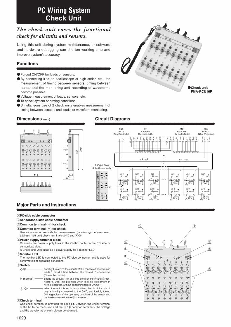
1023
Dimensions (mm)
116 22.5(41)
130 ( 149)
2 4 6
8 10 12 14
1 3 5 7
9 11 13 15
0
OFF OFF OFF OFF OFF OFF OFF OFF
OFF OFF OFF OFF OFF OFF OFF OFF
N N N N N N N
N N N N N N N
e
q w
r
t
i
t
y
u
Circuit Diagrams
2 4 6 8 10 12 14 16 18 201 3 5 7 9 11 13 15 17 19
+�-�
L7 LELF L6 LD L5 LC L4 LB L3 LA L2 L9 L1 L8 L0 R7 RERF R6 RD R5 RCR4 RB R3 RA R2 R9 R1 R8 R0
TP+ TP+ TP- TP-
LED 0
L0 R0
TP 0SW 0
LED 8
L8 R8
TP 8SW 8
LED 1
L1 R1
TP 1SW 1
LED 9
L9 R9
TP 9SW 9
LED 2
L2 R2
TP 2SW 2
LED 10
LA RA
TP 10SW 10
LED 5
L5 R5
TP 5SW 5
LED 13
LD RD
TP 13SW 13
LED 6
L6 R6
TP 6SW 6
LED 14
LE RE
TP 14SW 14
LED 7
L7 R7
TP 7SW 7
LED 15
LF RF
TP 15SW 15
2 4 6 8 10 12 14 16 18 201 3 5 7 9 11 13 15 17 19
+�-�
CN3LPA1/2
[Nihon Weidmuller]
CN1FL20A2MA
[Oki Electric Cable]
CN4LPA1/2
[Nihon Weidmuller]
CN2FL20A2MA
[Oki Electric Cable]
Single pole triple throw switch
OF
F(O
N)
N (N
orm
al)
●Check unit●FMA-RCU16F
PC Wiring SystemCheck Unit
●Forced ON/OFF for loads or sensors.●By connecting it to an oscilloscope or high coder, etc., the
measurement of timing between sensors, timing betweenloads, and the monitoring and recording of waveformsbecome possible.
●Voltage measurement of loads, sensors, etc.●To check system operating conditions.●Simultaneous use of 2 check units enables measurement of
timing between sensors and loads, or waveform monitoring.
Functions
The check unit eases the functionalcheck for all units and sensors.
Using this unit during system maintenance, or softwareand hardware debugging can shorten working time andimprove system’s accuracy.
Major Parts and Instructions
qPC-side cable connectorwSensor/load-side cable connectoreCommon terminal (+) for checkrCommon terminal (-) for check
Use as common terminals for measurement (monitoring) between eachaddress (1bit unit) check terminals i-e and i-r.
tPower supply terminal blockConnects the power supply lines in the Okiflex cable on the PC side orsensor/load side.※Check unit: Also used as a power supply for a monitor LED.
yMonitor LEDThe monitor LED is connected to the PC-side connector, and is used forconfirmation of operating conditions.
uSwitch
iCheck terminalOne check terminal is provided for each bit. Between the check terminalof the bit to be measured and the e /r common terminals, the voltageand the waveforms of each bit can be obtained.
Forcibly turns OFF the circuits of the connected sensors andloads 1 bit at a time between the q and w connectors(Opens the circuits).Shorts the circuits 1 bit at a time between the q and w con-nectors. Use this position when leaving equipment in normal operation without performing forced ON/OFF.When the switch is set in this position, the circuit for this bitonly is forcibly connected to the GND, and forcibly turnedON, regardless of the operating condition of the sensor andthe load connected to the w connector.
OFF
N (normal)
(ON)
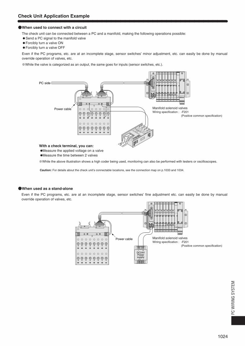
1024
PC W
IRIN
G SY
STEM
●When used to connect with a circuit
The check unit can be connected between a PC and a manifold, making the following operations possible:●Send a PC signal to the manifold valve●Forcibly turn a valve ON●Forcibly turn a valve OFF
Even if the PC programs, etc. are at an incomplete stage, sensor switches’ minor adjustment, etc. can easily be done by manualoverride operation of valves, etc.
※While the valve is categorized as an output, the same goes for inputs (sensor switches, etc.).
With a check terminal, you can:●Measure the applied voltage on a valve●Measure the time between 2 valves
※While the above illustration shows a high coder being used, monitoring can also be performed with testers or oscilloscopes.
A B A B A B A B A BA B A B
PC side
Power cable
A B A B A B A B A BA B A B
+�-�
Power cable
DC24VPowersupply
●When used as a stand-alone
Even if the PC programs, etc. are at an incomplete stage, sensor switches’ fine adjustment etc. can easily be done by manualoverride operation of valves, etc.
Check Unit Application Example
Manifold solenoid valvesWiring specification : -F201
(Positive common specification)
Caution: For details about the check unit’s connectable locations, see the connection map on p.1033 and 1034.
Manifold solenoid valvesWiring specification : -F201
(Positive common specification)

1025
OMRON
Mitsubishi Electric
Fuji Electric FAComponent & Systems
TOSHIBA
YASKAWA ELECTRIC
SHARP
YOKOGAWA ELECTRIC
KOYO ELECTRONIC INDUSTRIES
Hitachi
Matsushita Electric Works
KEYENCE
●Branch unit
Compatible types
OMRONDirect connecting type
Mitsubishi ElectricDirect connecting type
Input
Output
Input
Output
Input
Output
Input
Output
Input
Output
Input
Output
Input
Output
Input
Output
Input
Output
Input
Output
Input
Output
Input
Output
Input
Output
C200H-ID216, C500-ID219, C200H-ID217
C200H-OD218, C500-OD213, C200H-OD219
A1SX41, AX42, A1SX42Note
A1SY41, AY42, A1SY42Note
C200H-ID216, CQM1-ID213, C500-ID219, C200H-ID217
C200H-OD218, CQM1-OD213, C500-OD213, C200H-OD219
A1SX41, AJ35TC1-32D, AX42, A1SX42
A1SY41, AJ35TC1-32T, AY42, A1SY42
FTU125A, NS-X64-I, NV1X3204(-W), NV1X3206
NC1X3204, NC1X3206, NC1X6404, NC1X6406
FTU222A, NS-Y64-TI, NV1Y32T05P1
NC1Y32T05P1, NC1Y64T05P1-1
DI335, DI-6241
DO335, DO-6242
JAMSC-B2605
JAMSC-B2604
JW-34NC, JW-234N, JW-64NC, JW-264N
JW-32SC, JW-232S, JW-62SC, JW-262S
F3XD32-3N, F3XD64-3N
F3YD32-1A, F3YD64-1A
U-09N
U-19T
XDC24D2H
YTR24DH
AFP23067, AFP33027, AFP33028, AFP33068
AFP23407, AFP33487
KZ-C32X
KZ-C32T
Order code
FCN connector type MIL connector type
FMA-TF3120-OR
FMA-TF3020-OR
FMA-TF3120-MBA
FMA-TF3120-MBB
FMA-TF3020-MBA
FMA-TF3020-MBB
FMA-TF4120-OR FMA-TE4120-OR
FMA-TF4020-OR FMA-TE4020-OR
FMA-TF4120-MB FMA-TE4120-MB
FMA-TF4020-MB FMA-TE4020-MB
FMA-TF4120-FJ FMA-TE4120-FJ
FMA-TF4020-FJ FMA-TE4020-FJ
FMA-TF4120-TB FMA-TE4120-TB
FMA-TF4020-TB FMA-TE4020-TB
FMA-TF4120-YS FMA-TE4120-YS
FMA-TF4020-YS FMA-TE4020-YS
FMA-TF4120-SP FMA-TE4120-SP
FMA-TF4020-SP FMA-TE4020-SP
FMA-TF4120-YG FMA-TE4120-YG
FMA-TF4020-YG FMA-TE4020-YG
FMA-TF4120-KD FMA-TE4120-KD
FMA-TF4020-KD FMA-TE4020-KD
FMA-TE4120-HT
FMA-TE4020-HT
FMA-TE4120-MS
FMA-TE4020-MS
FMA-TE4120-KY
FMA-TE4020-KY
Package unit
1
1
1
1
1
1
1
1
1
1
1
1
1
1
1
1
1
1
1
1
1
1
1
1
1
1
Remark: The metal box to store the unit is also available as a special.
OMRON
Mitsubishi Electric
Fuji Electric FAComponent & Systems
TOSHIBA
YASKAWA ELECTRIC
SHARP
YOKOGAWA ELECTRIC
KOYO ELECTRONIC INDUSTRIES
Hitachi
Matsushita Electric Works
KEYENCE
●32-input and output unit
Compatible types
Input
Output
Input
Output
Input
Output
Input
Output
Input
Output
Input
Output
Input
Output
Input
Output
Input
Output
Input
Output
Input
Output
C200H-ID216, CQM1-ID213, C500-ID219, C200H-ID217
C200H-OD218, CQM1-OD213, C500-OD213, C200H-OD219
A1SX41, AJ35TC1-32D, AX42, A1SX42
A1SY41, AJ35TC1-32T, AY42, A1SY42
FTU125A, NS-X64-I, NV1X3204(-W), NV1X3206
NC1X3204, NC1X3206, NC1X6404, NC1X6406
FTU222A, NS-Y64-TI, NV1Y32T05P1
NC1Y32T05P1, NC1Y64T05P1-1
DI335, DI-6241
DO335, DO-6242
JAMSC-B2605
JAMSC-B2604
JW-34NC, JW-234N, JW-64NC, JW-264N
JW-32SC, JW-232S, JW-62SC, JW-262S
F3XD32-3N, F3XD64-3N
F3YD32-1A, F3YD64-1A
U-09N
U-19T
XDC24D2H
YTR24DH
AFP23067, AFP33027, AFP33028, AFP33068
AFP23407, AFP33487
KZ-C32X
KZ-C32T
Order code
FCN connector type MIL connector type
FMA-TM1132-OR FMA-TL1132-OR
FMA-TM1032-OR FMA-TL1032-OR
FMA-TM1132-MB FMA-TL1132-MB
FMA-TM1032-MB FMA-TL1032-MB
FMA-TM1132-FJ FMA-TL1132-FJ
FMA-TM1032-FJ FMA-TL1032-FJ
FMA-TM1132-TB FMA-TL1132-TB
FMA-TM1032-TB FMA-TL1032-TB
FMA-TM1132-YS FMA-TL1132-YS
FMA-TM1032-YS FMA-TL1032-YS
FMA-TM1132-SP FMA-TL1132-SP
FMA-TM1032-SP FMA-TL1032-SP
FMA-TM1132-YG FMA-TL1132-YG
FMA-TM1032-YG FMA-TL1032-YG
FMA-TM1132-KD FMA-TL1132-KD
FMA-TM1032-KD FMA-TL1032-KD
FMA-TL1132-HT
FMA-TL1032-HT
FMA-TL1132-MS
FMA-TL1032-MS
FMA-TL1132-KY
FMA-TL1032-KY
Package unit
1
1
1
1
1
1
1
1
1
1
1
1
1
1
1
1
1
1
1
1
1
1
Order Codes
Note: When using A1SX42 and A1SY42, always use in combination with FMA-TF3120-MBA and FMA-TF3120-MBB, or FMA-TF3020-MBA and FMA-TF3020-MBB.Remark: The metal box to store the unit is also available as a special.

1026
PC W
IRIN
G SY
STEM
●8-, 16-input and output unit
I/O numbers/Specifications
8-input/DIN rail mounting type
16-input/DIN rail mounting type
8-input/Box-mounting type
16-input/Box-mounting type
8-output/DIN rail mounting type
16-output/DIN rail mounting type
8-output/Box-mounting type
16-output/Box-mounting type
Order code
FMA-TM1108
FMA-TM1116
FMA-TM2108
FMA-TM2116
FMA-TM1008
FMA-TM1016
FMA-TM2008
FMA-TM2016
Package unit
1
1
1
1
1
1
1
1
●8 LO/HI-only input and output unit
I/O numbers/Specifications
8 LO-only inputs/DIN rail mounting type
8 HI-only inputs/DIN rail mounting type
8 LO-only inputs/Box-mounting type
8 HI-only inputs/Box-mounting type
8 LO-only outputs/DIN rail mounting type
8 HI-only outputs/DIN rail mounting type
8 LO-only outputs/Box-mounting type
8 HI-only outputs/Box-mounting type
Order code
FMA-TJ1108
FMA-TK1108
FMA-TJ2108
FMA-TK2108
FMA-TJ1008
FMA-TK1008
FMA-TJ2008
FMA-TK2008
Package unit
1
1
1
1
1
1
1
1
●16-output common reduction unit
Number of outputs/Specifications
16-output/DIN rail mounting type
Order code
FMA-TH1016
Package unit
1
●Connector type 8-, 16-input and output unit
I/O numbers/Specifications
8-input (main)/DIN rail mounting type
8-input (sub-unit)/DIN rail mounting type
16-input/DIN rail mounting type
8-output (main)/DIN rail mounting type
8-output (sub-unit)/DIN rail mounting type
16-output/DIN rail mounting type
Order code
FMA-TC1108
FMA-TD1108
FMA-TC1116
FAM-TC1008
FMA-TD1008
FMA-TC1016
Package unit
1
1
1
1
1
1
●Unit for Mitsubishi Electric FX2, FX2C series only(For FX2-32MT-C, FX2-64MT-C, FX2C-64MT, FX2C-96MT, FX2C-128MT, FX2C-160MT)
I/O numbers/Specifications
8-input/DIN rail mounting type
16-input/DIN rail mounting type
8-input/Box-mounting type
16-input/Box-mounting type
8-output/DIN rail mounting type
16-output/DIN rail mounting type
8-output/Box-mounting type
16-output/Box-mounting type
Order code
FMA-TM1108-MB
FMA-TM1116-MB
FMA-TM2108-MB
FMA-TM2116-MB
FMA-TM1008-MB
FMA-TM1016-MB
FMA-TM2008-MB
FMA-TM2016-MB
Package unit
1
1
1
1
1
1
1
1
●Connectors
Parts Order code Package unit Remarks
20 pins half pitch connector FMA-BF20HA 1 IDEC Izumi JM1S-0203
20 pins flat cable connector FMA-BF20KA 10 Oki Electric Cable FL20A2FO
34 pins flat cable connector FMA-BF34KA 1 Oki Electric Cable FL34A2FO
40 pins flat cable connector FMA-BF40KA 1 Oki Electric Cable FL40A2FO
24 pins 360 type connector FMA-BF24JA 1 Fujitsu FCN-367J024
40 pins 360 type connector FMA-BF40JA 1 Fujitsu FCN-367J040
3 pins MolexFMA-BM03A
10 Housing: 51103-0300
connector set 30 Terminal: 50351-8100
●Check unit, connecting cable, and crimping tool
Parts
Check unit
Connecting cableNote
Crimping tool
Order code (package unit)
FMA-RCU16F (1 unit)
FMA-CX10×10 (10m [32.8ft.]), FMA-CX10×100 (100m [328ft.])
FMA-CX20×20 (20m [65.6ft.]), FMA-CX20×100 (100m [328ft.])
FMA-CX40×20 (20m [65.6ft.]), FMA-CX40×100 (100m [328ft.])
FMA-CY20×20 (20m [65.6ft.]), FMA-CY20×100 (100m [328ft.])
FMA-CY40×20 (20m [65.6ft.]), FMA-CY40×100 (100m [328ft.])
FMA-HT151 (1 set)
Remarks
Flat cable with insulation containing power cable
Flat cable with insulation containing power cable
Flat cable with insulation containing power cable
Flat cable with insulation containing power cable
Flat cable with insulation containing power cable
Crimping tool for flat cable
Note: Production of oil-resistant specifications, and deliveries in cable lengths other than package unit lengths, are also possible. Consult us.
Okiflex
Okiflex with shield
10 leads
20 leads
40 leads
20 leads
40 leads
OMRON
Mitsubishi Electric
Fuji Electric FAComponents & Systems
TOSHIBA
YASKAWA ELECTRIC
SHARP
YOKOGAWA ELECTRIC
KOYO ELECTRONIC INDUSTRIES
Hitachi
Matsushita Electric Works
KEYENCE
●32-output common reduction unit
Compatible models
Output
C200H-OD218, CQM1-OD213, C500-OD213, C200H-OD219
A1SY41, AJ35TC1-32T, AY42, A1SY42
FTU222A, NS-Y64-TI, NV1Y32T05P1, NC1Y32T05P1, NC1Y64T05P1-1
DO335, DO-6242
JAMSC-B2604
JW-32SC, JW-232S, JW-62SC, JW-262S
F3YD32-1A, F3YD64-1A
U-19T
YTR24DH
AFP23407, AFP33487
KZ-C32T
Order code
FCN connector type MIL connector type
FMA-TH1032-OR FMA-TG1032-OR
FMA-TH1032-MB FMA-TG1032-MB
FMA-TH1032-FJ FMA-TG1032-FJ
FMA-TH1032-TB FMA-TG1032-TB
FMA-TH1032-YS FMA-TG1032-YS
FMA-TH1032-SP FMA-TG1032-SP
FMA-TH1032-YG FMA-TG1032-YG
FMA-TH1032-KD FMA-TG1032-KD
FMA-TG1032-HT
FMA-TG1032-MS
FMA-TG1032-KY
Package unit
1
1
1
1
1
1
1
1
1
1
1

Applicable tools and parts for use when wiring PC Wiring System are available in other companies, see the table below:
1027
Order code
SD-3H1×75
SD
FUE2
BT1.25-9-1
HTN21
H0.25/12
H0.34/12
H0.5/12
H0.75/12
H1/12
PZ1.5
PZ4
RC80
Applicable Tools and Parts
Parts
Phillips’ screw driver
Flatblade screw driver
Heat-shrink tube
Crimp-style terminal (bar terminal)
Crimper for crimp-style terminal
Crimp-style sleeve
Crimper for crimp-style sleeve
Cutter for flat cable
Package unit
1
1
1m [3.3ft.], 50m [164ft.]
1m [3.3ft.], 50m [164ft.]
1m [3.3ft.], 50m [164ft.]
1000
1
500
500
500
500
500
1
1
1
Remarks
Made by Nihon Weidmuller
Made by Nihon Weidmuller
Made by Fujikura (for Okiflex 10 leads )
Made by Fujikura (for Okiflex 10, 20 leads)
Made by Fujikura (for Okiflex 20, 40 leads)
Made by Nichifu for 0.25~1.65mm2 [0.00039~0.00256in.2]
Made by Nihon Weidmuller
Made by Nihon Weidmuller for 0.25mm2 [0.00039in.2] twisted wire (AWG24)
Made by Nihon Weidmuller for 0.34mm2 [0.00053in.2] twisted wire (AWG22)
Made by Nihon Weidmuller for 0.5mm2 [0.00078in.2] twisted wire (AWG20)
Made by Nihon Weidmuller for 0.75mm2 [0.00116in.2] twisted wire (AWG18)
Made by Nihon Weidmuller for 1.0mm2 [0.00155in.2] twisted wire (AWG17)
Made by Nihon Weidmuller (for 0.25mm2~1.5mm2 [0.00039~0.00233in.2])
Made by Nihon Weidmuller (for 0.5mm2~4mm2 [0.00078~0.00620in.2])
Made by Nihon Weidmuller
Productnumber
994519
903700
―
―
―
―
901471
902576
902577
040950
040960
040970
900599
901250
901704
(Nominal size 10mm [0.39in.])
(Nominal size 13mm [0.51in.])
(Nominal size 16mm [0.63in.])
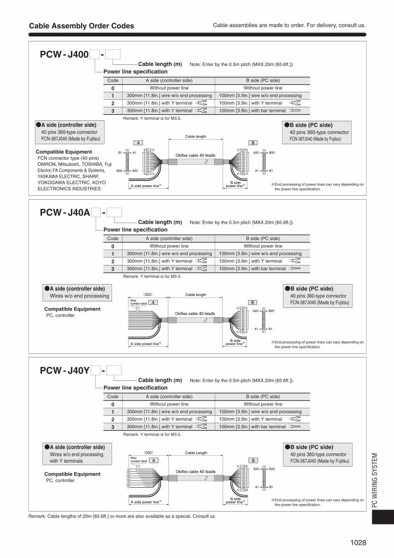
1028
PC W
IRIN
G SY
STEM
PCW - J400 1 -
PCW - J40A 1 -
PCW - J40Y 1 -
Code A side (controller side) B side (PC side)
0 Without power line Without power line
1 300mm [11.8in.] wire w/o end processing 100mm [3.9in.] wire w/o end processing
2 300mm [11.8in.] with Y terminal 100mm [3.9in.] with Y terminal
3 300mm [11.8in.] with Y terminal 100mm [3.9in.] with bar terminal
Remark: Y terminal is for M3.5.
Cable length (m) Note: Enter by the 0.5m pitch (MAX.20m [65.6ft.]).
Power line specification
Cable Assembly Order Codes
B20A20
B1A1B20 A20
B1 A1
A B
Cable length
Okiflex cable 40 leads
A side power line※�B side
power line※�
Code A side (controller side) B side (PC side)
0 Without power line Without power line
1 300mm [11.8in.] wire w/o end processing 100mm [3.9in.] wire w/o end processing
2 300mm [11.8in.] with Y terminal 100mm [3.9in.] with Y terminal
3 300mm [11.8in.] with Y terminal 100mm [3.9in.] with bar terminal
Remark: Y terminal is for M3.5.
Cable length (m) Note: Enter by the 0.5m pitch (MAX.20m [65.6ft.]).
Power line specification
B20A20
B1A1
BAWire number label
Cable length
Okiflex cable 40 leads
B sidepower line※�A side power line※�
(300)�
Code A side (controller side) B side (PC side)
0 Without power line Without power line
1 300mm [11.8in.] wire w/o end processing 100mm [3.9in.] wire w/o end processing
2 300mm [11.8in.] with Y terminal 100mm [3.9in.] with Y terminal
3 300mm [11.8in.] with Y terminal 100mm [3.9in.] with bar terminal
Remark: Y terminal is for M3.5.
Cable length (m) Note: Enter by the 0.5m pitch (MAX.20m [65.6ft.]).
Power line specification
B20A20
B1A1
A BWire number label
(300)� Cable Length
Okiflex cable 40 leads
B sidepower line※�A side power line※�
Remark: Cable lengths of 20m [65.6ft.] or more are also available as a special. Consult us.
Cable assemblies are made to order. For delivery, consult us.
●A side (controller side)40 pins 360-type connector FCN-367J040 (Made by Fujitsu)
Compatible EquipmentFCN connector type (40 pins)OMRON, Mitsubishi, TOSHIBA, FujiElectric FA Components & Systems,YASKAWA ELECTRIC, SHARP,YOKOGAWA ELECTRIC, KOYOELECTRONICS INDUSTRIES
●B side (PC side)40 pins 360-type connectorFCN-367J040 (Made by Fujitsu)
※End processing of power lines can vary depending onthe power line specification.
※End processing of power lines can vary depending onthe power line specification.
※End processing of power lines can vary depending onthe power line specification.
●A side (controller side)Wires w/o end processing
Compatible EquipmentPC, controller
●B side (PC side)40 pins 360-type connector FCN-367J040 (Made by Fujitsu)
●A side (controller side)Wires w/o end processing, with Y terminals
Compatible EquipmentPC, controller
●B side (PC side)40 pins 360-type connector FCN-367J040 (Made by Fujitsu)

1029
PCW - F40A 1 -
PCW - F40Y 1 -
PCW - F400 1 -
Code A side (controller side) B side (PC side)
0 Without power line Without power line
1 300mm [11.8in.] wire w/o end processing 100mm [3.9in.] wire w/o end processing
2 300mm [11.8in.] with Y terminal 100mm [3.9in.] with Y terminal
3 300mm [11.8in.] with Y terminal 100mm [3.9in.] with bar terminal
Remark: Y terminal is for M3.5.
Cable length (m) Note: Enter by the 0.5m pitch (MAX.20m [65.6ft.]).
Power line specification
2
4039
3940
2
A B
Cable length
Okiflex cable 40 leads
1(▲ mark)�
A side power line※�
1(▲ mark)�
B sidepower line※�
3940
2
BAWire number label
(300)� Cable length
Okiflex cable 40 leads
1(▲ mark)�
B sidepower line※�A side power line※�
3940
2A BWire
number label
(300)� Cable length
Okiflex cable 40 leads
1(▲ mark)�
B sidepower line※�A side power line※�
Remark: Cable lengths of 20m [65.6ft.] or more are also available as a special. Consult us.
Cable Assembly Order Codes Cable assemblies are made to order. For delivery, consult us.
●A side (controller side)40 pins flat cable connectorFL40A2FO (Made by Oki Electric Cable) or equivalent
Compatible EquipmentMIL connector type (40 pins)Hitachi, Matsushita Electric Works
●B side (PC side)40 pins flat cable connector FL40A2FO (Made by Oki ElectricCable) or equivalent
※End processing of power lines can vary depending onthe power line specification.
※End processing of power lines can vary depending onthe power line specification.
※End processing of power lines can vary depending onthe power line specification.
●A side (controller side)Wires w/o end processing
Compatible EquipmentPC, controller
●B side (PC side)40 pins flat cable connector FL40A2FO (Made by Oki ElectricCable) or equivalent
●A side (controller side)Wires w/o end processing, with Y terminals
Compatible EquipmentPC, controller
●B side (PC side)40 pins flat cable connector FL40A2FO (Made by Oki ElectricCable) or equivalent

1030
PC W
IRIN
G SY
STEM
PCW- H200 1 -Power line specification
Cable length (m) Note: Enter by the 0.5m pitch (MAX.20m [65.6ft.]).
PCW- F200 1 -
Code A side (controller side) B side (PC side)
0 Without power line Without power line
1 300mm [11.8in.] wire w/o end processing 100mm [3.9in.] wire w/o end processing
2 300mm [11.8in.] with Y terminal 100mm [3.9in.] with Y terminal (Relay terminal, others)
3 300mm [11.8in.] with Y terminal 100mm [3.9in.] with bar terminal (For 8-, 16-signal input/output units)Note
4 300mm [11.8in.] with Y terminal 100mm [3.9in.] with round terminal (For Koganei F201 specification manifold)
5 100mm [3.9in.] with bar terminal 100mm [3.9in.] with Y terminal (Relay terminal, others)
6 100mm [3.9in.] with bar terminal 100mm [3.9in.] with bar terminal (For 8-, 16-signal input/output units)Note
7 100mm [3.9in.] with bar terminal 100mm [3.9in.] with round terminal (For Koganei F201 specification manifold)
Remark: Y terminal is for M3.5, round terminal is for M3.
Power line specification
Code A side (controller side) B side (PC side)
0 Without power line Without power line
1 300mm [11.8in.] wire w/o end processing 100mm [3.9in.] wire w/o end processing
2 300mm [11.8in.] with Y terminal 100mm [3.9in.] with Y terminal (Relay terminal, others)
3 300mm [11.8in.] with Y terminal 100mm [3.9in.] with bar terminal (For 8-, 16-signal input/output units)Note
4 300mm [11.8in.] with Y terminal 100mm [3.9in.] with round terminal (For Koganei F201 specification manifold)
5 100mm [3.9in.] with bar terminal 100mm [3.9in.] with Y terminal (Relay terminal, others)
6 100mm [3.9in.] with bar terminal 100mm [3.9in.] with bar terminal (For 8-, 16-signal input/output units)Note
7 100mm [3.9in.] with bar terminal 100mm [3.9in.] with round terminal (For Koganei F201 specification manifold)
Remark: Y terminal is for M3.5, round terminal is for M3.
Cable length (m) Note: Enter by the 0.5m pitch (MAX.20m [65.6ft.]).
1020
112
20 19
A B
1(▲ mark)�
A sidepower line※�
Cable length
Okiflex cable 20 leads 1(▲ mark)�
B sidepower line※�
2
20 19
2
20 19
A B
1(▲ Mark)�
Cable length
Okiflex cable 20 leads 1(▲ Mark)�
B sidepower line※�
A sidepower line※�
Remark: Cable lengths of 20m [65.6ft.] or more are also available as a special. Consult us.
PCW- G400 1 -
Code A side (controller side) B side (PC side)
0 Without power line Without power line
1 300mm [11.8in.] wire w/o end processing 100mm [3.9in.] wire w/o end processing
2 300mm [11.8in.] with Y terminal 100mm [3.9in.] with Y terminal
3 300mm [11.8in.] with Y terminal 100mm [3.9in.] with bar terminal
Remark: Y terminal is for M3.5.
Cable length (m) Note: Enter by the 0.5m pitch (MAX.20m [65.6ft.]).
Power line specification
B20 A20
B1 A1
3940
2
A B
Cable length
Okiflex cable 40 leads
1(▲ mark)�
B sidepower line※�A side power line※�
AConnector No.A1B1A2B2A3B3A4B4A5B5A6B6A7B7A8B8A9B9A10B10A11B11A12B12A13B13A14B14A15B15A16B16A17B17A18B18A19B19A20B20
B Connector No.12345678910111213141516171819202122232425262728293031323334353637383940
Sheathed wiring table
Cable Assembly Order Codes Cable assemblies are made to order. For delivery, consult us.
●A side (controller side)40 pins 360-type connector FCN-367J040 (Made by Fujitsu)
Compatible EquipmentFCN connector type (40 pins)OMRON, Mitsubishi, TOSHIBAFuji Electric FA Components &Systems, YASKAWA ELECTRIC,SHARP, YOKOGAWA ELECTRIC,KOYO ELECTRONICSINDUSTRIES
※End processing of power lines can varydepending on the power line specification.
Caution: This is for the types that the Aand B connector numbers aremismatched. See the diagramon the right.
●B side (PC side)40 pins flat cable connectorFL40A2FO (Made by Oki ElectricCable) or equivalent
●A side (controller side)20 pins half pitch connectorJM1S-0203 (Made by IDEC Izumi)
Compatible EquipmentBranch unitDirect connecting type
※End processing of power lines can vary depending on thepower line specification.
Note: Can also handle connector type 8- and 16-input/output units.
●B side (PC side)20 pins flat cable connector FL20A2FO (Made by Oki ElectricCable) or equivalent
●A side (controller side)20 pins flat cable connector FL20A2FO (Made by Oki Electric Cable) or equivalent
Compatible EquipmentRelay terminalBranch unit (Cannot select power line with Y terminal)8-, 16-input/output unitNote
(Cannot select power line with Y terminal)
※End processing of power lines can vary depending on thepower line specification.
Note: Can also handle connector type 8- and 16-input/output units.
●B side (PC side)20 pins flat cable connector FL20A2FO (Made by Oki ElectricCable) or equivalent

1031
PCW - F34A 1 -
PCW - F34Y 1 -
PCW - F340 1 -
Code A side (controller side) B side (PC side)
0 Without power line Without power line
1 300mm [11.8in.] wire w/o end processing 100mm [3.9in.] wire w/o end processing
2 300mm [11.8in.] with Y terminal 100mm [3.9in.] with Y terminal
3 300mm [11.8in.] with Y terminal 100mm [3.9in.] with bar terminal
Remark: Y terminal is for M3.5.
Cable length (m) Note: Enter by the 0.5m pitch (MAX.20m [65.6ft.]).
Power line specification
2
3433
3334
2
A B
1(▲ mark)�
A side power line※�
Cable length
Okiflex cable 40 leads1(▲ mark)�
B sidepower line※�
3334
2
BA
(300)�Wire number label
A side power line※�
Cable length
Okiflex cable 40 leads1(▲ mark)�
B sidepower line※�
3334
2
BA
(300)�
Wire number label
A side power line※�B side
power line※�
1(▲ mark)�
Cable length
Okiflex cable 40 leads
Remark: Cable lengths of 20m [65.6ft.] or more are also available as a special. Consult us.
Cable Assembly Order Codes Cable assemblies are made to order. For delivery, consult us.
●A side (controller side)34 pins flat cable connector FL34A2FO (Made by Oki ElectricCable) or equivalent
Compatible EquipmentMIL connector type (34 pins)KEYENCE
●B side (PC side)34 pins flat cable connector FL34A2FO (Made by Oki ElectricCable) or equivalent
※End processing of power lines can vary depending onthe power line specification.
※End processing of power lines can vary depending onthe power line specification.
※End processing of power lines can vary depending onthe power line specification.
●A side (controller side)Wires w/o end processing
Compatible EquipmentPC, controller
●B side (PC side)34 pins flat cable connector FL34A2FO (Made by Oki ElectricCable) or equivalent
●A side (controller side)Wires w/o end processing, with Y terminals
Compatible EquipmentPC, controller
●B side (PC side)34 pins flat cable connector FL34A2FO (Made by Oki ElectricCable) or equivalent

1032
PC W
IRIN
G SY
STEM
PCW - J240 1 -
Code A side (controller side) B side (PC side)
0 Without power line Without power line
1 300mm [11.8in.] wire w/o end processing 100mm [3.9in.] wire w/o end processing
2 300mm [11.8in.] with Y terminal 100mm [3.9in.] with Y terminal (Relay terminal, others)
3 300mm [11.8in.] with Y terminal 100mm [3.9in.] with bar terminal (For 8-, 16-input/output units)Note
4 300mm [11.8in.] with Y terminal 100mm [3.9in.] with round terminal (For Koganei F201 specification manifold)
Remark: Y terminal is for M3.5, round terminal is for M3.
Cable length (m) Note: Enter by the 0.5m pitch (MAX.20m [65.6ft.]).
Power line specification
A12B12
B1 A12
20 19
A B
A side power line※�
Cable length
Okiflex cable 20 leads 1(▲ mark)�
B sidepower line※�
AConnector No.A1B1A2B2A3B3A4B4A5B5A6B6A7B7A8B8A9B9A10B10A11B11A12B12
BConnector No.2019181716151413121110987654321
Sheathed wiring table
1
2
3
4
5
6
7
8
9
10
11
12
20
1
2
3
4
5
6
7
8
9
10
11
12
1
2
3
4
5
6
7
8
9
10
11
12
13
14
15
16
17
18
19
・・・・・・�
・・・・・・�
Wiring diagram PC sideConnector pin No. A B column column
PC side Unit side
▲ mark
●For connecting OMRON’s C500-ID218CN, C200H-ID215, C500-OD415CN, C200H-OD215, C500-MD211CN, or C200H-MD215 with 8- or 16-input/outputunits, manufacture and use the cable assemblies shown in the diagram below:
Cable Assembly Order Codes Cable assemblies are made to order. For delivery, consult us.
Caution:The A and B sideconnector numbersare mismatched. Seethe diagram below.
●A side (controller side)24 pins 360-type connector FCN-367J024 (Made by Fujitsu)
Compatible EquipmentFCN connector type (24 pins)OMRON
※End processing of power lines can varydepending on the power line specification.
Note: Can also handle connector types 8- and16-input/output units.
●B side (PC side)20 pins flatCable connector FL20A2FO (Made by Oki ElectricCable) or equivalent
PC-side connector
PC-side applicable connector
Unit-side connector
Unit-side applicable connector
Made by Fujitsu
Made by Fujitsu
Made by Oki Electric Cable
Made by Oki Electric Cable
FCN-365P024
FCN-367J024
FL20A2MS
FL20A2FO (equivalent)
Remark: Although the method of pin No. identification varies, a cable assembly with connectors already crimped is available. The model is PCW-J240□-□.(See diagram above)
Note: The connector pin numbers areassigned for convenience. Use the ▲mark as the reference.

1033
PC Wiring System Connection Map
●For models other than those listed above, consult us.
24P 24P
32-I/O(16-I/O×2)�
PC�multi-signal I/O unit
64-I/O(32-I/O×2)�
PC�multi-signal I/O unit
32-I/O(32-I/O×1)�
32-I/O×1
Serial remoteconnector I/O unit
Mitsubishi Electric� FX2-32MT-C� FX2-64MT-C� FX2C-64MT� FX2C-96MT� FX2C-128MT� FX2C-160MT
40P
40P
40P
40P(34P)�
(16-I/O×2)×n�
With I/O connector micro sequencer
Note: The branch unit (direct connecting type) is not applicable.
Note: The branch unit (direct connecting type) is not applicable.
OMRON Input : C500-ID218CN, C200H-ID215 Output : C500-OD415CN, C200H-OD215 Combination : C500-MD211CN, C200H-MD215 Note : When connecting the above input/ output cards, please refer to p.1032.
OMRON Input : C500-ID219, C200H-ID217, C200H-ID216,CQM1-ID213 Output : C500-OD213, C200H-OD219, C200H-OD218, CQM1-OD213Mitsubishi Electric Input : AX42, A1SX42, A1SX41 Output : AY42, A1SY42, A1SY41Fuji Electric FA Components & Systems. Input : FTU125A, NS-X64-I, NV1X3204 (-W), NV1X3206 NC1X3204, NC1X3206, NC1X6404, NC1X6406 Output : FTU222A, NS-Y64-TI, NV1Y32T05P1 出力 : NC1Y32T05P1, NC1Y64T05P1-1TOSHIBA Input : DI335, DI-6241 Output : DO335, DO-6242YASKAWA ELECTRIC Input : JAMSC-B2605 Output : JAMSC-B2604SHARP Input : JW-64NC, JW-34NC, JW-234N, JW-264N Output : JW-62SC, JW-32SC, JW-232S, JW-262SYOKOGAWA ELECTRIC Input : F3XD64-3N, F3XD32-3N Output : F3YD64-1A, F3YD32-1AKOYO ELECTRONICS INDUSTRIES Input : U-09N Output : U-19T
Matsushita Electric Works Input : AFP23067, AFP33027, AFP33028, AFP33068 Output : AFP23407, AFP33487Hitachi Input : XDC24D2H Output : YTR24DHKEYENCE Input : KZ-C32X Output : KZ-C32T
Note
Note
Mitsubishi Electric� Input : AJ35TC1-32D Output : AJ35TC1-32T
Note
Note
Manifold solenoid valveA B A B A B A B A BA B A B
●F series solenoid valves Wiring specifications : -F201 type (Positive common specification)●FM Solid Manifold X80M, X88M series Wiring module : FMCR-F201, FMC-F201 type (Positive common
specification)
Branch unit 32-I/O →16-I/O ×2
Branch unit(Direct connecting type)
For input : FMA-TF4120-□For output : FMA-TF4020-□
Cable AssemblyPCW-F200□
Cable AssemblyPCW-J240□
Cable AssemblyPCW-F200□
Cable AssemblyPCW-H200□
Direct connecting type For OMRON and
Mitsubishi Electric only
For input : FMA-TF3120-□For output : FMA-TF3020-□
For input : FMA-TE4120-□For output : FMA-TE4020-□
Cable AssemblyPCW-J400□
Cable AssemblyPCW-G400□PCW-F400□PCW-F340□
Cable AssemblyPCW-G400□PCW-F400□PCW-F340□
Caution: Input/output unit for FX2,FX2C series is aspecialized unit

1034
PC W
IRIN
G SY
STEM
1 2 3 4 5 6 7 8
1
3
5
7
2
4
6
8
PC-VALVE UNIT
SNDPWR
8-input/output Unit
For input : FMA-TM1108For output : FMA-TM1008For input : FMA-TK1108For output : FMA-TK1008
For input : FMA-TM2108For output : FMA-TM2008For input : FMA-TK2108For output : FMA-TK2008
※Cascade connection (2 units) possible
8-input/output Unit(Box-mounting type)
Cable AssemblyPCW-F200□
※Cascade connection (2 units) possible
Cable AssemblyPCW-F200□
For input : FMA-TM1108For output : FMA-TM1008For input : FMA-TJ1108For output : FMA-TJ1008
For input : FMA-TM2108For output : FMA-TM2008For input : FMA-TJ2108For output : FMA-TJ2008
16-input/output Unit
For input : FMA-TM1116For output : FMA-TM1016※Unable to increase units.
For input : FMA-TM2116For output : FMA-TM2016
16-input/output Unit(Box-mounting type)
8-input/output Unit
8-input/output Unit(Box-mounting type)
PC-VALVE UNIT(8 outputs)PCV201□
2 0 P 2 0 P
OMRONG7 0 0 -
20P
FMA-TF2010
10P 10P20P
Serial transmission sub-stationOMRON
SYSMAC BUS/2 G700-EOD32(Output 16×2) G700-EID32(Input 16×2) G700-EMD32(Output 16×1, Input 16×1)SYSBUS G71-OD16(Output 16×1) G71-IC16(Input 16×1)
FMA-TF2010※Refer to PC-VALVE UNIT(p.790).
(FMA-AF101-F-###)
Cable AssemblyPCW-J400□
Wiring branch unit(16 outputs → 8 outputs×2)
32-input/output Unit
For input : FMA-TM1132-□For output : FMA-TM1032-□
For input : FMA-TL1132-□For output : FMA-TL1032-□
Check Unit
FMA-RCU16F
※ : Marks where the check units can be connected.

1035
Connection Example between Branch Unit and Equipment
The following products can also be directly connected to the various companies’ programmable controllers to reduce wiring.
2 3 4 5 6 7 8 9 A B C D E F10AAA
D�P��N�E�R��C�O�N�E�C�T�O�R
・�
・�
2 3 4 5 6 7 8 9 A B C D E F10AAA
D�P��N�E�R��C�O�N�E�C�T�O�R
・�
・�
MotherboardM7E
Digital indicator unitM7F-*N***M7F-*D***
PC relay terminalRT1S-OD16-**V-SRT1S-OD08-**V-S
PC terminalRT1-OD16-**V-SRT1-OD08-**V-SRT1-OD04-**V-SRT1-OD02-**V-S
RT2 relay terminalRT2S-OD16RT2S-C-OD16RT2S-M-OD16RT2S-MC-OD16
I/O relay terminalG7TC-OC16G7TC-OC08I/O terminalP7TF-OS16P7TF-OS08
Relay terminalG7VC-OC16G7VC-OA16G7VC-OD16
I/O relay terminalGT7TC-ID16GT7TC-IA16I/O terminalP7TF-IS16
Optical fiber sensorO-line type
PC TerminalRT1-ID16-**V-SRT1-ID08-**V-SRT1-ID04-**V-SRT1-IA16-**V-SRT1-IA08-**V-SRT1-IA04-**V-S
PC relay terminalRT1S-ID16-**V-SRT1S-ID08-**V-S
Sensor main blockSL-BMW
RT2 relay terminalRT2S-ID16RT2S-C-ID16RT2S-M-ID16RT2S-MC-ID16
Relay terminal socketG7OA-ZOS16-3
Inpu
t side
Outp
ut si
de
Branch unit
Branch unit(Direct connecting type)
KEYENCE
OMRON
OMRON
Matsushita Electric Works
SUNX
Matsushita Electric Works