Wiring & Installation Manual - Orion Li-Ion Battery ... & Installation Manual (Document Revision...
57
Wiring & Installation Manual (Document Revision 4.1) The Orion BMS by Ewert Energy Systems is designed to manage and protect Lithium ion battery packs and is suitable for use in electric, plug-in hybrid and hybrid electric vehicles as well as stationary applications. This version of the wiring manual has been updated to include new features available on hardware revision D and E. Revision D includes improved robustness for the 12v power supply, boosted robustness of interfaces, 2 new outputs and adds non-volatile memory to eliminate the need for always on power. Revision E has all the features of Revision D and also improves the robustness of the cell tap inputs and prevents damage to the unit from common wiring errors.
Transcript of Wiring & Installation Manual - Orion Li-Ion Battery ... & Installation Manual (Document Revision...
Wiring & Installation Manual
(Document Revision 4.1)
The Orion BMS by Ewert Energy Systems is designed to manage and protect Lithium ion
battery packs and is suitable for use in electric, plug-in hybrid and hybrid electric vehicles as well as
stationary applications.
This version of the wiring manual has been updated to include new features available on
hardware revision D and E. Revision D includes improved robustness for the 12v power supply,
boosted robustness of interfaces, 2 new outputs and adds non-volatile memory to eliminate the need
for always on power. Revision E has all the features of Revision D and also improves the robustness of
the cell tap inputs and prevents damage to the unit from common wiring errors.
Orion BMS Wiring Manual
2
Table of Contents
SAFETY: READ THIS FIRST ................................................................................................................ 4
Determining which BMS to order ........................................................................................................ 7
Theory of Operation............................................................................................................................. 9
Mounting ............................................................................................................................................ 10
Physical Mounting ......................................................................................................................................................... 10
Thermal & Ventilation Information ................................................................................................................................. 10
Ground Lug ................................................................................................................................................................... 10
Wiring Overview ................................................................................................................................. 11
Connectors, Crimps, and Tooling ..................................................................................................... 12
Interfacing the Load and Charger with the BMS .............................................................................. 13
Current Limiting via the digital CANBUS (Controller Area Network) ............................................................................. 13
Current limiting via the analog voltage outputs. ............................................................................................................ 14
Current limiting via an on/off signal from the BMS. ....................................................................................................... 14
Notes for specific applications ....................................................................................................................................... 14
Main Input/Output (I/O) Connector ................................................................................................... 15
Wiring the Main I/O Connector .......................................................................................................... 18
Power Supplies ............................................................................................................................................................. 18
Fusing ........................................................................................................................................................................... 18
CAN interfaces .............................................................................................................................................................. 20
Wiring the CANdapter (for programming)...................................................................................................................... 22
Digital signal outputs ..................................................................................................................................................... 23
Multi-purpose output (Main I/O pin 23) .......................................................................................................................... 27
Multi-purpose input (Main I/O pin 13) ............................................................................................................................ 27
Power indicator output (Main I/O pin 14) ....................................................................................................................... 27
Analog 0-5V outputs ...................................................................................................................................................... 27
State of charge output (Main I/O pin 4) ......................................................................................................................... 27
Amperage output (Main I/O pin 15) ............................................................................................................................... 28
Charge current limit (Main I/O pin 5) ............................................................................................................................. 28
Discharge current limit (Main I/O pin 16) ....................................................................................................................... 28
Fan controller ................................................................................................................................................................ 29
Wiring the Current Sensor / Thermistor Connector ........................................................................ 31
Current Sensor & Thermistor Taps ................................................................................................................................ 32
Wiring the Pack Voltage Sensor Connector ..................................................................................... 35
HV Pack Voltage Sense Connector .............................................................................................................................. 35

Orion BMS Wiring Manual
3
Wiring Voltage Taps ........................................................................................................................... 36
Voltage Tap Connector Pinouts ..................................................................................................................................... 37
Safety Disconnects and Fuse Position .......................................................................................................................... 37
Equal currents for all cells ............................................................................................................................................. 41
Wiring for high impedance cables and busbars ............................................................................................................ 41
Skin effect issues due to AC currents ............................................................................................................................ 43
Transients ...................................................................................................................................................................... 44
Wiring Errors ................................................................................................................................................................. 44
Voltage tap harness lengths .......................................................................................................................................... 45
Internal Isolation ............................................................................................................................................................ 45
Cell Groups with fewer than 12 cells ............................................................................................................................. 46
Fuses on voltage tap wires ........................................................................................................................................... 47
Verifying Cell Voltage Tap Wiring .................................................................................................................................. 48
Disconnect Cell Taps While Altering Battery Wiring ...................................................................................................... 49
Why Orion BMS Internal Fuses Blow ............................................................................................... 50
What causes the fuses to blow? ................................................................................................................................... 50
Reason: Altering wiring with the BMS connected (or loose busbar) ............................................................................. 51
Reason: Cell tap wires reversed ................................................................................................................................... 53
Reason: Accidental contact to cell tap .......................................................................................................................... 54
Reason: Transients (and shorts within the high voltage battery pack) .......................................................................... 54
Reason: Extremely weak cell, internal cell failure (fairly rare) ....................................................................................... 54
Differences between Revision E and previous revisions............................................................................................... 54
Example Wiring .................................................................................................................................. 55
Battery charger without CAN: Controlling charger with enable capabilities .................................................................. 55
Battery charger without CAN: Controlling charger without enable capabilities ............................................................. 56
Over-Discharge or Under-Voltage Buzzer ..................................................................................................................... 57

Orion BMS Wiring Manual
4
SAFETY: READ THIS FIRST
Important things to read first that will save you time and possibly a battery pack or BMS:
This product is designed to be integrated into an application. Integration must be performed by a
qualified person trained in electrical engineering and familiar with the characteristics and safety
requirements of lithium batteries. Proper integration, selection of components, wire selection,
installation, routing of cables and interconnects, and the determination of the suitability of this product
for the application are fully the responsibility of the integrator. Do not use this product if you are unsure
if you possess the necessary skills to complete this integration.
1) The voltage tap connectors must be DISCONNECTED from the BMS when being wired or
when wiring is being modified for personal safety and to prevent damage. Wiring while connected
to the BMS may pose a personal safety hazard and/or fire risk since the remaining wires within the
cell group can become electrically ‘hot’ due to internal protection diodes. Additionally, wiring with the
BMS connected significantly increases the risk of damage to the BMS. Damage to the BMS from
mis-wiring or misuse is not covered under warranty. Immediately disconnect the BMS from the
battery if the BMS is damaged.
2) The BMS must have a means of controlling and shutting off any connected charger, load,
source or any other means of charge and discharge. Two shutoff mechanisms should be present to
turn off a charger. The charge safety signal is designed to be used as an emergency backup if a digital
CAN control or digital charge enable signal fails. If the charger does not support an analog shutoff, an
AC relay can be used in series with the charger power supply. This is the last line of defense if a failure
occurs and should not be omitted. In addition to the above safety, the battery charger should be
programmed such that it does not exceed the maximum pack voltage if a failure occurs.
3) All battery packs must be protected from over-current with a suitable current limiting device such as a
fuse. If a fuse of safety disconnect is positioned between the first and last cell of a battery pack,
it must be wired in certain locations. Read Safety Disconnects and Fuse Position for more
information. Failure to comply may result in catastrophic failure of the BMS from full stack
potential present across two adjacent cell taps if a fuse blows or if the safety disconnect is
removed and will not provide the required safety isolation. Read the full wiring manual before
wiring the BMS, especially the cell tap harnesses.
4) Always verify voltage taps are wired correctly before plugging them into the Orion BMS. Failure
to do so may result in damage to the BMS. Damage to the BMS from mis-wiring or misuse is not
covered under warranty and some incorrect wiring may pose a personal safety risk or fire risk from
energy from the battery pack. Please see the section “Verifying the wiring” for methods of testing to
ensure the voltage taps are wired properly. Immediately disconnect the Orion BMS from cells if it is
incorrectly wired. Leaving the Orion BMS connected to cells when incorrectly wired may drain
incorrectly wired cells, even when the unit is turned off which may permanently damage
connected cells.
Orion BMS Wiring Manual
5
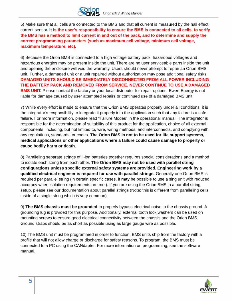
5) Make sure that all cells are connected to the BMS and that all current is measured by the hall effect
current sensor. It is the user’s responsibility to ensure the BMS is connected to all cells, to verify
the BMS has a method to limit current in and out of the pack, and to determine and supply the
correct programming parameters (such as maximum cell voltage, minimum cell voltage,
maximum temperature, etc).
6) Because the Orion BMS is connected to a high voltage battery pack, hazardous voltages and
hazardous energies may be present inside the unit. There are no user serviceable parts inside the unit
and opening the enclosure will void the warranty. Users should never attempt to repair an Orion BMS
unit. Further, a damaged unit or a unit repaired without authorization may pose additional safety risks.
DAMAGED UNITS SHOULD BE IMMEDIATELY DISCONNECTED FROM ALL POWER INCLUDING
THE BATTERY PACK AND REMOVED FROM SERVICE. NEVER CONTINUE TO USE A DAMAGED
BMS UNIT. Please contact the factory or your local distributor for repair options. Ewert Energy is not
liable for damage caused by user attempted repairs or continued use of a damaged BMS unit.
7) While every effort is made to ensure that the Orion BMS operates properly under all conditions, it is
the integrator’s responsibility to integrate it properly into the application such that any failure is a safe
failure. For more information, please read “Failure Modes” in the operational manual. The integrator is
responsible for the determination of suitability of this product for the application, choice of all external
components, including, but not limited to, wire, wiring methods, and interconnects, and complying with
any regulations, standards, or codes. The Orion BMS is not to be used for life support systems,
medical applications or other applications where a failure could cause damage to property or
cause bodily harm or death.
8) Paralleling separate strings of li-ion batteries together requires special considerations and a method
to isolate each string from each other. The Orion BMS may not be used with parallel string
configurations unless specific external safety systems are provided. Engineering work by a
qualified electrical engineer is required for use with parallel strings. Generally one Orion BMS is
required per parallel string (in certain specific cases, it may be possible to use a sing unit with reduced
accuracy when isolation requirements are met). If you are using the Orion BMS in a parallel string
setup, please see our documentation about parallel strings (Note: this is different from paralleling cells
inside of a single string which is very common).
9) The BMS chassis must be grounded to properly bypass electrical noise to the chassis ground. A
grounding lug is provided for this purpose. Additionally, external tooth lock washers can be used on
mounting screws to ensure good electrical connectivity between the chassis and the Orion BMS.
Ground straps should be as short as possible using as large gauge wire as possible.
10) The BMS unit must be programmed in order to function. BMS units ship from the factory with a
profile that will not allow charge or discharge for safety reasons. To program, the BMS must be
connected to a PC using the CANdapter. For more information on programming, see the software
manual.

Orion BMS Wiring Manual
6
ALWAYS READ THE MANUAL BEFORE USE.
The most up-todate Orion BMS manuals can be downloaded at: www.orionbms.com/downloads
Orion BMS Wiring Manual
7
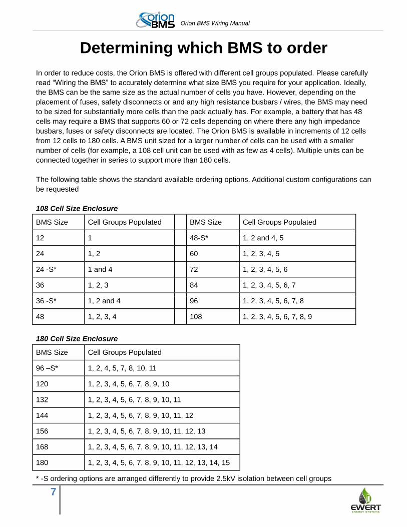
Determining which BMS to order
In order to reduce costs, the Orion BMS is offered with different cell groups populated. Please carefully
read “Wiring the BMS” to accurately determine what size BMS you require for your application. Ideally,
the BMS can be the same size as the actual number of cells you have. However, depending on the
placement of fuses, safety disconnects or and any high resistance busbars / wires, the BMS may need
to be sized for substantially more cells than the pack actually has. For example, a battery that has 48
cells may require a BMS that supports 60 or 72 cells depending on where there any high impedance
busbars, fuses or safety disconnects are located. The Orion BMS is available in increments of 12 cells
from 12 cells to 180 cells. A BMS unit sized for a larger number of cells can be used with a smaller
number of cells (for example, a 108 cell unit can be used with as few as 4 cells). Multiple units can be
connected together in series to support more than 180 cells.
The following table shows the standard available ordering options. Additional custom configurations can
be requested
108 Cell Size Enclosure
BMS Size Cell Groups Populated BMS Size Cell Groups Populated
12 1 48-S* 1, 2 and 4, 5
24 1, 2 60 1, 2, 3, 4, 5
24 -S* 1 and 4 72 1, 2, 3, 4, 5, 6
36 1, 2, 3 84 1, 2, 3, 4, 5, 6, 7
36 -S* 1, 2 and 4 96 1, 2, 3, 4, 5, 6, 7, 8
48 1, 2, 3, 4 108 1, 2, 3, 4, 5, 6, 7, 8, 9
180 Cell Size Enclosure
BMS Size Cell Groups Populated
96 –S* 1, 2, 4, 5, 7, 8, 10, 11
120 1, 2, 3, 4, 5, 6, 7, 8, 9, 10
132 1, 2, 3, 4, 5, 6, 7, 8, 9, 10, 11
144 1, 2, 3, 4, 5, 6, 7, 8, 9, 10, 11, 12
156 1, 2, 3, 4, 5, 6, 7, 8, 9, 10, 11, 12, 13
168 1, 2, 3, 4, 5, 6, 7, 8, 9, 10, 11, 12, 13, 14
180 1, 2, 3, 4, 5, 6, 7, 8, 9, 10, 11, 12, 13, 14, 15
* -S ordering options are arranged differently to provide 2.5kV isolation between cell groups

Orion BMS Wiring Manual
8
Included with the standard BMS
Hardware
Voltage tap connectors & crimps (number depends on the number of cells ordered)
Power connector & crimps
Current sensor connector & crimps (BMS side); current sensor side included if current sensor is
ordered with BMS.
HV Pack voltage sensor connector & crimps
Ordering Options
The Orion BMS is available with different number of cell groups populated to reduce costs. For
example, a BMS with 72 cells is available such that an application requiring less than that does not
require a 108 cell version.
Non standard CAN termination point options
Two size enclosures are available - maximum of 108 or 180 cells
Current sensor options +/- 200A, 500A, 750A and 1000A
Various thermistor options are available
Pre-assembled wiring harnesses are available
Basic displays, data loggers and PC interfaces are also options.
See “Purchasing Guide” for details on ordering options

Orion BMS Wiring Manual
9
Theory of Operation
The Orion BMS protects and monitors a battery pack by monitoring several sensors and uses several
outputs to control charge and discharge into the battery. The BMS measures inputs from cell voltage
taps, the total pack voltage tap, a hall effect current sensor and thermistors. Using the programmed
settings, the BMS then controls the flow of current into and out of the battery pack through broadcasting
charge and discharge current limits (via the CANBUS or via analog reference voltages) or via simple
on/off digital signals depending on which style is appropriate for the application. The BMS relies on the
user to provide external controls that respect the current limits set by the BMS to protect the batteries
as the BMS does not have integrated switches. During and immediately after charging, the BMS will
balance the cells using internal shunt resistors based on the programmed settings.
The Orion unit monitors each individual cell tap to insure that cell voltages are not too high or too low
(in accordance with the values programmed in). Using the cell voltages, the amperage going in and out
of the pack (provided by the current sensor) and programmed values in the battery pack profile the
BMS calculates the pack and individual cell’s internal resistance, and open cell voltages. From those
calculations, the maximum charge and discharge current limits are calculated and adjustments are
made to the pack’s calculated state of charge if necessary. These calculations are also used in
monitoring the health of the pack. Charge and discharge current limits are provided on the CANBUS
and can be programmed to trigger on/off digital outputs to allow or deny charging and discharging of
the battery pack.
Additionally, the BMS has many redundant safeties, most of which are transparent to the user. For
example, the BMS monitors each individual cell voltage as well as the total pack voltage. If the two
voltages disagree by a set amount (determined in the programmable profile), the BMS will set an error
code and go into a fail safe mode. The BMS also can be programmed to monitor for a breakdown in
isolation between the battery pack and BMS’s ground, to detect a failure of the current sensor and
many other internal failures. Please see “failure modes” in the operational manual for more information
on failure modes.
Orion BMS Wiring Manual
10
Mounting
Physical Mounting The Orion BMS can be mounted in any orientation. Six mounting holes are provided on the mounting
flanges of the BMS. The BMS is rated for the automotive temperature range of -40C to +80C and is
designed for use in moderately protected locations such as inside the passenger compartment of a
vehicle. If the BMS will be exposed to harsh environments such as sprayed liquids, salt spray or other
similar conditions, it must be located inside a suitable protective sealed rated enclosure. It should be
noted that lithium batteries themselves also must typically be protected from these harsh environmental
elements.
Thermal & Ventilation Information
The Orion BMS requires unobstructed, adequate ventilation and must not be surrounded or
sealed by thermal insulating material. Blocking ventilation or thermally insulating the unti may
pose a fire hazard.
While the BMS has a fairly significant looking heatsink, the BMS is designed to dissipate all heat
generated via convection in hot environments, and therefore does not generate as much heat as might
be expected from such a large heatsink. A 108 cell BMS unit generates up to 40 watts of heat and a
180 cell unit generates a maximum of 60 watts of heat average under normal use while balancing.
Significant amounts of heat are only generated during the balancing phase during charge. Heat
dissipation under non-balancing conditions is only about 2 - 3 watts. The Orion BMS is equipped to
measure the internal temperature of the unit and will automatically reduce balancing current if the
temperature rises too high. However, the BMS must be installed such that is has adequate ventilation
to dissipate up to 40 watts for 108 cell and smaller units and 60 watts for 120 cell and larger units safely
without causing significant temperature rise. During certain abnormal fault conditions, the unit has the
potential to generate as much as 40 watts of heat. Ventilation must be adequate for this amount of heat
even though this will not be generated under normal use. The thermal dissipation should be considered
if the BMS will be enclosed in a liquid tight enclosure.
Ground Lug A ground lug is provided on the outside of the enclosure. The BMS MUST be grounded to a vehicle
chassis or Earth ground (if stationary) for proper electrical noise rejection. In applications which
do not have a grounded chassis, the chassis of the BMS must still be grounded for proper noise
handling. In most of these cases, the ground lug can be connected to the 12v power supply negative. If
noise persists with the ground lug connected to the negative on the 12v power supply, it may be
necessary to identify the noise source and evaluate a different grounding path.
Orion BMS Wiring Manual
11
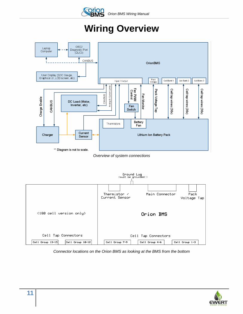
Wiring Overview
Overview of system connections
Connector locations on the Orion BMS as looking at the BMS from the bottom
Orion BMS Wiring Manual
12
Connectors, Crimps, and Tooling
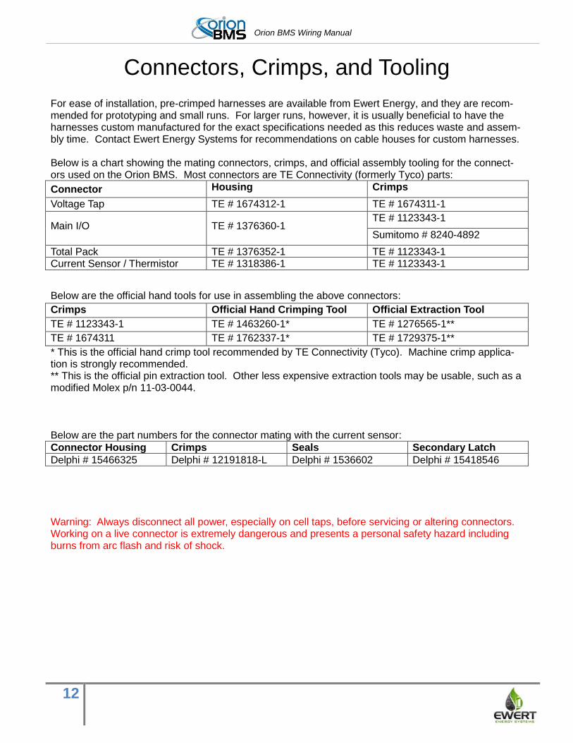
For ease of installation, pre-crimped harnesses are available from Ewert Energy, and they are recom-mended for prototyping and small runs. For larger runs, however, it is usually beneficial to have the harnesses custom manufactured for the exact specifications needed as this reduces waste and assem-bly time. Contact Ewert Energy Systems for recommendations on cable houses for custom harnesses. Below is a chart showing the mating connectors, crimps, and official assembly tooling for the connect-ors used on the Orion BMS. Most connectors are TE Connectivity (formerly Tyco) parts:
Connector Housing Crimps
Voltage Tap TE # 1674312-1 TE # 1674311-1
Main I/O TE # 1376360-1 TE # 1123343-1
Sumitomo # 8240-4892
Total Pack TE # 1376352-1 TE # 1123343-1 Current Sensor / Thermistor TE # 1318386-1 TE # 1123343-1
Below are the official hand tools for use in assembling the above connectors:
Crimps Official Hand Crimping Tool Official Extraction Tool
TE # 1123343-1 TE # 1463260-1* TE # 1276565-1**
TE # 1674311 TE # 1762337-1* TE # 1729375-1**
* This is the official hand crimp tool recommended by TE Connectivity (Tyco). Machine crimp applica-tion is strongly recommended. ** This is the official pin extraction tool. Other less expensive extraction tools may be usable, such as a modified Molex p/n 11-03-0044. Below are the part numbers for the connector mating with the current sensor:
Connector Housing Crimps Seals Secondary Latch
Delphi # 15466325 Delphi # 12191818-L Delphi # 1536602 Delphi # 15418546
Warning: Always disconnect all power, especially on cell taps, before servicing or altering connectors. Working on a live connector is extremely dangerous and presents a personal safety hazard including burns from arc flash and risk of shock.
Orion BMS Wiring Manual
13
Interfacing the Load and Charger with the BMS
The Orion BMS constantly calculates maximum current limits for both charging and discharging. These
current limits are based on many parameters including pre-programmed maximum amperages (usually
specified by the cell manufacture), temperature, cell health, state of charge, and several other condi-
tions. The current limits are automatically determined based on a calculated algorithm to prevent the
cell voltages from dropping below or going above the minimum and maximum cell voltages respective-
ly. More information on how the current limits are calculated can be found in the operational manual.
While the BMS can accurately calculate current limits to keep the connected cells within safe operating
parameters, the BMS unit itself cannot directly enforce these current limits (ie: it is up to the load and
charger to respect the limits that the BMS sets). For this, the BMS relies on the installer to provide a
means to limit charge and discharge current and can only protect cells when this external means of lim-
iting current is properly connected. The BMS must be able to turn off all charge and all discharge to the
battery pack in order to properly protect the cells. Failure to provide an external method to limit
charge and discharge current will result in the BMS not being able to protect the connected
cells. Below are the three main methods of controlling a load or charge source.
Current Limiting via the digital CANBUS (Controller Area Network) Many modern chargers, motor controllers, solar/wind inverters, and other equipment come with a digital
CANBUS interface. This digital protocol usually has a method of communicating maximum current lim-
it(s) to the device. For example, almost all CANBUS enabled battery chargers will listen to the BMS and
charge at an amperage not to exceed the amperage the BMS instructs them. Likewise, almost all CAN
enabled motor controllers can be configured to listen to the BMS and limit the amount of current the
motor can draw to the amperage that the BMS specifies. Motor controllers that support regenerative
braking usually will also listen for a maximum charge current in order to limit regenerative braking am-
perage.
Interfacing with external devices via CANBUS has some significant advantages and is generally the
preferred method of controlling external devices whenever a CAN interface is available (with a few ex-
ceptions). Because CAN is a digital protocol, the BMS can accurately and quickly specify the current
limit to the device. This is particularly useful for applications where a gradual reduction of power either
at the end of discharge or end of charge is beneficial or necessary and takes full advantage of the Ori-
on BMS’s capabilities. For example, if the BMS is being used in a vehicle, it is desirable for the vehicle
to gradually slow down when the battery is exhausted rather than suddenly cut out when the battery is
depleted. This also allows a greater portion of the battery to be used. Gradual current limiting is neces-
sary to fully charge a battery pack to 100% state of charge (although in most applications it is desirable
only to charge to a maximum of 95% for lifespan reasons, which may not require gradual tapering of
the charge in lithium batteries).
The Orion BMS utility has built-in support for many CAN enabled chargers and motor controllers and
has an extremely programmable CAN interface which can be programmed for devices that are not al-
ready integrated.
Orion BMS Wiring Manual
14
Current limiting via the analog voltage outputs. The Orion BMS is equipped with two analog voltage outputs which can be used to communicate the
amperage limits to external devices. Pin 16 (Discharge Current Limit or DCL) and Pin 5 (Charge Cur-
rent Limit or CCL) are both outputs which range from 0 to 5 volts and provide an analog representation
of the maximum current limits (0V = 0%, 5V = 100% of the maximum limit). If a motor controller does
not support CAN, but has a 5V potentiometer for a throttle, it may be possible to use the 0-5V output
from the BMS to limit the maximum voltage on the potentiometer and therefore effectively limit current.
The BMS can interface with devices requiring a 0-10V signal with the addition of external op-amp circuit
to translate the voltage.
Important: Whenever the 0-5V analog outputs are used for controlling current, they must be used in
conjunction with the charge or discharge enable outputs from the BMS as a backup to ensure the BMS
can fully turn off the device since the analog 0-5V outputs are not watchdog backed and could poten-
tially lock at a certain voltage in a failure. See “Wiring the Main I/O” below for more information.
Current limiting via an on/off signal from the BMS. The simplest method to control a load or charger is by using the on / off outputs. These outputs will turn
on when charge or discharge are allowed based on the present conditions. Unlike the other above
methods of controlling external devices, these outputs are either on or off and cannot gradually taper
charge or discharge (though they can be used in conjunction with the other methods). There are 3 on /
off outputs: Charger safety enable, discharge enable and charge enable. Charger safety enable is used
to control a battery charger; discharge enable is used to control a load such a motor controller or AC
inverter; and charge enable is used to turn off intermittent charging currents such as charge from re-
generative braking.
More information about how the outputs are wired and how they function can be found later in this
manual as well as in the operational manual. Information on changing the setting for when these out-
puts are on can be found in the software manual.
Notes for specific applications Application notes are available for integrating with many common motor controllers and chargers and
include information, tips and recommended wiring specific to those devices. Application notes can be
viewed at http://www.orionbms.com/application-notes/
Orion BMS Wiring Manual
15
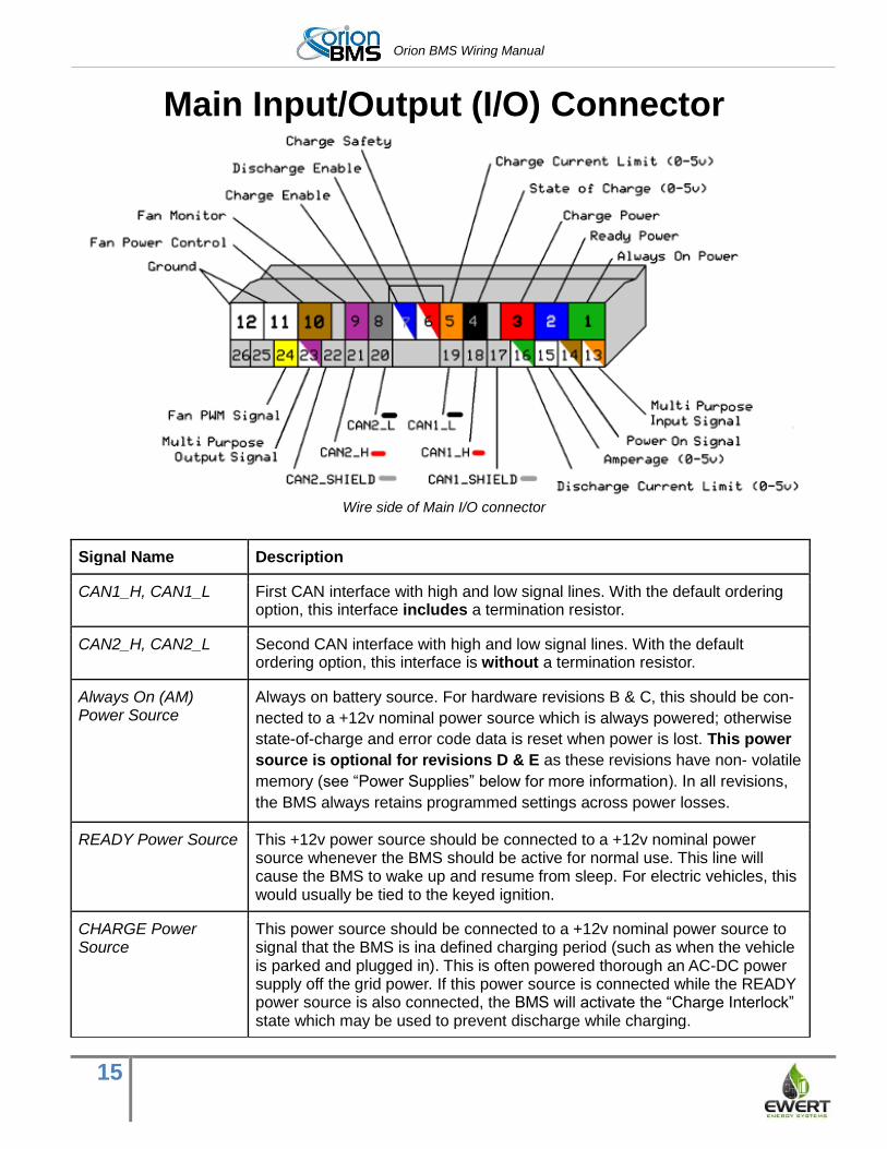
Main Input/Output (I/O) Connector
Wire side of Main I/O connector
Signal Name Description
CAN1_H, CAN1_L First CAN interface with high and low signal lines. With the default ordering option, this interface includes a termination resistor.
CAN2_H, CAN2_L Second CAN interface with high and low signal lines. With the default ordering option, this interface is without a termination resistor.
Always On (AM) Power Source
Always on battery source. For hardware revisions B & C, this should be con-
nected to a +12v nominal power source which is always powered; otherwise
state-of-charge and error code data is reset when power is lost. This power
source is optional for revisions D & E as these revisions have non- volatile
memory (see “Power Supplies” below for more information). In all revisions,
the BMS always retains programmed settings across power losses.
READY Power Source This +12v power source should be connected to a +12v nominal power source whenever the BMS should be active for normal use. This line will cause the BMS to wake up and resume from sleep. For electric vehicles, this would usually be tied to the keyed ignition.
CHARGE Power Source
This power source should be connected to a +12v nominal power source to signal that the BMS is ina defined charging period (such as when the vehicle is parked and plugged in). This is often powered thorough an AC-DC power supply off the grid power. If this power source is connected while the READY power source is also connected, the BMS will activate the “Charge Interlock” state which may be used to prevent discharge while charging.
Orion BMS Wiring Manual
16
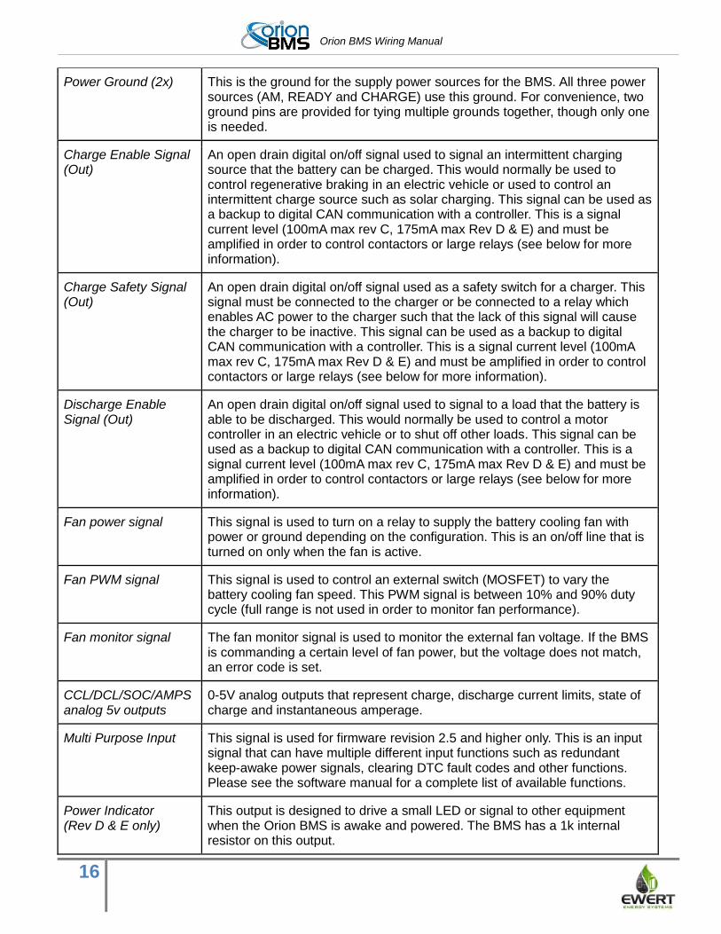
Power Ground (2x) This is the ground for the supply power sources for the BMS. All three power sources (AM, READY and CHARGE) use this ground. For convenience, two ground pins are provided for tying multiple grounds together, though only one is needed.
Charge Enable Signal (Out)
An open drain digital on/off signal used to signal an intermittent charging source that the battery can be charged. This would normally be used to control regenerative braking in an electric vehicle or used to control an intermittent charge source such as solar charging. This signal can be used as a backup to digital CAN communication with a controller. This is a signal current level (100mA max rev C, 175mA max Rev D & E) and must be amplified in order to control contactors or large relays (see below for more information).
Charge Safety Signal (Out)
An open drain digital on/off signal used as a safety switch for a charger. This signal must be connected to the charger or be connected to a relay which enables AC power to the charger such that the lack of this signal will cause the charger to be inactive. This signal can be used as a backup to digital CAN communication with a controller. This is a signal current level (100mA max rev C, 175mA max Rev D & E) and must be amplified in order to control contactors or large relays (see below for more information).
Discharge Enable Signal (Out)
An open drain digital on/off signal used to signal to a load that the battery is able to be discharged. This would normally be used to control a motor controller in an electric vehicle or to shut off other loads. This signal can be used as a backup to digital CAN communication with a controller. This is a signal current level (100mA max rev C, 175mA max Rev D & E) and must be amplified in order to control contactors or large relays (see below for more information).
Fan power signal This signal is used to turn on a relay to supply the battery cooling fan with power or ground depending on the configuration. This is an on/off line that is turned on only when the fan is active.
Fan PWM signal This signal is used to control an external switch (MOSFET) to vary the battery cooling fan speed. This PWM signal is between 10% and 90% duty cycle (full range is not used in order to monitor fan performance).
Fan monitor signal The fan monitor signal is used to monitor the external fan voltage. If the BMS is commanding a certain level of fan power, but the voltage does not match, an error code is set.
CCL/DCL/SOC/AMPS analog 5v outputs
0-5V analog outputs that represent charge, discharge current limits, state of charge and instantaneous amperage.
Multi Purpose Input This signal is used for firmware revision 2.5 and higher only. This is an input signal that can have multiple different input functions such as redundant keep-awake power signals, clearing DTC fault codes and other functions. Please see the software manual for a complete list of available functions.
Power Indicator (Rev D & E only)
This output is designed to drive a small LED or signal to other equipment when the Orion BMS is awake and powered. The BMS has a 1k internal resistor on this output.

Orion BMS Wiring Manual
17
Multi Purpose Output (Rev D & E only)
The behavior of this multi-purpose output is configured in software for additional functionality. This output is often used to drive an LED to indicate the presence of error codes, but can also be used as a CAN controlled output as well as other functions. Please see the software manual for a complete list of available functions. This output is NOT watchdog backed and may remain on when certain faults occur. This output should not be used as the sole control for limiting charge or discharge
Orion BMS Wiring Manual
18
Wiring the Main I/O Connector
Power Supplies 12V operating power is supplied to the Orion BMS by three separate power sources - one always on
power supply and two primary power supplies. The three power supplies will not backfeed each other
due to internal diodes contained within the BMS. The Orion BMS consumes approximately 250mA at a
nominal 12 volts (9v - 16v range acceptable) for operating current. Operating current may be higher if
additional devices are connected to the Orion BMS.
Fusing Important: As with all electrical devices, the wires carrying operating current to the Orion BMS unit
must be current limited at their source, including wires feeding current to relays driven by the BMS. Any
circuit connecting to the BMS must be current limited with an appropriately sized fuse (or other current
limiting device) to prevent overloading wires in the event of a short. The external fuse must be sized
properly to protect the conductors and must specifically have a DC voltage rating of no less than the
maximum possible working voltage and an appropriate DC interrupting current rating for the application.
The maximum fuse size permitted for the CHARGE or READY power, any of the open drain output
pins, or multi-purpose input pins in 5A, but smaller fuses may be used.
All three power supplies should be supplied with a nominal 12 volts. Voltages between 9V and 16V are
acceptable for continuous operation. On hardware revisions B & C, voltages below 9V will cause some
features on the unit to temporarily stop operating until voltages have recovered and voltages above 16v
can cause damage to the unit.
Hardware revisions D and newer units have expanded brownout protection. While the startup and
continuous operating voltage range remains 9v to 16v, these new hardware revisions can fully operate
at voltages as low as 5v for a minimum of 120 seconds, surpassing ISO 7637 “cold crank”
requirements. It should be noted that while the unit will fully function at voltages less than 9v for several
minutes, the unit is not designed for continuous operation at these lower voltages and an error code will
be set by the unit if the voltage is less than 9v for more than 8 seconds. The Orion BMS unit will
consume more power when supply voltage drops below 9v. Additionally, these revisions can continue to
operate without any power source for up to 100mS (when the starting voltage is 12v or higher when
power is removed). As a result of this, “power cycling” the BMS may require 30 seconds or longer.
Hardware revisions D and newer units also feature expanded transient protection. Revision D and E
units can fully operate through the highest class passenger vehicle load dump ISO 7637 Class IV
(87V, 400mS, 0.5 ohm source).
Always On Power Source: This power source is used to retain system memory when the BMS is
asleep, as well as being a redundant power supply in case the main power source fails. Hardware
revisions B & C require this pin to be connected to an always-on +12v power source for the BMS unit to
retain data (state of charge, error codes, battery health information, etc.) in internal memory with the
Orion BMS Wiring Manual
19
other power sources are disconnected. Hardware revisions D & E can retain data without power in non-
volatile memory, making this connection optional for those hardware revisions. In order to take
advantage of this non-volatile memory feature and to prevent the BMS from setting error codes, the
“disable always-on power supply” option must be selected in the software utility. The always on power
source is recommended when possible for revisions D & E and is necessary for applications either
requiring a startup time of less than 250mS or requiring redundant power for the BMS. In all revisions of
the BMS, programmed settings are retained across power losses.
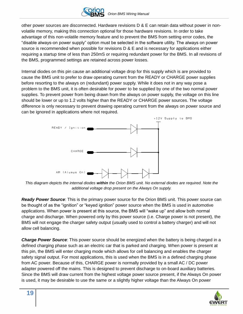
Internal diodes on this pin cause an additional voltage drop for this supply which is are provided to
cause the BMS unit to prefer to draw operating current from the READY or CHARGE power supplies
before resorting to the always on (redundant) power supply. While it does not in any way pose a
problem to the BMS unit, it is often desirable for power to be supplied by one of the two normal power
supplies. To prevent power from being drawn from the always on power supply, the voltage on this line
should be lower or up to 1.2 volts higher than the READY or CHARGE power sources. The voltage
difference is only necessary to prevent drawing operating current from the always on power source and
can be ignored in applications where not required.
This diagram depicts the internal diodes within the Orion BMS unit. No external diodes are required. Note the
additional voltage drop present on the Always On supply.
Ready Power Source: This is the primary power source for the Orion BMS unit. This power source can
be thought of as the “ignition” or “keyed ignition” power source when the BMS is used in automotive
applications. When power is present at this source, the BMS will “wake up” and allow both normal
charge and discharge. When powered only by this power source (i.e. Charge power is not present), the
BMS will not engage the charger safety output (usually used to control a battery charger) and will not
allow cell balancing.
Charge Power Source: This power source should be energized when the battery is being charged in a
defined charging phase such as an electric car that is parked and charging. When power is present at
this pin, the BMS will enter charging mode which allows for cell balancing and enables the charger
safety signal output. For most applications, this is used when the BMS is in a defined charging phase
from AC power. Because of this, CHARGE power is normally provided by a small AC / DC power
adapter powered off the mains. This is designed to prevent discharge to on-board auxiliary batteries.
Since the BMS will draw current from the highest voltage power source present, if the Always On power
is used, it may be desirable to use the same or a slightly higher voltage than the Always On power
Orion BMS Wiring Manual
20
source. This will prevent the BMS from drawing current from the Always On source and is important if
draining an auxiliary battery is a concern.
The BMS will fully operate and will enter charging mode when both the CHARGE and READY power
sources are powered at the same time. However, when both the CHARGE and READY are powered at
the same time, the BMS will enter into charge interlock mode. Charge interlock is designed as a
mechanism to prevent a vehicle from driving away while plugged in and can be used to prohibit
discharge (see discharge enable relay settings in the BMS utility). Depending on the programmed
setting, when the BMS is in charge interlock mode, the error status can be turned on when in charge
interlock mode even though no fault code is set (this setting is changed on the Fault Settings tab in the
BMS utility). All other functionality of the BMS will remain the same when both CHARGE and READY
power sources are present at the same time.
Voltages are sensed by the BMS at each of the power sources, including the always on source. If
power is present only on the always on power source, while CHARGE and READY are both off, the
BMS will enter a low power sleep mode within a few seconds. If power is present at either the CHARGE
or READY power sources, but not at the always on power source, the BMS will operate normally.
However, depending on a programmable setting (Rev. D & E only) a diagnostic trouble code may be set
on the BMS to alert the operator that the always on power is missing In applications with revision D
units that do not have always on power, this error code can be disabled in the software by selecting
“disable always-on power supply” option or “always on power source not used” under general settings
in the BMS utility.
In some applications such as non-automotive applications where the BMS is powered by a single
power supply or an automotive application with a secondary charger or DC-DC converter topping off
the 12v auxiliary battery, it may be more convenient to wake the BMS up using a low current signal
rather than supply the full operating current. In this situation, a 1K resistor can be put in series with the
CHARGE or READY power supplies. The BMS will detect the voltage at the power source pins, but will
be unable to draw operating current from the power source pins due to the 1K series resistor. While this
method will not provide redundant power supplies to the BMS, it will wake up the BMS and cause it to
draw operating current from the always on power source and may be more convenient for some
applications.
Redundancy Power Option: All hardware revisions of the Orion BMS with firmware versions 2.4.10
and newer support a redundant keep-alive option that makes use of the Multi-Purpose Input pin (Main
I/O pin 13). This option is designed to keep the BMS “awake” in the event that a power failure occurs to
the Ready or Charge power source, but not to the always on power source. Applying a voltage to this
pin will not wake up the BMS if it is already asleep, but it will prevent the BMS from going to sleep if it is
already active. This feature is enabled by default in the software profile, but it can be disabled in
software if desired.
CAN interfaces The Orion BMS has two separate CAN (controller area network) interfaces - CAN1 and CAN2. The two
interfaces are not connected internally and can operate at different baud rates and can transmit and
Orion BMS Wiring Manual
21
receive different messages. This is particularly useful if the application has multiple CANBUSes with
different baud-rates. The CANBUS interfaces can be configured to run at 125, 250, 500 or 1000 Kbps.
CAN interfaces are differential mode buses and require twisted pair wire (2 wires) to communicate. For
best operation, a shielded cable should be used for protection against electrical noise immunity,
particularly when used in vehicles or around other noisy devices. For convenience, two locations are
provided on the Orion BMS connector to terminate the shields on the cables. Shields should only be
connected in one location to prevent ground loops, so if the shield grounding locations are used on the
Orion BMS connector, the shields should not be connected anywhere else. Some applications may
require grounding of the shields in locations other than the Orion BMS connector to properly divert
noise, and it is the integrator’s responsibility to determine if this is necessary. While it is necessary for
the wires to be outside of the shield for a short distance at any connectors, the amount of non shielded,
non-twisted wire should be kept as short as possible, ideally a couple inches or less as even very short
sections of exposed CANBUS wiring can cause communication errors in high noise environments.
Any external devices connected to the Orion BMS’s CAN interface must share a common ground with
the BMS (Main I/O connector pin 12). This is important as differences in ground potentials can damage
the CAN transceivers on the BMS and on other devices. If it is not possible to use the same ground,
external CAN isolations device must be used. Please note that while the low voltage electronics in
the BMS are electrically isolated from the battery pack, the CAN transceivers are referenced to
the 12v power supply ground and are not electrically isolated from the 12v power supply ground
or from each other. If the BMS is connected to motor controllers, chargers, or other devices which do
not offer isolation between the high voltage battery pack and the CANB US (or any other low voltage
signals that are connected to the BMS), an external isolation may be required for safety. For more
information, please see “Internal Isolation” below for an isolation diagram.
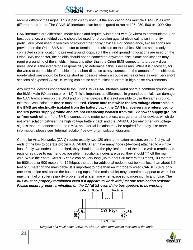
Controller Area Networks (CAN) require exactly two 120 ohm termination resistors on the 2 physical
ends of the bus to operate properly. A CANBUS can have many nodes (devices) attached to a single
bus. If only two nodes are attached, they should be at the physical ends of the cable with a termination
resistor as close to each end as possible. If additional nodes are used, they should “T” off the main
wire. While the entire CANBUS cable can be very long (up to about 30 meters for 1mpbs,100 meters
for 500kbps, or 500 meters for 125kbps), the taps for additional nodes must be kept less than about 3.5
feet or 1 meter off the main cable. It is important to note than an improperly wired CANBUS (e.g. only
one termination resistor on the bus or long taps off the main cable) may sometimes appear to work, but
may then fail or suffer reliability problems at a later time when exposed to more significant noise. The
bus must be properly terminated even if it appears to work with just one termination resistor!
Please ensure proper termination on the CANBUS even if the bus appears to be working.
Diagram of a multi-node CANBUS with 120 ohm termination resistors at the ends
Orion BMS Wiring Manual
22
For convenience, the CAN1 interface on the Orion BMS (unless specially ordered) has one (1) 120 ohm
terminator resistor built into the unit, whereas the CAN2 interface does not, allowing the default Orion
BMS unit to be easily integrated either at the physical end of a bus (CAN1 interface) or in the middle of
an existing bus (CAN2 interface). Since the BMS includes one of the two necessary termination
resistors, at least one additional termination resistor is required on the network so that the CANBUS
has exactly two termination resistors (termination resistors are not required on an interface if it is not
used). Some other devices such as motor controllers may have integrated termination resistors. Please
consult the manual for other devices to determine if they have termination resistors. The Orion BMS
can be special ordered with specific termination resistors loaded or unloaded, but this must be done at
the time of ordering.
The two CAN interfaces are functionally the same with the one exception that only the CAN1 interface
may be used to perform field updates on the BMS firmware. The BMS profile & settings may be
updated from either CAN interface, but the actual firmware software on the BMS can only be updated
via CAN1. For this reason, it is recommended that CAN1 be used to interface with any diagnostic
connectors or DB9 connectors (to connect to the CANdapter).
After wiring the CAN interfaces, it is possible to verify proper termination by using an ohm-meter to
check the resistance between CAN_H and CAN_L. In order to verify the resistance, all power must be
removed from all devices on the CANBUS. The total resistance should measure 60 ohms (two 120 ohm
resistors in parallel = 60 ohms).
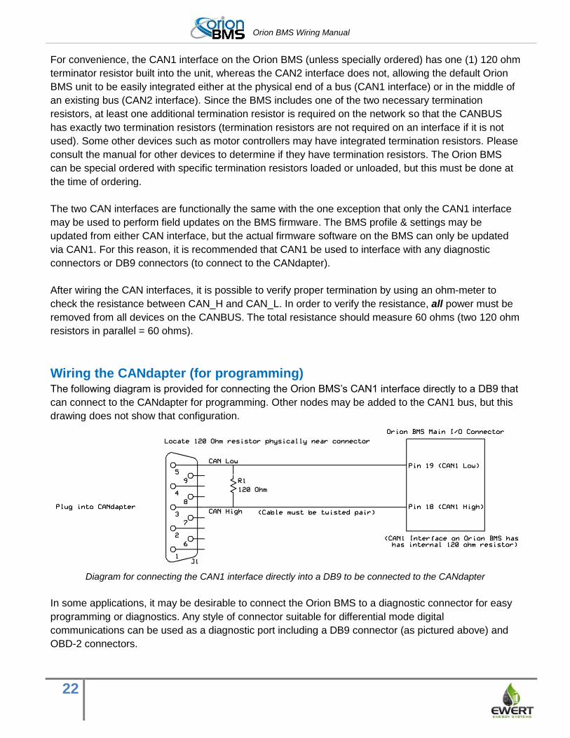
Wiring the CANdapter (for programming) The following diagram is provided for connecting the Orion BMS’s CAN1 interface directly to a DB9 that
can connect to the CANdapter for programming. Other nodes may be added to the CAN1 bus, but this
drawing does not show that configuration.
Diagram for connecting the CAN1 interface directly into a DB9 to be connected to the CANdapter
In some applications, it may be desirable to connect the Orion BMS to a diagnostic connector for easy
programming or diagnostics. Any style of connector suitable for differential mode digital
communications can be used as a diagnostic port including a DB9 connector (as pictured above) and
OBD-2 connectors.
Orion BMS Wiring Manual
23
Digital signal outputs The Orion BMS has three signal level digital I/O outputs designed to control charging and discharging -
Charge Enable, Discharge Enable and Charger Safety – along with one multi-purpose output with a
software assignable function. The Charge Enable, Discharge Enable, and Charger Safety outputs are
backed by a watchdog that will shut the outputs off in the event of a processor malfunction, adding an
extra layer of safety. Only the Charge Enable, Discharge Enable, and Charger Safety outputs should be
used to control charge and discharge as the multi-purpose output does not have the watchdog
protection and may not turn off during certain faults. It is important to note that in addition to using
these outputs (or the CANBUS equivalent), the integrator must provide an additional external method of
stopping charge and discharge should any of these outputs fail. An example of this is a programmed
maximum pack voltage on a charger or a minimum / maximum pack voltage on a motor controller. Pack
voltages are only to be used as a backup should the primary method of control fail. Never rely solely on
the pack voltage for determining when to start or end charge or discharge.
These outputs are open drain outputs which means that they do not source any current or voltage, but
rather pull down to ground and sink current when they are turned on. While this may seem like an odd
way to interface with the BMS, this method provides greater flexibility and can interface with a wide
range of applications using different voltages up to 24V. These three outputs pull low when they are
enabled and, with the exception of the multi-purpose output, cannot be inverted in software for safety
reasons. This is done such that if the BMS connecter were to become disconnected, the outputs would
fail off rather than on. For safety reasons, each of these three outputs feature an analog watchdog
circuit which turns the outputs off in the event of a processor malfunction adding an extra layer of
safety.
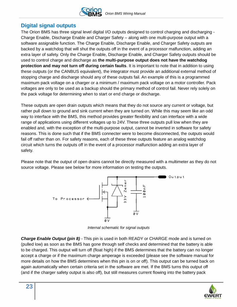
Please note that the output of open drains cannot be directly measured with a multimeter as they do not
source voltage. Please see below for more information on testing the outputs.
Internal schematic for signal outputs
Charge Enable Output (pin 8) - This pin is used in both READY or CHARGE mode and is turned on
(pulled low) as soon as the BMS has gone through self checks and determined that the battery is able
to be charged. This output will turn off (float high) if the BMS determines that the battery can no longer
accept a charge or if the maximum charge amperage is exceeded (please see the software manual for
more details on how the BMS determines when this pin is on or off). This output can be turned back on
again automatically when certain criteria set in the software are met. If the BMS turns this output off
(and if the charger safety output is also off), but still measures current flowing into the battery pack
Orion BMS Wiring Manual
24
afterwards, a critical error will be set on the BMS resulting in the disabling of all charge and discharge
until the BMS has been reset as a safety feature.
Important note: In addition to using this output, any charge source should be set such that it will shut
off in the even the maximum pack voltage is reached as a secondary precaution against overcharge.
While this is an important backup, never rely solely on the pack voltage to turn off charge sources and
always ensure the BMS can turn off all charge sources.
Discharge Enable Output (pin 7) - This pin is used in both READY or CHARGE mode and is turned
on (pulled low) as soon as the BMS has gone through self checks and determined that the battery is
able to be discharged. This output will turn off (float high) if the BMS determines that the battery can no
longer provide current or if the maximum discharge amperage is exceeded (please see the software
manual for more details on how the BMS determines when this pin is on or off). This output can be
turned back on again automatically when certain criteria set in the software are met. If the BMS turns
this output off, but still measures current flowing out of the battery pack afterwards, a critical error will
be set on the BMS resulting in the disabling of all charge and discharge until the BMS has been reset.
Important note: In addition to using this output, any load should be set such that it will shut off in the
event the minimum pack voltage is reached as a secondary precaution against over-discharge. An
entire lithium ion battery pack can be destroyed in a single cycle form over-discharge. While this is an
important backup, never rely solely on the pack voltage to turn off loads and always ensure the BMS
can turn off all loads.
Charger Safety Output (pin 6) - This pin is used only in CHARGE mode and is used to control when a
charger is turned on. Once the CHARGE power supply is detected by the Orion BMS, the BMS will go
through self checks and ensure that the battery can accept a charge. The charger safety output will
not turn on unless CHARGE power is applied to the BMS. Once the BMS passes all the tests, this
output is turned on (pulled low) to enable the charger. Once the battery has reached its maximum
voltage, this output is turned off (float). This output can be turned back on again during balancing or at
set intervals when certain criteria set in the software are met. If the BMS turns this output off (and if the
charge enable output is also off or disabled, but the BMS still measures current flowing out of the
battery pack afterwards, a critical error will be set on the BMS resulting in the disabling of all charge
and discharge until the BMS has been reset. The status of this pin can be transmitted via the CANBUS.
Important safety note: At least two shutoff mechanisms should be present to turn off a charger. The
charger safety signal is designed to be used as a backup if a digital CAN control or digital charge
enable signal fails. If the charger does not support an analog shutoff, an AC rely can be used in series
with the charger power supply. This is the last line of defense if a failure occurs and should not be
omitted. In addition to the above safety, the battery charger should be programmed such that it does
not exceed the maximum pack voltage if a failure occurs. While this is an important backup, never rely
solely on the pack voltage to turn off chargers! Always ensure that the BMS is able to turn off all
connected chargers.
Important notes about digital signal outputs - All of the open drain outputs are capable of directly
controlling small relay coils under 100mA for hardware Revision B & C and up to 175mA for Revision D
& E. The BMS has internal protection from the back EMF generated by the relay coils. Additional
Orion BMS Wiring Manual
25
clamping diodes can be added if desired for additional protection. Damage to the BMS can occur if
higher currents are present which can lead to undefined behavior of these outputs including the
possibility of the output shorting on. These outputs should not be used to directly drive large contactors.
Some large contactors have a DC:DC converter attached to reduce average power consumption, but
they still require a large inrush current to turn on initially. This large inrush current can damage the BMS
units. These outputs must be amplified for use with large contactors. Revision D & E units have
resettable internal fuses on these outputs. However, these over-current protection devices can become
damaged from repeated overcurrent or sustained over-current events. Always monitor the first
charge and discharge cycle manually and ensure that the BMS has proper control over the
loads and sources of current to and from the battery. If you receive a charge, discharge, or
charger safety relay fault error, immediately investigate to ensure over-charging or over-
discharging is not occurring.
Care must be taken to avoid differences in ground potentials between the Orion BMS unit and other
parts of the application. A difference in ground potentials can cause the digital signal outputs to sink
current due to internal protection diodes (see schematics above). Care must also be taken to ensure
that the voltage on these pins never exceeds 26V, even very briefly. A voltage exceeding 26 V will
damage the unit and cause these pins to short ‘ON’.
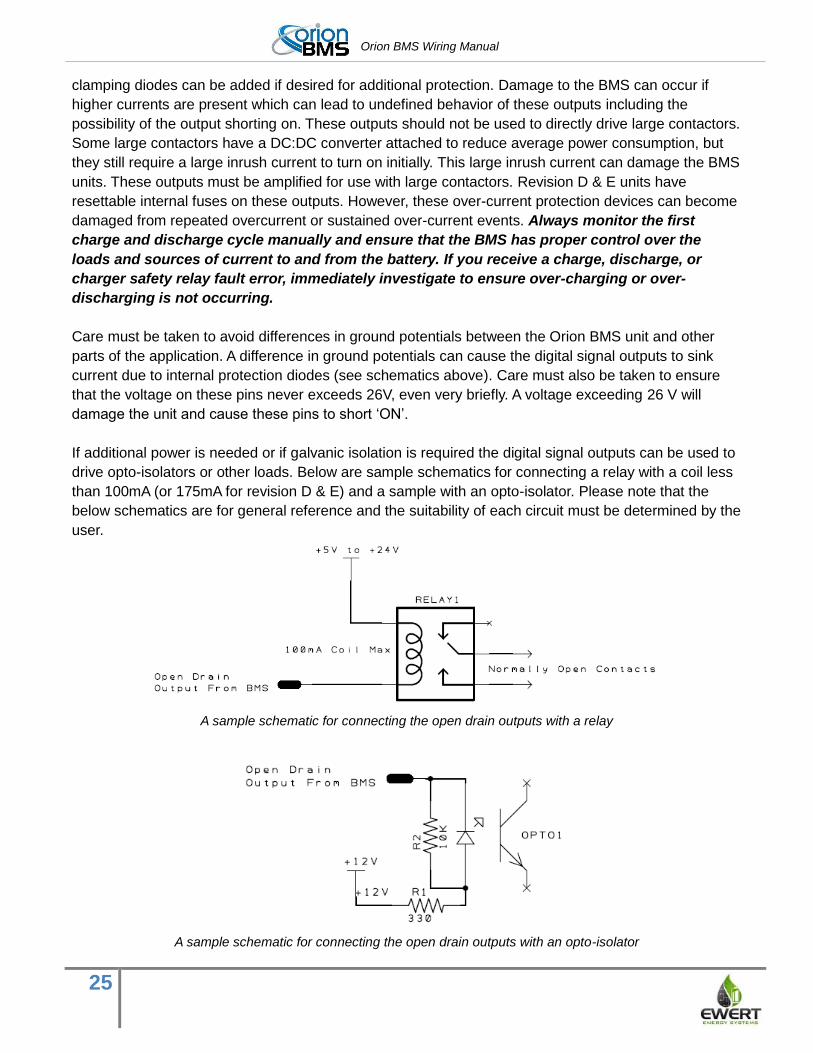
If additional power is needed or if galvanic isolation is required the digital signal outputs can be used to
drive opto-isolators or other loads. Below are sample schematics for connecting a relay with a coil less
than 100mA (or 175mA for revision D & E) and a sample with an opto-isolator. Please note that the
below schematics are for general reference and the suitability of each circuit must be determined by the
user.
A sample schematic for connecting the open drain outputs with a relay
A sample schematic for connecting the open drain outputs with an opto-isolator
Orion BMS Wiring Manual
26
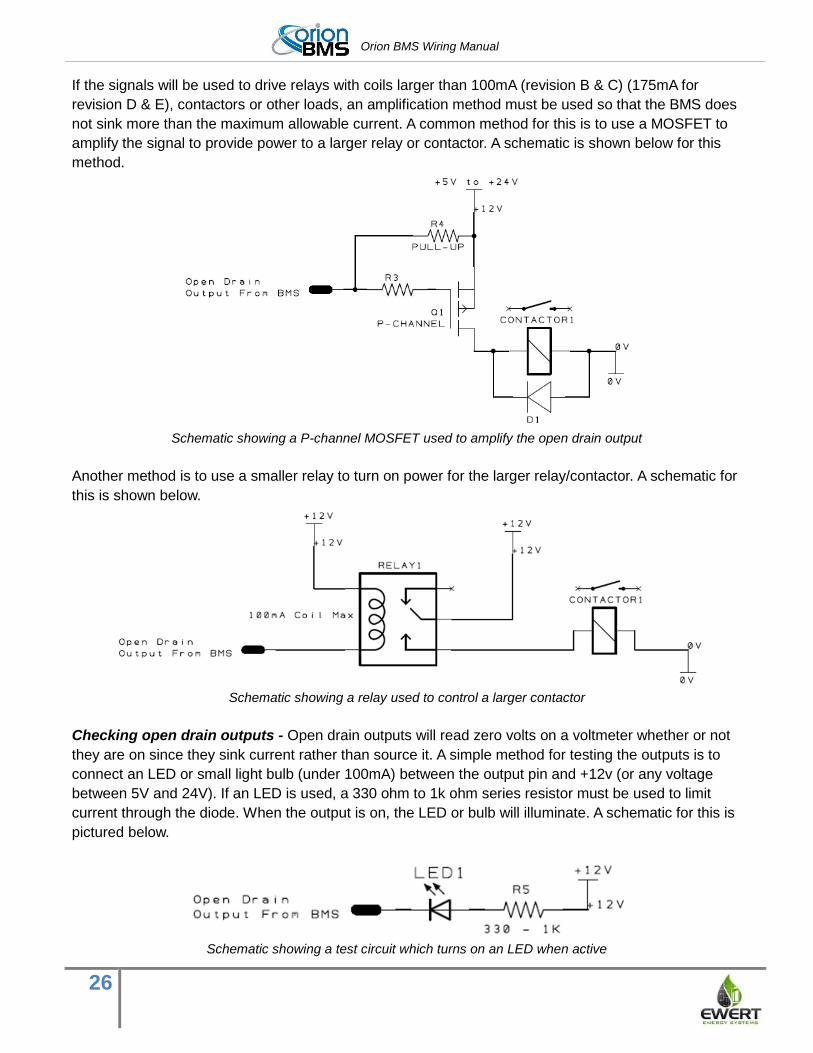
If the signals will be used to drive relays with coils larger than 100mA (revision B & C) (175mA for
revision D & E), contactors or other loads, an amplification method must be used so that the BMS does
not sink more than the maximum allowable current. A common method for this is to use a MOSFET to
amplify the signal to provide power to a larger relay or contactor. A schematic is shown below for this
method.
Schematic showing a P-channel MOSFET used to amplify the open drain output
Another method is to use a smaller relay to turn on power for the larger relay/contactor. A schematic for
this is shown below.
Schematic showing a relay used to control a larger contactor
Checking open drain outputs - Open drain outputs will read zero volts on a voltmeter whether or not
they are on since they sink current rather than source it. A simple method for testing the outputs is to
connect an LED or small light bulb (under 100mA) between the output pin and +12v (or any voltage
between 5V and 24V). If an LED is used, a 330 ohm to 1k ohm series resistor must be used to limit
current through the diode. When the output is on, the LED or bulb will illuminate. A schematic for this is
pictured below.
Schematic showing a test circuit which turns on an LED when active
Orion BMS Wiring Manual
27
Multi-purpose output (Main I/O pin 23) This output is an open drain output and is only available on hardware revision D and newer units. The
function of this output can be assigned using the setup utility. It is commonly used as an output to signal
whether an error code is present and can be used to drive an error LED, such as the LED on the Orion
BMS basic display board.
Multi-purpose input (Main I/O pin 13) This input is a nominal 12v input (it generally registers as “on” at around 5v and can withstand up to
24v). This functionality is available on firmware versions 2.5 and higher. The function of this input can
be assigned in the setup utility. It can be used to keep the BMS from going to sleep, even if the READY
power source is lost (requires always-on power to function). This pin cannot wake up the BMS. The
function of this pin can also be used to select between transmitting different CAN messages (see
software manual for more information).
Power indicator output (Main I/O pin 14)
This pin can be used to directly drive an LED to indicate whether the BMS is awake. This output is
about 1.2v lower than the input voltage when on and is current limited by an internal 1K series resistor
inside the BMS. The maximum diode current is 10mA due to the 1K resistor. The anode of an LED can
be directly connected to this pin with the cathode connected to the system ground. This output can also
be used to generate a signal for an external controller to assess whether the Orion BMS unit is awake.
Analog 0-5V outputs The Orion BMS is equipped with four analog 0 to 5V voltage outputs designed to aid in integrating the
Orion BMS with non-digital applications including voltage based displays. The outputs include pack
state of charge, amperage going in and out of the pack, charge current limit and discharge current limit.
Each of the 0-5V analog voltage outputs can provide or sink up to 10mA of current. If more current is
necessary or if a different voltage range is necessary, an external analog buffer or op-amp must be
used to amplify the signal. The analog voltages are generated inside the Orion BMS unit by a digital-to-
analog converter. Do not use these signals as the sole means to control charge or discharge as the
digital-to-analog converter is not watchdog backed, If these outputs are used to limit charge or
discharge current, always use them in conjunction with one of the charge enable, discharge enable, or
charger safety outputs.
State of charge output (Main I/O pin 4)
This output provides the calculated state of charge. 0V corresponds to 0% state of charge and 5V cor-
responds to 100% state of charge. This output often is used to display state of charge for applications
when digital communications are not available. It can also be used to provide data to the basic display
Orion BMS Wiring Manual
28
board. For information on connecting the basic display, please refer to the basic display manual, which
can be found at www.orionbms.com.
Amperage output (Main I/O pin 15)
This output provides approximate amperage in and out of the battery pack. Since this output can
display either positive or negative amperage, 2.5V corresponds to 0 amps. A voltage above 2.5V
indicates discharge where-as a voltage below 2.5V indicates charge.
The formula for converting the analog voltage to amperage is as follows:
totalAmpRange = ((sensor_size * 0.25) + sensor_size) * 2)
Amps = ((analog_voltage / 5.0) * totalAmpRange) - (totalAmpRange / 2)
sensor_size = the nominal current rating of the current sensor. This would be 200 for a 200A current
sensor or 750 for a 750A current sensor.
While this output is useful for a user display showing the rough amperage in and out of the pack,
voltage offset errors and 10 bit resolution make it difficult to use this output for precision amperage
measurements. If more precise measurements are necessary, the digital CAN information should be
used.
Charge current limit (Main I/O pin 5)
This output provides an analog representation of the maximum current that the battery can accept at
any given time. 0V corresponds to 0 amps and 5V corresponds to the maximum amperage set in the
profile for this specific output (please see the software manual for information on setting this maximum
value).
While this output can be reliably used to limit current, it should be used in conjunction with the charge
enable signal output (Main I/O pin 8) which provides an analog watchdog shutoff circuit. Although
unlikely, it is possible for the digital-to-analog converter to fail leaving the voltage in an undefined state.
Discharge current limit (Main I/O pin 16)
This output provides an analog representation of the maximum current that the battery can discharge at
any given time. 0V corresponds to 0 amps and 5V corresponds to the maximum amperage set in the
profile for this specific output (please see the software manual for information on setting this maximum
value).
While this output can be reliably used to limit current, it should be used in conjunction with the
discharge enable signal output (Main I/O pin 8) which provides an analog watchdog shutoff circuit.
Although unlikely, it is possible for the digital-to-analog converter to fail leaving the voltage in an
undefined state.
Orion BMS Wiring Manual
29
Fan controller The Orion BMS features a thermal management system consisting of thermistors for measuring battery
temperature (and optionally for measuring intake air temperature), an on/off output and PWM output
designed to control a fan and a voltage monitoring circuit designed to ensure that a fan is operating
properly.
The Orion BMS base unit supports up to four thermistors directly connected to the BMS. More than 800
additional thermistors can be connected to the Orion BMS using thermistor expansion modules. For
more information on the thermistors, please see the “Current sensor / thermistor connector” section.
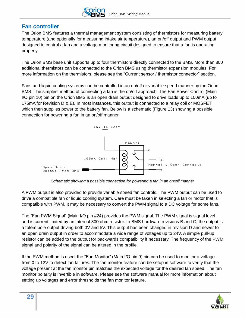
Fans and liquid cooling systems can be controlled in an on/off or variable speed manner by the Orion
BMS. The simplest method of connecting a fan is the on/off approach. The Fan Power Control (Main
I/O pin 10) pin on the Orion BMS is an open drain output designed to drive loads up to 100mA (up to
175mA for Revision D & E). In most instances, this output is connected to a relay coil or MOSFET
which then supplies power to the battery fan. Below is a schematic (Figure 13) showing a possible
connection for powering a fan in an on/off manner.
Schematic showing a possible connection for powering a fan in an on/off manner
A PWM output is also provided to provide variable speed fan controls. The PWM output can be used to
drive a compatible fan or liquid cooling system. Care must be taken in selecting a fan or motor that is
compatible with PWM. It may be necessary to convert the PWM signal to a DC voltage for some fans.
The “Fan PWM Signal” (Main I/O pin #24) provides the PWM signal. The PWM signal is signal level
and is current limited by an internal 300 ohm resistor. In BMS hardware revisions B and C, the output is
a totem pole output driving both 0V and 5V. This output has been changed in revision D and newer to
an open drain output in order to accommodate a wide range of voltages up to 24V. A simple pull-up
resistor can be added to the output for backwards compatibility if necessary. The frequency of the PWM
signal and polarity of the signal can be altered in the profile.
If the PWM method is used, the “Fan Monitor” (Main I/O pin 9) pin can be used to monitor a voltage
from 0 to 12V to detect fan failures. The fan monitor feature can be setup in software to verify that the
voltage present at the fan monitor pin matches the expected voltage for the desired fan speed. The fan
monitor polarity is invertible in software. Please see the software manual for more information about
setting up voltages and error thresholds the fan monitor feature.
Orion BMS Wiring Manual
30
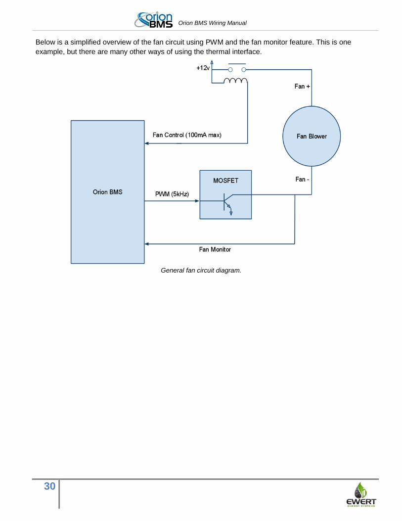
Below is a simplified overview of the fan circuit using PWM and the fan monitor feature. This is one
example, but there are many other ways of using the thermal interface.
General fan circuit diagram.
Orion BMS Wiring Manual
31
Wiring the Current Sensor / Thermistor
Connector
Wire side of Current Sensor / Thermistor Connector
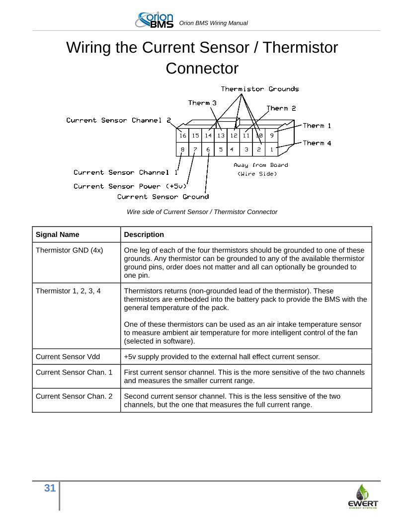
Signal Name Description
Thermistor GND (4x) One leg of each of the four thermistors should be grounded to one of these grounds. Any thermistor can be grounded to any of the available thermistor ground pins, order does not matter and all can optionally be grounded to one pin.
Thermistor 1, 2, 3, 4 Thermistors returns (non-grounded lead of the thermistor). These thermistors are embedded into the battery pack to provide the BMS with the general temperature of the pack. One of these thermistors can be used as an air intake temperature sensor to measure ambient air temperature for more intelligent control of the fan (selected in software).
Current Sensor Vdd +5v supply provided to the external hall effect current sensor.
Current Sensor Chan. 1 First current sensor channel. This is the more sensitive of the two channels and measures the smaller current range.
Current Sensor Chan. 2 Second current sensor channel. This is the less sensitive of the two channels, but the one that measures the full current range.
Orion BMS Wiring Manual
32
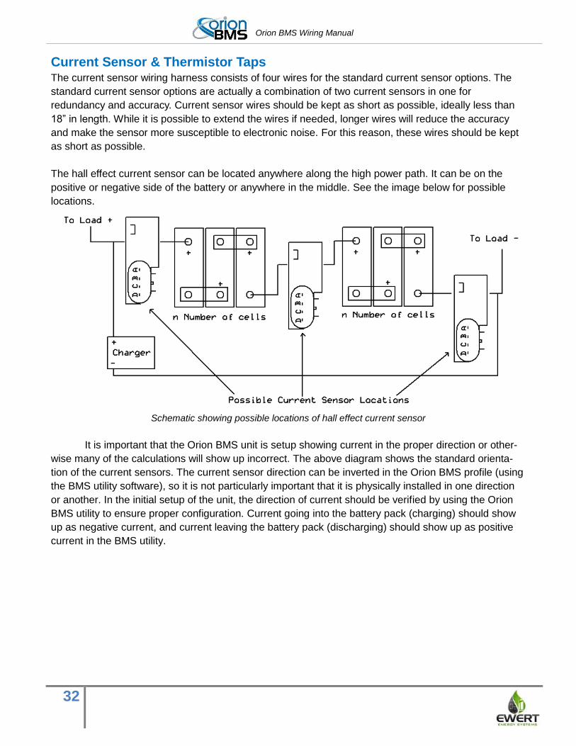
Current Sensor & Thermistor Taps The current sensor wiring harness consists of four wires for the standard current sensor options. The
standard current sensor options are actually a combination of two current sensors in one for
redundancy and accuracy. Current sensor wires should be kept as short as possible, ideally less than
18” in length. While it is possible to extend the wires if needed, longer wires will reduce the accuracy
and make the sensor more susceptible to electronic noise. For this reason, these wires should be kept
as short as possible.
The hall effect current sensor can be located anywhere along the high power path. It can be on the
positive or negative side of the battery or anywhere in the middle. See the image below for possible
locations.
Schematic showing possible locations of hall effect current sensor
It is important that the Orion BMS unit is setup showing current in the proper direction or other-
wise many of the calculations will show up incorrect. The above diagram shows the standard orienta-
tion of the current sensors. The current sensor direction can be inverted in the Orion BMS profile (using
the BMS utility software), so it is not particularly important that it is physically installed in one direction
or another. In the initial setup of the unit, the direction of current should be verified by using the Orion
BMS utility to ensure proper configuration. Current going into the battery pack (charging) should show
up as negative current, and current leaving the battery pack (discharging) should show up as positive
current in the BMS utility.
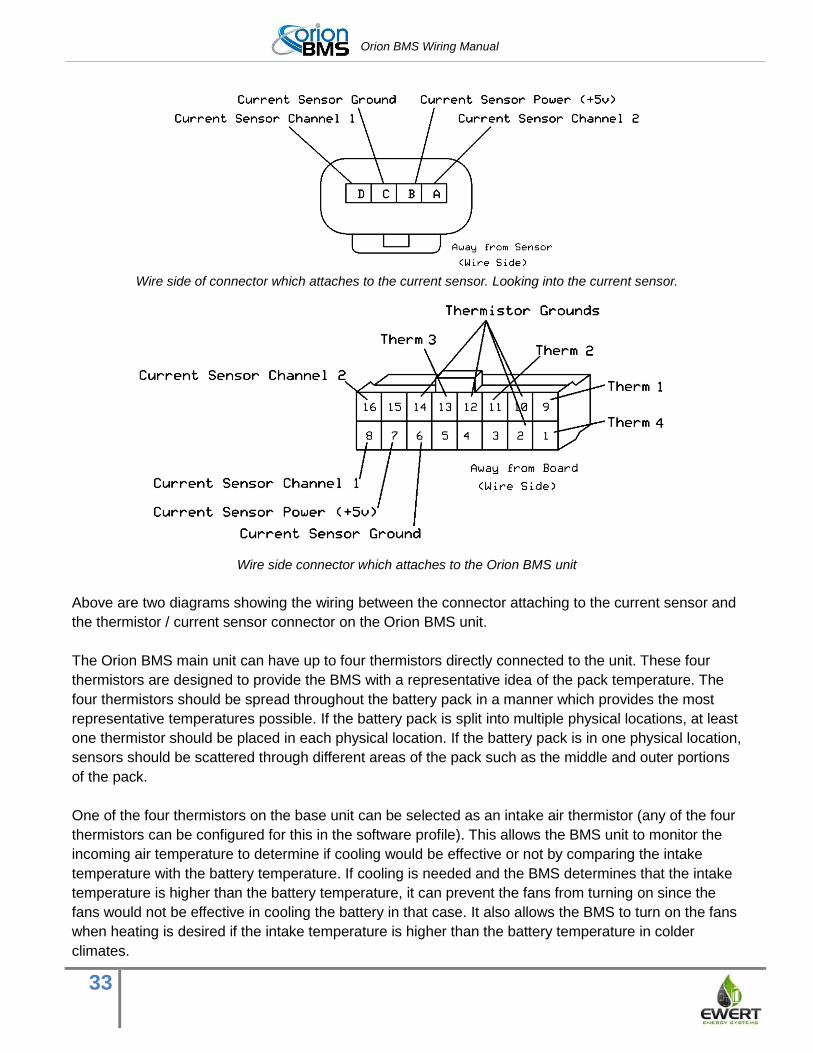
Orion BMS Wiring Manual
33
Wire side of connector which attaches to the current sensor. Looking into the current sensor.
Wire side connector which attaches to the Orion BMS unit
Above are two diagrams showing the wiring between the connector attaching to the current sensor and
the thermistor / current sensor connector on the Orion BMS unit.
The Orion BMS main unit can have up to four thermistors directly connected to the unit. These four
thermistors are designed to provide the BMS with a representative idea of the pack temperature. The
four thermistors should be spread throughout the battery pack in a manner which provides the most
representative temperatures possible. If the battery pack is split into multiple physical locations, at least
one thermistor should be placed in each physical location. If the battery pack is in one physical location,
sensors should be scattered through different areas of the pack such as the middle and outer portions
of the pack.
One of the four thermistors on the base unit can be selected as an intake air thermistor (any of the four
thermistors can be configured for this in the software profile). This allows the BMS unit to monitor the
incoming air temperature to determine if cooling would be effective or not by comparing the intake
temperature with the battery temperature. If cooling is needed and the BMS determines that the intake
temperature is higher than the battery temperature, it can prevent the fans from turning on since the
fans would not be effective in cooling the battery in that case. It also allows the BMS to turn on the fans
when heating is desired if the intake temperature is higher than the battery temperature in colder
climates.

Orion BMS Wiring Manual
34
If monitoring more than four temperatures is necessary, an external thermistor expansion module is
available which can monitor up to eighty additional thermistors per module with up to ten modules
connected (up to 804 thermistors total), which should be sufficient for most applications. If the external
thermistor expansion module is used, it is recommended to still connect as many thermistors to the
main Orion BMS unit as possible so that the unit can still sense temperatures even if there is a fault
with the thermistor expansion module.
The thermistors are 10K NTC thermistors with a B25/50 value of 3380K. Other B values can be used,
though the accuracy will be reduced. Custom configurations for B values may be available for high
volume applications requiring a different B value. One end of the thermistor is connected to the
appropriate thermistor pin and the other is grounded to one of the thermistor ground pins. As
thermistors are resistive, polarity does not matter and the order of thermistor ground pins does not
matter. All thermistor common wires can be connected to a single thermistor ground pin if helpful for
cable routing.
Thermistors can be attached to the battery cells in different ways depending on the type of cell. The
thermistors sold with the Orion BMS have epoxy coated beads at the ends. They can be taped or glued
to cells. Other thermistors (sourced separately) are attached to ring terminals and can be installed onto
battery terminals. Care must be taken to ensure that thermistors are sufficiently electrically
isolated from the battery pack. The thermistor measurement pins are NOT electrically isolated
from any other pin on the Thermistor or Main I/O connectors, and a breakdown in isolation may
cause a short! The integrator is responsible for ensuring proper isolation and any necessary fusing for
protection against shorts. Insufficient isolation can cause shorts outside the BMS and/or catastrophic
damage to the BMS unit. Fuses to guard against shorts on the thermistors may be necessary in some
applications.

Orion BMS Wiring Manual
35
Wiring the Pack Voltage Sensor Connector
Wire side of pack voltage sensor connector
NOTE: Follow the above diagram instead of the pin numbers listed on the connector.
Signal Name Description
Pack Negative Negative pack voltage sensor. This should be connected to the negative output from the battery pack. This connection is used to monitor for breakdowns in isolation between the 12V ground and the battery pack negative. If not connected, the BMS cannot measure for isolation breakdown.
Pack Positive Positive pack voltage sensor. This should be connected to the positive output from the battery pack.
Both the negative and positive pack voltage sensors are used to redundantly monitor the total pack
voltage and monitor for isolation faults.
HV Pack Voltage Sense Connector The pack voltage sensor consists simply of one wire going to the total pack negative and the other to
the total pack positive. This connector is used for redundant voltage monitoring for error detection as
well as for isolation fault detection. These wires should be connected as close to the battery terminals
as possible to avoid voltage drop. The BMS must always be able to read a pack voltage while
operating; otherwise an error will be set.
This total pack voltage sensing connection is optional for BMS unit with firmware revisions 2.6.8 and
newer. If firmware 2.6.8 or newer is used, this connector may be left disconnected. The negative pack
wire must still be connected to the negative-most terminal in the battery pack if isolation fault detection
is to be used. Leaving both the pack positive and pack negative wires disconnected will prohibit the
isolation fault detection circuit from working.
If multiple Orion BMS units are being used in series, the total pack voltage sensor connection
should be connected only to the portion of the pack that the BMS is controlling.
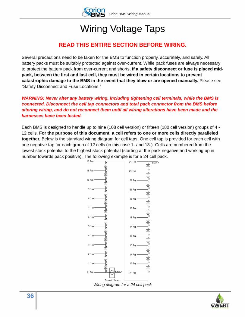
Orion BMS Wiring Manual
36
Wiring Voltage Taps
READ THIS ENTIRE SECTION BEFORE WIRING.
Several precautions need to be taken for the BMS to function properly, accurately, and safely. All
battery packs must be suitably protected against over-current. While pack fuses are always necessary
to protect the battery pack from over-current and shorts, if a safety disconnect or fuse is placed mid-
pack, between the first and last cell, they must be wired in certain locations to prevent
catastrophic damage to the BMS in the event that they blow or are opened manually. Please see
“Safety Disconnect and Fuse Locations.”
WARNING: Never alter any battery wiring, including tightening cell terminals, while the BMS is
connected. Disconnect the cell tap connectors and total pack connector from the BMS before
altering wiring, and do not reconnect them until all wiring alterations have been made and the
harnesses have been tested.
Each BMS is designed to handle up to nine (108 cell version) or fifteen (180 cell version) groups of 4 -
12 cells. For the purpose of this document, a cell refers to one or more cells directly paralleled
together. Below is the standard wiring diagram for cell taps. One cell tap is provided for each cell with
one negative tap for each group of 12 cells (in this case 1- and 13-). Cells are numbered from the
lowest stack potential to the highest stack potential (starting at the pack negative and working up in
number towards pack positive). The following example is for a 24 cell pack.
Wiring diagram for a 24 cell pack
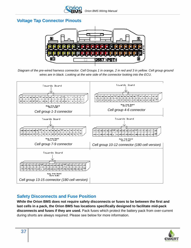
Orion BMS Wiring Manual
37
Voltage Tap Connector Pinouts
Diagram of the pre-wired harness connector. Cell Groups 1 in orange, 2 in red and 3 in yellow. Cell group ground
wires are in black. Looking at the wire side of the connector looking into the ECU.
Cell group 1-3 connector
Cell group 4-6 connector
Cell group 7-9 connector
Cell group 10-12 connector (180 cell version)
Cell group 13-15 connector (180 cell version)
Safety Disconnects and Fuse Position While the Orion BMS does not require safety disconnects or fuses to be between the first and
last cells in a pack, the Orion BMS has locations specifically designed to facilitate mid-pack
disconnects and fuses if they are used. Pack fuses which protect the battery pack from over-current
during shorts are always required. Please see below for more information.
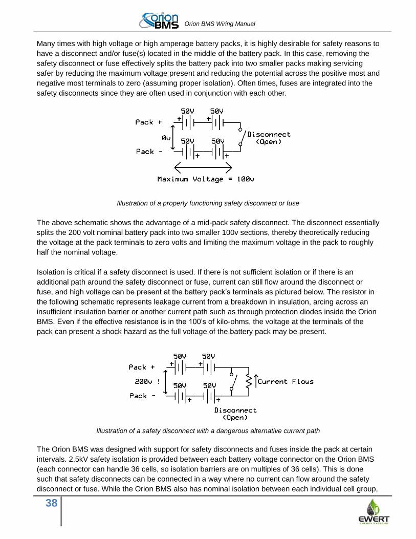
Orion BMS Wiring Manual
38
Many times with high voltage or high amperage battery packs, it is highly desirable for safety reasons to
have a disconnect and/or fuse(s) located in the middle of the battery pack. In this case, removing the
safety disconnect or fuse effectively splits the battery pack into two smaller packs making servicing
safer by reducing the maximum voltage present and reducing the potential across the positive most and
negative most terminals to zero (assuming proper isolation). Often times, fuses are integrated into the
safety disconnects since they are often used in conjunction with each other.
Illustration of a properly functioning safety disconnect or fuse
The above schematic shows the advantage of a mid-pack safety disconnect. The disconnect essentially
splits the 200 volt nominal battery pack into two smaller 100v sections, thereby theoretically reducing
the voltage at the pack terminals to zero volts and limiting the maximum voltage in the pack to roughly
half the nominal voltage.
Isolation is critical if a safety disconnect is used. If there is not sufficient isolation or if there is an
additional path around the safety disconnect or fuse, current can still flow around the disconnect or
fuse, and high voltage can be present at the battery pack’s terminals as pictured below. The resistor in
the following schematic represents leakage current from a breakdown in insulation, arcing across an
insufficient insulation barrier or another current path such as through protection diodes inside the Orion
BMS. Even if the effective resistance is in the 100’s of kilo-ohms, the voltage at the terminals of the
pack can present a shock hazard as the full voltage of the battery pack may be present.
Illustration of a safety disconnect with a dangerous alternative current path
The Orion BMS was designed with support for safety disconnects and fuses inside the pack at certain
intervals. 2.5kV safety isolation is provided between each battery voltage connector on the Orion BMS
(each connector can handle 36 cells, so isolation barriers are on multiples of 36 cells). This is done
such that safety disconnects can be connected in a way where no current can flow around the safety
disconnect or fuse. While the Orion BMS also has nominal isolation between each individual cell group,
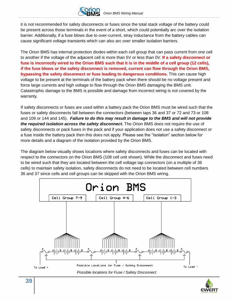
Orion BMS Wiring Manual
39
it is not recommended for safety disconnects or fuses since the total stack voltage of the battery could
be present across those terminals in the event of a short, which could potentially arc over the isolation
barrier. Additionally, if a fuse blows due to over-current, stray inductance from the battery cables can
cause significant voltage transients which can also arc over smaller isolation barriers.
The Orion BMS has internal protection diodes within each cell group that can pass current from one cell
to another if the voltage of the adjacent cell is more than 5V or less than 0V. If a safety disconnect or
fuse is incorrectly wired to the Orion BMS such that it is in the middle of a cell group (12 cells),
if the fuse blows or the safety disconnect is removed, current can flow through the Orion BMS,
bypassing the safety disconnect or fuse leading to dangerous conditions. This can cause high
voltage to be present at the terminals of the battery pack when there should be no voltage present and
force large currents and high voltage to flow through the Orion BMS damaging the BMS unit.
Catastrophic damage to the BMS is possible and damage from incorrect wiring is not covered by the
warranty.
If safety disconnects or fuses are used within a battery pack the Orion BMS must be wired such that the
fuses or safety disconnects fall between the connectors (between taps 36 and 37 or 72 and 73 or 108
and 109 or 144 and 145). Failure to do this may result in damage to the BMS and will not provide
the required isolation across the safety disconnect. The Orion BMS does not require the use of
safety disconnects or pack fuses in the pack and if your application does not use a safety disconnect or
a fuse inside the battery pack then this does not apply. Please see the “Isolation” section below for
more details and a diagram of the isolation provided by the Orion BMS.
The diagram below visually shows locations where safety disconnects and fuses can be located with
respect to the connectors on the Orion BMS (108 cell unit shown). While the disconnect and fuses need
to be wired such that they are located between the cell voltage tap connectors (on a multiple of 36
cells) to maintain safety isolation, safety disconnects do not need to be located between cell numbers
36 and 37 since cells and cell groups can be skipped with the Orion BMS wiring.
Possible locations for Fuse / Safety Disconnect
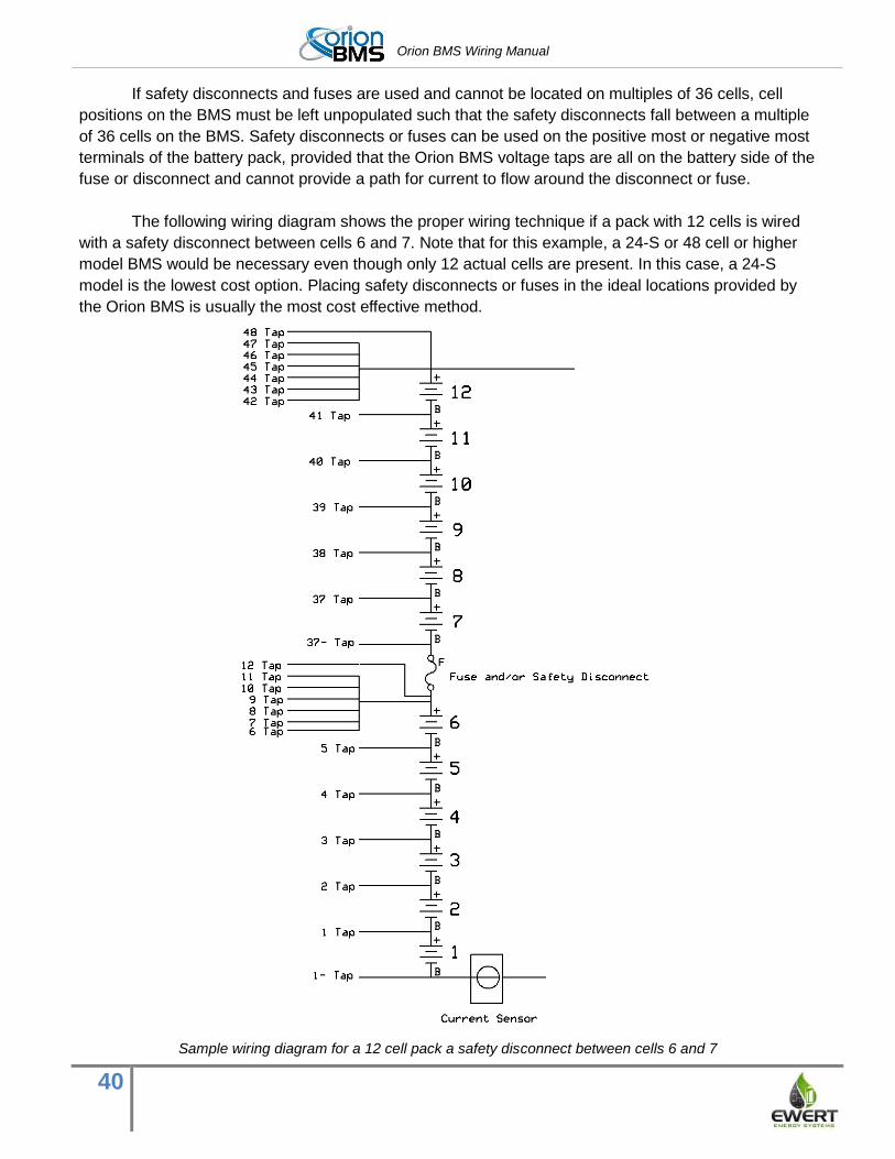
Orion BMS Wiring Manual
40
If safety disconnects and fuses are used and cannot be located on multiples of 36 cells, cell
positions on the BMS must be left unpopulated such that the safety disconnects fall between a multiple
of 36 cells on the BMS. Safety disconnects or fuses can be used on the positive most or negative most
terminals of the battery pack, provided that the Orion BMS voltage taps are all on the battery side of the
fuse or disconnect and cannot provide a path for current to flow around the disconnect or fuse.
The following wiring diagram shows the proper wiring technique if a pack with 12 cells is wired
with a safety disconnect between cells 6 and 7. Note that for this example, a 24-S or 48 cell or higher
model BMS would be necessary even though only 12 actual cells are present. In this case, a 24-S
model is the lowest cost option. Placing safety disconnects or fuses in the ideal locations provided by
the Orion BMS is usually the most cost effective method.
Sample wiring diagram for a 12 cell pack a safety disconnect between cells 6 and 7
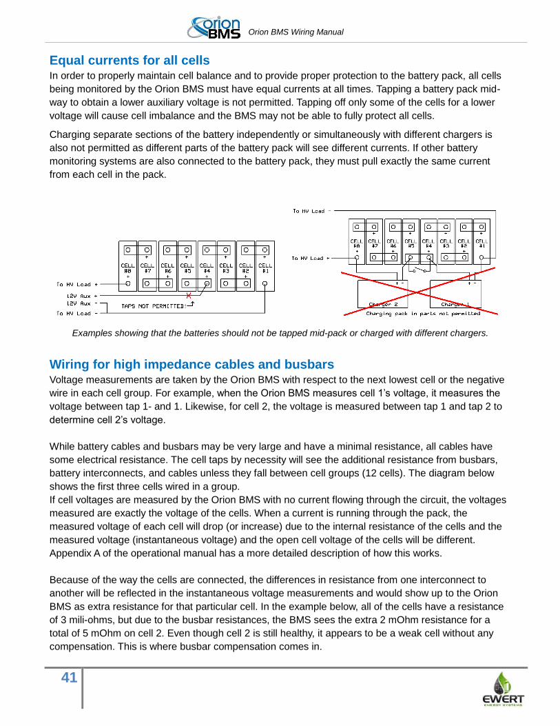
Orion BMS Wiring Manual
41
Equal currents for all cells In order to properly maintain cell balance and to provide proper protection to the battery pack, all cells
being monitored by the Orion BMS must have equal currents at all times. Tapping a battery pack mid-
way to obtain a lower auxiliary voltage is not permitted. Tapping off only some of the cells for a lower
voltage will cause cell imbalance and the BMS may not be able to fully protect all cells.
Charging separate sections of the battery independently or simultaneously with different chargers is
also not permitted as different parts of the battery pack will see different currents. If other battery
monitoring systems are also connected to the battery pack, they must pull exactly the same current
from each cell in the pack.
Examples showing that the batteries should not be tapped mid-pack or charged with different chargers.
Wiring for high impedance cables and busbars Voltage measurements are taken by the Orion BMS with respect to the next lowest cell or the negative
wire in each cell group. For example, when the Orion BMS measures cell 1’s voltage, it measures the
voltage between tap 1- and 1. Likewise, for cell 2, the voltage is measured between tap 1 and tap 2 to
determine cell 2’s voltage.
While battery cables and busbars may be very large and have a minimal resistance, all cables have
some electrical resistance. The cell taps by necessity will see the additional resistance from busbars,
battery interconnects, and cables unless they fall between cell groups (12 cells). The diagram below
shows the first three cells wired in a group.
If cell voltages are measured by the Orion BMS with no current flowing through the circuit, the voltages
measured are exactly the voltage of the cells. When a current is running through the pack, the
measured voltage of each cell will drop (or increase) due to the internal resistance of the cells and the
measured voltage (instantaneous voltage) and the open cell voltage of the cells will be different.
Appendix A of the operational manual has a more detailed description of how this works.
Because of the way the cells are connected, the differences in resistance from one interconnect to
another will be reflected in the instantaneous voltage measurements and would show up to the Orion
BMS as extra resistance for that particular cell. In the example below, all of the cells have a resistance
of 3 mili-ohms, but due to the busbar resistances, the BMS sees the extra 2 mOhm resistance for a
total of 5 mOhm on cell 2. Even though cell 2 is still healthy, it appears to be a weak cell without any
compensation. This is where busbar compensation comes in.
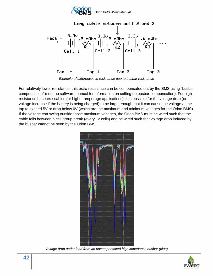
Orion BMS Wiring Manual
42
Example of differences in resistance due to busbar resistance
For relatively lower resistance, this extra resistance can be compensated out by the BMS using “busbar
compensation” (see the software manual for information on setting up busbar compensation). For high
resistance busbars / cables (or higher amperage applications), it is possible for the voltage drop (or
voltage increase if the battery is being charged) to be large enough that it can cause the voltage at the
tap to exceed 5V or drop below 0V (which are the maximum and minimum voltages for the Orion BMS).
If the voltage can swing outside those maximum voltages, the Orion BMS must be wired such that the
cable falls between a cell group break (every 12 cells) and be wired such that voltage drop induced by
the busbar cannot be seen by the Orion BMS.
Voltage drop under load from an uncompensated high impedance busbar (blue)
Orion BMS Wiring Manual
43
Maximum voltage swing can be calculated if the maximum cell voltage, resistance of the busbar / cable
and maximum amperage are known using the following formulas. Please keep in mind that the
resistance of the busbar or cable must include the resistance of the terminal and any crimps. Headroom
must be left for possible small increases in resistance due to eventual corrosion, etc.
Peak_voltage = Vmax_cell + (Rbusbar * Imax_charge) (Peak_voltage must be < 5v)
Lowest_voltage = Vmin_cell - (Rbusbar * Imax_discharge) (Lowest voltage must be >0v)
In the above example, if the example cells have a maximum voltage of 3.65v (Vmax_cell) and a
minimum of 2v (Vmin_cell) and a maximum amperage of +/-200A (Imax_charge and Imax_discharge),
the peak voltage with the given 2 mOhm cable would be 4.05v and the lowest voltage 1.6v. These
voltages are within the limits and busbar compensation could be used.
Skin effect issues due to AC currents The vast majority of motor controllers available on the market provide some amount of filtering on the
DC bus in order to limit radiated and conducted emissions. While most motor controllers generate high
levels of noise, the noise generally does not lead to a significant AC component on the DC bus. A small
minority of motor controllers lack adequate internal bulk capacitance and filtering and actually produce
a high frequency AC component on the DC bus.
The Orion BMS is extremely resistant to electrical noise (EMI) and has been tested in real world
situations to operate successfully with this excessive noise. However, a strong high frequency AC
component can create a “Skin Effect” on the cables connecting the batteries. Skin effect is where eddy
currents form within the cables and effectively cause only the outside portion of the wire carries current,
effectively increasing the resistance of the wire.
Although the Orion BMS has been tested extensively to operate and measure voltages properly in
these extremely harsh noise environments, the BMS may correctly measure unpredictably changing
resistance values since the effective resistance of the cable is changing considerably with respect to
amplitude and frequency. The Orion BMS bases many calculations on the measured resistance of the
cells, including open cell voltage calculations which are used for determining maximum current limits
and determine when cells are weak. If a significant skin effect is present, it can introduce inaccuracies
with some calculations even though the Orion BMS continues to operate.
The overwhelming majority of motor controllers have adequate filtering to reduce conducted emissions
to levels that prevent a skin effect from forming. For the small number that do not, the skin effect can be
mitigated somewhat by using suitable rectangular busbars or straps rather than round cables. In an
environment where a skin effect forms, any round cables should be wired such that they fall between a
cell groups since the BMS cannot effectively compensate them out. Additionally, it may be possible to
add external filtering to the motor controller to suppress the conducted emissions generated by the
motor controller to a tolerable level. Extremely high amounts of AC noise can also cause back EMF
from stray inductance in the cabling. If this occurs, the emissions will need to be limited to a safe level.
Orion BMS Wiring Manual
44
Transients Transients on the battery pack must be limited to reasonable levels. This is important both for the
protection of the BMS as well as the protection of the attached lithium cells. Lithium cells exposed to
extreme transients may short and enter thermal runaway. Extreme transients are often generated by
the combination of rapid changes in current and stray inductance. These usually occur when bulk
capacitors in motor controllers or chargers are switched into circuit or by other rapid changes in current
such as from a blowing fuse or sudden connection of current. Transients from normal switching from
contactors can be limited by using proper pre-charge circuits and limiting slew rates for motor
controllers. The use of multiple chargers with series diodes is not recommended for use with the Orion
BMS as these configurations can cause damaging transients.
Excessive transients may cause damage to the Orion BMS unit or to connected lithium ion cells. In the
event of excessive transients, the Orion BMS unit and lithium cells should be inspected or tested for
damage as damage can lead to safety risks.
All versions of the Orion BMS have protection against moderate transients on the high voltage
measurement circuits. Hardware revisions B, C & D have TVS diodes and internal fuses to protect
against transients. Severe transients may cause the internal fuses to blow and transients > 30 volts on
one cell may cause more significant damage that requires the unit to be returned for service. Damage
to the BMS unit may also occur if the total group voltage exceeds 80V (>6.5v on all cell inputs).
Hardware revision E has a wider survivable voltage range and can therefore survive larger transients,
but transients still must be limited for the safety of the lithium cells, and repeated exposure to
excessively large transients may eventually damage the BMS,
If a unit has been damaged by transients, it must be disconnected immediately from service and
repaired or replaced. Never continue to use a damaged unit.
Wiring Errors Wiring errors can cause serious damage to the Orion BMS that is not covered under warranty. All
revisions of the Orion BMS have internal fuses on each cell tap wire to protect the BMS and connected
wiring from excessive currents. The BMS units also have protection diodes which on revision B, C & D
are designed to cause the internal fuses to blow when voltage measured between any two cells is less
than 0v or greater than 5v. When this happens, the BMS may report an “open wire fault” or “wiring
fault”. These fault codes can also indicate a wire that is simply not connected to a cell or loosely
connected to a cell.
Revision E units have been upgraded to withstand certain minor wiring errors such as accidentally
swapping the order of two cells or even wiring cells in the reverse order. The internal fuses are
designed to blow with voltages more than +/- 24v (though there are some rare situations where fuses
can still blow at lower voltages and some situations where they won’t blow until voltages are higher.
Revision E units can withstand wiring errors only for a short period of time and repeated exposure to
wiring errors or extended wiring errors may cause permanent damage. If revision E units are wired
improperly, small currents may flow through the BMS. An incorrectly wired unit should not be
left connected to the battery pack for more than 5 minutes as it will eventually drain and can
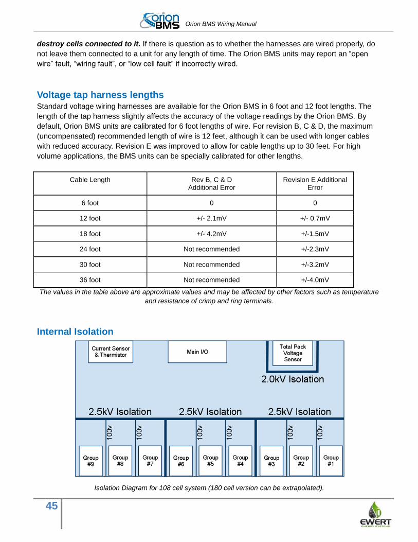
Orion BMS Wiring Manual
45
destroy cells connected to it. If there is question as to whether the harnesses are wired properly, do
not leave them connected to a unit for any length of time. The Orion BMS units may report an “open
wire” fault, “wiring fault”, or “low cell fault” if incorrectly wired.
Voltage tap harness lengths Standard voltage wiring harnesses are available for the Orion BMS in 6 foot and 12 foot lengths. The
length of the tap harness slightly affects the accuracy of the voltage readings by the Orion BMS. By
default, Orion BMS units are calibrated for 6 foot lengths of wire. For revision B, C & D, the maximum
(uncompensated) recommended length of wire is 12 feet, although it can be used with longer cables
with reduced accuracy. Revision E was improved to allow for cable lengths up to 30 feet. For high
volume applications, the BMS units can be specially calibrated for other lengths.
Cable Length Rev B, C & D Additional Error
Revision E Additional Error
6 foot 0 0
12 foot +/- 2.1mV +/- 0.7mV
18 foot +/- 4.2mV +/-1.5mV
24 foot Not recommended +/-2.3mV
30 foot Not recommended +/-3.2mV
36 foot Not recommended +/-4.0mV
The values in the table above are approximate values and may be affected by other factors such as temperature
and resistance of crimp and ring terminals.
Internal Isolation
Isolation Diagram for 108 cell system (180 cell version can be extrapolated).

Orion BMS Wiring Manual
46
The Orion BMS provides 2.5kV isolation between cell voltage taps and control electronics as well as
between groups of 36 cells. The total pack voltage sensor is isolated from all other electronics by 2.0kV
DC isolation. Isolation between cell groups 1, 2 and 3 is a nominal 100v isolation which is an ideal
placement of high resistance busbars or cables between cells, but cannot be used for a safety
disconnect or fuse since it is not rated to withstand the full stack voltage.
Note that units configured with less than 108 cells do not have all nine groups populated. For 120 - 180
cell units, the same pattern of isolation continues with groups #10, 11, 12, 13, 14 and 15 with 2.5kV
isolation between groups 9 and 10 and 12 and 13.
Please note that the CAN transceivers inside the BMS are referenced to the 12v ground (Main I/O pin
12) and are not electrically isolated from each other. While most motor controllers and chargers isolate
the CANBUS from the battery pack, if the BMS is used with a motor controller, charger, or other device
which does not have an isolated CANBUS interface, an appropriately rated CANBUS isolation device
must be used.
Cell Groups with fewer than 12 cells Each cell group must have a minimum of 4 cells and up to 12 cells, with a minimum voltage of 13V per
group. If fewer than 12 cells are used, each wire must still be connected to maintain proper operation
and accuracy.
Rules for fewer than 12 cells
● If fewer than 12 cells are populated in a group, unpopulated cells must all be connected to the
highest potential cell in that group. For example, if 6 cells are populated in a group, taps 6 - 12 are all
connected to the positive tap on cell 6.*
● No cell group may have fewer than 4 cells connected (higher minimums may apply if nominal voltage
is lower than standard li-ion cells). If the last group of cells has fewer than 4 cells, some cells must
be skipped in the previous group and wired into the last group to ensure that a minimum of 4 cells
are present in the last group.
● Cell Groups must have a minimum normal working voltage of 10 volts (2.5v per cell for 4 cells) and
an absolute minimum voltage of 8V. Accuracy of voltage measurements is decreased when the
group voltage is below 10 volts.
*In this example, cell tap positions 6-11 could be combined into a single wire that runs to the terminal to
reduce the number of wires entering the battery area. However, for revision A, B, C and D units, the
12th cell tap should run directly to the highest potential cell using a separate wire to avoid an
approximately 5-7mV error in measurement on the last cell in the group. This is also recommended for
revision E when used with tap wires longer than 6ft. In all cases, the simplest approach is to run all
wires to the terminal.
Example: A battery pack of 78 cells is divided into three sections with a fuse and a long, high
impedance cable located between cells 23 / 24 and 51 / 52. 23 cells are in the first section, 28 in the
2nd section and 27 in the third section.
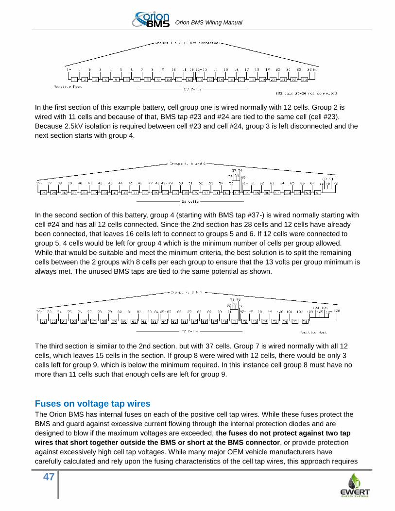
Orion BMS Wiring Manual
47
In the first section of this example battery, cell group one is wired normally with 12 cells. Group 2 is
wired with 11 cells and because of that, BMS tap #23 and #24 are tied to the same cell (cell #23).
Because 2.5kV isolation is required between cell #23 and cell #24, group 3 is left disconnected and the
next section starts with group 4.
In the second section of this battery, group 4 (starting with BMS tap #37-) is wired normally starting with
cell #24 and has all 12 cells connected. Since the 2nd section has 28 cells and 12 cells have already
been connected, that leaves 16 cells left to connect to groups 5 and 6. If 12 cells were connected to
group 5, 4 cells would be left for group 4 which is the minimum number of cells per group allowed.
While that would be suitable and meet the minimum criteria, the best solution is to split the remaining
cells between the 2 groups with 8 cells per each group to ensure that the 13 volts per group minimum is
always met. The unused BMS taps are tied to the same potential as shown.
The third section is similar to the 2nd section, but with 37 cells. Group 7 is wired normally with all 12
cells, which leaves 15 cells in the section. If group 8 were wired with 12 cells, there would be only 3
cells left for group 9, which is below the minimum required. In this instance cell group 8 must have no
more than 11 cells such that enough cells are left for group 9.
Fuses on voltage tap wires The Orion BMS has internal fuses on each of the positive cell tap wires. While these fuses protect the
BMS and guard against excessive current flowing through the internal protection diodes and are
designed to blow if the maximum voltages are exceeded, the fuses do not protect against two tap
wires that short together outside the BMS or short at the BMS connector, or provide protection
against excessively high cell tap voltages. While many major OEM vehicle manufacturers have
carefully calculated and rely upon the fusing characteristics of the cell tap wires, this approach requires
Orion BMS Wiring Manual
48
engineering work by a qualified electrical engineer and extensive testing and is never appropriate for
cells incapable of producing large enough currents to fuse wire. Fuses on cell taps are recommended
as the above technique requires must testing and engineers. Some applications will require the use
of fuses on the cell taps, and it is the sole responsibility of the integrator to determine of these
external fuses are needed. It is the sole responsibility of the integrator to research and comply
with all applicable laws, regulations, standards, and codes for the specific application.
If external cell tap fuses are used, they should be as close to the cell terminals as possible, kept as low
resistance as possible within reason, and be rated no larger than 5A. Fuses must always be rated for
the maximum possible DC working voltage with a suitable DC interrupting current rating for the
application. Certain electrical codes or regulations may dictate the maximum fuse size, and it may be
smaller than 5A depending on wire gauge and other considerations. Fuses should be selected to have
the lowest possible resistance to prevent degrading the cell voltage measurement accuracy. Series
resistors are not permitted as current limiting devices for cell tap wires as they may over-heat or limit
necessary current to blow internal fuses on the BMS.
Note: The fuses inside the BMS unit are designed to blow only in the event of over-voltage or reverse
voltage on adjacent cell taps (see “Why Fuses Blow” below for more information). Adding external fuses
to the cell taps will not prevent the fuses inside the BMS from blowing in the event of an over-voltage
situation, and if an external fuse blows due to over-voltage, the BMS must still be inspected for damage
by a factory authorized repair center.
Additionally, fuses may be necessary on thermistors to protect against a possible short between a
thermistor and a terminal of a battery. It is the sole responsibility of the integrator to determine if fuses
are necessary on the cell tap wires.
Verifying Cell Voltage Tap Wiring The wiring must be verified prior to connecting any of the wiring harnesses to the Orion BMS. Improper
wiring can cause damage to the BMS unit, catastrophic failure or even personal safety risks depending
on the extent of the wiring mistake.
The most important connectors to verify are wired correctly are the cell voltage tap harnesses. There
are two methods for doing this.
The first is the tap validation tool which is available for rental or purchase. The tool can be connected to
the wiring harness already connected to the battery pack and will verify that cells are wired in the
correct order and can detect most wiring mistakes. The verification tool is designed to withstand
incorrectly wired harnesses without damage. It is strongly recommended to use the verification tool
before plugging the harness into the Orion BMS since it is very easy to make an error wiring the
harness and it may not be obvious. Mis-wired voltage tap harnesses can cause significant
damage to the Orion BMS that is not covered under warranty. Please refer to the cell tap validation
tool manual for more information on proper testing.
Orion BMS Wiring Manual
49
Wiring can also be verified by carefully using a multimeter (the use of the tap validation tool is the
recommended method). Care must be taken not to short any pins with the multimeter given the
size of the connector pins. Personal safety equipment including protective eye-wear and gloves
and arc-flash resistant clothing should be worn for protection in the event of an arc flash. In
order to avoid two probes on the connector, the negative probe should be attached to the negative-
most terminal of the negative-most cell in the pack rather than on the connector. Then, being careful not
to short pins or touch the probe, carefully measure each of the pins on the connector starting with the
pin for 1-. On the first connector, the 1- pin should read 0V since the negative probe of the multimeter
should be connected to the same cell. Pin 1+ should read the voltage of the first cell (3.3V for
example); pin 2 should read the sum of the first two cells (6.6V for example) and so forth. The
connection for cell 12 and 13- should read the same voltage since they are connected to the same
potential and the same is true for every multiple of 12.
When connecting the harness to the BMS for the first time, (after first verifying correct wiring), first
adjust the cell population settings in the BMS software so the BMS is aware which cells it should be
expecting to see. Once you have uploaded the profile to the BMS (see the software manual for more
information on this), use the live cell voltages screen to verify that all cell voltages are reading correctly.
Then verify on the diagnostic trouble code screen that no “open wire faults” or “wiring faults” (and “low
cell” faults for revision E) are present on the BMS. Open wire or wiring faults indicate that the BMS has
detected a problem with the cell tap wiring. If errors are found or if cell voltages are not matching
properly, do not leave the BMS connected to the pack for long periods of time as it may drain
cells and cause damage to them.
Disconnect Cell Taps While Altering Battery Wiring Any time battery wiring is altered in any way, the cell taps on the Orion BMS MUST be fully
disconnected from the BMS.
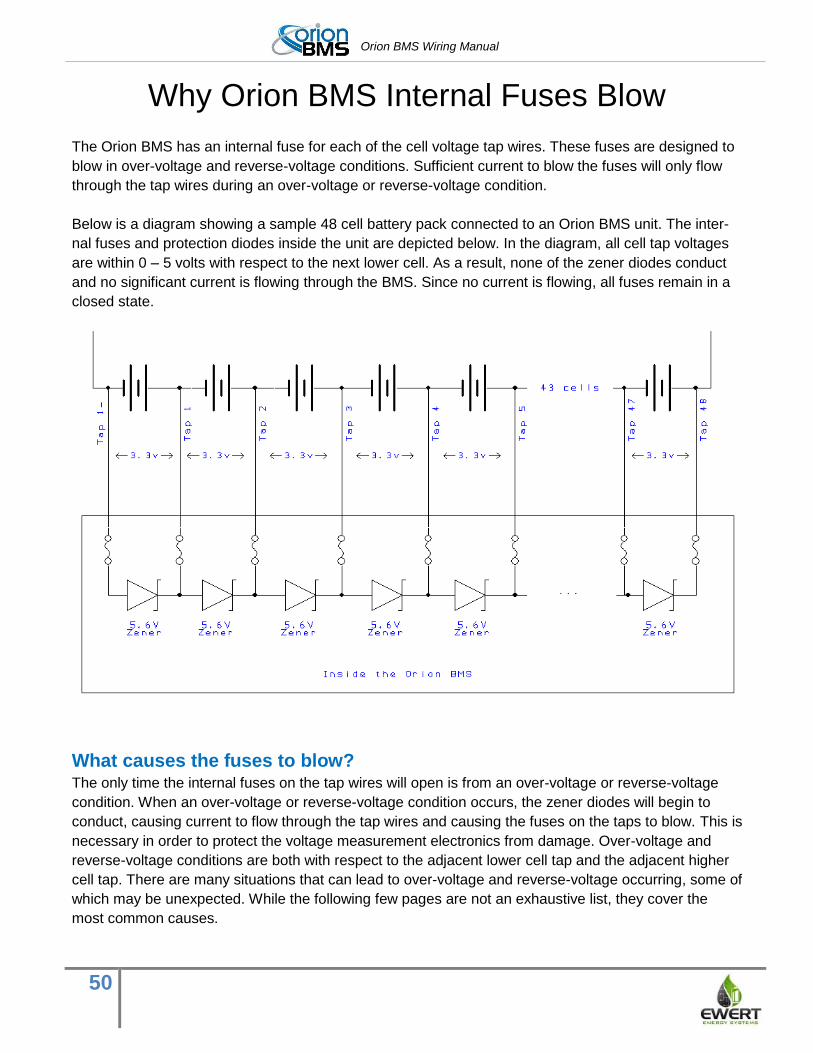
Orion BMS Wiring Manual
50
Why Orion BMS Internal Fuses Blow
The Orion BMS has an internal fuse for each of the cell voltage tap wires. These fuses are designed to
blow in over-voltage and reverse-voltage conditions. Sufficient current to blow the fuses will only flow
through the tap wires during an over-voltage or reverse-voltage condition.
Below is a diagram showing a sample 48 cell battery pack connected to an Orion BMS unit. The inter-
nal fuses and protection diodes inside the unit are depicted below. In the diagram, all cell tap voltages
are within 0 – 5 volts with respect to the next lower cell. As a result, none of the zener diodes conduct
and no significant current is flowing through the BMS. Since no current is flowing, all fuses remain in a
closed state.
What causes the fuses to blow? The only time the internal fuses on the tap wires will open is from an over-voltage or reverse-voltage
condition. When an over-voltage or reverse-voltage condition occurs, the zener diodes will begin to
conduct, causing current to flow through the tap wires and causing the fuses on the taps to blow. This is
necessary in order to protect the voltage measurement electronics from damage. Over-voltage and
reverse-voltage conditions are both with respect to the adjacent lower cell tap and the adjacent higher
cell tap. There are many situations that can lead to over-voltage and reverse-voltage occurring, some of
which may be unexpected. While the following few pages are not an exhaustive list, they cover the
most common causes.
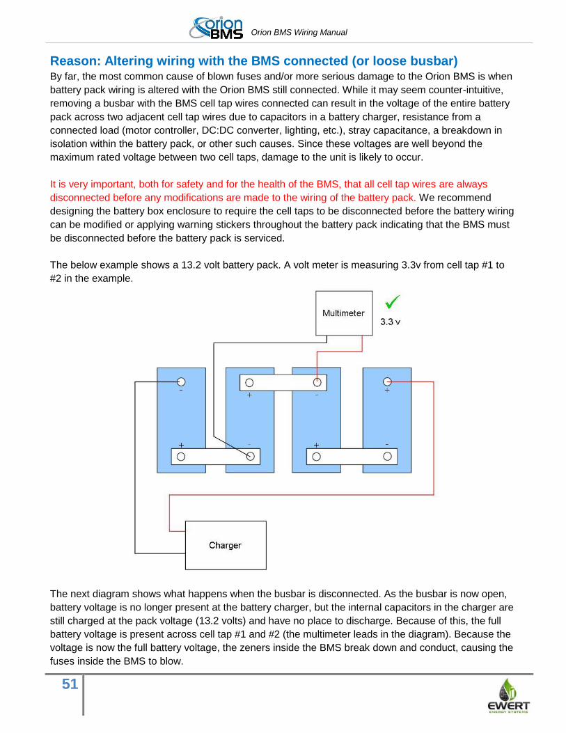
Orion BMS Wiring Manual
51
Reason: Altering wiring with the BMS connected (or loose busbar) By far, the most common cause of blown fuses and/or more serious damage to the Orion BMS is when
battery pack wiring is altered with the Orion BMS still connected. While it may seem counter-intuitive,
removing a busbar with the BMS cell tap wires connected can result in the voltage of the entire battery
pack across two adjacent cell tap wires due to capacitors in a battery charger, resistance from a
connected load (motor controller, DC:DC converter, lighting, etc.), stray capacitance, a breakdown in
isolation within the battery pack, or other such causes. Since these voltages are well beyond the
maximum rated voltage between two cell taps, damage to the unit is likely to occur.
It is very important, both for safety and for the health of the BMS, that all cell tap wires are always
disconnected before any modifications are made to the wiring of the battery pack. We recommend
designing the battery box enclosure to require the cell taps to be disconnected before the battery wiring
can be modified or applying warning stickers throughout the battery pack indicating that the BMS must
be disconnected before the battery pack is serviced.
The below example shows a 13.2 volt battery pack. A volt meter is measuring 3.3v from cell tap #1 to
#2 in the example.
The next diagram shows what happens when the busbar is disconnected. As the busbar is now open,
battery voltage is no longer present at the battery charger, but the internal capacitors in the charger are
still charged at the pack voltage (13.2 volts) and have no place to discharge. Because of this, the full
battery voltage is present across cell tap #1 and #2 (the multimeter leads in the diagram). Because the
voltage is now the full battery voltage, the zeners inside the BMS break down and conduct, causing the
fuses inside the BMS to blow.
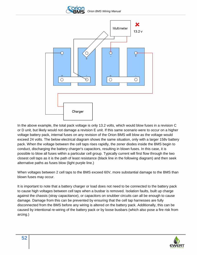
Orion BMS Wiring Manual
52
In the above example, the total pack voltage is only 13.2 volts, which would blow fuses in a revision C
or D unit, but likely would not damage a revision E unit. If this same scenario were to occur on a higher
voltage battery pack, internal fuses on any revision of the Orion BMS will blow as the voltage would
exceed 24 volts. The below electrical diagram shows the same situation, only with a larger 158v battery
pack. When the voltage between the cell taps rises rapidly, the zener diodes inside the BMS begin to
conduct, discharging the battery charger's capacitors, resulting in blown fuses. In this case, it is
possible to blow all fuses within a particular cell group. Typically current will first flow through the two
closest cell taps as it is the path of least resistance (black line in the following diagram) and then seek
alternative paths as fuses blow (light purple line.)
When voltages between 2 cell taps to the BMS exceed 60V, more substantial damage to the BMS than
blown fuses may occur.
It is important to note that a battery charger or load does not need to be connected to the battery pack
to cause high voltages between cell taps when a busbar is removed. Isolation faults, built up charge
against the chassis (stray capacitance), or capacitors on snubber circuits can all be enough to cause
damage. Damage from this can be prevented by ensuring that the cell tap harnesses are fully
disconnected from the BMS before any wiring is altered on the battery pack. Additionally, this can be
caused by intentional re-wiring of the battery pack or by loose busbars (which also pose a fire risk from
arcing.)
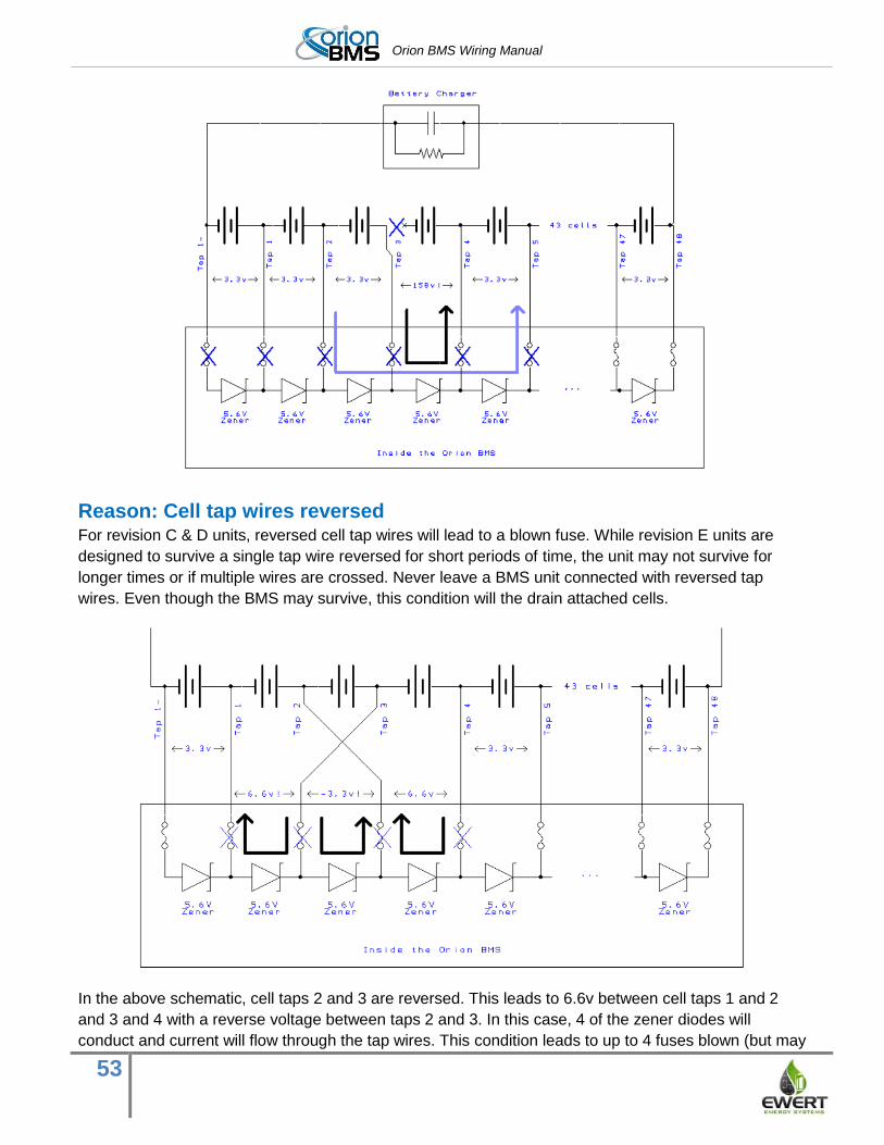
Orion BMS Wiring Manual
53
Reason: Cell tap wires reversed For revision C & D units, reversed cell tap wires will lead to a blown fuse. While revision E units are
designed to survive a single tap wire reversed for short periods of time, the unit may not survive for
longer times or if multiple wires are crossed. Never leave a BMS unit connected with reversed tap
wires. Even though the BMS may survive, this condition will the drain attached cells.
In the above schematic, cell taps 2 and 3 are reversed. This leads to 6.6v between cell taps 1 and 2
and 3 and 4 with a reverse voltage between taps 2 and 3. In this case, 4 of the zener diodes will
conduct and current will flow through the tap wires. This condition leads to up to 4 fuses blown (but may
Orion BMS Wiring Manual
54
be as few as 2 fuses depending on the order that they blow.) For revision E units, fuses will generally
reset to their normal state once the above fault is fixed.
Reason: Accidental contact to cell tap If a cell tap wire accidentally comes into contact with a different voltage cell while the harness is
plugged into the BMS unit, significant voltage may be present. This can also happen if a tap wire is cut
or abrades and shorts to another wire or another terminal. Cell tap wiring must not be altered with the
BMS connected both for safety reasons and to prevent damage to the BMS. Care must also be taken to
route the cabling in such a way that it cannot abrade or be cut by objects.
Reason: Transients (and shorts within the high voltage battery pack) Transients may also cause fuses to blow inside the BMS. Transients are very rapid voltage spikes that
can occur as a result of switching loads, rapid changes in current or other causes. Small transients
occur regularly due to loads switching on and off, and the BMS is designed to withstand these common
transients. Very large transients, typically caused by shorts within a battery pack or by hard switching
very large loads, can be very high voltage and can cause damage, not only to the BMS, but also to
lithium-ion cells.
Reason: Extremely weak cell, internal cell failure (fairly rare) When current is flowing through the battery pack, high resistance connections within the battery pack
can cause “voltage drop” that will cause higher or lower voltages at certain cell taps. This most
commonly occurs with extremely weak cells or faulty cells which have become internally open. This
failure is fairly rare. If cells have become over-discharged or over-charged, the cell impedance will
become very high. The BMS will not allow charge or discharge if it detects a seriously under-charged or
over-charged cell. However, if the user ignores the BMS and continues to charge or discharge, the cell
can cause significant voltage drop (or in some cases reverse voltages) that can cause fuses to blow.
Differences between Revision E and previous revisions Revisions C & D of the Orion BMS contain standard fuses. Once these fuses blow in these units, the
unit must be serviced and the fuses replaced. Fuses in these units will blow if voltages exceed 5.5v or if
there is reverse voltage below 0v.
Revision E of the Orion BMS also contain standard fuses, but these units also contain additional
resettable fuses which protect against certain kinds of temporary lower voltage wiring faults. In most
cases where the over voltage or reverse voltage conditions are less than 24 volts for less than 10
minutes, the resettable fuses will reset to normal after the fault is cleared. In situations where faults
result in higher voltages across two cell taps, the standard fuses are designed to blow. If this occurs,
the BMS must be returned for service.
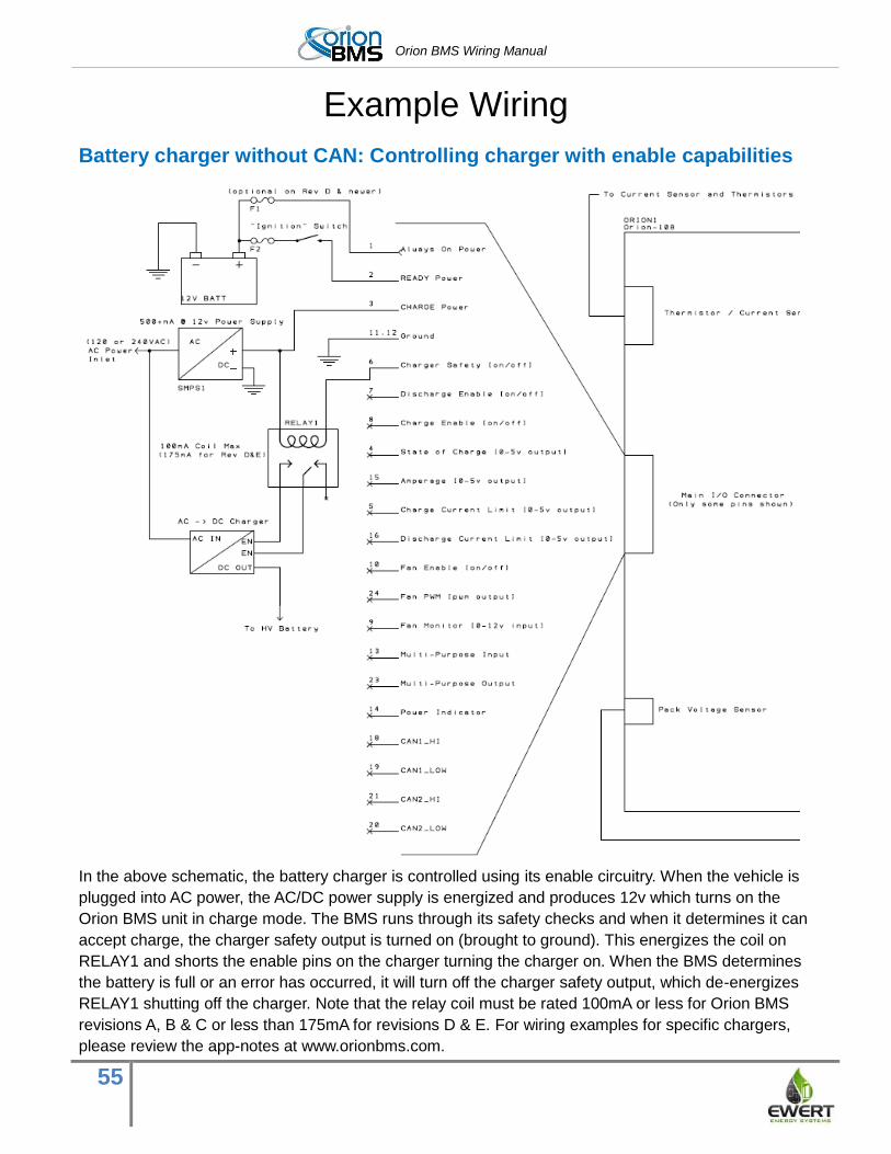
Orion BMS Wiring Manual
55
Example Wiring
Battery charger without CAN: Controlling charger with enable capabilities
In the above schematic, the battery charger is controlled using its enable circuitry. When the vehicle is
plugged into AC power, the AC/DC power supply is energized and produces 12v which turns on the
Orion BMS unit in charge mode. The BMS runs through its safety checks and when it determines it can
accept charge, the charger safety output is turned on (brought to ground). This energizes the coil on
RELAY1 and shorts the enable pins on the charger turning the charger on. When the BMS determines
the battery is full or an error has occurred, it will turn off the charger safety output, which de-energizes
RELAY1 shutting off the charger. Note that the relay coil must be rated 100mA or less for Orion BMS
revisions A, B & C or less than 175mA for revisions D & E. For wiring examples for specific chargers,
please review the app-notes at www.orionbms.com.
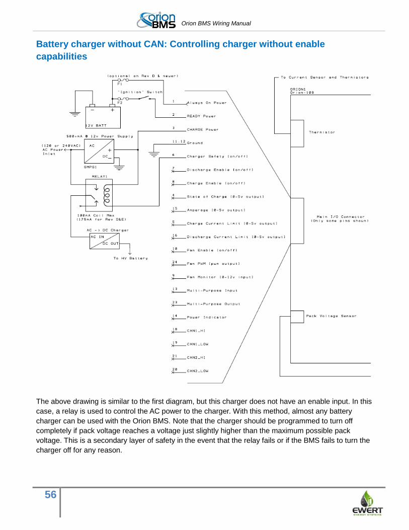
Orion BMS Wiring Manual
56
Battery charger without CAN: Controlling charger without enable
capabilities
The above drawing is similar to the first diagram, but this charger does not have an enable input. In this
case, a relay is used to control the AC power to the charger. With this method, almost any battery
charger can be used with the Orion BMS. Note that the charger should be programmed to turn off
completely if pack voltage reaches a voltage just slightly higher than the maximum possible pack
voltage. This is a secondary layer of safety in the event that the relay fails or if the BMS fails to turn the
charger off for any reason.
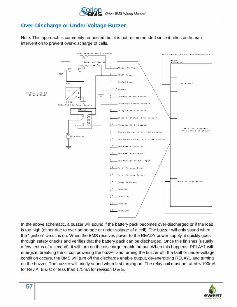
Orion BMS Wiring Manual
57
Over-Discharge or Under-Voltage Buzzer
Note: This approach is commonly requested, but it is not recommended since it relies on human
intervention to prevent over-discharge of cells.
In the above schematic, a buzzer will sound if the battery pack becomes over-discharged or if the load
is too high (either due to over-amperage or under-voltage of a cell). The buzzer will only sound when
the “ignition” circuit is on. When the BMS receives power to the READY power supply, it quickly goes
through safety checks and verifies that the battery pack can be discharged. Once this finishes (usually
a few tenths of a second), it will turn on the discharge enable output. When this happens, RELAY1 will
energize, breaking the circuit powering the buzzer and turning the buzzer off. If a fault or under-voltage
condition occurs, the BMS will turn off the discharge enable output, de-energizing RELAY1 and turning
on the buzzer. The buzzer will briefly sound when first turning on. The relay coil must be rated < 100mA
for Rev A, B & C or less than 175mA for revision D & E.


![Index []...74 WoodStoCk RoAd B3 Classics Centre ioAnnou CentRe foR ClASSiCAl And ByzAntine StudieS, 66 St gileS’ B5 Continuing education eWeRt HouSe, eWeRt PlACe, SuMMeRtoWn (off](https://static.fdocuments.in/doc/165x107/5fe14fa3fb3bfe055065cab4/index-74-woodstock-road-b3-classics-centre-ioannou-centre-for-classical.jpg)