WirelessHART Modeling and Performance Evaluationpcuijper/docs/QEES/MFC/dsn.pdfWirelessHART Modeling...
40
WirelessHART Modeling and Performance Evaluation Anne Remke and Xian Wu October 24, 2013 A. Remke and X. Wu (University of Twente) WirelessHART October 24, 2013 1 / 21
Transcript of WirelessHART Modeling and Performance Evaluationpcuijper/docs/QEES/MFC/dsn.pdfWirelessHART Modeling...

WirelessHART Modeling and Performance Evaluation
Anne Remke and Xian Wu
October 24, 2013
A. Remke and X. Wu (University of Twente) WirelessHART October 24, 2013 1 / 21

WirelessHART [www.hartcomm.org]
A. Remke and X. Wu (University of Twente) WirelessHART October 24, 2013 2 / 21

Introduction
Control applications
I switch from wired communication to Wireless
I reduced installation costs and increased flexibility
I can be adapted during runtime
I involves multiple communication hops
Challenge is the predictability!
Recent work by Alur, Pappas et al. introduces
I formal syntax and semantics for multi-hop WirelessHart
I different kinds of link failure models
I sufficient conditions for stability in control loop if only single link fails
A. Remke and X. Wu (University of Twente) WirelessHART October 24, 2013 3 / 21

This work
Proposes to
I separate failure model from control analysis
I allows to consider the possible failure of all involved links
Computes reachability probabilities
I for certain messages, paths or networks
I evaluates influence of different parameters
I takes into account different failure models
I could be included into control analysis directly
A. Remke and X. Wu (University of Twente) WirelessHART October 24, 2013 4 / 21

WirelessHART protocol
I feedback controlI field devices are source and relay nodesI gateway is routing destination
I pseudo-random frequency channel hopping and channel blacklistingI to avoid channel overlaping and to reduce interference
I network layer determines routingI upstream and downstream graph routing
I data link layer defines strict 10 ms time slots
I Time Division Multiple Access (TDMA)I for collision-free and deterministic communicationsI one transmission per slot
I MAC layer is slotted and synchronizedI series of consecutive slots forms super-frame
A. Remke and X. Wu (University of Twente) WirelessHART October 24, 2013 5 / 21

Radio connectivity graph
s2Plant
Wireless Control Netowork
s1
a1
v1
a2
s3
a3
v2
v3
v4
v5
v6
v7
controller
A. Remke and X. Wu (University of Twente) WirelessHART October 24, 2013 6 / 21

Model information flow
s2Plant
Wireless Control Netowork
s1
a1
v1
a2
s3
a3
v2
v3
v4
v5
v6
v7
controller
Static routing
I v1 → v4 → controller, v2 → v5 → controller, v3 → v6 → v7 → controller
Communication schedule with superframe of size 7
η = (〈v1, v4〉, 〈v2, v5〉, 〈v3, v6〉, 〈v4, c〉, 〈v5, c〉, 〈v6, v7〉, 〈v7, c〉)
.A. Remke and X. Wu (University of Twente) WirelessHART October 24, 2013 7 / 21

WirelessHART parameters
Super-frame
I all field nodes share the same super-frame of size (Fs)
I slots are specifically allocated to field devices to transmit uplink/downlink
Reporting interval
I frequency at which measurements are taken and communicated (Is)
I reduced frequency saves wireless communiciation overhead and extendslife-time of field devices
Message life cycle
I Time-to-Live (TTL) defines message life time
I TTL is decreased with each slot (uplink OR downlink)
A. Remke and X. Wu (University of Twente) WirelessHART October 24, 2013 8 / 21

Hierarchical path model
Information flow
I each flow periodically generates packets at source
I passes it through to its destination
Time-triggered nature of the protocol
I iterate through slots of superframe and
I schedule possible transitionsI idle slot (if communication schedule does not allow a transmission)I successful orI unsuccessful transmission
Compositional model per path
I state reflects age of the message at each hop (age1, age2, . . . , agen)
I unique initial state (1, 0, 0, . . . , 0)
I allows to include failure probabilities
A. Remke and X. Wu (University of Twente) WirelessHART October 24, 2013 9 / 21

Underlying link model for transient failures
UP DOWN
pfl
prc
1-pfl 1-prc
I successful transmission of each bit with probability 1−BERI for WirelessHART message with L bits
I results in failure proability of pfl = 1− (1−BER)LI recovery prc = 0.9 for transient failures
For links in transient state:
[ps(t), pf (t)] = p(t) = p(0)
[1− pfl pflprc 1− prc
]tFor links in steady-state:
[ps, pf ] = [π(up), π(down)] = [prc
prc + pfl,
pflprc + pfl
]
A. Remke and X. Wu (University of Twente) WirelessHART October 24, 2013 10 / 21

Example DTMC for 3-hop path
Reporting interval is Is = 1, uplink frame-size Fup = 7 andcommunication schedule η = (∗, 〈n1, n2〉, ∗, ∗, 〈n2, n3〉, ∗, 〈n3, G〉)
1,-,- 2,-,- 3,-,- 4,-,- 5,-,- 6,-,- 7,-,-
3,3,- 4,4,- 5,5,- 6,6,- 7,7,-
6,6,6 7,7,7
R7
Discard1
ps1
pf1
ps2
pf2
ps3
pf3
1
1 1
1
1
1
1
1
1
A. Remke and X. Wu (University of Twente) WirelessHART October 24, 2013 11 / 21

Predictability measures
Reachability
I probability that message generated at source reaches gateway beforeend of given reporting interval
Delay
I time difference between Tborn and Trec, which equals the age of a message
I delay distribution τ can be derived from transient distribution of the DTMC
Utilization
I indicates fraction of slots that transmitted irrespective of success
I directly relates to network communication overhead and power consumption
A. Remke and X. Wu (University of Twente) WirelessHART October 24, 2013 12 / 21

Typcial WirelessHART network
Real plant settings according to HART Communication Foundation
I 30% of nodes communicate directly with gateway access points
I about 50% are two hops away
I remaining 20% may be 3 or 4 hops away
Link layer availability
I WirelessHART MAC layer payload length is 127 bytes
I for BER = 1 ∗ 10−4 it follows pfl = 0.0966 and π(up) = 0.9031
A. Remke and X. Wu (University of Twente) WirelessHART October 24, 2013 13 / 21

Connectivity graph of a typcial WirelessHART network
A. Remke and X. Wu (University of Twente) WirelessHART October 24, 2013 14 / 21

Connectivity graph of a typcial WirelessHART network
Parameters
I reporting interval is 4
I superframe size for uplink is 20
I ηa = (〈n1, G〉, 〈n2, G〉, 〈n3, G〉,〈n4, n1〉, 〈n1, G〉, 〈n5, n1〉, 〈n1, G〉, 〈n6, n2〉, 〈n2, G〉, 〈n7, n3〉, 〈n3, G〉,〈n8, n3〉, 〈n3, G〉, 〈n9, n6〉, 〈n6, n2〉, 〈n2, G〉, 〈n10, n7〉, 〈n7, n3〉, 〈n3, G〉)
A. Remke and X. Wu (University of Twente) WirelessHART October 24, 2013 14 / 21

Robustness against transient link failures
0 1 2 3 4 5 60
0.1
0.2
0.3
0.4
0.5
0.6
0.7
0.8
0.9
1
Time slot
tra
nsie
nt
UP
pro
ba
bili
ty
steady−state probability when pfl=0.184
transient UP probability when pfl=0.184
steady−state probability when pfl=0.05
transient UP probability when pfl=0.05
A. Remke and X. Wu (University of Twente) WirelessHART October 24, 2013 15 / 21

Reachability
Table: The reachability probabilities with a link failure lasting one cycle
Path number 3 7 8 10
Hop number 1 2 2 3
Reachability (%)
without link failure 99.92 99.64 99.64 99.07
with link failure 99.51 98.30 98.30 96.28
BottleneckThe longest path with the lowest availability forms the bottleneck of the system.
A. Remke and X. Wu (University of Twente) WirelessHART October 24, 2013 16 / 21

Utilization
Table: Influence of π(up) on the utilization rate of the example network
Link availability 0.693 0.774 0.83 0.903 0.948 0.989
Utilization rate 0.313 0.297 0.283 0.263 0.25 0.24
Bad linksnot only degrade the control stability but also introduce more communicationoverhead and power consumption.
A. Remke and X. Wu (University of Twente) WirelessHART October 24, 2013 17 / 21
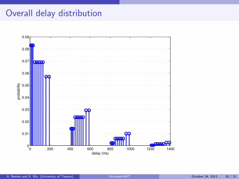
Overall delay distribution
0 200 400 600 800 1000 1200 14000
0.01
0.02
0.03
0.04
0.05
0.06
0.07
0.08
0.09
delay (ms)
prob
abili
ty
A. Remke and X. Wu (University of Twente) WirelessHART October 24, 2013 18 / 21

Expected delays with different schedules
1 2 3 4 5 6 7 8 9 100
100
200
300
400
X= 10Y= 421.409
path
X= 7Y= 317.9528
expe
cted
del
ays
(ms)
Schedule ηa
Schedule ηb
A. Remke and X. Wu (University of Twente) WirelessHART October 24, 2013 19 / 21

Reachability probabilities with Is = 2 and Is = 4
A. Remke and X. Wu (University of Twente) WirelessHART October 24, 2013 20 / 21

Conclusions
WirelessHart
I is able to deliver reliable service under typical industrial environments
I important to choose parameters appropriate to achieve stable control
ContributionI Tool to automatically derive the DTMC
I for a specific network,I communication schedule,I routing graph, andI reporting interval
I and to compute predictability measuresI reachabilityI delay distributionI utilization
A. Remke and X. Wu (University of Twente) WirelessHART October 24, 2013 21 / 21