Wireless Tutorial Part 1 Our G-enealogy – History and Evolution of Mobile Radio
Wireless World ELECTRONICS, RADIO, TELEVISION
Editor:
F. L. DEVEREUX, B.Sc.
Assistant Editor:
H. W. BARNARD
Editorial:
P. R. DARRINGTON D. C. ROLFE D. R. WILLIAMS
Drawing Office.
H. J. COOKE
Production:
D. R. BRAY
Advertisements:
G. BENTON ROWELL (Manager)
J. R. EYTON-JONES
VOLUME 70 No. 5
PRICE: 2s 6d.
FIFTY -FOURTH YEAR OF PUBLICATION
MAY 1964
211 Editorial Comment
212 Television Picture Black -Level
217 Thames Navigational Service
219 "S" Correction
222 H. F. Predictions -May 223 Manufacturers' Products
229 Transistor h Parameters
233 World of Wireless
235 Personalities
237 News from Industry
239 International Audio Festival and Fair
242 Elements of Transistor Pulse Circuits -5 247 Letters to the Editor
252 Recent Technical Developments
253 Transistor Tester
257 A Crossword for Numerates
258 Graphical Aids to Noise Measurement
260 May Meetings
262 " Free Grid "
by P. L. Mothersole
by F. D. Bate
by D. N. Tilsley
by T. D. Towers
by M. F. Sizmur
by A. J. Key
by M. D. Wood
Managing Director : W. E. Miller, M.A., M. I.E. R.E.
Iliffe Electrical Publications, Ltd., Dorset House, Stamford Street, London, S.E.1
Please address to Editor, Advertisement Manager or Publisher as appropriate
C o N T E N T S
© Iliffe Electrical Publications Ltd., 1964. Permission in writing from the Editor must first be
obtained before letterpress or illustrations are reproduced from this journal. Brief abstracts or comments are allowed provided acknowledgement to the journal is given.
PUBLISHED MONTHLY (4th Monday of proceeding month). Telephone: Waterloo 3333 (70 Imes) Telegrams: " Ethaworld London Telex. " Cables: " Ethaworld, London, S. E.1. " Annual Subscriptions: Home £2 Os Od, Overseas £2 5s Od. Canada and U.S.A.
;6.50. Second -class mail privileges authorised at New York, N.Y. BRANCH OFFICES: BIRMINGHAM: King Edward House,
New Street, 2. Telephone: Midland 7191. BRISTOL: 11, Marsh Street, 1. Telephone: Bristol 21491/2. COVENTRY: 8 -10,
Corporation Street. Telephone: Coventry 25210. GLASGOW: 123, Hope Street, C.2. Telephone: Central 1265 -6. MANCHESTER:
260, Deansgate, 3. Telephone: Blackfriars 4412. NEW YORK OFFICE: U.S.A.: 111, Broadway, 6. Telephone: Digby 9 -1197.
www.americanradiohistory.com

72 WIRELESS WORLD MAY, 1964
AA119- SUBMINIATURE DIODE for Radio and Television
ANEW SUBMINIATURE POINT -CONTACT DIODE, the AA119, has recently been introduced by Mullard for use in
detector and discriminator circuits in television and radio receivers. The device is used singly in the sound -detector stage of the latest television and a.m. radio receivers, and in pairs in the ratio- detector stage of f.m. radio sets.
The AA119 is a subminiature ver- sion of the Mullard 0A79 point - contact diode, which has been used successfully for many years in radio and television receivers. The electrical characteristics of the two devices are similar, and the AA119 can be used as a direct replacement for the earlier type. Its maximum reverse peak voltage is 45V and its maximum forward peak current is 100mA. Its reverse current at a reverse voltage of 45V and an ambient temperature of 25 °C is less than 350A. The all -glass envelope of the AA119 measures only 7.6mm in length and 2.7mm in diameter, compared with the 12.7mm and 5mm of the 0A79. This reduction in size enables the AA119 and its associated components to be built into the can of a miniature i.f. transformer.
Magnified 6 times
U.I.F. TUNER VALVES FOR BBC -2
PC86, PC88
Although test transmissions for the second BBC television pro-
gramme have been taking place for several months, BBC -2 starts officially this month. In dual- standard receivers de- signed to accommodate this new programme, the r.f. amplifier of the u.h.f. tuner must provide adequate gain with a good margin on stability and a low noise factor. To achieve these at high fre- quencies, the valve must have a high value of mutual conductance, low values of inter -electrode capac- itance and a low value of grid-
lead inductance. In the Mullard PC88, these are achieved by the use of (i) a frame grid which facilitates the close positioning of the electrodes and gives a high mutual conductance, (ii) an asym- metrical arrangement of the elec- trodes whereby the anode faces only one side of the cathode instead of surrounding it, thus reducing inter- electrode capaci- tances, and (iii) multiple pin con- nections to the grid to minimise lead inductance. The companion u.h.f. valve, type PC86, designed for operation as an oscillator mixer, has a symmetrical electrode structure incorporating a frame grid, and is also provided with multiple connections between the grid and base pins.
8W W -108 FOR FURTHER DETAILS.
EH9O -F.M. Sound
Discriminator Valve
economic circuit for BBC -2
In the f.m. sound -detector stage required in dual- standard receivers for the BBC -2 transmissions, con- siderable economy can be achieved by using a locked- oscillator dis- criminator in place of the more
conventional f.m. ratio detector. The expensive ratio -detector trans- former is replaced by a simple tuned circuit, and switching be- tween the f.m. detector and the detector for the a.m. sound signals of the 405 -line programmes is more readily effected. The Mullard heptode, type EH90, is well suited to this type of detector circuit. The principle of operation of the discriminator is that the magnitude of the mean output current of the valve is a function of the phase relationship between the i.f. signal and local oscillator signal applied respec- tively to the first and third grids of the valve. The circuit demands good electron coupling between these two grids and a good fre- quency-to- amplitude transfer characteristic, and these are pro- vided by the EH90.
MVE 3246
www.americanradiohistory.com

Illegal Broadcasting
WIRELESS WORLD, MAY 1964
Wireless World VOL 70 NO 5 MAY 1964
THE publicity given by the newspapers to the exploits of the vessel "Caro- line " off the Essex coast has redirected attention to the problems of illegal broadcasting.
Article 7, Section 1, § 1, (422) of the Radio Regulations issued by the Inter- national Telecommunication Union (Geneva 1959) states : "The establishment and use of broadcasting stations (sound broadcasting and television broad- casting stations) on board ships, aircraft or any other floating or airborne objects outside national territories is prohibited." Furthermore, the Broad- casting Receiving Licence issued by the Postmaster General in the U.K. is limited to the reception of messages ". . . from authorized Broadcasting Stations . and ... from licensed amateur Stations." So it is clearly as illegal for the man in the street to receive as it is for others to originate such unauthorized transmissions.
Why should such conduct be declared illegal? Because the demands for space in the radio-frequency spectrum are so numerous that chaos will be (some would say has been) the result of failure to agree internationally on its orderly use. But it is one thing to make a law and quite another to enforce it. In theory the P.M.G. can revoke the licence of any listener caught using his set to receive " Radio Caroline " or any other illicit broadcast, and prosecute him if he then uses the set without a licence. He can make representation through the I.T.U. to any of the governments who were signatories to the 1959 Geneva agreement to repudiate the registration and licensing of the ship concerned and so add to the difficulties of keeping the vessel in commission, but he can do little, under present maritime law, to stop the broadcasting unless the ship happens also to be navigated in such a way as to become a danger or hindrance to navigation on the high seas. Then the U.K. might be asked by the Comité Maritime International or by the International Court of Justice to act as the country best situated to deal with the matter. But there is little use in talking of " piracy," which is the stealing of property on the high seas, until maritime law is extended to cover the thieving of ether space. This could be done, for law is a growing thing which has shown itself capable of adaptation to the effects of other modern inventions.
Although " Radio Caroline " has been the pretext for this comment, we have no wish to make her the scapegoat for all the lawlessness at present abroad in the world of radio communications. Hers is merely the latest in a series of cases of off -shore broadcasting including " Atalanta " (off Harwich), " Veronica " (off Holland) and " Courier " the ship station of " Voice of America " which, even if she is in Greek territorial waters off Rhodes, is nevertheless a long way from her national three -mile limit.
Such is the congested state of the ether on medium waves that even anarchists are finding difficulty in effecting an entry, and must constantly shift frequency to avoid heterodynes from this or that station. They sometimes argue that they are doing no one any harm if they can find and use a temporarily unoccu- pied bit of ether space - rather like parking a car on a disused bomb site. But where does this sort of thing end? Soon we may find someone trying to time - multiplex the B.B.C's transmissions by filling in the intervals between the end of a programme and the start of the interval signal. In this context the interval signal might be construed as a form of anticipatory jamming, which reminds us that all forms of retaliatory jamming mean a loss of spectral bandwidth and a squandering of a commodity which is in short supply.
Before we get too self- righteous about " Radio Caroline " let us put our own house in order. More than 50% of long- and medium -wave broadcasting stations in Europe are at present operating on frequencies other than those allo- cated by the 1948 Copenhagen Plan-now long overdue for revision. Let us go no further than to say that in the present " free- for -all " some people have recently drawn attention to themselves by being a little more "free" than most.
211
www.americanradiohistory.com

THE main failing of a mean -level a.g.c. system in a television receiver is the virtual loss in the d.c. component of the video signal. In this
article, which is based on a paper read before the Television Society,' a new technique is described for effectively re- inserting this component by pro- ducing a separate brightness signal from the video output and applying it as a correction signal to the control grid of the picture tube. This technique considerably increases the contrast of low key scenes and simplifies the adjustment of the receiver bright- ness and contrast controls. The problems associated with a.g.c. systems and the d.c. component are briefly discussed as an introduction to this tech- nique.
Mean -level a.g.c. is now used almost exclusively in domestic receivers produced for use in the United Kingdom. This technique effectively suppresses the d.c. component of the video signal. " The result is deleterious to the displayed picture', particularly when the picture information has a low mean value, as for example on low key night scenes. When the d.c. component is suppressed the black -level varies depending on the mean picture content. The effect is illustrated in the title picture j-; the right hand side being correctly displayed, the left hand side has the d.c. component suppressed.
In a receiver the a.g.c. potential should be related to the true signal level for correct gain control action. With positive vision modulation the black -level or back porch following the synchronizing pulse is the only true measure of the received signal amplitude. Some form of gate circuit is therefore required in the a.g.c. system to prevent video information influenc- ing the control potential.
The critical assessment and development of a satisfactory gate circuit has been the subject of previous work'. In a dual -standard 405/625 -line receiver, however, the circuit is further complicated by the change in vision modulation from positive
tThe various processes involved in reproducing an off- the -screen picture- photography, blockmaking and printing -inevitably intro- duce some degradation. -ED.
TELEVISION
CORRECTION AND
STABILIZATION IN
DOMESTIC RECEIVERS
to negative' and the necessity to provide a single contrast control for the user that has substantially the same range of operation on both systems.
In practice, the overall performance of receivers employing mean -level a.g.c. has been found to be satisfactory. A wide range of signal strengths can be accepted by the receiver and variations in the picture due to reflections from aircraft minimized *. The major short -coming of mean -level a.g.c. is the effective suppression of the d.c. component of the video signal. However, even when black -level a.g.c. is employed many receiver designers attenuate the d.c. component to reduce the interaction between the brightness and contrast controls and also to pre- vent excessive beam currents being taken by the picture tube.
The normal technique for stabilizing the black - level of a video signal in transmission equipment is to use a keyed clamp, or sometimes a d.c. restorer circuit when the synchronizing pulses are of a con- stant amplitude. Such circuits can only operate with a very high impedance load, such as the control grid of a valve.
In domestic receivers it is normal practice to d.c. couple the video amplifier valve to the detector circuit and to attenuate the d.c. component of the video signal in the coupling between the anode of the video valve and the cathode of the picture tube. Cathode drive for the picture tube is used since it results in a higher effective tube slope and at the same time separation of the synchronizing pulses is simply achieved from the video output waveform in which they are positive going. It is therefore practi- cable to incorporate a simple clamp or d.c. restorer circuit only at the grid of the video valve.
Three typical video signals are shown in Fig la and the effect of mean -level a.g.c. in Fig lb. It is
* During the time a reflected signal's synchronizing pulse, corre- sponding to zero transmitter output with positive modulation, is coincident with the back porch of the direct signal, a black -level a.g.c. system is completely insensitive to the reflected signal. This situation exists to some extent with all reflections having a delay time of less than about 10 psec and is a serious failing of black -level circuit in conjunction with position modulation.
212 WIRELESS WORLD, MAY 1964
www.americanradiohistory.com

PICTURE BLACK -LEVEL
By P. L. MOTHERSOLE,* M.I.E.R.E., A.M.I.E.E.
apparent that clamping the tips of the synchronizing pulses to a constant potential does not re- insert the d.c. component since the action of mean -level a.g.c. is to vary the amplitude of the video signal to hold the mean -level constant.
A keyed clamp in the grid circuit of the video valve would stabilize the black -level as illustrated in Fig. lc, but the operation of such circuits in a domestic receiver has been found to be unsatisfac- tory. The clamp circuit precedes the video ampli- fier and synchronizing pulse separator. Overshoots, superimposed on the back porch of the video signal by a simple clamp circuit, can give rise to spurious outputs from the separator circuit and also line blanking of the picture tube is essential. Further- more, the d.c. gain of the video stage must be maintained and complications also arise with no signal input to the receiver.
In practice, the displayed picture on a receiver with the black -level of the video signal clamped, together with a mean -level a.g.c. system, was found to be distinctly superior to that of a normal receiver. As illustrated in Fig. lb mean -level a.g.c. causes a variation of both the black -level and peak ampli- tude of the video signal. However, the variation of the black -level on low key scenes was found to be the most serious short -coming of mean-level a.g.c. A technique of stabilizing the black -level suitable for a domestic receiver was therefore devised.
From the waveforms illustrated in Fig. lb and c, it will be apparent that the clamp circuit effectively shifts the d.c. level of the signal. Since conventional clamping cannot be employed in the video amplifier an alternative technique is to generate a correction or bright- ness control signal and apply it to the picture tube grid so that the effective grid -cathode drive waveform is as illustrated in Fig. lc. The correction signal re- quired for application to the control grid is shown in Fig. ld.
This technique appears to be advantageous for a domestic receiver since the operation of such a brightness correction cir- cuit is independent of the other receiver circuits including the
Fig. I. Typical video waveforms show- ing the effect of mean -level a.g.c.
WIRELESS WORLD, MAY 1964
o
ALL BLACK
a.g.c. system and hence of the system switching in a dual -standard receiver.
Generation of the Correction Signal The required correction signal can best be generated from the video output signal. The change in mean - level of the video signal at the control grid of the synchronizing pulse separator is inversely propor- tional to the correction signal required. The actual mean-level change however, is a function of the loop gain of the a.g.c. system and in practice this is high so that the change in mean -level is very small and does in fact vary with signal strength.
In the black -level a.g.c. circuit previously devel- oped' a peak detector was used to produce a d.c. potential directly related to the black -level of the video signal. This circuit used a synchronizing pulse cancelled arrangement but, since a circuit is now re- quired to operate in conjunction with a mean -level a.g.c. system, such techniques are unsatisfactory due to the amplitude variation of the synchronizing pulse with video information (Fig. lb). An alternative black -level detector circuit that is independent of the amplitude of the synchronizing pulse was therefore devised. This circuit, with the additional com- ponents forming the brightness control circuit indi- cated is shown in Fig. 2. The operation of the circuit is as follows :
The video signal is d.c. coupled to the screen grid * Mullard Research Laboratories.
rL =f1
(a.) TRANSMITTED SIGNAL
o-
n
ALL WHITE SAWTOOTH
TL
(b) VIDEO OUTPUT WITH MEAN -LEVEL A.G.C. APPLIED TO C.R.T. CATHODE
O
(C) VIDEO OUTPUT WITH MEAN -LEVEL A.G.C. AND BLACK -LEVEL CLAMPED
o
(d) D.C. CORRECTION SIGNAL REQUIRED BY C.R.T. GRID FOR BLACK -LEVEL STABILIZATION
213
www.americanradiohistory.com
z PFL 200 VIDEO
AMPLIFIER
II I 0.47p. j
47k
47k
+H .T.
I00k
I I 0.05µ
27k
+ H.T.
50k BRIGHTNESS
CONTROL
47k
EFBO BRIGHTNESS
CONTROL VALVE
z PFL 200 SYNCHRONIZING
PULSE SEPARATOR
I00k
IM
MEAN -LEVEL - A.G.C.
CONTRAST CONTROL
+H.T.
IM 2.2M
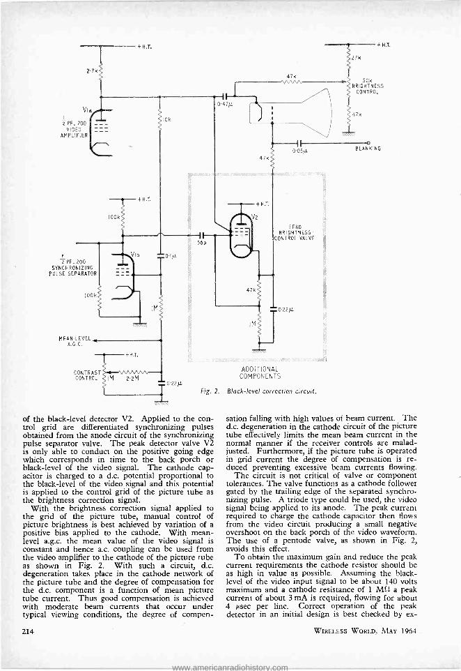
Fig. 2.
of the black -level detector V2. Applied to the con- trol grid are differentiated synchronizing pulses obtained from the anode circuit of the synchronizing pulse separator valve. The peak detector valve V2 is only able to conduct on the positive going edge which corresponds in time to the back porch or black -level of the video signal. The cathode cap- acitor is charged to a d.c. potential proportional to the black -level of the video signal and this potential is applied to the control grid of the picture tube as the brightness correction signal.
With the brightness correction signal applied to the grid of the picture tube, manual control of picture brightness is best achieved by variation of a positive bias applied to the cathode. With mean - level a.g.c. the mean value of the video signal is constant and hence a.c. coupling can be used from the video amplifier to the cathode of the picture tube as shown in Fig. 2. With such a circuit, d.c. degeneration takes place in the cathode network of the picture tube and the degree of compensation for the d.c. component is a function of mean picture tube current. Thus good compensation is achieved with moderate beam currents that occur under typical viewing conditions, the degree of compen-
214
ADDITIONAL COMPONENTS
Black -level correction circuit.
o BLANKING
sation falling with high values of beam current. The d.c. degeneration in the cathode circuit of the picture tube effectively limits the mean beam current in the normal manner if the receiver controls are malad- justed. Furthermore, if the picture tube is operated in grid current the degree of compensation is re- duced preventing excessive beam currents flowing.
The circuit is not critical of valve or component tolerances. The valve functions as a cathode follower gated by the trailing edge of the separated synchro- nizing pulse. A triode type could be used, the video signal being applied to its anode. The peak current required to charge the cathode capacitor then flows from the video circuit producing a small negative overshoot on the back porch of the video waveform. The use of a pentode valve, as shown in Fig. 2, avoids this effect.
To obtain the maximum gain and reduce the peak current requirements the cathode resistor should be as high in value as possible. Assuming the black - level of the video input signal to be about 140 volts maximum and a cathode resistance of 1 Mil a peak current of about 3 mA is required, flowing for about 4 µsec per line. Correct operation of the peak detector in an initial design is best checked by ex-
WIRELESS WORLD, MAY 1964
www.americanradiohistory.com

amination of the valve current monitored across a 1 kSl resistor connected into its anode circuit.
The time constant of the brightness correction circuit is determined by the cathode network in the peak detector circuit and it should be about the same value as that in the picture tube cathode circuit. To minimize the degeneration in the cathode circuit of the picture tube the total resistance should be as low as possible and a value of about 100 kil seems satis- factory with a coupling capacitor of 0.47 µF. Some receiver designers favour a reduction in the video frequency response at about 10 to 20 c /s. This can be readily achieved by suitable choice of these two time constants.
The choice of time constant can also influence the behaviour of the picture tube at switch off. In order to ensure the flow of beam current during the switch -off transient to eliminate the switch -off spot, a longer time constant for the picture tube grid circuit may be desirable. The final choice of capacitor value being influenced by the switch -off characteristic of the particular receiver design.
Practical Results The circuit shown in Fig. 2 has been incorporated in several domestic receivers with surprisingly good results. The d.c. compensation is not quite perfect since the peak detector has a gain of less than unity and the d.c. degeneration in the cathode network of the picture tube reduces its effectiveness at high mean currents. However, under critical viewing conditions of low ambient illumination the error is almost undetectable by critical observers. The sub- jective effect of a combination of mean-level a.g.c. and stabilized black -level is to increase the contrast range of the picture, particularly in low key scenes.
In certain receiver designs complications can arise due to the use of a "high -level " contrast control and the coupling arrangements from the video detector to the video amplifier.
In a television receiver employing mean-level a.g.c., it is possible to use a.c. coupling in the video channel without causing further distortion to the video signal. For example, the video detector can be a.c. coupled to the video amplifier. There are
Fig. 3. An a.c.- coupled black -level correction circuit. When a high -level contrast control is used the 0.47 µF capacitor instead of being connected to the anode goes to the slider.
2.7k
Via
PFL 200 VIDEO
AMPLIFIER
+H.T.
I HIGH -LEVEL CONTRAST CONTROL
z PFL 200
SYNCHRONIZING PULSE SEPARATOR
IOOk
MEAN -LEVEL A.G.C.
IOU k
+H.T.
110k
It O.47ft
¡look
+ H T
27k M/VVA.
47kv
--t----+H.T. fV2
1--
CONTRAST CONTROL
WIRELESS WORLD, MAY 1964
i
ADDITIONAL COMPONENTS
0 05/[
I OO k
EF 80
BRIGHTNESS ^- ,JTROL VALVE
BLANKING
250k BRIGHTNESS
CONTROL
220k
215
www.americanradiohistory.com
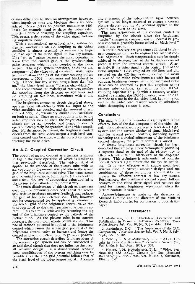
certain difficulties to such an arrangement however, when impulsive noise and blocking effects are con- sidered. Noise peaks on positive modulation (405 lines), for example, tend to drive the video valve into grid current charging the coupling capacitor. This causes a depression of the video signal follow- ing impulsive noise.
With a conventional mean -level a.g.c. system on negative modulation an a.c. coupling to the video amplifier is almost essential to remove the large d.c. "sit up" of the video signal on low key scenes. This " sit up " arises because the a.g.c. potential is taken from the control grid of the synchronizing pulse separator which is a.c. coupled to the video output. The a.g.c. system therefore, holds the a.c. component of the video signal constant. With nega- tive modulation the tips of the synchronizing pulses correspond to 100% modulation and black -level to 77 %. Hence, low key scenes have, a large d.c. " sit up," the black -level going " blacker- than -black."
For these reasons the majority of receivers employ d.c. coupling from the detector on 405 lines and a.c. coupling on 625 lines, sometimes with a d.c. restoration diode.
The brightness correction circuit described above, operates most satisfactorily with the input to the video amplifier a.c. coupled and d.c. restored or a.c. coupled only, i.e., reasonably similar d.c. conditions on both systems. Since an a.c. coupling prior to the video amplifier may be used, the brightness control circuit can be a.c. coupled and hence render its operation completely independent of the video ampli- fier. Furthermore, by driving the brightness control circuit from the same video output a high level con- trast control can be employed, the correction circuit tracking the video drive.
An A.C. Coupled Correction Circuit The circuit of an a.c. coupled arrangement is shown in Fig. 3 the basic operation of which is similar to that previously described. The video signal is applied to the cathode of the picture tube with an a.c. coupling in the normal way and also to the screen grid of the brightness control valve. The mean screen grid potential is varied to form the brightness control, and a fixed d.c. level of appropriate value applied to the picture tube cathode in the normal way.
The main disadvantage of this circuit arrangement over the one previously described is that the screen grid resistor produces negative feedback and reduces the gain of the peak detector V2. This, however, can be compensated for by applying a potential to the screen grid of the brightness control valve that is proportional to the mean picture tube beam cur- rent. This is simply achieved by returning the top end of the brightness control to the cathode of the picture tube. As the picture tube beam current increases, the mean d.c. cathode potential rises. This rise of cathode potential is applied to the brightness control which causes the screen grid potential of the brightness control valve to increase and hence the control grid of the picture tube to go more positive.
The correction circuit described is independent of the receiver a.g.c. system and can be considered as an additional circuit that does not influence the over- all receiver design. In a dual- standard receiver some simplification of the system switching may be possible since the c.r.t. grid potential follows that of the black -level of the video output signal. Accurate
216
d.c. alignment of the video output signal between systems is no longer essential to ensure a correct picture display but the A1 potential applied to the picture tube must be the same.
The user adjustment of the contrast control is simplified by the circuit since the brightness "tracks" changes in contrast, and the normal bright- ness control is probably better called a " black -level " control and pre -set.
In certain receiver designs some additional bright- ness compensation may be required for manual con- trast adjustment. Such compensation may be simply achieved by deriving part of the brightness control potential from the contrast control circuit. Alter- natively, if the video signal at the control grid of the video amplifier is d.c. coupled on 405 lines and d.c. restored on the 625 -line system, so that the mean current of the video valve increases with increased contrast, brightness compensation for increased video drive can be obtained by part d.c. coupling to the picture tube cathode, i.e., shunting the 0.47µF coupling capacitor (Fig. 3) with a resistor, or alter- natively returning the 100kf? resistor, from the c.r.t. cathode to a tap in the d.c. video load, i.e., to the top end of the video load resistor when an additional video decoupling resistor is used.
Conclusions The main failing of a mean -level a.g.c. system is the effective loss of the d.c. component of the video sig- nal. In dual- standard receivers a black -level a.g.c. system and the correct display of signal black -level call for several pre -set controls, involving system switching and a critical adjustment of the brightness control whenever the picture contrast is varied.
A simple brightness correction circuit has been described that employs a new technique of providing a separate signal to the grid of the picture tube to effectively stabilize the black -level of the displayed picture. This technique is independent of both the normal receiver a.g.c. circuit and the system switch- ing. It is very effective with simple mean -level systems used in current receiver designs and the combination of these techniques considerably in- creases the effective contrast of low key scenes. Furthermore, the brightness control signal follows changes in the video drive signal and reduces the need for manual brightness adjustment when the picture contrast is varied.
Acknowledgement is made to the directors of Mullard Limited and the directors of the Mullard Research Laboratories for permission to publish this paper.
REFERENCES
1. Mothersole, P. L. " Black -level Correction and Stabilization in Domestic Television Receivers," Tele- vision Society Jnl., Vol. 10, No. 9, Jan.-Mar., 1964.
2. Birkinshaw, D.C. " The Importance of the D.C. Component," Television Society Ynl., Vol. 7, No. 3, July - Sept., 1953, p. 105.
3. Doherty, S. N. & Mothersole, P. L. " A.G.C. Cir- cuits in Television Receivers," Television Society Vol. 8, No. 9, Jan. -Mar., 1958, p. 350.
4. Haslett, J. H. & Mothersole, P. L. " Video, Syn- chronising and A.G.C. Circuits for Dual Standard Receivers," 7n1. Brit. I.R.E., Vol. 24, No. 5, November, 1962, p. 357.
WIRELESS WORLD, MAY 1964
www.americanradiohistory.com

Recent Extensions of the
THAMES NAVIGATIONAL SERVICE
TELECOMMUNICATIONS, in the widest sense, form the basis of and indeed make possible the present excellent service to mariners entering
the Thames estuary. Masters and pilots of ships carrying v.h.f. telephone equipment can, by calling up either Gravesend Radio or Medway Radio, obtain detailed information of visibility, height of tide, state of traffic and anchorages, etc., upon which to plan their movements on entering congested waters and negotiating the bends of the river.
The experimental service at Gravesend, covering the critical areas R and S in the accompanying chart, has proved so successful that it has now been extended to " see " round Coalhouse and Lower Hope Points and out as far as Southend and the No. 3 Sea Reach Buoy. From there onwards the Thames radar overlaps and is supplemented by the Medway radar at Garrison Point, which will be operational out to the Mid Barrow and Princes Channel. There is direct landline communication between Garrison Point and Gravesend, and also with Thames Haven radar which looks after the local needs of deep- draught tankers.
The important intermediate link between the original Gravesend service and the open estuary depends on a new Decca Type 32 surveillance radar with a 25ft scanner mounted on a 70ft lattice tower at Allen's Hill, Cliffe. Three new display units with off -centring facilities cover areas U, V and W with
an alternative long -range sector (X) which overlaps the Medway No. 3 display area.
The high discrimination of which the Decca 32 is capable has been well preserved in the transmis- sion of the video data from Cliffe to Gravesend by the microwave link, the contract for which was placed with the Telecommunications Division of Elliott Automation Ltd. They were allowed by the Post Office a bandwidth of 30 Mc /s on a carrier in the 7000 -1500 Mc /s band and in this a video signal up to 15 Mc /s is transmitted by single sideband. The accuracy of bearing synchronization called for was beyond the capabilities of analogue methods and a digital system was used in which there are 5000 pulses in 360 °. These pulses are sent on a sub - carrier above the video band, and after reception are compared with similar pulses from the display unit at Gravesend. Phase errors are detected, converted to analogue and used to correct the motor speed of the display scanner.
Remote control and monitoring of the radar trans- mitter /receiver at Cliffe is carried out by u.h.f. (450 Mc /s) link to Gravesend. There are six con- tinuously- operating monitoring signals and twelve other pulse functions, as well as an engineer's speech circuit for use during maintenance.
In the accompanying view of the Gravesend con- trol room (also in our front cover) will be seen two tidal recorders and above them on the back wall a
THAMES HAVEN RADIO CHANNEL 19
LAND LINE TO GRAVESEND
Ycj !---J,UUTHEND-ON -SEA
CANVEY ISLAND
'Chapman IN'7 Sea Reach
TILBURY Lower Hope
Pt.
DISPLAY AREA N93
Tilbury Dock>
CS).
!:oai hou se Pt
DISPLAY AREA NR5 /
MICROWAVE LINK
GRAVESEND
RADIO CHANNELS 16,12,20
SCANNER t o
SCALE OF NAUTICAL MILES
I 2 3 4
DISPLAY AREA
N ?6
07 R,,¢r Med .
Radar coverage of areas U, V, W and X has been provided by a new scanner at Cliffe, below Lower Hope Point.
WIRELESS WORLD, MAY 1964 217
www.americanradiohistory.com

dial which, at the touch of a switch on the control desk, gives the height at any instant at any of the tide recorders at Tilbury, Southend and Shivering Sands Fort. The latter station is about 14 miles to seaward of Southend and is connected to Southend by a u.h.f. data link. The equipment, by Pye Tele- communications Ltd., is battery- operated (duration
Thames Navigation Service operation room. Duty officers in v.h.f. telephone communica- tion with ships have a plot of anchorages before them on the opposite wall and press- button tidal information from the re- corders and dial on the back wall. In thick weather there would be additional observers in the radar display well.
four months) and transistors are used throughout, including the 450 Mc /s transmitter. The telemetry coding system using a 14 -pulse binary chain gives an accuracy of 12 inches in 32ft., and this part of the equipment has been devised by the Gas Accumu- lator Co. (U.K.) Ltd. who have supplied equipment also for the East Coast Flood Warning Organization.
BOOKS RECEIVED
BBC Handbook 1964. As usual this is a veritable mine of information on the technical, administrative and financial organization of the B.B.C. In addition to the 125 -page reference section, there are sections devoted to television, domestic sound broadcasting, the external services and engineering. In an article entitled " Engi- neering of the New Network," F. C. McLean, the director of engineering, says " In view of the large number of transmitters involved, the need to economize in manpower is all the more apparent, and we are planning these u.h.f. [television] stations to operate with the minimum supervision. Automatic devices are being used to the full." Pp. 256. British Broadcasting Corporation, Broadcasting House, London, W.1. Price 6s.
Transistor Electronics in Instrument Technology, edited by N. I. Chistyakov (translated by G. R. Kiss). Papers presented as part of the conference organized in Moscow in 1956 by the Scientific and Technical Society and giving some insight into the development of junc- tion as well as point -contact transistors in Russia at that time. Pp. 378. Pergamon Press Ltd., Headington Hill Hall, Oxford. Price 80s.
ITV 1964. The major part of the 224 pages of this first Independent Television annual is devoted to pro- gramme matters but the book includes some very useful information on the organization of the Independent Television system in the U.K. Two pages are devoted to each of the 22 stations of the Independent Television Authority giving operating characteristics and a coverage map. There is also a small section devoted to technical operations and another on the programme contractors. Independent Television Authority, 70 Brompton Road, London, S.W.3. Price 7s 6d.
Radio Servicing, Theory and Practice by Abraham Marcus. Third edition of a work originally published in America. Pp. 649. George Allen & Unwin, Ltd., 40, Museum Street, London, W.C.1.
218
World Radio TV Handbook. Details of the world's broadcasting organizations, their stations and operating schedules are given as usual in this eighteenth edition. The section devoted to television is growing with each edition and now occupies some 20 pages. Published in English in Denmark by O. Lund Johansen, this 266 - page handbook is available in the U.K. from William Dawson & Sons Ltd., Cannon House, Macklin Street, London, W.C.Z. Price 24s including postage.
Transistor Circuit Manual, by Allan Lytel. Revised (1964) edition of a succinct reference manual of circuit elements and complete circuits covering a wide range of applications in radio, audio, computers, inverters, etc. American device types are cited throughout and the book was originally published in the U.S.A. English edition (pp. 225) with a preface by W. Oliver is pub- lished by W. Foulsham & Co. Ltd., Slough, Bucks, at 35s.
Electromagnetic Theory and Antennas Parts 1 and 2, edited by E. C. Jordan. Papers presented at a sym- posium in Copenhagen, June 1962, sponsored by Com- mission VI of URSI, the Technical University of Denmark, the Danish Academy of Sciences and the Danish National Committee of URSI. Contains 70 full papers and 55 summaries in the following categories: A, Scattering and Diffraction Theory; B, Anisotropic and Stratified Media; C, Random Media and Partial Coherence; D, Surface Waves, Leaky Waves and Mode Propagation; E, Antenna Theory and Radiating Ele- ments; F, Antenna Arrays and Data Processing. Pp. 1,988, Pergamon Press, Ltd., Headington Hill Hall, Oxford. Price £10 10s.
How Television Works, by W. A. Holm. Second edition of an illustrated non -mathematical account of the prin- ciples. Covers a wide field in some detail and should be useful to the apprentice serviceman as well as instructive to the intelligent layman. Pp. 351. Philips Technical Library. Cleaver -Hume Press Ltd., 10 -15 St. Martins Street, London, W.C.2. Price 35s.
WIRELESS WORLD, MAY 1964
www.americanradiohistory.com

"S" CORRECTION By F. D. BATE,* B.Sc. (Hons.)
INVESTIGATION OF THE EFFECT OF THE 'S" CORRECTION
CAPACITOR IN A LINE SCANNING OUTPUT STAGE
IT is well known that in a line scanning output stage for 110° tubes, having a screen with a large radius of curvature, the shape of the yoke
current with respect to time must be "S" shaped in order to obtain a linear scan.
In Fig. 1, a graph is plotted of the yoke current against distance from the centre of the screen for a typical flat -faced 110° tube, a CME 2302. If the spot is to move across the screen linearly with respect to time then clearly the yoke -current- versus -time graph should be identical in shape to Fig. 1.
The first thing to notice about the graph is that reversing the yoke current produces a similar shaped curve in the opposite direction; thus, mathe- matically the simplest curve which may represent the graph is a cubic equation of the type.
t lia L \Ta/ -a \T, (1)
where 2T, is the time of one scan period and 2 I6 the peak to peak yoke current. Equation (1) is valid for -TX. t T.
Empirically, such a curve fits closely on the experi- mental curve when a has a value equal to 0.20; this is shown in Fig. 1. Theoretically, it may be shown
B00
700
600 E
500
W
2 400
O T 300
200
1002
EXPERIMENTAL CURVE - - THEORETICAL CURVE [EQUATION (2) ]
O POINTS GIVEN BY EMPIRICAL CUBIC LAW
EQUATION(1) a= 0.2
3 4 5 6 7 8 9 10 II 12 13 14 15 16 17 18 19
DEFLECTION DISTANCE, X (cm)
that, if we assume a uniform magnetic field in the yoke and if the centre of deflection remains inde- pendent of the deflection angle then the relation between the yoke current and distance measured from the centre of the screen is given by
i = Const. x
ix' ¡ x'
\ -f-IR --\
2p
(See Appendix A.)
WIRELESS WORLD, MAY 1964
(2)
Equation (2) is also plotted in Fig. 1 to show the agreement between experiment and simple theory taking R = 25 cm, p = 71 cm.
Derivation of "S" shaped Current Waveform The usual method of obtaining this shape of current is to place a capacitor in series with the yoke, see Fig. 2.
The following treatment assumes a loss -less circuit, and that the current shape in the yoke is perfectly symmetrical about the zero deflection point. At the instant t = 0 the switch K, is closed, switch K, being open. This is equivalent to applying a step function of voltage to the circuit of Fig. 2. In the usual Laplace notation this then becomes: -
V = i(s) sL + sC SO (3) where V is the initial voltage on the capacitor C when there is no deflection, and hence no current,
*Thorn- A.E.I. Radio Valves and Tubes.
20 21 22 23 24 25 26
Left: -Fig. I. Plot of yoke current against deflection distance from the centre of the tube.
Below: -Fig. 2. Cir- cuit using "S " cor- recting copacitor C.
219
www.americanradiohistory.com

LIST OF SYMBOLS USED a = Numerical value of the cubic term. C = " S " correcting capacitor. i = Instantaneous current in the yoke. i(s) = Laplace transform of i. 2I0 = Peak to peak yoke current with " S "
capacitor, flyback time zero. 2Ii = Peak to peak yoke current with S "
capacitor, and flyback time taken into account. 2T,, the scan time, is the same for Io and II.
k = A constant. L = Inductance of yoke. R = Distance of deflection centre from the
screen. t = Instantaneous time. 2T, = Time of scan. 2T, = Time of flyback. V = H.t. voltage. VL = Voltage across the yoke at any instant
with an " S " capacitor in the circuit. Vo = Voltage across C at the centre of scan. V, = Voltage across capacitor C during the
scan. VF = Voltage across the capacitor C during the
flyback. x = Deflection distance from the centre of the
screen. Radius of curvature of the screen. x2
2 = correction factor for a flat screen.
P
P = ß =
B = Deflection angle.
in the yoke. This is the condition halfway through the scan. From equation (3)
i(s)-V+VO L s2 w;2
1
where 2= 1
LC and using the inverse Laplace notation:
(V -I- Vo) i sin w,t . .
w,L
. (4)
(5)
To find the Initial Voltage Vo
In a line scanning stage without the capacitor C a constant voltage V is across the inductance L during the whole of the scan time and roughly half a sine wave of voltage during the flyback interval. The mean value of the voltage across the inductance over the complete cycle being zero. If, for simplicity, we assume that including the capacitor C does not affect the flyback pulse, (this capacitor is in series with the capacitor determining the flyback time and is normally very much greater than it) and also that the flyback time is zero, then the mean value of the voltage across the inductance during the scan time will not be affected by the presence of the
t vs
EQUAL AREAS
T5 - *i Fig. 3. Voltage across the capacitor C if the flyback time is ignored.
220
t vs
EQUAL AREAS rItRR vvuR5t - INCREASE DURING SCAN
-'v t - Ts Tf
Fig. 4. Voltage across the capacitor taking into account the flyback time.
capacitor C. Thus we can write down that
V T, T VL d
where VL is the voltage across the inductance. Now
since VL = Ldi dt
equation (6) becomes
VT, = JLdt1 dt = LJdi = LIo (7)
o
. (6
where Io is the value of the current when t = T,. Io is also obtained by putting t = T, in equation (5) and combining this with equation (7) gives
(V + Vo) sin w,T, = V w,T .. (8) This gives the initial voltage Vo, hence equation
(5) can be written as VT, Io sin w,t i = sin w,t =
Lsin w,T, sin we're Clearly Io is independent of w,. It will be noticed that, according to the theory given above, introducing an ' S ' correcting capacitor does not change the size of the scan but only the linearity. In practice introducing the capacitor does result in an increase of scan size and the reason for this is the finite time of the flyback. For the moment let us consider equation (7) and expand sin w,t and sin w,T, to the first two terms only. Equation (7) then becomes
(9)
L 1 - Ta2 \11 61BC (T,) 3
j.. (10)
( /
V T,
6LC
the similarity between equation (10) and equation (1) is thus striking and if a = T,2/6LC they are identical.
Thus a linear scan will be produced if: T2
C 6La .. (11)
As a typical example T, = 25µsec (i; scan time) L = 5.2 mH a = 0.2
Thus C = 0.10 µF This compares very favourably with the value of
C found in practice. It does, however, depend upon there being no ripple voltage on the h.t. supply line. A series arrangement of the scanning valve and diode, which gives a boosted h.t. line, usually has a small ripple voltage already deliberately introduced, so that, in this case, the value of C calculated, from equation (il) will be too small, that is, it will produce too much " S " correction.
WIRELESS WORLD, MAY 1964
www.americanradiohistory.com

Fig. 5. Diagram showing the deflection ongle O and deflec- tion distance X.
Effect of the " S " Correction Capacitor Upon Scan Size
As mentioned previously, the introduction of a capacitor C in series with the yoke results in an increase in the scan size, a common explanation of this is that the capacitor cancels out part of the inductance, giving an effective lower inductance and hence a larger current. The treatment so far shows that this is not so; all that the capacitor does is to change the linearity of the scan but not the peak to peak value of the current and hence not the scan size. The explanation of the increase in scan size is given when the effect of the flyback time is taken into consideration.
It will now be shown that the effect of the flyback time is to increase the mean value of the voltage during the scanning time; this, accordingly increases the peak value of the yoke current and hence the scan size. Fig. 3 and Fig. 4 illustrate this more clearly. In Fig. 3 the voltage V, is drawn for the case when the flyback period is ignored, that is Tr = O. The two shaded portions in between 0 & T3 are equal and the mean voltage in this time interval equal to V. In Fig. 4 the finite time of the
C
YOKE
L
H.T.
Fig. 6. Series arrangement of valve and diode showing boost
capacitor C. which produces some "S " correction.
WIRELESS WORLD, MAY 1964
Fig. 7. Parallel arrangement of transistor and diode showing choke L and capacitor C. as used for "S " correction.
flyback is included, and to a first approximation the voltage is assumed to be held constant across the capacitor C during the flyback time. Investigation shows that this simplification is justified since including the more exact waveform which is actually present in this time interval does not significantly affect the result. In Fig. 4 the shaded areas are again equal and it should be clear that the result is to increase the mean value of the voltage during the scan time because the mean value of the voltage during the flyback time is reduced. Investigation shows that to a first approximation the peak scan current is given by
T' T321 IO 1 -F- Ti } Ts 3LC
See Append'x B. s
Also since a = 6LC for optimum linearity,
.. (12)
I, = IO [1 + + TS 2a] .. .. (13)
Assuming that a = 0.2 and TI,f = 0.2. S
I, = 1.07 I,,, that is the peak scan current is increased by about 7 % if a " S " correcting capacitor is used. This is roughly what one obtains in practice with present day flat faced 110° tubes.
The line scan may also be linearized by producing the correct ripple voltage on the h.t. line feeding the yoke, or a combination of this ripple voltage and capacitor in series with the yoke. The latter method is often used in the series arrangement of valve and efficiency diode when the boost capacitor has a small ripple voltage present, see Fig. 6. In the parallel connection of transistor and diode, the h.t. to the line output stage is fed via a choke and capacitor - see Fig. 7 -and all the correction is obtained by choosing the correct value of capacitor, the inductance of the choke having negligible effect, provided it is above a certain minimum value. These methods of linearizing are all essentially the same and a similar analysis holds.
APPENDIX A
In the drawing of Fig. 5, C is the deflection centre which is assumed to remain fixed and to be independent of the scanning angle O (it does actually move slightly towards the tube face as the angle O increases). The radius of curvature of the screen p = SO. The deflection is measured by x, which is drawn perpendicular to CO. Thus we can write down that
x = (R - ß) tan° .. .. .. (14)
221
www.americanradiohistory.com

and from the property of the circle X2 = ß(2p- ß) .. .. .. (15)
or p = P - rp2 - x2 .. .. .. .. (16) within the limits used for ß, p and x we can write approxi- mately
.. (17)
Now, if we assume, for simplicity, that the magnetic field in the yoke producing the scan is a uniform field then it can be shown that the yoke current is simply proportional to the sine of the scanning angle, that is
= kstnO. Using equations (16) and (17) we have that
z i=ksinB=Const. 2
4/X2 R -2 xy
1 (18)
P
This gives too small a value for the current when x becomes large. The reduction of R with increasing x, that is, the movement towards the screen of the deflection centre, will give a value for current larger than equation (18) above. In practice the yoke magnetic field is not uniform, but pincushion, and a more exact treatment would have to include the effect of this.
APPENDIX B
Referring to Fig. 4, we have that the mean value of the voltage across the capacitor C during the scan and flyback time is zero. The value of the voltage during the scan time is given by.
V8 = (V + VD) cos cast -V .. .. (19) and during the flyback time by
VF = (V + V0) cos waTa -V i.e., in this interval the voltage is constant, to a first approximation. Hence
J. T oe(V + Va) cos mat dt + T1 (V + VD) cos waTa
= V(Ta + Ti) . . . . . . .. (20)
H. F. PREDICTIONS - MAY
MOs 40
30
20
15
Io 8
6
5
4
MONTREAL
WITH AURORAL CORRECTION
12 16
G.M.T.
20 0
BUENOS AIRES
IMIEMEM :M::EP:C:
iUIi!IiE' .a.L.c....
This gives
(V + Vo)
or
r sin w,Ts + Tr cos waTa = V (Ta + T1)
wa
11 + Tr) (V + Vo) - waTa Ta (21) sin waTa
11 + ! waTa cot waTa) \\ a
Substituting this value for V + Vo in equation (5) results in the instantaneous yoke current i becoming
VT a
1 +Tr i - " sin wat (22)
L sin waTa 1 + TTs waTa cot w,T,
The peak current It is obtained by putting = T, and is
VT a T, 1+ 1st
Ii = L (23)
1 + T waTa cot waTa Ts
Now if the va ue of It for zero flyback time is II then putting Ti, = 0 'n equation (23) gives
VT e Io
which agrees with equation (7) already obtained. Hence equation (23) becomes
1+ZT-' I=Io "
1 --T,-I; co,T,cot waTi ,
Expanding cot waTa in equation (25) gives
1t^-Io I1 + Ts Ti L Ti T, 3LC
D 4 8 12 16 20 0
G. M.T.
The prediction curves show the median standard MUF, optimum traffic frequency and the lowest usable high frequency (LUF) for reception in this country. Unlike the standard MUF, the LUF is closely dependent upon such factors as transmitter power, aerials, local noise level and the type of modulation: it should gener- ally be regarded with more diffidence than the MUF. The LUF curves shown are those drawn by Cable and Wireless, Ltd., for commercial telegraphy and they serve to give some idea of the period of the day during which communication can be expected.
During the summer months in the minimum of the
222
JOHANNESBURG
(25)
.. (26)
Mc/s 40
30
20
IS
lO
8
6 5
4
0 4 8 12 16 20 0
G. MT.
0 12 16 20 0
G. M.T.
MEDIAN STANDARD MUF
OPTIMUM TRAFFIC FREQUENCY - - -- - - LOWEST USABLE HF
solar cycle past experience has shown that frequencies considerably higher than the predicted standard MUF can at times be received. This effect is mainly confined to daytime on the radio path and has been especially noted on reception in the U.K. from the Far East. The cause is thought to be associated with sporadic -E ionization.
WIRELESS WORLD, MAY 1964
www.americanradiohistory.com

MANUFACTURERS' PRODUCTS
NEW ELECTRONIC EQUIPMENT AND ACCESSORIES
Transistor Oscilloscope TRANSISTORS are used through- out the Type 647 oscilloscope intro- duced recently by Tektronix, Beaver- ton House, Harpenden, Herts. The instrument is designed for operation in extreme environmental condi- tions and the manufacturer specifies the shock, humidity and vibration conditions that the oscilloscope can withstand. The temperature range, over which it can be operated, is -30 °C to + 65 °C and the altitude to which the instrument can be taken and operated is 15,000ft, (non- opera- ting up to 50,000ft). A series of plug -in vertical and horizontal ampli- fiers are available. A 140 msec delay line requires no tuning and permits observation of the leading edge of the waveform that triggers the sweep. The ceramic cathode ray tube has a parallel -ground, glass face- plate, the accelerating potential being 14 kV. A crystal -controlled, 1 kc/s calibrator provides 18 square -wave voltages from 0.2 mV to 100 V in 1 -2 -5 sequence. The frequency is
accurate to within ± 0.1 %. Depending on the plug -in units
used, the bandwidth of the oscillo- scope extends from z.f. to 50 Mc /s. The Type 10A2 dual -trace amplifier permits this bandwidth with a sensi- tivity of 10 mV/ cm to 20 V /cm. The timebase plug -in unit, Type 11B2 employs two separate timebase gen- erators so that calibrated sweep delay is possible. A number of probes are available for use with the instrument. The dimensions are 14Z X 10 x 23in and the weight, with the plug -in units mentioned, is 521b.
8WW 301 for further details
Laboratory Timer A NOTABLE feature of the labora- tory timer Type 3 manufactured by Pioneer Designs, Walton -on- Thames, Surrey, is the pulse- operated trigger circuit with variable sensitivity. A
front -panel control permits the sensi- tivity of the timer to be controlled so that low direct and alternating voltages applied from an external source will start the timed cycle or, alternatively, the sensitivity can be increased to a point where auto- matic cycling takes place. Two time
TIRELESS WORLD, MAY 1964
ranges are incorporated, 0.2 to 1.0 seconds and 1 to 5 seconds. The timed period is infinitely variable between the range limits and is set by a 5in diameter dial. In addition to the triggering facility, the timed cycle may be initiated by a push button on the front panel or by con- necting across two terminals.
A relay provides the output from the unit. Acting as a single -pole, changeover type, the make and break terminals of the relay permit switch- ing of an external circuit, separately fused at 2 A. By rearranging an in- ternal link, the timer can supply 230 V, 50 c /sup to 500 W. The power consumption of the equipment is less than 8 W. 8WW 302 for further details
Multimeter THE Model 101 multimeter manu- factured by Taylor Electrical'Instru- ments, Montrose Avenue, Slough, when used for direct voltage mea- surements has a sensitivity of 100,000 S2 /V. Voltage measurements
(d.c.) can be made over 7 ranges, the lowest being 0.5 V and the highest being 1,000 V. Alternating voltage measurements, at 5,000 t2 /V are made over 5 ranges, the lowest being 10 V and the highest being 1,000 V. Resistance measurements may be made up to 200 W.I. A notable fea- ture is that of a 10µA current mea- suring range. Other ranges extend the measurement of current up to 10 A. A 5 -in scale is provided to- gether with an anti -parallex mirror. The cost of the instrument is ap- proximately £20. 8WW 303 for further details
Aerial Mast OF particular interest to radio amateurs, but with applications in other divisions of the radio industry, a tubular -steel aerial mast is avail- able from John Smith and Co., Rom - ford, Essex. The full height of the equipment is 30ft, the mast being constructed in two sections. The upper tube slides up, or down, be- tween the lower section which con-
Pioneer Designs electronic timer Type 3.
Model 101 multimeter (Taylor Electrical Instruments).
30ft tubular -steel aerial mast available from John Smith & Co
223
www.americanradiohistory.com

sists of two tubular uprights. The movement of the upper section is controlled by a rot -proof rope (" Courlene "). In the extended position, the mast is locked by a re- taining pin and held by 6 adjustable ropes. When the upper section is in its lowered position access is pro- vided to the aerial system by means of tubes welded to the lower sec- tion forming steps. A base plate is supplied with the equipment to- gether with a spindle for a rotating aerial. All " fixed " joints are welded and all the metal parts finished with a silver -grey paint. The complete apparatus costs £25. 8WW 900 for further details
Gaussmeter THE Model 120 gaussmeter, manu- factured by F. W. Bell, Ohio, and available in the U.K. from Living- ston Laboratories, is a direct read- ing instrument for measuring the direction and magnitude of magnetic flux density. The instrument uses an indium arsenide sensing element and direct and alternating fields up to 50 c/s may be measured. Twelve ranges are provided with full-scale readings from 100 milligauss to 30,000 gauss. Fields as low as 10 milligauss can be detected. The accuracy of the gaussmeter is with- in +1% of full scale up to 10,000 gauss. Other features include meter reversing switch, calibration without the need for external standards (ex-
cept for extreme accuracy) and out- puts for recorder and oscilloscope. Accessories include various probes, reference magnets and zero gauss chambers. The instrument costs £230, exclusive of duty. 8WW 305 for further details
Circuit Board RESIN- BONDED boards, 41 X 2fin, perforated by 200 holes spaced every 0.2in, are available from R. and E. Lamb, Queens Road, Leytonstone, London, E.11. Tinned brass eyelets are also available and these can easily be inserted into the boards enabling experimental circuits to be quickly constructed. It is envisaged that the boards will be particularly suited to educational and radio -control applications. Simi- lar size boards, without perforations, are available for insulated backing purposes. Perforated boards cost 2s, plain boards 9d, and packets of 40 eyelets 6d. 8WW 306 for further details
V.H.F. (118 to 136 Mc's) Receiver A TRANSISTOR, v.h.f. receiver in- tended mainly for monitoring aircraft transmissions and for receiving aero- nautical broadcasts is available from Britec, Charing Cross Road, London, W.C.2. Manufactured by Telcom of Switzerland the receiver uses 9 tran- sistors and the sensitivity is 1µV.
Experimental circuit constructed on Lamb "Eyelet Board ".
Model 120 gaussmeter (F. W. Bell).
224
118 to 136 Mc/s re- ceiver manufactured by the Telcom Com- pany of Switzerland. Besides the telescopic aerial, provision is made for connection to aircraft aerials, etc.
Two controls, on /off -volume and tuning, are provided on the front of the equipment together with a large - scale tuning dial calibrated at 'f Mc /s intervals. Audio power output is 1 W The dimensions of the receiver are 8f x 1 6 X nin and the weight, in- cluding battery, is under 21b. The cost of the equipment is £24 13s 6d. 8WW 307 for further details
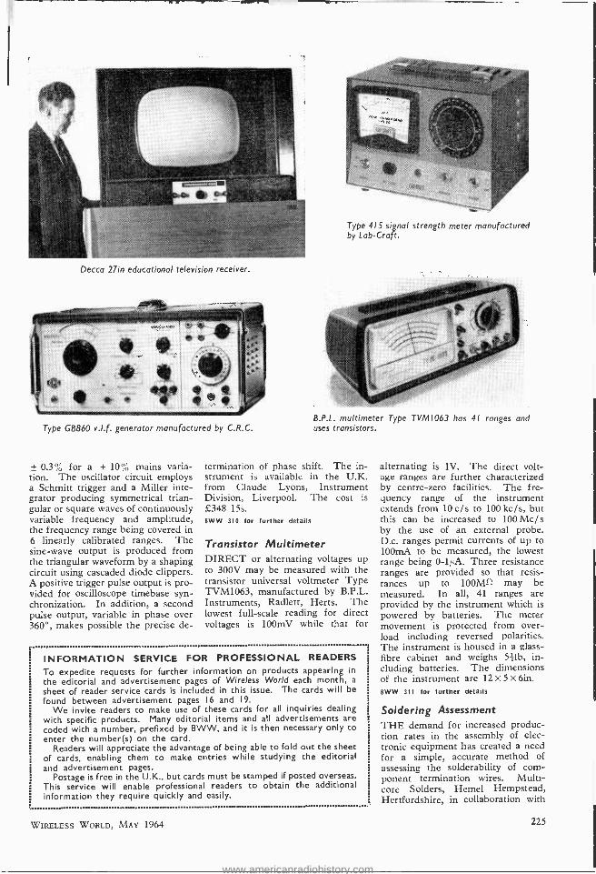
Television Receiver A NUMBER of interesting features are presented by the latest addition to the Decca range of educational equipment. Designed for classroom and school hall use, the Type STV/ 27 television receiver uses a 27in tube and two forward -facing loud- speakers. The housing containing the receiver is about the same size as the average office table. When catches are released, the receiver raises to about 6ft above floor level. The cabinet is finished in a wood - grain Formica. The receiver, which is capable of dual- standard opera- tion, has a 3 W audio output stage. The overall size is 4 X 2.25 X 3.5ft. The 27in receiver can also be obtained for mounting on a tubular trolley. 8WW 308 for further details
U.H.F. Signal Strength A COMPACT signal -strength meter covering Bands IV and V is an- nounced by Lab -Craft, Woodford Bridge, Essex. The Type 415 oper- ates over the frequency range 470 to 860Mc /s and indicates signal strengths from 10 µV to 100 mV in two ranges. The tuning dial is cali- brated both in megacycles and u.h.f. channels. To avoid feeder termina- tion differences between instrument and television receiver, a standard u.h.f. tuner is used in the instrument. A 6:1 reduction drive simplifies tuning and protection is given to overload following an excessive in- put signal. A mains power supply is required. The instrument weighs 9Ib and the dimensions are 7 x 71 X 102in. The cost is £37 10s. 8WW 309 for further details
V.L.F. Generator SINE, square or triangular wave - shapes may be obtained from the Type GB860 very low frequency generator manufactured by C.R.C. (France). The output, approximately f W, is available over a frequency range of 0.001 to 1,000 c /s. Each range is calibrated both in frequency and in period. The accuracy of fre- quency calibration is within ± 2% and the frequency stability is given as
WIRELESS WORLD, MAY 1964
www.americanradiohistory.com
Decca 27ín educational television receiver.
Type GB860 v.l.f. generator manufactured by C.R.C.
± 0.3% for a ± 10% mains varia- tion. The oscillator circuit employs a Schmitt trigger and a Miller inte- grator producing symmetrical trian- gular or square waves of continuously variable frequency and amplitude, the frequency range being covered in 6 linearly calibrated ranges. The sine -wave output is produced from the triangular waveform by a shaping circuit using cascaded diode clippers. A positive trigger pulse output is pro- vided for oscilloscope timebase syn- chronization. In addition, a second pulse output, variable in phase over 360 °, makes possible the precise de-
Type 415 signal strength meter manufactured by Lab - Craft.
B.P.L. multimeter Type TVM1063 has 41 ranges and uses transistors.
termination of phase shift. The in- strument is available in the U.K. from Claude Lyons, Instrument Division, Liverpool. The cost is £348 15s. 8WW 310 for further details
Transistor Multimeter DIRECT or alternating voltages up to 300V may be measured with the transistor universal voltmeter Type TVM1063, manufactured by B.P.L. Instruments, Radlett, Herts. The lowest full -scale reading for direct voltages is 100mV while that for
INFORMATION SERVICE FOR PROFESSIONAL READERS
To expedite requests for further information on products appearing in
the editorial and advertisement pages of Wireless World each month, a
sheet of reader service cards is included in this issue. The cards will be
found between advertisement pages 16 and 19.
We invite readers to make use of these cards for all inquiries dealing with specific products. Many editorial items and all advertisements are coded with a number, prefixed by 8WW, and it is then necessary only to enter the number(s) on the card.
Readers will appreciate the advantage of being able to fold out the sheet of cards, enabling them to make entries while studying the editorial and advertisement pages.
Postage is free in the U.K., but cards must be stamped if posted overseas. This service will enable professional readers to obtain the additional information they require quickly and easily.
alternating is 1V. The direct volt- age ranges are further characterized by centre -zero facilities. The fre- quency range of the instrument extends from 10 c/s to 100 kc /s, but this can be increased to 100 Mc /s by the use of an external probe. D.c. ranges permit currents of up to 100mA to be measured, the lowest range being 0 -1í4A. Three resistance ranges are provided so that resis- tances up to 100MS1 may be measured. In all, 41 ranges are provided by the instrument which is powered by batteries. The meter movement is protected from over- load including reversed polarities. The instrument is housed in a glass - fibre cabinet and weighs 52íb, in- cluding batteries. The dimensions of the instrument are 12 X 5 X 6in. 8WW 311 for further details
Soldering Assessment THE demand for increased produc- tion rates in the assembly of elec- tronic equipment has created a need for a simple, accurate method of assessing the solderability of com- ponent termination wires. Multi- core Solders, Hemel Hempstead, Hertfordshire, in collaboration with
WIRELESS WORLD, MAY 1964 225
www.americanradiohistory.com
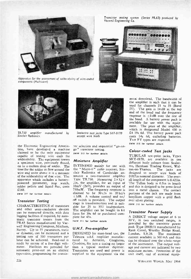
Transistor testing system (Series PR.63) produced by Vacweil Engineering Co.
_.ì
Apparatus for the assessment of solderability of wire -ended components (Multicore)
TR.750 amplifier manufactured by Sinclair Radionics.
the Electronic Engineering Associa- tion, have developed a machine claimed to be the only equipment capable of testing wire ends for solderability. The equipment lowers a specimen wire, previously fluxed, on to a molten drop of solder. The time for the solder to flow around the wire and unite above it is a measure of the solderability of that wire. The apparatus which includes a battery- powered pyrometer, stop watch, solder pellets and liquid flux, costs £168. 8WW 312 for further details
Transistor Testing CHARACTERISTICS of transistors and other semi- conductor devices can be measured directly, with data logging facilities if required, by auto- matic transistor testers from the PR.63 Series manufactured by Vac - well Engineering Company, Mitcham, Surrey. Up to 15 parameters, static or dynamic, can be measured and a testing rate of 500 transistors per hour can be achieved. Read -out is made by means of a five -digit volt- meter. Facilities are provided for automatic print -out on an electric typewriter, programming for transis-
226
Sealectro test jacks Type 5KE -0170 accept wire leads
tor selection and sequential "go -no- go " transistor testing. 8WW 313 for further details
Miniature Amplifier INTENDED mainly for use with the " Micro -6 " radio receiver, Sin- clair Radionics of Cambridge an- nounce a two -transistor amplifier Type TR.750. Measuring 2 x 11 x *in, the amplifier, for an input of 10mV (2kí1), provides an output of 750mW. The frequency response is claimed to be 30 c/s to 20 kc /s ±1dB. A volume control and on/ off switch is provided. The output stage is transformerless and is suit- able for 25 to 3512 loudspeakers. The amplifier can be bought in kit form for 39s 6d or purchased com- plete for 45s. 8WW 314 for further details
U.H.F. Pre-amplifier DESIGNED for mast -head use, the Telextra u.h.f. amplifier manufac- tured by Aerialite, Congleton, Cheshire, fits into a casing no larger than a typical outdoor diplexer. Transistors are used and power is supplied to the equipment via the
aerial downlead. The bandwidth of the amplifier is such that it can be used for channels 21 to 33 (Band IV). The gain is 14 dB at the top end of the band and the frequency response is ±3 dB over the rest of the band. A battery power pack is available for use with the equip- ment. The price of the amplifier, which is designated Model 430 is £4 19s 6d. The battery power pack costs 14s 6d, excluding batteries. Two 9 V types are required. 8WW 315 for further details
Colour -coded Test Jacks TUBULAR test -point jacks, Types SKT -0170, are available in ten different body colours from Sealec- tro, Hersham Trading Estate, Wal- ton-on- Thames. The jacks are designed to accept wire leads of 0.017in nominal diameter. The over- all length of the component is 0.422in. The Teflon body is 0.3in in length and this is designed to be press fitted into a metal chassis. The contact portions of the jack are made from beryllium copper with a gold flash over silver plating. 8WW 318 for further details
Transistor Power Supply A DIRECT voltage output of 6 to 30 V, in two switched ranges, is provided by the transistor power pack Type 18920/1 manufactured by Rank Cintel, Worsley Bridge Road, London, S.E.26. The maximum current available is 500 mA and this can be obtained over the whole range of the instrument. The output volt- age and current are indicated by two miniature meters. Protection of the unit itself, and of external equip-
WIRELESS WORLD, MAY 1964
www.americanradiohistory.com
ment, is given by an electronic over- load protection circuit which includes facilities for automatic and manual reset. Either of the two output terminals can be earthed by means of a short link to the earth terminal. The output impedance is 0.0412 and a change from " no- load " to " full - load " produces a change in the out- put voltage of less than 0.1%. The stabilization is such that a +7'.', mains input voltage variation pro- duces less than 0.1 % change in out- put. Ripple and noise is less than 1 mV peak -to -peak. The accuracies of the meters are within 2.5% and the instrument can be operated up to 35 °C. The dimensions are 5+ X 4 x 72in, the weight 41b 13oz and the cost is £28 15s. 8WW 317 for further details
Dry -reed Relay THE main feature of a new relay (dry reed type) introduced recently by ERG Industrial Corporation, Luton Road Works, Dunstable, is that switching times of 1 msec can be attained; a working life of millions of operations is also claimed.
The gold -plated contacts of the relay are hermetically sealed in an inert atmosphere and are available either as a single changeover (s.p.d.t.) or one normally open contact (s.p.s.t.) The relay is magnetically screened to minimize the effects of external magnetic fields. 8WW 318 for further details
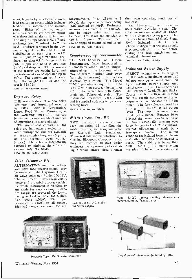
Valve Voltmeter Kit ALTERNATING and direct voltage and resistance measurements may be made with the Daystrom Heath - kit valve voltmeter Model IM -13U. The instrument utilizes a 6 -in 200,ß'A meter and a gimbal bracket enables the whole instrument to be tilted to any angle for easy viewing. Seven d.v. ranges are provided, the lowest having an f.s.d. of 1.5V, the highest f.s.d. being 1,500V. The input resistance is 11M1 on all ranges. Identical ranges are used for a.v.
measurements, ( ±d 5 25 c/s to 1
Mc /s), the input impedance being 1M12 shunted by 40pF. Resistance measurements from 0.1 to 1,000MS2 can be made using an internal battery. Test leads are included in the kit of parts. The instrument can be supplied assembled and tested. 8WW 319 for further details
Remote -reading Thermometer TELEMECHANICS of Totton, Southampton, have introduced a
thermometer which enables temper- atures of up to five locations (which may be several hundred yards away from the instrument) to be read on selection by a switch. The Model T.1050 provides a range of -10 to +50 °C with an accuracy better than 2'C. The meter has both Centi- grade and Fahrenheit scales. The instrument measures 7 X 3+ X 24in and is supplied with one temperature sensing head. 8WW 320 for further details
Micro -circuit Test Kit TWO evaluation micro circuits, each containing 12 thin -film, tin - oxide resistors, are being marketed by Electrosil Ltd., Sunderland. These test kits are manufactured by Corning Electronic Components and they are intended to give design engineers the opportunity of evaluat- ing Corning micro circuits under
Lan -Elec Type L.P.40I stabil- ized power supply.
Heathkit Type IM -I3U valve voltmeter.
WIRELESS WORLD, MAY 1964
their own operating conditions at low cost.
Each 12- resistor micro circuit is on a wafer -176 X;áin in size. The substrate material is alumina, glazed with an alumino- silicate glass. The resistors have values of 5000, 5 and 50k12. Included in the kit is a schematic diagram of the test circuit, a photograph of the circuit before coating and lead attachment and technical information. 8WW 321 for further details
Stabilized Power Supply DIRECT voltages over the range 0
to 30 V with a maximum current of 500 mA may be obtained from the Type L.P.401 power supply unit manufactured by Lan -Electronics Ltd., Farnham Road, Slough, Bucks. Course and fine voltage adjustment controls permit accurate setting of output which is indicated on a 3 .4in
meter. The fine voltage control has a range of ±0.75 V at all output levels. The output current is moni- tored by the meter. Between 50 to 500 mA the current can be set so as to remain essentially constant over large changes in load. The constant - current adjustment is made by a
front -panel control. The output channels are isolated from the chassis and either one may be connected to earth. The stability is better than 5,000:1 for a ±10% mains voltage variation. The output resistance is
Model T.1050 remote - reading thermometer manufactured by Telemechanics.
Two dry -reed relays manufactured by ERG.
227
www.americanradiohistory.com

less than 10 ma Ripple is quoted as being typically less than 500µV peak -to -peak. Prolonged short cir- cuit of the output terminals does not cause any damage to the supply. The unit will operate continuously at full load in ambient temperatures up to +45°C. Mains supplies of 200 to 250 V, 40 to 60 c/s are re- quired but the equipment can be supplied for 110 V alternating power supplies. The instrument measures 6J x 81 x Thin and weighs 9116. The cost is £37 10s. Other versions are available including one rated at 1 A. 8WW 322 for further details
Heavy -duty Audio Tape AMPEX have introduced a new series of colour- coded, audio record- ing tape designed for heavy -duty use. The tape is based on a du Pont Mylar base and a new oxide formu- lation is claimed to prevent the oxide from flaking or rubbing off. The tape is available on red, green, blue, orange, violet and yellow reels. The box binder (in which the tape is packed), reel, trailer and leader are all the same colour. A 5 -in reel contains 600ft of tape and the 7 -in reel 1,200ft. 8WW 323 for further details
Soldering Aid A SOLDER dispenser, that can be attached to many types of soldering irons, is available from Alpha Metals, New Bond Street, London, W.1. The device is clamped on to the handle of the soldering iron and extension tubes can be added or removed to match the dispenser to soldering iron length. The solder is fed through the tube to the tip of the iron, a drive
wheel being employed which enables the operator to move the solder for- wards or backwards. A guide spring is fitted at the rear end of the attach- ment. Advantages claimed for the " Third Hand " solder dispenser in- clude uniform amounts of solder per joint, increased operating speeds, longer tip life (because the solder is placed on the joint and not on the tip) and that one hand is free to hold the component or wire being sol- dered. The device costs £3 8s. 8WW 324 for further details
Oscillogram Projection A NEW oscilloscope accessory, manufactured by Philips and intro- duced recently to the U.K. by Research and Control (now M.E.L. Equipment Co., Ltd.), King's Cross Road, London, W.C.1, is intended mainly for use in lecture rooms. Designated Type PM9301, the accessory consists of an f 2.8 lens with a focal length of 150mm and with it oscillograms may be pro- jected up to 6ft from oscilloscope to screen. Flanges are available for fitting the lens to many types of oscilloscope. 8WW 325 for further details
Silvered Mica Capacitors FIVE new types of capacitors have been added to the Johnson Matthey and Co. range of Silver Star, high - stability, silvered, mica capacitors. Four of the new types, designated Types Al2E, C12E, A22E and A33E, are encapsulated in synthetic resin and capacitors from each type are available in working voltages of 200 and 350 V. Capacitances of up to 47,000 pF can be obtained. The remaining type, the C12S, is syn-
WS switch kit available from Lorlin Electronic Co.
"Third Hand" soldering dispenser manufactured by Invention, Develop- ment and Engineering Associates.
228
thetic resin dipped and is the small- est capacitor in the Silver Star range. Measuring 0.5 x 0.275 X 0.165in, components of this type can be obtained with working voltages of 200, 350 and 50 V. The maximum capacitance available in the 50 V version is 5,000 pF. 8WW 326 for further details
Radio Multiplex Terminal Equipment A NEW 13- channel version of the established Automatic Telephone and Electric Co. Type 900 radio multi- plex terminal equipment is available for use in radio -telephone networks. The equipment is designed to handle a complete group of 12 channels plus an engineer's order -wire circuit. Claimed to be compact and easily in- stalled, the system can provide all the normal dialling, supervisory and metering facilities used in manual or automatic telephone circuits. The bandwidths of the system is 60 kc /s and the design provides for un- attended operation. The multiplex equipment (to C.C.I.T.T. standards) uses transistors throughout. The radio equipment and multiplex equip- ment are mounted in separate racks and the only connections involved are to the mains supply (110 to 250 V, 50 to 60 c /s), aerial feeder and telephone circuit tails. The manu- facturer's address is Arundel Street, London, W.C.2. 8WW 327 for further details
Switch Kit OVER 30 wafer switches of various contact arrangements may be assembled from the Type WS switch kit available from Lorlin Electronic Company, Billingshurst, Sussex. The WS switch design is based on double- sided, spring- contact clips mounted radially at 30° intervals on an insulated stator. The contact blades, mounted on a rotor rotate through the contact clips. The number of circuits controlled on one wafer can, where circumstances per- mit, be doubled by the use of clips mounted on both sides of the wafer, using a special insulator. The maxi- mum switch combinations per one- sided wafer are: 1 -pole, 11 -way; 2- pole, 5 -way; 3 -pole, 3 -way; and O- pole, 2 -way. The contact resistance of the switches is less than 5 mt2, and the insulation resistance is greater than 1,000 Mil. The corn - plete kit is available for £15 and re- placement parts can be easily ob- tained. 8WW 328 for further details
WIRELESS Wotun, MAY 1964
www.americanradiohistory.com

Transistor h Parameters By D. N. TILSLEY, B.sc., Grad.Inst.P., A.M,I.E.R.E
I T is becoming very difficult to avoid the h para- meters, for they are now widely used by manufac- turers of transistors and by writers of text -books.
There they are usually introduced in terms of four terminal network analysis " and " matrix algebra," but they may be approached from a more practical standpoint.
There are four of them, and all are necessary to specify how a transistor will behave, but with a valve only two quantities the g,,, and the ra are needed. Let us first consider why we need the the extra two.
In the case of the valve one does not need to know the input resistance, for unless the grid goes
9
Fig. 1. Valve equivalent Fig. 2. Corresponding transis- circuit. tor equivalent input circuit.
positive, this resistance is many megohms. For this reason the grid g in the equivalent circuit repres- entation of the valve m Fig. 1 does not appear to be connected to anything: the path between the grid g and the cathode k is for practical purposes an open circuit. But the input resistance of a transistor is low, and so its value must be stated; this is hinvui or hi. (Later in this article a more rigorous treatment will show hi to be the input impedance when the output is short circuited).
It is fair to assume that valves do not work back- wards. Applying a potential difference of 1 volt between the anode and cathode will not cause an appreciable voltage to be fed back to the grid. With transistors such feedback does take place, and here an alternating potential of 1 volt applied at the output might cause an alternating voltage of 0.5mV to appear at the input. Here the reverse voltage feedback ratio is 0.5 x 10 -3 or 5 x 10⁻⁴ and the symbol for this is hreverse or h,.
So h r _ Voltage at input Voltage at output
Now this might look like the reciprocal of the voltage gain, but to measure the voltage gain a signal would be applied to the input and the output voltage measured. For hr, of course, we are being uncon- ventional and applying the signal to the output and measuring how much of it appears across the input.
With a voltage of v2 at the output, the voltage appearing at the input will be hrv2, and the input
WIRELESS WORLD, MAY 1964
side of the equivalent circuit for a transistor i represented by Fig. 2.
At high frequencies the input impedance of valve may not, in fact, be infinite, and also there maye bl feedback via the anode -grid capacitance. Whilt to a first approximation both these effects may be neglected in valves, they are far from negligible in transistors and account for hi and h,. respectively.
Of course it is essential to know in which configura- tion the transistor is being used, and this is denoted by a second subscript, b for common base, e for common emitter, and c for common collector. So for example hie is the input resistance of a common emitter connected transistor, and typically it might be about 2k O. If the input voltage were increased by 10mV, then this implies that the input current
would increase by 12kS
- 5µA. Had the tran-
sistor been used in the common base connection a very different value would have been obtained: hi b is typically a few tens of ohms.
The other two h parameters are very roughly equivalent to their valve counterparts, and the complete circuit diagram is shown in Fig. 3. Here hforward or hf corresponds to g,. But there is one very important difference between them. In a valve the output current is proportional to the input voltage. With all three configurations of transistors, the output current is proportional to the input current, but the relation between the output current and the input voltage is a much more complicated one. So our current generator will be supposed to give a current proportional to the input current il, and the constant of proportionality is h,.
This is therefore the current gain, and hfb is the current gain for the transistor in the common base configuration, otherwise (loosely) known as a.
Similarly hfe is the common emitter current gain ß or a'. Manufacturers now usually give this most important quantity its correct title of hie, and the other alternative symbols are gradually being dropped. Perhaps one reason why hfe is preferable to ß is that the sign of ß is regarded as positive by some and as negative by others, depending on the directions in which they regard the input and output currents as flowing. The directions of the currents shown in Fig. 3 are universally accepted, and with this convention hp, is negative, typically -0.95 to
il
¡vis ADMITTANCE
Iva =hD
hr
Fig. 3. Complete transistor equivalent circuit.
229
www.americanradiohistory.com

(z) ( -) Fig. 4. Illustrating the conventions for current direction.
- 0.995, while hf, is positive and usually between 20 and 200.
The reasons for these polarities are illustrated in Fig. 4. Fig. 4(a) shows the common base tran- sistor and here il = IE, but i, = -Ia
i, -aIE So /If b
IE = -a.
In Fig. 4(b) it = -IB = - (IB -Ic) _ -(IE- aIE) = - IE(1 -a)
and i, = -Ic = i, -aIE
So hf, = it = - IE(1 -a) -(1 -a) 1 -a -hf b
i+hfb ß, the common emitter current gain is the collector
current divided by the base current. But does this mean the current flowing into the base? If so, since the direction of current flow is from the base (for a p-n -p transistor) then this base current may
be regarded as negative. So ß could be either 1a a
or
- i -a, depending on the directions in which we
decide to measure the currents. There is no ambiguity with h parameters -the currents are measured inwards, and there is no argument. If you want to measure the currents as flowing out- wards, or one in and one out, you may do so but then you will have your own system, and you must not call your numbers h parameters.
In the equivalent circuit for both valves and transistors the output resistance is connected across the current generator, but here again there is a diff- erence. Fig. 1 shows this resistance as the ra of the valve, but in the transistor circuit of Fig. 3 houcvus or h, is the reciprocal of this resistance, that is, a conductance.
A reasonable value for this output resistance in a common emitter connected transistor might
be 20kí), therefore ho ,,= 1 , - 50 x 10.8 20x103 or 50µmho.
These h parameters are usually for " small signal " operation, that is, we are assuming the transistor to be suitably biased to give the specified d.c. con- ditions, and we are superimposing a signal much smaller than this fired bias. This, of course, is also true for valves. A g,,, of 5mA/V does not mean that a potential difference of 1 volt applied between grid and cathode causes an anode current of 5mA. But it does mean that an alternating potential of
230
10.1 volts superimposed on a suitable bias voltage produces an alternating current of 0.5mA super- imposed on the steady anode current. If the actual d.c. values are intended then the convention is that the subscripts are written in capital letters. For example, the input characteristic of a transistor. in the common base configuration is shown in Fig. 5. htß is the d.c. input resistance and here at VEB = 0.4V, an input current of about 4mA flows and so
here it is 0.4 - 100n. 4x10'3
The small signal input resistance, hi b, at this point is given by the slope of the tangent, and here kb is of the order of 10 sl or 200, since a change of input voltage of 0.1V causes a change in input current of a few milliamps.
Similarly hFE represents the d.c. common emitter current gain, which is the actual value of the collector current divided by the base current flowing. More generally, however, it is the small signal parameters which are used.
In Fig. 3 it will be seen that the input voltage is the sum of the drop across hi plus hrv which is the voltage fed back from the output to the input
v, = hii, + hr)2 . . . . .. (1) Considering the output side, one might expect
i2 to flow in the opposite direction, but the conven- tion is that both i, and i, shall be measured as flowing into the device.
So i, is the sum of the current through the current generator and that flowing through the resistor,
which is v,-- h
or v,ho. This is the reason for
ho being taken as the conductance. Had ho been chosen as the resistance, then this last term would
have been ', which would not look so neat in the
next equation. i, = hfi1 -F hov, .. .. (2)
Some writers use h11, h12, h and h,,. These are identical with our hi, h hi, and ho respectively, and the two equations might have been written.
vt = h,14 -I- h12v, .. .. .. (1) is = h2ä1 -i- hrtvs
The convention here is that a dash denotes the common emitter connection. For example h'71 (read as " h- dash -two -one "), is the same as hf, and is also known as ß or a'.
Equations (1) and (2) may be used to define the h parameters in a more rigorous fashion. Thus to find h, from equation (1), put v, = 0 then v1 =hii1 or hi =11 when v, =0. Now v, =0
1
would be physically realized by placing a large capacitance across the output, forming a short
4
3
Z
o 0'1 01 03 Ee (VOLTS)
Fig. S. Transistor input character- istic.
04
WIRELESS WORLD, MAY 1964
www.americanradiohistory.com

Fig. 6. Bias supply arrangement.
circuit to the " small signal " alternating current, so hi (or h11) might be expressed as
= vi vi
= 0 vi h, or output short circuited il tr
(vi) Similarly h=h12=
v2)i1 =Q 0r input open circuited
(1) 2 t2 and hi. = h21 = or (outvut short circuited
I2
) il tz
ho = h22 = v2 0 Or
(v2) input open circuited
Now hi or h11 is a resistance hr or h12 is a voltage ratio ht or h21 is a current ratio h or h22 is a conductance.
What sort of things are they then? They are certainly parameters, because any number specifying anything at all is called a parameter, but they are a very mixed bag -they are hybrid parameters, and this is their correct name.
The reason for this curious choice is that they can all be measured easily. For example, it would have been possible to use the " Thévenin " form for the output, of a constant voltage generator in series with the output resistance. But the output voltage of this generator has to be found on open circuit, and since the transistor has to be supplied with its d.c. biasing current, there will be a current path through the power supply or battery. Since this path should have a resistance very much greater than that of the output resistance of the transistor, it would have to be of many megohms. Although it is possible to do this (either by chokes of high impedance to a.c. but of low d.c. resistance, or by a series pentode) this difficulty is avoided if the constant current, or " Norton " form is adopted for the generator. Here the short -circuit current must be found, and a load of a few hundred ohms may be regarded as a short circuit compared with the output resistance of the transistor. The " output current with the output short -circuited " is in fact usually found by measuring the p.d. across such a resistor.
Measuring h Parameters A 19th century physicist used to say that he
had difficulty in understanding anything until he had measured it. Certainly one of the best methods of getting the feel of these h parameters is to measure them, so we will now consider how this may be done.
The transistor has only three connecting wires, and so one of these must be common to both the input and the output. We will consider mainly the common emitter configuration since it is the commonest and most useful. But until the transistor has been given its d.c. supplies, it will not work at
WIRELESS WORLD, MAY 1964
all, and a suitable arrangement for obtaining the bias is shown in Fig. 6.
The variable resistor or the voltage of the bast biasing battery should be adjusted to give the required collector current, typically 1mA. Small alternating voltages will now be applied to various parts of the circuit, and the consequent alternating voltages and currents measured at other parts. These will be small fluctuations above and below the direct bias values, and so these alternating currents must be much less than the direct currents, which will be the order of a milliampere. A.c. microammeters do not exist, but a.c. millivoltmeters are in common use, so these small alternating currents are measured by noting the alternating potentials which they develop across a known resistance. In the following measurements, one terminal is always common to both the oscillator and the millivoltmeter, and it is important to ensure that this common terminal is the earthy one in both instruments. If the connec- tions to one instrument were reversed, then either the output of the oscillator may be short -circuited, or excessive mains hum may be picked up by the millivoltmeter. The complete circuit diagram for a unit for the measurement of the h parameters of a transistor- in the common -emitter configuration is shown in Fig. 7(a), and the diagram of a similar unit for the common -base connection is given in Fig. 7(b). Although the procedure is identical for the common base unit, in the following example the common emitter one is taken.
After the correct bias conditions have been ob- tained all d.c. milliammeters and voltmeters should be removed from the circuit, since their inclusion can introduce errors.
An oscillator is connected between A and C, and its output adjusted to be 0.5V. Although not critical, a frequency of about lkc /s is often chosen, since at this low frequency any errors due to the phase shift caused by the transistor should be negligible. The p.d. between B and C should now be measured, and we will assume that it is 7.3mV or 0.0073V. This is very small compared with the input voltage, so the current through the
0.5V 100k fl resistor may be taken as
-100kÛ = 511A,
180 k
100k I ABOUT ±5%
20V
T+
A. oB
IOk
C
(a)
-1 50µo ABOUT I
9V 100 100
±5% ts%
D E
Fig. 7. Circuits for measuring h parameters (a) in the common - emitter and (b) the common -base configuration.
231
www.americanradiohistory.com
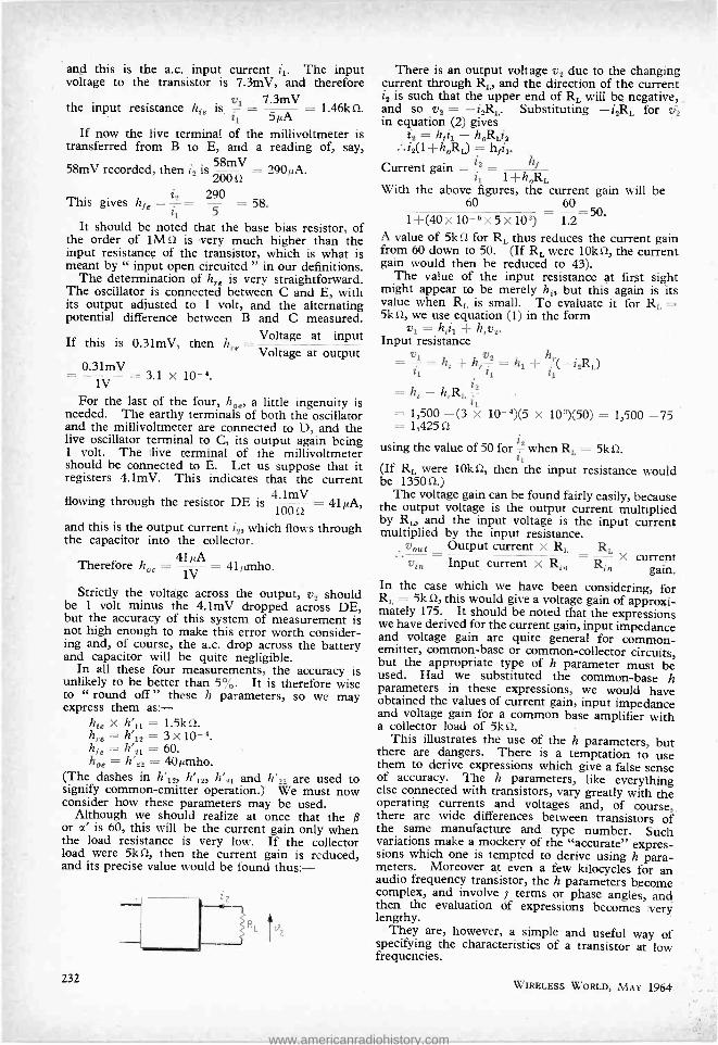
and this is the a.c. input current i1. The input voltage to the transistor is 7.3mV, and therefore
the input resistance h!8 is 1 = S Á = 1.46kí2. 1
If now the live terminal of the millivoltmeter is transferred from B to E, and a reading of, say,
58mV recorded, then i2 is 200 = 290í1A.
This gives h,8 = i=
= 290 = 58.
It should be noted that the base bias resistor, of the order of 1M S2 is very much higher than the input resistance of the transistor, which is what is meant by " input open circuited " in our definitions.
The determination of h,.e is very straightforward. The oscillator is connected between C and E, with its output adjusted to 1 volt, and the alternating potential difference between B and C measured.
Voltage at input If this is 0.31mV then h. ' 1e Voltage at output
_0.31mV 1V = 3.1 x 10 -4.
For the last of the four, hO8, a little ingenuity is needed. The earthy terminals of both the oscillator and the millivoltmeter are connected to D, and the live oscillator terminal to C, its output again being 1 volt. The live terminal of the millivoltmeter should be connected to É. Let us suppose that it registers 4.1mV. This indicates that the current
4.1mV flowing through the resistor DE is 1(1 = 41µA,
and this is the output current i,, which flows through the capacitor into the collector.
Therefore h08 = 4íV = 4lµmho.
Strictly the voltage across the output, v2 should be 1 volt minus the 4.1mV dropped across DE, but the accuracy of this system of measurement is not high enough to make this error worth consider- ing and, of course, the a.c. drop across the battery and capacitor will be quite negligible.
In all these four measurements, the accuracy is unlikely to be better than 5 %. It is therefore wise to " round off " these h parameters, so we may express them as:-
ht x h'11 = 1.5kû. h,8 = h'12 = 3 x 10 -4. hse= ;en =60. hoe = h'22 = 40µmho.
(The dashes in h'12, h'12, h'21 and h'22 are used to signify common- emitter operation.)" We must now consider how these parameters may be used.
Although we should realize at once that the ß or á is 60, this will be the current gain only when the load resistance is very low. If the collector load were 5kû, then the current gain is reduced, and its precise value would be found thus:
232
There is an output voltage v4 due to the changing current through RL, and the direction of the current i2 is such that the upper end of RL will be negative, and so v2 = -i2RL. Substituting -4RL for y2 in equation (2) gives
i2 - hLis i2(1 h0RL) = hfi1.
Current gain = 2 1 } h R
With the above figures, the current gain will be 60 60
=50. 1+(40x10-6x5x10') 1.2 A value of 5k S2 for RL thus reduces the current gain from 60 down to 50. (If RL were 101W, the current gain would then be reduced to 43).
The value of the input resistance at first sight might appear to be merely ht, but this again is its value when RL is small. To evaluate it for RL 5kí2, we use equation (1) in the form
v1 = hti1 + h,.v2. Input resistance
= v1= ht +h,.v2= h1 +hr(- i2R1,)
it tl ii
= ht -h,RL? = 1,500 -(3 lx 10-4)(5 x 10')(50) = 1,500 -75 = 1,425 S2
using the value of 50 for z
when RL = 5k O.
(If RL were 10k02, then the input resistance would be 1350 û.)
The voltage gain can be found fairly easily, because the output voltage is the output current multiplied by RL, and the input voltage is the input current multiplied by the input resistance.
voua Output current x RL =
RL x current
vin Input current x Rt,, R. gain. In the case which we have been considering, for RL = 5k S2, this would give a voltage gain of approxi- mately 175. It should be noted that the expressions we have derived for the current gain, input impedance and voltage gain are quite general for common - emitter, common -base or common -collector circuits, but the appropriate type of h parameter must be used. Had we substituted the common -base h parameters in these expressions, we would have obtained the values of current gain, input impedance and voltage gain for a common base amplifier with a collector load of 5k O.
This illustrates the use of the h parameters, but there are dangers. There is a temptation to use them to derive expressions which give a false sense of accuracy. The h parameters, like everything else connected with transistors, vary greatly with the operating currents and voltages and, of course, there are wide differences between transistors of the same manufacture and type number. Such variations make a mockery of the "accurate" expres- sions which one is tempted to derive using h para- meters. Moreover at even a few kilocycles for an audio frequency transistor, the h parameters become complex, and involve j terms or phase angles, and then the evaluation Of expressions becomes very lengthy.
They are, however, a simple and useful way of specifying the characteristics of a transistor at low frequencies.
WIRELESS WORLD, MAY 1964
www.americanradiohistory.com
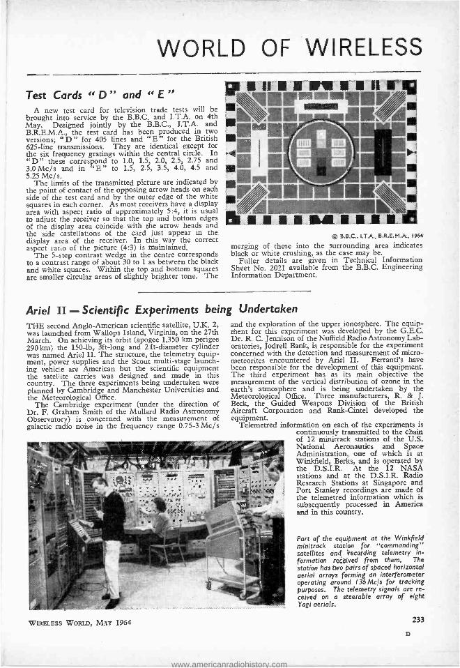
WORLD OF WIRELESS
Test Cards " D" and " E " A new test card for television trade tests will be
brought into service by the B.B.C. and I.T.A. on 4th May. Designed jointly by the B.B.C., I.T.A. and B.R.E.M.A., the test card has been produced in two versions; "D " for 405 lines and "E' for the British 625 -line transmissions. They are identical except for the six frequency gratings within the central circle. In "D" the correspond to 1.0, 1.5, 2.0, 2.5, 2.75 and 3.OMc /s and in `E" to 1.5, 2.5, 3.5, 4.0, 4.5 and 5.25 Mc /s.
The limits of the transmitted picture are indicated by the point of contact of the opposing arrow heads on each side of the test card and by the outer edge of the white squares in each corner. As most receivers have a display area with aspect ratio of approximately 5:4, it is usual to adjust the receiver so that the top and bottom edges of the display area coincide with the arrow heads and the side castellations of the card just appear in the display area of the receiver. In this way the correct aspect ratio of the picture (4:3) is maintained.
The 5 -step contrast wedge in the centre corresponds to a contrast range of about 30 to 1 as between the black and white squares. Within the top and bottom squares are smaller circular areas of slightly brighter tone. The
!r VI r/,
© B.B.C., I.T.A., B.R.E.M.A., 1964
merging of these into the surrounding area indicates black or white crushing, as the case may be.
Fuller details are given in Technical Information Sheet No. 2021 available from the B.B.C. Engineering Information Department,
Ariel II - Scientific Experiments being Undertaken THE second Anglo- American scientific satellite, U.K. 2, was launched from Wallops Island, Virginia, on the 27th March. On achieving its orbit (apogee 1,350 km perigee 290 km) the 150 -1b, 3f t-long and 2 ft- diameter cylinder was named Ariel II. The structure, the telemetry equip- ment, power supplies and the Scout multi -stage launch- ing vehicle are American but the scientific equipment the satellite carries was designed and made in this country. The three experiments being undertaken were planned by Cambridge and Manchester Universities and the Meteorological Office.
The Cambridge experiment (under the direction of Dr. F. Graham Smith of the Mullard Radio Astronomy Observatory) is concerned with the measurement of galactic radio noise in the frequency range 0.75 -3 Mc /s
and the exploration of the upper ionosphere. The equip- ment for this experiment was developed by the G.E.C. Dr. R. C. Jennison of the Nuffield Radio Astronomy Lab- oratories, Jodrell Bank, is responsible for the experiment concerned with the detection and measurement of micro - meteorites encountered by Ariel II. Ferranti's have been responsible for the development of this equipment. The third experiment has as its main objective the measurement of the vertical distribution of ozone in the earth's atmosphere and is being undertaken by the Meteorological Office. Three manufacturers, R. & J. Beck, the Guided Weapons Division of the British Aircraft Corporation and Rank -Cintel developed the equipment.
Telemetred information on each of the experiments is continuously transmitted to the chain of 12 minitrack stations of the U.S. National Aeronautics and Space Administration, one of which is at Winkfield, Berks, and is operated by the D.S.I.R. At the 12 NASA stations and at the D.S.I.R. Radio Research Stations at Singapore and Port Stanley recordings are made of the telemetred information which is subsequently processed in America and in this country.
Part of the equipment at the Winkfield minitrack station for "commanding" satellites and 'recording telemetry in- formation received from them. The station has two pairs of spaced horizontal aerial arrays forming an interferometer operating around 136 Me/s for tracking purposes. The telemetry signals are re- ceived on a steerable array of eight Yogi aerials.
WIRELESS WORLD, MAY 1964 233
D
www.americanradiohistory.com

Baird Television Awards .
MRS. BAIRD, widow of the television pioneer, presented thirty silver medallions at the Baird Television Festival, Royal Albert Hall, on the 16th April to those who have made " a special contribution to television." Most of the medals were awarded to artists, scriptwriters, pro- ducers, etc., but one was given to Thornton H. Bridge- water who worked for four years with John Logie Baird before joining the B.B.C. in 1932 and was associated with the B.B.C.'s transmissions of the Baird 30 -line tests. He was appointed B.B.C. chief engineer (tele- vision) two years ago. Another recipient was Benjamin Clapp who joined Baird in 1926 and was at the receiving end in New York for Baird's transatlantic television tests in February 1928. Mr. Clapp continued with the Baird organization, of which he was chief development engineer, when it became Cinema Television and later Rank Cintel from which he retired last year.
Colour Television. -Mr. Bevins, the Postmaster - General, has accepted the Television Advisory Commit- tee's advice to delay the colour decision until after the meeting of the C.C.I.R. Colour Television Study Group, which is to be held next April. The P.M.G. has also stated that if a decision cannot be reached at this meeting as to which system should be adopted for Europe, Britain will then adopt the system of its choice.
Colour TV Patent Extended. -The High Court has granted E.M.I. a 72 -year extension of a U.K. colour television receiver patent (No. 524443) of Georges Valensi, of Geneva, of which E.M.I. have the sub- licen- sing rights. The extension was granted on the grounds of inadequate remuneration owing to the slow develop- ment of colour television.
BBC -2 Trade Test Transmissions. -With the start of BBC -2 on 20th April, changes have been made to the times of the trade test transmissions. Subject to any day -to -day alterations, which may be necessary because of programme commitments, the new times are as fol- lows on Mondays to Saturdays: 10 a.m. to noon and 2 p.m. to 4 p.m.
Japanese -manufactured domestic radio and electrical appliances are being shown in an exhibition at the Japan Trade Centre, 535, Oxford Street, London, W.I. The exhibition is now open and will remain so until 6th May. A small portable transistor television set is featured and other exhibits include a selection of radiograms, record - players and tape recorders.
Local Sound Broadcasting ? -Answering a question in the Commons recently, Mr. Bevins, the Postmaster - General, said that he is studying with the Minister of Education "the special question of the possible use of local sound broadcasting for educational purposes." In answer to a direct question asking if he would allow the B.B.C. to operate a local station in the city of Leeds, he replied " No. For the present, the Government's policy with regard to local sound broadcasting in general remains as stated in the two White Papers on the Report of the Committee on Broadcasting."
"The sun and the ionosphere" is to be the title of J. A. Ratcliffe's address as president of the Mathe- matics and Physics Section at the annual meeting of the British Association for the Advancement of Science in Southampton (26th August -2nd September). During the annual meeting Prof. W. J. G. Beynon is giving an evening lecture on the International Years of the Quiet Sun.
234
Another First:- End-of-tube picture, taken in London by John Cura, showing the Japanese Prime Minister during the live television transmission from Japan via Telstar 11 relayed by the B.B.C. and I.T.A. on 16th April.
Stereo Broadcasting. -As there is unlikely to be a decision on a European standard for stereophonic broadcasting before the next Plenary Assembly of the C.C.I.R. in 1966, the B.B.C. plans to continue its present series of test transmissions in order to study still further the technical problems involved in introducing a service. It will continue to radiate both its compatible pilot - tone transmissions from Wrotham (91.3 Mc /s) and its dual -transmitter tests. Experimental stereo transmis- sions using the pilot -tone system are also being broad- cast for an hour each week -day from four v.h.f. stations of the Westdeutscher Rundfunk (Langenberg 99.2 Münster 89.7, Nordhalle 98.1 and Teutoberger Wald 97 Mc /s). The Hamburg transmitter of the Nord - deutscher Rundfunk (87.6 Mc /s) is also now regularly radiating stereo programmes each week day.
Gentle Persuasion ? -As a result of enquiries arising from comparisons of licence records and lists of resi- dents, the Post Office authorities persuaded 283,015 householders to buy television and sound radio licences in 1963. Where persuasion failed, the Post Office took legal action and last year 20,699 people were success- fully prosecuted.
A joint U.K. -Netherlands -Scandinavian conference on " Planning and design for protection from noise " is being sponsored by the Society of Acoustic Technology, and will be held in Coventry from 15th -18th June. Details are available from Dr. P. Lord, Department of Pure and Applied Physics, The Royal College of Advanced Technology, Salford, 5.
A new correspondence course on electronics funda- mentals is being offered by the International Cor- respondence Schools. The course (PL 100) comprises 20 lessons each of which includes 300 -500 self -instruction sheets.
A second solid -state physics conference is being planned by the Institute of Physics & Physical Society for next year. It will be held in the University of Bristol from 5th -8th January. Particulars are obtain- able from the Institute, 47 Belgrave Square, London, S.W.1.
One better ? -" Aerials for 626 supplied and fitted ... " states an advertisement in the Farnham Herald.
WIRELESS WORLD, MAY 1964
www.americanradiohistory.com

PERSONALITIES
Sir Ronald German, C.M.G., dir- ector general of the Post Office since 1960, is the president elect of the Electrical Research Association for 1964 -65. Sir Ronald entered the Post Office in 1925 as assistant traffic superintendent and at the outbreak of war became assistant private secretary to the Postmaster- General.
Nathan Hughes, B.Sc., A.M.I.E.E., A.M.I.E.R.E., has been appointed sales manager at Geneva of the In- ternational Division of the Radio Corporation of America. He will be responsible for marketing the company's broadcasting and com- munication products in Europe, the Middle East and Africa. Mr. Hughes, who is 39, has worked in Independent television since 1955, initially as senior engineer with Associated Rediffusion at Wembley, then chief engineer of T.W.W. Cardiff, and since 1961 as general manager of Wales (West & North) Television.
R. J. A. Paul, the deputy head of the department of electrical and con- trol engineering at the College of Aeronautics, Cranfield, has just been appointed to the newly created Chair of Control Engineering in the School of Engineering Science at the Uni- versity College of North Wales, Ban- gor. His appointment fills the third chair in the School of Engineering Science, the others being electronic engineering and materials technology.
J. Kenneth Brown, B.Sc., chief engineer of A.B. Metal Products I td . has beer. appointed to he board of directors, as technical director, a newly created position. Mr. Brown has been with the company for ten years and has spent the last six as chief engineer.
J. Kenneth Brown
WIRELESS WORLD, MAY 1964
A. R. Boothroyd, B.Sc. (Eng.), Ph.D., reader in electronics at the Imperial College of Science and Technology, London, has been appointed to the new chair of elec- tronics at Queen's University, Bel- fast. Dr. Boothroyd, who is 38 and a graduate of Imperial College, re- ceived his Ph.D. for research in the field of network synthesis.
John P. Jeffcock, O.B.E., A.C.G.I., M.I.E.E., F.R.Ae.S., and Stanley S. A. Watkins, A.C.G.I., B.Sc.(Eng.), M.I.E.E., have received fellowships of the City and Guilds of London Institute. Mr. Jeffcock, who is the chairman of the equipment executive board of the Philips organization in the United Kingdom, received his fellowship "for an outstanding con- tribution to the practice of telecom- munications and aeronautics ". Mr. Watkins received his for " contribu- tions to science and technology in the study of sound, both its analysis and its synthesis in relation to speech and in the recording of sound and its synchronization with motion pic- tures ". After studying at the City and Guilds of London Institute, Mr. Watkins spent many of his working years in the United States. Mr. Watkins is nearly 80 and retired some years ago to London.
Leslie B. Copestick, who resigned his managing directorship of Solar - tron Research and Development Ltd. last year, has been appointed chair- man of Fenlow Electronics Ltd. Mr. Copestick was co- founder, in 1948, of Solution and spent most of his 15 years supervising the group's research and development.
J. H. Cosens has retired from the position of editorial director of our publishing company Iliffe Electrical Publications Ltd. Mr. Cosens joined the editorial staff of our sister journal Electrical Review in 1919 from W. T. Henley's Telegraph Works Co. He was appointed industrial editor in 1938 and in 1953 became general editor. Five years ago he was elec- ted to the Board of the company.
M. Wakefield Heffernan has been appointed by Thomson Television (International) Ltd., chief engineer of Gibraltar Television Ltd. Mr. Heffernan, who is 42, was at one time chief television engineer in Cyprus and more recently chief en- gineer of the Western Nigerian Radiovision Service.
Elizabeth Laverick, B.Sc., Ph.D., head of the Radar and Communica- tions Research Laboratory of Elliott Bros. since 1959, is the fifth woman to achieve full membership of the I.E.E.; there are also 33 women asso- ciate members and 62 graduates and students. Dr. Laverick worked for a year at the D.S.I.R. Radio Re- search Station, Slough, before going, in 1943, to Durham University where she studied physics and radio. She obtained her doctorate in 1950 and has been with Elliott's since 1953.
Dr. Elizabeth Laverick
W. H. Thorneycroft, B.Sc., A.M.I.E.E., has been appointed engineer -in- charge of the B.B.C.'s Daventry transmitting station, in suc- cession to H. A. Masters, M.B.E., Assoc.I.E.E., who has recently re- tired after 34 years' service. Mr. Masters joined the B.B.C. in 1930 after service with the Marconi Com- pany and the G.P.O. He went to Daventry in 1933, soon after the inauguration of the B.B.C.'s Empire Service and was appointed assistant e. -in -c. in 1949, and e. -in -c. in 1956. Mr. Thorneycroft joined the B.B.C. in 1936 at the Droitwich transmit- ting station and became a senior maintenance engineer there in 1941. Five years later, he transferred to the short -wave transmitting station at Skelton and in 1952 was ap- pointed assistant e.-in-c. at Washford. In 1958 he was appointed e. -in-c. at Moorside Edge and for the past year has been e. -in-c. at the short -wave station at Rampisham.
The.Medal of Honor of the Insti- tute of Electrical and Electronics En- gineers has been awarded to Harold A. Wheeler " for his analyses of the fundamental limitations on the reso- lution in television systems and on wideband amplifiers, and for his basic contributions to the theory and
235
www.americanradiohistory.com
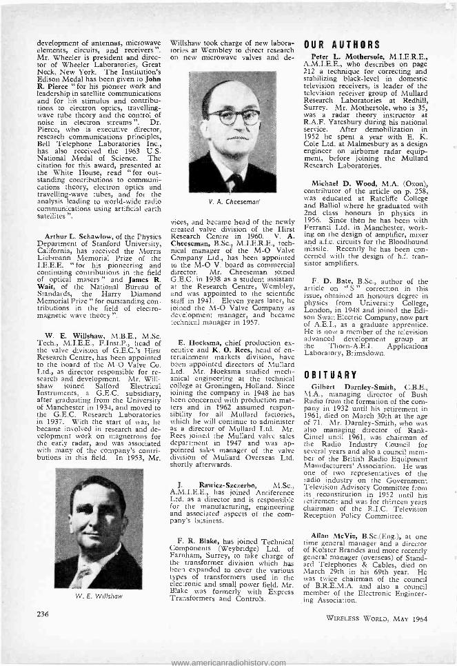
development of antennas, microwave elements, circuits, and receivers ". Mr. Wheeler is president and direc- tor of Wheeler Laboratories, Great Neck, New York. The Institution's Edison Medal has been given to John R. Pierce " for his pioneer work and leadership in satellite communications and for his stimulus and contribu- tions to electron optics, travelling - wave tube theory and the control of noise in electron streams ". Dr. Pierce, who is executive director, research communications principles, Bell Telephone Laboratories Inc., has also received the 1963 U.S. National Medal of Science. The citation for this award, presented at the White House, read " for out- standing contributions to communi- cations theory, electron optics and travelling -wave tubes, and for the analysis leading to world -wide radio communications using artificial earth satellites ".
Arthur L. Schawlow, of the Physics Department of Stanford University, California, has received the Morris Liebmann Memorial Prize of the I.E.E.E. "for his pioneering and continuing contributions in the field of optical masers " and James R. Wait, of the National Bureau of Standards, the Harry Diamond Memorial Prize " for outstanding con- tributions in the field of electro- magnetic wave theory ".
W. E. Willshaw, M.B.E., M.Sc. Tech., M.I.E.E., F.Inst.P., head of the valve division of G.E.C.'s Hirst Research Centre, has been appointed to the board of the M -O Valve Co. Ltd., as director responsible for re- search and development. Mr. Will- shaw joined Salford Electrical Instruments, a G.E.C. subsidiary, after graduating from the University of Manchester in 1934, and moved to the G.E.C. Research Laboratories in 1937. With the start of war, he became involved in research and de- velopment work on magnetrons for the early radar, and was associated with many of the company's contri- butions in this field. In 1953, Mr.
W. E. Willshaw
236
Willshaw took charge of new labora- tories at Wembley to direct research on new microwave valves and de-
V. A. Cheeseman
vices, and became head of the newly created valve division of the Hirst Research Centre in 1960. V. A. Cheeseman, B.Sc., M.I.E.R.E., tech- nical manager of the M -O Valve Company Ltd., has been appointed to the M-O V. board as commercial director. Mr. Cheeseman joined G.E.C. in 1938 as a student assistant at the Research Centre, Wembley, and was appointed to the scientific staff in 1941. Eleven years later, he joined the M -O Valve Company as development manager, and became technical manager in 1957.
E. Hoeksma, chief production ex- ecutive and K. O. Rees, head of en- tertainment markets division, have been appointed directors of Mullard Ltd. Mr. Hoeksma studied mech- anical engineering at the technical college at Groningen, Holland. Since joining the company in 1948 he has been concerned with production mat- ters and in 1962 assumed respon- sibility for all Mullard factories, which he will continue to administer as a director of Mullard Ltd. Mr. Rees joined the Mullard valve sales department in 1947 and was ap- pointed sales manager of the valve division of Mullard Overseas Ltd. shortly afterwards.
J. Rawicz -Szczerbo, M.Sc., A.M.I.E.E., has joined Antiference Ltd. as a director and is responsible for the manufacturing, engineering and associated aspects of the com- pany's business.
F. R. Blake, has joined Technical Components (Weybridge) Ltd. of Farnham, Surrey, to take charge of the transformer division which has been expanded to cover the various types of transformers used in the electronic and small power field. Mr. Blake was formerly with Express Transformers and Controls.
OUR AUTHORS Peter L. Mothersole, M.I.E.R.E.,
A.M.I.E.E., who describes on page 212 a technique for correcting and stabilizing black -level in domestic television receivers, is leader of the television receiver group of Mullard Research Laboratories at Redhill, Surrey. Mr. Mothersole, who is 35, was a radar theory instructor at R.A.F. Yatesbury during his national service. After demobilization in 1952 he spent a year with E. K. Cole Ltd. at Malmesbury as a design engineer on airborne radar equip- ment, before joining the Mullard Research Laboratories.
Michael D. Wood, M.A. (Oxon), contributor of the article on p. 258, was educated at Ratcliffe College and Balliol where he graduated with 2nd class honours in physics in 1956. Since then he has been with Ferranti Ltd. in Manchester, work- ing on the design of amplifier, mixer and a.f.c. circuits for the Bloodhound missile. Recently he has been con- cerned with the design of h.f. tran- sistor amplifiers.
F. D. Bate, B.Sc., author of the article on " S " correction in this issue, obtained an honours degree in physics from University College, London, in 1948 and joined the Edi- son Swan Electric Company, now part of A.E.I., as a graduate apprentice. He is now a member of the television advanced development group at the Thorn -A.E.I. Applications Laboratory, Brimsdown.
OBITUARY Gilbert Darnley -Smith, C.B.E.,
M.A., managing director of Bush Radio from the formation of the com- pany in 1932 until his retirement in 1961, died on March 30th at the age of 71. Mr. Darnley -Smith, who was also managing director of Rank- Cintel until 1961, was chairman of the Radio Industry Council for several years and also a council mem- ber of the British Radio Equipment Manufacturers' Association. He was one of two representatives of the radio industry on the Government Television Advisory Committee from its reconstitution in 1952 until his retirement and was for thirteen years chairman of the R.I.C. Television Reception Policy Committee.
Allan McVie, B.Sc.(Eng.), at one time general manager and a director of Kolster Brandes and more recently general manager (overseas) of Stand- ard Telephones & Cables, died on March 29th in his 69th year. He was twice chairman of the council of B.R.E.M.A. and also a council member of the Electronic Engineer- ing Association.
WIRELESS WORLD, MAY 1964
www.americanradiohistory.com

NEWS
FROM
The marine communications department of Associated Electrical Industries is to supply the complete radio and radar installation for the 26,400 ton "Naess Louisiana," now being built at Haverton Hill on Tees, and another for her sister ship " Naess Texas." Each installation will include an Escort 603 radar, a 600 -watt radio transmitter, general purpose receiver, direction finder, 28- channel v.h.f equipment and emergency gear. The illustration shows an A.E.I. radio officer in the tanker "Mobil Enterprise" recently fitted with a similar A.E.I. installation.
Canary Islands Cable. -Compania Telefonica Nacional de Espana (CTNE) has placed an order, valued at £2.5 M, with Standard Tele- phones and Cables for a telephone cable link capable of carrying 160 high -quality two -way telephone cir- cuits between the Spanish mainland and the Canary Islands. Besides supplying and laying 750 nautical miles of undersea cable, with its. 45 repeaters, S.T.C. and its associated Spanish company, Standard Electrica, S.A., are also providing equipment for a 50 -mile microwave link be- tween Santa Cruz and Las Palmas.
The Post Office has ordered 165 error detection equipments from Associated Electrical Industries Ltd. This equipment has been developed by A.E.I. Telecommuni- cations Transmission Department, in conjunction with the G.P.O., and is to be used on both -way telex and private telegraph circuits operating at speeds of 50 bauds. The prin- ciple of operation of this equipment is based on the loop system -that is to say, the information sent from the originating station is returned for checking purposes.
Three new overseas agents have been appointed by Measuring In- struments (Pullin) Ltd. In Sweden they are now represented by Tel - tronic Elektro -Komponent AB, of Stockholm; in Belgium by Mr. H. de Laistre Banting, of Brussels; and in Brazil by Mr. E. Hughes, of Rio de Janeiro.
Aveley Electric have relinquished their Bang & Olufsen U.K. agency rights in audio equipment to St. Aldate Warehouse Ltd., who last year took over the B. & O. domestic radio and television lines.
WIRELESS WORLD, MAY 1964
The amplifier division of Philips Electrical Ltd. is being transferred on 1st May, to Peto Scott Electrical Instruments Ltd.,a wholly owned subsidiary of Philips -at Weybridge. Mr. A. L. Outlaw will continue as manager of the division. The com- mercial division of Peto Scott covering professional sound record- ing equipment and closed- circuit television, which has been operating from the offices of J. Frank Brock - liss in Wardour Street, London, W.1, is also moving to Weybridge.
Ultra Electronics Ltd. has acquired the shares owned by the Continental Connector Corporation, of New York, in the British concern Contin- entai Connectors Ltd. The company now becomes a wholly -owned sub- sidiary of Ultra Electronics and will continue to operate from Industrial Estate, Long Drive, Greenford, Middx., under the name Ultra Elec- tronics (Components) Ltd.
L. Light & Company Ltd., of Poyle Estate, Colnbrook, Bucks, and Koch Laboratories Ltd, of Haver- hill, Suffolk, have merged to form Koch -Light Laboratories Ltd. The enlarged manufacturing facilities of the new company, whose main offices are at Colnbrook, will enable pro- duction of a wider range of chemi- cals. In 1960, L. Light & Co. formed a pure elements division to supply ultra -pure elements, single crystals and inorganic compounds for solid -state physics and semiconductor research.
Steatite and Porcelain Products Ltd., manufacturers of porcelain and ceramic insulators for the electrical and electronic industries, has been acquired by the Morgan Crucible Company.
Mullard Equipment Ltd. and Re- search & Control Instruments Ltd. are to join forces on 1st May and will operate as The M.E.L. Equip- ment Company Ltd. Both companies have for some time been operating under the same management. Pro- ducts handled formerly by Mullard Equipment Ltd. will continue to be available from Manor Royal, Craw- ley, Sussex, and those of Research and Control Instruments Ltd., from Instrument House, 207 Kings Cross Road, London, W.C.1.
Standard Telephones and Cables Ltd. are to supply and instal a com- plete dual instrument landing system at Sofia airport in Bulgaria. This is S.T.C.'s first sale to Eastern Europe of their high accuracy I.L.S. equip- ment, now installed at London and all other major U.K. airports. This order was initiated through the Bul- garian trade delegation in London and the installation will be comple- ted later this year.
TV and Sound Installation.- Under a long -term contract, valued at about £100,000, Rediffusion have installed a television, sound radio and a music system at Forte's new hotel at London Airport. Provision has been made for four television, two sound radio and three Reditune music programmes. Television re- ceivers have been fitted in each of the 304 bedrooms and six suites, and throughout the hotel over 400 loud- speakers have been hidden in the ceilings.
Equipment for Saudi Arabia. - The Marconi Company has signed a contract, valued at over £320,000, with the Government of Saudi Arabia for the supply of transport- able radio stations for the Saudi Arabian National Guard. The con- tract calls for a number of h.f. radio stations, similar to those supplied to the British Army under a number of recent contracts, and a quantity of ancillary radio equipment. In addi- tion, the Marconi Company have agreed to accept overall responsi- bility for co- ordinating the telecom- munications requirements of the National Guard and to train per-
237
www.americanradiohistory.com

sonnel. A number of low -power h.f. transmitter -receiver units, manu- factured by Mullard Equipment Ltd., and v.h.f. fixed and mobile radiotelephones, manufactured by British Communications Corpora- tion, are also to be supplied under this contract.
Valve Research. -Much of the re- search and advance development work on products finally manufac- tured by the M -O Valve Company is carried out in the valve labora- tories of G.E.C.'s Hirst Research Centre at Wembley. The M -O Valve Company has now assumed complete financial responsibility for this work and the valve laboratories at Wem- bley together. with the M -O V. development laboratories at Ham- mersmith will form the research and development division of the M -O Valve Co. Ltd. Mr. W. E. Willshaw, head of the valve division of the Hirst Research Centre, and Mr. V. A. Cheeseman, technical manager of the M -O Valve Company Limited, join the M -O V. board (see Personalities).
Glass fibre reinforced polyester resin shrouds have been fitted to these television aerials. Sited on Mount Barrow, Tas- mania- 4600ft above sea level -these aerials can withstand winds of up to 130 m.p.h. and ice loadings of up to one foot in thickness. The largest shroud is 84ft long and has a diameter of 22ft. The polyestir resin used for the shields was made under licence from Scott Bader and Co. Ltd. by Monsanto Chemicals (Australia) Ltd.
6,000 TV Sets a Week. -Recent reorganization of the production lines at Standard Telephones and Cables factory at Hastings has resulted in weekly outputs in excess of 6,000 television sets. S.T.C. also produce television receivers at Footscray in Kent and Treforest in South Wales.
Bowmar instruments are to be manufactured in this country by Reliance Controls Ltd. for Booker Bowmar Ltd., a company which has been formed as a joint venture by Booker Brothers, McConnell & Co. Ltd. and the American Bowmar Instrument Corporation.
FINANCIAL NEWS A.E.I. Trading Profit Down £3M.
-Group pre -tax profit of Asso- ciated Electrical Industries for 1963 amounted to £6.6M and showed a drop of nearly £3M on the previous year's results. Net profits totalled £3,884,000 as against £4,460,000 in 1962.
Ether Langham Thompson Ltd. announce a loss of £38,203 for the year 1962 -63. At the company's a.g.m. Mr. F. B. Duncan, the chair- man, said that several steps have been taken to remedy the position; one of which calls for the change in the company's name to Ether Con- trols Ltd. " In the present trading year the results of the work we have done begin to be seen. Interim figures for the first four months show that we are making a small profit. Though it would be wrong to look for any early return to the record profits of 1960 -61 [of nearly £300,000] the order book on the whole is well maintained. . .."
A. F. Bulgin and Co. announce a net profit for the year ended 31st January of £129,721. This shows an increase of £15,273 on the pre- vious year's figure.
A. H. Hunt (Capacitors) Ltd. group net profit for 1963 amounted to £90,709 and shows an increase of £11,337 on the 1962 results. Trading profit for 1963 amounted to £308,001. This represents an in- crease of £2,857 on 1962 results.
238
N.V. Philips 1963 Sales Up 12 %. -The board of N.V. Philips Gloei- lampenfabrieken -the parent com- pany of the world -wide Philips or- ganization- announce that their sales for 1963 totalled 6,224 million guilders (£622M) an increase of 12% on 1962. The trading profit amounted to 833 million guilders (£83M) and shows an increase of £6.6M on the previous year's results. After deductions, including 338 million guilders for taxation, the net profit amounted to 366 million guilders (£37M). This exceeds the 1962 result by 7 %.
Relay Exchanges Ltd. group trad- ing profit, before allowing for depre- ciation, for 1963 totalled £5,882,530 and shows an increase of £1,085,702 on the previous year's results. De- preciation and provision for renewals took £3,963,494 (£3,401,239). After all charges, including taxation of £369,133 (£142,542), the group profit for the year amounted to £1,372,274 (£1,183,115).
I.T.T. 1963 Earnings Up 14 %. The International Telephone and Telegraph Corporation, of America, the parent company of Standard Telephones and Cables Ltd., has reported record earnings and sales for the last financial year. Total sales for 1963, including telecom- munication operating revenue of $107M, came to $1,414M; as against $1,277M in the previous year. Net income for 1963 totalled $52.4M, as against $45.8M in 1962.
B.I.C.C. Trading Profit Up £4M. -British Insulated Callender's Cables sales for 1963 exceeded the £180M mark and their trading profit rose from £7,642,000 in 1962 to £11,848,000. Total net profit showed a £1.8M increase on the previous year's results at £6,820,000. Tax took £6.2M as against £3.9M in 1962.
At the annual general meeting of Advance Components Ltd., it was agreed by special resolution to change the company's name to Advance Electronics Ltd. The rea- son given for this change was that Advance do not manufacture merely components as the name implied. Pre -tax trading profit for 1963 showed a slight decrease on the previous year's results at £187,219 (£194,392). Mr. A. W. Stapleton the company's chairman said the slight fall in profit for 1963 was due to preparations for expansion. Net profit for the year totalled £89,396 as against £91,930 in 1962.
Cambridge Instrument Co. group profit, before taxation, in the 1963 financial year dropped to £506,664. The previous year's pre -tax profit totalled £551,631. However, after deductions, including £199,925 (£268,909) for taxation, the net profit rose by nearly £25,000 to £306,739.
Racal Electronics Ltd. group profit, before charging taxation, for the year ended 31st January, 1964, totalled £451,000. This shows an increase of £142,000 on the previous year's results.
WIRELESS WORLD, MAY 1964
www.americanradiohistory.com

INTERNATIONAL AUDIO FESTIVAL
AND FAIR
HIGHLIGHTS AS SEEN BY THE STAFF OF " WIRELESS WORLD"
FROM April 2nd to April 5th the corridors of the Russell Hotel once again echoed to musical (and other) sounds ranging from George
Frederick Handel to Freddy and the Dreamers. The international flavour of the exhibition was further enriched this year by new exhibitors from Japan, Germany and Hungary.
Although many exhibitors relied on established and proven equipments with perhaps minor modi- fications to redirect the attention of visitors, many entirely new products were to be found. A number of amplifiers and tuners using transistors throughout were introduced at the exhibition.
Amplifiers A significant feature of transistor audio amplifiers appears to be the beginning of the end of separate pre -amplifier and amplifier. Most of the new am- plifiers, especially those boasting " transistors
Leak "Stereo 30" transistor amplifier.
throughout ", were " integrated " equipments, one unit combining the functions of both pre -amplifier and power amplifier.
The Leak "Stereo 30" amplifier, using 18 tran- sistors as well as 6 diodes and thermistors, attracted much attention. Providing IOW per channel into a 15 s-2 load, the total harmonic distortion is claimed to be 0.1% for 8 W output per channel at 1 kc /s. The power amplifier section is a directly coupled, trans - formerless, push -pull, amplifier utilizing 6 transis- tors in 4 stages. Over 60 dB of negative feedback is used. All the facilities associated with former Leak thermionic amplifiers are present. An interesting feature of this amplifier was the comparatively small- sized heat sinks for the power transistors. Any
WIRELESS WORLD, MAY 1964
doubts, however, on the efficiency of these were dispelled on visiting the demonstration room where the amplifier was in continuous use.
The Truvox TSA.100 amplifier with a semicon- ductor complement of 24 was demonstrated with other Truvox equipments, all with uniform cabinet styling. The amplifier itself provides two 10 W outputs the frequency response being +1 dB from 15c /s to 30kc /s at 1W or ± 1dB from 20c /s to 20 kc /s at 10 W. The front panel controls consisted of a 5- position input selector switch, base, treble, balance and volume controls, scratch -filter and rumble -filter switches and a monitor switch which permits instant comparison between the original material and recording when used with tape record- ers having separate record and replay heads and separate record and replay pre -amplifiers.
Rogers Developments, still placing their trust in thermionics, introduced the Master II stereo ampli- fier. This is intended to be a companion to the Master II stereo control unit. Both channels pro- vide 35 W output (sine wave). The design features a 4 -stage circuit which includes two main feedback loops. The voltage -amplifier first stage (EF86) has a rapid fall off below 20 c /s. The second stage (EF86) is directly coupled to a split-load phase splitter with both triodes connected in parallel. D.c. feedback is applied from the cathode of the phase splitter to the input grid of the second EF86 pro- ducing an exceptionally stable circuit. The phase - splitter stage is R -C coupled to the output stage which consists of 2 EL34 valves operating in ultra - linear class AB.
Tuners Many new tuners caught the eye, among which were several designs relying on transistors. A notable feature of most of the tuners on show was that multiplex decoding units for stereophonic reception, were incorporated, or facilities were available for easily adding units if and when a v.h.f. /f.m. stereo-
A.m.'f.m. tuner manufactured by Pye.
239
www.americanradiohistory.com
phonic broadcasting service comes to the U.K. As if by way of encouragement, the B.B.C. gave demon- strations of f.m.- stereo reception of programmes transmitted from Wrotham using the Zenith -GE system.
The Pye " Brahms" a.m. /f.m. tuner uses tran- sistors throughout and has a frequency coverage of 88 to 108 Mc /s (f.m.) and wavelengths of 555 to 170 metres and 2000 to 1000 metres (a.m.). Two versions are available a mono only version and a tuner fully equipped with a multiplex decoder. A.f.c. may be switched in or out as required. The transistor tuner Type CET15 manufactured by Braun had provision for a multiplex unit and 16 semiconductor devices are utilized. The frequency coverage ranged from 87 to 108 Mc /s (f.m.) and 1,650 to 512 kc /s (a.m.) Eleven tuned circuits are used in the f.m. section of the tuner, four of which are variable. The unit, as in the Pye "Brahms" has its own power supply. Lowther introduced their Mk. VI transistor tuner which is also self -powered and also permits the a.f.c. circuits to be switched in or out as required.
Acoustical (Quad), although at present seeing no need to transistorize their range of audio equipment, showed that they were taking an active interest in transistor development by introducing a " solid - state " multiplex decoder unit for use with the Quad f.m. tuner and Quad 22 control unit. The unit is small with its mono -stereo electronic switching remotely operated from the Quad 22 control unit. In use, the detector output of the f.m. tuner (the de- emphasis and attenuator circuits bypassed or re- moved) is fed to the decoder which features a diode ring demodulator circuit switched by the balanced output of a 38 kc /s oscillator. A special feature of the equipment is that when the " Stereo " button is depressed, only stereophonic transmissions will be heard, since mono transmissions are automatically muted. This facility permits stereo reception to be selected without having the need for special indi- cators.
Tape Recorders Philips increased their range of tape recorders by the addition of the Model EL3548. Using valves and transistors, the recorder provides an output of 2.5 W with a frequency response of 60 to 10,000 c/s ±3 dB at a speed of 78in /sec and 60 to 13,000 c/s ±3 dB at 31 in /sec. The recording system is 4- track, left to right operation. Inputs are provided for micro- phone and tuner or record player. Mixing of input signals is possible and the parallel playback facility enables simultaneous replay of tracks 1 and 3 or 4 and 2.
The latest Tandberg contribution to the tape recorded field was the Model 9. Styled in the traditional Tandberg manner, three speeds are avail- able and speed change can be effected while the tape recorder is running. Despite the modern 4- track trend of tape recorders, the Model 9 is a 2- track machine. When not required for recording or playback, it can be used as a microphone or pickup amplifier.
The Ampex F44 tape recorder designed for home use and costing £240 presented many desirable features. The instrument is a 4 -track recorder hav- ing three heads. Other facilities include mixing,
240
Stereo multiplex decoder unit manufactured by Acoustical (Quad).
Type SAU -1 pickup arm manufactured by A. R. Sugden & Co.
indicator lights to indicate which track is in use and a new hysteresis synchronous motor.
Microphones The AKG Type DX11 unit provided an entertaining demonstration. In addition to the cardoid capsule, the microphone housed a reverberation element, transistor amplifier, control unit and battery. The 3- position control unit permits the 'user to intro- duce artificial reverberation time in any location. The microphone itself has a frequency range of 50 to 15,000 c/s with a cardoid characteristic with a front to back ratio of approximately 15 db. Output impedance can be switched to either low or high. The reverberation times introduced, if required, are 1 sec and 2 sec. The total dimensions of the unit are 45 x 55 X 260 mm, and the total weight is approxim- ately 1 lb.
Pickups A novel feature of the Connoisseur pickup arm Type SAU -1 is the method of adjusting downward pressure. A set of precision weights (calibrated in grams) is supplied. After adjustment the weights can be removed, thus they do not add to the mass of the arm as in the case where merely the distribu- tion of weight is used to adjust pressure. The metal parts of this new arm are finished in highly polished nickel chrome while the plastic parts are moulded in high -impact, black nylon.
WIRELESS WORLD, MAY 1964
www.americanradiohistory.com
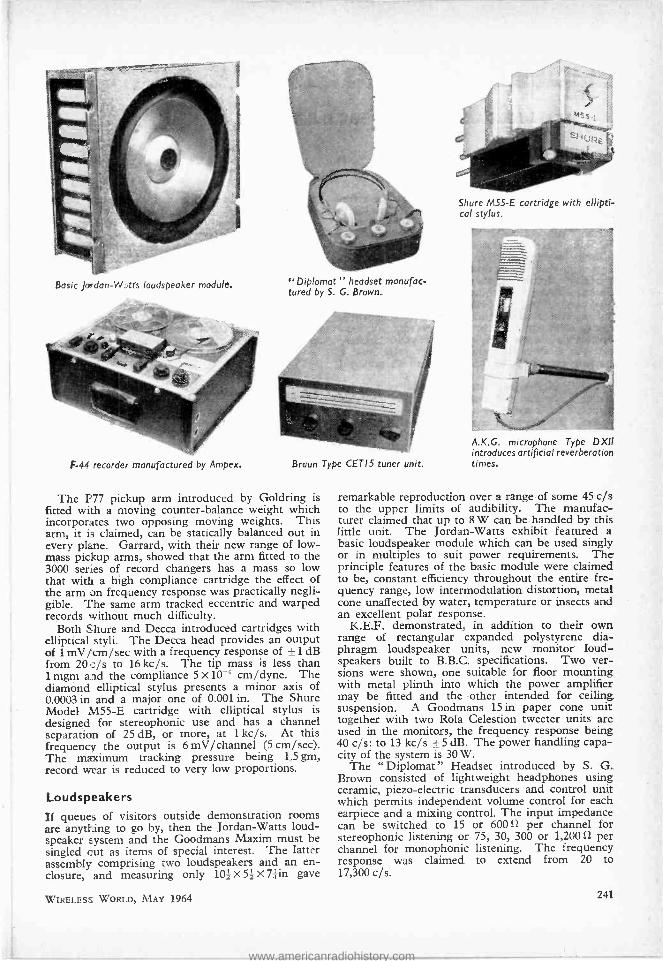
Basic Jordan -W ;ts loudspeaker module. "Diplomat " headset manufac- tured by S. G. Brown.
F -44 recorder manufactured by Ampex. Braun Type CETIS tuner unit.
The P77 pickup arm introduced by Goldring is fitted with a moving counter- balance weight which incorporates two opposing moving weights. This arm, it is claimed, can be statically balanced out in every plane. Garrard, with their new range of low - mass pickup arms, showed that the arm fitted to the 3000 series of record changers has a mass so low that with a high compliance cartridge the effect of the arm on frequency response was practically negli- gible. The same arm tracked eccentric and warped records without much difficulty.
Both Shure and Decca introduced cartridges with elliptical styli. The Decca head provides an output of 1 mV /cm /sec with a frequency response of ±1 dB from 20 c/s to 16 kc /s. The tip mass is less than 1 mgm and the compliance 5 x 10-s cm /dyne. The diamond elliptical stylus presents a minor axis of 0.0003 in and a major one of 0.001 in. The Shure Model M55 -E cartridge with elliptical stylus is designed for stereophonic use and has a channel separation of 25 dB, or more, at 1 kc /s. At this frequency the output is 6 mV/channel (5 cm /sec). The maximum tracking pressure being 1.5 gm, record wear is reduced to very low proportions.
Loudspeakers If queues of visitors outside demonstration rooms are anything to go by, then the Jordan -Watts loud- speaker system and the Goodmans Maxim must be singled cut as items of special interest. The latter assembly comprising two loudspeakers and an en- closure, and measuring only 101 X 52 X 7f in gave
WIRELESS WORLD, MAY 1964
Shure M55 -E cartridge with ellipti- cal stylus.
A.K.G. microphone Type DXII introduces artificial reverberation times.
remarkable reproduction over a range of some 45 c/s to the upper limits of audibility. The manufac- turer claimed that up to 8 W can be handled by this little unit. The Jordan -Watts exhibit featured a basic loudspeaker module which can be used singly or in multiples to suit power requirements. The principle features of the basic module were claimed to be, constant efficiency throughout the entire fre- quency range, low intermodulation distortion, metal cone unaffected by water, temperature or insects and an excellent polar response.
K.E.F. demonstrated, in addition to their own range of rectangular expanded polystyrene dia- phragm loudspeaker units, new monitor loud- speakers built to B.B.C. specifications. Two ver- sions were shown, one suitable for floor mounting with metal plinth into which the power amplifier may be fitted and the other intended for ceiling suspension. A Goodmans 15 in paper cone unit together with two Rola Celestion tweeter units are used in the monitors, the frequency response being 40 c /s: to 13 kc /s ±5 dB. The power handling capa- city of the system is 30 W.
The "Diplomat" Headset introduced by S. G. Brown consisted of lightweight headphones using ceramic, piezo -electric transducers and control unit which permits independent volume control for each earpiece and a mixing control. The input impedance can be switched to 15 or 600 per channel for stereophonic listening or 75, 30, 300 or 1,20012 per channel for monophonic listening. The frequency response was claimed to extend from 20 to 17,300 c /s.
241
www.americanradiohistory.com

Elements of Transistor Pulse Circuits S. -" ECCLES -JORDAN " BISTABLE MULTIVIBRATORS
By T. D. TOWERS* M.B.E.
ANUMEROLOGIST would look at the refer- ence " W. H. Eccles and F. W. Jordan, Radio Review, 1919, Volume 1, page 143 " and arrive
at the " magic number " 2 by repeatedly adding its digits together. But the reference has a more scientific connection with the numeral 2 than this. It was in this article that Eccles and Jordan first published details of their bistable multivibrator circuit, a 2 -stage switching device which has since become the " building brick " of many digital com- puters. Bistable multivibrators can be used to divide, count, store, or steer trains of pulses, and have become such a commonplace tool of pulse circuitry that the modern electronic engineer must have a working knowledge of the circuit and its principal properties.
The circuit has been used in many different engin- eering fields and has been given many different names. In this article we will call it just an " Eccles - Jordan," because most engineers recognize it under that name. It has also, however, been described in the literature as a " bistable," " bistable multi," " trigger," " binary ," " toggle," " scale -of- two," " BMV " and " flip- flip." Sometimes again, writers use the term " flip- flop," but purists prefer to reserve this last term for the monostable multi - iibrator described in a previous article in this series.
Eccles and Jordan gave the original circuit in 1919 in a valve version. As it happens, the transistor version works in much the same way basically as the valve one and we will deal exclusively with transistors here.
Basic Circuit of Eccles- Jordan In simplest terms, the Eccles -Jordan is a two- stage, common- emitter, d.c.- coupled amplifier with the output d.c.- coupled back to the input. The basic circuit, stripped of inessentials, is shown in Fig. 47(a) laid out as a conventional two -stage amplifier, with the forward signal going from left to right via RB2 and the feedback signal from right to left via RBi. In Fig. 47(b) it is redrawn in the symmetrical form normally used. This brings out clearly the hallmark of the Eccles -Jordan, the cross -coupling resistors from collectors to opposite bases. In practical circuits, these may be camouflaged by additional elements, but if you can trace an X- shaped pair of cross -coupling resistors in the circuit, it will usually be an Eccles -Jordan.
As its various alternative names imply, the Eccles - Jordan has two stable states. In each stable state, one of the two transistors is cut off and the other is held switched hard on (i.e. " bottomed " or " in saturation "). This .built -in circuit stability which keeps either transistor permanently switched on while the other is switched off, distinguishes the
*Newmarket Transistors Ltd.
bistable from the astable and monostable multi - vibrators discussed in previous articles.
We now have a circuit capable of remaining indefinitely in either of two stable states. To under- stand the switching action, suppose that in Fig. 47(b) the left hand transistor Ql is on (with its collector voltage close to the positive rail) and the right -hand one, Q2, is off (collector voltage close to negative rail). If we apply a positive -going pulse to the base of transistor Ql, it will cut off, and the voltage on its collector will move towards the negative rail and tend to drive Q2 on via the cross -coupling resis- tor, RB2. Once transistor Q1 comes out of saturation,
(a)
(b) Fig. 47. Eccles Jordan basic theoretical Circuit (a) Drawn as conventional amplifier (b) drawn as symmetrical circuit.
the circuit loop gain becomes large enough for regeneration to take control, and it switches rapidly over into the other stable condition with Ql off and Q2 on. Because of this regeneration, during the switching interval, the external " trigger " pulse need only initiate the switching action; the circuit will then carry the transition very rapidly through to completion on its own. We will deal more fully with triggering later below.
Basic D.C. Design The basic circuit used to illustrate the principle of the Eccles -Jordan in Fig. 47 could be made to work as it stands by careful selection of transistors, but in practical applications the circuit usually appears in the form of Fig. 48. Here a positive rail, V55,
242 WIRELESS WORLD, MAY 1964
www.americanradiohistory.com

Fig. 48. Basic practical power supplies.
has been added to ensure that the base of an " off " transistor is held positive with respect to its emitter. Also the circuit has been made symmetrical with equal collector resistances, etc.
The first point to be decided in the design is the output voltage swing required. The output can be taken from either collector, but conventionally it is usually shown taken (as in Fig. 48) from the right -hand transistor, Q2. Now when Q2 is cut off, its collector is approximately at the negative rail voltage, and when it is on, its collector is at zero volts. This therefore represents the available peak -to -peak voltage output swing. The designer therefore takes a negative supply voltage,
Vac = required peak to peak output voltage. Commercially available germanium transistors (which are at present the most commonly used in bistable multivibrators) tend to work most satisfactorily in the lower range of d.c. supply voltages. In practice, Voo will usually be found to be 6, 9, 12, or 18 volts, with a few designs going to 24 volts.
The next design point is the value of the collector current, Io, in the " on " transistor. In most general- purpose transistors, current gains tend to fall off below 1 mA and leakage current become significant compared with bias currents, and cannot be ignored even in an approximate analysis. Usually therefore, an " on " collector current of not less than 1 mA is designed for. On the other hand, the higher the " on " current, the greater the current drain from the d.c. supply. Other factors also affect the selection of the " on " current, but in practice it will be found that 10 usually lies below 10 mA. Thus
Io = 1 -10 mA. The selected design value of Io automatically
fixes the value of the collector resistor, Ito because when the transistor is on, the collector resistor is effectively connected from the negative rail to zero volts. To give an " on " current Io, we must take
Rc = Voo/Io The next circuit value that can be designed is the
collector -base cross -coupling resistor, RB. This must be low enough in value to ensure that the lowest -gain transistor used is fully switched on. If h,B m, is the lowest d.c. current gain at Io for the transistor type used, then a base current Io/hFE m,n is required to saturate the transistor. RB must be low enough to provide this base current together with the extra current diverted from the " on " base through RB' and also to give a margin against transistor current gain falling with time or low temperature. A common empirical rule is to take
Rs = 4hFE min R1.
circuit of Eccles Jordan
WIRELESS WORLD, MAY 1964
The base cut -off bias resistor, RB', and base supply voltage, VBB, can now be worked out. The resistor value must be such that when the transistor is off, its base is not less than half a volt positive with respect to its emitter. A common practice is to design for 1 V base cut -off (although with some diffused -base transistors precautions may be neces- sary here). When Ql is on, its collector is close to zero volts. The voltage at the base of the off tran- sistor, Q2, is then set by the potentiometer RB, RB' across VBB. For 1V cut -off, RB /(RB -I- RB' ) = 1/VBB, (1) and the current through RB is given approximately by 1/RB. Now, when Q2 is on, its base is close to zero volts, and current flowing down RB to VBB
diverts some of the current supplied to the base from Voo via Ro, RB. We have already selected RB to provide double the necessary current to saturate Q2, so that up to 1 /3rd of the current through RB may be safely diverted away from the " on " base through RB', without bringing Q2 out of saturation. To provide a margin we assume that only about 1/5 of the available current at the base is diverted through RB'. We therefore take VBB/RB' = t(Voo/RB), and substituting from (1) arrive at the design formulae:
VBB = Voo/(Vco - 5), and RB' = 5RB /(Voo - 5)
In Fig. 48, separate positive and negative supplies with a common earth return have been used. In practice it is sometimes more convenient to use a single supply, and this is achieved by a circuit of the type shown in Fig. 49. In this, either Ql or Q2 is switched on during the stable states and the collector current, Io, flowing through Rs, sets up a constant negative potential at the common emitters. The d.c. design of the single- power- supply circuit can be derived from that of the double -power- supply circuit of Fig. 48, because they are the same circuits with Va = Voo VBB and RE = VBB/Io.
The capacitor Ca shown dotted across RB in Fig. 49 is optional. It ensures that the d.c. conditions are not materially affected by the switching transients occurring across RE, but often it is dispensed with. A theoretical formula for CE can be derived showing its dependence on the transient switching times, but a convenient practical rule is to make
where fh, s the minimum common -base cut -off frequency in the transistor type used.
Both the circuits in Fig. 48 and 49 are saturated switching circuits; i.e. one transistor is switched hard on in the stable state. This has the drawback that a saturated transistor takes longer to switch off than
o VS
Fig. 49. Single- power -supply Eccles- Jordan Circuit.
243
www.americanradiohistory.com
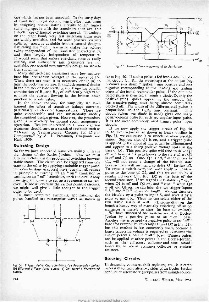
one which has not been saturated. In the early days of transistor circuit design, much effort was spent in designing non- saturating circuits to get higher switching speeds with the transistors then available (which were of limited switching speed). Nowadays, on the other hand, very fast switching transistors are widely available, and for most practical circuits sufficient speed is available from saturated designs. Saturating the " on " transistor makes the voltage swing independent of the transistor characteristics, and thus largely independent of temperature. It would seem that unless switching time is really critical, and sufficiently fast transistors are not available, one should now normally design for satura- tion switching.
Many diffused -base transistors have low emitter - base bias breakdown voltages of the order of 1V. When these are used it is necessary either (a) to limit the back -bias voltage, (b) include external diodes in the emitter or base leads, or (a) design the parallel combination of RB and RB', of sufficiently high value to limit the current flowing in the broken down junction to a safe value.
In the above analysis, for simplicity we have ignored the effect of transistor leakage currents, particularly at elevated temperatures. These are quite considerable and can substantially modify the simplified design given. However, the procedure given is satisfactory for normal room temperature operation. Readers interested in a more rigorous treatment should turn to a standard textbook such as " Design of Transistorised Circuits for Digital Computers," by A. I. Pressman, Chapman and Hall, 1959.
Switching Design So far we have concerned ourselves mainly with the d.c. design of the Eccles -Jordan. Now we must look more closely at the problem of switching between stable states. The circuit can be triggered from one state to the other by applying a suitable trigger pulse. This can be done in several ways, but they all reduce in principle to turning off an " on " transistor or turning on an " off " transistor, until the circuit loop gain rises sufficiently to set up a regenerative switch - over. Before we examine the various possible circuits, we might well give a little thought to the trigger pulse to be used.
In - most computer switching applications, the pulses handled are rectangular waves as shown at
a)
Fig. 50. Trigger Pulse Characteristics (a) Rectangular pulses (b) Bilateral differentiated pulses (c) Unilateral differentiated pulses.
244
Fig. 51. Turn -off base triggering of Eccles- Jordan.
(a) in Fig. 50. If such a pulse is fed into a differentiat- ing circuit CD, RD, the waveshape at the output (b), becomes two sharp " spikes," one positive and one negative corresponding to the leading and trailing edges of the initial rectangular pulse. If the differen- dated pulse is then fed through a diode, D, only the positive -going spikes appear at the output, (c), the negative -going ones being almost completely blocked off. The width of the differentiated pulses is proportional to the CDRD time constant. This circuit (when the diode is used) gives one sharp positive -going pulse for each rectangular input pulse. It is the most commonly used trigger pulse input circuit.
If we now apply the trigger circuit of Fig. 50 to an Eccles -Jordan as shown in heavy outline in Fig. 51, we can cause it to switch between bistable states. Suppose that Ql is on, and a trigger pulse is applied to the input of CD it will be differentiated and appear as a sharp positive voltage spike at the base of Ql. This positive spike will tend to drive Ql off and to initiate a switch -over to the state where Ql is off and Q2 on. Once Ql is off, further pulses to CD, will not cause a change of the bistable state because they will just tend to drive Q1 farther off. To cause a switch -over, we must apply a positive pulse to the base of Q2, and this we can do by a similar network CD,, RD,, D2 to the base of the second transistor. If we regard the bistable as " set " when Ql is off and Q2 on, and " reset " when Q2 is off and Q1 on, we can label the two trigger inputs " S " and " R " correspondingly. We can then set the bistable by a pulse to input S, and reset it by a pulse to input R. Thus we can select either of the two stable states at will. (Incidentally, on the bench a handy way of manually switching off an on transistor is merely to short its base to emitter).
We have illustrated the switch -over of an Eccles- Jordan by a positive pulse to an " on " base. Another way is to apply a negative pulse to an " off" base (for example by reversing D1 and D2 in Fig. 51), but this method is less commonly used, because a larger triggering voltage is required to overcome the cut -off potential on the " off " base. Trigger pulses can be applied at other points in the Eccles -Jordan, such as the collector, collector -and -base simul- taneously, or across common collector or emitter resistors.
Steering Circuits In designing counters, shift registers, etc., is it often necessary to make alternate sides of an Eccles -Jordan conduct on alternate trigger pulses from a single source.
WIRELESS WORLD, MAY 1964
www.americanradiohistory.com

(a)
(b)
RD2
(c)
Fig. 52. Trigger "steering " circuits a) Base triggering (b) Collector triggering (c) Hybrid trigger ng.
There are many " steering " circuits to achieve this. The more common of these are illustrated in Fig. 52. In all these trigger circuits, when a pulse arrives it finds one transistor off and one on, and one diode blocked off so that the pulse is directed or steered through the other diode to switch the Eccles -Jordan over. The next pulse finds the positions reversed and switches the circuit back again. In practical circuits, the trigger load resistor, RD, RD, and RD, in Fig. 52, will often be found replaced by diodes (connected as shown dotted) to speed up the re- covery time of the steering circuit between pulses. The selection of the trigger circuit capacitances and resistances, CD and RD, requires some thought, to ensure that sufficient drive power is obtained to switch the Eccles -Jordan, while ensuring that the recovery time of the differentiator is not so long as to limit the triggering repetition rate unduly. A detailed analysis of trigger circuits is beyond the ambit of this article, but some useful generalizations can be made. A fairly common rule is to make RD approxi- mately equal to the collector to base cross -coupling resistance. The value of CD should then be selected so that the CDR, time constant is less than the re- petition time of the train of pulses being steered. It should be kept as large as practicable, so that the trigger pulse does not cease before the Eccles -Jordan has begun to switch over. A useful rule is to start with CDR, equal to one -fifth of the shortest pulse repetition time and then adjust by cut -and -try methods to ensure both satisfactory triggering and resolution time.
WIRELESS WORLD, MAY 1964
Speed Limitations of Eccles- Jordan The switching speed of the basic Eccles -Jordan circuits so far described will be severely limited without some form of capacitor compensation. In practice, Eccles -Jordans normally incorporate small capacitors shunting the collector -base cross - coupling resistOrs. These " speed up " or " com- mutating " capacitors (CB in Fig. 53) improve the loop gain of the circuit at high frequencies and cause faster switching between bistable states. The C.R. combination may be considered as a compensated attenuator in conjunction with the parallel input resistance and capacitance of the tran- sistor, rb'e, and Cb'e, which passes a square wave with- out distortion. The theoretical design of speed -up capacitors is complex and a complete switching time calculation is seldom worth while, because of the numerous time constants involved and because the results depend strongly on the trigger wave -shape and amplitude. Most frequently, designers start from a " guesstimated " value of C and adjust empirically. One starting point sometimes used is to make
CB = hfe /(6fhfbRB) In connection with the triggering of an Eccles.
Jordan, it is of interest to estimate the maximum theoretical repetition rate at which the circuit can be triggered. It has been shown (J. J. Suran and F. A. Reibert, " Two -terminal Analysis and Syn- thesis of Junction Transistor Multivibrators ", Proc. I.R.E., March, 1956) that the maximum frequency of a multivibrator is fhfb /(hfe)* permitting a maximum pulse driving rate of twice this figure. This formula neglects the effect of the transistor collector capacitance on the recovery time of any cross- coupling networks, and in practice it is found that Eccles- Jordans can be triggered reliably up to about 1 /3rd of the theoretical limiting frequency i.e. up to 2fhfb/3(hfe) *. Although by no means exact, this gives a useful indication of what speed we can expect to use a particular transistor up to. For an audio transistor with a typical fhfb = 1 Mc /s and a typical hfe = 100, a maximum pulse repetition rate limit of about 66 kc /s is indicated. A 10 Mc /s r.f. alloy transistor with life = 100 could operate up to about 660 kc /s without much difficulty.
One interesting point arising from the last pares graph is that the maximum switching repetition rate varies inversely as the square root of the low frequency current gain of the transistor, which sug- gests that low- frequency, very- high -gain transistors are the least advantageous to use in any applications.
Returning to the trigger input circuit, the lower limit of trigger power requirements can be deter- mined by calculating the base charge in the transistor required to maintain the collector current when it is on. The trigger source must be capable of neutral-
Fig. 53 " Speed -up " or " commutating " capacitors.
CB CB
Rc
245
www.americanradiohistory.com

izing this charge in order to turn off the transistor. It can be shown that the "base charge for a just saturated transistor is approximately Ic /fhfb This suggests that the least trigger power is required when we use high frequency transistors at low " on " currents. Consequently if the trigger power is critical, it is often advantageous to use high speed transistors in slow speed circuitry.
Practical Examples of Eccles- Jordan Bistables To put values to some of the design features discussed above, we now give two typical practical Eccles- Jordans with pulse repetition rates up to 10 kc /s and I Mc /s.
Fig. 54 gives the circuit of an economical Eccles-
TRIGGER
INPUT
820
2.2k 2.2k
o02µ
~ÌGGER OUTPUT
TO NEXT DIVIDER
OUTPUT
10V
10k
+2V Fig. 54. Typical low -frequency (below 10kc /s) economical Eccles- Jordan used as divider in electronic organs.
Jordan of the type widely used in the divider circuits of electronic organs. One interesting point is that the circuit can switch satisfactorily at the frequencies (below 10kc,'s) normally handled, and yet does not use costly steering diodes. The trigger input pulse is taken via a .002 capacitor from one collector of the previous divider and applied across an 820 ohm common collector resistor. A signal output at half the frequency of the input pulses is taken from the left -hand transistor collector and trigger pulses at the same half -frequency are passed on from the right - hand collector to the 'text divider. The type NKT 225 used in the practical circuit are medium -gain audio transistors in TO5 encapsulations specially designed for direct printed circuit board mounting, which make possible very small boards suitable for modular assembly of an organ.
In Fig. 55, we have the circuit of a "conventional" computer Eccles -Jordan capable of working up to a counting speed of Mc /s reliably. The trigger differentiating circuit uses a diode D1 instead of the conventional resistive load as this improves the rear flank of the trigger pulses, and so makes possible a higher switching rate. The trigger steering is conventional base cut -off via the diodes D2 and D3. The NKT 127 transistors are germanium alloy devices with a minimum frequency- cut -off of 15 Mc /s.
Conclusion In this article, we have attempted to give a working insight into the Eccles -Jordan bistable multivibrator.
246
330p
o-1 TRIGGER
INPUT
NKT NKT 127 127 OUTPUT
Fig. 55. Conventional .Mc /s Eccles- Jordan computer bistable.
Specific applications of this type of circuit will be given in later articles in this series, but before we leave the subject, a word of warning is necessary. Sometimes an Eccles -Jordan will be erratic in spite of everything seemingly being correctly designed. One of the most insidious causes of erratic operation is an over -sensitive circuit. For example, it is possible for the circuit to be so sensitive that it switches not just the way it is intended but it also switches back spuriously on a single pulse. It may not lock out after switching on the front of a single pulse, but detect the tail of the pulse as an additional trigger signal. At the time of writing this article, the author came across a curious case where an Eccles Jordan would operate happily at 30 kc /s and continue to work down to a few pulses a second if the frequency was turned down steadily. But, if an attempt was made to trigger the circuit directly at slow speed without starting at the higher, it ceased to work. No explanation of this apparent hysteresis has been reached yet, but when you are working with Eccles - Jordans one must always be prepared to find " hysterical " operation such as this which may not be easy to eliminate.
INFORMATION SERVICE FOR PROFESSIONAL READERS
To expedite requests for further information on products appearing in the editorial and advertisement pages of Wireless World each month, a sheet of reader service cards is included in this issue. The cards will be found between advertisement pages 16 and 19.
We invite readers to make use of these cards for all inquiries dealing with specific products. Many editorial items and all advertisements are coded with a number, prefixed by 8WW, and it is then necessary only to enter the number(s) on the card.
Readers will appreciate the advantage of being able to fold out the sheet of cards, enabling them to make entries while studying the editorial and adver- tisement pages.
Postage is free in the U.K., but cards must be stamped if posted overseas. This service will enable professional readers to obtain the additional informa- tion they require quickly and easily.
1......
WIRELESS WORLD, MAY 1964
www.americanradiohistory.com

LETTERS TO THE EDITOR
The Editor does not necessarily endorse opinions expressed by his correspondents
Walkie Talkies I AM most concerned that considerable numbers of cheap 27Mc /s band Walkie Talkies are flooding the radio retail and wholesale trade without the fact being clearly pointed out to would -be purchasers that no fre- quency allocation is available in this country in the 27 Mc /s band for the operation of these equigfnents and as a consequence the British Post Office wTll not issue a transmitting and receiving licence for this equip- ment. Anyone purchasing this equipment and operat- ing it will therefore be breaking the law and liable for prosecution.
Questions were asked in the House of Commons by Capt. L. P. S. Orr, M.P., and the above statements were confirmed by the Postmaster General on that occasion. Retailers and wholesalers are apparently not aware of this fact.
A further question was asked why this class of equip- ment can be imported into Great Britain from Japan and America when it clearly cannot be legally used in this country. No action appears, however, to be planned and I Feel that the radio trade must take a stand to ensure that this equipment is not imported and sold to the public when the purchasers cannot legally use it.
Baldock, Herts. W. K. STEVENSON [Some of thé transmitter /receivers advertised in this journal,
which would not qualify for a licence in the U.K., might well be bought by customers overseas for use in other countries in which
this journal circulates. The situation in the U.K. has recently been clarified by a
statement from the G.P.O. which is here appended. -Ed.] " Walkie- Talkies. Any use of radio communication in the United Kingdom must be licensed by the Postmaster General and the Post Office has recently conducted successful prosecutions for the unlicensed use of " walkie- talkie" radio equipment operating on fre- quencies around 27.12 Mc /s. It may not be generally known that the Postmaster General will not license the transmission of speech on these frequencies as the band has been designed for industrial, scientific and medical use.
Transistorized transmitter /receivers are also available working on slightly higher frequencies, e.g., 28.5 Mc /s but this frequency falls in one of the bands assigned for use by licensed radio amateurs. Before an Amateur Licence is granted the applicant has to pass the Radio Amateur (Technical) Examination and the Post Office 12 words per minute Morse sending and receiving test.
Dealers would therefore be well advised to bear in mind, when offered " walkie- talkie " equipment using a frequency of 27.12 Mc /s or thereabouts, that the Post Office will not issue licences to purchasers of this equip- ment, and any use, including that for demonstration purposes without a licence would be contrary to the law. Furthermore, equipment operated by licensed amateurs in the 28.0 -29.7 Mc /s band must be capable of operating within the terms of the Amateur (Sound) Licence -for example, a satisfactory method of fre- quency stabilization must be employed in the sending apparatus and frequency measuring equipment must be provided capable of verifying that the sending apparatus operates within the frequency band of 28.0 -29.7 Mc /s.
Facilities are available for private mobile radio services using speech in the 80, 160, 170 and 460 Mc /s bands and suitable equipment which conforms to the relevant Post Office specification can be obtained through the trade.
WIRELESS WORLD, MAY 1964
It is also worth mentioning that most of the ex- Service mobile radio equipment on the market operates on fre- quencies not available for private mobile radio services in the United Kingdom, and could not be adapted to operate satisfactorily within the narrow v.h.f. Channel available. The use of such equipment is, therefore, not permitted by the Post Office on private mobile radio services."
London, GENERAL POST OFFICE, CENtral 1170. March, 1964.
" Groove Deformation in Gramophone Records" IT used to be said that a poor workman blames his tools. This does not, however, contradict the fact that a good workman may be handicapped by inappropriate tools, and I feel that Mr. Barlow is somewhat handi- capped by this same fact. The optical photographs in his article in the April issue are too small to give properly informative assessments of what has happened to the record surface and his claim that a grease smear rubbed on with a finger gives a 1000 °A thick layer could be a possibly precarious procedure.
In view of this and of the clear electron micrographs published in Wireless World, August 1961 and April 1963, it is hard to see how Mr. Barlow can talk about the evidence offered in support of claims to a 3 -gram pickup to track within the elastic limit as being " unreliable, in- correct or non -existent ".
To emphasize this point I here submit (a further part of the evidence that was not published in the above articles) part of a X 7000 electron micrograph of the result of 4 grams once on 0.0006 in stylus on the inside diameter of the ungrooved record surface at 33; r.p.m. This picture should be compared with Mr. Barlow's Fig. 7 for the appropriateness of " the tool " to measurements of such magnitudes. The electron picture also shows that even sub -microscopic blemishes on the top of the surface are still not obliterated (a motor car bearing is also better when run -in).
Mr. Barlow quotes his measurements of surface elastic limit at } gram on 0.001 in. He continues to relate stylus forces to width of indent, though what real significance this can have for the gramophone record user is still obscure to me since pickups are sensitive to deviations normal to the plane of the groove, not to areas of contact. I showed both a theoretical and experimental basis for this in Wireless World, July 1961. Mr. Barlow fails to do either. This confounds his computation of tracking weight in relation to stylus radius.
I do not, however, by any means claim the last word on this (or other) measurements. On the contrary the above articles were, as stated therein, published as a "pointer" to further work.
Talking of the surfboard effect, Mr. Barlow says there is no dramatic reduction in track width under dyna- mic conditions and decries its action with a misunder- stood reference to block and plane, and reliance on the naked eye. The lift, of course, is in spite of the friction between block and plane and is proportional to the tangent of the horizontal force.
However, the important difference between our approaches is contained in whether the " elastic limit " shall be considered as an academic nicety or as something of real value to record users. Mr. Barlow of course is very much concerned with sub- surface yielding and accordingly says that the elastic limit is exceeded by
247
www.americanradiohistory.com
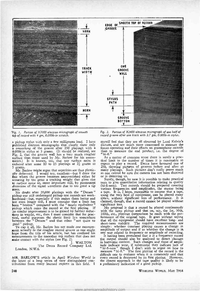
EDGE OF SMOOTH TOP OF RECORD
,GROOVE
'Fig. I. Portion of X7000 electron micrograph of smooth top of record with 4 gm, 0.0006 -in scratch.
a pickup stylus with only a few milligrams load. I have published electron micrographs that clearly show only a smoothing of the groove after 250 playings with a 0.0006 in stylus at 3 grams. (It should be realized, see Fig. 2, that the groove wall has a very much rougher surface than those used by Mr. Barlow for his assess- ments.) It is known, too, that any surface noise is reduced after some 10 to 15 playings at 21 grams to 5 grams.
Mr. Barlow might argue that asperities are thus plastic - silly deformed. I would say, excellent -but I draw the Ene where the groove becomes impoverished either by scouring by too great a tracking weight that gives rise to surface noise or, more important still, by permanent distortion of the signal waveform due to too great a tip mass.
No doubt after 20,000 playings with the " Deram " pickup our still undamaged pickup test records are work - hardened -but, especially if this makes them better and last even longer still, I must consider that a limit has been " broken " compared with the " nearly equivalent" pickup which ruins the record at the first playing. If no similar improvement is to be gained by further reduc- tions in weight, etc., then I must consider that for prac- tical, useful purposes the elastic limit lies somewhere between the " Deram " and that other " not quite so good " pickup.
To cap it all, Mr. Barlow has not made one measure- ment actually in the rougher record groove as one might hope from the title of his article, but has confined his measurements to the smoother top surface that does not snake contact with the stylus (see Fig. 2).
J. WALTON The Decca Record Company Ltd.
London, N.W.6.
MR. BARLOW'S article in April Wireless World is the latest of a long series of very distinguished con- tributions from many learned experts in this field. I
248
Fig. 2. Portion of X2400 electron micrograph of one half of record groove after one track with 2.7 gm, 0.0006 -in stylus.
myself feel that they are all obsessed by Lord Kelvin's dictum, and are much more concerned to measure the forces operating and their effects on gramophone records than to measure the end product, i.e. the degree of "hi-fi."
As a matter of common sense there is surely a prac- tical limit to the number of times it is reasonable to expect to play a record. Decca have favoured one of 250, showing pictures of grooves before and after so many playings. Such pictures don't really prove much as one cannot be sure the camera has not been deceived or is deceiving us.
Surely, though, by now it is possible to make practical tests to give quantitative information relating to quality (hi -fi- ness). Test records should be prepared covering various frequencies and amplitudes, the master being a tape. It is, I hope, reasonable to assume that a tape, using the very best of equipment, can be played many times, without significant loss of performance. It is claimed, though, that a record cannot be played without significant loss.
My proposal is that a record be played continuously with the same pickup and that on, say, the 1st, 50th, 100th, etc., playings comparison be made with the per-. formance of:the original tape. It goes without saying that all the equipment should have excellent 'long- and short-term stability. The required measurements are simply: whether constant playing causes a change in amplitude of output and if so whether the change is in any way related to frequency or amplitude of recording.
It having been postulated that it is a frequency record the output should also be analysed to detect changes in harmonic content. Such changes and those of ampli- tude indicate wear, if substantial they indicate lack of " hi -fi -ness " though I don't wish to argue on how to measure " hi -fi." The first playing of the record is the difficult one to evaluate when it is commonly said that every record is destroyed by its first playing. However, the closest approach to the tape quality is likely to be a preliminary indication of a good pickup.
WIRELESS WORLD, MAY 1964
www.americanradiohistory.com

Who is going to do some practical testing instead of continuing in the rather sterile groove of seeking for - mulæ? It seems a very reasonable assumption that wear is the culmination of the operation of several non- linear forces and as such is unlikely ever to be expressed in mathematical terms. We have now many pickups of good aural quality operating with playing weights from J to 3 grams. Why not try comparative tests to measure wear? It should give a useful lead for future design though I suspect some current designs may, not withstanding Mr. Barlow's argument, be only slightly damaging to the record.
London, N.20. L. STREATFIELD The author replies:
Mr. Walton says in his letter that the important difference between our approaches to the problem of record deformation depends on the definition of " the elastic limit ". It does indeed. The elastic limit is a precisely defined concept and far from being an " academic nicety ", is of the greatest practical import- ance; every bridge, car, train, ship, large building, etc., is designed on the basis of an exact meaning of the term " elastic limit ". Mr. Walton is now shifting his ground by saying that the elastic limit is represented by a point where a certain standard of reproduction is reached. This is nothing but the abuse of words.
It should be obvious from reading the text of my article that the purpose of Fig. 7 was merely to show that the tracks referred to did exist and no measure- ments or surface details were needed. Fig. 11 at only X 57 magnification gives an idea of the scale used; higher magnifications were not needed, still less the very high powers of the electron microscope. The latter is most valuable but whether it will show up shallow tracks in the partly plastic range is uncertain.
Mr. Walton's Fig. 1 shows that a 0.0006 -in radius stylus, loaded with 4 gm. works well into the fully plastic range, yet he claims that a 0.0005 -in radius stylus with 3 gm. works within the elastic limit, even at extremes of amplitude + acceleration. His Fig. 2 shows very little effect on the groove, which conflicts with Fig. 10, August 1961 and Fig. 6, April 1963, when under similar loading, plastic deformation can be clearly seen on both groove walls, especially the unmodulated one. (The signal level in these cases is very far from the maximum.)
When relatively large surface irregularities are present, it would be expected that severe plastic deformation would not completely obliterate them. This is well known to anyone who has carried out a hardness test; although a hard polished indenter is pressed as much as several millimetres into the surface of the specimen, the surface must be fairly smooth if good clear polished impressions are to be obtained. Failure to obliterate surface marks does not mean that bulk plastic deforma- tion has not been produced; the presence of surface roughness merely makes accurate measurement more difficult.
The accuracy of the grease smear technique has been dealt with in the previous paper (7.A.E.S. October 1958); the consistency of the results may be judged from Fig. 4, p. 162, April issue of W.W. In the present tests, only the total track width at loads below 2.5 -3.5 gm. on 0.001 -in radius for one revolution are involved, and in any case, other techniques such as the use of vacuum vapour deposited metal films give the same results. It is curious that Mr. Walton should say that I lack suitable tools when his own tool, the " Talysurf " has in this context been shown to be of little value -hence the need for large scale tests.
Of surfboard action, which Mr. Walton now says is not due to friction, there is no component tending to reduce the deformation caused by the stylus; even if there were, it would only have an appreciable effect on the first playing and would operate also in the " static " condition.
In determining critical indenter loads, either width or depth of impression could be measured; width is more
WIRELESS WORLD, MAY 1964
useful and more accurately measurable. On the other hand, depth measurements must be made if a pickup is being designed to produce indentations not exceeding a certain depth, or distortion not exceeding a certain limit; this of course is nothing to do with the elastic limit.
In conclusion, it should be made clear that the pur- pose of my article was to describe, once and for all, what happens to the record material under the loads to which it is subjected, and not to decry any commercial product. Just how much deformation of the record can be tolerated before distortion becomes audible is another matter and might well be the subject of further work, as suggested by Mr. Streatfield.
D. A. BARLOW
B.B.C. Sound Broadcasting THE letter from the Head of B.B.C. Engineering Infor- mation in your January, 1964, issue is no doubt intended to be a refutation of Mr. Hodgson's criticisms and many others of a similar kind made in recent years.
The sad fact is that this reply is a confirmation of all that many of us feared and presents the timid and even torpid engineering policies of the B.B.C. in sound broadcasting as if these were the inevitable corollary of some natural law.
Mr. Turner suggests that the limited bandwidth on land -lines, which determine the programme quality over much of the country, is justifiable because: (a) this is what the G.P.O. offers the B.B.C., (b) other countries are no better, (c) most listeners would be unable to tell the difference if the range were extended from 10 kc /s to, say, 15 kc /s.
Of course, the G.P.O. will manifestly provide what- ever the B.B.C. is prepared to pay for, and the prob- lem is specially relevant to this country because of the highly centralized origin of most of the programme material.
Millions of listeners to gramophone records have bought special equipment to avail themselves of the extra quality offered by the modern record, much of this equipment being quite expensive and relatively difficult to handle domestically; in other words, given the chance the customer is quite prepared to go to con- siderable lengths to obtain good quality reproduction.
Mr. Turner excuses a land -line policy which does not appear to have changed in 25 years, by citing the formid- able cost of effecting any improvement; he states that " this cost could only be met by reducing expenditure elsewhere " and that some leeway has still to be made in the coverage of v.h.f. services. However, the 1964 Year Book boasts (page 18) that " nearly 99' of the popula- tion is within reach of v.h.f." How near to 100% have we to be before any other technical improvement can be effected? Furthermore, if we examine the 1962/63 B.B.C. Revenue Account we find that the pro- portion devoted to " S.B. and Intercommunication Lines " is only 2.17 % of the whole, so that any cost of improvement would represent only a very small pro- portion of this total revenue.
Turning now to stereo broadcasting, the B.B.C. con- tribution has so far been negligible, amounting to only 30 minutes per week, at unsuitable times, on the wrong channels. This minimal effort compares very unfavour- ably with the imagination and enthusiasm shown, for example, by R.T.F. in France, who have participated actively in stereo demonstrations at exhibitions and have broadcast in stereo such works as " Les Perses," while of course in the U.S.A. there are already at least 96 f.m. /stereo broadcast stations.
However, this technical tardiness and complacency is confined only to the sphere of sound broadcasting. If we look at the B.B.C. initiative and effort in the tele- vision field we are in an entirely different world. The B.B.C. is about to introduce the 625 -line TV service with the implied promise of a vastly improved technical standard although the highly experienced editor of Wireless World stated categorically of a demonstration
249
www.americanradiohistory.com
that " we could detect no difference between 405, 625 and 819 lines. "t (No problem of measuring increased cost against marginal improvement here!) The Cor- poration also boasts of the vast amount of research and development done in colour TV; although few viewers in America or elsewhere have been persuaded to lay down hard cash for this amenity.
Above all, it is the air of impervious sanctimony which pervades the B.B.C. pronouncements which is so daunting. Let me quote again from the Year Book which states that " as early as 1950 the B.B.C. began a series of experimental high -power transmissions on very high frequencies (v.h.f.) " as if in some way this typified the prevision and technical acumen of the Cor- poration. " As early as 1950 " there were already 700 working v.h.f. /f.m. stations in the U.S.A., while in the following years the Continental authorities rapidly out- stripped the B.B.C.
In the light of previous experience it is only too easy to predict the next stages in this sorry story of f.m./ stereo broadcasting:
(i) A long period of study and experimentation to elicit data already well known.
(ii) A final decision which is already a foregone con- clusion (there is in fact no particular reason why an internationally compatible standard need be adopted for a broadcasting system of restricted range).
(iii) A deferment of a decision to proceed, because by then the B.B.C. resources will already be committed to 625 /colour TV conversion.
With some justification the Corporation pleads that it aims to lead public opinion in cultural matters; let it extend the same initiative to the technical field; thus in the Year Book one finds that : "The stated policy of B.B.C. Sound Broadcasting is to serve minorities as well as majorities, making every effort to provide the best at all levels of taste and interest."
Readers of the 1964 Year Book were no doubt cheered to learn that, from the limited sums available for stereo broadcasting, the B.B.C. was able to divert cash to " broadcast works specially compiled for stereophony," including a jazz opera!
I am sure that the B.B.C. would hate its well -wishers to think that it is only capable of decisive action if a commercjal rival is breathing down its neck.
Virginia Water, Surrey E. JEFFERY t . at a distance of 12ft.... For the remaining context
see p. 299, July, 1962. -ED.
Torsion -wire Pickup Arm Suspension
I WOULD like to make a few comments on the tor- sion -wire suspension idea described by J. K. Murray in the March issue.
The first is to query the statement that providing an arm with a counterweight " doubles the inertia of the moving system." The most important inertia to consider is the total effective head inertia and it would be a very ungainly and poorly designed arm where total head intertia were doubled by the addition of a counter - weight-an increase of about 30% would be a fairer estimate.
The statement -that if the arm " could be dynamic- ally balanced in all planes " (i.e., presumably, suspended with its c.g. at the intersection of the two suspension axes) "then acceleration due to shocks from any direction would cause no relative movement between head and groove " -is a little misleading. Provided that centre of suspension of the arm has a relatively rigid connec- tion through to the turntable the above would be true, but only for shocks which cause a linear movement of the player (i.e., movement in which all parts of the player more with identical motions). Shocks causing some tilt or rotation in the player can result in pivot and turntable moving with different motions and hence causing a relative movement between head and groove.
As mentioned above, one of the requirements for stability to linear player movements is that the positions of the centres of suspension of arm and turntable should
250
be rigidly fixed in relation to one another, but the sus- pension of the arm on its torsion wire would not seem likely to provide this unless the wire was under extreme tension. If the latter were the cause there still remains a possible criticism in that the vertical " pivot " reson- ance is likely to be fairly low in frequency and of high Q -thus head response may be affected. Also, if this resonance happens to fall at a rumble frequency, an increase in rumble is likely. The presence of the grease specified around the wire would tend to damp pivot resonances but since the mass involved is Iarge while the viscous drag on the wire is relatively small, little damp- ing seems likely.
Concerning the cancellation of variations in tracking weight due to large warps; the cancelling force due to the loading of the torsion wire is dependent upon the amplitude of the warps whereas the actual variation in tracking weight due to movement of the head is depen- dent upon the acceleration. Since warps of the same amplitude can produce accelerations over a wide range, perfect cancellation cannot even be approached and it seems debatable whether it is worth while attempting it.
Harking back to the conditions for complete stability to linear player movements, these entail a complication in design, e.g., the addition of a spring, etc., to provide the necessary tracking weight. Since, probably under most playing conditions, shocks to the player cause a slight tilting movement, instability will still be likely even with this complication. With a conventional arm and counterweight in which tracking weight is set by shifting the counterweight along the arm, stability to linear player movements will be quite good and the stability to the player movements usually encountered will probably be only marginally less than with an arm designed for complete stability. This again raises the question -" Is the complication worth- while? "
Finally, in fairness to Mr. Murray's idea, provided the "pivot" resonances can be placed high enough in frequency and controlled, it does seem to offer a neater and simpler arrangement than the conventional method of achieving the same aims (i.e., separate vertical and horizontal bearings with a spring to get the tracking weight), and therefore well worth trying. However, since Mr. Murray's practical details are rather skimpy and may leave experimenters scratching their heads if any of the aforegoing forebodings prove true, maybe the fol- lowing would help.
The variation in tracking weight given by the torsion wire for a given warp amplitude will depend upon wire diameter and tension, and it is suggested it may be best to use as fine a wire as possible under high tension to keep the " pivot " resonances relatively high while keeping the above variation within bounds. I would hazard a guess that provided the vertical pivot resonance is kept above 50 c/s then no noticeable deterioration in stability to linear player movements would result. To well damp the pivot resonances the use of a much thicker grease around the wire is also suggested.
Appleby. J. BICKERSTAFFE
The author replies: Mr. Bickerstaffe's remarks concerning my statement
that the use of a counterweight doubles the inertia are quite valid. The inertia would be doubled only if the head and counterweight were of equal mass, mounted at equal distances on either side of the pivot. In all nor- mal arms the counterweight is of much greater mass than the head, and is mounted as close as possible to the pivot. This does not double the inertia and I would like to eat my rashly written words with due humility!
Shocks which introduce a rotational component to the record player about the axis of one of the arm pivots would obviously produce a flywheel effect and might well cause groove jumping. This, surely, is the obvious exception to shock immunity where the system " almost, if not entirely, meets . ideal requirements." I was talking about linear shocks and I am sure that most readers will have appreciated this fact.
Torsion wire tension and resonance. Yes, the torsion
WIRELESS WORLD, MAY 1964
www.americanradiohistory.com

wire is under a fair degree of tension but I would hardly describe it as " extreme " considering that piano wire is a high -tensile material made for such purposes. He will, no doubt, have noticed in Fig. 1 that tension adjust- ment nuts are provided for this purpose. The funda- mental resonance of the moving system is extremely low due to the relatively large masses involved; it is well below the audible range and does not increase turn- table rumble. Higher -order resonances along the length of the torsion wire are effectively damped by the sili- cone grease and the close proximity of the nylon bushes. MS4 silicone grease was specified because of its tem- perature stability, and it produces adequate damping despite Mr. Bickerstaffe's misgivings!
Although the comments regarding the amplitude and acceleration produced by warped records are correct, the range of acceleration is not as wide as Mr. Bickerstaffe would have us believe -unless he plays 78 r.p.m. records with his stereo pickup. The range of amplitude is quite wide. I never claimed to "approach perfect cancella- tion": in fact, I described the increase of tracking weight as a "compromise solution" but it is most effec- tive when put to the test.
With a conventionally mounted pickup arm there will be an out -of -balance mass equal to the tracking weight if a counterweight is used -considerably more if spring counterbalancing is used.
The most common form of shock is due to somebody jumping on a springy floor, or to a heavy door slam- ming. Both forms of shock are very nearly linear in direction and a perfectly balanced system gives a con- siderable improvement in shock immunity.
No doubt some people will follow Mr. Bickerstaffe's constructional advice and may obtain excellent results -he may have constructed his own arm along these
lines by now. When I wrote the article I had already found, by practical experience, that 21 or 22 s.w.g. wire and MS4 grease gave good results in the tubes and bushes described in my article; further experiment is always to be encouraged but I don't guarantee the results!
JOHN K. MURRAY
Stereo Pickup Terminating Impedance
IN the " Transistor High- quality Pre -amplifier " des- cribed by E. Carter and P. Tharma in your August 1963 issue, the authors use a low- resistance termination for magnetic pickups so that in conjunction with the pick- up's inductance the required h.f. attenuation takes place.
In the case of the Decca "ffss" pickup, however, the effective resistance of the pickup itself increases at high frequencies to an extent which prevents the full attenua- tion from being obtained by this method.
Moreover, even if the attenuation is supplemented elsewhere, the proposed termination of a few thousand ohms would seriously impair stereo separation, especi- ally at high frequencies. We have always recommended about 47 k12.
This pickup works with vertical and lateral sensing elements and the stereo signals are the sum and the difference of the vertical and lateral outputs, obtained by interconnecting the coils. For proper stereo separa- tion the vertical and lateral sensitivities, in terms of voltage output, must be equal, but for reasons of practi- cal design their impedances are not. If, therefore, the stereo outputs are terminated with too low an impedance the equality of sensitivity is upset and separation suffers.
London, N.W.6. D. G. JAQUESS The Decca Record Company Ltd.
COMMERCIAL LITERATURE Standard Telephones & Cables Ltd. has produced a
36 -page " Ministac Manual" describing the various ways that S.T.C. Ministac modules can be used to accommodate complete circuits of standard components. Copies are available from the S.T.C. Semiconductor Division (Rectifiers), Edinburgh Way, Harlow, Essex. 8WW 329 for further details
The 1964 Muirhead catalogue describing their facsi- mile communication systems, precision electrical instruments, synchros and servo systems, is obtainable from the company's offices in Beckenham, Kent. The text of the catalogue is given in English, French and German. 8WW 330 for further details
A catalogue describing the " Jetlite " range of light- weight headphones (5oz) and headsets (6oz) manufac- tured by Amplivox Ltd. is available from the company's works in Beresford Avenue, Wembley, Middx. Noise - cancelling magnetic and carbon microphones are avail- able for the headsets. 8WW 331 for further details
A brief description of the range of harbour radar equipment produced by Decca Radar Ltd., 9 Albert Embankment, London, S.E.1, is included in a brochure entitled " Decca Harbour Radar." The factors effecting the choice of suitable equipment and the siting of the installation are considered in this 24 -page publication. 8WW 332 for further details
Advance technical data sheets AT.1 to AT.4, describ- ing a new range of standardized a.f. power transformers, are being issued by Gardners Transformers Ltd. as a supplement to their audio transformer amplifier leaflet GT.4. Copies can be obtained from the company's works in Somerford, Christchurch, Hants. 8WW 333 for further details
WIRELESS WORLD, MAY 1964
Equipment wires coated with polytetrafluoroethylene and fluoroethylenepropylene are described in B.I.C.C.'s 8 -page publication No. 475, and polyurethane -based enamel -insulated, self -fluxing winding wires for high- speed winding of coils are included in publication No. 474. Copies are obtainable from British Insulated Callender's Cables Ltd., 21 Bloomsbury Street, London, W.C.1. 8WW 334 for further details
RCA Application Note SMA -21 entitled " Character- ization of Second Breakdown in Silicon Power Tran- sistors," discusses the theory of this local thermal run -away effect, and practical considerations for safe working. Copies of SMA -21 may be obtained from Commercial Engineering, Electronic Components and Devices, Radio Corporation of America, Harrison, New Jersey, U.S.A. 8WW 335 for further details
An abridged catalogue covering the range of test and laboratory instruments manufactured by Advance Elec- tronics Ltd. is now available from the company's offices in Roebuck Road, Hainault, Ilford, Essex. Technical details are included for all instruments, and copies of the catalogue will shortly be available with French and German translations. 8WW 336 for further details
A leaflet (No. 101) describing metal oxide resistors is now obtainable from Electrosil Ltd., Pallion, Sunder- land, Co. Durham. Semi - precision, high -stability and general purpose components are included in the leaflet. 8WW 337 for further details
A range of single and double control knobs for radio and electronic equipment applications is described in a recent catalogue from Barclay- Stuart (Plastics) Ltd., of Brunswick Street, Luton, Beds. 8WW 338 for further details
251
www.americanradiohistory.com

RECENT TECHNICAL DEVELOPMENTS
Micro- meteorite Detector One of the experiments mounted in the U.K.2 satellite is concerned with the measurement of the density of cosmic dust in space. Dr. Jennison of Manchester University designed, and Ferranti built, devices to detect and measure micro -meteorites. One of the detectors consists of an aluminium foil moving across a window transversely to the satellite's axis of. spin. In spite of their minute mass, the speed of the micro - meteorites (of the order of 106 m.p.h.) is sufficient to enable them to punch holes in the foil. Once every revolution of the satellite about its own axis, the sun shines through the holes and energizes a bank of solar cells behind the foil. The number of holes determines the density of the cosmic dust and the
Ferranti cosmic dust detector. Calibration holes are each side of the window.
amplitude of the pulses, which are compared with those caused by pre - punched standard holes, gives the size of the particles. The pulses are amplified and telemetered, and the foil is moved on after each revolu- tion.
" Rear Window" C.R.T. In radar reconnaissance operations, it is often necessary to photograph the cathode ray tube display. While this is being done, the display can- not be viewed and information can be lost. To avoid this, the Ameri- can firm of Sylvania Electric Pro- ducts have introduced the SC -3821 seven -inch tube with an optically flat window in the bulb. In this way, still or ciné films can be taken while the picture is being viewed. When photography is not required, the window can be used to project static information on to the tube face
252
Sylvania cathode -ray tube with window for photography.
to provide, for instance, a back- ground map with radar returns superimposed on it.
Medical Telemetry The normal type of medical tele- metry transmitter takes the form of an amplifier to increase the power of the signals produced by the body, a modulator and a transmitter. In the interests of compactness and light- ness, it is desirable to cut out one stage, and the Hampstead Labora- tories of the Medical Research Council have developed a frequency- modulated transmitter which is cap- able of being fully modulated by signals of the order of 1 mV without previous amplification. The voltage - sensitive junction capacitance of a silicon diode is used as the modulat- ing element in a 100 Mc /s oscillator which feeds a whip aerial through a buffer amplifier. At this frequency a modulator sensitivity of 30 kc /s /mV is obtained. Long -term a.f.c. is used in the receiver, which reduces the importance of the transmitter fre- quency stability, a chopper based on a small watch movement being used to modulate very low- frequency signals. In circumstances where three signals are obtained, one a d.c. level, one a rate and the other a phase, they can all be transmitted simultaneously.
U.H.F. Ultrasonic Transducers Two new types of ultrasonic trans- ducers using cadmium sulphide have been developed by Dr. N. F. Foster of Bell Telephone Laboratories. For operation at frequencies up to 1,000 Mc /s and bandwidths up to 200 Mc /s, one type is made by diffusing copper into conductive cadmium sulphide. " Trapping
sites " are provided for the conduc- tion electrons to obtain a high - resistivity surface region across which is developed the electric field. The other type is formed by depositing a film of cadmium sulphide up to 7 s
thick on material such as quartz which is suitable for the propagation of ultrasonic waves. The quartz is first coated with a conductive coat- ing, and after deposition of the cad- mium sulphide, another layer of copper is evaporated on. The film is subjected to heat treatment to recrystallize it, giving a high- resist- ance layer which acts as the trans- ducer. The performance is com- parable with the diffusion type, and both types avoid the problem of pre-. cision grinding to obtain specific frequencies.
Logic Design Kit The rubber stamp is not normally considered an essential part of the electronic engineer's equipment. The introduction of modular circuits in various forms has, however, made some form of rapid circuit deline- ation desirable, and SGS- Fairchild have introduced a kit consisting of a set of rubber stamps and a "loading chart." Each stamp bears the im- pression of one circuit of the SGS - Fairchild Micrologic elements, and the loading chart gives the rules for interconnection, so that a logic dia- gram may rapidly be converted into a circuit diagram. The kits are obtainable from SGS -Fairchild Ltd., 23 Stonefield Way, Ruislip, Middx.
Rubber -stamp logic design kit by SGS - Fairchild.
WIRELESS WORLD, MAY 1964
www.americanradiohistory.com
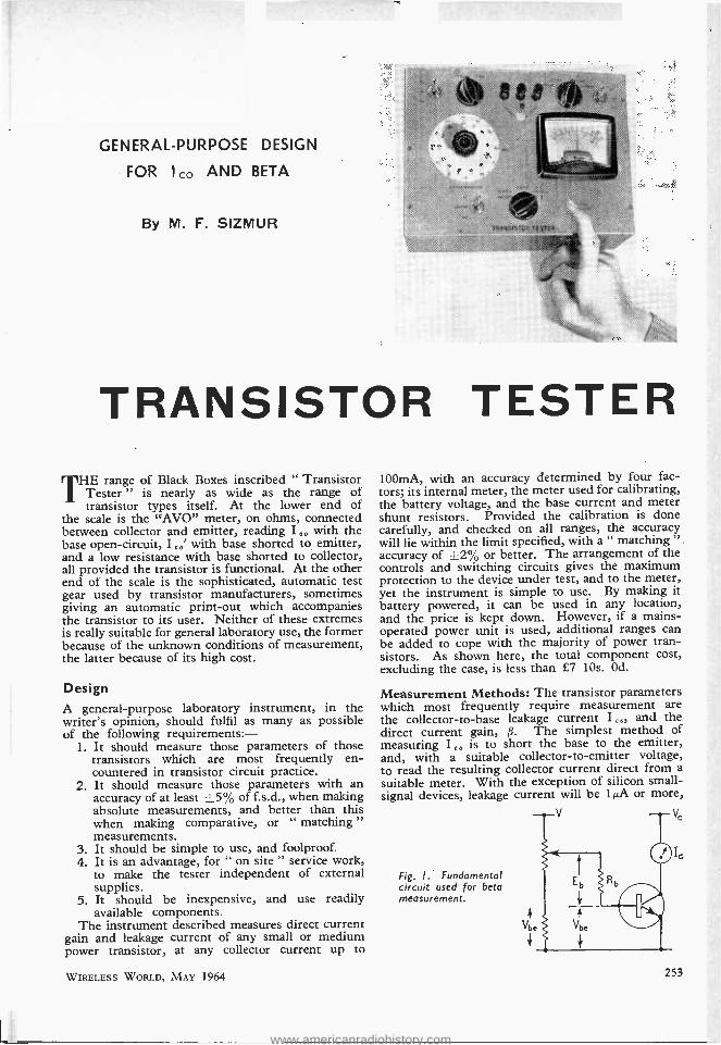
GENERAL- PURPOSE DESIGN
FOR I co AND BETA
By M. F. SIZMUR
TRANSISTOR TESTER E range of Black Boxes inscribed " Transistor
Tester " is nearly as wide as the range of transistor types itself. At the lower end of
the scale is the "AVO" meter, on ohms, connected between collector and emitter, reading I,. with the base open -circuit, I co' with base shorted to emitter, and a low resistance with base shorted to collector, all provided the transistor is functional. At the other end of the scale is the sophisticated, automatic test gear used by transistor manufacturers, sometimes giving an automatic print -out which accompanies the transistor to its user. Neither of these extremes is really suitable for general laboratory use, the former because of the unknown conditions of measurement, the latter because of its high cost.
Design
A general -purpose laboratory instrument, in the writer's opinion, should fulfil as many as possible of the following requirements:
1. It should measure those parameters of those transistors which are most frequently en- countered in transistor circuit practice.
2. It should measure those parameters with an accuracy of at least 15% of f.s.d., when making absolute measurements, and better than this when making comparative, or " matching " measurements.
3. It should be simple to use, and foolproof. 4. It is an advantage, for " on site " service work,
to make the tester independent of external supplies.
5. It should be inexpensive, and use readily available components.
The instrument described measures direct current gain and leakage current of any small or medium power transistor, at any collector current up to
WIRELESS WORLD, MAY 1964
100mA, with an accuracy determined by four fac- tors; its internal meter, the meter used for calibrating, the battery voltage, and the base current and meter shunt resistors. Provided the calibration is done carefully, and checked on all ranges, the accuracy will lie within the limit specified, with a " matching " accuracy of +2% or better. The arrangement of the controls and switching circuits gives the maximum protection to the device under test, and to the meter, yet the instrument is simple to use. By making it battery powered, it can be used in any location, and the price is kept down. However, if a mains - operated power unit is used, additional ranges can be added to cope with the majority of power tran- sistors. As shown here, the total component cost, excluding the case, is less than £7 10s. Od.
Measurement Methods: The transistor parameters which most frequently require measurement are the collector -to -base leakage current I and the direct current gain, ß. The simplest method of measuring I o° is to short the base to the emitter, and, with a suitable collector -to- emitter voltage, to read the resulting collector current direct from a suitable meter. With the exception of silicon small - signal devices, leakage current will be 1 µA or more,
Fig. I. Fundamental circuit used for beta measurement.
V Vc
e
253
www.americanradiohistory.com

and may be measured on a meter with f.s.d. of 100µA. The leakage of small- signal silicon transistors is usually ignored at room temperature, so the inability of the instrument to indicate is not a serious draw- back, while a faulty transistor with high leakage current would give an indication of its condition.
The most common method of measuring ß is to inject a known base current, Ib, into the device under test, and to measure the corresponding collector current on a meter with f.s.d. of, say, 100Ib. The value of ß is then equal to the collector current, and is read direct from the meter scale. Because of its simplicity, this method is widely used, but it has a serious drawback. Most transistor characteristics are functions of collector current, and it is therefore normal circuit practice to operate the transistor with a defined collector current. Consequently, if the tests on the transistor are to be useful, they must be done at the same collector current as will be used in the circuit. This is impossible to achieve with the simple method described above, unless the operating current happens to be ß times the test set base current. It is necessary, therefore, to have a facility for varying the collector current, and hence the base current.
Variations of ß with collector voltage are small, except in the saturation region, so there is little point in making collector voltage variable over a wide range. A detailed investigation of saturation characteristics is best performed either on a proper transistor analyser or in a specially constructed circuit. However, it is possible to obtain a measure- ment of saturated current gain, as described later.
The basic circuit used for measuring ß is shown in Fig. 1.
We define ß = ° Ib Eb
Ib = Rb
- 10 Rb
Eb If Ib is very small compared with the total current
in RVl, then Eb = 0V,
where O is the percentage of potentiometer slider rotation from the lower end, and
ß = Ie Vbe If (a) I is read on a meter scaled 0 -10,
(b) Rb is made equal to IelOa¢
(I a ,,,m is f.s.d.), (c) the potentiometer is scaled with a hyper-
bolic scale from 10 down to 1, then:
ß =I,.B = product of meter reading and dial reading.
This principle is used in at least one commercial test set, but it has two disadvantages.
If the condition I, = RV is to be satisfied, the
i potentiometer is required to dissipate appreciable power when measuring on the highest collector current range. This increases the size and cost of the potentiometer, and in the case of a battery supply, means that large, and consequently expensive,
254
R1 R. Rs Rio R11 R12 R1a R15 R10 R17 R18 R20 R21
Rs
R3 R4 R5 Rs R7 R9
COMPONENT LIST 3.3kf2 394 10052 3352 1.5k52 10012 lOS2 4752 15051 A.O.T. 2kS2 A.O.T. 10052 A.O.T. 33052 A.O.T. 18052 A.O.T.
10052
82052 8.2kí1 ß2k52 820k51 8.2Mí1 100kí
All 1 watt
high stability
(Adjust on Test)
5% 1 watt high stability
All } watt 1% high stability
R14 1(1 5% wire -wound R19 6.8n A.O.T.
N.b., if preferred, 1% tolerance resistors may be selected from R10 -R14, leaving R,6 as the only A.O.T. component.
Values are as follows: Rio R,1 R12 R1s R14
Sw. 1 2P. 2W. Toggle Sw. 2 4P. 4W. Wafer Sw. 3 6P. 5W. Wafer Sw. 4 1P. 2W. Toggle Sw. 5 4P. 2W. Wafer Sw. 6 2P. 2W. Biased toggle Sw. 7 1P. 2W. Toggle
A d.p.s.t. push button would be ideal for Sw.6, but these do not seem to be available.
M.1. 2i in 100µA f.s.d.
29.652 170052 94.5D 8.5851 0.8552
Taylor Instruments Model 40 or Model 32.
Batteries: either 1 -Ever Ready PP11 or 2 -Ever Ready " Bell Battery " No. 126.
batteries must be used. If this is not done, the combined load of collector and potentiometer cur- rents will reduce the battery voltage, and the measure- ment will be in error. Also, since gain is propor- tional to the reciprocal of potentiometer rotation, the dial must be calibrated with an inverse -law scale. Such a scale is very cramped at one end, and this reduces the accuracy of readings.
If the potentiometer slider is shunted to earth by a resistor of value R01, then the slider voltage/
rotation relationship is approximately an inverse law; by choosing RV1 and Rb in this ratio, the power dissipated in RV, for a given base current is con- siderably reduced. The method of measuring ß is the same as before, but the potentiometer dial now has an almost linear scale. The only disad- vantage is that each instrument must be calibrated separately, unless RV, can be obtained with a close tolerance on both total winding resistance and linearity. However, since calibration is necessary for differences in Vb, of silicon and germanium
WIRELESS WORLD, MAY 1964
www.americanradiohistory.com
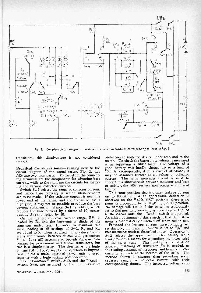
R8 100
PRESS TO READ
Swód Sw5,
Sw la
x10 xl o
R9 100 k
Sw3d R20 330 0
S F
"r0 9V
, .45V
Y a.5'. 1
J.
Io 0-IOOmA
0-IOmA -+ o-ImA
o- ¡opt, Sw2a
Ri5 47
Sw2b - o
RI R2 3.3k 39
FUNCTION ß
jb
Swlb
Ice, O-0ImArD
Ico 0 3mA
C -E s/c
BATTERY
lc m
Sw4 x0.3 x 1
o
Fig. 2. Complete circuit diagram.
r'r Swób Sw5d
Switches are shown in positions corresponding to those in Fig. 3.
transistors, this disadvantage is not considered serious.
Practical Considerations: -Turning now to the circuit diagram of the actual tester, Fig. 2, this falls into two main parts. To the left of the connect- ing terminals are the components for adjusting base current, while to the right are the circuits for meter- ing the various collector currents.
Switch Sw2 selects the range of collector current, and hence base current, at which measurements are to be made. If the collector current is near the lower end of the range, and the transistor has a high gain, it may not be possible to reduce the base current sufficiently. Hence Swl is added, which reduces the base current by a factor of 10; conse- quently ß is multiplied by 10.
On the highest collector current range, RVl is loaded by R, and the base -emitter diode of the transistor under test. In order to maintain this same loading at all settings of Sw2, R2 and R15 are added to R, when required. The values chosen are a compromise between silicon and germanium V b,'s. It is still necessary to provide separate cali- bration for germanium and silicon transistors, but this is a simple matter. The alternative is a high - voltage (50 to 100V) supply for V, which is imprac- tical unless a mains- operated power unit is used, together with a high -wattage potentiometer.
The " Function " switch, Sw3, and the " Read " switch, Sw6, are arranged to give the maximum
WIRELESS WORLD, MAY 1964
protection to both the device under test, and to the meter. To check the battery, its voltage is measured when supplying a 100 ià load. The voltage of a good battery will hardly change up to a load of 100mA; consequently, if it is correct at 90mA, it may be assumed correct at all values of collector current. The same metering circuit is used to check for a short -circuit between collector and base or emitter, the 100 Si resistor now acting as a current limiter.
This same position also indicates leakage current up to 90mA, and if an appreciable deflection is observed on the " C -E S /C" position, there is no point in proceeding to the high Ic (3mA) position. No damage will result if the switch is temporarily set to this position, however, as no voltage is applied to the circuit until the " Read " switch is operated. An added advantage of this switch is that the instru- ment is automatically switched off when not in use.
Provided the leakage current measurements are satisfactory, the Function switch is set to "ß," and measurements made as describedunder " Operation ". Sw2 selects the appropriate meter shunt, while Sw4 provides a means for expanding the lower third of the meter scale. This facility is useful when accurate matching of transistor ß's is needed, as the reading accuracy of the meter, and hence collector current, is lowest at the bottom of the scale. The method shown is cheaper than providing seven separate ranges for collector current, with their corresponding shunts. The increased voltage drop
255
www.americanradiohistory.com

across the meter is of little import, its effect on ß and L. is negligible.
The choice of meter is very wide, the main requirements are a linear moving -coil move- ment, of 100µA f.s.d., with a clear, legible scale, calibrated 0 -10, 0 -3. The one quoted in the parts list seems to be one of the cheapest commer- cial instruments, but it is a simple matter to adapt a government surplus move- ment. Unless there is a drastic reduction in the price of shunts, the method shown, using high stability resistors, is the most economical. The Taylor meter has a coil resist- ance of 700n+20 %, and R16 is selected to provide a total resistance of 850 S2. The high stability resistors are then selected to provide the rele- vant shunt values.
The value of collector volt- age was dictated by availability of batteries, together with a study of conditions at which manufacturers measure P. The latter showed a preference for the range 4.5 to 9 volts, so these two convenient values were chosen. They enable just about every transistor on the market to be tested, with the exception of the 00704. For this transistor, ß is best measured by using 4k volts and a suitable dropping resistor to give V = 3 volts. I e, is 0.112A, so cannot be measured anyway.
A suitable layout for the controls is shown in Fig. 3. A panel area of about 10 x Tin is suitable, with a depth of about 4in to take the batteries. No other dimensions are given, as these depend upon the particular components used. Fig. 4 shows a suitable meter scale.
POLARITY n -p -n p n -p
ß. Ico 0 -100µQ
Ico 0 -3mA -411.0 C -E sic
BATTERY FUNCTION
= DI A X METER
xl v x 1 PRESS TO
READ
0-ImA C-IOmA o-ioopA. .0-100mA
6X03
O
Fig. 3. Suggested front -panal layout. This differs slightly from that shown in the heading photograph.
5 6 7
BATT.
2 D Fig. 4. Meter scale. 0o sfco The scale for the potentiometer is calibrated in the
following manner. Connect a medium power germanium transistor, e.g. 0072, to the terminals, with a low- resistance multirange meter in series with the base. With 9 volts applied to the circuit, and the 0 -100mA range on the I , switch, the potentiometer will vary the base current from just under ImA to just over 10mA. The scale is then calibrated against current:-
Ib(mA) Scale 10 1
5 2 3.3 3 2.5 4 2.0 5 1.67 6 1.43 7 1.25 8 1.11 9 1.0 10
The procedure is then repeated for a suitable silicon transistor, e.g. the 0C206.
256
Operating Instructions
In addition to testing transistors, the tester may be used to check continuity and leakage current of diodes.
Diode Continuity: -The switches are set: V e, 9 volts. Polarity, n -p -n. Function, Battery. The diode is connected, anode to terminal C, cathode to terminal E. On pressing the " Read " button, the battery voltage is indicated on the 0 -10 range of the meter, and should be 9 volts. The " Function " switch is then turned to " C -E S /C," and pressing the " Read " switch will give a meter reading of 7h to 9 volts, depending on the voltage developed across the conducting diode. No deflection of the meter indicates an open -circuit. (N.b., the forward current during this test is about 90mÁ; make sure this is within the device rating.)
Diode Reverse Leakage Current:- Switches set: V 9 volts. Polarity, p -n -p. Function, C -E S /C. A short- circuit in the device will be indicated by a meter reading of 9, or short- circuit, while leakage currents up to 90mA give proportional readings. Provided the leakage current is less than 3mA, the " Function " switch can select the I e, 0 -3mA range, and if less than 100µA, the I 0 -100µA range.
Transistor Short-Circuit:-The transistor is connected to the appropriate terminals, and the Polarity, V , and I , switches set as required. The " Function " switch is first turned to " Battery " which is checked as above, then to " C -E S /C." A short between collector and base or emitter is indicated by a deflection of the meter to 9, or short - circuit, which corresponds to 90mA regardless of the range of the I , switch. Leakage currents up to 90mA will give proportional deflections. Provided the leak- age current is less than 3mA, the " Function " switch can be moved to the next position, and to the I,.0 -100µA position if safe to do so. If I eo should be
WIRELESS WORLD, MAY 1964
www.americanradiohistory.com

required, it can be read on a suitable range, with the base lead disconnected.
Transistor Gain, ß: -In order to prevent damage, the above procedure should always be followed, even if the only information required is the value of ß. Assuming that there are no short -circuits or high leakage currents, the " Function " switch is turned to " ß," and the potentiometer and the x 1/ x 10 switch adjusted until the required collector current is indicated on the meter. The value of ß is then given by:
Dial reading x Meter reading x 1 or x 10. If on a ; < 0.3 range of collector current, then the meter reading is on the 0 -3 scale. In order to avoid over- loading the meter, it is advisable to begin with the dial and x 1/ x 10 switch both set to 10. Such an overload is unlikely to damage the meter, however,
as it is of short duration; the " Read " switch would be released immediately the meter needle went over the scale.
(N.b., it is always necessary to press the " Read " switch to obtain a reading of any sort, as no power is applied to the tester until this switch is closed.)
Transistor Saturated Gain: A suitable resistor R is selected such that 4.5 /Rs gives the collector current required, and connected between the " C " terminal and the collector. The gain is then measured as above.
If desired, the meter can be used as a multirange milliameter, by setting the " Function " switch to " ß," connecting one lead to the " C " terminal, and the other to the pole of Sw6,. With the " Pol- arity " switch at n -p -n, the " C " terminal is positive, and the f.s.d. current is selected by Sw2 and Sw4
A CROSSWORD FOR NUMERATES By A. J. KEY
If you, like me, are baffled by most crosswords, even when given the solution, try this one -it might help to restore your ego. Then give it to some of your literate friends -it might stop them trying to liberalize you.
Clues Across I. R + jX. (1). 3. Couldn't be simpler, at least chemically. (7). 7. Mr eat for the short -wave boys. (3).
9. J x
dx (4).
10. Could be a ratio or a grid. (7). 11. Perhaps the Yanks eat electrons off this. (5). 12. The Met. Men would describe this as " precipi-
tation." (4). 13. If the bias isn't right. distortion may be this. (61. ©© ill 11111 MI= s
FA 111. ::.: : Mal
E 11 11111 11
1111 11. ® lil iiii ®. M. ®
WIRELESS WORLD, MAY 1964
15. It may be focused by a lens but it isn't light. (7, 3).
16. 2 (3).
19 Joule -sec ? (3).
coulomb2 20. You may find these waves in a helix. (10). 25. You might call him the " Father of Geometry."
(6). 27. +ANE =(C3 HS). (4). 29. A place for propounding your pet theory. (5).
30. To make strong but not brittle. (7). 31. Millikan's electrons could be described as this. (4). 32. An electrical sandwich. (3). 33. A doubtful line -up in Soho? (1, 1, 5).
34. fidt. (1).
Clues down 1. The third dimension. (1). 2. Raise the base to this and you're back where
you started. (9). 3. Judge not an instrument by this. (8). 4. No longer ignorant. (7). 5. Effect of HF on glass. 6. Diode in a hole or under a hump ? (6). 7. 186.5 watts per leg apparently. (5). 8. Perhaps this one lived on the Operator Dee. (6)'
11. Of the mind. (6). 14. V,,, -iR1. (2). 16. Nevile Shute took this as the title of his Autobio-
graphy. (5, 4). 17. Brown -black- green. (6). 18. Aptly describes the operation of a monostable
multivibrator. (4 -4). 21. 30,000 c/s to 30,000 Mc ¡s. (2). 22. Ten divisions against nine. (7). 23. Must have been a forceful character in m.k.s.
units. (6). 24. Not the ultimate in sound reproduction. (4 -2).
26. A simple process converting cream to butter. (5).
28. One thing a circle hasn't got. (4). 34. CV. (1)
257
www.americanradiohistory.com

Graphical Aids to Noise Figure
Measurement
THE usual method of measuring noise figures at intermediate and radio frequencies is to measure them over a narrow band of fre-
quencies. The measurement is made by comparison with a noise source such as a temperature -limited diode. The method is fully described by Valley and Wallmanl, who also give details of a suitable circuit for the diode noise source and its power supply. Briefly the method is as follows: - Theory:-A noisy amplifier is represented as a perfect, noise -free amplifier with an equivalent noise generator connected to its input. If there were no equivalent noise generator, the only noise at the output of the amplifier would be the unavoidable Johnson noise due to thermal agitation of the electrons in the source resistance to which the amplifier is connected. The noise figure, usually expressed in dB, is the ratio of the noise power of the equivalent noise generator to the unavoidable noise power from the actual source resistance. In the experimental set -up, shown in block- diagram form in Fig. 1, we measure first the noise out of the amplifier and second the amount of noise that we must put into the amplifier to double its noise output.
Under these conditions the calculable noise from the diode is equal in power to the amplifier's own noise and can be compared with the noise from the source resistance to give the noise figure. The noise power from the diode can be calculated from its (d.c.) anode current and the load resistance with which the diode is terminated. The diode anode current can be varied by varying the filament current and hence its temperature. With reference to
AMPLIFIER UNDER TEST
i
3dó ATTENUATOR
POST
AMPLIFIER
By M. D. WOOD, M.A. (Oxon)*
3dB attenuator as in Fig. 1. The procedure is to obtain an output indication from the amplifier's own noise, insert 3dB (i.e. halve the power into the meter) and then bring up the power from the noise source until the original reading is obtained. Equa- tion 1 then gives the noise figure.
Design procedure: -When one is designing an i.f. or r.f. amplifier the input circuit has to be opti- mized for low noise. Theory is of some use in this respects, as also are the manufacturer's transistor data. Unfortunately, in spite of all the claims made for it, the theoretical approach is little more than an initial guide to sorting out the most likely transistors and the best operating conditions for low noise- and then only if sufficient parameter data are available and one is prepared to manipulate cumbersome expressions. On the other hand, the manufacturer's data are never full enough for all design problems. The trouble is that the four possible variables - noise figure, source resistance, emitter current and frequency are compressed into two or even one graph, with consequent loss of information. A fifth variable, V0$, can be neglected at low voltages - noise figure only increases with Vo$ above five to ten volts.
Having decided as a result of theory and /or data on one or more suitable transistors, and having designed this into an input circuit which is approxi- mately optimum for low noise, two problems have to be solved. First, the circuit must be optimized, and secondly the spread in results with different transistors of the same type must be found. This requires many measurements, and an equal number of calculations based on equation 1. The tedium
Fig. 2 the noise figure is given (see reference 1) by N.F. = 101ogio
Ro R .. .. (1)
Where I is the measured anode current in amps. required to double the amplifier noise output, Ro is the (coaxial) output resistance of the noise source and R is resistance in series.
The noise figure obtained is the so called " full - band noise figure," i.e. the integrated effect over the frequency response of the amplifier under test.
In practice the output meter is not used to measure the actual output power: a simpler method that avoids any non -linearity in the meter is to use the
Ferranti Ltd.
258
CVI7z
Fig. 1. Experimental set -up for measuring noise figure.
R OUTPUT TO
AMPLIFIER UNDER TEST
0
Fig. 2. Noise diode and associated circuit.
WIRELESS WORLD, MAY 1964
www.americanradiohistory.com
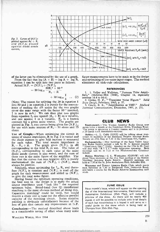
Fig. 3. Curves of (N.F.) I
plotted against Ro -- R,
and (N.F.)2 plotted against diode anode current.
7
5
5
4
3
2
1
dB O
-1 2
3
4
-5 6
:,......, iÍ (mA SCALE ' 11111111
2
100
10 12 -1
14 16
600 700 800 7 \CM\N
(NF)1 -IOLOG10
L80RoxI0t L Ro+R
(N.F)Z =101.00,0[ 1(T,} 4
NOISE DIODE ANODE CURRENT (mA) 18 20 I I I
900 1000
SOURCE RESISTANCE Ro +R (OHMS)
H!! Ell
(OHMS SCALE)
OHMS SCALE)
I 1 1
(I .F.)1 WITH Ro= 75Q
(N.F.. WITH Ro =5011
of the latter can be eliminated by the use of a graph. From the fact that log (A X B) = log A + log B,
equation 1 can be split into two parts as follows: Actual N.F. = (N.F.)t+ (N.F.)2
10 log,. 80R.02 x 10-3
Ro+R + 10 log,. 4 .. (2)
(Note: The reason for splitting the 20 in equation 1
into 80 and + in equation 2 is purely for the conven- ience of making the dB scales for the two graphs cover the same range with the factor 10 -3 inserted, I is now in mA.) We can thus plot two graphs from equation 2, one against (R0 + R) as a variable, and one against I as a variable. R. is a known constant for a given noise source. The graphs are plotted in Fig. 3, two curves being given for (N.F.)1, for use with noise sources of R0= 50 ohms and 75 ohms. Use of Graph:-When optimizing the circuit in terms of source impedance, R in Fig. 2 is varied and the diode current to give 3dB increase is measured for each value. The total source impedance is Ra = R. + R. The graph gives (N.F.)1 in dB corresponding to the total R, in use. The value of (N.F.)2 corresponding to each value of the noise diode anode current is also noted, and the sum of these two is the noise figure of the amplifier. The fact that the curves run into negative dB's is purely mathematical: the sum of (N.F.)1 + (N.F.)2 must always be positive.
Similarly, when optimizing for I$, Ra and there- fore (N.F.)1 is constant and (N.F.)2 is read off the graph for each measurement and added to (N.F.)1 to give the total noise figure.
Having found the optimum operating conditions, the final step in the design is to make the actual source impedance used " look like " the required optimum value. Broad -band (low Q) transformer matching is the most obvious method of doing this. Capacitive matching3 could be used, but would require a shunt coil to tune out the effective parallel capacity of the matching circuit. Series resistive padding is obviously unsatisfactory because of the loss of gain that cancels any improvement in N.F.
Conclusion: -The method described above leads to a considerable saving of effort when many noise
WIRELESS WORLD, MAY 1964
figure measurements have to be made as in the design and optimizing of low -noise input stages. The method eliminates all slide -rule calculations.
REFERENCES 1. 1. Valley and Waltman, " Vacuum Tube Ampli-
fiers," (McGraw -Hill (1948), Chapter 14, especially sections 14.4 to 14.6).
2. Cooke, H. F., " Transistor Noise Figure." Solid State Design, February, 1963, p. 37.
3. Cowie, B. S., " Amplification at VHF." Mullard Technical Communications, December, 1961, p. 151.
CLUB NEWS Bournemouth. -The Wessex Amateur Radio Group now
meets twice a month at the Cricketers Arms, Windham Road. The group is operating a 2 -metre station and is to purchase a 20 -metre s.s.b. transmitter- receiver.
Halifax. -L. L. Cobb (G3UI) will be talking about tran- sistors to members of the Northern Heights Amateur Radio Society on 27th May at 7.30 at the Sportsman Inn, Ogden.
Heckmondwike. -May meetings of the Spen Valley Ama- teur Radio Society include a talk by M. A. Browne entitled " Missilemen 1964 " (14th). Another on the 27th by D. Pratt will deal with " R T T Y " -radio teleprinter operation. Both meetings will be at 7.15 at the Heckmondwike Grammar School.
Melton Mowbray. -J. L. Warrington (G2FNW) will talk about 70cm operation at the 21st May meeting of the Melton Mowbray Amateur Radio Society. Monthly meetings are held at 7.30 at the St. John Ambulance Hall, Asfordby Hill.
Worcester and District Amateur Radio Club, which meets each Saturday at 7.30 in Perdiswell Park, Droitwich Road, also holds a course for the Radio Amateur Examination each week.
JUNE ISSUE Next month's issue, which will appear on the opening day of the International Instruments, Electronics and
Automation Exhibition (25th May), will include a
preview of the show. As there will be nearly 400 stands it will be possible to include only brief details of each but nevertheless it is hoped it will serve as a
useful guide to the show which is being held at
Olympia from 25th -30th May.
E
www.americanradiohistory.com
MAY MEETINGS Tickets are required for some meetings: readers are advised, therefore, to
with the secretary of the society concerned
LONDON 1st. R.S.G.B. -" Aerials " by H. V.
Sims at 6.30 at the I.E.E., Savoy Place, W.C.2.
4th. I.E.E. -" The engineering and scientific aspects of the Canadian iono- spheric satellite " by E. D. R. Shearman and Dr. J. W. King at 5.30 at Savoy Place, W.C.2.
4th. I.E.E. Graduates. -Annual General Meeting at 6.30 followed by " Research in telecommunications " by H. Stanesby at the I.E.E. Savoy Place, W.C.2.
6th. I.E.E. -" Image intensifiers " by Prof. R. L. Beurle at 5.30 at Savoy Place, W.C.2.
6th. I.E.R.E. -" Long -term air traffic control systems concepts " by H. Jessell at 6.0 at the London School of Hygiene and Tropical Medicine, Keppel Street, W.C.I.
7th. I.E.R.E. -Papers on " The new 'test cards D and E" at 6.0 at the Lon- don School of Hygiene and Tropical Medicine, Keppel Street, W.C.1.
7th. Institution of Electronics.- " Variable resistance pressure trans- ducers " by J. Dean at 7.0 at the Lon- don School of Hygiene and Tropical Medicine, Keppel Street, W.C.1.
8th. I.E.E. -Colloquium on " Equip- ment for standards laboratories " at 2.30 at Savoy Place, W.C.2.
11th. I.E.E. -Discussion on " Are transistors reliable enough? " at 5.30 at Savoy Place, W.C.2.
12th. I.E.E. -" U.H.F. television receiving aerials " by C. F. Whitbread at 5.30 at Savoy Place, W.C.2.
12th. I.E.E. & I.E.R.E.- Discussion on " The new H.N.C." at 5.30 at Savoy Place, W.C.2.
13th. I.E.E. -" Electricity and nerves " by Prof. A. F. Huxley at 5.30 at Savoy Place, W.C.2.
13th. I.E.R.E. -Symposium on " Modern techniques for recording and processing seismic signals " at 10.30 a.m. at Birkbeck College, Malet Street, W.C.1.
13th. Royal Society of Arts. -" In- ternational space research " by Prof. P. Auger, chairman French Committee on Space Research, at 6.0 at John Adam Street, W.C.2.
14th. Royal Society. -" Inventive technology: the search for better elec- tric machines " by F. C. Williams at 4.30 at Burlington House, W.I.
16th. R.S.G.B. -Tenth international v.h.f. /u.h.f. convention at Kingsley Hotel, Bloomsbury Way, W.C.1.
21st. I.E.R.E. -" The plumbicon tube " by E. F. de Haan and S. L. Tan at 6.0 at the London School of Hygiene and Tropical Medicine, Keppel Street, W.C.1.
25th. I.E.E. -" Results of the Ex- traordinary Administrative Radio Confer- ence, Geneva, October -November 1963 " by Capt. C. F. Booth at 5.30 at Savoy Place, W.C.2.
26th. I.E.R.E. -Tite Fifth Clerk Maxwell Memorial Lecture by Sir W. Gordon Radley at 6.0 at the London School of Hygiene and Tropical Medi- cine, Keppel Street, W.C.1.
27th. I.E.E. -" The development of secondary surveillance radar for air traffic control" by D. G. Terrington at 5.30 at Savoy Place, W.C.2.
" WIRELESS WORLD " PUBLICATIONS Net
Price COLOUR TELEVISION: N.T.S.C. System, Principles and
Practice. P. S. Carnt, B.Sc.(Eng.), A.C.G.I., A.M.I.E.E.,
By Post
and G. B. Townsend, B.Sc., F.Inst.P., M.I.E.E., A.K.C. 851 - 87;3 RADIO AND ELECTRONIC LABORATORY HANDBOOK
M. G. Scroggie, B.Sc., M.I.E.E. 7th Edition .. 55/- 57;3 PRINCIPLES OF TRANSISTOR CIRCUITS
S. W. Amos, B.Sc.(Hons.), A.M.I.E.E., 2nd Edition .. 25/- 26;- FOUNDATIONS OF WIRELESS, 7th Edition. M. G.
Scroggie, B.Sc., M.I.E.E. . 21/- 22/4 RADIO VALVE DATA. Compiled by the Staff of " Wireless
World " 7th Edition .. 7/6 8/4 SECOND THOUGHTS ON RADIO THEORY
M. G. Scroggie, B.Sc., M.I.E.E. 35/- 36/4 WIRELESS SERVICING MANUAL, 10th Edition
25/- 26/- TRANSISTOR INVERTERS AND CONVERTERS
Thomas Roddam .. . . 42/- ESSAYS IN ELECTRONICS
M. G. Scroggie, B.Sc., M.I.E.E. 42/- 43/1
MICROPHONES A. E. Robertson, B.Sc.(Eng.), A.M.I.E.E., 2nd Edition 75/- 76/2
A complete list of books is available on application. Obtainable from all leading booksellers or from:
ILIFFE BOOKS LTD., Dorset House, Stamford Street, London, S.E.1.
260
communicate
BIRMINGHAM 20th. Television Society. -" Tele-
vision in Kenya " by K. Bowen- Bravery at 7.0 at the College of Advanced Tech- nology, Gosta Green.
EASTBOURNE 12th -14th. Institute of Navigation.-
International convention on " The safety and reliability of sea and air transport: a navigational survey " at the Confer- ence Hall. LIVERPOOL
20th. I.E.R.E." Video telephones" by H. A. Mumford at 7.30 at the Walker Art Gallery.
MANCHESTER 12th. I.E.E. -Annual general meet-
ing of the North- Western Centre at 6.15 followed by " Computers in control of processes -the coming revolution in industry " by Dr. D. N. Truscott at the Renold Building, College of Science and Technology.
SHEFFIELD 20th. I.E.E. -Annual general meet-
ing of the Sheffield Sub-Centre at 6.30 followed by " Electronic data process- ing " by C. W. Mortby at the Univer- sity.
STAFFORD 25th. I.E.E. -" Mathematics as an
educational discipline for the profes- sional engineer " by P. L. Taylor at 7.0 at College of Advanced Technology.
STOKE -ON -TRENT 13th. Inst. Phys. & Phys. Soc.-
" Colour standards and their measure- ments " by Prof. W. D. Wright at 6.30 at North Staffordshire College of Tech- nology.
OVERSEAS 4th -6th. U.S. Army Electronics R.
& D. Labs. -Frequency Control Sym- posium in Atlantic City, N.J., U.S.A.
5th -7th. Electronic Industries Assoc. & I.E.E.E.-Electronic Components Con- ference in Washington, D.C., U.S.A.
11th -13th. I.E.E.E. - Aerospace Elec- tronics Conference in Dayton, Ohas U.S.A.
12th -16th. C.O.S.P.A.R Interna tional Space Science Symposium in Florence, Italy (organized by the Inter- national Committee on Space Research).
19th -21st. I.E.E.E. - Microwave Theory & Techniques Symposium at Long Island, N.Y., U.S.A.
THIS MONTH'S EXHIBITIONS LONDON May 5 -15 Earls Court
Mechanical Handling (Mechanical Handling, Dorset House, Stamford Street, S.E.1.)
May 25 -30 Olympia Instruments, Electronics & Automa- tion (I.E.A,) (Industrial Exhibtions, 9 Argyll Street, W.1)
WIRELESS WORLD, MAY 1964
www.americanradiohistory.com
SYMPOSIUM ON
ELECTRONICS IN THE
AUTOMOBILE INDUSTRY
MANY interesting electronic appli- cations to the automobile industry were discussed during the sym- posium of this title held recently at Birmingham University and organ- ized jointly by the Institution of Electrical Engineers (South Mid- land Centre, Electronics Section) and the Institution of Electronic and Radio Engineers (West Midland Section). Ia all, some 11 papers were presented and the day ended with a brains trust session. The terms of reference for the symposium were, in fact, outlined in the first paper, presented by C. G. Giles of the Road Research Laboratories. Papers followed on the use of elec- tronics in the design and produc- tion of motor cars and on electronic systems used in automobiles.
When it is realized that some 45,000 ignition coils are produced weekly by one of the U.K. leading manufacturers and that each coil is subjected to a test then automatic testing facilities must be invaluable. One automatic system described in- volved resonating the coil primary in a circuit that ensures constant voltage oscillations across the coil. The voltage and current were then used as the two inputs to a Hall multiplier. The d.c. level of the Hall voltage appearing at the output terminals is proportional to the in- phase components of its two inputs and is a measure of power dissi- pated in the coil. The multiplier output voltage, being small, is am- plified via a chopper -stabilized am- plifier. The complete test, carried out by the test equipment once every three seconds, consists of the display of the measurement of the power dissipated in the coil, the display of the value of the voltage generated across the coil primary, the operation of "reject" or "accept" relays and a self -check (against a standard coil). Rejected and accepted coils are channelled into their respective re- ceptacles.
It would appear that in the field of production testing more attention is being paid to surface finish. A new instrument employs a diamond stylus which is driven on the surface around a circular path of 0.25cm radius. The voltages produced by surface undulations are amplified, rectified and integrated to produce an average reading on a meter. The circular path eliminates the neces- sity of lining the instrument up with the grain of the surface.
The last two papers were devoted exclusively to traffic control. In the field of noise measurement, difficul- ties are encountered in choosing test sites since the noise field emitted is influenced by reflecting objects and absorbent surfaces.
WIRELESS WORLD, MAY 1964
FOR
ALL
RADIOcf
ELECTRONIC
COMPONENTS
CONSULT
THt CAO'CE
SIGNAL LAMPS
SWITCHES
CROCODILE CLIPS
PLUGS d SOCKETS
LAMPHOLDERS
KNOBS
TERMINALS
TAG- STRIPS
FUSE -HOLDERS
FUSES
TEST -PRODS
RESISTORS
JACK -PLUGS
JACKS
MICRO- SWITCHES
GROUP BOARDS
ESCUTCHEONS
OF Cf1Ilc5
s'ULG IN
STAND NO, G.83 Q INSTRUMENTS
ELECTRONICS AUTOMATION
EXHIBITION
Ì Olympia 25 -30 May
(Il A. F. BULGIN d CO. LTD., BYE PASS ROAD,
BARKING, ESSEX. TELEPHONE: RIPplaway 5588.
8W W -- -119 FOR FURTHER DETAILS.
261
www.americanradiohistory.com

lf FREE GRID
« IIIIIIIIIIIIIIIIIIIIIIIIIIIIIIIIIIIIIIIIIIIIIIIIIIIIIIIIIIIIIIIIIIIIIIIIIIIIIIIIIIIIIIIIIIIIIIIIIIIIn11P."".' lII IIIIIII IIIIIIIIIIIIIIIIIIIIIIIIIIIIIIIIIIIIIIuIUm ,tsIIL
On this page, to which many of our readers have been accustomed to turn first on reading each fresh issue, we print this month a
71 selection from many tributes we have received to "Free Grid" (N. P. 3
Vincer- Minter) whose death we recorded on page 184 of the previous E
issue.
From " Cathode Ray" Though Wireless World readers
might normally find it hard to believe I could be at a loss for words, they will I am sure readily understand the difficulty in expressing my feeling at the news that there will be no more " Unbiased " comments. Although normally placed last in the issue, they were usually the first I read, and per- haps the only feature I never allowed to go unread. " Free Grid's " char- acteristic vein of fantasy was mingled with the devastating common sense of the child who asks questions of the pundits. And many of his early fan- tasies have turned out to be pro- phecies.
With his ecclesiastical background, " Free Grid " would have under- stood my saying that he kept the best wine to the last. His final contribu- tion is one of the wittiest of all. And to me, especially, it has a bitter -sweet flavour being the best example of his personal repartee. I value not only his direct compliment, but also the compliment implied in his criticism, for clearly he expected me to be quantitatively accurate even in what he correctly described as a trivial matter. The figure referred to was quite immaterial to the argument and was only quoted at all to indicate the order of magnitude as a contrast to the unimaginably small fraction of a
second in electronic precession. But I am grateful for this posthumous reminder never to rely on memory.
I am grateful too for his weight of classical authority on the side of my forlorn voice in condemning the practice, confined to electronic Eng- lish, of treating " data " as singular.
Even in his criticisms, " Free Grid " was always good- natured, never unkind, and always ready to admit it if he found himself in the wrong. In these days when unpre- cedented efforts are made to amuse, real wit is still rare. " Free Grid " had it.
From W. Grant I shall miss " Free Grid." He was
a master of the slow and telling " squeg " when pricking pompous balloons, and a prompter of, " Find out yourself."
262
Front E. Aisberg, Director "Toute l'électronique" (formerly "Toute la Radio ")
J'ai l'impression d'avoir ainsi perdu un vieil ami personnel, ami que je retrouvais tous les mois avec plaisir depuis 1930 et qui personni- fiait pour moi cet humour anglais que j'apprécie tant et qui n'a jamais déserté les pages de Wireless World.
From W. J. Baker, Technical Editor, The Marconi Company.
In common, I am sure, with all your readers, I was much dismayed to hear of the death of " Free Grid," whose page has been a constant de- light to me since those far-off days when W.W. was fourpence a copy.
To us he was not just a contribu- tor but an ageless institution. One might just as well think of Salisbury Plain without Stonehenge as W.W. without " Free Grid." Now he has gone and we shall sorely miss his inimitable blend of wit, erudition and balloon -puncturing.
From Robert Briggs -Bury As a subscriber to Wireless
World for 45 years without a break, I should like to pay a sincere tribute to the late Norman Preston Vincer- Minter, who for three -quarters of that period contributed regularly under the familiar nom -de -plume of " Free Grid." I am sure that many other readers of long standing will wish to be associated with this.
Always eminently readable, never straining for effect or a bore, he gave many of us a great deal of pleasure and amusement, often interlaced with pieces of unusual and interest- ing information. I had the pleasure of exchanging several letters with him over the years, and though he chose always to remain firmly behind his veil of anonymity, he was a charming and rewarding correspon- dent. He had an unusual flair in his particular métier, and I for one shall remember him with gratitude and affection.
There are some who maintain that even a morsel of lighthearted badinage is out of place in a digni- fied, technical journal like Wireless World. But the inconsequential soufflé has its rightful place at any repast and, after all, as W. H. Davies asks : " What is this life if, full of care, we have no time to stand and stare? "
Wireless World will not be quite the same without him, and I know that many of us are saddened to realize he will no longer be with us (if I may quote his very last words) to " put his foot in it again."
Front N. G. H. Browning Most of your readers will be
unable to remember a time when they were not entertained by the gentle satire and puckish humour of the late " Free Grid " and it was typical of him to introduce us in his last contribution to such a whim- sical idea as " South Bank Science."
Now that we have been deprived of such an old friend, may I suggest that some of his outstanding para- graphs, illustrated by one or two of the incomparable sketches of yester- year, be published as a tribute to his memory.
From W. H. Jarvis I have been a regular reader of
Wireless World since the old days of its appearance as a weekly at 3d or 4d, if I remember correctly.
During the whole of this time " Free Grid " has been a constant joy. His debunking of all forms of pomposity and his unfailing accuracy have always pleased me. His clever tilts at manufacturers and their ap- parent lack of appreciation of our requirements will be remembered for a long time.
It is sad when we lose our friends. First we lose the contributions of " Diallist." And now irrevocably, " Free Grid." Wireless World can never be the same again. Requiescat in Pace.
WIRELESS WORLD, MAY 1964
www.americanradiohistory.com