· PDF file614 Wireless World Audio Signal Generator-2 617 ... Dorset House, Stamford Street,...
66
Editor: F. L. DEVEREUX , B.sc. Assistant Editor: H.W.BARNARD Editorial: P. R. DARRINGTON D. C. ROLFE D. R. WILLIAMS Drawing Office: H. J. COOKE Production: D.R.BRAY Advertisement lvf.anager: G. BENTON ROWELL VOLUME 69 No. 12 PRICE: 2s 6d. FIFTY- THIRD YEAR OF PUBLICATION Wireless World ELECTRONICS, RADIO, TELEVISION DECEMBER 1963 579 Editorial Comment 580 Transistor Aerial Pre-amplifier 583 Space Communications 584 587 593 PAL Manufacturers' Products New Low-noise Transistor Microphones-2 By M. V. Callendar By M. Cox Circuit for Electrostatic By P. J. Baxandall 598 Three-watt Transistor Audio Amplifier By T. D. Towers 605 \Vorld of Wireless 607 Personalities 609 · News from Industry 611 1963 International Radio Communications Exhibition 614 Wireless World Audio Signal Generator-2 617 Letters to the Editor 619 Fylingdales 621 Electronics for Civil Aviation 624 D.C. Inverter for Electric Shavers 627 H.F. Predictions-December 628 Unbiased 630 December Meetings Managing Director: W. E. Miller, M.A., M.Brit.I.R.E. By J. R. Nowicki By " Free Grid , Iliffe Electrical Publications Ltd., Dorset House, Stamford Street, London, S.E.l Please address to Editor, Advert•sement Manager or Publisher as appropriate ©nitre Electrical Publications Ltd., 1963. PermissiOn in writing from the Editor must first be obtained before letter- press or illustrations are reproduced from this !ournal. Brief abstracts or comments are allowed provided acknowledgement to the journal is given. PUBLISHED MONTHLY (4th Monday of preceding month). 1'elephone: Waterloo 3333 (70' lines). Telegrams: "Ethaworld, London Telex." Cables: "Ethaworld, London, S.E.l." Annual Subscriptions: Home £2 Os. Od . Overseas £2 5s. Od. Canada and U.S.A. $6.50. Second-class mail privileges authorized at New York, N.Y. BHANCH OFFICES: BIRMINGHAM: l{ing Edward House, New St reet, 2. Telephone: Midland 7191. COVEN1'RY: 8- 10, Corporation Street. Telephone: Coventry 25210. GLASGOW: 62, lluclmnan Street, C.l. Telephone: Centrall265-G. MANCHESTER: 260, Deansgatc, 3. 1'e/eplwne: Blackfriars 4412. NEW YOHK OFFICE: U.S.A.: lll, Broadway, G. 'l'elephone: Digby 9-ll97. Wireless World ELECTRONICS, RADIO, TELEVISION DECEMBER 1963 F. L. DEVEREUX, B.sc. Assistant Editor: H. W. BARNARD Editorial: P. R. DARRINGTON D. 0. ROLFE D. R. WILLIAMS Drawing Office: H. J. COOKE Production: D. R. BRAY Advertisement Manager: G. BENTON ROWELL By M. Cox 579 Editorial Comment 580 Transistor Aerial Pre-amplifier By M. V. Callendar 583 Space Communications 584 PAL By M. Cox 587 Manufacturers' Products 593 New Low-noise Transistor Circuit for Electrostatic Microphones—2 By P. J. Baxandall 598 Three-watt Transistor Audio Amplifier By T. D. Towers 605 World of Wireless 607 Personalities 609 News from Industry 611 1963 International Radio Communications Exhibition 614 Wireless World Audio Signal Generator—2 617 Letters to the Editor 619 Fylingdales 621 Electronics for Civil Aviation 624 D.C. Inverter for Electric Shavers By J. R. Nozoicki 627 H.F. Predictions—December 628 Unbiased By " Free Grid " 630 December Meetings By J. R. Nozoicki By " Free Grid " VOLUME 69 No. 12 PRICE: 2s 6d. Managing Director: W. E. Miller, M.A., M.Brit.i.R.E. Iliffe Electrical Publications Ltd., Dorset House, Stamford Street, London, S.E.I FIFTY-THIRD YEAR OF PUBLICATION Please address to Editor, Advert'sement Manager or Publisher as appropriate ©Iliffe Electrical Publications Ltd., 1963. Permission in writing from the Editor must first be obtained before letter- press or illustrations are reproduced from this journal. Brief abstracts or comments are allowed prov.ded acknowledgement to the journal is given. PUBLISHED MONTHLY (4tl) Monday of preceding month). Telephone: Waterloo 3333 (70 lines). Telegrams: " Ethaworld, London Telex " Cables: " Ethaworld, London, S.E.I." Annual Subscriptions: Home £2 0s. Od. Overseas £2 5s. Od Canada and U.S.A. $0.50. Seeond-elass mail privileges authorized at New York, N.Y. BRANCH OFFICES: BHiM1NGHAM; Kjng Edward House, New Street, 2. Telephone: Midland 7191. COVENTRY: 8-10, Corporal,on Street. Telephone: Coventiry 25210 GLASGM 02 Buchanan Street, C.l. Telephone: Central 1205-0. MANCHESTER: 200, Deansgatc, 3. Telephone: Blacktnars 1412. NEW YOUK OFFICE: U.S.A.: Ill, Broadway, 0. Telephone: Oigby 9-1197. www.americanradiohistory.com
Transcript of · PDF file614 Wireless World Audio Signal Generator-2 617 ... Dorset House, Stamford Street,...

Editor:
F. L. DEVEREUX, B.sc.
Assistant Editor:
H.W.BARNARD
Editorial:
P. R. DARRINGTON
D. C. ROLFE
D. R. WILLIAMS
Drawing Office:
H. J. COOKE
Production:
D.R.BRAY
Advertisement lvf.anager:
G. BENTON ROWELL
VOLUME 69 No. 12
PRICE: 2s 6d.
FIFTY-THIRD YEAR
OF PUBLICATION
Wireless World ELECTRONICS, RADIO, TELEVISION
DECEMBER 1963
579 Editorial Comment
580 Transistor Aerial Pre-amplifier
583 Space Communications
584
587
593
PAL
Manufacturers' Products
New Low-noise Transistor Microphones-2
By M. V. Callendar
By M. Cox
Circuit for Electrostatic By P. J. Baxandall
598 Three-watt Transistor Audio Amplifier By T. D. Towers
605 \Vorld of Wireless
607 Personalities
609 · News from Industry
611 1963 International Radio Communications Exhibition
614 Wireless World Audio Signal Generator-2
617 Letters to the Editor
619 Fylingdales
621 Electronics for Civil Aviation
624 D.C. Inverter for Electric Shavers
627 H.F. Predictions-December
628 Unbiased
630 December Meetings
Managing Director: W. E. Miller, M.A., M.Brit.I.R.E.
By J. R. Nowicki
By " Free Grid ,
Iliffe Electrical Publications Ltd., Dorset House, Stamford Street, London, S.E.l
Please address to Editor, Advert•sement Manager or Publisher as appropriate
©nitre Electrical Publications Ltd., 1963. PermissiOn in writing from the Editor must first be obtained before letter
press or illustrations are reproduced from this !ournal. Brief abstracts or comments are allowed provided acknowledgement
to the journal is given.
PUBLISHED MONTHLY (4th Monday of preceding month). 1'elephone: Waterloo 3333 (70 ' lines). Telegrams: "Ethaworld,
London Telex." Cables: "Ethaworld, London, S.E.l." Annual Subscriptions: Home £2 Os. Od . Overseas £2 5s. Od. Canada and U.S.A.
$6.50. Second-class mail privileges authorized at New York, N.Y. BHANCH OFFICES: BIRMINGHAM: l{ing Edward House,
New Street, 2. Telephone: Midland 7191. COVEN1'RY: 8-10, Corporation Street. Telephone: Coventry 25210. GLASGOW: 62,
lluclmnan Street, C.l. Telephone: Centrall265-G. MANCHESTER: 260, Deansgatc, 3. 1'e/eplwne: Blackfriars 4412. NEW YOHK
OFFICE: U.S.A.: lll, Broadway, G. 'l'elephone: Digby 9-ll97.
Wireless World
ELECTRONICS, RADIO, TELEVISION
DECEMBER 1963
F. L. DEVEREUX, B.sc.
Assistant Editor:
H. W. BARNARD
Editorial:
P. R. DARRINGTON
D. 0. ROLFE
D. R. WILLIAMS
Drawing Office:
H. J. COOKE
Production:
D. R. BRAY
Advertisement Manager:
G. BENTON ROWELL
By M. Cox
579 Editorial Comment
580 Transistor Aerial Pre-amplifier By M. V. Callendar
583 Space Communications
584 PAL By M. Cox
587 Manufacturers' Products
593 New Low-noise Transistor Circuit for Electrostatic Microphones—2 By P. J. Baxandall
598 Three-watt Transistor Audio Amplifier By T. D. Towers
605 World of Wireless
607 Personalities
609 News from Industry
611 1963 International Radio Communications Exhibition
614 Wireless World Audio Signal Generator—2
617 Letters to the Editor
619 Fylingdales
621 Electronics for Civil Aviation
624 D.C. Inverter for Electric Shavers By J. R. Nozoicki
627 H.F. Predictions—December
628 Unbiased By " Free Grid "
630 December Meetings
By J. R. Nozoicki
By " Free Grid "
VOLUME 69 No. 12
PRICE: 2s 6d.
Managing Director: W. E. Miller, M.A., M.Brit.i.R.E.
Iliffe Electrical Publications Ltd., Dorset House, Stamford Street, London, S.E.I
FIFTY-THIRD YEAR
OF PUBLICATION Please address to Editor, Advert'sement Manager or Publisher as appropriate
©Iliffe Electrical Publications Ltd., 1963. Permission in writing from the Editor must first be obtained before letter- press or illustrations are reproduced from this journal. Brief abstracts or comments are allowed prov.ded acknowledgement to the journal is given.
PUBLISHED MONTHLY (4tl) Monday of preceding month). Telephone: Waterloo 3333 (70 lines). Telegrams: " Ethaworld, London Telex " Cables: " Ethaworld, London, S.E.I." Annual Subscriptions: Home £2 0s. Od. Overseas £2 5s. Od Canada and U.S.A. $0.50. Seeond-elass mail privileges authorized at New York, N.Y. BRANCH OFFICES: BHiM1NGHAM; Kjng Edward House, New Street, 2. Telephone: Midland 7191. COVENTRY: 8-10, Corporal,on Street. Telephone: Coventiry 25210 GLASGM 02 Buchanan Street, C.l. Telephone: Central 1205-0. MANCHESTER: 200, Deansgatc, 3. Telephone: Blacktnars 1412. NEW YOUK OFFICE: U.S.A.: Ill, Broadway, 0. Telephone: Oigby 9-1197. www.americanradiohistory.com

72 (ADVERTISEMENT) ~IRELESS ~ORLD DECEMBER, 1963
THE FIRST COMPLETE RANGE OF VALVES FOR DUAL STANDARD TV The task of providing the valves that would be needed for u.h.f . .--------------625-Iine transmissions was one for which Mullard was well prepared. The extensive research and manufacturing resources of the company enabled the various complexities of the new system to be studied long in advance, solutions to be reached, and production facilities organised to :t;neet the needs of the set manufacturers.
The new programme will use the 625-line · standard with negative vision modulation instead of the 405-line standard and positive modulation of the present services. Also it will use frequencymodulated sound instead of amplitude-modulated sound, and will be transmitted at ultra high frequencies instead of very high frequencies. It is in respect of these differences that Mullard has introduced specially designed valves which, with other wellestablished Mullard types, comprise the first complete range of valves for switchable television receivers.
WHAT'S NEW IN Line Timebase ValvesTHE NEW SETS PCF802, PL500 and PY88
These articles describe the latest Mullard developments for entertainment equipment
Valves for tuners and I.F. stagesPC86, PC88 and PCF801 The need for valves to operate at the ultra high frequencies is met in many of the new receivers by the two Mullard u.h.f. tuner triodes, the PC86 and PC88. The latter operates as an r .f. amplifier and the former as a selfoscillating mixer. Both valves use frame grids and consequently possess a high value of mutual conductance. In both, grid-lead inductance and internal capacitances are reduced to a minimum. The performance and versatility of the Mullard PCF801 make it an ideal choice for television receivers designed for both v.h.f. and u.h.f. reception. It can function as an oscillator-mixer in v.h.f. tuners and as a controlled i.f. amplifier following a u.h.f. tuner. Two frame-grids are incorpora ted in the valve: the triode grid and the pentode control grid, which has also been designed with a variable-mu characteristic. Outstanding properties of the PCF801 are small interelectrode capacitances, a high conversion conductance and a remote cut-off characteristic.
I
With the adoption of negative vision modulation for the new television service, receivers have been produced using line oscillators operating on the flywheel principle, and theM ullardPCF802 has been developed specifically
__ . ..J
FM SOUND for this application. In a · typical mode of operation DEMODULATION thepentodesectionofthePCF802 • h EHgO will be used as a sine-wave oscil- USing t e lator whose frequency is control-led by the triode section of the An economical circuit incorporvalve functioning as a reactance ating the Mullard EH90 heptode valve. Special attention has been has been devised for the detecpaid in the development of the tion of the f.m. sound transmisnew valve to minimising hum sions of the 625-line television and microphonia interference, system, and this circuit-the which can be troublesome in this locked-oscillator discriminator type of line-oscillator circuit. -is already appearing in some Furthermore, the amplification of the latest dual-standard refactor of the triode section of the ceivers. This type of circuit devalve is high, thus making the mands good electron coupling section particularly suitable for between the first and third grids operation as a reactance valve. ofthevalveandagoodfrequency-In many new dual-standard re- ~o-~mplitude transfer cha:racterceivers, the task of ensuring IStiC, and these are prov:Ided by comparable performance between the ~H90. The valve will thus the two line standards, despite contnbut.e notably to the benethe higher energy requirements fits acc~m~g from the f.m. sound of the 625-line system, has been transmiSSIOns of BBC-2. simpli!led by utilising the Mul- also more stringent with 625-line lard hne ~:mtput pen to de, type operation. The Mullard PY88 has ~L500. Thi~ valve J:as an excep- a heater-to-cathode voltage rattwnally high ratio. of anode ingof6·6kVandpeakandaverage cur~ent to scree~-grid current current ratings of 550 and 220mA achieved by antnt~rely ~ewform respectively. With these ratings, of a~ode-the cavitr~p ~node- the PY88 is well equipped to meet and ~s cap~ble of delivering the the requirements of 625-line opr~qmred high values of defiec- eration, and the valve is particutwn power· larly suitable for stabilised timeBooster diode requirements are base circuits using the PL500.
MVE 15)96
3WW- 110 FOR FURTHER DETAILS.
72 (Advertisement) Wireless World December 1963
THE FIRST COMPLETE RANGE OF
VALVES FOR DUAL STANDARD TV
The task of providing the valves that would be needed for u.h.f. 625-line transmissions was one for which Mullard was well pre- pared. The extensive research and manufacturing resources of the company enabled the various complexities of the new system to be studied long in advance, solutions to be reached, and production facilities organised to meet the needs of the set manufacturers.
The new prog-amme will use the 625-hne standard with negative vis: »n lodulation instead of t; e 405-line standard a-id y osil ve modulat in of the present services Also it will use 1 eor^ ;y- nodulated omu insteai of a iplitude-modulated sound and will be transrr tted at ultra high frequencies instead of very high fi - qr 'ncies. It is i . 3sp ct of th se differences that Mullard has in,, iduced special - designed valves which, with other we established Mullard ty es, l emprise the first complete range f valves for switchable television receivers.
I
WHAT'S NEW IN
THE NEW SETS hese articles describe the
latest Mullard developments for entertainment equipment
PC86, PG88 and PGF801
The need for valves to operate at the ultra h i frequencies is met
1 many of the new receivers by the jwo Mullard u.h.f. tun r triodes, the PC86 and PC88. The latter perateg as an r.f. ampli- fiei and the former as a self- oscillating mixer. Both valves use frame ids and consequently possess a high value of mutual conductance. In both, grid-lead inductance and internal capacit- ances are reduced to a minimum.
The perfo: imncc nd versatility of the Mullard PCF801 make it an ideal choice for television re- ceivers designed for both v.h.f. and u.h.f. recept. in. It can func- tion as an oscillator-mixer in v. .f. tuners and as a controlled i.f. ampliflei following a u.h.f, tuner. Two frame-grids are in- corporated in the valve: the 3riode grid and the pentode con- tro grid, which has also been designed with a variable-mu characteris 1c. O itstanding pro- perties of the PCF801 are small interelectrode capacitances, a high conversion conductance and a remote cut-off characteristic.
Line Timebase Valves-
PCF802, PL500 and PY88
With the ciop-ion of negative is m modulation for tl 3 new
television service, receivers have been produced using line oscilla- tors operating on le flywheel principle, and the Mullard PCF802 has been developed specifically for this application.
] o a typical mode of operation the pentode section of the PCF802 will be sed as a sine-wave oscil- lator whose frequency is control- led by the riode section of the v£ ve functlc ling as a reactance vs ve.Si cia attention has been : paid n the development of the new va ve to minimising hum 1 a id nicr" phonic interference, 1 which can »e troublesome in this ^ type of line-oi llatoi circuit. ■ Furthermore, the amplification < factor of Li triode section of the < valve is hi; 1, thus making the section particularly suitable for operat on as a reactance valve.
In many new dual-standard re- ceivers, the task of ensuring c mparable performance between the t m line standards, despite the high* • energy requirements of the 625-line system, has been implifled by utilising the Mul- r
h rd ine output pentode, type c(
PL500. This valve has an excep- r tionaDy high ratio of ano b cun mt to screen-grid current achieved by an entirely new form of anode—the 'cavitrap' anode— and is capable of delivering the required righ values of deflec- tion power. i
FM SOUND
DEMODULATION
using the EH90
An economical circuit incorpor- atinr the dullard EH90 heptode has been devised for the detec- tion of the f.n sound transmis- sions of the 625-line television system, a . this circuit — the lockrd-oscillator discriminator —is already appearing in some of the latest dual-standard re- ceivers. This type of circuit de- mands good electron coupling between the first and third grids of the valve and a good frequency- to-amplitude transfer character- istic, ai 1 these are provided by the EH90. The valve will thus contribute notably to the bene nts accruing frm. the f.m. sound transmissions of BBC-2.
Booster diode requirements are
also more stringent with 625-line operation. The Mullard PY88 has a heater-to-cathode voltage rat- ing of 6 • 6kV and peak and average currer ratings of 550 and 220mA respectively. With these ratings, the PY88 is well equipped to meet the equirements of 625-line op- eration, and the valve is par cu- larly suitable for stabilised time- base circuits using the PL500.
MVE ipdS
3WW—110 FOR FURTHER DETAILS. www.americanradiohistory.com

Civil Science
THE Committee under the chairmanship of Sir Burke Trend, appointed by the Prime Minister in March 1962 to consider whether any changes are desirable in the organization of civil science has now published* an analysis of the problems as a basis for discussion.
The report gives clear definitions of the functions of Research Councils and Departments, of the responsibility of the Minister for Science, and the differences betw€en votes of money and grants-inaid. The complementary functions of D.S.I.R. (under the Minister for Science) and of the National Research and Development Council (N.R.D.C., under the Board of Trade) are well brought out, and the report as a whoie is an invaluable guide through the labyrinth of Government science as it exists today. That this is indeed labyrinthine may be gathered from page 20 of the report dealing with space research in which we are told that although the supervision of the activities of the Ministry of Aviation, the Post Office, the Royal Society and D.S.I.R. rests with the Minister for Science, the costs incurred "lie where they fall".
The Committee concludes "that the various agencies concerned with the promotion of civil science do not in the aggregate constitute a coherent and articulated pattern of organization" and "that the arrangements for co-ordinating the Government's scientific effort and for apportioning the available resources between the agencies on a rational basis are insufficiently clear and precise". These are strong words, and the Committe-e backs them by citing, among other things, the example of the Admiralty's responsibility for the Royal Observatory despite the fact that responsibility for other forms of research in astronomy rests with. D.S.I.R.
The remedies suggested are drastic and would involve among other things a dismantling and complete reconstruction of D.S.I.R. Some of its functions (e.g. hydrological and fisheries research) would be transferred to a new Natural Resources Research Council, while other divisions, physics, chemistry, astronomy, biology and " earth sciences " would be reorganized under a Science Research Council (to be run on similar lines to the Medical and Agricultural Research Councils, which gain the ·Committee's unqualified approval). The remaining function of D.S.I.R. in promoting the application of science to industrial processes would be combined with those of N.R.D.C. and other Government bodies in a new Industrial Research and Development Authority (I.R.D.A.). It is this Authority which, it is suggested, should be responsible for the
*"Committee of Enquiry into the Organisation of Civil Science," Connd. 2171, H.M. Stationery Office. Price 4s.
WIRELESS WORLD, DECEMBER 191'>3
VOL 69 NO 12 DECEMBER 1963
majority of the research stations now managed by the D.S.I.R. among which, though it is nowhere :-,pecificaily mentioned in the report, the Radio Research Station will presumably be included.
We hope that before the Government acts on the recommendations of the Trend Committee we may be told more about electronics and radio resear-:::h, how ·it can be better co-ordinated and where it will fit into the new labyrinth. The Committee acknowledges in Appendix 1 the fact that it has received evidence from "The Institution of Radio Engineers" (presumably Brit.I.R.E.), and elsewhere it is announced that D.S.I.R. and industry have undertaken a further study of research in electronics. So there should be ample material for consideration, and a possible supplementary report.
Our Questionnaire Form-filling is now established as a feature of
modern life. Farmers complain that it leaves them little time to walk their fields. Some, on the other hand, find in it a curious fascination-like doing crossword puzzles; the sight of the empty spaces evokes a compulsive urge to pick up pencil or pen.
To all our readers, whether or not they fit into either of these categories, we commend the questionnaire which will be found near the front of this issue and ask them to help us by marking and returning it now, so that our statistical department can get to worv(":with its analytical mysteries, and the editor can discover what trends have developed in readers' tastes since we last issued a questionnaire in 1960. He will appreciate any time and trouble you can devote to constructional criticism on matters not covered by the questions on the form, but whether or not you feel that these questions are the right ones he still hopes that you will answer them all.
Editors are supposed to know their readers and their wants and are usually confident that they do. But when other hard-visaged and influential people ask them to substantiate their opinions with facts it is sometimes less than satisfactory to point to a large aggregate circulation without being able to outline its structure.
As a result of the analysis made in 1960 we were able to confirm, for instance, that a large proportion (60%) of our readers were professionally engaged in electronics and also that we had the support of a large body of readers of purely amateur status.
All such factors are helpful in confirming present policy or suggesting ways in which the balance of contents of the journal might with advantage be adjusted in the future.
For your co-operation we thank you in advance.
579
VOL 69 NO 12 DECEMBER 1963
Civil Science
THE Committee under the chairmanship of Sir Burke Trend, appointed by the Prime Minister in March 1962 to consider whether any changes are desirable in the organization of civil science has now published* an analysis of the problems as a basis for discussion.
The report gives clear definitions of the functions of Research Councils and Departments, of t' ; re- sponsibility of the M i jter for Science, and the differences between votes of money and grants-in- aid. The complementary functions of D.S.I.R (under the Minister for Science) and of the National Research and Development Council (N.R.D.C., under the Board of Trade) are well brought out, and the report as a whole is an invaluable guide through the labyrinth of Government science as it exists today. That this is indeed labyrinthine may be gathered from page 20 of the report dealing v/ith space research in which we are told that although the supervision of the activities of the Ministry of Aviation, the Post Office, the Royal Society and D.S.I.R. rests with the Minister for Science, the costs incurred "lie where they fal
The Committee concludes " that the various agencies concerned with the promotion of civil science do not in the aggregate constitute a coherent and articulated pattern of organ nation" and "that the arrangements for co-ordinat: ig the Government's scientific effort and for apportioning the available resources between the agencies on a rational basis are insufficiently clear and precise ". These are strong words, and the Committee backs them by citing, among other things, the example of the Admiralty's responsibility foi the Royal Observatory despite the fac ; that responsibility for other forms of research in astronomy rests w h D.S.I R.
The remedies suggested are drastic and would involve among other things a dismantling and com- plete reconstruction of D.S.I.R. Some of its func- tions (e.g. hydrological and fisheries research) would be transferred to a new Natural Resources Research Council, while other divisions, physics, chemistry, astronomy, biology and "earth sciences" would be reorganized under a Science Research Council (to be run on similar lines to the Medical and Agri- cultural Research Councils, which gain the ( om- mittee's unqualified approval). The r:n.. lining function of D.S.I.R. in promoting the application of science to industrial processes would be combined with those of N.R.D.C. and other Government bodies in a new Industrial Research and Develop- ment Authority (I.R.D.A.). It is this i m lor y which, it is suggested, should be responsible for the
*cc Committee of inquiry into the Organisation of Civil Science." Connd. 'A 71. H.M. Stationery Office. Price 4s.
Wireless World, December 19«
majority of the research stations now managed by the D.S.I.R. among which, though it is nowhere spei - ifically mentioned i the report, the Radio Research Station will presumably be included.
We hope that before the Government acts on the recommenda ons of the Trend Commit :e we may be told more about electronics and radio researc , how it can be better co-ordinated and where it will fit into the new labyrinth. The Committee ack- nowledges in Appendix 1 the fact that it has received evidence from The Institution of Radio Engineers " (presumably Brit.I.R.E.), and elsewhere it is an- nounced that D.S.I.R. and industry have undertaken a further study of research in electronics. So there should be ample material for cons' leration, and a possible supplementary report.
Our Questionnaire
Form-filling is now established as a feature of modern life. Farmers complain that it leaves them little time to walk their fields. Some, on the other hand, find in it a curious fascination—like doing crossword puzzles; the sight of the emp j spaces evokes a compulsive urge to pick up pencil or pen.
To all our readers, whether or not they fit into either of these categories, we commend the question- naire which will be found near the front of this issue and ask them to help us by marking and re- turning it now, so that our sta stical department can get to work/with its analytical mysteries, and the editor can discover what trends have developed in readers' tastes since we last issued a questionn ire in 1960. He will appreciate any time and trouble you can devote to constructional cm cism on matters not covered by the questions on the form, but whether or not you feel that these quest. jns are the right ones he still hopes that you will answer them all.
Editors are supposed to know their readers and their wants and are usually confident that icy do. But when other hard-visaged and influential people ask them to substantiate their opinions v^th fa ts it is sometimes less than satisfactory to p int to a large aggregate circulation without being able to outline its structure.
As a result of the analysis made in 1960 we were able to confirm, for instance, that la; ;e proportion (60%) of our readers were profess, onally engagea n electronics and also that we had the support of a large body of readers of purely amateu: status.
I such factors are helpful in confirm ig present policy or suggesting ways in which the balance of contents of the journal might \ ith advantage be adjusted in the future.
For your co-operation we thank you in advance.
579
www.americanradiohistory.com

Transistor Aerial IT i.s unfortunate that, except in areas fairly close to a transmitter, the most obvious difference between the first 625-line transmissions available and the old 405-line TV (on v.h.f.) will often take the form of a worsening of the noise in the picture.
The average field strength at a given (longish) distance from a main transmitter will not usually be greatly different on u.h.f., but there is a Joss of 6 io 9 dB in signal picked up by a good outside aerial, plus a worsening of 6 to 9 dB in receiver noise factor, and a few dB extra loss in the feeder. (These figures actually compare Band V to Band III: on Band I the noise may be up to 6dB better than Band III, depending upon the amount of locally generated interference.)
This means that many more transmitters are required to give the same quality of picture, and until all are completed many viewers will have either no u.h.f. picture or a noisy one: and even when all transmitters are in servic€, a larger number of relatively blind spots will exist on u.h.f. than on v.h.f.
Transistors (such as the Siemens AF 139) are now becoming available for u.h.f. with a noise factor superior to that of the valves in current use in u.h.f. tuners. By using such transistors in a simple pre-amplifier an improvement in noise factor of the order of 6 dB is obtainable, and this improvement can be increased (to over 10 dB in
Fig. I. Equivalent circuit of single-stage pre-amplifier.
580
Ycr cr 10 Co ~-o-~-.Vz RL
(750)
WIDE-BAND DESIGN
FOR U.H.F. TELEVISION
By M. V. CALLEN DAR,* M.A., M.I.E.E.
Pre-amplifier some cases) by placing the pre-amplifier at the aerial end of the feeder instead of at the set, which can be easily done in view of the small power requirements of a transistor. ·
In addition to its low noise, small size and low power requirements, the transistor amplifier also has the advantage of being easily adaptable to wideband working, covering the required 4 channels (usually 80-100 Mcjs) with only a small loss in gain and no loss in noise factor.
Gain and Bandwidth Input and output 75-ohm feeder lines can be omitted from the circuit, as Fig. 1, provided the source and load impedances are both 75 ohms. The input circuit is assumed to be tuned by a series reactance (Xc in Fig. 1).
The transistor is represented by its input impedance, Z1 = ris + jXis and by an output current generator Iu = tX li, with shunt R 0 and C0 ; we include in C 0 any tuning (or stray) capacity. The load is tapped on to the tuning coil (which may be adjusted by a metal core) at a voltage_ ratio 1/o: the coil loss may be included in R0 , but is usually very small.
When the output circuit is tuned, ocxiiRo otXIi
V2 = aio X 75 = Ro+75az X 75 =1 + 75o2/Ro X 75
and so insertion voltage gain 2V2 150otX
--- X - e - 1 + 75o 2/R0
1
and when Xc is tuned for maximum gain, 2V2 2atX
------ --e (1 + 75o2/R 0 ) (1 + ri 8/75)
The output circuit 3dB bamdwidth is B 3 = / 0 /Qw = / 0 (1 + 75o 2/R0 ) -7- 75a 2 w0 C0
*E. K. Cole Ltd.
WIRELESS WORLD, DECEMBER 1963
WIDE-BAND DESIGN
FOR U.H.F. TELEVISION
By M. V. CALLENDAR,* ivi.fl., m.i.e.e.
Transistor Aerial Pre-amplifier
IT ■i uniortunate that, except in areas fairly close to a transmitter, the most obvious difference between the first 625-line transmissions available and the old 405-line TV (on v.h.f.) will often take the form of a worsen, ig of the noise in the picture.
The average field strength at a given (longish) distance from a main transmitter will not usually be greatly different on u.h.f., but there is a loss of 6 to 9 dB in signal picked up by a good outside aerial, plus a worsening of 6 to 9 dB in receiver noise factor, and a few dB extra loss in the feeder. (These figures actually compare Band V to Band III: on Band T the noise may be up to 6dB better than Band III, depending upon the amount of locally generated interference.)
This means that many more transmitters are required to g /e the same quality of picture, and until all are completed many viewers will have either no u.h.f. p :ture or a noisy one: and even when all transmitters are in service, a larger number of relatively blind spots will exist on u.h.f. than on v.h.f.
Transistors (such as the Siemens AF 139) are now becoming available for u.h.f. with a noise factor superior to that of the valves in current use in u.h.f. tuners. By using such transistors in a simple pre-amplifier an improvement in noise factor of the orde* of 6 dB is obtainable, and this improvement can be increased (to over 10 dB in
Fig. I Equivalent circuit of single-stage pre-amplifier.
: :o tco Va air
some cases) by placing the pre-amplifier at the aerial end of the feeder instead of at the set, which can be easLy done in view of the small power requirements of a transistor.
In addition to its low noise, small size and low power requ ements, the transistor amplifier also has the advantage of being easily adaptable to wide- band worl ng, covering the required 4 channels (usually 80-100 Mc/s) with only a small loss in gain and no loss in noise factor.
Gain and Bandwidth
Input and output 75-ohm feeder lines can be omitted from the circuit, as Fig. 1, provided the source and load impedances are both 75 ohms. The input circi t is assumed to be tuned by a series reactance (Xc in Fig. 1).
The transistor 3 represented by its input im- pedance, Zl — r. + jXj-s and by an output current generator I5 = a I4-, \\/ch shunt R0 and C0; we include n C0 any tuning (or stray) capacity. The load is
tapped on to the tui ng coil (which may be adjusted by a metal core) at a voltage, ratio l/o; the coil loss may be included in R0, but is usually very small.
When the output circuit is tuned,
TT X . , i-rr- 0®IzRrt ODCI,- X 75 =
,"a R0+75a2 1 -j-75oi!/R0
and so insertion voltage gain
2V2 150oa 1 = ~r = 1 + 75o2/R; >< jzTTrs +WC\
and when Xc is tuned for maximum gain,
2V2 2aa
~ " (l^Sa^/R;) (1 + ris/75) The output circuit 3dB bandwidth is
B3 - fo/Q" = A a + 75o2/R0) 75a2a>0 C0
*E, K. Cole Ltd.
580 Wireless World, December 1963
www.americanradiohistory.com

Rs
(a) (b) (c)
Fig. 2. Tuned input stages.
so that the required tapping point is given by the relation
a2 = (1 + 75a2/R0) -;- 1507T B3 Co whence insertion power gain as a function of bandwidth is ·
The last factor approaches unity at very wide bandwidths, but becomes equal to -! when a is adjusted to match the load ·to the transistor output resistance for maximum possible gain. It is found in practice (see below) that the input circuit is so fiat that the output circuit bandwidth B 3 approximates closely to the overall bandwidth.
This simple analysis holds in principle for both common-emitter and common-base working provided that the appropriate values of Xis' ris and R 0
are inserted (see below). It has, however, the weakness that ris varies with the effective output load in the presence of feedback: but for wide bandwidths
· where 75a2 < say ! R 0 , the usual value (series equivalent of r11) as measured with the output shorted may be used to a first approximation, and will take account of internal feedback due to rbb·
A corresponding variation of R 0 with source impedance also occurs, but will be unimportant at wide bandwidths where the loading a2 x 75 ohms is predominant. A little more gain will be expected from common base except at the very widest bandwidths, since the positive feedback will tend to make r i s and R 0 higher than with common emitter where feedback is predominantly negative. Any stray wiring capacity across Cce for common base or Cbc for common emitter will of course increase the feedback.
In this amplifier, the input matching will not necessarily be accurate, and the output is certainly not matched except when the tap is chosen for one particular (rather narrow) bandwidth. If the output load (coaxial feeder and television tuner) is not near 75 ohms (and resistive), the bandwidth · and frequency characteristic will be altered. A resistive shunt could be added to improve matching and independence of loading, but this would lose about 3dB in gain.
To maximize gain in a wide-band amplifier, we should obviously keep C0 to a minimum: this is 1.5 pF for the AF139, or say 2 pF including strays. The coil Q 0 is order of 200, and its loss is therefore < 0.25 dB if Q w < 10. For AF139 in common base at 650 Mc/s, with Ie = 2 rnA we have a Z 1 of the order of 25 + j 40 ohms and an R 0 of the order of 4 kO with et: about 0.85. Then from the formulae above we find that for B3 = 100 Mc/s, we should use a a of 3.5, and the insertion gain should be about
WIRELESS WORLD, DECEMBER 1963
11 dB with the input circuit tuned for maximum gain. 0.8 dB of gain is lost if Xc is made equal to 0 t<' improve noise factor (see below).
If a was increased to 7, the output would be roughly matched at 650 Mcjs, giving a bandwidth of about 40 Mc/s and an increase in gain of 2dB, but these figures are very dependent upon R 0 which is not reliably known.
Input Coupling and Noise Factor
We assumed earlier that the input coupling would be either direct (Xc = 0) or: through a series reactance: but parallel tuning, or coupling via a tuned circuit are other possibilities, and lead inductance is here significant.
Fig 2a is drawn for common base, where the transistor input reactance Xi s is inductive, and is tuned out by a trimmer Xc: for common emitter, Xi s is usually capacitive and Xc would probably be inductive depending upon the frequency and the lead inductance L 1 and L 2• Maximum gain would be obtained for a value of Rs = ris = Zi 2/rw and Ii = ej(R 8 -+- ris) when tuned. For the AF139 at 650 Mc js, r is ~ 25 O, X is ~ 40 Q and so V 1 ~ 0.46e.
For Fig. 2(b) a parallel trimmer is used to tune Xi s· When tuned, the combination of C 2, Xis and ris is equivalent to r11 provided wL2 < <Xis and maximum gain is obtained for a value of R 8 = r11:
the tuning is again very fiat. For AF139 at 650 Mc/s r 11 is about 90 ohms, and V 1 ~ 0.47e, assuming L 1 and L 2 small.
In Fig. 2(c), both source and transistor are tapped on to a tuned circuit. Additional selectivity can be obtained in this way, but gain will be lost progressively as selectivity is increased by tapping lower on the tuned circuit. The relative tap points are chosen to match R 8 to r 11 (not to ris)· For 200 Mcjs bandwidth with C 3 = 3.5 pF, both taps should be near 0.4 on the coil, and if Q 0 :_c, 200, <0.5 dB of gain will be lost at 650 Mcfs.
If in Fig. 2(a), Xr. is adjusted merely to tune out the stray lead inductances L 1 and L 2, we may say that the transistor is " directly-coupled.') For the AF139, at 600 Mc/s, with ri s ~ 25 ohms and Xis
~ 40 ohms, we have vl ~ 0.42e. It can be shown that for best noise factor the source
impedance 1should be resistive or slightly inductive, whether the transistor is connected in commonbase or common-emitter configuration. The value of the source impedance for best noise factor is not necessarily quite the same as that for maximum gain, but is luckily not critical.
Taking these points into consideration, it appears that we have three alternatives-
(a) Use common base with direct coupling (resis-
581
'i, k
C37f' 2
Fig. 2. Tuned input stages.
so that the required tapping point is given by the relation
O* = (1 + 75oa/R0) -T- ISOtt B3 C0
whence insertion power gain as a function of band- width is
4V22 4a2 1 1
"e^ ~ (l Vr~J75)2 ' 1507B3Co ' (1 + 75a2/R0)
The last factor approaches unity at very wide bandwidths, but becomes equal to g when a is adjusted to match the load to the transistor output resistance for maximum possible gain. It is found in practice (see below) that the input circuit is so flat that the output circuit bandwidth Bg approxi- mates closely to the overall bandwidth.
This simple analysis holds in principle for both common-emitter and common-base working pro- vided that the appropriate values of Xis, ris and R0
are inserted (see below). It has, however, the weak- ness that ris varies with the effective output load in the presence of feedback: but for wide bandwidths where 75a2 < say I R0, the usual value (series equivalent of r^) as measured with the output shorted may be used to a first approximation, and will take account of internal feedback due to rUj. A corresponding variation of R0 with source im- pedance also occurs, but will be unimportant at wide bandwidths where the loading a2 x 75 ohms is predominant. A little more gain will be expected from common base except at the very widest band- widths, since the positive feedback will tend to make ris and R0 higher than with common emitter where feedback is predominantly negative. Any stray wiring capacity across Cce for common base or C6c for common emitter will of course increase the feedback.
In this amplifier, the input matching will not necessarily be accurate, and the output is certainly not matched except when the tap is chosen for one particular (rather narrow) bandwidth. If the output load (coaxial feeder and television tuner) is not near 75 ohms (and resistive), the bandwidth and fre- quency characteristic will be altered. A resistive shunt could be added to improve matching and independence of loading, but this would lose about 3dB in gain.
To maximize gain in a wide-band amplifier, we should obviously keep C0 to a minimum: this is 1.5 pF for the AF139, or say 2 pF including strays. The coil Q0 is order of 200, and its loss is therefore < 0.25 dB if Qw < 10. For AF139 in common base at 650 Mc/s, with le = 2 mA we have a Z1 of the order of 25 + j 40 ohms and an R0 of the order of 4 kO with a about 0.85. Then from the formulae above we find that for Bg = 100 Mc/s, we should use a a of 3.5, and the insertion gain should be about
11 dB with the input circuit tuned for maximum gain. 0.8 dB of gain is lost if Xc is made equal to 0 to improve noise factor (see below).
If a was increased to 7, the output would be roughly matched at 650 Mc/s, giving a bandwidth of about 40 Mc/s and an increase in gain of 2dB, but these figures are very dependent upon R0 which is not reliably known.
Input Coupling and Noise Factor
We assumed earlier that the input coupling would be either direct (Xc = 0) or through a series re- actance: but parallel tuning, or coupling via a tuned circuit are other possibilities, and lead inductance is here significant.
Fig 2a is drawn for common base, where the transistor input reactance Xis is inductive, and is tuned out by a trimmer X(:: for common emitter, XjS is usually capacitive and Xc would probably be inductive depending upon the frequency and the lead inductance Li and L2. Maximum gain would be obtained for a value of Rg = ris = Zf/r^, and 1^ = e!(Rs + ris) when tuned. For the AF139 at 650 Mc/s, ris zn 25 Q, X?g ^ 40 £3 and so V, ^ 0A6e.
For Fig. 2(b) a parallel trimmer is used to tune XjS. When tuned, the combination of C2, Xis and ris is equivalent to provided wL2< <Xis and maximum gain is obtained for a value of Rg= the tuning is again very flat. For AF139 at 650 Mc/s rn is about 90 ohms, and V, ^ 0.47e, assuming Li and L2 small.
In Fig. 2(c), both source and transistor are tapped on to a tuned circuit. Additional selectivity can be obtained in this way, but gain will be lost progres- sively as selectivity is increased by tapping lower on the tuned circuit. The relative tap points are chosen to match R,s to (not to rib). For 200 Mc/s band- width with C3 = 3.5 pF, both taps should be near 0.4 on the coil, and if Q0 -- 200, <0.5 dB of gain will be lost at 650 Mc/s.
If in Fig. 2(a), X,, is adjusted merely to tune out the stray lead inductances L, and L2, we may say that the transistor is " directly-coupled.'' For the AF139, at 600 Mc/s, with ris ph 25 ohms and X;s
^ 40 ohms, we have Vj. ph 0.42<?. It can be shown that for best noise factor the source
impedance should be resistive or slightly inductive, whether the transistor is connected in common- base or common-emitter configuration. The value of the source impedance for best noise factor is not necessarily quite the same as that for maximum gain, but is luckily not critical.
Taking these points into consideration, it appears that we have three alternatives—
(a) Use common base with direct coupling (resis-
Wirfxess World, December 1963 581
www.americanradiohistory.com

t ive source). This is perhaps the best compromise for a wide-band amplifier, giving a negligible loss in noise factor and say 1 dB loss in gain.
(b) Use common · base and tune for maximum gain, with some slight loss in no is~ factor.
GENERATOR (NOISE OR SIGNAL)
750 .
Nk
4 ·7p
------.....------------ +IZV
RECEIVER 750
(c) Use common emitter. Here tuning for maximum gain should be close to that for best noise factor, but gain may be a few dB lower.
~~------~--_.----~--~~
The choke between these alternatives, and also between the tuned or untuned input circuits
Fig. 3.
of Fig. 2, is not entirely clear from our theory. To clear up these points, and to ascertain the amount of feedback occurring in practice, some practical tests are necessary.
Experimental Results
The technique of measurements at u.h.f. is by no means easy, and is ioo large a subject for discussion here. The difficulty of relating theory to practice is in great part due to the critical effect of lead lengths, especially as affecting transistor parameters. No great accuracy can be claimed for our results, but the general trends were fairly clear.
A test was made with an AF139 in common base for gain and noise factor, using a series trimmer C for input tuning. As the trimmer was reduced fr~m its maximum capacity (6 pF), the noise factor at first remained constant, with gain increasing from its initial value of 2 dB below maximum gain: with further reduction in Cs the noise factor started to rise, being 1. 7 dB worse than its best value at the tuning point for maximum gain, · and increasing thereafter.
With a parallel trimmer (as Fig. 2(b )) similar results were obtained. A few tests with an input tuned circuit (as Fig. 2(c)) gave worse figures for gain and noise factor for a given bandwidth, and additional feedback was probably present.
Gains and noise factors for common-base working were measured with a fixed input condenser ( 4. 7 pF) and output load tap at approx. 0.25 and Ie = 2mA, the circuit being as shown above. ,
AF139 (Siemens) T2028 (Philco) -----.- -----
Centre Frequency Mcjs. 540 620 720 540 620 720 --------Gain-dB 15 13.5 9.5 10.5 10 7.5
--Bandwidth Mcjs. 90 120 120 . 90 90 115
-- ---------
I Noise Factor dB 5 6.5 8.5 9 10.5 12
I '
Numerous other tests agreed roughly with these, but the two transistors were not necessarily average samples, and the noise figures may not be quite accurate.
The effect of 16 is illustrated by the following
582
Arrangement used for noise and gain measurements.
table for the AF139 at 500 Mc/s, using a similar circuit.
Ie . . .. 0.25 0.5 1.0 1 2.0 4.0 rnA -- ------
Gain . . .. 3 9.5 11.5 14 16 dB
Noise Factor . . 8.5 7.5 5.5 5 6 dB
A similar test on vanatlon of noise factor with R 8 showed a flat minimum at around 75 ohms, with a rise of about 1 dB at 30 ohms and 150 ohms.
A common-emitter circuit at 620 Mc/s gave a noise factor as good as, or very slightly better than, common base. But gain was some 3 dB lower for a bandwidth of 100 Mc/s, and this difference in gain increased at lower bandwidths. This agrees broadly with expectations, since feedback will be negative (due to Cb) with common emitter instead of the positive feedback (due to C 0 e) with common base.
If the output was tapped down lower on the coil, an extra 2 dB in gain could be obtained with common base at 620 Mc/s, but at the cost of reducing the bandwidth to 40 Mc/s. With still lower taps, a tendency to instability appeared.
Use as TV Pre-amplifier
When the amplifier (noise factor F 1 and power gain G 1) is fed into a conventional television (valve) u.h.f. tuner having a noise factor = F 2 the overall
F -1 noise factor F 3 is give_n by F 3 = F 1 + ~G-. For
1
a good tuner (F2 = 12 dB) F 3 exceeds F 1 by an amount varying from 0.5 dB at 510 Mc/s with amplifier covering 470 to 550 Mc/s, up to 2 dB at 760 and 840 Mc/s for an amplifier covering 750 to 850 Mc/s (-3 dB points). For a really poor tuner . (F 2 = 20 dB), F 3 will exceed F 1 by 3 dB to 5 dB: m such a case, a two stage amplifier would be desirable to minimize the noise contributed by the tuner.
Thus the net improvement in noise factor to be expected from the use of a single stage pre-amplifier with AF139 is from 3 to 9 dB with a " good " tuner (F2 = 12 to 15 dB), and is rather greater at 500 Mc/s than at 800 Mc/s. But the performance of valve u.h.f. tuners does not always reach this standard in practice (presumably owing to the ultra-high-s~ope valves and critical tracking employed), espec1ally after a time in the field, and a larger improvement will then of course be obtained.
When' the amplifier is placed at the top of the aerial
WIRELEss WoRLD, DECEMBER 1963
tive source). This is perhaps the best compromise for a wide-band amplifier, giving a negligible loss in noise factor and say 1 dB loss in gain.
(b) Use common base and tune for maximum gain, with , some slight loss in noise factor. 0
(c) Use common emitter. Here timing for maximum gain should (nq^^signal) be close to that for best noise ^ 75q
j
factor, but gain may be a few o dB lower.
The choice between these alter- natives, and also between the timed or untuned input circuits of Fig. 2, is not entirely clear from our theory. To clear up these points, and to ascertain the amount of feedback occurring in practice, some practical tests are necessary.
RECEIVER 75Q
Fig. 3. Arrangement used for noise and gain measurements.
table for the AF139 at 500 Mc/s, using circuit.
similar
Experimental Results
The technique of measurements at u.h.f. is by no means easy, and is too large a subject for discussion here. The difficulty of relating theory to practice is in great part due to the critical effect of lead lengths, especially as affecting transistor parameters. No great accuracy can be claimed for our results, but the general trends were fairly clear.
A test was made with an AF139 in common base for gain and noise factor, using a series trimmer Cs for input tuning. As the trimmer was reduced from its maximum capacity (6 pF), the noise factor at first remained constant, with gain increasing from its initial value of 2 dB below maximum gain: with further reduction in C, the noise factor started to rise, being 1.7 dB worse than its best value at the tuning point for maximum gain, and increasing thereafter.
With a parallel trimmer (as Fig. 2(b)) similar results were obtained. A few tests with an input tuned circuit (as Fig. 2(c)) gave worse figures for gain and noise factor for a given bandwidth, and additional feedback was probably present.
Gains and noise factors for common-base working were measured with a fixed input condenser (4.7 pF) and output load tap at approx. 0.25 and Ie = 2mA, the circuit being as shown above.
AF139 (Siemens) T2028 (Philco)
Centre Frequency Mc/s. 540 620 720 540 620 720
Gain—dB 15 13.5 9.5 10.5 10 7.5
Bandwidth Mc/s. 90 120 120 90 90 115
Gain .. 9.5 11.5 14 16 dB
Noise Factor dB 5 6.5 8.5 9 10.5 12
Numerous other tests agreed roughly with these, but the two transistors were not necessarily average samples, and the noise figures may not be quite accurate.
The effect of Ie is illustrated by the following
Noise Factor .. 8.5 7.5 5.5 5
A similar test on variation of noise factor with Rs showed a flat minimum at around 75 ohms, with a rise of about 1 dB at 30 ohms and 150 ohms.
A common-emitter circuit at 620 Mc/s gave a noise factor as good as, or very slightly better than, com- mon base. But gain was some 3 dB lower for a band- width of 100 Mc/s, and this difference in gain increased at lower bandwidths. This agrees broadly with expectations, since feedback will be negative (due to Cf)(.) with common emitter instead of the positive feedback (due to Cce) with common base.
If the output was tapped down lower on the coil, an extra 2 dB in gain could be obtained with common base at 620 Mc/s, but at the cost of reducing the bandwidth to 40 Mc/s. With still lower taps, a tendency to instability appeared.
Use as TV Pre-amplifier
When the amplifier (noise factor Fj and power gain GJ is fed into a conventional television (valve) u.h.f. tuner having a noise factor = Fa the overall
F — 1 noise factor F3 is given by F3 = F1 + ———. For
Gi a good tuner (Fa = 12 dB) F3 exceeds Fj by an amount varying from 0.5 dB at 510 Mc/s with amplifier covering 470 to 550 Mc/s, up to 2 dB at 760 and 840 Mc/s for an amplifier covering 750 to 850 Mc/s (—3 dB points). For a really poor tuner (Fa = 20 dB), Fg will exceed F, by 3 dB to 5 dB: in such a case, a two stage amplifier would be desirable to minimize the noise contributed by the tuner.
Thus the net improvement in noise factor to be expected from the use of a single stage pre-amplifier with AF139 is from 3 to 9 dB with a " good " tuner (Fa = 12 to 15 dB), and is rather greater at 500 Mc/s than at 800 Mc/s. But the performance of valve u.h.f. tuners does not always reach this standard in practice (presumably owing to the ultra-high-slope valves and critical tracking employed), especially after a time in the field, and a larger improvement will then of course be obtained.
When the amplifier is placed at the top of the aerial
582 Wireless World, December 1963 www.americanradiohistory.com

pole, the advantage given by the amplifier is notably
greater. This further improvement is, however,
always slightly less than the attenuation (A dB)
of the cable since this attenuation effectively reduces
the amplifier gain. The case for a two-stage pre
amplifier is strongest with a poor tuner and a long
(or lossy) cable; for example, if F 1 = 8 dB, G 1 = 10 dB, F 2 = 18 dB, and A = 6 dB (typical 100-ft
cable), we get F 3 = 24 dB with no amplifier, 15 dB
with a single stage, and 10 dB with two stages.
The photograph shows a commercial embodiment
of the amplifier, to be marketed by Labgear Ltd.,
of Cambridge. This is made up in a waterproof
box for fitting at the aerial, the current (about
2 rnA at 12V) being fed via the inner of the aerial
feeder from a small power supply unit which is
located near the receiver. Practical tests have shown the value of these
amplifiers in improving signal to noise ratio on tele
vision especially where a long aerial feeder is in use.
The amplifier is found to give a greater improvement
(in gain and signal to noise) than can be obtained by
any practicable degree of elaboration of the aerial
itself.
SPACE COMMUNICATIONS
RESULTS OF GENEVA FREQUENCY ALLOCATION CONFERENCE
WHEN the Administrative Radio Conference met
in Geneva in 1959 to revise the Radio Regulations and
associated Frequency Allocation Table, space radio
communications were in their infancy and only a few
relatively narrow frequency bands were allocated for
research purposes to the space and earth-space services.
The conference was however aware that in the follow
ing few years considerable advances in space radio
communications were likely and proposed that an
Extraordinary Administrative Radio Conference should
be convened late in 1963 to examine technical progress
and if necessary allocate frequency bands for the various
categories of space service and for radio astronomy.
Additionally of course such a conference would have the
arduous task of revising the many Geneva 1959 Regula
tions likely to be affected by the introduction of any
new space allocations. With this background and these broad tasks, the
Space Radiocommunications Conference opened in
Geneva on 7th October. Proposals before the con
ference came in the main from the U.K., the U.S.A.,
the U.S.S.R., Canada, Japan, France and Nigeria, and
covered frequency allocations for communication-satel
lites, meteorological-satellites, radionavigation-satellites,
space research, space telecommand, space telemetry and
tracking, and radio astronomy.
The total banl;iwidth under consideration at the
conference was of the order of 6,000 Me/ s and if
magnitude of requirement is an indication of importance
then by far the most important service was that of
communication-satellites. Based on estimated ·require
ments up to 1975, the U.K. sought a total of 3,225 Me/ s
for this service alone, nearly all on a shared basis in the
bands already allocated to fixed and mobile. In fact
the conference eventually agreed on approximately
2,800 Me/ s, but in doing so included some dubious
sharing with radiolocation and in the two exclusive
SO Me/ s allocations heavy footnotes maintained existing
services in many countries. Despite these possible re
strictions, such a bandwidth must appear Elysium to
those reared in the congestion of h.f. telecommunications.
We hope it will be exploited efficiently in system design,
modulation and sharing techniques.
For the amateurs, a simple footnote allows the use
of space satellites in the 144-146 Mc/s band and radio
astronomers obtained their essential hydrogen line band
WIRELESS WORLD, DECEMBER 1963
(1,400-1,427 Mc/s) on an exclusive world wide basis .
At the 1959 Geneva Conference this band was allocated
to radio-astronomy but several Eastern European coun
tries reserved the right to use it for other services which
could ruin its use by radio astronomers. This service
has also been upgraded in several other bands although
footnotes to the table often indicate the degree of dis
sent. There are bands for space research, telemetry,
radio navigation and meteorological satellites and in
some aeronautical bands provision has been made for
systems using either satellite relay stations or satellite
borne radionavigation facilities. On a more human note,
the frequency 20,007 kc/s may be used, in emergency,
in the search for, and rescue of, astronauts and space
vehicles. The conference has, incidentally, asked the C.C.I.R.
to expedite its studies on the technical feasibility of
broadcasting sound and television from satellites for
direct reception by the public. Concurrently with the allocation work ran the all
important technical and procedural work to which the
U.K. made such valuable contributions. The sharing
criteria between space/ earth-space and terrestrial ser
vices, the co-ordination procedure to be adopted when
setting up new earth stations, the methods of notifying
and registering the frequencies and defining the services
themselves are but some of the items which made the
new allocation tables possible. That such a conference
could, with 118 participating countries, successfully con
clude its work in the scheduled five weeks may be a
hopeful sign for the international co-operation that will
certainly be needed when satellites play their full part
in our radiocommunication systems.
The U.K. delegation, totalling 22, included represen
tatives of the Post Office, Ministries of Aviation, Defence
and Air, the War Office and Admiralty. It was led by
Capt. -e. F. Booth who, until his retirement earlier this
year, was deputy engineer-in-chief of the Post Office
and was closely associated with the development of the
Goonhilly satellite station. Incidentally, the computer ar Goonhilly, normally used
for working out the aerial steering data, was employed
to calculate the various parameters needed to be known
before decisions could be reached on frequency alloca
tions. Data was transmitted by Telex from Geneva to
Goonhilly for processing.
583 .
pole, the advantage given by the amplifier is notably greater. This further improvement is, however, always slightly less than the attenuation (A dB) of the cable since this attenuation effectively reduces the amplifier gain. The case for a two-stage pre- amplifier is strongest with a poor tuner and a long (or lossy) cable; for example, if Fj = 8 dB, G, == 10 dB, F2 = 18 dB, and A = 6 dB (typical 100-tt cable), we get F3 — 24 dB with no amplifier, 15 dB with a single stage, and 10 dB with two stages.
The photograph shows a commercial embodiment of the amplifier, to be marketed by Labgear Ltd.,
of Cambridge. This is made up in a waterproof box for fitting at the aerial, the current (about 2 mA at 12V) being fed via the inner of the aerial feeder from a small power supply unit which is located near the receiver.
Practical tests have shown the value of these amplifiers in improving signal to noise ratio on tele- vision especially where a long aerial feeder is in use. The amplifier is found to give a greater improvement (in gain and signal to noise) than can be obtained by any practicable degree of elaboration of the aerial itself.
SPACE COMMUNICATIONS
RESULTS OF GENEVA FREQUENCY ALLOCATION CONFERENCE
WHEN the Administrative Radio Conference met in Geneva in 1959 to revise the Radio Regulations and associated Frequency Allocation Table, space radio- communications were in their infancy and only a tew relatively narrow frequency bands were allocated tor research purposes to the space and earth-space services. The conference was however aware that in the follow- ing few years considerable advances in space radio- communications were likely and proposed that an Extraordinary Administrative Radio Conference should be convened late in 1963 to examine technical progress and if necessary allocate frequency bands for the various categories of space service and for radio astronomy. Additionally of course such a conference would have the arduous task of revising the many Geneva 1959 Regula- tions likely to be affected by the introduction of any new space allocations.
With this background and these broad tasks, the Space Radiocommunications Conference opened in Geneva on 7th October. Proposais before the con- ference came in the mam from the U.K., the U.S.A., the U S S.R., Canada, Japan, France and Nigeria, and covered frequency allocations for communication-satel- lites meteorological-satellites, radionavigation-satelhtes, space research, space telecommand, space telemetry and tracking, and radio astronomy.
The total bandwidth under consideration at the conference was of the order of 6,000 Mc/s and if magnitude of requirement is an indication of importance then by far the most important service was that of communication-satellites. Based on estimated require-
ments up to 1975, the U.K. sought a total of 3,225 Mc/s for this service alone, nearly all on a shared basis in the bands already allocated to fixed and mobile. In fact the conference eventually agreed on approximately 2 800 Mc/s, but in doing so included some dubious sharing with radiolocation and in the two exclusive 50 Mc/s allocations heavy footnotes maintained existing services in many countries. Despite these possible re- strictions, such a bandwidth must appear Elysium to those reared in the congestion of hi. telecommunications. We hope it will be exploited efficiently in system design, modulation and sharing techniques.
For the amateurs, a simple footnote allows the use of space satellites in the 144-146 Mc/s band and radio astronomers obtained their essential hydrogen line band
Wireless World, December 1963
(1,400-1,427 Mc/s) on an exclusive world wide basis. At the 1959 Geneva Conference this band was allocated to radio-astronomy but several Eastern European coun- tries reserved the right to use it for other services which could ruin its use by radio astronomers. This service has also been upgraded in several other bands although footnotes to the table often indicate the degree of dis- sent. There are bands for space research, telemetry, radio navigation and meteorological satellites and in some aeronautical bands provision has been made for systems using either satellite relay stations or satellite- borne radionavigation facilities. On a more human note, the frequency 20,007 kc/s may be used, in emergency, in the search for, and rescue of, astronauts and space vehicles.
The conference has, incidentally, asked the C.C.I.R. to expedite its studies on the technical feasibility of broadcasting sound and television from satellites for direct reception by the public.
Concurrently with the allocation work ran the all- important technical and procedural work to which the U.K. made such valuable contributions. The sharing Criteria between space/earth-space and terrestrial ser- vices, the co-ordination procedure to be adopted when setting up new earth stations, the methods of notifying and registering the frequencies and defining the services themselves are but some of the items which made the new allocation tables possible. That such a conference could, with 118 participating countries, successfully con- clude its work in the scheduled five weeks may be a hopeful sign for the international co-operation that will certainly be needed when satellites play their full part in our radiocommunication systems.
The U.K. delegation, totalling 22, included represen- tatives of the Post Office, Ministries of Aviation, Defence and Air, the War Office and Admiralty. It was led by Capt. C. F. Booth who, until his retirement earlier this year, was deputy engineer-in-chief of the Post Office and was closely associated with the development of the Goonhilly satellite station.
Incidentally, the computer at Goonhilly, normally used for working out the aerial steering data, was employed to calculate the various parameters needed to be known before decisions could be reached on frequency alloca- tions. Dkta was transmitted by Telex from Geneva to Goonhilly for processing.
www.americanradiohistory.com

PAL By M. COX, "1( B.Sc. (Eng.)
COLOUR TELEVISION SYSTEM WITH PHASE-ERROR CANCELLATION
IT is well known that the " colouring " information in the N.T.S.C. colour television system is carried on a subcarrier which is quadrature modulated by two quantities, I and Q. These quantities I and Q are related to the colour difference signals (E'R-E' y) and (E' B-E' y) by the relationships
I' 0.74 (E' R-E' y) ,...- 0.27 (E' B-E' y) Q' - 0.48 (E' R-E' y) + 0.41 (E' B-E' y)
or I' - 0.6 E' R- 0.28 E' G- 0.32 E' B
Q' = 0.21 E'R-0.52 E' c + 0.31 E'B The positive Q axis makes an angle of 33 o to the
r' ------------(a.) LINE 1
WITH LOCAL I REFERENCE + 1 AT 123° TO (B-Y)
(b)LINE2
(C) LINE 2 WITH LOCAL I REFERENCE
AT ~03 °
(d) COMBINATION Or
(a)&(c)
TRUE
TRUE
Q RESULTANT
Fig./ • Mechanism of error cancellation by phase alternation.
584
reference (E' 8 -E'y)/2.03 axis, and the positive I axis an angle of 123°
The result of this form of modulation is a signal whose phase relative to the reference is a measure of the hue, and whose amplitude is a measure of the saturation of the picture at any instant.
The eye has its greatest acuity along the orangecyan axis on the colour triangle, and least along the green-magenta axis, and these axes correspond approximately to the I and Q axes.
The I signal is therefore given 1.6 Mc/s bandwidth, while the Q signal is given 0.8 Mc/s bandwidth, the lower-frequency I signals and the Q signals being transmitted as double-sideband signals, and the higher-frequency I signals as single-sideband ones.
Hue Errors:-It is clear that errors in phase of the subcarrier with respect to the reference phase, due to phase/amplitude errors in equipment will introduce hue errors in the displayed colour picture. These errors arise to a greater or lesser extent in all forms of television equipment, the worst offenders being inter-city links, video tape recorders, and transmitters. Provided that the total error can be kept within five degrees, the colour picture will be quite acceptable. Unhappily, a transmitter may take up all this tolerance, leaving nothing at all for the vision links and networks, and the video tape recorders, which play such a large part in television programming today. This explains the search for colour systems in which phase distortions have no effect on the displayed hue, and has led to the SECAM t system, and now to the PAL or Phase Alternation Line system, developed by Herr Bruch of Telefunken, and based on work done by B. D. Loughlin of Hazeltine Laboratories in 1950-53.
Operation If for a period of time (for example during one line) the phase of the I signal is reversed-that is made .303° instead of 123°-and in the receiver the demodulation axis for the I channel is also reversed for this time, then the hue errors with normal phase will be in one direction, while on the reverse phase the error will be in a complementary direction. Fig. 1 displays this vectorially.
The use of a delay line enables the signals on two successive lines to be averaged and thus cancels out the errors. This may be illustrated as follows .
The equation for the composite N.T.S.C. signal is E' M = E' y + K [E' 1 cos(wt + 33°)
+ E'Q sin (wt + 33°)] Consider only the terms inside the bracket, and
let us write 33 o + some error as ¢, so that the subcarrier term is
Ct = E\ cos (wt + 4>) + E'Q sin (wt + 4>)
* ABC Television Ltd. t See for example, "Receiving SECAM", Wireless World,
September 1963 ·
WIRELESS WORLD, DECEMBER 1963
PAL By M. COX,* B.Sc. (Eng.)
COLOUR TELEVISION SYSTEM WITH PHASE-ERROR CANCELLATION
I.T is well known that the " colouring " information in the N.T.S.C. colour television system is carried on a subcarrier which is quadrature modulated by two quantities, I and Q. These quantities I and Q are related to the colour difference signals (E'^—E'7) and (E'^—E'7) by the relationships
r = 0.74 (E'^-E'r) 0.27 (E'g-EV) Q' = 0.48 (E'fl—E'r) + 0.41 (E'fl-EV)
or I' - 0.6 E^-0.28 E'g- 0.32 E's Q' - 0.21 E'^—0.52 E'c + 0.31 E'* The positive Q axis makes an angle of 33° to the
(a.) LINE 1 WITH LOCAL I REFERENCE
AT 12}0 TO (B-Y)
Q' Q
(b) LINE 2
-1 + 180
(c) LINE 2 WITH LOCAL I REFERENCE
AT 303°
RESULTANT
(d) I COMBINATION OF (a)*(c)
1 m TRUE
i Q Q."
Fig.I . Mechanism of error cancellation by phase alternation.
reference (E'#—E'j )/2.03 axis, and the positive I axis an angle of 123°
The result of this form of modulation is a signal whose phase relative to the reference is a measure of the hue, and whose amplitude is a measure of the saturation of the picture at any instant.
The eye has its greatest acuity along the orange- cyan axis on the colour triangle, and least along the green-magenta axis, and these axes correspond approximately to the I and Q axes.
The I signal is therefore given 1.6 Mc/s bandwidth, while the Q signal is given 0.8 Mc/s bandwidth, the lower-frequency I signals and the Q signals being transmitted as double-sideband signals, and the higher-frequency I signals as single-sideband ones.
Hue Errors:—It is clear that errors in phase of the subcarrier with respect to the reference phase, due to phase/amplitude errors in equipment will introduce hue errors in the displayed colour picture. These errors arise to a greater or lesser extent in all forms of television equipment, the worst offenders being inter-city links, video tape recorders, and transmitters. Provided that the total errot can be kept within five degrees, the colour picture will be quite acceptable. Unhappily, a transmitter may take up all this tolerance, leaving nothing at all for the vision links and networks, and the video tape recorders, which play such a large part in television programming today. This explains the search for colour systems in which phase distortions have no effect on the displayed hue, and has led to the SECAMf system, and now to the PAL or Phase Alternation Line system, developed by Herr Bruch of Telefunken, and based on work done by B. D. Loughlin of Hazeltine Laboratories in 1950-53.
Operation
If for a period of time (for example during one line) the phase of the I signal is reversed—that is made 303° instead of 123°—and in the receiver the de- modulation axis for the I channel is also reversed for this time, then the hue errors with normal phase will be in one direction, while on the reverse phase the error will be in a complementary direction. Fig. 1 displays this vectorially.
The use of a delay line enables the signals on two successive lines to be averaged and thus cancels out the errors. This may be illustrated as follows.
The equation for the composite N.T.S.C. signal is
E'm = E'Y + K [E'/ cos(ajr + 33°) + E'q sin (cot + 33°)]
Consider only the terms inside the bracket, and let us write 33° + some error as <j>, so that the sub- carrier term is
Ci = E j cos (cot -)- 0) E'q sin (cot <f>)
* ABC Television Ltd. t See for example, "Receiving SECAM", Wireless World,
September 1963
584 Wireless World, December 1963
www.americanradiohistory.com

:NOTC-H:
CHA~NEL ------+: _--.!~+-~ -------- yIN ----...,.
!~!
Fig 2. (a) Block diagram of delay-line PAL system. (b) ·and (c) show decoding of Q and I signals by addition and subtraction of succeeding lines after one line delay.
COMPOSITE SIGNAL
180° PHASE-SHIFT
I ADDI:R
Q ADDER
L __ ~_j DIODE
/
DETECTOR
FILTER
y 1 DELAY
TO IDENTIFICATION
CIRCUIT
TRIGGER FROM r--1- LINE TIME BASE
RESET PULSE FROM IDENTIFICATION CIRCUIT
MATRIX
.---....... -LINE PULSES
(a)
This signal (and error if any) is transmitted during line 1, while during line 2 (of the same frame), +I becomes - I :
c2 = - E' I cos (wt + cp) + E'o sin (wt + cp) . At the receiving end the two signals are added by
use of the 64~-LS delay line to give C1 + Cz
2 E'(d sin ( wt + cp)
and further they are subtracted to give cl- c2 , , ± - - ---· = :c E 1 COS (wt + cp)
2
Note that the two colour information sign~ ls originally mixed by quadrature modulation are now separated before any demodulation has taken place.
These signals may now be demodulated with synchronous demodulators, with the phase of the reference signal for the Q-signal demodulator to be cp + E, denoting a phase error of the carrier regenerator, and the phase of the reference signal for the I -signal demodulator to be ± 90° + cp + E
( -!-- 90° alternating at line rate). The outputs are then proportional to E' Q cos E and E'1 cos E.
Note that the ratio of 1 to Q remains the same whatever E is, and hence both the phase of the local reference oscillator and phase error of the transmitted signal no longer determine the hue, but only _ affect the saturation of the displayed picture ..
It is interesting to note that the early N.T.S.C. proposals involved a phase reversal of the I signal . every field, with the object of cancelling errors due to the quadrature distortion introduced with vestigialsideband transmission of both I and Q components. This arose due to the position of the subcarrier at the extreme edge of the video band, so that the upper sidebands were completely attenuated. However flicker effects are serious when the alternation of phase is at field rate, and line alternation has been adopted, allowing the averaging to be done over two
WIRELESS WORLD, DECEMBER 1963
REFERENCE
I
-1
LINE 1 FROM DELAY LINE
I
LINE 3
(c)
RESULTANT OF PHASE SHIFTED LINE 3
ADDED TO LINE 2 EMERGING FROM
DELAY LINE
-21 -I
LINE 2 DIRECT
=
R G B OUTPUTS
2Q
(b)
L1 NE 3 WITH 180° PHASE-SH IFT
LINE 2
lines. This is achieved with a one-line delay line in the manner shown in Fig. 2.
The subcarrier which has been filtered from the luminance signal is split into three paths. The first channel contains a 180° phase shift circuit and goes to an adding circuit (l-adder), the second contains a precise delay equal to the television line period and a fine delay adjustment, while the third goes directly to another adding circuit (Q-adder). The other input to the Q-adder is the output of the delay line, and the adder output is a modulated Q signal
585
Fig 2. (a) Block dia- gram of delay-line PAL system, (b) and (c) show decoding of Q and I signals by ad- dition and subtraction of succeeding lines after one line delay.
Y CHANNEL
180 PHASE-SHIFT
BAND PASSl ' amplifier!
ONE LINE DELAY 6A/i.S
T notch"!
>X DIODE
'DETECTOR
I DELAY
LINE BISTABLE
TO IDENTIFICATION
CIRCUIT
.TRIGGER FROM LINE TIME BASE MATRIX
RESET PULSE FROM IDENTIFICATION CIRCUIT
COMPOSITE SIGNAL
BURST GATE & REFERENCE
OSCILLATOR
• LINE PULSES
REFERENCE RGB
OUTPUTS
This signal (and error if any) is transmitted during line 1, while during line 2 (of the same frame), + I becomes — I:
C2 = — cos (cut +</>) + E'q sin (wr + ^) At the receiving end the two signals are added by
use of the 64/xS delay line to give Ci + C2 . = E Q sin (cot + 4)
and further they are subtracted to give C — C.
± "2 = A E'/ cos (out + 4)
Note that the two colour information signrls originally mixed by quadrature modulation are now separated before any demodulation has taken place.
These signals may now be demodulated with synchronous demodulators, with the phase of the reference signal for the Q-signal demodulator to be
4 + £, denoting a phase error of the carrier re- generator, and the phase of the reference signal for the I-signal demodulator to be ± 90° + 4 + 6
(it 90° alternating at line rate). The outputs are then proportional to E'q cos e and E'j cos e.
Note that the ratio of I to Q remains the same whatever e is, and hence both the phase of the local reference oscillator and phase error of the trans- mitted signal no longer determine the hue, but only affect the saturation of the displayed picture.
It is interesting to note that the early N.T.S.C. proposals involved a phase reversal of the I signal every field, with the object of cancelling errors due to the quadrature distortion introduced with vestigial- sideband transmission of both I and Q components. This arose due to the position of the subcarrier at the extreme edge of the video band, so that the upper sidebands were completely attenuated. However flicker effects are serious when the alternation of phase is at field rate, and line alternation has been adopted, allowing the averaging to be done over two
LINE 1 FROM DELAY LINE
LINE 3 WITH 180° PHASE-SHIFT
RESULTANT OF PHASE SHIFTED LINE 3
ADDED TO LINE 2 EMERGING FROM
DELAY LINE
lines. This is achieved with a one-line delay line in the manner shown in Fig. 2.
The subcarrier which has been filtered from the luminance signal is split into three paths. The first channel contains a 180° phase shift circuit and goes to an adding circuit (I-adder), the second contains a precise delay equal to the television line period and a fine delay adjustment, while the third goes directly to another adding circuit (Q-adder). The other input to the Q-adder is the output of the delay line, and the adder output is a modulated Q signal
Wireless World, December 1963 585
www.americanradiohistory.com

COMPOSITE SIGNAL
y AMPLIFIER
TO IDENTIFICAT ION
CIRCUIT
LINE PULSES MATRIX
RESET PULSE
Q OUT
LINE PULSES
R G B OUTPUTS
Fig. 3. Simplified version of PAL, with no delay line, which is only suitable for smaller phase errors. Sometimes known as "Volkspal ".
averaged over two lines. Since any line must have an I phase 180° different from that of the previous line, the output from a one-line delay must always be in phase with the output of the 180° phase shift. Thus the I adder output is an average modulated I signal, with phase alternation at lin~ rate.
These signals may now be demodulated with synchronous demodulators, with the phase of the reference signal to the I demodulator switched between + 90° and - 90° at line rate. This phase switching is performed by a switch driven by a square wave at half the line frequency. This is simply derived from a bistable circuit triggered by the line time base, as used in the SECAM system. Similar means are used to ensure that the correct switching sequence is followed.
The subcarrier frequency employed is that used for the N.T.S.C. system, plus !-line frequency plus 25 cycles. The effect of this is to reverse the direction of the well-known " dot " crawl for each frame and thereby to reduce its visibility.
The additions to an N.T.S.C. receiver using I and Q demodulation are a 64,us delay line stable to 5 nanoseconds, a phase switch in the I reference feed, and a circuit to reset the switching sequence.
It is possible to dispense with the delay line in a simplified receiver, and engineers in the receiver industry have suggested that it is unlikely that the delay line would be used were the system to be adopted. In this case the averaging has to be left to the eye. Due to -constant luminance failure in the coding system, . some luminance information is carried in the chrominance channel. Where large phase errors are involved, there is a brightness variation between any two lines, in addition to the complementary colour errors. The eye is not capable of averaging brightness variations, and these show up as a line " crawl " which is objectionable. Such a simplified system is shown in Fig; 3.
The PAL system with the delay-line receiver
586
solves many of the problems of the N.T.S.C. system with regard to phase and differential phase errors, dispenses with a hue control, and enables the video response of the transmission system to be rolled off above the subcarrier frequency, due to the removal of errors due to vestigial-sideband transmission of the chrominance signals. This is of interest to countries using the Gerber 625-line standard, with a 5-Mc/s video bandwidth, since it allows a greater I and Q bandwidth to be used instead of being limited by the 500 kc/s or so of vestige, which becomes the Q bandwidth on the N.T.S.C. system.
It may also be opportune to consider the transmission of R-Y and B-Y as equi-band wide-band signals. This enables simplification at the receiving end since an I delay is no longer required, and the de-matrixing is simpler. Further simplification arises since the phase requirements of the demodulators need not be so stringent, so that on the whole the additional circuit complexity of the PAL delay line technique mentioned above may be overcome.
Choice of System In laboratories all over Europe measurements are being made on noise immunity, sensitivity to c.w. interference, multi-path propagation effects, and the effects of differential 'gain and phase distortions in video tape machines, links and transmitters. These measurerrtents are very necessary, but pale into insignificance compared with the real problem -that of giving consistently accurate colour pictures in the majority of viewers' homes.
There is no doubt that all three systems (N.T.S.C., SECAM and PAL) can give extremely good colour pictures in the laboratory. Under conditions of perhaps one studio and one telecine suite always feeding one transmitter, the hue control on an N. T. S.C. receiver would be adjusted once and left for the duration of the transmission; hence all three systems could give good results although one system might be poorer than another in fringe areas. But it behoves us to look ahead a few years to the time when there are two colour services in this country, and the networks are not fixed but continually altering for particular programmes. The resulting phase differences will necessitate frequent readjustment of the hue control on an N.T.S.C. receiver, if that system were adopted. Various claims are made for circuits to remove the hue control on an N.T.S.C. receiver, but circuitry to correct for errors in phase between the reference burst and blue colour-difference axes would be complicated and the British Radio Industry would be as likely to fit this as they would be to fit gated-a.g.c. or black level clamps in their receivers.
Care must be taken so that, nearly ten years after the start of colour services in Europe, the number of colour receivers is many more than three per cent of the monochrome total, . as J.s the case at present in the U.S.A. One can only hope that those who make the decision will really consider all the aspects of colour television, and not just the more academic aspects.
Grateful thanks are due to Herr Bruch and his colleagues of Telefunken G.m.b.H. for their help, to the directors of ABC Television Limited for permission to publish this article, and to Stuart Sansom and Philip Berkeley of ABC Television for helpful suggestions in preparing these two articles.
WIRELESS WORLD, DECEMBER 1963
Y AMPLIFIER
IDENTIFICATION CIRCUIT
E 1 I DELAY
I SYNC DEMODULATOR
Jin
+ 90° SWITCH
BAND PASS AMPLIFIER LINE PULSES MATRIX
RESET PULSE Q SYNC
DEMODULATOR
BURST GATE & REFERENCE
OSCILLATOR COMPOSITE
SIGNAL
OUTPUTS
LINE PULSES
Fig. 3. Simplified version of PAL, with no delay line, which is only suitable for smaller phase errors. Sometimes known as "Volkspal".
averaged over two lines. Since any line must have an I phase 180° different from that of the previous line, the output from a one-line delay must always be in phase with the output of the 180° phase shift. Thus the I adder output is an average modulated I signal, with phase alternation at line rate.
These signals may now be demodulated with synchronous demodulators, with the phase of the reference signal to the I demodulator switched between + 90° and — 90° at line rate. This phase switching is performed by a switch driven by a square wave at half the line frequency. This is simply derived from a bistable circuit triggered by the line time base, as used in the SECAM system. Similar means are used to ensure that the correct switching sequence is followed.
The subcatrier frequency employed is that used for the N.T.S.C. system, plus J-line frequency plus 25 cycles. The effect of this is to reverse the direc- tion of the well-known " dot " crawl for each frame and thereby to reduce its visibility.
The additions to an N.T.S.C. receiver using I and Q demodulation are a 64/xs delay line stable to 5 nanoseconds, a phase switch in the I reference feed, and a circuit to reset the switching sequence.
It is possible to dispense with the delay line in a simplified receiver, and engineers in the receiver industry have suggested that it is unlikely that the delay line would be used were the system to be adopted. In this case the averaging has to be left to the eye. Due to constant luminance failure in the coding system, some luminance information is carried in the chrominance channel. Where large phase errors are involved, there is a brightness variation between any two lines, in addition to the complementary colour errors. The eye is not capable of averaging brightness variations, and these show up as a line " crawl " which is objectionable. Such a simplified system is shown in Fig. 3.
The PAL system with the delay-line receiver
solves many of the problems of the N.T.S.C. system with regard to phase and differential phase errors, dispenses with a hue control, and enables the video response of the transmission system to be rolled off above the subcarrier frequency, due to the removal of errors due to vestigial-sideband trans- mission of the chrominance signals. This is of interest to countries using the" Gerber 625-line standard, with a 5-Mc/s video bandwidth, since it allows a greater I and Q bandwidth to be used instead of being limited by the 500 kc/s or so of vestige, which becomes the Q bandwidth on the N.T.S.C. system.
It may also be opportune to consider the trans- mission of R-Y and B-Y as equi-band wide-band signals. This enables simplification at the receiving end since an I delay is no longer required, and the de-matrixing is simpler. Further simplification arises since the phase requirements of the demodu- lators need not be so stringent, so that on the whole the additional circuit complexity of the PAL delay line technique mentioned above may be overcome.
Choice of System
In laboratories all over Europe measurements are being made on noise immunity, sensitivity to c.w. interference, multi-path propagation effects, and the effects of differential gain and phase distortions in video tape machines, links and transmitters. These measurements are very necessary, but pale into insignificance compared with the real problem —that of giving consistently accurate colour pictures in the majority of viewers' homes.
There is no doubt that all three systems (N.T.S.C., SECAM and PAL) can give extremely good colour pictures in the laboratory. Under conditions of perhaps one studio and one telecine suite always feeding one transmitter, the hue control on an N.T.S.C. receiver would be adjusted once and left for the duration of the transmission; hence all three systems could give good results although one system might be poorer than another in fringe areas. But it behoves us to look ahead a few years to the time when there are two colour services in this country, and the networks are not fixed but continually altering for particular programmes. The resulting phase differences will necessitate frequent readjust- ment of the hue control on an N.T.S.C. receiver, if that system were adopted. Various claims are made for circuits to remove the hue control on an N.T.S.C. receiver, but circuitry to correct lor errors in phase between the reference burst and blue colour-difference axes would be complicated and the British Radio Industry would be as likely to fit this as they would be to fit gated-a.g.c. or black level clamps in their receivers.
Care must be taken so that, nearly ten years after the start of colour services in Europe, the number of colour receivers is many more than three per cent of the monochrome total, as is the case at present in the U.S.A. One can only hope that those who make the decision will really consider all the aspects of colour television, and not just the more academic aspects.
Grateful thanks are due to Herr Bruch and his colleagues of Telefunken G.m.b.H. for their help, to the directors of ABC Television Limited for permis- sion to publish this article, and to Stuart Sansom and Philip Berkeley of ABC Television for helpful suggestions in preparing these two articles.
586 Wireless World, December 1963
www.americanradiohistory.com

MANl!FilCTIJBEBS~ PBODVCTS
NEW ELECTRONIC EQUIPMENT AND ACCESSORIES
Tuner Amplifier A STEREO amplifier with an a.m. I f.m. tuner incorporated on the same chassis is announced by Armstrong Audio Ltd., Warlters Road, Holloway, London, N.7. Designated the Type 227, the power output is lOW per · channel. The frequency response is quoted as 30-20,000c/s ± ldB. With a lkc/s signal and 8W output, . the harmonic distortion is . less than 0.5%; hum and noise is 5SdB below rated output, 15dB of negative feedback is employed. Facilities include balance, treble and bass controls, rumble filter, pickup input (80m V sensitivity), tape playback and tape recording output.
The f.m. tuner frequency coverage is from 87 to 108 Me/ s with a sensitivity of 1.5t;.V for 20dB quieting at 7Skc/s deviation. A Foster Seeley discriminator stage is employed and provision is made for a plug-in multiplex decoder.
The a.m. tuner section has a frequency coverage of 500-1,650 kc/s.
Right: Armstrong tuner-amplifier Type 227.
The sensitivity is given as S,t1.V for 20dB quieting at 30 % modulation. A heterodyne rejection filter is incorporated.
The cost of the tuner-amplifier is £48 ISs. A mono version is obtainable for £33 18s. Another version, the Type 226 is basically the same as the equipment described but has additional facilities such as treble filter, tape-monitor inputs and magnetic pickup input. This version is available at £56. 3WW 301 for further details
Aluminium Strip for Aerials DIFFICULTY in attaching u.h.f. aerial elements to aerial booms is sometimes experienced due to the very small diameter of the component parts. It has been found that curved-strip elements offer a good compromise between electrical and mechanical requirements. Such elements also weigh and cost less and ::1re claimed to have lower wind resistance.
~
Elm Engineering Ltd., of Aylesbury, Buckinghamshire, are making elements from 18 s.w.g. aluminiummagnesium alloy in curved strips t-in wide. They are also able to offer fiat strips to aerial manufacturers. 3WW 302 for further details
High Resolution Cathode Ray Tubes AN INCREASING number of applications of cathode ray tubes to rfidar, film scanning and read-out systems require ·the spot size to be reduced so that more detailed information can be accurately displayed
· on the face of the tube. The General Electric Company Ltd., Wembley, Middlesex, has produced a c.r.t. with a spot size of less than O.OOlin diameter. This has been achieved by improvements in electron gun construction together with advances in deposition of small-particle, finetexture fluorescent screens. The spot size is claimed to be " sensibly independent of screen brightness." Focusing and deflection of the beam are achieved by the usual electromagnetic fields. 3WW 303 for further details
Sweep Frequency Generator
CONTINUOUS frequency coverage from 1 to 40Gc/s may be achieved with the 560 series of microwave sweep frequency · generators manufactured by E. H. Research Laboratories Inc. The series consists of a basic power supply and function unit together with up to 8 interchangeable
-· ••• • • • • • "' r· t•• • • ·~·
•
High resolution, 3~-in c.r.t. manufactured by G.E.C. The test card " C " shown on the tube is less than ~in wide .. The inset . is a photographic enlargement of the bandwidth bars. (In the original photograph, the 3-Mcfs bars are clearly visible.) .
E. H. Research Laboratories Inc. microwave sweep generator Model 560 with the 4-8 Gcfs unit.
WIRELESS WORLD, DECEMBER 1963 587
MAjVUFACTUREHS9 PRODUCTS
NEW ELECTRONIC EQUIPMENT AND ACCESSORIES
Tuner Amplifier
A STEREO amplifier with an a.m./ f.m. tuner incorporated on the same chassis is announced by Armstrong Audio Ltd., Warlters Road, Hollo- way, London, N.7. Designated the Type 227, the power output is 10W per channel. The frequency res- ponse is quoted as 30-20,000c/s± IdB. With a Ikc/s signal and 8W output, -the harmonic distortion is less than 0.5%; hum and noise is 55dB below rated output, 15dB of negative feedback is employed. Fad - lities include balance, treble and bass controls, rumble filter, pickup input (80mV sensitivity), tape playback and tape recording output.
The f.m. tuner frequency coverage is from 87 to 108 Mc/s v ;h a sensi- tivity of 1.5/xV for 20dB quieting at 75kc/s devia .on. A Foster Seeley discriminator stage is employed and provision is made for a plug-in multi- plex decoder. • The a.m. tuner section has a fre- quency coverage of 500-1,650 kc/s.
Right: Armstrong tuner-amplifier Type 227.
The sensitivity is given as 5,aV for 20dB quieting at 30% modulation. A heterodyne rejection filter is incor- porated
The cost of the tuner-amplifier is £48 15s. A mono version is obtain- able for £33 18s. Another version, the Type 226 is basically the same as the equipment described but has additional facilities such as treble filter, tape-monitor inputs and mag- netic pickup input. This version is available at £56. 3WW 301 for further details
Aluminium Strip for Aerials
DIFFICULTY in attaching u.h.f. aerial elements to aerial booms is sometimes experienced due to the very small diameter of the compon- ent parts. It has been found that curved-strip elements offer a good compromise between electrical and mechanical requ: ements. Such ele- ments also weigh and cost less and are claimed to have lower wind re- sistance.
Elm Engineer" ig Ltd., of Ayles- bury, Buckinghamshire, are making elements from 18 s.w.g. alumkrim- magnesium alloy in curved strps i-in wide They are also able to offer flat strips to aerial manufacturers. 3WW 302 for further details
High Resolution Cathode Ray Tubes
AN INCREASING number of applications of cathode ray tubes to rgdar, film scanning and read-out systems require the spot size to be reduced so that more detailed infor- mation can be accurately displayed on the face of the tube. The General Electric Company Ltd., Wembley, Middlesex, has produced a c.r.t. with a spot size of less than O.OOlin diameter. ThL has been achieved by improvements in electron gun construction together with advances in deposition of small-part clef, fine- texture fluorescent screens. The spot size is claimed to be " sensibly independent of screen brightness." Focusing and deflection of the beam are achieved by the usual electro- magnetic fields. 3WW 303 for further details
Sweep Frequency Generator
CONTINUOUS frequency coverage from 1 to 40Gc/s may be achieved with the 560 series of microwave sweep frequency generators manu- factured by E. H. Research Labora- tories Inc. The series consists of a basic power supply and function unit together with up to 8 interchangeable
•v" • •
SET&li
High resolution, 3j-in c.r.t. manufactured by G.E.C. The test card " C " shown on the tube is less than ±in wid' The inset is a photographic enlargement of the bandwidth bars. (In the original photograph, the 3-yVlc/s bars are clearly visible.)
E. H. Research Laboratories Inc. microwave sweep generator Model 560 with the 4-8 Gcjs unit.
Wireless World, December 1963 587
www.americanradiohistory.com

r.f: units. These latter units have digital readout systems indicating the frequency selected. Sweep width is continuously variable from zero to the maximum frequency of the r.f. unit being used. Sweep times from 1msec to lOOsec per sweep or single sweeps can be selected.
Other:_ features include three internal frequency markers accurate to 1% and adjustable in width, amplitude modulation facilities and a stabilized power supply; transistors are used throughout. The basic unit costs £510 while the prices of the r.f. units vary from £874 to £2,204 exclusive of duty. The equipment is marketed in the U.K. by . Livingston Laboratories Ltd., Camden Road, London, N.W.l. 3WW 304 for further details
Frequency Standard MAINS or battery operated, the Advance Components Off-Air Standard Type OFS1 provides 100 kc/s and 1 Mc/s square waves (6 V peak to peak) with a short-term frequency accuracy of three parts in 108 for any period up to five seconds or one part
Advance Components Ltd. frequency standard Type OFS /.
Sine and square wave generator, Waveforms Model 403B. The output may be attenuated by more than BOdB.
588
in w~ for any period of five to 50 seconds. The long term accuracy is better than five parts in 109
• The instrument can be operated over a temperature range of 0 to + 45 a C. The OFS1, when operating, is phase locked to the 200 kc/s Droitwich carrier. The equipment when used with its internal aerial is sufficiently sensitive for use in most parts of England. The use of a suitable external aerial increases the coverage area. Costing £60, the frequency standard weighs 7tlb and is 9 X 8t X 6in in size. 3WW 305 for further details
Digital Data Logging Systems DIGITAL data loggers in single, 20, 40 and 80 channel versions are available from Digital Measurements Ltd., Mytchett, Aldersliot, Hampshire. The speed of operation extends up to 18 words per second. The systems available are suitable for use with a wide range of transducers and any variable which can be converted into electrical signals can be recorded. The use of a digital voltmeter for analogue-todigital conversion and reed relays for signal switching enables operation down to lOp.V levels. The outputs may be recorded by automatic electric typewriter, paper strip printer or paper tape punch. The output form can consist of the 5 digits from the analogue-to-digital converter, together with auxiliary characters such as channel identification and polarity. Punched outputs
A digital data logging system manufactured by Digital Measurements Ltd.
can be arranged in any standard computer code requiring up to 8 holes per character. The systems available should meet the majority of data logging requirements, but special orders can be considered. 3WW 306 for further details
Sine and Square Wave Generator THE frequency range of the Model 403B sine and square · wave generator manufactured by Waveforms Inc. is from lc/s to 100kc/s. The output is level to within O.SdB above 10 c/s. The "short term" frequency stability is within ± 0.005 % and the dial calibration is accurate to within 2 % above 10c/s. The maximum output into a 600!2 load is 10V r .m.s. (sine) and IOV peak-to-peak · (square). A "sync" output provides a constant voltage source for oscilloscopes, etc. The instrument, obtainable from Livingston Laboratories Ltd., Camden Road, London, N.\X1.1, costs £148 exclusive of duty. 3WW 307 for further details
Test Jack A TEST JACK that can be used for component testing on a printed board dispenses with the need for soldering or screw terminals. Thus the risk of damage to boards or components is minimized. Designed to fit into a hole of . 0.089in diameter, the A-MP test jack consists of a drawn brass cup with a built-in spring receptacle that will accommodate component leads ranging from 0.018 to 0.040 in diameter. Components can be inserted and removed by hand and are held rigidly in place during resting. 3WW 308 for further details
Pulse Transformers A NEW range of miniature pulse transformers based on toroidal windings, has been developed by the Industrial Electronics Components Division of The Plessey Company, Ilford, Essex. The transformers are encapsulated in a thermoplastic material and have gold-plated terminal pins. Due to the shape of the transformers the pins may easily be clipped by cutters if replacement becomes necessary. 3WW 309 for further details
Frequency Range Extension Unit A FREQUENCY converter which extends the range of the Marconi Instruments TF1417 series of coun-
WIRELESS WORLD, DECEMBER 196~
r.f. units. These latter units have digital readout systems indicating the frequency selected. Sweep width is continuously variable from zero to the maximum frequency of the r.f. unit being used. Sweep times from 1msec to lOOsec per sweep or single sweeps can be selected.
Other features include three inter- nal frequency markers accurate to 1% and adjustable in width, ampli- tude modulation facilities and a stab ized power supply; transistors are used throughout. The basic unit costs £510 while the prices of the r.f. units vary from £874 to £2,204 exclus /e of duty. The equip- ment is marketed in the U.K. by. Livingston Laboratories Ltd., Cam- den Road, London, N.W.I. 3WW 304 for further details
Frequency Standard
MAINS or battery operated, tne Advance Components Off-Air Stan- dard Type OFS1 provides lOOkc/s and 1 Mc/s square waves (6 V peak to peak) w' h a short-term frequency accuracy of three parts in 108 for any period up to five seconds or one part
Advance Components Ltd. frequency standard Type OFSI.
in 10s for any pend of five to 50 seconds. The long term accuracy is better than five parts in 109. The instrument can be operated over a temperature range of 0 to + 45 0C. The OFSI, when operating, is phase locked to the 200kc/s Droitwich carrier. The equipment when used w.^h its nternal aerial is sufficiently sensitive for use in most parts of England. The use of a suitable external aerial act eases the cover- age area. Costing £60, the fre- quency standard weighs 7|lb and is 9x8iX6in in size 3WW 305 for further details
Digital Data Logging Systems
DIGITAL data loggers i single, 20, 40 and 80 channel versions are avail- able from Di] ital Measurements Ltd., Mytchett, Aldershot, Hamp- sh e. The speed of operation ex- tends up to 18 words per second. The systems available are suitable for use with a wide range of trans- ducers and any variable which can be converted into electrical signals can be recorded. The use of a digital voltmeter for analogue-to- digital conversion and reed relays for signal sw t-ehing enables opera- t: >n down to 10/aV levels. The out- puts may be recorded by automatic electric typewriter, paper strip printer or paper tape punch. The output form can consist of the 5 digits from the analogue-to-digital converter, together with auxiliary characters such as channel identifica- tion and polarity. Punched outputs
mmmp
* * * *
Sine and square wave generator, Wave- forms Model 403B. The output may be attenuated by more than 80dB.
A digital data logging system manufactured by Digital Measure- ments Ltd.
can be arranged in any standard computer code requiring up to 8 holes per character. The systems available should meet the majority of data logging requirements, but special orders can be considered. 3WW 306 for further details •
Sine and Square Wave Generator
THE frequency range of the Model 403B sine and square wave genera- tor manufactured by Waveforms Inc. s from Ic/s to lOOkc/s. The output is level to within 0.5dB above lOc/s. The "short term" frequency stability is v thin ±0.005% and the d;al calibration is accurate to within 2% above lOc/s The maximum output into a 600O load is 10V r.m.s. (sine) and 10V peak-to-peak (square). A " sync " output provides a constant voltage source for oscillo- scopes, etc. The instrument, obtain- able from Li ingston Laboratories Ltd., Camden Road, London, N.W.I, costs £148 exclusive of duty. 3WW 307 for further details
Test Jack
A TEST JACK thai can be used for component testing on a printed board dispenses with the need for soldering or screw terminals. Thus the risk of damage to boards or com- ponents s minimized. Designed to fit into a hole of 0.089in c ameter, the A-MP test j ick consists of a drawn brass cup with a built-in spr'ng receptacle that will accom- modate component leads ranging from 0.018 to 0.040 in diameter. Components can be inserted and re- moved by hand and are held rigidly in place during testing. 3WW 308 for further details
Pulse Transformers
A NEW range of miniature pulse transformers based on toroidal wind- ings, has been developed by the In- dustrial Electronics Components Division of The Plessey Company, Ilford, Essex. The transformers are encapsulated in a thermoplastic material and have gold-plated termi- nal p ns. Due to the shape of the transformers the pins may easily be clipped jy cutters if replacement be- comes necessary, 3WW 309 for further details
Frequency Range Extension Unit
A FREQUENCY converter which extends the range of the Marcoi li Instruments TF1417 series of coun-
588 Wireless World, December 1962
www.americanradiohistory.com

Plessey encapsulated pulse transformers.
A-MP component test jack. A resistor is being inserted into the unit. The diagram shows the method of construction.
Marconi Instruments converter TF2400 extends the range of TF 1417 series of counters to 51 OMcfs.
Sensitive I Ocfs to I OMcfs transistor voltmeter introduced recently by Furzehi/1 Laboratories Ltd.
ters to 510Mc/s is announced. The new equipment comprises two units; the TF2400 which extends frequency measurement to llOMc/s and the TM7164 providing coverage from 100 to 510Mc/s. Transistors are used throughout the equipment. Heterodyne techniques are employed for measurements of signals above lOMe Is so that the resultant difference frequency is below 10Mc/s and can be indicated on the counter.
Although the equipment is intended for wideband use, provision is made for input-signal tuning, correct
tuning being indicated by maximum deflection on a meter. The same meter also serves to show when there is sufficient signal level from the converter to drive the counter. The total weight of the equipment is 18-!-lb. 3WW 310 for further details
Transistor Voltmeter A LINEAR meter with 0 to 3.5 and 0 to 10 scales is used in the lOcI s to lOMe/ s transistor voltmeter manufactured by Furzehill Laboratories Ltd., Bareham Wood, Hertfordshire.
"1111111···························································································································· INFORMATION SERVICE FOR PROFESSIONAL READERS
To expedite requests for further information on products appearing in the editorial and advertisement pages of Wireless World each month, a sheet of reader service cards is included in this issue. The cards will be found between advertisement pages 48 and 51.
We invite readers to make use of these cards for all inquiries dealing with specific products. Many editorial items and all adyertisements are coded with a number, prefixed by 3WW, and it is then necessary only to enter the number(s) on the card.
Readers will appreciate the advantage of being able to fold out the sheet of cards, enabling them to make entries while studying the ' editorial and advertisement pages.
Postage is free in the U.K., but cards must be stamped if posted overseas. This service will enable professional readers to obtain the additional information they require quickly and easily. ·
.. •••••a••••••n•••••••••••••••••• •••••••••••••••••••••••••••••••u•••••••••••••••••••••••••••••••••••••••••••••••••••••••••~'~••••••
WIRELESS WORLD, DECEMBER 1963
The meter is also scaled in dB relative to 1mW in 600 ohms. Voltages from 10,uV to 300V may be measured with an input impedance of 3MD with a 25pF shunt capacitance. An unusual feature is that, although the instrument is mains powered, provision is made for a rechargeable battery to be fitted. This is recommended when hum and earth-loop problems are encountered. A lowcapacitance probe (5pF) having unity
. gain is available as an optional extra. The voltmeter weighs 10lb and its dimensions are 6-!- X 7f X 8-!-in. 3WW 311 for fu.rther details
Electronic Sub-units JAMES Scott Electronic Engineer:.. ing of Glasgow announce that they are manufacturing i.f. amplifiers, discriminators and phase sensitive detectors as " sub-units." Although sample specifications are released, designs can be produced to customer specification. The range includes i.f. amplifiers with centre frequencies of 10.7 or 45 Mc/s. · The voltage gain of the 45 Mc/s unit is 100 dB. The input impedance is 700, that of the output being 50k0. The band-
589
Plessey encapsulated pulse transformers.
A-MP component test jack. A esistor is being inserted into the unit. The diagram shorn the method of construction-
Marconi Instruments converter TF2400 extends the range of TFI4I7 series of counters to SIOMc/s,
Sensitive lOcjs to lOMc/s transistor voltmeter introduced recently by Furzehill Laboratories Ltd.
ters to 510Mc/* is announced. The new equipment comprises two units; the TF2400 which extends frequency measurement to llOMc/s and the TM7164 providing coverage from 100 to 510Mc/s. Transistors are used throughout the equipment. Heterodyne techniques are employed for measurements of signals above lOMc/s so that the resultant d ffer- ence frequency is below lOMc/s and can be indicated on the counter.
Although the equipment is inten- ded for wideband use, provision is made for input-signal tuning, correct
tuning being idicated by maximum deflection on a meter. The same meter also serves to show when there is sufflcient signal level from the con- verter to drive the counter. The total weight of the equipment is IS^lb. 3WW 310 for further details
Transistor Voltmeter
A LINEAR meter w h 0 to 3.5 and 0 to 10 scales is used n the 10c/s to lOMc/s transistor voltmeter manu- factured by Furzehill Laboratories Ltd., Boreham Wood, Hertfordslr're.
INFORMATION SERVICE FOR PROFESSIONAL READERS
To expedite requests for further information on products appearing in the editorial and advertisement pages of Wireless World each moi :h, a sheet of reader service cards is included in this issue. The cards will be found between advertisement pages 48 and 51.
We invite readers to make use of these cards for all inquiries dealing with specific products. Many editorial ;ems and all advertisements are coded with : number, prefix d by 3WW, and it is then necessary only to enter the number(s) on the card.
Readers will appreciate the advantage of being able to fold out the sheet of cards, enablin6 them to make entries while studying the' editorial and advertisement pages.
Postage is free in the U.K., but cards must be stamped if posted overseas. This service will enable professional readers to obtain the additional information they require quickly and easily.
The meter is also scaled in dB re- lative to ImW in 600 ohms Volt- ages from 10/aV to 300V may be measured with an input impedance of 3M.F1 with a 25pF shunt capacitance. An unusual feature is that, although the instrument is mains powered, provision is made for a rechargeable battery to be fitted. This recom- mended when hum and earth-loop problems are encountered, A low- capacitance probe (5pF) having unity
■ gain is available as an optional extra. The voltmeter weighs 101b and its dimensions are dq: X 7i X &|in. 3WW 311 for further details
Electronic Sub-units
JAMES Scott Electronic Engineer- ing of Glasgow announce that they are manufactui i ig i.f. amp Ik ers, discriminators and phase sensitive detectors as " sub-units." Although sample specifications are released, designs can be produced to customer specification. The range i: icludes i.f. amplifiers with centre frequencies of 10,7 or 45 Mc/s. The voltage gain of the 45 Mc/s ur t is 100 dB. The input impedance is 70fl, that of the output bei::g 50kfl. The band-
Wireless World, December 1963 589
www.americanradiohistory.com
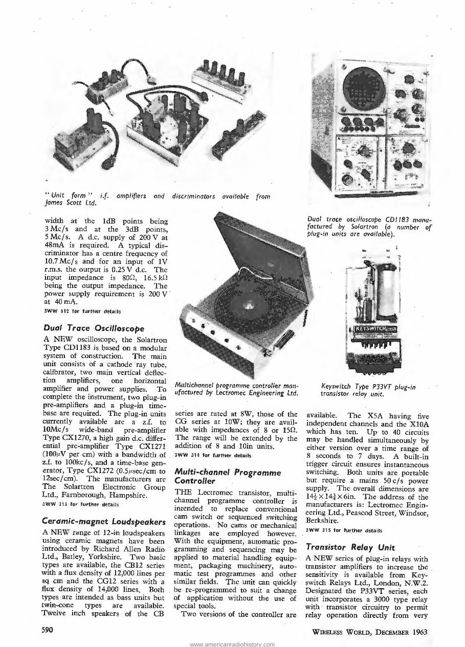
"Unit form " i.f. amplifiers and discriminators availal>le from James Scott Ltd.
width at the ldB points being 3 Mc/s and at the 3dB points, 5 Mcfs. A d.c. supply of 200 V at 48rnA is required. A typical discriminator has a centre frequency of 10.7 Mc/s and for an input of IV r.m.s. the output is 0.25 V d.c. The input impedance is 80D, 16.5 kfl being the output impedance. The power supply requirement is 200 V · at 40mA. 3WW 312 for further details
Dual Trace Oscilloscope A NEW oscilloscope, the Solartron Type CD1183 is baseq on a modular system of construction. The main unit consists of a cathode ray tube, calibrator, two main vertical deflection amplifiers, one horizontal amplifier and power supplies. To complete the instrument, two plug-in pre-amplifiers and a plug-in timebase are required. The plug-in units currently available are a z.f. to lOMe Is wide-band pre-amplifier Type CX1270, a high gain d.c. differential pre-amplifier Type CX1271 (100!-N per em) with a bandwidth of z.f. to lOOkc/s, and a time-base generator, Type CX1272 (O.S,u.secfcm to 12sec/cm)'. The manufacturers are The Solartron Electronic Group Ltd., Farnborough, Hampshire. 3 WW 31 3 for further details
Ceramic-magnet Loudspeakers A NEW range of 12-in loudspeakers using ceramic magnets have been introduced by Richard Allen Radio Ltd., Batley, Yorkshire. Two basic types are available, the CB12 series with a flux density of 12,000 lines per sq em and the CG 12 series with a flux density of 14,000 lines. Both types are intended as bass units but twin-cone types are available. Twelve inch speakers of the CB
590
Multichannel programme controller manufactured l>y Lectromec Engineering Ltd.
series are rated at 8W, those of the CG series at lOW; they are available with impedances of 8 or 150. The range will be extended by the addition of 8 and lOin units. JWW 314 for further details
Multi-channel Programme Controller THE Lectromec transistor, multichannel programme controller is intended to replace conventional cam switch or sequenced switching operations. ·No cams or mechanical linkages are employed however. With the equipment, automatic programming and sequencing may be applied to material handling equipment, packaging machinery, automatic test programmes and other similar fields. The unit can quickly be re-programmed to suit a change of application without the use of special tools.
Two versions of the controller are
Dual troce oscilloscope CD 1183 manufactured l>y Solartron (a number of plug~ in units are availal>le).
Keyswitch Type P33VT plug-in transistor relay unit.
available. The XSA having five independent channels and the XlOA which has ten. Up to 40 circuits may be handled simultaneously by either version over a time range of 8 seconds to 7 days. A built-in trigger circuit ensures instantaneous switching. Both units are portable but require a mains 50 c/s power supply. The overall dimensions are 14-!- X 14-i X 6in. The address of the manufacturers is: Lectromec Engineering Ltd., Peascod Street, Windsor, Berkshire. JWW 315 tor further details
Transistor Relay Unit A NEW series of plug-in relays with transistor amplifiers to increase the sensitivity is available from Keyswitch Relays Ltd., London, N.W.2. Designated the P33VT series, each unit incorporates a 3000 type relay with transistor circuitry to permit relay operation directly from very
WIRELESS WoRLD, DECEMBER 1963
Unit vrm " i.f. amplifiers and discriminators available from James Scott Ltd.
width at the IdB points being 3Mc/s and at the 3dB points, 5 Mc/s. A d.c. supply of 200 V at 48mA is required. A typical dis- criminator has a centre frequency of 10.7 Mc/s and for an nput of IV r.m.s. the output is 0.25 V d.c. The input impedance is 800, 16.5 kO b ng the output impedance. The power supply requirement is 200 V at 40 mA. 3WW 312 for further details
Dual Trace Oscilloscope
A NEW oscilloscope, the Solartron Type GDI 183 is basec} on a modular system of construction. The main unit consists of a cathode ray tube, calibrator, two main vertical deflec- tion amplifiers, one horizontal amplifier and power supplies To complete the instrument, two plug-in pre-amp fiers and a plug-in time- base are required. The olug-in units currently available are a z.f. to IGMc/s wice-band pre-amplifier Type CX1270, a I gh gain d.c. differ- en ial pre-amplifier Type CXI271 (lOC.uV per cm) with a bandwidth of z.f. to lOOkc/s, and a me-base gen- erator, Type CX1272 (0.5/isec/cm to 12sec/cm). Th^ manufacturers are The Solartron Electronic Group Ltd., Farnborough, Hampshire. 3WW 313 for further details
Ceramic-magnet Loudspeakers
A NEW range of 12-in loudspeakers using ceramic magnets have been ntroduced by Richard Allen Radio
Ltd., Batley, Yorkshire. Two basic types are available, the CB12 series \ ith a flux density of 12,000 lines per sq cm and the CGI 2 series with a flux density of 14,000 lines. Both types are (tended as bass units but twui-cone types are available. Twelve inch speakers of the CB
■ vx-:-;. ^ 3-1^ £
[j[!
Dual trace oscilloscope CDII83 manu- factured by Solartron (a number of plug-in units are available).
it ultichannel programme controller man- ufactured by Lectromec Engineering Ltd.
series are rated at 8W, those of the CG series at 10W, they are avail- able with impedances of 8 or 150. The range will be extended by the add ion of 8 and lOin units. 3WW 314 for further details
Multi-channel Programme Controller
THE Lectromec transistor, multi- channel programme controller is intended to replace conventional cam switch or sequenced switching operations. No cams or mechanical linkages are employed however. With the equ.pment, automatic pro- gramming and sequencing may be applied to material handling equip- ment, packaging machinery, auto- mate test programmes and other similar fields. The unit can quickly be re-programmed to suit a change of app1 cation without the use of special tools.
Two versions of the controller are
Key switch Type P33VT plug-in transistor relay unit.
available. The X5A having five independent channels and the X10A which has ten. Up to 40 circuits may be handled simultaneously by either version over a time range of 8 seconds to 7 days. A built-in trigger circuit ensures instantaneous switci ng. Both units are portable but require a mains 50c/s power supply. The overall dimensions are 14i X 14| X 6in. The address of the manufacturers is: Lectromec Engin- eering Ltd., Peascod Street, Windsor, Berkshire. 3WW 5 tor further details
Transistor Relay Unit
A NEW series of plug-in relays with transistor amplifiers to increase the sensitivity is available frt n Key- switch Relays Ltd., London, N.W.2. Designatet the P33VT series, each unit incorporates a 3000 type relay widi transistor circuitry to permit relay operation directly from very
590 Wireless World, December 1963
www.americanradiohistory.com

small input currents, the whole being mounted on a plug-in phenolic base. The complete relay can be enclosed in a metal or transparent cover. The power requirements of the relays are a switching or signal input and an a.c./d.c. supply voltage, the value of which depends on the type. Examples of applications of units in the series are, a relay initiated by a signal input of SJ1-A into an impedance of 2,000 to 10,0000, a relay operated by an audio signal from a microphone and a light-operated photocell relay unit. 3WW 316 for further details
Stereo Cartridge A NEW ceramic, turnover cartridge is announced by Cosmocord Ltd., Eleanor Cross Road, Waltham Cross, Hertfordshire. The unit is designed to track at 3gm a.nd is designated the "Acost·ereo 81." The output is approximately 100mV /em/sec and the frequency response extends from 30 to 15,000c/s±3dB.
The separation between channels is better than 15dB. Fitted with a diamond l.p./stereo stylus and a sapphir·e 78 r.p.m. stylus the unit costs £2 17s. With a sapphire l.p. stylus the price is £2 6s 6d. 1WW 317 for further details
Transistor Electronic Batch Counter , A BATCH counter using 4 decades with a maximum count of 9,999 has been produced by Thorh Electronics Ltd., Judd Street, London, W.C.l. The equipment can be wall-mounted or easily transported, the weight being only 9lb. It is fully compensated against wide fluctuations of mains supply and can operate in ambient temperatures of up to 40°C. When the count has reached the figure to which the unit has been set, a relay rated at 250V, 4A is operated: the counter then resets automatically.
The highest input frequency is 25kc/s, both sine and squarewave inputs are acceptable. The dimen..: sions of the equipment are 9 X 6 X Sin. 3WW 318 for further details
Instrument Cases A NUMBER of instrument cases of different sizes have been produced by West Hyde Developments Ltd. of Park Lane, Barefield, Middlesex. Designated the Cantil range, they are made in 21 s.w.g. steel with 18 s.w.g. front panels. Each front panel is fixed with four screws. Although this
WIRELESS WORLD, DECEMBER 1963
panel is recessed and mounted vertically, the outer-side edges of the case slope inward from top to bottom. Four loose feet are supplied with each case. The finish of the case is a hammer blue, the front panel being white. 3WW 319 for further details
Miniature Resistor A . RESISTOR 3.6mm long and 3.5mm in diameter rated at tW (20 °C) is available in a wide range of resistance values from Morganite Resistors Ltd., }arrow, Co. Durham. Designed primarily for use as a ballast resistor for low voltage neon lamps, a stability of better than 15 % is claimed provided that the maximum operating temperature of llOoC is not exceeded. 3WW 320 for further details
Power Triodes THO RIA TED tungsten filaments are employed in two new power triodes developed by the English Electric Valve Company, Chelmsford, Essex, for dielectric and radio frequency heating applications. The valves, Type B1152 and Bl153, when continuously operated with forced-air cooling systems have
" Acostereo 81 " ceramic, turnover, stereo cartridge.
Above: Conti/ instrument case ·manufactured by West Hyde Developments.
Right: Type GM5605 X-Y oscilloscope from Research and Control Instruments Ltd.
anode dissipations of 500 and 800 W respectively. For low duty cycle operation, these may be increased to 1,000 W and 1,500 W respectively. Both types can be operated to full ratings at frequencies up to 50 Mc/s. The manufacturers claim that for each type, the variation of electrical parameters from valve to valve is much less than previously attainable. This reduces considerably circuit adjustments when valves are changed. The Bll52 and the Bll53 draw 32.5A filament current, the former, however, is at 5 V while the latter is 6.3. The overall length of the '52 is 9.45in with a diameter of 5.12in, while the . dimensions of the '53 are 9.9 and 6.10in. 3WW 321 for further details
X-Y Oscilloscope A COMPACT oscilloscope using a 3-in diameter tube and having identical x and y amplifiers is available from Research and Control Instru- . ments Ltd., King's Cross Road: London, W .C.l. This instrument, the Type GM5605 manufactured by Philips, has a frequency range of z.f. to 200kc/s, the phase difference between the outputs of the two amplifiers 'being less than 3 degrees. The c.r.t. graticule is divided .into 6-mm
The Thorn CB.22 electronic batch counter.
591
small input currents, the whole being mounted on a plug-in phenolic base. The complete relay can be enclosed in a metal or transparent cover. The power reqi rements of the relays are a switching or signal input and an a.c./d.c. supply voltage, the value of which depends on the type. Examples of applications of units in the series are, a relay initiated by a signal input of 5/j.A into an tnpe- dance of 2,000 to 10,000^, a relay operated by an audio signal from a microphone and a light-operated photocell relay unit. 3WW 316 for further details
Stereo Cartridge
A NEW ceramic, turnover cartridge is annotmced by Cosmocord Ltd., Eleanor Cross Road, Waltham Cross, Hertfordshire. The unit is designed to track at 3gm and is designated the "Acostereo 81." The output is approximately lOumV/cm/sec and the frequency response extends from 30 to 15,000 c/s + 3dB.
The separation between channels is better than 15dB. Fitted with a diamond l.p./stereo stylus and a sapphire 78 r.p.m. stylus the unit costs £2 17s. With a sapphire l.p. stylus the price is £2 6s 6d. 1WW 317 for further details
Transistor Electronic Batch Counter ,
A BATCH counter using 4 decades with a maximum count of 9,999 has been produced by Thorii Electronics Ltd., Judd Street, London, W.C.I. The equipment can be wall-mounted or easily transported, the weight be- ing only 91b. It is fully compensated against wide fluctuations of mains supply and can operate in ambient temperatures of up to 40 0C. When the count has reached the figure to which the unit has been set, a relay rated at 250V, 4A is operated: the counter then resets automatically.
The highest input frequency is 25kc/s, both sine and squarewave inputs are acceptable. The ( men- sions of the equipment are 9 X 6 X Sin. 3WW 318 for further details
Instrument Cases
A NUMBER of instrument cases of different sizes have been produced by West Hyde Developments Ltd. of Park Lane, Harefield, Middlesex. De- signated the Con I range, they are made in 21 s.w.g. steel v th 18 s.w.g. front panels. Each front panel is fixed with four screws. Although this
panel is recessed and mounted verti- cally, the outer-side edges of the case slope inward from top to bottom. Four loose feet are supplied with each case. The finish of the case : s a hammer blue, the front panel be- ing white. 3WW 319 for further details
Miniature Resistor
A , RESISTOR 3.6mm long and 3.5mm in diameter rated at iW (20 °C) is available in a wide range of resistance values from Morganite Resistors Ltd., Jarrow, Co. Durham. Designed primarily for use as a bal- last resistor for low voltage neon lamps, a stability of better than 15% is claimed provided that the maxi- mum operating temperature of 110°C is not exceeded. 3WW 320 for further details
Power Tnodes
THORIATED tungsten filaments are employed in two new power triodes developed by the English Electric Valve Company, Chelms- ford, Essex, for dielectric and radi i frequency heating applications. The valves. Type B1152 and B1153, when cont luously operated with forced-air cooling systems have
"Acostereo 81" ceramic, turnover, MS stereo cartridge. mmM
anodi dissipations of 500 and 800 W respectively. For low duty cycle operation, these may be increased to 1,000 W and 1,500 W respec- tively. Both types can be operated to full ratings at frequencies up to 50Mc/s. The manufacturers claim that for each type, the variation of electrical parameters from valve to valve is much less than previously attainable. This reduces consider- ably circu adjustments when valves are changed. The B1152 and the B1153 draw 32.5A filament current, the former, however, is at 5 V while the latter is 6.3. The overall length of the '52 is 9.45in w..h a diameter of 5.12in, while the. dimensions of the '53 are 9.9 and 6.10in. 3WW 321 for further details
X-Y Oscilloscope
A COMPACT oscilloscope using a 3-in diameter tube and having : len- tical x and y amplifiers is available from Research and Control Instru-, ments Ltd., King's Cross Road, London, W.C.I. This instrument, the Type GM5605 manufactured by Philips, has a frequency range of z.f. to 200kc/s, the phase difference between the outputs of the two ampli- fiers being less than 3 degrees. The c r.t. graticule is divided .into 6-mm
The Thorn CB.22 electronic batch counter.
Above: Cont'd instrument case manufactured by West Hyde Developments.
Right: Type CM5605 X-Y oscilloscope from Research and Control Instruments Ltd.
.. s-^y-v.,. I
wmm v!<.
" % s
-A?- 4
Wireless World, December 1963 591
www.americanradiohistory.com

divisions and although the amplifiers are equal, the overall vertical sensitivity is 10mV per division, the overall horizontal sensitivity being 30m V per division. Both sweeps may be expanded up to 3 times. The sensitivity on each axis can be reduced to 30V per division by step attenuators and continuous gain controls.
The timebase has a sweep speed variable between 0.02 and lOOmsec per scale division. Internal or external triggering may be employed, trigger level is adjustable.
Mains operated, the instrument weighs 22lb and measures 10 X 6-t X 13-tin. The price is £85. 3ww 322 for further details
Electron Spin Resonance Kit ELECTRON spin resonance is the term applied to the absorption of radio frequency energy by molecules which have an unpaired electron. The E.S.R. kit No. A12 manufactured by Scientifica, St. Dunstan's Avenue, Acton, London, W.3, when assembled, operates over a frequency range of 50 to 140 Mcls depending upon the detector coil inductance. Samples being investigated are placed inside this coil and absorb radio frequency energy at resonance. This enables the instrument to be used for detection of free
-1J
radicles in many common materials such as cupic sulphate, ultramarine, coal and tar; the sensitivity being 10 1 7 unpaired electrons. The use of an additional phase-sensitive detector amplifier increases this to 101
J . Other applications include the measurement o~ t:he magnetic moment of an electron and the elm ratio.
If required for use in educational . spheres the apparatus can be repeatedly assembled and dismantled by successive groups of students. The kit as supplied, includes everything necessary to build the apparatus with the exception of the connecting wire. The price is £33 . A general purpose oscilloscope can be driven from the instrument. 3WW 323 for further details
Phase-sensitive Detector THE low zero drift is a noteworthy feature of the PD629 phase sensitive detector. After one hour this is quoted as being 0.05% of f.s.d. per hour. The linearity is such that no intermodulation product will exceed 0.1 % of f.s.d. under normal operating conditions. The frequency range of the instrumen'!" is 1 Oc Is to 1 OOkc Is, the amplitude of the reference input being 2V r.m.s. sine wave or 6V peakto-peak for square wave. The signal
;p u ~~J ),($,):. ,,,.
< ,
l t ' .l
-~
A/Jove: Brookdea/ Model PD.629 general purpose, phase-sensitive detector .
U.h.f. television /Jution amplifier developed /Jy Teleng Ltd., for showroom use.
' 592
w --.. .
·~
~
"'""'
~
" Printact " relays mounted on a glass epoxy printed /Joard.
input requirement is up to 6V peakto-peak. The input impedance of both channels is O.SMD, lOpF.
The equipment is particularly useful as a detector for a.c. bridges, because with a switched reference phase it can independently show resistive and reactive nulL When required for optical or infra-red spectrometer work a modified instrument can be obtained so that a photo-diode may be connected. The manufacturers are JJrookdeal Electronics Ltd., Lewisham, London, S.E.l3. 3WW 324 for further details
(;J.H.F. ·Television Signal Distribution U.H.F. television signal distribution kits consisting of amplifiers, splitters, cables, clips and outlet boxes are available from Teleng Ltd., Romford, Essex. Kits are available for 6, 12 or 24 outlets and each system has amplifier gain such that the signal strength at each outlet is never less than that available at the aerial downlead. The amplifiers are mains powered and have gains of 20, . 30 or 40dB. The channel bandwidth is 10 Mcls (-3dB). 3WW 325 for further details
Print ed Circuit Relay THE " Printact " relay uses a printed circuit board to supply the stationary portion of the contact assembly. The unit was designed for direct mounting on printed boards. The armature and moving contact assembly consists of a No. 5 relay steel armature, a Mylar insulator, a . high-impact plastic moulding and heat treated beryllium-copper springs with bar palladium contacts.
The ohly moving part, the contactcarrying armature assembly, is held in position against the edge of a U-shaped fixed magnetic member by a small ceramic permanent magnet. When the relay is energized, the electromagnetic field so produced, opposes the field of the permanent magnet causing the armature to rotat.e. For operating voltages of 6, 12 . an.d 24V d.c. the coil resistances are 75,300 and 1,2000 respectively. ( ± 10 %.) The power consumption is SOOmW. The maximum ambient temperature at which the
. relays can be used is 70°C. At the stipulated voltage the operating time for the units is 10msec. The relays weigh 0.8oz each and the dimensions are i Xi X :~in. They are distributed in the U.K. by A. D. S. Relays; Ltd., St. John Street, E.C.l. 3WW 326 for further details
WIRELESS WORLD, DECEMBER 1963
divisions and although the amplifiers are equal, the overall vertical sensi- tivity s XOmV per r T ision, the over- all horizontal sen; ;y being 3dmV per dh is on. lloth sweeps may be exparied up to 3 t' nes. The sensi- tivity on each axis can be reduced to 30V per d' /ision by step attenuators and con tiuous gain controls.
The timebase has a sweep speed variable between 0.02 and 100msec per scale d hsion. Internal or ex- ternal triggering may be employed: t igger level is adjustable.
Mains operated, the instrument weighs 221b and measures lOxb^X IS^in. The price is £85. iJWW 322 for further details
Electron Spin Resonance Kit
ELECTRON spin resonance is the term apphed to the absorption of radio frequency energy by molecules which have an unpaired electron. The E.S.R. k: No. A12 manufac- tured by Scientifica, St. Dunstan's Avenue, Acton, London, W.3, when assembled, operates over a frequency range of 50 to 140 Mc/s depending upon the detector col; inductance. Samples be; ig investigated are placed inside this coil and absorb radio frequency energy at reson- ance. This enables the instrument to be used for detection of free
radicles a many common materials such as cupic sulphate, ultramarine, coal and tar; the sensitivity being 1017 unpaired electrons. The use of an additional phase-sensitive de- tector amplifier increases this to 1013. Other applications include the measurement of the magnetic moment of an electron and the e/m ra o.
If required for use in educational, spheres the apparatus can be repeat- edly assembled and dismantled by successive groups of students. The kit as supplied, includes everything necessary to build the apparatus with the exception of the connecting wire. The price is £33. A general purpose os< loscope can be driven from the instrument. 3WW 323 for further details
Phase-sensitive Detector
THE low zero drift is a noteworthy feature of the PD629 phase sensitive detector After one hour this is quoted as being 0.05% of f.s.d. per hour. The 1." earity is such that no intermodulation product will exceed 0.1% of f.s.d. under normal operating conditions. The frequency range of the istrument' is lOc/s to lOOkc/s, the amplitude of the reference input being 2V r.m.s. sine wave or 6V peak- to-peak for square wave. The signal
Above: Brookdea! Model PD.629 general purpose, phase-sensitive detector.
" Printact " relays k mounted on a glass
*0 ' jL epoxy printed board.
pr (i " '■
U.h.f. television distri- ' bution amplifier devel- oped by Teleng Ltd., for showroom use.
m- «(y
input requirement is up to 6V peak- to-peak. The " iput impedance of both channels is 0.5MO, 10pF.
The equipment is particularly use- ful as a detector for ax. bridges, be- cause v th a switched reference phase it can independently show resistive and reactive null. When required for optical or infra-red spectrometer work a modified istrument can be
■ obtained so that a photo-diode may be connected. The manufactu :ers are Brookdea! Electronics Ltd., Lew ham, London, S.E.13. 3WW 324 for further details
U.H.F. Television Signal Distribution
J.H.F. television- signal distribution kits consisl ig of amplifiers, splitters, cables, clips and outlet boxes are available from Teleng Ltd., Rom- ford, Essex. Kits are available for 6, 12 or 24 outlets and each system has amplifier gain such that the signal strength at each outlet is never less than that available at the aerial downlead. The amplifiers are mains powered and have gains of 20, 30 or 40dB. The channel bandwidth is 10Mc/s (—3dB). 3WW 325 for further details
Pri ted Circuit Relay
THE " Printact" relay uses a printed circu't board to supply the stationary portion of the contact assembly. The unit was designed for direct mount- ing on printed boards. The arma- ture and moving contact assembly consists of a No. 5 relay steel arma- ture, a Mylar insulator, a high-im- pact plastic moulding and heat treated beryl um-copper springs with bar palladium contacts.
The only moving part, the contact- carrying armature assembly, is held in position against the edge of a U-shaped fixed magnetic member by a small ceramic permanent mag- net When the relay is energized, the electromagnetic field so pro- duced, pposes the field of the per- manent.magnet causing the armature to rotate. For operating voltages of 6, 12 and 24V d.c. the cc. [ resist- ances are 75,300 and 1,20012 respec- tively. ( + 10%.) The power con- sumption is 500mW. The maximum ambient temperature at which the relays can be used is 70 "C. At the stipulated voltage the operating time for the units is 10msec. The relays weigh 0.8oz each and the dimen- sions are | X | X jfin. They are dis- tributed in the U.K. by A. D. S. Relays Ltd., St. John Street, E C.l 3WW 326 for further details
592 Wireless World, December 1963
www.americanradiohistory.com

These Advanced Features give the Vanguard EXTRA PERFORMANCE UNIT PRINTED BOARD CIRCUIT ELEMENTS
SEALED BLOCK I.F. FILTERS Need no tuning
IN T R 0 D U C E. THE
VANGUARD .A Mag n ifi cent
2s-watt Transistorised
·RADIOTELEPHONE ONLY the VANGUARD has ALL these qualities
'
• 25/30 & 50/60Kc/s channels • Dust-proof and splash-proof
• Extensively Transistorised - • One-Six Channels
• Sealed Block I.F. Filters • 25 Watts Output
• Printed Circuitry • Very low-noise Receiver
• Very low Battery Drain • High Stability Mute
• All Aluminium Construction • 4 Watts Audio Output -
Meets British, American, Canadian and Continental Specifications
PVE. TELECOMMUNICATIONS LIMITED I I I CAMBRIDGE 3WW--111 FOR FURTHER DETAILS.
> ' ir / . '
es g :ORI\
m I
s
SE BLOCK I. Need no
INTRODUCE THE
VANGUARD
A Magnificent
25-watt Transistorised
RADIOTELEPHONE
ONLY the VANGUARD has ALL these qualities
25/30 & 50/60Kg/s channels
Extensively Transistorised
Sealed Block I.E. Filters
Printed Circuitry
Very low Battery Drain
All Aluminium Construction
• Dust-proof and splash-proof
• One—Six Channels
• 25 Watts Output
• Very iow-noise Receiver
• High Stability Mute
• 4 Watts Audio Output
Meets British, American, Canadian and Continental Specifications
PYE TELECOMMUNICATIONS LIMITED... CAMBRIDGE
3WW—111 FOR FURTHER DETAILS.
www.americanradiohistory.com

74 WIRELESS WORLD DECEMBER, 1963
10 mVjcm: type P.M 3201 ~
N!IIW PHILIPS OSCILLOSCOPES
Main specification PM 3201
sensitivity and bandwidth 10 mV jcm from D.C. - 1 Mcjs 50 mV jcm - 5 V jcm from D.C. - 5 Mcjs
accuracy 3% sweep speeds (in 18 cali- 0.5 p, sec/em - 200 msecjcm brated steps and continuous) magnification 5x trigger facilities int + and -, ext + and -,mains freq. + and -cathode ray tube 10 em ( 4 in.). 2.8 kV acc.volt additional features built-in calibration voltage for probe adjustment accessories supplied attenuator probe, cables , viewing hood
2 mV fern: type PM 3206
PM 3206
2 mV jcm from D.C. - 100 kc/s 10 mV jcm- 50 V jcm from D.C.- 300 kcjs 3% 2p, secjcm -1 sec/em
5x int + and-, ext+ and -,. mains freq . + and -10 em ( 4 in.). 2.8 kV ace. volt built -in calibration voltage ' connector cables
Optional accessories and auxiliary instruments for Philips oscilloscopes:
High precision Standard Multi -purpose ; Trigger delay Electronic Pre-amplifier ProJection lens Extra Proljes Recording ) Recording photographic Unit GM 4585 Switch PP 1071 PM 6041 PM 9301 Camera PP 1021 Camera PP 1014 equipment
PM 9300 · .
PHILIPS
e PHILIPS electronic measuring instruments
Sales ami Service all over the world Sole distributor for the U.K. : Research and Control Instruments L.td., 207 Kings Cross Road, LONDON WCt For the Republic of Ireland: Philips Electrical (Ireland) L.td., NewsteaQ, Clonskeagh, DUBLIN Overseas enquiries please, to the manufacturers, Philips, Ema Department, EINDHOVEN, Hollan"
lWW-112 FOR FURTHER DETAILS.
74 Wireless World December, 1963
W-
mm.
§ § 9 ^ |(p
#i ^ §
10 mV/cm: type PM 3201
NEW PHILIPS OSCILI OSCOPES
■ <— 1
ii
8^K- «Ssfe
ii -1:. .
> >m. SMSct- '
2 mV/cm: type PM 3206
v«cvt^ f-flftisgp; ^ o d o
Main specification
sensitivity and bandwidth 10 mV/cm from D.C. - 1 Mc/s 50 mV/cm - 5 V/cm from D.C. - 5 Mc/s
accuracy 3% iweep speeds (in 18 cali- 0.5yMsec/cm - 200 msec/cm
brated steps and continuous) magnification 5x trigger facilities int + and ext + and -.mains freq. + and - cathode ray tube 10 cm (4 in.), 2.8 kV acc.volt
PM 3201
additional features accessories supplied
PM 3206
2 mV/cm from. D.C. - 100 kc/s 10 mV/cm - 50 V/cm from D.C. - 300 kc/s 3% 2ju sec/cm -1 sec/cm
5x int + and ext + and -..mains freq. + and 10 cm (4 in.), 2.8 kV acc.volt
built-in calibration voltage for probe adjustment built-in calibration voltage ' attenuator probe, cables, viewing hood connector cables
Optional accessories and auxiliary instruments for Philips oscilloscopes.
fHR i iLmW-'] : IT 8.'
BE iA •„
High precision Recording > Camera PP1021
Standard Recording Camera PP 1014
Multi-purpose fc photographic equipment PM 9300
if
i i1 i f
Trigger delay Unit GM 4585
Electronic Switch PP 1071
\V»J
.Pre-amplifler' PM 6041
Projection lens PM 9301
Extra Proljes
PHILIPS
electronic measuring instruments Sales and Service all over the world Sole distributor for the U.K.: Research and Copt'H instruments Ltd., 207 Kings Cross Road, LONDON WCt For the Republic of Ireland: Philips Electrical (Ireland) Ltd., Newstea^, Clonskeagh, DUBLIN Overseas enquiries please, to the manufacturers, Philips, Ema Department, EINDHOVEN, Holland
awW—112 FOR FURTHER DETAILS. www.americanradiohistory.com

NEW LOW-NOISE TRANSISTOR CIRCUIT FOR ELECTROSTATIC MICROPHONES
Measurements of Frequency Response, Linearity, . Noise and Sensitivity
(Concluded from page 542 of the November issue)
I T is important to distinguish between the frequency response of the microphone element itself, and the frequency response of the associated circuit.
To measure the circuit frequency response, one wants, in effect, to cause one of the two capacitances in the r.f. bridge to vary, at audio frequency, uniformly throughout the audio band. This, fortunately, is quite easy to do, by exploiting the fact that the capacitance of a back-biased junction diode is voltage dependent.
The circuit arrangement employed is shown in Fig. 6. The two 0.5pF capacitors and the diode form a capacitive potential divider network which feeds an additional reactive current to the bridge output point, the magnitude of this current being varied at audio frequency by the changing diode
· capacitance. The effect is just the same as if one of the normal bridge capacitances was varied at audio frequency.
The frequency response obtained in this manner was well within ± 1 dB over the whole audio spectrum, up to 15 kc/s, on open circuit, on short circuit or on a 600-ohm resistive load.
It was interesting to observe that, when using a valve amplifier with a 1: 10 input transformer, unloaded on the secondary side, the response was about 0.5 dB up at 10 kc/s but had returned to its lowfrequency level again at 15 kc/s, whereas this same amplifier when fed from a resistive 600 ohm source showed no rise and was 0.5 dB down at 15 kc/s. This is due to the effect of the series inductive com-
VARIABLE CAPACITANCE
DIODE (APPROX.25p)
I·SV
82k
.AUDIO OSCILLATOR
Fig. 6. Set-up for circuit frequency-response measurement.
WIRELESS WORLD, DECEMBER 1963
By P. J. BAXANDALL, a.sc.(Eng.) ,
ponent of the output impedance of the microphone circuit in association with the shunt capacitance of the transformer. If desired the microphone output impedance could be rendered more purely resistive by the addition of a suitable series combination of C and R across the output terminals.
The frequency response of the complete system, including the microphone element, for a constant alternating pressure on the diaphragm, may be obtained in the manner shown in Fig. 7.
The centre tap of the bridge transformer, instead of being directly earthed, is here earthed at r.f. only, via a capacitor. A d.c. polarizing voltage, from a battery, is applied, and on this is superimposed an
lk
3,300p AUDIO
OSCILLATOR
TO PREVENT DIRECT
AUDIO TRANSFER
Fig. 7. Set-up far overall frequency-response measurement.
audio voltage from an oscillator. The d.c. polarizing voltage causes a force of attraction between the dia-· phragm and the back electrode, and the effect of the very much smaller audio voltage is to cause this force to vary almost perfectly sinusoidally at the oscillator frequency. This results in an audio output from the microphone circuit just as if the diaphragm were actuated by a constant acoustic alternating pressure.
In practice it was found desirable, however, to take one precaution, which was to add, temporarily, a small choke (about 100 ,uH) to earth at ~he phasesensitive rectifier input, as shown in Fig. 7. Without this, there was significant direct transfer of audio frequency signals at high audio frequencies, which gave misleading results.
Fig. 8 shows the frequency response obtained
593
NEW LOW-NOISE TRANSISTOR CIRCUIT FOR
ELECTROSTATIC MICROPHONES
Measurements of Frequency Response, Linearity, Noise and Sensitivity
(Concluded from page 542 of the November issue) By P. J. BAXANDALL, B.Sc.(Eng.)
1.T is important to distinguish between the fre- quency response of the microphone element itself, and the frequency response of the associated circuit.
To measure the circuit frequency response, one wants, in effect, to cause one of the two capacitances in the r.f. bridge to vary, at audio frequency, uniformly throughout the audio band. This, fortunately, is quite easy to do, by exploiting the fact that the capacitance of a back-biased junction diode is voltage dependent.
The circuit arrangement employed is shown in Fig. 6. The two 0.5pF capacitors and the diode form a capacitive potential divider network which feeds an additional reactive current to the bridge output point, the magnitude of this current being varied at audio frequency by the changing diode capacitance. The effect is just the same as if one of the normal bridge capacitances was varied at audio frequency.
The frequency response obtained in this manner was well within + 1 dB over the whole audio spec- trum, up to 15 kc/s, on open circuit, on short circuit or on a 600-ohm resistive load.
It was interesting to observe that, when using a valve amplifier with a 1:10 input transformer, un- loaded on the secondary side, the response was about 0.5 dB up at 10 kc/s but had returned to its low- frequency level again at 15 kc/s, whereas this same amplifier when fed from a resistive 600 ohm source showed no rise and was 0.5 dB down at 15 kc/s. This is due to the effect of the series inductive com-
ponent of the output impedance of the microphone circuit in association with the shunt capacitance of the transformer. If desired the microphone output impedance could be rendered more purely resistive by the addition of a suitable series combination of C and R across the output terminals.
The frequency response of the complete system, including the microphone element, for a constant alternating pressure on the diaphragm, may be obtained in the manner shown in Fig. 7.
The centre tap of the bridge transformer, instead of being directly earthed, is here earthed at r.f. only, via a capacitor. A d.c. polarizing voltage, from a battery, is applied, and on this is superimposed an
rj-i l± > lTTJ
microphone
; TO PREVENT . DIRECT 'AUDIO TRANSFER
AUDIO OSCILLATOR
r-l-i MICROPHONE'^ SI! j
TO PHASE-SENSITIVE
RECTIFIER
0'5p 0*5 p
VARIABLE CAPACITANCE __
DIODE -- (APPR0X.25p) .
+ OSCILLATOR
Fig. 6. Set-up for circuit frequency-response measurement.
Fig. 7. Set-up for overall frequency-response measurement.
audio voltage from an oscillator. The d.c. polarizing voltage causes a force of attraction between the dia- phragm and the back electrode, and the effect of the very much smaller audio voltage is to cause this force to vary almost perfectly sinusoidally at the oscillator frequency. This results in an audio output from the microphone circuit just as if the diaphragm were actuated by a constant acoustic alternating pressure.
In practice it was found desirable, however, to take one precaution, which was to add, temporarily, a small choke (about 100 /jlH) to earth at fhe phase- sensitive rectifier input, as shown in Fig. 7. Without this, there was significant direct transfer of audio frequency signals at high audio frequencies, which gave misleading results.
Fig. 8 shows the frequency response obtained
Wireless World, December 1963
www.americanradiohistory.com

using the Fig. 7 set-up. This is, of course, a rather poor frequency response for a microphone, but the reader will not be surprised at this on hearing that the microphone element used for these experiments is of pre-war vintage !
Microphone Characteristics It is interesting to consider the main features of the Fig. 8 response curve. The main resonance occurs at 7.3 kc/s, and is very underdamped. There is also evidence of a higher-frequency resonant mode at just over 10 kc/s . The gradual change in response at lower frequencies is thought to be probably due -to a changeover from isothermal to adiabatic operation of the air behind the diaphragm with rising frequency. Most of the diaphragm stiffness in this design appears to be provided by the air behind the diaphragm rather than by the diaphragm tension, so that one would expect the stiffness at low audio frequencies to be less than that at higher frequencies by a factor equal to the ratio of the specific heat of air at constant pressure to that at constant volume. This ratio is 1.4, and would give a change in response of approximately 3 dB, which is, in fact, about what is observed.
The response curve of Fig. 8 may be taken, with slight reservations, to be the response curve of the microphone as normally used. The reservations are concerned with the fact that the method of measurement does not take into account diffraction effects at high frequencies (ref. 4), where the dimensions of the microphone element are not negligible compared with a wavelength, nor does it take into account the possibility of acoustical or mechanical resonances in the microphone casing. However, in view of the very small size of the omnidirectional element here used, and the unobstructive nature of the wire-me3h casing, these effects would be expected to be small.
To improve the sound quality obtainable, an equalizer circuit was added to the microphone amplifier to compensate for both the resonant peak and the smooth change in level at lower frequencies . The overall response is then level, within ± 2 dB, up to 12 kc/s.
Audibly, the main effect of adding the equalizer is to remove the excessive sibilants on speech, leaving the reproduction smooth and pleasant-not lacking top, but without its previous artificial rustle and glitter. Various recordings which have been made with the equalized microphone, of piano, harpsichord, organ, brass band and choir, have led to the belief that, for an omnidirectional -microphone, the performance leaves little if anything to be desired.
Linearity Measurements The amplitude linearity may be investigated in a very simple manner, because this microphone system has a response extending down to zero frequency. All one has to do is to change the capacitance on one side of the bridge circuit by small known amounts and measure the d.c. output by means of a meter across the output terminals.
The result of such a measurement, with a 600-ohm load on the output, is shown in Fig. 9. An equally good characteristic was obtained with the microphone on open circuit, but on measuring the output current with almost zero load resistance, a slight trace of non-linearity was observable at the extreme limits of the curve.
·10
5
dB ·o
-5
-10 o·re o·os o·r
~
o·s r ' 5 10 FREQUENCY ( kc fs)
Fig. 8. Overall frequency response of microphone system, without equalization.
It should be emphasized that under almost all conditions of use only an extremely small part of the Fig. 9 characteristic is traversed. Ordinary conversational speech at a foot or two corresponds to about 1 dyne/cm 2 alternating pressure, and this causes, with a typical modern electrostatic microphone element, a capacitance change in the region of 0.001 pF. Such a small capacitance change is virtually invisible on the scale to which Fig. 9 is plotted.
The small capacitance changes required for determining the Fig. 9 characteristic were obtained by means of a small Philips concentric (" milkcan ") trimmer. A fine pencil mark was made on the rotor of this, a series of such marks being made on the stator. The capacitance with the rotor mark opposite each stator mark was then determined on a capacitance bridge; the capacitor, thus calibrated, was returned to the microphone circuit.
Noise Measurements The results of some measurements made to determine the noise performance of the microphone circuit are shown in Fig. 10. For these measurements the microphone element was replaced by a trimmer, so as to avoid acoustically picked up noise and mechanical thermal noise generated within the element. The noise (unweighted) was measured using a low-noise valve amplifier, thermocouple and galvanometer, over a bandwidth (determined by sharp-cutting filters) extending from approximately 400c/s to 15kc/s.
From the top curves in Fig. 10 it will be seen that the noise is very dependent on the degree of unbalance of the bridge circuit, particularly when the oscillator is operated with the transistor not bottoming. This is quite reasonable, because the effect of allowing the collector to bottom is to clamp the tuned circuit voltage to a well-determined amplitude once per cycle. When there is no bottoming, the amplitude is free to wander about in a random manner, under the influence of transistor and thermal noise, -giving rise to greatly increased "a.m. noise".
Curve B in Fig. 10 (a) has been plotted, it will be seen) on a decibel scale, OdB representing the noise output which would be produced if the only source of noise were Johnson noise in the 600-ohm resistive component of the microphone output impedance. ·
In Fig. 10 (b), the same curve has been replotted on a different basis-the vertical quantity here is really the extra noise voltage resulting from unbalancing the bridge. This discloses the true nature of the effect; all that is happening is that, as the bridge is more and more unbalanced, more and
WIRELESS WORLD, DECEMBER 1%3
using the Fig. 7 set-up. This is, of course, a rather poor frequency response for a microphone, but the reader will not be surprised at this on hearing that the microphone element used for these experiments is of pre-war vintage!
Microphone Characteristics
It is interesting to consider the main features of the Fig. 8 response curve. The main resonance occurs at 7.3 kc/s, and is very underdamped. There is also evidence of a higher-frequency resonant mode at just over 10 kc/s. The gradual change in response at lower frequencies is thought to be probably due to a changeover from isothermal to adiabatic opera- tion of the air behind the diaphragm with rising frequency. Most of the diaphragm stiffness in this design appears to be provided by the air behind the diaphragm rather than by the diaphragm tension, so that one would expect the stiffness at low audio frequencies to be less than that at higher frequencies by a factor equal to the ratio of the specific heat of air at constant pressure to that at constant volume. This ratio is 1.4, and would give a change in response of approximately 3 dB, which is, in fact, about what is observed.
The response curve of Fig. 8 may be taken, with slight reservations, to be the response curve of the microphone as normally used. The reservations are concerned with the fact that the method of measure- ment does not take into account diffraction effects at high frequencies (ref. 4), where the dimensions of the microphone element are not negligible compared with a wavelength, nor does it take into account the possibility of acoustical or mechanical resonances in the microphone casing. However, in view of the very small size of the omnidirectional element here used, and the unobstructive nature of the wire-mesh casing, these effects would be expected to be small.
To improve the sound quality obtainable, an equalizer circuit was added to the microphone amplifier to compensate for both the resonant peak and the smooth change in level at lower frequencies. The overall response is then level, within ± 2 dB up to 12 kc/s. ' '
Audibly, the main effect of adding the equalizer is to remove the excessive sibilants on speech, leaving the reproduction smooth and pleasant—not lacking top, but without its previous artificial rustle and glitter. Various recordings which have been made with the equalized microphone, of piano, harpsi- chord, organ, brass band and choir, have led to the belief that, for an omnidirectional microphone, the performance leaves little if anything to be des'ired.
Linearity Measurements
The amplitude linearity may be investigated in a very simple manner, because this microphone system has a response extending down to zero fre- quency. All one has to do is to change the capacit- ance on one side of the bridge circuit by small known amounts and measure the d.c. output by means of a meter across the output terminals.
The result of such a measurement, with a 600- ohm load on the output, is shown in Fig. 9. An equally good characteristic was obtained with the microphone on open circuit, but on measuring the output current with almost zero load resistance, a slight trace of non-linearity was observable at the extreme limits of the curve.
394
•10 — - —
jiimi iiiiiiiii rfh'fi 0-03 (TOS o7] 0-5 I .5 10
FREQUENCY (kc/s)
Fig. 8. Overall frequency response of microphone system, without equalization.
It should be emphasized that under almost all conditions of use only an extremely small part of the Fig. 9 characteristic is traversed. Ordinary con- versational speech at a foot or two corresponds to about 1 dyne/cm2 alternating pressure, and this causes, with a typical modern electrostatic micro- phone element, a capacitance change in the region of 0.001 pF. Such a small capacitance change is virtually invisible on the scale to which Fig. 9 is plotted.
The small capacitance changes required for deter- mining the Fig. 9 characteristic were obtained by means of a small Philips concentric (" milkcan") trimmer. A fine pencil mark was made on the rotor of this, a series of such marks being made on the stator. The capacitance with the rotor mark opposite each stator mark was then determined on a capacitance bridge; the capacitor, thus calibrated, was returned to the microphone circuit.
Noise Measurements
The results of some measurements made to deter- mine the noise performance of the microphone circuit are shown in Fig. 10. For these measure- ments the microphone element was replaced by a trimmer, so as to avoid acoustically picked up noise and mechanical thermal noise generated within the element. The noise (unweighted) was measured using a low-noise valve amplifier, thermocouple and galvanometer, over a bandwidth (determined by sharp-cutting filters) extending from approximately 400 c/s to 15 kc/s.
From the top curves in Fig. 10 it will be seen that the noise is very dependent on the degree of unbalance of the bridge circuit, particularly when the oscillator is operated with the transistor not bottoming. This is quite reasonable, because the effect of allowing the collector to bottom is to clamp the tuned circuit voltage to a well-determined amplitude once per cycle. When there is no bottoming, the amplitude is free to wander about in a random manner, under the influence of tran- sistor and thermal noise, giving rise to greatly increased "a.m. noise".
Curve B in Fig. 10 (a) has been plotted, it will be seen, on a decibel scale, OdB representing the noise output which would be produced if the only source of noise were Johnson noise in the 600-ohm resistive component of the microphone output impedance.
In Fig. 10 (b), the same curve has been replotted on a different basis-—the vertical quantity here is really the extra noise voltage resulting from un- balancing the bridge. This discloses the true nature of the effect; all that is happening is that, as the bridge is more and more unbalanced, more and
Wireless World, December 1963
www.americanradiohistory.com

more noise trom the oscillator IS let through, in direct proportion to the degree of unbalance.
Phase-sensitive Rectifier Noise:-It will be seen from
Fig. 10 that, with the bridge perfectly balanced,
there is more noise when the oscillator is bottoming than when it is not bottoming.
Now the absence of bottoming, achieved by suitably increasing the oscillator emitter resistance, is accompanied by a reduction in the oscillator output voltage and hence in the reference voltage fed to the phase-sensitive rectifier. It seems, therefore, that some of the observed noise is generated by the phasesensitive rectifier transistors and that this noise is reduced if the reference voltage is reduced.
An independent test, in which the reference voltage was varied by other means, also showed a reduction in noise output for a decrease in reference voltage.
At first sight, since a reduction in reference voltage will make the switching operation slower, i.e., less nearly ideal, one might well expect a poorer, rather than a better, noise performance.
In an entirely separate experiment, a 600-ohm resistor wa's connected across the primary of the input transformer of a low-noise audio-frequency valve amplifier. The emitter and collector of an SB240 transistor (as used in the phase-sensitive rectifier) were also connected across this circuit, provision being made for varying the d.c. bias voltage applied, via a 4.7k0 series resistor, between the base and emitter.
The noise input to the amplifier with the transistor biased off on its base was found to be virtually just the Johnson noise from the 600-ohm resistor. As the transistor was slowly turned on by bringing the base negative to the emitter, the noise
Fig; 9. Vautff>C characteristic for microphone-circuit, with 6000. load.
J
v )
v
o·z I ~ I-
I -' 0 >
'-" I- 0 ::::> 0
>
1/ I v
-o·z )
I J
v ! v - 0•6
)
-I 0 2
6 C (pF)
WIRELESS WORLD, DECEMBER 1963
20 ,-... (]) '0
"J UJ l/)
0 10 :z
0
Q::
~ 12 0 0...
UJ 10 l/)
0 z 8 ::::: LU 6 lll . <{
~ 4 u :z
2
0
""a
I.;._
"'-
_.j...e
....,~ ..; k~'"'
B .......
"' / v (a.)
r-- "'- /'\. / A
IJf /
'\ v "\ v
"' v (b) .
"' v I" v
-0·2 -0·1 o o·1 o·z o·~
NO-LOAD D.C. OUTPUT (VOLTS)
Fig. 10. Variation of noise output with bridge unbalance. Zero
dB in (a) is equivalent to 6000. johnson noise.
output fell smoothly until, by the time a small fraction of a milliamp of base current was flowing, the noise input to the amplifier corresponded to the Johnson noise from a resistance of well under 100 ohms.
It would thus seem that the mechanism of noise generation within the phase-sensitive rectifier cannot be explained on a simple low-frequency basis and that it evidently operates only when the switching is done at radio frequency.
A possible clue lies in the further experimental observation that if a small d~c. e.m.f. is introduced in series with the collector lead in the above experiment, tending to make the collector negative, then the noise reaches many times the Johnson noise level if the base is sufficiently negative to make the transistor conduct but insufficiently negative to bottom it-under these conditions the transistor is simply functioning as an amplifier. It could well be that, in the phase-sensitive rectifier, when allowance is made for the effect of hole-storage delay time, a condition may be established, during a small part of the cycle of operations, in which the transistor is in an active amplifying state, with enough negative voltage between collector and base to make it give amplified noise output. · A good deal of fur~her investigation would be
necessary, however, to gain a full understanding of the mechanism involved.
Overall Noise Performance:-Even though the noise introduced by the phase-sensitive rectifier is not, in its present state, completely negligible, it must,
nevertheless, be emphasized that the overall noise performance of the system is extremely goodindeed it is potentially much better than can be achieved using the conventional valve technique. Some relevant points are:-(a) The unweighted noise output of the present
system, over the frequency band 400 cj s to 15,000 cj s, corresponds to a sound pressure about 23dB above 0.0002 dynes/ cm2
• (Expressed in less scientific terms, the sound of the author's wrist watch ticking, under sufficiently
595
more noise trom the oscillator is let through, in direct proportion to the degree of unbalance.
Phase-sensitive Rectifier Noise:—It will be seen from Fig. 10 that, with the bridge perfectly balanced, there is more noise when the oscillator is bottoming than when it is not bottoming.
Now the absence of bottoming, achieved by suit- ably increasing the oscillator emitter resistance, is accompanied by a reduction in the oscillator output voltage and hence in the reference voltage fed to the phase-sensitive rectifier. It seems, therefore, that some of the observed noise is generated by the phase- sensitive rectifier transistors and that this noise is reduced if the reference voltage is reduced.
An independent test, in which the reference volt- age was varied by other means, also showed a reduc- tion in noise output for a decrease in reference voltage.
At first sight, since a reduction in reference voltage will make the switching operation slower, i.e., less nearly ideal, one might well expect a poorer, rather than a better, noise performance.
In an entirely separate experiment, a 600-ohm resistor was connected across the primary of the input transformer of a low-noise audio-frequency valve amplifier. The emitter and collector of an SB240 transistor (as used in the phase-sensitive rectifier) were also connected across this circuit, provision being made for varying the d.c. bias voltage applied, via a 4.7kQ series resistor, between the base and emitter.
The noise input to the amplifier with the tran- sistor biased off on its base was found to be virtu- ally just the Johnson noise from the 600-ohm resistor. As the transistor was slowly turned on by bringing the base negative to the emitter, the noise
Fig. 9. V0Ut/SC characteristic for microphone circuit, with 600Q load.
o I 6C (pF)
NO-LOAD D.C. OUTPUT (VOLTS)
Fig. 10. Variation of noise output with bridge unbalance. Zero dB in (a) is equivalent to 600£1 Johnson noise.
output fell smoothly until, by the time a small frac- tion of a milliamp of base current was flowing, the noise input to the amplifier corresponded to the Johnson noise from a resistance of well under 100 ohms.
It would thus seem that the mechanism of noise generation within the phase-sensitive rectifier can- not be explained on a simple low-frequency basis and that it evidently operates only when the switch- ing is done at radio frequency.
A possible clue lies in the further experimental observation that if a small d.c. e.m.f. is introduced in series with the collector lead in the above experi- ment, tending to make the collector negative, then the noise reaches many times the Johnson noise level if the base is sufficiently negative to make the transistor conduct but insufficiently negative to bottom it—under these conditions the transistor is simply functioning as an amplifier. It could well be that, in the phase-sensitive rectifier, when allow- ance is made for the effect of hole-storage delay time, a condition may be established, during a small part of the cycle of operations, in which the tran- sistor is in an active amplifying state, with enough negative voltage between collector and base to make it give amplified noise output.
A good deal of further investigation would be necessary, however, to gain a full understanding of the mechanism involved.
Overall Noise Performance:—Even though the noise introduced by the phase-sensitive rectifier is not, in its present state, completely negligible, it must, nevertheless, be emphasized that the overall noise performance of the system is extremely good indeed it is potentially much better than can be achieved using the conventional valve technique. Some relevant points are:— (a) The unweighted noise output of the present
system, over the frequency band 400 c/s to 15,000 c/s, corresponds to a sound pressure about 23dB above 0.0002 dynes/cm2. (Ex- pressed in less scientific terms, the sound of the author's wrist watch ticking, under sufficiently
Wireless World, December 1963 www.americanradiohistory.com

quiet ambient conditions, can be picked up at five feet from the microphone, using the transistor microphone amplifier of Fig. 5 ! )
(b) The microphone element used in these experiments is of lower sensitivity than some more modern ones, The capacitance between the diaphragm and the back electrode constitutes only about half the total capacitance, and the latter varies by less than 1 in 105 per dyne/cm2
A capacitance change in 3 parts in l05 per dyne/ cm2 is probably more typical of modern electrostatic microphones, and the circuit noise when using one of these elements in the present circuit would be in the region of 13dB above 0.0002 dynes/cm2
•
(c) The pressure equivalent of the circuit noise may be reduced by a further 12dB or so, so that it becomes about equal to 0.0002 dynes/cm2
,
by raising the bridge voltage from its present value of about 25 V r.m.s. to 100 V r.m.s. However, by this time, it is evident from reference (5) that most of the noise output from the system would no longer be that generated by the electrical circuit, but would come from the thermal agitation of the air particles behind the diaphragm. No significant further improvement in noise performance is then possible except by modification of the mechanical design of the microphone element. The only beneficial modifications which are possible are either to reduce the viscous damping resistance acting on the diaphragm or to increase the area of the diaphragm. Reduction of damping can . only be effected without introducing a peaky response if the diaphragm mass is correspondingly reduced.
(d) A further reduction in the pressure equivalent of the circuit noise can in theory be achieved by raising the oscillator frequency. If the frequency is doubled, the bridge reactances are halved and the tuned circuit series resistance may be divided by four for the same bandwidth. Thus we obtain the same signal voltage from a quarter of tht: impedance and have an improvement of 6dB in signal-to-noise ratio. In practice, unless better transistors are used, the noise performance of the phase-sensitive rectifier may well fall off with increasing frequency, which will offset some of the improvement otherwise gained. Since better and better transistors are tending to become available at lower and lower prices, however, this is not a serious problem in the long run.
(e) If, by the above means, the noise output caused by mechanical therinal agitation is made well above the Johnson noise level in the microphone amplifier input circuit, then the noise contribution from the amplifier will be negligible even though the amplifier may not have a particularly good noise factor. This is a very attractive feature of the system.
Electroacoustical Sensitivity To express the noise level of the microphone as an equivalent acoustical noise pressure acting on the diaphragm, as has been . done above, it is necessary to determine the sensitivity of the microphone in mV /dynejcm2
•
The set-up of Fig. 7 enables the sensitivity to
596
be determined in a very straightforward manner, provided the value of the capacitance between the microphone diaphragm and the back electrode is known and provided the construction is such that the electrode covers substantially the whole of the diaphragm area. This latter requirement was satisfied with the element used, and it was also possible to slide the electrode block inside the outer c~sing, after slackening four screws, thus withdrawing it from the diaphragm. Quite a small movement reduced the capacitance between diaphragm and electrode to a fairly negligible value and thus enabled the remaining, inactive, part of the total microphone capacitance to be determined approximately by measurement. By subtracting this inactive capacitance from the total measured under normal conditions, the capacitance between the electrode and the diaphragm, with normal spacing, was deduced to be approximately 22 pF.
Referring to Fig. 7, it may be shown that:-vpol C 2 4 X 0.9
p uc = Vac X ~ X~-- (4)
where : Pac = a.c. pressure on diaphragm (dynesjcm2.)
Vae =a.c. audio-frequency voltage applied cPac will be r.m.s. if Vac is r.m.s.)
C = capacitance between diaphragm and electrode in pF.
A= electrode area in em 2 •
P poi =polarizing potential in volts. As an alternative to determining the active capa
citance, it would be possible to determine dP / dV11oi for constant " d.c. " output voltage from the microphone circuit, a small known steady air pressure being applied to the diaphragm by means of a dose-fitting cup. This method should be capable of good accuracy, and does not assume that the fixed electrode covers the whole diaphragm area.
Advantages and Disadvantages of the New Microphone System The system described in this article has the following advantages:-(a) Relative insensitivity to damp. With the con
ventional valve circuit, as originally supplied with the microphone element used in these experiments, the effect of breathing heavily into the inside of the microphone casing was quite drastic-a succession of loud crackles and wheezing sounds occurred for many seconds afterwards. · On subjecting the transistor system to the same treatment, however, there is almost no trace of such effects.
(b) Superior signal-to-noise ratio. (c) Very low magnetic hum pick-up, since there is
no audio transformer in the microphone; a balanced output is provided, however.
(d) Uses ordinary twin-core screened microphone cable.
(e) The microphone and its amplifier may be operated from a single, typically 12-volt, dry battery.
(f) The possibility of noises caused by valve micro- . phony is eliminated. ·
There are, however, certain disadvantages, which it is important not to overlook :-(a) The system is more complex to build and to
adjust correctly.
WIRELESS WORLD, DECEMBER 1963
quiet ambient conditions, can be picked up at five feet from the microphone, using the tran- sistor microphone amplifier of Fig. 5!)
(b) The microphone element used in these experi- ments is of lower sensitivity than some more modern ones. The capacitance between the diaphragm and the back electrode constitutes only about half the total capacitance, and the latter varies by less than 1 in 105 per dyne/cm2
A capacitance change in 3 parts in 10s per dyne/ cm2 is probably more typical of modern elec- trostatic microphones, and the circuit noise when using one of these elements in the present circuit would be in the region of 13dB above 0.0002 dynes/cm2.
(c) The pressure equivalent of the circuit noise may be reduced by a further 12dB or so, so that it becomes about equal to 0.0002 dynes/cm2, by raising the bridge voltage from its present value of about 25 V r.m.s. to 100 V r.m.s. How- ever, by this time, it is evident from reference (5) that most of the noise output from the system would no longer be that generated by the electrical circuit, but would come from the thermal agitation of the air particles be- hind the diaphragm. No significant further improvement in noise performance is then possible except by modification of the mechani- cal design of the microphone element. The only beneficial modifications which are possible are either to reduce the viscous damping resist- ance acting on the diaphragm or to increase the area of the diaphragm. Reduction of damp- ing can only be effected without introducing a peaky response if the diaphragm mass is corres- pondingly reduced.
(d) A further reduction in the pressure equivalent of the circuit noise can in theory be achieved by raising the oscillator frequency. If the fre- quency is doubled, the bridge reactances are halved and the tuned circuit series resistance may be divided by four for the same band- width. Thus we obtain the same signal voltage from a quarter of the impedance and have an improvement of 6dB in signal-to-noise ratio. In practice, unless better transistors are used, the noise performance of the phase-sensitive rectifier may well fall off with increasing fre- quency, which will offset some of the improve- ment otherwise gained. Since better and better transistors are tending to become available at lower and lower prices, however, this is not a serious problem in the long run.
(e) If, by the above means, the noise output caused by mechanical thermal agitation is made well above the Johnson noise level in the microphone amplifier input circuit, then the noise contri- bution from the amplifier will be negligible even though the amplifier may not have a par- ticularly good noise factor. This is a very attractive feature of the system.
Electroacoustical Sensitivity
To express the noise level of the microphone as an equivalent acoustical noise pressure acting on the diaphragm, as has been done above, it is necessary to determine the sensitivity of the microphone in mV/dyne/cm2.
The set-up of Fig. 7 enables the sensitivity to
be determined in a very straightforward manner, provided the value of the capacitance between the microphone diaphragm and the back electrode is known and provided the construction is such that the electrode covers substantially the whole of the diaphragm area. This latter requirement was satis- fied with the element used, and it was also possible to slide the electrode block inside the outer casing, after slackening four screws, thus withdrawing it from the diaphragm. Quite a small movement re- duced the capacitance between diaphragm and elec- trode to a fairly negligible value and thus enabled the remaining, inactive, part of the total microphone capacitance to be determined approximately by measurement. By subtracting this inactive capaci- tance from the total measured under normal condi- tions, the capacitance between the electrode and the diaphragm, with normal spacing, was deduced to be approximately 22 pF.
Referring to Fig. 7, it may be shown that: —
where: Pac = a.c. pressure on diaphragm (dynes/cm2.) VaC = a.c. audio-frequency voltage applied
(Pac will be r.m.s. if Vac is r.m.s.) C = capacitance between diaphragm and
electrode in pF, A=electrode area in cm2. Ppoi= polarizing potential in volts.
As an alternative to determining the active capa- citance, it would be possible to determine dP/dVI)0i for constant " d.c." output voltage from the micro- phone circuit, a small known steady air pressure being applied to the diaphragm by means of a close-fitting cup. This method should be capable of good accuracy, and does not assume that the fixed electrode covers the whole diaphragm area.
Advantages and Disadvantages of the New Microphone System
The system described in this article has the follow- ing advantages: —
(a) Relative insensitivity to damp. With the con- ventional valve circuit, as originally supplied with the microphone element used in these ex- periments, the effect of breathing heavily into the inside of the microphone casing was quite drastic—a succession of loud crackles and wheezing sounds occurred for many seconds afterwards. On subjecting the transistor system to the same treatment, however, there is almost no trace of such effects.
(b) Superior signal-to-noise ratio. (c) Very low magnetic hum pick-up, since there is
no audio transformer in the microphone; a balanced output is provided, however.
(d) Uses ordinary twin-core screened microphone cable.
(e) The microphone and its amplifier may be oper- ated from a single, typically 12-volt, dry battery.
(f) The possibility of noises caused by valve micro- phony is eliminated.
There are, however, certain disadvantages, which it is important not to overlook: — (a) The system is more complex to build and to
adjust correctly.
596 Wireless World, December 1963
www.americanradiohistory.com

(b) It is desirable, to avoid degradation of signalto-noise ratio, that the two capacitances in the bridge should remain equal to within about 1% under all ambient conditions and preferably throughout many years of hard use; whereas in the conventional valve system capacitance stability is of little consequence.
For professional applications, a temperature range of, say, OOC to 80°C may have to be coped with. The low temperature might apply if the microphone had been out in a cold van in winter time immediately before use, and the high temperamre if it came accidentally into the beam of a television spot-light.
The requirement is for a temperature coefficient of the capacitance on one side of the bridge with respect to that on the other not exceeding about 120 parts in 106 per degree Centigrade. This is a conservative estimate and one might be able to allow up to 200 parts in lOG rc in practice. It is not a particularly stringent requirement, but must be faced up to. A cardioid microphone element would probably present the greatest difficulty in this respect, since it must employ quite low diaphragm tension. One is helped out, however, by the fact that quite a low r.f. polarizing voltage can be used, giving only a small electrostatic deformation of the diaphragm and consequently only a small capacitance change. A bi-directional (bgure-of-eight) element presents less of a problem, since its two capacitances would be connected on opposite sides of the bridge, giving 8 large measure of cancellation of the effects of unwanted capacitance changes.
(c) The insulation in the element should be of low loss at radio frequency, otherwise the bridge output will contain an appreciable quadrature component when set as near as possible to balance. Too large a quadrature component will degrade the performance and make the · setting-up adjustments much more difficult to carry out properly. There would appear to be no difficulty in , satisfying this requirement, however.
(d) If a plastic diaphragm is used the conducting coating on the diaphragm must be reliably continuous since any tendency for some small area to become erratically detached electrically from the main area would give rise to crackling noises. This effect would not happen with the conventional method of use.
Other W ot:k on Similar Lines
Whilst the system here described was developed quite independently of other work in the same fieldindeed in regrettable ignorance of the fact that such work was going on-references (6) and (7) show that a very similar train of thought and activity has been pursued in Holland.
The paper by J. J. Zaalberg van Zelst describes an r.f. amplitude-modulation system using valve circuits and shows a detailed appreciation of the factors influencing the noise performance of such systems.
The much more recent paper by G. F. J. Arends describes a fully engineered system, in use in the Hilversum broadcasting studios, which has much in
WIRELESS WORLD, DECEMBER 1963
common with that described above, but which differs in the following details : -(a) A two-diode peak-rectifying phase-sensitive
rectifier is employed, with OA91 diodes. This gives an unbalanced output and a small audio transformer is ncrmally included to convert this to a balanced signal for feeding the cable. The transformer also functions as an r.f. filter, the carrier frequency being 2 Mcj s.
(b) The bridge outpur circuit is untuned. With a given element and a given r.f. polarizing voltage, the noise performance of the circuit must, therefore, be considerably inferior to the author's. Nevertheless i.he overall noise performance of the microphone ia evidently very satisfactory, and the elimination of the tuning adjustment is a convenient simplification.
(c) One side of the microphone element is earthed, the r.f. transformer centre tap being live at r.f. The present author preferred to keep the centre-tap earthed, thus preventing the transformer winding capacitances from affecting the conditions for bridge balance. It is admittedly convenient, mechanically, to have one side of the microphone element earthed, however.
Acknowledgements The author is very much indebted to Mr. C. E. Watts, who kindly lent him an electrostatic microphone with which to conduct the above experiments.
Thanks are also due to Messrs. D. E. L. Shorter and H. D. Harwood ot the B.B.C. Research Department, and Mr. S. Kelly, for their helpful comments on this work.
The system here described was the subject of a lecture to the British Sound Recording Association in London, on April 27th, 1962. Several recordings illustrating the performance of the microphone were reproduced via a transistor amplifier.
REFERENCES
1. "Nanowatt Logic Using Field-effect Metal-oxide Semiconductor Triodes" by F. M. Wanlass & C. T. Sah (Fairchild). 1963 International Solid-State Circuits Conference Digest, p. 32. .
2. "Nonconductor Valves" by "Cathode Ray." Wireless World, March 1963, p. 145.
3. "Low-distortion Amplifiers (Part 2)" by P. J. Baxandall, Journal of the British Sound Recording Association, Nov. 1961, p. 246.
4. "Microphones", B.B.C. Engineering Training Manual, by A. E. Robertson, Iliffe Books Ltd.
5. "Noise in Condenser Microphones" by A. G. Becking and A. Rademakers (Philips, Eindhoven). Acoustica, Vol. 4, No. 1, 1954, p. 96.
6. " Circuit for Condenser Microphones with Low Noise Level" by }. }. Zaalberg van Zelst. Philips Technical Review, Vol. 9 No. 12, 1947/1948, pp. 357 to 363.
7. " Eine Kondensatormikrophonschaltung mit Halbleiter, Modell OV 442 ". Laboratory Report No. 396, Nederland!:>che Radio Unie, Hilversum. (This is in German. The original Dutch article by G. F.}. Arends appears in the Nederlandsche Radio Unie journal "Omroep-technische Mededelingen" for Feb. 15th, 1961. Unfortunately no English version appears to be available).
8. "Acoustical Techniques and Transducers", book by M. L. Gayford (S.T.C.), published by Macdonald & Evans Ltd. This useful book gives much information on electrostatic microphones, including numerous refer
ences.
5VJ /
(b) It is desirable, to avoid degradation of signal- to-noise ratio, that the two capacitances in the bridge should remain equal to within about 1% under all ambient conditions and prefer- ably throughout many years of hard use; whereas in the conventional valve system capacitance stability is of little consequence.
For professional applications, a temperature range of, say, 0oC to 800C may have to be coped with. The low temperature might apply if the microphone had been out in a cold van in winter time immediately before use, and the high temperature if it came accidentally into the beam of a television spot-light.
The requirement is for a temperature co- efficient of the capacitance on one side of the bridge with respect to that on the other not exceeding about 120 parts in 10° per degree Centigrade. This is a conservative estimate and one might be able to allow up to 200 parts in 107 "C in practice. It is not a particularly stringent requirement, but must be faced up to. A cardioid microphone element would probably present the greatest difficulty in this respect, since it must employ quite low dia- phragm tension. One is helped out, however, by the fact that quite a low r.f. polarizing volt- age can be used, giving only a small electro- static deformation of the diaphragm and con- sequently only a small capacitance change. A bi-directional (figure-of-eight) element presents less of a problem, since its two capacitances would be connected on opposite sides of the bridge, giving a large measure of cancellation of the effects of unwanted capacitance changes.
(c) The insulation in the element should be of low loss at radio frequency, otherwise the bridge output will contain an appreciable quadrature component when set as near as possible to balance. Too large a quadrature component will degrade the performance and make the setting-up adjustments much more difficult to carry out properly. There would appear to be no difficulty in satisfying this requirement, however.
(d) If a plastic diaphragm is used the conducting coating on the diaphragm must be reliably con- tinuous since any tendency for some small area to become erratically detached electrically from the main area would give rise to crackling noises. This effect would not happen with the conven- tional method of use.
Other Work on Similar Lines
Whilst the system here described was developed quite independently of other work in the same field— indeed in regrettable ignorance of the fact that such work was going on—references (6) and (7) show that a very similar train of thought and activity has been pursued in Holland.
The paper by J. J. Zaalberg van Zelst describes an r.f. amplitude-modulation system using valve circuits and shows a detailed appreciation of the fac- tors influencing the noise performance of such systems.
The much more recent paper by G. F. J. Arends describes a fully engineered system, in use in the Hilversum broadcasting studios, which has much in
Wireless World, December 1963
common with that described above, but which differs in the following details: — (a) A two-diode peak-rectifying phase-sensitive
rectifier is employed, with OA91 diodes. This gives an unbalanced output and a small audio transformer is normally included to convert this to a balanced signal for feeding the cable. The transformer also functions as an r.f. filter, the carrier frequency being 2 Mc/s.
(b) The bridge output circuit is untuned. With a given element and a given r.f. polarizing voltage, the noise performance of the circuit must, there- fore, be considerably inferior to the author's. Nevertheless the overall noise performance of the microphone is evidently very satisfactory, and the elimination of the tuning adjustment is a convenient simplification.
(c) One side of the microphone element is earthed, the r.f. transformer centre tap being live at r.f. The present author preferred to keep the centre-tap earthed, thus preventing the trans- former winding capacitances from affecting the conditions for bridge balance. It is admittedly convenient, mechanically, to have one side of the microphone element earthed, however.
Acknowledgements
The author is very much indebted to Mr. C. E. Watts, who kindly lent him an electrostatic micro- phone with which to conduct the above experi- ments.
Thanks are also due to Messrs. D. E. L. Shorter and H. D. Harwood of the B.B.C. Research Depart- ment, and Mr. S. Kelly, for their helpful comments on this work.
The system here described was the subject of a lecture to the British Sound Recording Association in London, on April 27th, 1962. Several recordings illustrating the performance of the microphone were reproduced via a transistor amplifier.
REFERENCES
1. "Nanowatt Logic Using Field-effect Metal-oxide Semiconductor Triodes" by F. M. Wanlass & C. T. Sah (Fairchild). 1963 International Solid-State Circuits Conference Digest, p. 32. M
2. "Nonconductor Valves" by Cathode Ray. Wireless World, March 1963, p. 145.
3 "Low-distortion Amplifiers (Part 2)" by P. J- Baxandall. Journal of the British Sound Recording Association, Nov. 1961, p. 246. .
4. "Microphones", B.B.C. Engineering Training Manual, by A. E. Robertson, Iliffe Books Ltd.
5. "Noise in Condenser Microphones" by A. G. Becking and A. Rademakers (Philips, Eindhoven). Acoustica, Vol. 4, No. 1, 1954, p. 96.
6. "Circuit for Condenser Microphones with Low Noise Level" by J. J. Zaalberg van Zelst. Philips Tech- nical Review, Vol. 9 No. 12, 1947/1948, pp. 357 to 363.
7. " Eine Kondensatormikrophonschaltung mit Halb- leiter, Modell OV 442". Laboratory Report No. 396, Nederlandsche Radio Unie, Hilversum. (This is in German. The original Dutch article by G. F. J. Arends appears in the Nederlandsche Radio Unie journal " Omroep-technische Mededelingen" for Feb. 15th, 1961. Unfortunately no English version appears to be available). . , ^ ,
8 "Acoustical Techniques and Transducers , book by M L Gayford (S.T.C.), published by Macdonald & Evans Ltd. This useful book gives much information on electrostatic microphones, including numerous refer- ences.
597
www.americanradiohistory.com

3-Watt Transistor Audio Amplifier PUSH-PULL CLASS B TRANSFORMERLESS DESIGN
By T. D. TOWERS,* M .A.(Giasgow), B.A.(Cantab.), B.Sc.(Econ.), Grad.Brit.I.R.E., A.M.I.E.E.
1,RANSISTORS are attractive for audio use because they greatly ease problems of hum, microphony and heat. Transformerless circuits have further advantages in small weight and size, wider frequency response, greater efficiency, lower distortion without feedback, and greater permissible feedback before instability. In addition, dispensing with transformers offers possible cost saving.
DeveJopment of Transformerless Circuits In Electronics for September, 1963, R. D. Lohman gave a description of a transformerless circuit giving up to 500m W output from a pair of p-n-p and n-p-n low-power audio transistors. In the September, 1956, issue of the same journal, H. C. Lin described a circuit to give 6W output from a single-ended pushpull pair of p-n:p power transistors driven by a phase-inverter pair of p-n-p/n-p-n low-power transistors. Despite all this, transformerless transistor circuits remained almost laboratory curiosities during the 1950's, mainly because transistor prices were too high for commercial exploitation of this type of circuit.
By 1960, cheaper transistors had revived interest. In Wireless World of March, 1960, R. C. V. Macario and N. E. Broadberry described low-power output stages for radio receivers. In November, 1961, again in Wireless World, R. Tobey and J. Dinsdale described a lOW hi-fi amplifier. Much activity followed and the general position now is that most small commercial portable receivers have transformerless audio strips and most commercial hi-fi amplifiers are being (or have been)_ redesigned for transformerless transistor operation.
Power Ranges of AmpJifiers
To see how significant these developments are, we should look at commercial requirements for transistor audio amplifiers. These can be divided by output power into six classes: (1) Less than !W. Low-power, portable, battery
receivers, record players and tape recorders.
(2) ~-1 W. High-power, transportable, battery receivers, record players and tape recorders.
(3) 1-SW Car radios, mains receivers, record players and tape recorders.
(4) 5-15W. "Ordinary" hi-fi amplifiers, and low-power p.a. equipment.
(5) 15-30W. High-power hi-fi amplifiers and highpower p.a. equipment.
(6) 30-IOOW. Very high-power p.a. and musical instrument amplifiers.
598
In groups (1) and (3) as noted earlier, transformerless transistorized equipment has already made its way into commercial use. For example, Fig. 1 illustrates a commercially-available miniature 400m W, 9-V, packaged amplifier, while Fig. 2 shows a new generation lOW + lOW stereo hi-fi amplifier.
In the remaining groups there have been severe technical and cost problems in producing satisfactory designs without transformers, but suitable circuits have been deve:lnned. This article describes one of these- a 3-\v amplifier for group (3) requirements.
3-W Amplifier Circuit
This 3-W general purpose amplifier is an economical, transformerless design, giving good quality while not requiring laboratory setting up or careful transistor selection. It uses economical, easily-available transistors, with no expensive special requirements of high voltage, low leakage, narrow gain spread, high frequency, etc.
Circuit Operation: Fig. 3 gives the amplifier circuit with component values. The input-stage transistor Ql is a low level, Class A, common-emitter amplifier, running at 1.5 to 2.0mA. This drives the complementary-symmetry p-n-p /n-p-n audio transistors
Fig. I. Modern 400m W transformer/ess transistor packaged circuit amplifier (Newmarket Transistors Ltd.).
QI, Q3, which form a Class-B phase-inverter. Q2 and Q3 in turn are directly coupled to the output pair Q4 and - Q5, which are intermediate power transistors operated in single-ended Class B.
To a first approximation the bases of Q2 and Q3 can be regarded as connected together, since the forward-biased diodes D 1 and D 2 and resistor RV 2
* Newmarket Transistors, Ltd .
WIRELESS WORLD, DECEMBER 1963
3-Watt Transistor Auiiio Amplifier
PUSH-PULL CLASS B TRANSFORMERLESS DESIGN
By T. D. TOWERS,* M.A^GIasgow), B.A.'Cantab.), B.Sc.(Econ.), Grad.Brjt.l.R.E., A.IV1.I.E.E.
Jl RANSISTORS are attractive for audio use hecause they greatly ease problems of hum, micro- >hony and heat. Transformerless circuits have urther advantages in small weight and size, wider
frequency response, greater efficiency, lower dis- tor ion without feedback, and greater permissi »le feedback before instability. In addition, dispensing with transformers offers possible cost saving.
Development of Transformerless Circuits
In Electronics for September, 1963, R. D. Lohman gave a description of a transformerless circuit giving up to 500mW output from a pr.ir of p-n-p and n-p-n 1c p wer audio transistors. In the September, 1956, issue of the same journal, H. C. Lin described a circuit to give 6W output from a single-ended push- p 11 pair of p-n^p power transistors driven by a pnas -inverter pair of p-n-p/n-p-n low-power transis- tors. Despite all this, transformerless transistor circuits remained almost laboratory curiosities during the 1950's, mainly because transistor pr es were too high for commercial exploitation of this type of circuit.
By 960, cheaper transistors had revived interest. In Wireless World of March, 1960, R, C. V. Macario and N. E. Broadberry described low-power output stages for raa o rec vers. In November, 1961, again in Wireless World, R. Tobey and J. Dinsdale described a 10W hi-fi amplifier. Much activity followed and the general position now is that most small commercial portable receivers have transformer- less audio trij s and most commercial h fi amplifiers are being (or have been), redesigned for transformer- less transistor operation.
Power Ranges of Amplifiers
To see how sigi "ficant these developments are, we should look at commercial requirements for trans- istor audio amplifiers. These can be divided by output power into six classes:
(1) Less than |W. Low-power, portable, battery receivers, record players and tape recorders.
(2) i-lW. High-power, transportable, battery receivers, record players and tape recorders.
(3) 1-5W Car radios, mains receivers, record players and tape recorders.
(4) 5-15W. " Ore* nary" hi-fi amplifiers, and v-power p.a. equipment.
(5) 15-30W. High-power hi-fi amplifiers and high- power p.a. equipment.
(6) 30-100W. ' rery L gh-power p.a, and musical instrument amplifiers,
In groups (1) and (3) as noted earlier, transformer- less transistodzed equipment has already made its way into commercial use. For example, Fig. 1 illus- trai s a commercially-available miniature 400mW, 9-V, packageu amplifier, while Fig. 2 shows a new generation 10W + 10W stereo hi-fi amplifier.
In the remaining groups there have been severe technical ard cost problems in producing satisfactory designs without transformers, but suitable circuits J 'ave been developed. This article describes one of these a 3-\v amplifier for group (3) requirements.
3-W Amplifier Circuit
This 1-W general purpose amplifier is an economical, transforn. jrless design, giving good quality while not rei ui ing J boratory setting up or careful transistor selection, ^t uses economical, easily-available tran- sistors, nth no expensive special requirements of
gh voltage; low leakage, narrow gain spread, high frequency, etc.
Circuit Operal^nn: F;g. 3 gives the amplifier circuit with component values. The input-stage transistor Q1 is a low level, Class A, common-emitter amplifier, running at 1.5 to 2.0mA. This drives the c< nple- mentary-symmetry p-n-p/n-p-n audio transistors
Fig. I. Modern 400m W ran 'ormerless transistor packaged circuit amplifier (Newmarket Transistors Ltd.)
Ql, Q vhich form a Class-B phase-inverter Q2 a d )3 i turn are directly coupled to the output pair Q4 and - Q5, which are intermediate power transistors operated in single-ended Class B.
To a first appi oximation the bases of Q2 and Q3 : n be regarded as connected together, since the forward-biased diodes Dj and D2 and resistor RV2
* Mewmarket Transistors, Ltd
598 Wireless World, December 1963
www.americanradiohistory.com

Fig. 2. Modern /SW+ /SW transformerless transistorized
integrated stereo amplifier (Pye HFS JOT).
have a low total resistance. If a sine-wave signal is appli~d to these common bases, the two upper transistors Q2 and Q4 conduct during the negative
half cycle and the two lower transistors Q3 and QS during the positive. When the upper transistors conduct, the emitter voltage of Q4 (point A) closely
follows the base input signal voltage of Q2 (by emitterfollowing action in Q2 and Q4). The input current
to Q2 is amplified by both Q2 and Q4, and the output
c_urrent ~r~m Q4 into the load R L is h F E 2 X h F E 4
times this mput. , . · ·.~ '- . ,., Similarly wh~~ the lower transistors Q3 and QS
conduct on positive half cycles of the input to the
base of Q3, t~e emitter voltage of Q3 (point A) closely follows Its base voltage, and the output current
from QS collector is h FE 3.h F E5 times the Q3 input current. T?-e input re.sistances at the bases of Q2 and Q3 durmg conductmg halves of the signal input
wave are h FE2·hFE 4R Land hp£3.hp£5R L respectively.
If hFE2·hFE4 = hFEa·hFE"' the input resistances are equal and the compound output circuit is in balanced operation. The amplifier output signal at point A drives the loudspeaker R L via the large-value isolating
capacitor c4. Dr~ve to the ?ases of Q~ and Q3 is provided by
transistor Ql VIa load resistor R 4 • This resistor could have been taken directly to the negative d.c. supply rail, but the high-gain . ·
holding quiescent bias voltages and currents. Firs~, the direct voltages must be set up so that on
~ull dnve the output voltage begins to clip evenl)i m both positive and negative directions. Thi~
means that under no-signal conditions the centre point A must li~ near half the supply v~ltage. Now the d.c. potential at A must (by emitter-follower action of Q3) be within a fraction of a volt of the potential at the collector of Ql. This collector potential is fixed mainly by the voltage drop across R 1 due to the collector current of Ql. The collector current of _QI is ~xed primarily by the voltage at its base combmed wtth the value of the emitter resistor R 5 • T_he voltage at the base is fixed in turn by the potent10~ete~ network R 2,_ RV1 across the voltage ?f _the mid-1m~ output pomt A. By varying RV1
It ts thus possible to vary the mid-point A voltage and set it at approximately half the rail voltage.
Because of the d.c. feedback from output to input
across the whole circuit, the direct voltage levels are largely self-compensating with changes in temperature.
As temperature rises, increasing leakage will tend to augment Ql collector current and cause its collector voltage to fall. .· This will tend to pull down the
yoltage of_ the centre line, V 4• The base voltage of Ql
1s approximately R 2/(R 2 + R V 1) of VA' so that it too tends to fall. With the fall in base voltage of QI,
its collector current tends to fall, and its collector voltage to rise, because the volts drop in R 4 is reduced. This offsets the original fall in QI collector voltage, and the voltage at A is stabilized against
changes due to temperature. In this approximate analysis, we have ignored the effects of R 3 (as it is
usually not greater than about a tenth of R 4) and the
series network DD D 2, RV2 (which again has a small
resistance relative to R 4).
Thermal Stabilization of Output Bias Current:
If the bases of Q2 and Q3 were directly · connected
together, the collector output current in Q4, QS would not start to increase significantly with input
R3 220 emitter-follower compound output stages have such high
B r-----+--IV'vv--~------..------<= -12V
input resistances that R 4
would have shunted much of the available input signal current. The effective resistance of R 4 is increased in our circuit by connecting a " boot-strap " circuit C 2, R 3
Cz 100}1
12V
i Io. = SmA
from the output point A to the top end of the driver load ALL RESISTORS
11zW, 10% resistor (point B). So long as
/ 6-sV
this effective driver resistance R 4 is much larger than the input resistance between Q2 base (point X) and point A during conduction, useful signal will not be diverted into it.
Thermal Stabilization of Direct Voltages: it will be noted that, except for the input COUpling capacitor C1 INPUT
and the output load-coup-ling capacitor c4, the circuit is directly coupled throughout. This · raises problems of setting up and
_WIRELESS WORLD, DECEMBER 1963
Fig. 3.
A
C4
Q3 1,000}1 12V
3W transformerless push-pull Class B transistor power amplifier circuit.
599
Fig. 2. Modern I5W+I5W transformer/ess transistorized integrated stereo amplifier (Pye HFS 30 ).
have a low total resistance. If a sine-wave signal is applied to these common bases, the two upper transistors Q2 and Q4 conduct during the negative half cycle and the two lower transistors Q3 and Q5 during the positive. When the upper transistors conduct, the emitter voltage of Q4 (point A) c »sely J . . T i . r s\ /t
holding quiescent bias voltages and currents. First, the direct voltages must be set up so that on
full drive the output voltage begi is to clip e^ ly in both pos tive and negative directior. s. This means that under no-signal conditions, the centre point A must lie near half the supply voltage. Now the d.c. potential at A must (by emitter-folk wet action of Q3) be within a fraction of a volt of the potential at the collector of Ql. This collector potential is fixed mainly by the oltage drop across l4 due to the collector current of Ql. The collector
current of Ql is fixed primarily by the voltage at its base combined with the value of he m ;ter i stor R .. The voltage at the base is fixed in t rn by the potentiometer network Ra, RV^ across the voltage of the mid-line output point A. By vary: ig RVj it is thus possible to vary the m: [-point A voltage and set it at approximately half the rail voltage.
Because of the d.c. feedback from outpu to input across the whole circuit, the direct voltage levels are
conduct, the emitter voltage of Q4 (point A) closely iareeiyseif-compensating with changes in temperature, follows the base input! gm voltage (by emitter- As temperature rises, increasing leakage will tend to following action in Q2 anc Q4). The input current to Q2 is amp fied by both Q2 and Q4, and the output current from Q4 into the load R^ is hFE2 x ^-fei times this input . . ■«- .
Similarly when the lower transistors Q3 and Q5 conduct on positive half cycles of the input to 11 base of Q3, the emitter voltage of Q3 (point A) closely follows its base voltage, and the o tput current from Q5 collector is hF£3.hFJS5 times 1 e Q3 v current. The input resistances at the bases of Q2 and Q3 during conduct ig halves of the signal input wave are h FE<i.h. FeJ^l a.h FEi L L respectively. If hF£2.hx£4 - hF£ hF£5, the input resistances are equal and the con.,, und output ci -a t is n balanced operation. The amplifier output signal at point A i ves the loudspeaker R^ via the large-value isolating capacitor C4. • . ^ ^
c 1 w - As temperature rises, increasing 1 -akage will tend to augmei Ql collector current and cause its collector v)] age to fall. This will tend to pull iown : voltage of the centre line, V ,4. The base voltage of Ql is appro: mately R2/(R2+F ^i) of Va, so that it too tends to fall. Wil i the fall in base voltage of Ql, its collector current tends to fall, and :s collector voltage to rise, because the volts drop in R4 is re- duced. This offsets the original fall in Ql collector voltage, and the voltage at A is stal lize against changes due to temperature. In this approximate analysis, we have ignorec the effec 1 of R3 (as it is usu ly not greater than about a tenth of R4) and the series network Du D2, RV2 (which again has a small resistance relative to R4).
Thermal Stabilization of Output Bias Current:
Drive'to Sie bases of Q2 and Q3 is provided by If the bases of Q2 and Q3 were directly connected . . « mi • * _ ^ .4.^.a** rtntrvnt dlTT^nt' ITl transistor Ql via load resistor R4 This esistor could have been taken directly to the negative d.c. supply rail, but the high-gain emitter-follower compound output stages have such high input resistances that R4 would have shunted much of the available input signal current. The effective resist- ioou ance of R4 is increased 1 |2y T our circuit by connecting a " boot-strap " ci. cuit C2. R3
0 1116 50jnt t ^ »E«stors the top end of the dri v er load ^ resistor (point B). So long as 2 ' this effective driver resistance R4 is much larger than the input resistance between Q2 . w J- base (point X) and point A VSEE TEX v " RVi during conduction, useful sig- /
nal will not be diverted into it. Ri 1
Thermal Stabilization of cwvw HI— Direct Voltages: it will be eso t,Ajl
noted that, except for the 25V >R2 input coupling capacitor Q <IOk
and the output load-coup- ling capacitor C4, the cii cuit is directly coupled throughout. This raises problems of setting up and Fig. 3. 3W transj
together, the collector output curren in ' 4, Qi would not start to increase significantly with input
R RJ 220
NKT352 RCA2NI184
cf
(see text)"
R, L'1
o-wvvv—Q| 680 ^ .
t —l'6mA
RVi i 100k .
LINEAR
NKT273 RCA2N217
. Dl k NKT279A RCA 1N2326
02 NKT279A
rRCA IN2326
Ql /NKT272 RCA2N2I5
Q3 \ NKT274
RCA2N647
C4 1,000/i 12V
NKT352 RCA2N1I84
Fig. 3. 3W transformerless push-pull Class 6 transistor power amplifer circuit.
Wireless World, December 1963
www.americanradiohistory.com

signal until the input sine wave at the bases had exceeded one to two hundred millivolts. This would give high crossover distortion. D 1 , D~ and RV ~ set up a small forward bias voltage drop of several hundred millivolts between Q2 and Q3 bases, so that the output transistors are very slightly biased on, i.e., are operated very slightly out of Class B into Class AB. Now the input forward-bias voltage required for any output bias current level falls with rise of temperature. If the voltage were set up by a resistor only, between Q2 and Q3 bases, it would remain constant with temperature. If then the transistors were operated at high dissipation, or in high ambient temperatures, so that the junction temperatures were considerably raised, the fixed crossover bias voltage would force the output transistors considerably into class AB and lead to excessive dissipation. For this reason forwardbiased diodes DD D 2 are used instead of a resistor, because the voltage drop across them falls as temperature rises. Ideally, three junction diodes should be used in series to give adequate compensation for base-emitter voltage changes in the three transistors, Q2, Q4 and Q3, across which they lie. In practice two diodes give adequate compensation for ambients up to 50°C. RV2 is included to take up production spreads of VEE in Q2, Q4, Q3. By varying RV2, we can vary the total voltage drop across the output compound transistor bases, and preset the output bias current accurately. In practice it is found that to reduce crossover distortion, to acceptable levels, the standing current in Q4-Q5 should lie in the range of 4-1 OmA for the type of intermediate power transistor used in this particular 3W circuit.
Use of Class B: It is commonly believed that Class-B operation is not capable of high quality performance because of the possible considerable distortion (especially high-order harmonic) that can be experienced. With the transformerless quasicomplementary circuit used here, it will be found in practice that the inherent high negative feedback can lead to low distortion levels.
Other arguments advanced against directlycoupled Class B circuits of this type are the need to preset the biases, the wide variation in power supply currents with signal level, and the danger of " blowing-up " transistors when the output terminals are accidentally short circuited. In practice it was found that the inclusion of a 750mA fuse in the
Figure 4. Prototype model of 3W amplifier.
600
negative d.c. supply met the problem of accidental short circuits. The other two objections are only minor inconveniences.
Class B push-pull circuits have many compensating advantages. Standby currents under no-signal conditions are extremely low, permitting operation from dry batteries if desired. With transformerless versions, very high overall efficiencies (up to 60%) can be attained. Another very big advantage of Class B is that the output transistors can be mounted on a much smaller heat sink than would be the case with Class A or Class AB. This makes it possible to assemble a complete 3-W power amplifier in a very small volume, as can be seen from the illustration in Fig. 4, which gives two views of a prototype model of the 3-W amplifier now being discussed.
Miscellaneous Circuit Points: In Fig. 3, the resistors R 6 and R 7 from the bases of the output transi~tors to their emitters are designed to reduce leakage currents in these transistors, particularly when they are operating at high ambients or high powers. Their values are selected empirically to be about ten times the input resistance of the transistors under full drive conditions. These resistors also improve the high frequency response of the output transistors.
The small capacitor C 1 from the centre line to the base of the driver transistor Ql has a special purpose. Losses in the output transistors rise rapidly about 12kc/s. In transformer-coupled amplifiers power response at high frequencies is limited by the losses in the transformers, so that apart from instability, no precautions need be taken to prevent overdissipation in the output transistors at high frequencies. In amplifiers with no transformers to limit power at high frequencies, for general purpose use it is advisable to cut the top frequency response to prevent excessive transistor dissipation at these frequencies . . cf is, in effect, a " top cut " capacitor, because ~t increases the negative feedback at high frequencies. It should be selected according to the top frequency response required. The value for this circuit is normally to be found in the region of 100-lOOOpF.
The circuit of Fig. 3 has considerable negative feedback (both d.c. and a.c.) through resistor RV1 from output to input. With the circuit values shown, negative feedback is typically 15dB. If additional a.c. feedback is required, this can be achieved by
inserting a separate resistorcapacitor combination from output point A to the base of resistor QI. Transistor and Diode Requirements : the transistors indicated in Fig. 3 are economical freely-available types. The driver Ql is a general-purpose p-n-p audio transistor, whose only special feature is that the Iceo should be relatively low because it operates with a large resistance between base and emitter. The type ·specified, Newmarket NKT 272, has a typical a.c. beta of 60 at lmA, with a minimum of 30. The voltage rating is not critical, so long as it exceeds about 15V.
WIRELESS WORLD, DECEMBER 1963
signal until the input sine wave at the bases had exceeded one to two hundred m 'livolts. This would g ve high crossover distortion. D, and RV2
set up a small forward bias voltage drop of several hundred millivolts between Q2 and Q3 bases, so that the output transistors are very slightly biased on, i.e., are operated very slightly out of Class B into Class AB. Now the input forward-bias voltage re- quired for any output bias current level falls with rise of temperature. If the voltage were set up by a resistor only, between Q2 and Q3 bases, it would rems .n constant \\.' .h temperature. If then the transistors were operated at high dissipation, or in high ambient temperatures, so that the junction temperatures were considerably raised, the fixed crossover bias voltage would force the output transistors considerably into class AB and lead to excessive dissipation. For this reason forward- biased diodes D2 are used instead of a resistor, because the voltage drop across them falls as tempera- ture rises. Ideally, three junction diodes should be used in series to give adequate compensation for base-emitter voltage changes in the three transistors, Q2, Q4 and Q3, across which they lie. In practice two diodes give adequate compensation for ambients up to 50oC. RVg is included to take up production spreads of WBE in Q2, Q4, Q3. By varying RV2, we can vary the total voltage drop across the output compound trans stor bases, and preset the output bias current accurately. In practice it is found that to reduce crossover distortion, to acceptable levels, the standing current in Q4-Q5 should lie in the range of 4-10mA for the type of itermediate power transistor used in this particular 3W circuit.
Use of Class B; It is commonly believed that Class-B opera! on is not capable of high quality performance because of the possible considerable distortion (especially high-order harmonic) that can be experienced. With the transformerless quasi- complementary circuit used here, it will be found in practice that the inherent high negative feedback can lead to low distortion levels.
Other arguments advanced against directly- coupled Class B circuits of this type are the need to preset the biases, the wide variation in power supply currents with signal level, and the danger of " blov ing-up transistors when the output terminals are accidentally short circuited. In practice it was found that the inclusion of a 750mA fuse in the
o #
|jf vSA Fpi? r m a c |. 5 k
w,. v*, , f;
Figure 4. Prototype model of 3W amplifier.
negative d.c. supply met the problem of accidental short circuits. The other two objections are only rr.nor inconveniences.
Class B push-pull circuits have many compensating advantages. Standby currents under no-signal conditions are extremely low, permitting operation from dry batteries if desired. With transformerless versions, very high overall efficiencies (up to 60%) can be attained. Another very big advantage of Class B is that the output transistors can be mounted on a much smaller heat sink than would be the case with Class A or Class AB. This makes it possible to assem le a complete 3-W power amp fier in a ver . small volume, as can be seen from the illus- tration in Fig, 4, which gives two views of a proto- type model of the 3-W amplifier now being discussed.
Miscellaneous Circuit Points: In Fig. 3, the resistors R6 and R7 from the bases of the output transistors to their emitters are designed to reduce leakage currents in these transistors, particularly when they are operating at high ambients or high powers. The • values are selected empirically to be abo t ten times the input resistance of the transistors under full drive conditions. These resistors also improve the high frequency response of the output transistors.
The small capacitor C f from the centre line to the base of the driver transistor Q1 has a spec1'"! purpose. ] c ises in the output transistors rise rapidly about 12kc/s. In tranrformer-coupled amplifiers power response at high frequencies is limited by th{ losses in the transformers, so that apart from nstal lity, no precautions need be taken to prevent over- dissipation in the output transistors at high fre- quencies. In amplifiers with no transformers to lim: power at high frequencies, for general purpose use it is advisable to cut the top frequency response to prevent excessive transistor dissipation at these requenc^es. Cf is, in effect, a " top cut " capacitor,
because it ncreases the negative feedback at high frequencies. It should be selected according to the top frequency response required. The value for thi rcu t is normally to be found in the region of lOO-lOOOpF.
The circuit of Fig. 3 has considerable negative feedback (both i.e. and a.c.) through resistor RV1
from output ir tut. With the circuit values shown, negat re feedback is typically 15dB. If additional a.c. feedback is required, this can be achieved by
inserting a separate resistor- ] capactor combination from
output point A to the base of resistor Qi.
Transistor and Diode Re- quirements : the transistors indicated in Fig. 3 are econom- ical freely-available types. The
|||i. driver Ql is a general-purpose
|^3^iL p-n-p audio transistor, whose only special feature is that the
|j||-ICg0 should be relai vely low v because it operates with a large
i»|F%pty|p rei.stance between base and emitter The type specified, Newmarket NKT 272, has a typical a.c. beta of 60 at 1mA, with a minimum of 30. The voltage rating is not critical, so long as it exceeds about 15V,
600 Wireless World, December 1963
www.americanradiohistory.com
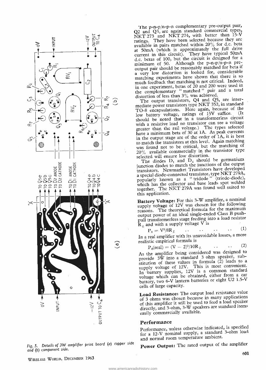
1-::::>
> 0....
0 ::z
t t • •
LJ..J LJ..J 0 0
LJ..JO LJ..JO o:r:: O:r:: 01- Ot-Z<t Z<t
G.!_() u <tu <tu ""' .r) th (\J (\J
00000 00 O · O 1-t-
> ~ "<!" N o....U - t-o I 6t-
t-t • •
Ql _() u '<t"<!-'<t occ 000 t-I-t-
The p-n-pjn-p-n complementary pre-output pair,
Q2 and Q3, are again standard commercial types,
NKT 273 and NKT 274, with better than 15-V
ratings. They have been selected because they are
available in pairs matched within 20% for d.c. beta
at SOmA (which is approximately the full drive
current in this circuit). They have typical SOmA
d.c. betas of 100, but the circuit is designed for a
minimum of 50. Although the p-n-p/n-p-n pre
output pair should be reasonably matched for beta if
a very low distortion is looked for, considerable
matching experiments have shown that there is so
much feedback that matching is not . critical. Indeed,
in one experiment, betas of 20 and 200 were used in
the complementary " matched " pair and a totaJ
distortion of less than 3% was achieved. The output transistors, Q4 and QS, are inter
mediate power transistors type NKT 352, in standard
T0-8 encapsulations. Here again, because of the
low battery voltage, ratings of 15V suffice. (It
should be noted that in a transformerless circuit
with a resistive load no transistor can see a voltage
greater than the rail voltage.) The types selected
have a minimum beta of 30 at 1A. As peak currents
in the output stage are of the order of 1A, it is best
to match the transistors at this level. Again matching
was found not to be critical, but the matching of
20% available commercially in the transistor type
selected will ensure low distortion. The diodes D 1 and D 2 should be germanium
junction diodes to match the junctions of the output
transistors. Newmarket Transistors have developed
a special diode-connected transistor, type NKT 279A,
popularly known as a " tridode " (triode-diode),
which has the collector and base leads spot welded
together. The NKT 279A was found well suited to
this application.
Battery Voltage: For this 3-W amplifier, a nominal
· supply voltage of 12V was chosen for the following
reasons. The theoretical formula for the maximum
output power of an ideal single-ended Class B push
pull transformerless stage feeding into a load resistor
R L and with a supply voltage V is
P 0 =V2/8RL (1)
In a real amplifier with its unavoidable losses, a more
realistic empirical formula is
P 0(real) = (V - 2)2 /1 OR L (2)
As the amplifier being considered was designed to
provide 3W into a standard 3 ohm speaker, sub
stitution of these values in formula (2) leads to a
supply voltage of 12V. This is most convenient.
In ·battery supplies, 12V is a common standard
voltage which can be obtained, either from a car
battery, two 6-V lantern batteries or eight U2 1.5-V
cells of large capacity.
Load Resistance: The output load resistance value
of 3 ohms was chosen because in many applications
of this amplifier it will be used to feed a load speaker
directly, and 3-ohm, 3-\Y/ speakers are standard item~
easily commercially available. )
Performance
Performance, unless otherwise indicated, is specified
for a 12-V nominal supply, a standard 3-ohm load
and normal room temperature ambient.
Fig. 5. Details of 3W amplifier print board (a) copper side and (b) component side. Power Output: The rated output of the amplifier
WIRELESS WoRLD, DECEMBER 1963 601
> ?,
-M
-•0
?©
0; U •-o •
in/ •
(O \ (•x, •) V# y
6?
LU UJ Q Q LU O LU O O 31 O -JZ
O 1— O |— z <i z <t Cf _D O 0 -< o lo in in rvj rvj o-oo-oo oo o o o o o o o
di -O u -4" Tj-
o-c?c? o o o
t Lt
\M9
Cr
fd
Fig. 5. Details of 3W amplifier print board (a) copper side and (b) component side.
Wireless World, December 1963
The p-n-p/n-p-n complementary pre-output pair, Q2 and Q3, are again standard commercial types, NKT 273 and NKT 274, with better than 15-V ratings. They have been selected because they are available in pairs matched within 20% for d.c. beta at 50mA (which is approximately the full drive current in this circuit). They have typical 50mA d.c. betas of 100, but the circuit is designed for a minimum of 50. Although the p-n-p/n-p-n pre- output pair should be reasonably matched for beta a very low distortion is looked for, considerable matching experiments have shown that there is so much feedback that matching is not critical. Indeed, in one experiment, betas of 20 and 200 were used in the complementary "matched" pair and a total distortion of less than 3% was achieved.
The output transistors, Q4 and Q5, are ^ter- mediate power transistors type NKT 352, in standard TO-8 encapsulations. Here again, because of the low battery voltage, ratings of 15V suffice. (It should be noted that in a transformerless circuit with a resistive load no transistor can see a voltage greater than the rail voltage.) The types selected have a minimum beta of 30 at 1A. As peak currents in the output stage are of the order of 1 A, it is best to match the transistors at this level. Again matching was found not to be critical, but the matching o 20% available commercially in the transistor type selected will ensure low distortion.
The diodes DI and D2 should be germanium junction diodes to match the junctions of the output transistors. Newmarket Transistors hav^ developed a special diode-connected transistor, type NK1 27yA, popularly known as a " tridode" (triode-diode), which has the collector and base leads spot welded together. The NKT 279A was found well suited to this application.
Battery Voltage: For this 3-W amplifier, a nominal supply voltage of 12V was chosen for the following reasons. The theoretical formula for the maximum output power of an ideal single-ended Class B push- pull transformerless stage feeding into a load resistor
and with a supply voltage V is
P0 = V2/8Rl . • • • • • • • C1)
In a real amplifier with its unavoidable losses, a more realistic empirical formula is
P0(real) = (V — 2)2/10R/j .. (2)
As the amplifier being considered was designed to provide 3W into a standard 3 ohm speaker, sub- stitution of these values in formula (2) leads to a supply voltage of 12V. This is most convenient In battery supplies, 12V is a common standard voltage which can be obtained, either from a car battery, two 6-V lantern batteries or eight U2 1.5-V cells of large capacity.
Load Resistance: The output load resistance value of 3 ohms was chosen because in many applications of this amplifier it will be used to feed a load speaker directly, and 3-ohm, 3-W speakers are standard items easily commercially available.
Performance
Performance, unless otherwise indicated, is specified for a 12-V nominal supply, a standard 3-ohm load and normal room temperature ambient.
6 Power Output: The rated output of the amplifier
www.americanradiohistory.com

is 3W r.m.s. (or 6W peak). However, the amplifier was found to perform satisfactorily over a ·voltage supply range of 9 to 15V, available output being, of course, greater at the higher voltage end and less at the lower.
If a deliberately poorly-stabilised power supply is used, which has a voltage of about 15V on no signal and falls to 12V on full output, then the music power rating, i.e., the instantaneous maximum power output available, will be over SW. However, a marginally bigger heat sink is necessary for this.
Efficiency: By selection of output transistors with very low base drive voltages and very high current gains, efficiencies of over 60% were obtained in practice. However, using standard production transistors, the output stage efficiency is more like 50%, i.e., at 3W output the current drain on the power supply at 12V is about tA.
Sensitivity: The amplifier has a typical 1 kc/s sensitivity of 50mV input for full 3W r.m.s. output. The input resistance (padded out with a series 680 0) is 1k 0. If a lower input resistance can be tolerated, then direct drive to the base of Ql (where the input resistance is about 3300) will give around 18mV sensitivity.
Frequency Response: The amplifier has a 3-db frequency response at 500m W from 50c/s-20kc/s without the feedback capacitor C1. With C1= lOOpF, the top end was cut to 12kc/s. This is more than adequate for commercial entertainment applications for which the circuit was primarily designed. It can easily be extended at the lower end by , increasing C2, C 3 and C 4, and ,at the upper end by reducing the feedback capacitance cf.
ALL HO LES 0·133" DIA.
' (DR !LL No 3~
I A ··+· I I ~ ' .-,- -. -+-
I -41 - --$-- --$- --$- 0·75 ' I . Qs ,
D~-~J 1-
1--t-:- 0·6 " ., 1·65" 0·187'' , I
I
r-0·9 75"--~, ~ ,, T~-02 ~~ 0·187 . .0·282 ' 1
I 0·75 " --$- - -fj7 - -$- -41- '
l ' a · ~ . , --$--I
4- -- -147f . --$- ' 0·141 I •
I
r 1·45
l '
~t:=-·~~~~~~-1 -·8-75_"===-3--0-,~~~------~~ 1
1[. jl ~
Fig. 6. Details of heat sink assembly of JW amplifier. , (a) Heat sink (b) Diode and transistor mounting.
602
A warning on high frequency tests is not out of place here. On the bench, it is a common experience to find output transistors run away on prolonged high-level, high-frequency testing.
In this connection, frequency response tests at a low-power level do not give a complete amplifier specification. A power response test is also desirable giving the permissible power outpur,across the same band as the specified low-level frequency response. On this basis, the 3-dB power response of the 3-W amplifier is 50c/s to lOkc/s only. In some ways this is academic, because in normal entertainment use, signals being amplified do not contain continuous high-level, high-frequency components. Also the impedance of the commonly-used moving-coil speaker rises rapidly at high frequencies and limits the output power possible. It is only when testing on an artificial non-inductive resistive load with a signal generator that trouble is usually experienced . .
Distortion: The total distortion of the 3-W amplifier was found to be typically 2% at 500m W output with a production spread of transistors. An interesting feature of these transformerless, complementarysymmetry circuits is that the total distortion does not rise steadily with output as happens in the case of transformer coupling. In general the distortion level remains fairly constant from a low signal level up to three-quarters of the rated output, then rises steadily This may be one explanation why transformerless complementary-symmetry amplifiers have such a reputation in the high fidelity field. On massive signal peaks the distortion does not rise significantly.
Lower distortion can be achieved with the basic circuit shown by reducing the values of R V 1 and R 2 proportionately. This increases the a.c. negative feedback, but of course lowers the gain.
Intermodulation distortion was not measured because no single accepted standard method · of measurement exists. However, the amplifier has been tested with an electronic organ where intermodulation distortion, if at all significant, shows itself up immediately because of the many frequencies at different power levels handled simultaneously. Its performance was found superior to a good valve amplifier.
Crossover distortion also is difficult to measure objectively. Total unweighted distortion measurements do not show it up adequately, and an amplifier with quite low measured total distortion may in fact have severe crossover distortion which is unacceptable on a listening test. One way commonly used to assess crossover distortion is to look at the output voltage waveshape on an oscilloscope and observe the discontinuity at the crossover point . This visual test is deceptive because sometimes crossover distortion that looks bad on the oscilloscope does not give rise to bad reproduction. The only certain way to deal with this satisfactorily is by listening tests on simple sine waves.
If the crossover distortion level attained with the circuit given is unacceptable for the . requirements of the designer, it can be impJ;oved in two ways. The first is to increase the standing current in the output transistors to a higher level than the 5mA specified in the circuit. It will be found that with these intermediate power transistors, " visual " crossover disappears by the time the bias current reaches 10 or 12mA. The trouble with this method is
(Continued on page 603)
WIRELESS \VJORLD, DECEMBER 1963
is 3W r.m.s. (or 6W peak). However, the amplifier was found to perform satisfactorily over a voltage supply range of 9 to 15V, available output being, of course, greater at the higher voltage end and less at the lower.
If a deliberately poorly-stabilised power supply is used, which has a voltage of about 15V on no signal and falls to 12V on full output, then the music power rating, i.e., the instantaneous maximum power output available, will be over 5W. However, a marginally bigger heat sink is necessary for this.
Efficiency: By selection of output transistors with very low base drive voltages and very high current gains, efficiencies of over 60% were obtained in practice. However, using standard production transistors, the output stage efficiency is more like 50%, i.e., at 3W output the current drain on the power supply at 12V is about JA.
Sensitivity: The amplifier has a typical 1 kc/s sensitivity of 50mV input for full 3W r.m.s. output. The input resistance (padded out with a series 680 Q) is IkQ. If a lower input resistance can be tolerated, then direct drive to the base of Q1 (where the input resistance is about 330 Q) will give around 18mV sensitivity.
Frequency Response: The amplifier has a 3-db frequency response at 500mW from 50c/s-20kc/s without the feedback capacitor Cf. With C/= lOOpF, the top end was cut to 12kc/s. This is more than adequate for commercial entertainment applications for which the circuit was primarily designed. It can easily be extended at the lower end by increasing C2, C3 and C4, and at the upper end by reducing the feedback capacitance Cf.
ALL HOLES 0-l33"DIA. (DRILL No 33)
-0- --0-- -0- T Q5 ■
7r% 4 0'187 1. D|-0-y 175
T0-D2
! tei? -0~ "0-,-^
Q4-0--'-
!0'282' ! 1 h-. -A. --fh-JL
PLASTIC BUSH ■ ON
MOUNTING CLIP
J I INSULATING y MICA WASHER BETWEEN TRANSISTOR AND HEAT SINK.
Fig. 6. Details of heat sink assembly of 3W amplifier, (a) Heat sink (b) Diode and transistor mounting.
A warning on high frequency tests is not out of place here. On the bench, it is a common experience to find output transistors run away on prolonged high-level, high-frequency testing.
In this connection, frequency response tests at a low-power level do not give a complete amplifier specification. A power response test is also desirable giving the permissible power output^across the same band as the specified low-level frequency response. On this basis, the 3-dB power response of the 3-W amplifier is 50c/s to lOkc/s only. In some ways this is academic, because in normal entertainment use, signals being amplified do not contain continuous high-level, high-frequency components. Also the impedance of the commonly-used moving-coil speaker rises rapidly at high frequencies and limits the output power possible. It is only when testing on an artificial non-inductive resistive load with a signal generator that trouble is usually experienced.
Distortion: The total distortion of the 3-W amplifier was found to be typically 2% at 500mW output with a production spread of transistors. An interesting feature of these transformerless, complementary- symmetry circuits is that the total distortion does not rise steadily with output as happens in the case of transformer coupling. In general the distortion level remains fairly constant from a low signal level up to three-quarters of the rated output, then rises steadily This may be one explanation why transformerless complementary-symmetry amplifiers have such a reputation in the high fidelity field. On massive signal peaks the distortion does not rise significantly.
Lower distortion can be achieved with the basic circuit shown by reducing the values of RVi and R2
proportionately. This increases the a.c. negative feedback, but of course lowers the gain.
Intermodulation distortion was not measured because no single accepted standard method of measurement exists. However, the amplifier has been tested with an electronic organ where inter- modulation distortion, if at all significant, shows itself up immediately because of the many frequencies at different power levels handled simultaneously. Its performance was found superior to a good valve amplifier.
Crossover distortion also is difficult to measure objectively. Total unweighted distortion measure- ments do not show it up adequately, and an amplifier with quite low measured total distortion may in fact have severe crossover distortion which is un- acceptable on a listening test. One way commonly used to assess crossover distortion is to look at the output voltage waveshape on an oscilloscope and observe the discontinuity at the crossover point. This visual test is deceptive because sometimes crossover distortion that looks bad on the oscillo- scope does not give rise to bad reproduction. The only certain way to deal with this satisfactorily is by listening tests on simple sine waves.
If the crossover distortion level attained with the circuit given is unacceptable for the requirements of the designer, it can be improved in two ways. The first is to increase the standing current in the output transistors to a higher level than the 5mA specified in the circuit. It will be found that with these intermediate power transistors, " visual " crossover disappears by the time the bias current reaches 10 or 12mA. The trouble with this method is
(Continued on page 603)
602 Wireless World, December 1963
www.americanradiohistory.com

DECEMBER, 1963 WIRELESS W ORLD
1 2 or 4
+17 Y AMPLI FI ER Bandwidth-D.C. to 10 kc/s Sensitivity-
75
A Beam Switch giving 1, 2 or 4 traces, each with indep
endent Y gain and shift controls, and a 17" rectangular
cathode ray tube-these are just two of the advantages
offered by the Airmec Display Oscilloscope Type 279.
Although designed primarily for demonstration and in
structional use in Schools, Technical Colleges and Uni
versities, the exceptionally large viewing screen (9"x 13")
and a very bright orange trace visible at 50 feet make this
Oscilloscope extremely Sl:litable for many other uses, in
cluding analogue computers , medical applications and
wobbulators.
Greater than 10 ems per volt Beams-1, 2 or 4 with independent gain and shift controls
The Display Oscilloscope Type 279, together with the 4
channel Oscilloscope Type 249 and High Speed model
Type 294, forms part of the comprehensive range of high
quality electron ic instruments which A irmec produce
for use in laboratories and workshops.
X AMPLIFIER Bandwidth-D.C. to 8 kc/s Sensitivity-Greater than 8 ems per volt
TI ME BASE 317 Sweep Time- · 1 millisecond to 1 second Beam Switching-Sequential
TIM E BAS E 318 Sweep Time-0.5 second to 30 second Beam Switching-Incremental Triggered operation
Ai rrn ec for peak performance cons istent ly
LABORATORY INSTRUMENTS DIVISION
Oscilloscopes, Wave Analysers, Signal Generators, Phase Meters, Valve Voltmeters,
Ohmmeters, High Speed Counters, etc.
AIRMEC LIMITED, HIGH WYCOMBE, BUCKS ., ENGLAND.
TELEPHONE : HIGH WYCOMBE 2501 (10 LINES)
3WW - 113 FOR FURTHER DETA I LS. A.P272
D
December, 1963 Wireless World 75
or
4
1
a
fi ■
+17
A Beam Switch giving 1, 2 or 4 traces, each with indep- endent Y gain and shift controls, and a 17" rectangular cathode ray tube—these are just two of the advantages offered by the Atrmec Display Oscilloscope Type 279. Although designed primarily for demonstration and in- structional use in Schools, Technical Colleges and Uni - versities, the exceptionally large viewing screen (Q'^IS") and a very bright orange trace visible at 50 feet make this Oscilloscope extremely suitable for many other uses, in- cluding analogue computers, medical applications and wobbulators. The Display Oscilloscope Type 279, together with the 4 channel Oscilloscope Type 249 and High Speed model Type 294, forms part of the comprehensive range of high quality electronic instruments which Airmec produce for use in laboratories and workshops.
Z** * * i m
0 * IP ^
W ^ > m <
Y AMPLir ER Bandwidth—D.C. to 10 kc/s Sensitivity- Greater than 10 cms per volt Beams—t, 2 or 4 with independent gain and shift controls
X AMPLIFIER Bandwidth—D.C. to 8 kc/s Sensitivity- Greater than 8 cms per volt
TIME BASE 317 Sweep Time— 1 millisecond to 1 second Beam Switching—Sequential
TIME i \SE 318 Sweep Tine— 0.5 second to 30 second Beam Switch! g— Incremental Triggered operation
AP272
D
Airmec for peak performance consistently
LABORATORY INSTRUMENTS DIVISION Oscilloscopes, Wave Analysers, Signal Generators, Phase Meters, Valve Voltmeters, Ohmmeters, High Speed Counters, etc.
AIRMEC LIMITED, HIGH WYCOMBE, BUCKS., ENGLAND. TELEPHONE: HIGH WYCOMBE 2501 (10 LINES)
3WW—113 FOR FURTHER DETAILS.
www.americanradiohistory.com

76 VVIRELESS VVORLD DECEMBER, 1963
turnover
t
I turn over from LP/S to 78. I'm ACOStereo 81 ceramic, one of the famous family of ... Acos mono and stereo cartridges, and proud of it. VVe turn in a first-rate performance
;Jt in very many of the best and best-known record players in this country and overseas. If you manufacture record players and you do not already use us extensively, consider turning over to us-we keep your costs down, your quality up. If you use a record
I i player, fit one of us as replacement and turn over a new leaf in better sound. Your Dealer
, f will tell you which one is right for your equipment
;! 0 ~ e e ~ . are doing things in styli ~------L-------~------~
Acos GPG"l
ACu~~reo AGO~~ereo Cosmocord Ltd., Eleanor "Cross Road, Waltham Cross, Herts . Telephone: WS 27331
3WW - 114 FOR FURTHER DETAILS,
Wireless World December, 1963
turn over
/•
i
<c
c
i i i
i vf
IT
I f |
V:. I turn over from LP/S to 78. I'm ACOStereo 81 ceramic, one oi :he famous iri [y of Acos mono and stereo cartridges, and proud of it. We turn a first-rate d« formance in very many of the best and best-known record players in this country a i overseas. If you manufacture record players and you do not already use us i pensively, consider turning over to us—we keep your costs down, your quality up. If yc i e a record player, fit one of us as replac uent and turn over a new leaf in better sound. Your Dealer will tell you which one is right for your equipment.
are doing things in styli
3WW-1T4 FOR FURTHER DETAILS.
www.americanradiohistory.com

---~r-----.------...-----./'1\~-----c-lzV Damping Factor~
0·05J1
CRYSTAL PICK-UP INPUT
;c,;oop 2·2k
470
Z.Zk The output resistance of this amplifier (in effect that of an emitter-follower with no series emitter resistor)
lk OUTPUT is low (0.2-0.Sohm ~--1wv'VV---~ depending on trans
0·05)1
'-----' '--~I Ok
0·5).1
istor betas). Damping factors of about 10 are typical. The circuit was tested with a
. standard 3-ohm noninductive resistor but additional tests were run with a 0.2mH inductor in series with the resistor to simulate a real speaker. This technique -is particularly important in
o---.....---+------4--4-~;;....---4---4~--+-----.r-----4---<J o v evaluating the high fre-quency performance of
Fig. 7. Circuit of pre-amplifier suitable for 3W amplifier. the amplifiers. -
that the standing dissipation in the output transistors rises with the bias current level and if the equipment is to operate over the same ambient temperature range a bigger heat sink has to be used. For lOrnA quiescent current a suggested heat sink size would be 3 x 3 x f-6 in. blackened aluminium.
The second method of reducing crossover distortion is to leave the quiescent output bias current at 5mA as designed, and increase the a.c. feedback from output to driver base by reducing RV1 and R 2•
This increases the overall a.c. feedback and reduces the effect of crossover distortion on performance.
In general, the problem resolves itself into a balance of output transistor dissipation, standing bias current, gain and distortion. The optimum can only depend on the individual designer's requirement.
A simple bench test for total distortion that can be applied without setting up elaborate test equipment is to connect a d.c. voltmeter across the output from the emitter of Q4 to earth. With this, the d.c. level is first verified as being half the rail voltage under no-signal conditions. Then the input signal is turned up, and if the distortion level is lowj the d.c. reading will not change substantially. If it does change, the presence of distortion is indicated. After a little experience it is possible to tell which transistor is contributing the major part of the distortion by the direction in which the direct voltage moves.
Noise and Hum: Noise is relatively unimportant in this amplifier because the transistor selected for the first position has a typical noise factor of lOdB and the noise introduced by this stage is small compared with noise introduced by any pre-amplifier used.
Hum again is not critical because of the low circuit impedances and lack of transformers in the design.
Supply Currents: Current dr.ain on the power supply is · typically as follows:-Power
Ambient Temperature Range: The circuit is designed to operate satisfactorily from ooc to 45°C, ie., the range of ambient temperature for which consumer products are normally rated. The temperature compensation diodes D 1 and D 2 satisfactorily prevent crossover distortion rising appreciably at the low-temperature end, and prevent the output bias .-currents rising excessively at the high temperature end.
Mechanical Aspects Dimensions: The prototype 3-W amplifier illustrated in Fig. 4 is approximately 5 xI! x l!in and in its finished form weighs only 2 oz. Holes are provided on the end of the heat sink for mounting the unit. It has only four end connections-input, output, +OV, -12V. _ The end connections are spaced so that they fit into a standard end-connector socket but, as the peak currents handled are well over IA, it has been found in practice that many sockets introduce sufficient contact resistance to lead to distortion. It is best to solder terminal connections to the board.
Component Layout: Fig. 5(a) gives a diagrammatic drawing of the copper side of the printed
DI,DZ,D3&D4 = NKT 349030
ISOfl zW
12V zA
r.m.s.
24oV A.C.
output: OmW lOOmW 500mW lW 2W 3W + z,ooo,u F. zsV Battery Current: 7.5mA lOOmA 200mA 275mA 375mA 500mA . Fig. 8. Circuit of mains power pacl< for 3W amplifier.
WIRELESS WORLD, DECEMBER 1963 603
OUTPUT
i I1" 5,^ )T
CRYSTAL PICK-UP
INPUT lk< ^ <470 > muT >
Fig. 7. Circuit of pre-amplifier suitable for 3W amplifier.
-12V Damping Factor : The output resistance of this amplifier (in effect that of an emit- ter-follower with no series emitter resistor)
>UT is low (0.2—0.5ohm depending on trans- istor betas). Damping factors of about 10 are typical. The circuit was tested with a standard 3-ohm non- inductive resistor but additional tests were run with a 0.2mH inductor in series with the resistor to simulate a real speaker. This technique is particu- larly important in
3 V evaluating the high fre- quency performance of the amplifiers.
that the standing dissipation in the output transistors rises with the bias current level and if the equipment is to operate over the same ambient temperature range a bigger heat sink has to be used. For 10mA quiescent current a suggested heat sink size would be 3 x 3 x xffi11- blackened aluminium.
The second method of reducing crossover distor- tion is to leave the quiescent output bias current at 5mA as designed, and increase the a.c. feedback from output to driver base by reducing RVj and R;,. This increases the overall a.c. feedback and reduces the effect of crossover distortion on performance.
In general, the problem resolves itself into a balance of output transistor dissipation, standing bias cur- rent, gain and distortion. The optimum can only depend on the individual designer's requirement.
A simple bench test for total distortion that can be applied without setting up elaborate test equip- ment is to connect a d.c. voltmeter across the output from the emitter of Q4 to earth. With this, the d.c. level is first verified as being half the rail voltage under no-signal conditions. Then the input signal is turned up, and if the distortion level is low; the d.c. reading will not change substantially. If it does change, the presence of distortion is indicated. After a little experience it is possible to tell which transistor is contributing the major part of the dis- tortion by the direction in which the direct voltage moves.
Noise and Hum: Noise is relatively unimportant in this amplifier because the transistor selected for the first position has a typical noise factor of lOdB and the noise introduced by this stage is small compared with noise introduced by any pre-amplifier used.
Hum again is not critical because of the low circuit impedances and lack of transformers in the design.
Supply Currents: Current drain on the power supply is typically as follows:— Power output: OmW lOOmW 500mW 1W 2W 3W Battery Current: 7.5mA 100mA 200mA 275mA 375mA 500mA
Ambient Tempera- ture Range: The circuit is designed to operate satisfactorily from 0oC to 450C, i.e., the range of ambient temperature for which consumer products are normally rated. The temperature compensation diodes D1 and Dg satisfactorily prevent crossover distortion rising appreciably at the low-temperature end, and prevent the output bias currents rising excessively at the high temperature end.
Mechanical Aspects
Dimensions: The prototype 3-W amplifier illus- trated in Fig. 4 is approximately 5 X If X 1 fin and in its finished form weighs only 2 oz. Holes are provided on the end of the heat sink for mounting the unit. It has only four end connections—input, output, -f 0V, —12V. The end connections are spaced so that they fit into a standard end-connector socket but, as the peak currents handled are well over 1A, it has been found in practice that many sockets introduce sufficient contact resistance to lead to distortion. It is best to solder terminal connections to the board.
Component Layout: Fig. 5(a) gives a diagram- matic drawing of the copper side of the printed
Di.Dz ,D3 & Da MKT 349D30
a Di Dz
i D3 D4-
Z,000uF
2,000/UF, 25V
Fig. 8. Circuit of mains power pack for 3W amplifier.
Wireless World, December 1963 603
www.americanradiohistory.com
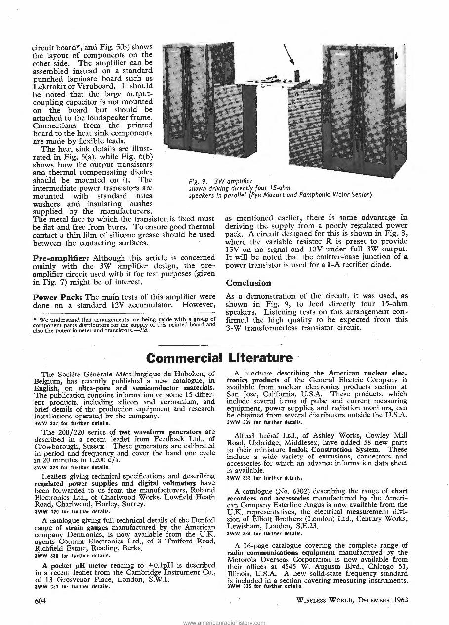
circuit board*, and Fig. S(b) shows the layout of components on the other side. The amplifier can be assembled instead on a standard punched laminate board such as Lektrokit or Veroboard. It should be noted that the large outputcoupling capacitor is not mounted on the board but should be attached to the loudspeaker frame. Connections from the printed board to the heat sink components are made by flexible leads.
The heat sink details are illustrated in Fig. 6(a), while Fig. 6(b) shows how the output transistors and thermal compensating diodes should be mounted on it. The intermediate power transistors are mounted with standard mica washers and insulating bushes supplied by the manufacturers .
Fig. 9. 3W amplifier shown driving directly four 15-ohm speakers in parallel (Pye Mozart and Pamphonic Victor Senior)
The metal face to which the transistor is fixed must be flat and free from burrs. To ensure good thermal contact a thin film of silicone grease should be used between the contacting surfaces.
Pre-amplifier: Although this article is concerned mainly with the 3W amplifier design, the preamplifier circuit used with it for test purposes (given in Fig. 7) might be of interest.
Power Pack: The main tests of this amplifier were done on a standard 12V accumulator. However,
* We understand that arrangements are being made with a group of component parts distributors for the supply of this printed board and also the potentiometer and transistors .-Ed.
as mentioned earlier, there is some advantage in deriving the supply from a poorly regulated power pack. A circuit designed for this is shown in Fig. 8, where the variable resistor R is preset to provide 15V on no signal and 12V under full .3W output. It will be noted that the emitter-base junction of a power transistor is used for a 1-A rectifier diode.
Conclusion
As a demonstration of the circuit, it was used, as shown in Fig. 9, to feed directly four 15-ohm speakers. Listening tests on this arrangement confirmed the high quality to be expected from this 3-W transformerless transistor circuit.
Commercial Literature The Societe Generale Metallurgique de ·Hoboken, of
Belgium, has recently published a new catalogue, in English, on ultra-pure and semic.onductor materials. The publication contains information on some 15 different products, including silicon and germanium, and brief details of the production equipment and research installations operated by the company. 3WW 327 for further details.
The 200/220 series of test waveform generators are described in a recent leaflet from Feedback Ltd., of Crowborough, Sussex. These generators are calibrated in period and frequency and cover the band one cycle in 20 minutes to 1,200 c/s. · 3WW 328 for further details .
Leaflets giving technical specifications and describing regulated power supplies and digital voltmeters have been forwarded to us from the manufacturers, Roband Electronics Ltd., of Charlwood Works, Lowfield Heath Road, Charlwood, Horley, Surrey. 3WW 329 for further details.
A catalogue giving full technical details of the Denfoil range of strain gauges manufactured by the American company Dentronics, is now available from the U.K. agents Coutant Electronics Ltd., of 3 Trafford Road, ~ichfield Estate, Reading, Berks. · 3WW 330 for further details.
A pocket pH meter reading to ±O.lpH is described in a recent leaflet from the Cambridge Instrument Co., of 13 Grosvenor Place, London, S.W.l. JWW 331 for further details .
604
A brochure describing the American nuclear electronic.s products of the General Electric Company is available from nuclear electronics products section at San Jose, California, U.S.A. These products, which include several items of pulse and current measuring equipment, power supplies and radiation monitors, can be obt!lined from several distributors outside the U.S.A. 3WW 332 for further details.
Alfred Imhof Ltd., of Ashley Works, Cowley Mill Road, Uxbridge, Middlesex, have added 58 new parts to their miniature Imlok Construction System. These include a wide variety of extrusions, connectors_and accessories for which an advance information data sheet is available. · 3WW 333 for further details.
A catalogue (No. 6302) describing the range of chart recorders and accessories manufactured by the American Company Esterline Angus is now available from the U.K. representatives, the electrical measurement division of Elliott Brothers (London) Ltd., Century Works, Lewisham, London, S.E.23. JWW 334 for further details.
A 16-page catalogue covering the complet.! range of radio communications equipment manufactured by the Motorola Overseas Corporation is now available from their offices at 4545 W. Augusta · Blvd., Chicago 51, Illinois, U.S.A. A new solid-state frequency standard is included in a section covering measuring instruments. 3WW 335 for further details.
WIRELESS WORLD, DECEMBER 1963
circuit board*, and Fig. 5(b) shows the layout of components on the . «l ■ if p other side. The amplifier can be assembled instead on a standard |^| Jil pimched laminate board such as | | in Lektrokit or Veroboard. It should | IB ||r be noted that the large output- coupling capacitor not mounted I - |w U ^ on the board but should be 1 , ffil fg attached to the loudspeaker frame. Connections from the printed board to the heat sink components are made by flexible leads. Hj
The heat sink details are i iiust- rated in Fig. 6(a), while Fig. 6(b) shows how the output transistors and thermal compensat ig diodes should be mounted on it. The f/g. 9. 3 intermediate power trans otors are shown dri\ mounted with standard mica speakers i washers and insulating bushes supplied by the manufacturers. The metal face to which the transistor Is fixed must be flat and free from burrs. To ensure good thermal contact a thin film of silicone grease should be used between the contacting surfaces..
Pre-amplifier; Although this article is concerned mainly with the 3W amplifier design, the pre- amplifier circuit used with it for test purposes (given in Fig. 7) might be of interest.
Power Pack; The main tests of this amplifier were done on a standard 12V accumulator. However,
" We understand tha arrangements are being made with gro p of component parts distributors for the supply of this printed board and also the potentiometer and transistors.—Ed.
iS - -
Fig. 9. 3W amplifier shown driving directly four 15-ohm speakers in p irallel (Pye Mozart and Pamphonic Victor Senior)
as mentioned earlier, there is some advantage in deriving the supply from a poorly regulated power pack. A circuit designed for th is shown 1 Fig. 8, where the variable resistor R is preset to provide 15V on no signal and 12V under full 3W output. It will be noted that the emitter-base junction of a power transistor is used for a 1-A rectifier diode.
Conclusion
As a demonstration of the circuit, i. was used, as shown in Fig. 9, to feed directly four 15-ohm speakers. Listening tests on this arrangement con- firmed the high quality to be expected from th-s 3-W transformerless transistor circuit.
Commercial Literature
The Societe Generale Metallurgique de Hoboken, cf Belgium, has recently pub shed a new catalogue, in English, on ultra-pure and semiconductor materials. The publication contains information on some 15 ditier- ent products, including si] :on and germanium, and brief details of the production equipment and research installations operated by the company. 3WW 327 for further details.
The 200/220 series of test waveform generators are described in a recent leaflet from Feedback Ltd., of Crowborough, Sussex. These generators are calibrated in period and frequency and cover the band one cycle in 20 minutes to 1,200 c/s. 3WW 328 for furthor details.
Leaflets giving technical specifications and descr ing regulated power supplies and digital voltmeters have been forwarded to us from the manufacturers, Roband Electronics Ltd., of Charlwood Works, Lowfield Heath Road, Charlwood, Horley, Surrey. 3WW 329 for further details.
A catalogue giving full techn- -al details of the Derioil range of strain gauges manufactured by the American company Dentronics, is now available from the U.K. agents Coutant Electror :s Ltd., of 3 Trafford Road, I "chfield Estate, Reading, Berks. 3WW 330 for further details.
A pocket pH meter reading to ±0.1pH is described in a recent leaflet from the Cambridge Instrument Co., of 13 Grosvenor Place, London, S.W.I. 3WW 331 for further details.
A brochure describing the American nuclear elec- tronics products of the General Electric Company is available from nuclear electron! s products section at San Jose, California, U.S.A. These products, which include several items of pulse and current measuring equipment, power supplies and rad on mon ors. can be obtained from several distributors outside the U.S.A, 3WW 332 for (urther details.
Alfred Imhof Ltd., of Ashley Works, Cowley Mill Road, Uxbridge, Middlesex, have added 58 new parts to their miniature Imlok Construction System. These include a wide variety of extrusions, connectors^and accessories for which an advance informal-on data sheet is ava able. 3WW 333 for further details.
A catalogue (No. 6302) describing the range of chart recorders and accessories manufactured by the Ameri- can Company Esterline Angus is now available from the U.K. representatives, the electrical measurement divi- sion of Elliott Brothers (London) Ltd., Century Works, Lewisham, London, S.E.23. 3WW 334 for further details.
A 16-page catalogue covering the complete range of radio communications equipment manufactured by the Motorola Overseas Corporation is now ava ible from their offices at 4545 W. Augusta Blvd., Chicago 51, Illinois, U.S.A. A new solid-state frequency standard is included in a section covering measuring instruments. 3WW 335 for further details.
604 \ Wireless World, December 1963
www.americanradiohistory.com

WOBLD OF WIRELESS
Research Study SINCE a significant proportion of research and development effort of the electronics industry is employed on defence contracts, an examination is to be made to determine if any of this work could be applied to products for the .civil market. A team of economists, scientists and engineers are, therefore, to undertake a study within sections of the electronics industry with a view to applying t'his work to other industries, especially in the field of automation. Similarly, the team are to consider work being done . in the fields of line and radio telecommunications, but will not cover consumer products such as domestic ,radio, television, sound reproduction equipment, etc.
Arrangements for the study are being made by the Department .of Scientific and Industrial Research in conjunction with ·seven trade associations.* The branches of the Ministry of Aviation, Board of Trade, Admiralty and Post Office conce,rned with electronics have already agreed !o take part in the study and a number of electronics firms are being approached by the trade associations to participate.
There will be full consultation between the Government departments concerned and the trade associations at all stages of the study and particularly in considering any conclusions that may be reached. It is hoped that the study will be completed in eighteen months to two years.
*British Electrical and Allied Manufacturers' Association Business Equipment Trades Association Electronic Engineering Associaton · Electronic Valve and Semi~Conductor Manufacturers' Association Radio and Electronic Component Manufacturers' Federation Scientific Instrument Manufacturers' Association Telecommunication Engineering & Manufacturing Association
Receiving B.B. C.2 THE channels provisionally assigned for B.B.C.2 at the U.K.'s first 18 u.h.f. :s1ations., are given in the booklet "How to Receiv:e B.B.C.Z" which the Corporation's Engineering Information Department has prepared. Initially it will b.e distributed through dealers in the service area of the London transmitter but copies are also obtainable direct from the E.I.D. at Broadcasting House for which requests should be sent on a _postca-r.d.
After outlining the differences between the present v.h.f. service and the new one, the booklet gives ·some general guidance on the type of aerial requ1r.ed in particular situations.
The Crystal Palace transmitter (channel 33) is scheduled to come into service on the 20th :April and the following eight stations (with their proposed _B.B:C.2 channels in parentibeses), are expected to be opened in 1'965 :-Sutton Coklfield ( 40), Black Hill (46), Wenvoe (44), Wiinter Hill '(6zy, Emley Moor '(51), Divis (27), Rowridge (undecided)~ Pontop Pike (64).
U.H.F. Test Transtnissions THE 625-if1ne field trials fwm the B.B.C. transmitter at Crystal Palace on channel 33 ended on 15th November. F:rom about the midd1e of December there ··.vill be intermittent test transmissions until the end of the year but as some of these will be on very reduced power they will not generally be suitable for reception tests.
Details of the regular test transmissions starting early in 1964 in preparation for the opening ·of B.B.C.2 in April will be announced later.
WIRELESS WORLD, DECEMBER 1963
Electronics in H.N. C. FOLLOWING the introduction of the Ordinary National Certificate in Engineering and the consequent elimination by 1965 of the Ordinary National Certificate in Electrical Engineering, the Minister of Education has had under consideration the position of the existing H.N.C. and Diplomas in Electrical Engineering. After consultation with the I.E.E. and the Brit.I.R.E. it has been agreed that the title of these certificates and diplomas should be widened to include electronic engineering. A new joint committee is to be set up to draft new rules for Higher National Certificates and Diplomas in Electrical and Electr-onic Engineering. As from September, 1965, it is envisaged that H.N.C. and Diploma courses should operate under the new rules.
Relay Services AT the annual luncheon of the Relay Services Association, whose members supply relayed television to some 750;000 (about one in 15 of the country's licence holders), the chairman, Geoffrey Parker, of Macclesfield, spoke of the prospects of relaying B.B.C.Z. This could extend considerably the coverage of the London station well beyond its normal limits although, of course, relay organizations under · the terms of their licence, must receive the signal over the air. It has been suggested that relay organizations should be permitted to convert the . signal for display on 405-line receivers, but this would negate the decision to change the country's television standard. . Relaying will certainly improve the signal-to-noise ratio for viewers in fringe areas and, as the signal is frequency converted to v.h.f., viewers wiU not need receivers with a u.h.f. ".front end.'' ·
Portable ground station capable of providing 12 two-way voice channels with communications satellites. The station, which is completely self-contained and am handle facsimile, multichannel teleprinter circuits and high-speed dota _transmissions, .has -been supplied to the German .Bundespost by the International Telephone and Telegraph Corporation.
605
WORLD or WIRELESS
Research Study
SINCE a significant proportion of research and develop- ment effort of the electronics industry is mployed on defence contracts, an examination is to be made to determine if any of th ; work could be applied to pro- ducts for the civil market. A team of economists, scientists and engineers are, therefore, to undertake a study within sections of the electronics industry with a view to applying this votk to other ndustries, especially in the field of automation. Similarly, the team are to consider work being done in the fields of line and radio telecommunications, but will not cover consumer pro- ducts such as domestic radio, television, sound reproduc- tion equipment, etc.
Arrangements for the study are being made b he Department of Scientific and Industrial Research in conjunction v th seven trade associations. T e branches of the Ministry of Aviation, Board of Trade, Admiralty and Post Office concerned with ectronics have already agreed to take part i the study and a number of electronics firms are being approached by the trade associations to parti pate.
There will be full consultation between the Govern- ment departments concerned and the trade associations at all stages of he study and particularly in considering any conclusions that may be reached. It is hoped that the study will be completed in eighteen months to two years.
♦British Electrical and Allied Manufacturers' Association Business Eqinpment Trades Association Electronic engineering Associati. . Electronic Valve and Semi-Canductor Manufacturers' Association Radio and Electronic Component Manufacturers' Federation Scientific Instrument Manufacturers' Association Telecommunication Engineering & Manufacturing Association
Electronics in H.N.C.
FOLLOWING the introduction of the Ordinary National Certificate in Engineering and the consequent elimins on by 1965 of the Ordinary National Certificate in Electrical Engineering, 'he Minister of Education has had under considerat n the position of the existing H.N.C. and D jlomas in Electrical Engineering. After consultation w h the LI E. and the Brit.LR.E. it has been agreed that the title of these certificates and diplomas should be widened to include electronic engin- eering. A new joint committee is to be set up to draft new rules for Higher National Certificates and Diplomas in Electrical and Electronic Engineering. As from September, 1965, it is envisaged that H.N.C. and Diploma courses should operate under the new rules.
Relay Services
AT the annual luncheon of the Relay Services Asso- ciation, whose members supply relayed televis an to some 750,000 (about one in 15 of the country's licence holders), the chairman, Geoffrey Parker, of Macclesfieil, spoke of the prospects of relaying B.B.C.2. This could extend considerably he overage of the London station well beyond its normal limits although, of course, relay organizations under the terms of their licence, must receive the signal over the air. It has been suggested that relay organizations should be permitted to convert the signal for display cm 405-line receivers, but this would negate the decision to change he country's tele- vision standard. Relaying will certainly improve the signal-to-noist ratio for viewers in fringe areas and, as the signal is frequency converted to v.h.f., viewers will not need receivers with a uh.f. "front end."'
Receiving B.B.C.2
THE channels provisionally assigned for B.B.C.2 at the UJC.'s first 18 u.h.f. stations, are given in the book1 t "How to Receive B.B.C.2" vhich the Corporation's Engineering Infe rmation Department has prepared. Initially i will be disl touted through dealers n the service area of the London transmitter but copies are also obtainable direct from the E.I.D. at Broadcasting House for which requests should be sent on a postcard.
After outlining the differences between the present vJi.f. service and the new one, the booklet gives some general guidance on the type of aerial required in particular .situations.
The Crystal Palace transmitter (channel 33) is scheduled to come into ser "re on the 20th April and the following eight stations (with theii proposed B.B.C.2 channels in parentheses), are expected to be opened in 1965;—Sutton Cokffieid (40), Black Hill (46), Wenvoc (44), Winter Hill (62), Emley Moor <51), Div (27), Rowridge (undecided), Pontop Pike (64).
U.H.F. Test Transmissions
THE 625-line field trials from the B.B.C. transmitter at Crystal Palace on channel 33 ended on 15th Novem- ber. From about the middle of December there will be intermittent test transmissions un 1 the end of the year but as some of these will be on very reduc il power they will not generally be suitable 'or reception tests.
L trails of the regular test transmissions starting early in 1964 in preparation for the opening of B.B.C.2 in April will be announced later.
Hi Si
Portable ground station capable of providing 12 two-way voice channels with communications satellites. The station, which is completely self-contained and can handle facsimile, multi- channel teleprinter circuits and high-speed data transmissions, has been supplied to the German Bundespost by the Inter- national Telephone and Telegraph Corporation.
Wireless World, December 1963 605
www.americanradiohistory.com
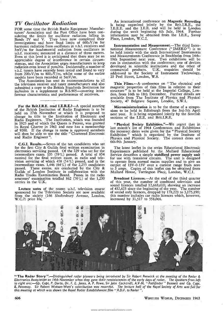
TV Oscillator Radiation FOR some time the British Radio Equipment Manufacturers' Association and the Post Office have been considering the limits for oscillator radiation falling in Bands IV and V. They have now completed their investigations and have fixed limits of 600,u.V /m for harmonic radiation from oscillators in v.h.f. receivers and 3mV /m for fundamental radiation from oscillators in u.h.f. receivers; measured at a distance of three metres. Even at this level it is anticipated that there may be an appreciable degree of interference in certain circumstances, and the Association urges manufacturers to keep radiation even lower if possible. Incidentally, a number of v.h.f. tuners have recently been tested and found to vary from 200,u.V /m to 800,u.V jm, whilst some of the earlier models have been recorded at 5mV /m.
The Association has sent its recommendations to all the television receiver and tuner manufacturers and a,lso submitted a copy to the British Standards Institution for inclusion in a supplement to B.S.905-covering interference characteristics and performance of receivers.
For the Brit.I.R.E. read I.E.R.E.?-A special meeting of the British Institution of Radio Engineers is to be held on 27th November at which it is proposed to change its title to the Institution of Electronic and Radio Engineers. The Institution, which was founded in 1925 and of which the Queen is Patron, was granted its Royal Charter in 1961 and now has a membership of 9200. If the change in name is approved members will then be able to use the title " Chartered Electronic and Radio Engineer ".
C.G.I. Results.-Seven of the ten candidates who sat for the first City & Guilds final written examination in electronics servicing passed. Of the 229 who sat for the intermediate exam. 135 (59%) passed. A total of 854 entered for the final written exam. in radio and television servicing of which 458 (54%) passed, and in the intermediate exam. 1,446 (64%) of the 2,255 candidates passed. These exams. are conducted by the City & Guilds of London Institute in collaboration with the Radio Trades Examination Board. Passes in the radio amateurs' examination totalled 862 (70%) of the 1,230 entries in the U.K.
Lecture notes of the recent u.h.f. television course sponsored by the Television Society are now available from the society (166 Shaftesbury Avenue, London, W.C.2) price lOs. -
An international conference on Magnetic Recording is being organized jointly by the Brit.I.R.E., the I.E.E.E. and the I.E.E. and will be held in London during the week beginning 6th July, 1964. Further information may be obtained from the I.E.E., Savoy Place, London, W.C.2.
Instrumentation and Measurement.-The third International Measurement Conference (" IMEKO ") is to be held jointly with the sixth International Instruments and Measurements Conference in Stockholm from 14th-19th September next year. Two exhibitions will be run in conjunction with the conference; one of devices developed in scientific institutions and the other of commercial products. U.K. enquiries should be addressed to the Society of Instrument Technology,
· 20 Peel Street, London, W.8.
Thin Films.-A' conference on "The electrical and magnetic properties of thin films in relation to their structure" is to be held at the Imperial College, London, from 16th to 18th December. Further details are available . from The Institute of Physics and Physical Society, 47 Belgrave Square, London, S.W.I.
I
Microminiaturization is to be the theme of a symposium to be held in Edinburgh from the 3rd-5th April next year. It is being organized jointly by the Scottish sections of the I.E.E. and Brit.I.R.E.
"Physical Society Exhibition."-We regret that in last month's list of 1964 Conferences and Exhibitions the incorrect dates were given for the "Physical Society Exhibition " which is organized by the Institute of Physics . and Physical Society. The correct dates are 6th-9th January.
The latest leaflet in the series Educational Electronic Experiments published by the Mullard Educational Service describes a simple stabilized power supply unit for use with transistor circuits. The unit is designed to operate from normal mains supplies and to give an output of 13V-0-13V over a current range from zero to 3 amps. Copies of this leaflet can be obtained from Mullard House, Torrington Place, London, W.C.l.
Broadcast Licences.-At the end of the third quarter of this year, the number of combined television and sound licences totalled 12,663,610; showing an increase of 432,623 since the beginning of the year. The number of sound only licences, dropped by 178,223 . to 3,175,190; this number includes cat radio licences which, however, increased by 31,517 to 55 8,066.
"The Radar Story ".-Distinguished radar pioneers being introduced by Sir Robert Renwick at the meeting of the Radar & Electronics Association on 14th November when they gave their reminiscences of the early days of radar. The speakers from left to· right are:-Gp. Capt. P. Dorte, Dr. F. E. jones, A. P. Rowe, Sir John Cockcroft, A. V-M. "Pathfinder" Bennett and Gp. Capt. E. Fennessy. Sir Robert Watson-Watt'~ contribution was recorded. The lecture hall of the Royal Society of Arts was full for this meeting at which was shown the Royal Radar Establishment film "R.D.F. to Radar".
606 WIRELESS WORLD, DECEMBER 1963
TV Oscillator Radiation
FOR some time the British Radio Equipment Manufac- turers' Association and the Post Office have 1 ^ r coi sidering the limits for oscJlator radiation falling Bands IV and V. They have now completi 1 Bieir investigations and have fixed fimits of 600^V/m for harmonic radiation from oscillators in '.hi. re a vers and 3mV/m for fundamental radiation from oscillators ir u.h.f. receivers; measured at a distance of three metres. Even at this level it is anticipated that there may be an appreciable degree of interference in certain ci cum- stances, and the Association urges manufacturers to keep radiation even lower if possible. Incidentally, a number of v.h.f. tuners have recently been tested and found to v ry from 200,uV/m to 800/xV/m, whilst some of the earlier models have been recorded at 5mV/m.
The Association has sent its recommenda 'ons to all the television receiver and tuner manufacturers and also submitted a copy to the British Standard: Institution for inclusion in a supplement to B.S.905—covering inter- ference characteristics and performance of recovers.
For the Brit.I.R.E. read I.E.R.E.?—A special meeting of the British Institution of Radio Engineers to be held on 27th November at which it is proposed to change its title to the Institution of Electronic anl Radio Engineers. The Institution, which was founded in 1925 and of which the Queen is Patron, was granted its Royal Charter in 1961 and now has a membership of 9200. If the change in name is approved members will then be able to use the title " Chartered Electronic and Radio Engineer".
C.G.I. Results.—Seven of the ten candidates who sat for the first City & Guilds final written examination in electronics servicing passed. Of the 229 who sat for the intermediate exam. 135 (59%) passed. A total of 854 entered for the final written exam, in radio and tele- vision servicing of which 458 (54%) passed, and in the intermediate exam. 1,446 (64%) of the 2,255 candidates passed. These exams, are conducted by the C ty & Guilds of London Ins itute in collaboration with the Radio Trades Examination Board. Passes in the radio amateurs' examination totalled 862 (70%) of the 1,230 entries in the U.K.
Lecture notes of the recent u.h.f, television course sponsored by the Television Society are now available from the society (166 Shaftesbury Avenue, London, W.C.2) price 10s. ~
An international conference on Magnetic Recording is being organized j( ntly by the ;.I.R.E., the I.E.E.E. and the I.E.E. and will be held in London during the week beginr ig 6th July, 1964. Further information may be obtained from the I.E.E., Savoy Place, London, W.C.2.
Instrumentation and Measurement.- -The third Inter- national Measurement Conference ('' IMEKO ") L to be held jointly with the ! sth International Instruments and Measurements Conference in Stockholm from 14th- 19th September next year. Two exl bitions will be run in conjunction with the conference; one of devices developed in scientific institutions and the other )f commercial products. U.K. enquiries should be addressed to the Society of Instrument Technology, 20 Peel Street, London, W.8.
Thin Films.—A' conference on " The electrical and magnetic properties of thin films in relation to their structure" is to be held at the Imperial College, Lon- don, from 16th to 18th December. Further details are available from The Institute of Physics and Phy .ical Society, 47 Belgrave Square, London, S.W.I.
Microminiaturization is to be the theme of a sympo- sium to be held in Edinburgh from the 3rd-5th April next year. It is being organized ointly by the Scottish sections of the I.E.E. and Brit.LR.E.
" Physical Society Exhibition."—We regret that in last month's list of 1964 Conferences and Exhibitions the incorrect dates were given for the " Physical Society Exhibition" which is organized by the Institute of Physics, and Physical Society. The correct dates are 6th-9th January.
The latest leaner, in the series Educational Electronic Experiments published by the Mullard Educational Service describes a s -rple stabilized power supply unit for use v ;h transistor circuits. The unit is designed to operate from normal mains supp es and to give an output of ISV-O-IS1 over a :urrent range from zero to 3 amps. Copies of th leaflet can be obtained from Mullard House, Torrington Place, London, W.C.I.
Broadcast Licences.—At the end of the third quarter of this year, the number of combined eleyision and sound licences totalled 12,663,610; show .g an increase of 432,623 since the beginning of the year. The number of sound only licences, dropped by 178,223 to 3,175,190; this number includes car radio . cences which, however, increased by 31,517 to 558,066.
f
f
"The Radar Story".—Distinguished radar pioneers being introduced by Sir Robert Renwick at the meeting of the Radar & Electronics Association on 14th November when they gave their reminiscences of the early days of radar. The speakers from left ta right are:—Gp. Copt. P. Dorte, Dr. F. E, Jones, A. P. Rowe, Sir John Cockcroft, A.V-M. " nhfinder " Bennett and Gp. Copt. £. Fennessy. Sir Robert Watson-Watt's contribution was recorded. The lecture ball of the Royal Society of Arts was full for this meeting at which was shown the Royal Radar Establishment film " R.O.F. to Radar ".
606 Wireless World, December 1963
www.americanradiohistory.com

PEBSONilLITIES
S. F. Follett, C.M.G.~ B.Sc.(Eng.), M.I.E.E., is to be deputy controller of guided weapons in .the Ministry of Aviation from 2nd December. Mr. Follett, who is 59 and :graduated at Battersea Polytechnic, entered the Scientific Civil Service in 1927 and served at the Royal Aircraft Establishment, Farnborough, until 1946. He then joined the headquarters staff of the Ministry of Supply where he was successively director of instruments research and development and principal director of equipment research and development (air). In 1956 he was appointed head of the Ministry's staff in Washington, returning to R.A.E. as deputy director (equipment) in 1959.
D. E. Watt-Carter~ M.I.E.E., recently appointed staff engineer of the Overseas Radio Planning and Provision Branch of the British Post Office, has been concerned mainly · with the radio side of the G.P.O.'s activities throughout the major part of his 30 years' service. He was very closely as·sociated with the design of the v.l.f. aerial .. system at the Criggion Radio Station and also . some of the aerials at Rugby. More r·ecently he has been concerned with frequency standards and the installations at some of the main and coastal radio stations including the reconstruction of the Leafield station. Mr. WattCarter is national chairman of the C.C.I.R. Study Group I (transmitters).
Louis S. White, who joined British Telemeter Home Viewing . as technical adviser on its formation in 1961 and subsequently became general manager and chief engineer, has been ·appoint.ed managing director. Prior to joining this British subsidiary of the International Telemeter Co., of North America, which was formed to operate subscription television in this country, Mr. White was with Rediffusion for six years latterly as chief engineer of one of the operating companies. He was on the staff of Standard Telephones and Cables Pty., Australia, for .seven years before joining Rediffusion.
John Ayres, M.I.E.E., has been appointed managing director of G.E.C. (Telecommunications) Ltd. Since resigning his directorships in the Simms Group in September 1962, he has .spent a year with the Sears Engineering Group, holding several senior posts, including that of managing director of Parmeko Ltd. Mr. Ayres, who is 56, became director and general manager of Simms Motor Units in 1954. The post Mr. Ayres is to fill is a new one, as previously the responsibilities were shared by three general managers. Colin Riley, C.B.E., B.Sc., M.I.E.E., is to continue as vice-chairman of the ·company and -chairman of its management committee.
W. B. Horner, Assoc.Brit.I.R.E., has been appointed man~er of the industrial products division of General .Precision Systems Ltd.-formerly Air Trainers (Link) Ltd. Mr. Horner has held a number of posts in the electronics industry, inducting those of sales and contract manager of Southern Instruments' computer division and general manager and director of Southern Analytical Ltd.. He was previously with the Mullard and Pye organizations.
.. R. M. Herbert, D.F.H., A.M.I.E.E., has relinquished his post of Lond0'n manager with Lancashire Dynamo Electronic Products Ltd. to become sales manager of Hirst Electronic Ltd., of Crawley. Mr. Herqert received his technical training at Faraday Reuse and began his career with Baird Television Ltd. before the war. After the war he was fer some time with Philips Electrical Ltd.
WIRELESS WORLD, DECEMBER 1963
Prof. F. C. Williams, C.B.E., F.R.S., ha·s received the Hughes Medal of the Royal Society for "his distinguished work on early computers." Dr. Williams has been on the staff of Manchester University, where he is now professor of electrical engineering, since 1947. He was a member ef Watson-Watt's radar research team at Bawdsey in 1939 and three years ago received the American John Scott award in recognition of his work during the war on the development of I.F.F. (Identification, Friend or Foe).
Terence C. Macnamara, A.M.I.E.E., technical controller of Associated Television, has b~en appointed to the new post of technical -counsellor. He has been with the company since its formation in 1955. From 1:923-1950 Mr. Macnamara was with the B.B.C., latterly as head of the Planning and Installation Department, and he was secretary of the 1943 Television Committee under the chairmanship of Lord Sankey. After leaving the B.B.C. he was with Scophony-Baird for a short time before taking charge of technical operations for High Definition Films Ltd. from which he joined A.T.V .
T. C. Macnamara B. Marsden
Bernard Marsden, A.M.I.E.E., M.Brit.I.R.E., has succeeded Mr. Macnamara as technical controller of A.T.V. He joined the company in 1955 as senior engineer (installation and planning) and has been deputy technical controller since last December. After training with Murphy Radio and spending a short time with Philips he joined A. R. Sugden & Co. in 1947 and in 1951 became chief engineer of the International Broadcasting Company from which he joined A.T.V.
Flt. Lt. A. W. Price, an air electronics officer with No. 9 Squadron of Vulcans at R.A.F. Coningsby, Lines., has received this year's aircraft safety prize, valued at £50, for perfecting a device which enables survivors from a crashed aircraft to be more easily seen by search radar. This device, which comprises an inflatable balloon containing a radar deflector, has been called R.I.T.A. (Reflecting Indicator for Aircrew), and can be stowed in a dinghy survival pack. A smaller version. weighing llb, has been developed for life-~ackets.
R. 0. Seccombe, who has been deputy ·service manager of Mullard Ltd. for the past year, has been appointed deputy manager of Amalgamated Electric Services Ltd., the servicing organization of the Philips Group. Before joining Mullard's, Mr. Seccombe spent 25 years with Murphy Radio Ltd.; thirteen of these were in the capacity of Murphy's service manager. Mullard's new deputy service manager is D. H. W. Busby. He was for a time in the Mullard Applications Research Laboratory .and subsequently bec~me hea~ :of ~e Quality Liaison Dept., which posit1on he wlll retam.
607
PERSONALITIES
S, F. Follett, C.M.G., B.Sc.(Eng.), M-I.E.l , is to be deputy controller of guided weapons n the Ministi y of Aviation from 2nd Deceinber Mr Pollett, who is 59 and graduated at Battersea Polytechnic, entered the Scientific Civil SerT""ce in 1927 and served at the Royal Aircraft Establishment, Farnborough, in 1 1946. He then joined the headquarters staff of the Ministry of Supply where he was successively director of instru- ments research and development and principal director of equipment research and development (air). _ In 1956 he was appointed head of the Ministry's staff in Wash- ington, returning to R.A.E. as deputy director (equip- ment) in 1959.
D. E. Watt-Carter, M.I.E.E., recently appointee staff engineer of the Overseas Radio Planning and Provision Branch of the British Post Office, has be concerned mainly w 1 the radio side of the G.P.O.'s activities throughout the major part of his 30 years' service. He was very closely associated with the design c i e Vil.f. aerial system at the Criggion Radio Station and also some of the aerials at Rugby. More recently he h > been concerned with frequency standards and the installations at some of the main and coastal radio station; ic" ing the reconstruction of the Leafield station. Mr. Watt- Carter ;s national chairman of the C.C.I.R. Study Group I Iransm'.ters).
Louis S. White, who joined Brh'sh Telemeter Home Viewing as technical adviser on its formation in 1961 and subsequently became general manager and chief engineer, has been appointed managing director. Prioi to joining this British subsidiary of the [nternational Telemeter Co., of North America, which was formed to operate subscript! :n television in this country, Mr. White was with Rediffusion for six years latterly as chief engineer ol one of _ie operating companies. He was on the staff of Standard Telephones and Cables Pty.. Australia, for seven years before joining Rediffusion.
John Ayres, M.I.E.E., has been appointed managing director of G.E.C. (Telecommunications) Ltd. Since resigning his directorships in the Simms Group in September 1962, he has spent a year with the Sears Engineering Group, holding several senior posts, in- cluding that of managing director of Parmeko Ltd. Mr, Ayres, who is 56, became director and general manager of Simms Motor Units in 1954. The post Mr. Ayres is to fill is a new one, as previously the responsibilities were shared by three general managers. Colin Riley, C.B.E., B.Sc., M .E.E., is to continue as v :e-ch; rman of the company and chairman of its management committee.
W. B. Horner, Assoc.Brit.I.R.E., has been appointed manager of the industrial products division of G" era! Precision Systems Ltd.—formerly Air Trainers (Link) Ltd. Mr. Horner has held a number of posts in the electronics industry, including those of sales and con- tract manager c Southern Instruments' computer division and general manager and director of Southern Analytical Ltd. He was previously with the Mullard and Pye organizations,
• R. M. Herbert, D.F.H., A.M.I.E.E., has relinquisheu his post of London manager with Lancashire Dynamo Electronic Products Ltd. to become sales manage of Hirst Electronic Ltd., of C-awley. Mr. Herbert received his technical training at Faraday House and began his career with Baird Television Ltd. before the war. After the war he was for some time with Philips Electrical Ltd.
Prof. F. C. Williams, C.B.E., F.R.S., has received the Hughes Medal of the Royal Society for is dis- tinguished work on early computers." Dr. Williams has been on the staff of Manchester University, where he is now professor of electrical engineering, si ce 1947. He was a member of Watson-Watt's radar research team at Bawdsey in 1939 and three years ago received the American John Scott award in recognition of his work during the war on the development of I.F.F. (Identifi- cation, Friend or Foe),
Terence C. Macnamara, A.M.LE.E., technical con- troller of Associated Television, has been appointed to the new post of technical counsellor. He has been with the company since its formation n 1955. From 1923-1950 Mr. Macnamara was with the B.B.G., latterly as head of the Planning and Installation Department, and he was secretary of the 1943 Television Committee under the chairmanship of Lord Sankey. After leaving the B.B.C. he was with Scophony-Baird for a short time before taking charge of tecnnical operations for High Definition Films Ltd. from which he joined A.T.V.
T. C. Macnamara B. Marsden
Bernard Marsden, A.M.I.E,E., M.Brit.I.R.E., has suc- ceeded Mr. Macnamara as technical controller of A P.V. He joined the company in 1955 as senior engineer (installation and planning) and has been deputy tech- nical controller since last December. After training with Murphy Radio and spending a short time wi Philip he joir d A. R. Sugden & Co. n 1947 and in 1951 became chief engineer of the International Broadcasting Company from which he joined A.T.V.
Fit. Lt. A. W, Price, an air electronics officer with No. 9 Squadron of Vulcans at R.A.F. Coningsby, Lines,, has received this year's aircraft safety prize, valued at £50, for perfecting a device which enables survivors from a crashed aircraft to be more easily seen 1 r search radar. This device, which comprises an inflatable balloon containing a radar deflector, has been called R.I.T-A. (Reflecting Indicator for Aircrew), and can be stowed in a dinghy survival pack. A smaller version, weighing lib, has been developed for life-jackets,
R. O. Seccombe, who has been deputy service manager of Mullard Ltd. for tb past year, has been app m d deputy manager of Amalgamated Electric Services td., the servicing organization of the Phi ps Group. Before joining Mullard's, Mr. Seccombe spent 25 years with Murpl ' Radio Ltd.; thirteen of these were n the capacity of Murphy's service manager Mullard's new deputy service manager is D. H. W. Busby. . He was for a time " in the Mullard Applications Research Laboratory and subsequently became head of the Oualitv Liaison Dept., which position he will retain.
Wireless World, December 1963 607
www.americanradiohistory.com

G. M. C. Stone, A.M.I.E.E., A.M.Brit.I.R.E., president-elect of the Radio Society of Great Britain for 1964, is an inspector in the Electrical Inspection Directorate of the Ministry of Aviation. From 1948-56 he was with A. C. Cossor Ltd. and for four years prior to joining the E.I.D. was with the Ministry of Supply where he was concerned with ground and airborne radio and radar. Mr. Stone is chairman of the Society's Scientific Studies Committee and is responsible for its programme during the r.q.s.Y. (Inter~ati~nal _Q?~et Sun Year). He also co-ordmated the Society .s actiVIties during the 1957/8 International Geophysical Year. Mr. Stone, who was licensed in 1948 with the call G3FZL, represents the R.S.G.B. on the C.C.I.R. Study Group V (propagation) and on the Telemetry and Data Reduction Committee of the Royal Society.
Norman Caws, G3BVG, president of the R.S.G.B. for the past year, has been awarded the Society's Calcutta Key " for outstanding service to the cause of int.ernational friendship through the medium of amateur radio." The citation mentions especially the work he did at the recent conference of the International Amateur Radio Union in Malmo, Sweden.
Alan D . Hudson, B.Sc., whose company Hudson Electronic Devices Ltd. has been acquired by Standard Telephones and Cables, 'has become general manager of International Marine Radio Company, another S.T.C. subsidiary. Mr. Hudson graduated at Woolwich Polytechnic and was an apprentice with S.T.C. at North Woolwich. He left the company in 1946 and after working for E.M.I., Pye and Plessey, set up his own business of which he remains a director. A. D. Hudson
The Royal Society has appointed H. S. Tan, M.Sc., to a three-year Rutherford scholarship to carry out research in solid-state physics in the Department of Physics, McGill University. Mr. Tan, who is 25, graduated at Imperial College in 1961 and then spent a year at Massachusetts Institute of Technology where he obtained his M.Sc. in electrical engineering. He went to M.I.T. under the King George VI Memorial Fellowship sponsored by the English Speaking Union. Immediately prior to going to McGill University in September he was for some months at the Post Office Research Station, Dollis Hill.
Donald B. Sinclair, who has been executive vicepresident and technical director of the General Radio Company, of West Concord, Mass., for the past 2 years, has been elected president following the death, on 17th October, of Charles C. Carey. Dr. Sinclair, who is 53, studied at the University of Manitoba and the Massachusetts Institute of Technology where he received his Sc.D. degree in 1935. He spent a year as a research assistant in the department of electrical engineering at M.I.T. before joining General Radio in 1936. During the war Dr. Sinclair was in charge of the searchreceiver work for radar countermeasures at the Radio Research Laboratory at Harvard University.
Waldo Thorn, who was appointed general manager of International Rectifier Company (Great Britain) Ltd. in April this year, has become a director. He joined · the I.R. Company in January 1960.
608
A. L . M. Sowerby retired last month from Amateur Photographer, of which for many years he was editorin-chief. He is also a past president of the Royal Photographic Society. Before photography claimed his undivided attention . he was a regular contributor to Wireless World on technical matters and his powers of clear exposition will be remembered with gratitude by many of our older readers. He is the original author of "Foundations of Wireless" which first appeared in this journal in serial form.
J. A. F. Gerrard, B.Sc., Ph.D ., A.R.C.S., has been appointed technical director and A. G. Craig field support and flight trials supervisor in the Computing Devices Company, of London. Both positions are newly created in this British subsidiary · of Computing Devices of Canada Ltd. Dr. Gerrard, after qualifying in the U.K., spent five years in Canada as a physicist with the Standard Oil Company before joining Texas Instruments Incorporated, of Dallas, U.S.A., in 1954. He remained with Texas Instruments for seven years, be9oming director of geophysical research before joining the Bendix Corporation as electronics products manager in 1961, a position he has held up to his recent appointment. Mr. Craig, who is 31, joined Computing Devices of Canada Limited in 1954, and for the past six years has been engaged in field trials, installation and servicing of air navigational systems.
Timothy J. Sheppard, Grad.I.E.E., who joined the English Electric Valve Company in 1956 as an apprentice, has been appointed a sales engineer. Since completing his apprenticeship, during which he studied at the Loughborough College of Technology, he has been engaged in microwave research for the past 2f years.
H. G. Anstey, A.M.I.E.E., A..M.Brit.I.R.E., has been . appointed to the new B.B.C. post of assistant superintendent engineer (television studios). He joined the Corporation in 1947 and since 1962 has been engineerin-charge (television studios) in London. He is succeeded by T. B. McCrirrick, A.M.I.E.E., M.Brit.I.R.E., who joined the B.B.C. in 1943. Since January 1963 he has been assistant engineer-in-charge (television studios).
E. C. Cranford, who joined Gardners Transformers Ltd. in February as production manager, has been appointed works manager. Mr. Cranford was previously with Gresham Transformers Ltd.
OUR AUTHORS
M. V. Callendar, M.A., M.I.E.E., who is consultant engineer with E. K. Cole Ltd. of Southend-on-Sea, Essex, describes in this issue a u.h.f. pre-amplifier. He started in the radio industry with Lissen Ltd. in 1929, where he was in charge of the research section, moving to Pye in 1934 and to Ekco in ·1939, where he is now working on television and other special problems. He has written on a variety of ~ubjects, and his last contribution to Wireless World (1959) was on loudspeaker · enclosure calculations.
T. D. Towers, M.B.E., A.M.I.E.E., Grad.Brit.I.R.E., who writes in this issue on a 3W transformerless transistor amplifier, is chief applications and measurements engineer at Newmarket Transistors Ltd. It was not until 1958, after 18 years in the Colonial Audit Service in nine overseas territories, that Mr. Towers took up electronics professionally when he joined his present company. An honours graduate of the universities of Glasgow (M.A.), Cambridge (B.A.) and London (B.Sc.Econ.), he is the author of "Transistor Television Receivers " recently published by Iliffe Books Ltd.
WIRELESS WORLD, DECEMBER 1963
G. M. C. Stone, A.M.T E.E., A.M.Brit.I.R.E., presi- dent-elect of the Radio Society of Great Britain for 1964, is an inspector in the Electrical Inspect! E rec- torate of the Ministry of Aviatio... From 1948-56 he was with A. C. Cossor Ltd. and for aur years prior to joining the E.I.D. was with the Ministr ■ of Supply where he was concerned with ground and airborne radio and radar. Mr. Stone is chairman of the Soc rty's Scientific Studies Committee ar I responsible for its programme during the I.Q.S.Y, (International Quiet Sun Year). He also co-ordinated the Society's activities during the 1957/8 International Geophysical Tear. Mr. Stone, who was licensed in 1948 nth the all G3FZL, represents the R.S.G.B. on the C.C.I.R. Study Gr jp V (propagat on) and on the Teiemetry and Data Reduc- tion Committee of the Royal Society
Norman Caws, G3BVG, president of the R.S.G.B. for the past year, has been awarded the S iciety's Cal- cutta Key " for outstanding service to the cause of internatiu lal friendship through the medium of amateur radio." The citation mentions especially tie work he did at the recent conference of the International Amateur Radio Union in Malmd, Sweden.
Alan D. Hudson, B.Sc., whose company Hudson Electronic Devices Ltd. has been acquired by Stan ard Telephones and Cables, has become general mana- ger of International Marine Radio Company, another S.T.C. subsidiary. Mr, Hudson graduated at Wool- wich Polytechnic and was an appren ce w ;h S.T 2. at North Woolwich. He left the company i 1946 and after working for E.M.I., Pye and Plessey, set up hi- own business of which he remains a director. A. D. Hudson
A. L. M. Sowerby retired last month from Amateur Photographer, of which for many years he was editor- in-chief. He is also a past pre dent of the Royal Photographic Society. Before photography claimed his undivided attention he was a regular contributor to Wireless World on technical matters and his powers of clear exposition will be remembered with gratitude by many of our older readers. He is the original author of " Foundations of Wireless" wh'rh first appeared in this journal in serial form,
J. A. F. Gerrard, B.Sc., Ph.D., A.R.C.S., has been appointed technical director and A. G. Craig field sup- port and flight trials super sor in the Compu.mg Devices Company, of London. Both positions are newly created in this British subsidiary of Computing Devices of Canada Ltd, Dr. Gerrard, after qualifying in the U.K., spent five years in Canada as a physicist with the Standard Oil Company before joining Texas Instruments Incorporated, of Dallas, U.S.A., in 1954. He remained with Texas Instruments for seven years, becoming director of geophysical research before joining the Bendix Corporation as electronics products manager in 1961, a position he has held up to has recent appoint- ment. Mr. Craig, who is 31. oined Computing Devices of Canada Limited in 1954, and for the past six years has been engaged in field trials, stallati :n and sen ^ mg of air navigational systems.
Timothy J Sheppard, Grad.I.E.E., who joined the English Electric Valve Company in 1956 as an appren- tice, has been appointed a sales engineer. Since com- pleting b" 3 apprenticeship, during which he studied at the Loughborough College of Technology, he has been engaged in microwave research for the past 2j years.
H. G. Anstey, A.M.I.E.E.. A.M.Brit.I.R.E., has been appointed to the new B.B.C. post of assistant super- intendent engineer (tele.-t,ion studios). He joined the Corporation in 1947 and nee 1962 has been engineer- in-charge (television studios) in London. He is suc- ceeded by T. U, McCrirrick, A.M.T.E.E., M.Brit.I.R.E., who joined the B.B.C. in 1943. Since January 1963 he has been assistant engineer-in-charge (television studios).
The Royal Society has appointed H. S. Tan, M.Sc., to a three-year Rutherford scholarship to carry out research in solid-state physics in the Department of Physics, McGill University. Mr. Tan, who is 25, graduated at Imperial College in 1961 and then spent a year at Massachusetts Institute of Technology where he obtained his M.Sc. in electrical engineering. He went to M.I.T. under the King George VI Memorial Fellow- ship sponsored by the English Speaking Union. Immediately prior to going to McGill University in September he was for some months at the Post Office Research Station, Dollis Hill.
Donald B. Sinclair, who has been execu ve vice- president and technical director of the General Radio Company, of West Concord, Mass., for the past 2 years, has been elected pre: lent following the death, on 17th October, of Charles C. Carey. Dr. Sinclair, who is 53, studied at the Univers y of Manitoba and the Massa- chusetts Institute of Technology where he received his Sc.D. degree in 1935. He spent a year as a research assistant the department of electrical engineering at M.I.T. before joining General Radio in 1936. During the war Dr. Sinclair was in charge of the search- receiver work for radar countermeasures at the Radio Research Laboratory at Harvard University.
Waldo Thorn, who was appointed general manager of International Rectifier Company (Great Britain) Ltd. in April this year, has become a director. He joined" the I.R. Company in January 1960.
E. C. C-anford, who joined Gardners Transformers Ltd. in February as production manager, has been ap- pointed works manager. Mr. Cranford was previously with Gresham Transformers Ltd,
OUR AUTHORS
M. V. Callendar, M.A., M I.E.E., who is consultant engines, w: a E. K. Cole Ltd. of Southend-on-Sea, Essex, descr dcs in this issue a u.h.f. pre-amplifier. He started in the radio industry with Lissen Ltd. in 1929, where he was in charge of the research section, moving to Pye in 1934 and to Ekco n 1939, where he is now working on television and other special problems. He has written on a variety of subjects, and his last contri- bution to Wireless World (1959) was on loudspeaker enclosure calculations.
T. D. Towers, M.B.E., A.M.I.E.E., Grad.Brit.I.R.E., who writes in this issue on a 3W transformerless tran- sistor amplifier, is chief applications and measurements engineer at Newmarket Transistors Ltd. It was not until 1958, after 18 years in the Colonial Audit Service in nine overseas territories, that Mr. Towers took up electronics professionally when he joined his present company. An honours graduate of the un ersities of Glasgow (M.A.), Cambr Ige (B.A.) and London (B.Sc.- Econ.), he is the author of " ^ .ansistor Television Receivers " recently published by Iliffe Books Ltd
608 Wireless World, December 1963
www.americanradiohistory.com

NEWS FROM INDIJSTBY
Gas Grid Control for N. W. Wales
USING u.h.f. radio telemetry equipment, manufactured and installed by Pye Telecommunications Ltd., ten of the major stations on the North Wales Gas Grid have been connected to the grid control centre at Rhyl. From the control centre, command digital telemetry signals are periodically transmitted via a radio repeater station at the Great Orme's Head to ten stations on the North Wales Coast. Two standard 100-baud telegraph channels are used to convey the digital information.
All the outstations use the same frequency and a time division multiplex system, involving transmitter switching, is used to obtain information of local conditions. The output from each station is sequentially scanned, and pauses for self-reporting alarms are interlaced with the scannrng, which occupies about two minutes.
Should an alarm occur during one of the quiescent periods, the operator at the control station immediately selects the faulty station and obtains a digital display of all the measured variables. From the information he receives the operator takes the necessary action-such as increasing the rate of flow, pressure, etc.-by transmitting digital information back to the outstation. The system also permits voice communication over the u.h.f. links with any outstation.
3WW 336 for fuYther details.
Honeywell to make Computers in U.K.-Mediumand large-scale magnetic-tape computers are to be manufactured in this country by Honeywell Controls Limited, the British subsidiary of Honeywell International of the U.S.A. The new division, to be known as the Electronic Data Processing Division~ will operate from the Newhouse, Lanarkshire, factory where Honeywell already employ over 2,000 and of which C. H. Offord is director. Peter W. Mann has been appointed to take charge of the division which will concentrate on the European and Commonwealth markets.
W. H. Sanders (Electronics) Ltd. suffered a net trading loss of £10,015 during the year ended 30th June as against a pre-tax profit of £73,045 in the previous year. The company stated the reasons for this were largely due to " unforeseeable delays in production of equipment on which substantial expenditUre had been incurred, and losses sustained by a subsidiary company".
The group profits, before taxation, of the Gas Purification and Chemical Company for the year ended 30th June amounted to £453,714, as against a deficit of £131,351 in the previous year. Taxation this year took £226,007. The company's subsidiaries include A.B. Metal Products Ltd., Wolsey Electronics Ltd., Grundig (Great 'Britain) Ltd., B. & R. Relay Ltd. and Greencoat Industries Ltd.
Kerry's (Great Britain) Ltd. have acquired the whole of the issued share capital of P. G. Day (Electronics) Ltd., of Wilbury Way, Hitchin, Herts., who have for some time been manufacturing the electronic equipment incorporated in the products of Kerry's (Ultrasonics) Ltd. Incidentally, Kerry's (Engineering) Co. Ltd. and Kerry's (Ultrasonics) Ltd., two manufacturing subsidiaries of Kerry's (G.B.), have recently moved to new premises at Chester Hall Lane, Basildon, Essex.
WIRELESS WORLD, DECEMBER 1963
U.S. Components Exhibition in London.-Leading American manufacturers' of electronic components are to display their latest products in an exhibition at the United States Trade Center, 57 St. James's Street, London, S.W.1, from 26th November to 6th December. After a formal opening at 11.0 on the first day, the exhibition will be open daily (except Saturday and Sunday) from 10.0 to 5.0. An invitation is extended to all those interested in the application of electronic components. Some of the companies taking part will be seeking representatives in the United Kingdom.
T.R.A.C.E.-British Overseas Airways Corporation have ordered Tape-controlled Recording Automatic Checkout Equipment from Hawker Siddeley Dynamics Ltd. for the automatic testing of flight control gear in the VClO. This equipment injects a series of programmed electrical stimuli that generate a predetermined response from the various circuits and subsystems in _the equipment under test. Hawker Siddeley are also to supply a prototype T.R.A.C.E. to the Admiralty. This will be the second equipment to be supplied to the Admiralty and is to be used in the Dockyard Service for fault diagnosis on electronic units removed from ships, and for "pass-out" testing after their rectification.
The Royal National Lifeboat Institution has signed a ten-year hire-maintenance contract with Redifon Ltd. for radio-telephone equipment covering the air-sea rescue u.h.f. frequencies (243 and 282.8 Mc/s). The contract, which is valued at £15,000 p.a., provides for this equipment to be installed in 170 lifeboats and also for the fitting in 25 lifeboats with v.h.f. 11-channei f.m. radiotelephones for inter-ship and ship-to-shore communications.
Standard Telephones and Cables Ltd. has acquired the issued capital of Hudson Electronic Devices Ltd., of \Vest Norwood and Sydenham. Hudson Electronic Devices will become part of the S.T.C.'s radio division and operate under the division's general manager, K. P. Wood.
Associated Aerials Ltd. have been awarded a contract by the B.B.C. to develop, manufacture, and install several Band I television receiving and transmitting aerials for small stations in North West Scotland and the Western Isles. These are the Pitlochry, Grantownon-Spey and Melvaig relay stations and the Torteval transmitting station.
The Ministry of Aviation has placed a contract with Hughes International (U.K.) Ltd. for nine S-Band (2.4-4.1 Gc/s) parametric 'amplifiers. These amplifiers, which will be installed in surveillance radar sets within Britain's civil aviation system, will increase the effective range, by up to 50%, of the existing radar facilities covering the main British airports.
Marine Installations.-Two new large tankers, built in Sweden and Japan, for Mobil Tankships Ltd., of Bermuda, have been fitted with radio and radar installations by Associated Electrical Industries Ltd. Both vessels carry A.E.I. radio stations which include 600-watt transmitters, a main receiver, a 28-channel transceiver and emergency radio, direction finding, and portable lif~boat equipment. The Swedish-built vessel, of 97,000 tons d.w., is fitted with A.E.I. 604 Escort radar and the 95,713-ton d.w. ~3.panese-built tanker with Kelvin Hughes radar.
609 .
NEWS FROM INDUSTRY
Gas Grid Control for N.W. Wales
USING u.h.f. radio telemetry equipment, manufactured and installed by Pye Telecommunications Ltd., ten of the major stations on the North Wales Gas Grid have been connected to the grid control centre at Rhyl. From the control centre, command digital telemetry signals are periodically transmitted via a radio repeater station at the Great Orme's Head to ten stations on the North Wales Coast. Two standard 100-baud telegraph chan- nels are used to convey the digital information.
All the outstations use the same frequency and a time division multiplex system, involving transmitter switching, is used to obtain information of local condi- tions. The output from each station is sequentially scanned, and pauses for self-reporting alarms are inter- laced with the scanning, which occupies about two minutes.
Should an alarm occur during one of the quiescent periods, the operator at the control station immediately selects the faulty station and obtains a digital display of all the measured variables. From the information he receives the operator takes the necessary action—such as increasing the rate of flow, pressure, etc.—by trans- mitting digital information back to the outstation. The system also permits voice communication over the u.h.f. links with any outstation.
3WW 336 for further details.
Honeywell to make Computers in U.K.—Medium- and large-scale magnetic-tape computers are to be manu- factured in this country by Honeywell Controls Limited, the British subsidiary of Honeywell International of the U.S.A. The new division, to be known as the Elec- tronic Data Processing Division, will operate from the Newhouse, Lanarkshire, factory where Honeywell already employ over 2,000 and of which C. H. Offord is director. Peter W. Mann has been appointed to take charge of the division which will concentrate on the European and Commonwealth markets.
W. H. Sanders (Electronics) Ltd. suffered a net trading loss of £10,015 during the year ended 30th June as against a pre-tax profit of £73,045 in the previous year. The company stated the reasons for this were largely due to "unforeseeable delays in pro- duction of equipment on which substantial expenditure had been incurred, and losses sustained by a subsidiary company ".
The group profits, before taxation, of the Gas Puri- fication and Chemical Company for the year ended 30th June amounted to £453,714, as against a deficit of £131,351 in the previous year. Taxation this year took £226,007. The company's subsidiaries include A.B. Metal Products Ltd., Wolsey Electronics Ltd., Grundig (Great Britain) Ltd., B. & R. Relay Ltd. and Greencoat Industries Ltd.
Kerry's (Great Britain) Ltd. have acquired the whole of the issued share capital of P. G. Day (Electronics) Ltd., of Wilbury Way, Hitchin, Herts., who have for some time been manufacturing the electronic equipment incorporated in the products of Kerry's (Ultrasonics) Ltd. Incidentally, Kerry's (Engineering) Co. Ltd. and Kerry's (Ultrasonics) Ltd., two manufacturing sub- sidiaries of Kerry's (G.B.), have recently moved to new premises at Chester Hall Lane, Basildon, Essex.
Wireless World, December 1963
U.S. Components Exhibition in London.—Leading American manufacturers' of electronic components are to display their latest products in an exhibition at the United States Trade Center, 57 St. James's Street, London, S.W.I, from 26th November to 6th December. After a formal opening at 11.0 on the first day, the exhibition will be open daily (except Saturday and Sunday) from 10.0 to 5.0. An invitation is extended to all those interested in the application of electronic components. Some of the companies taking part will be seeking representatives in the United Kingdom.
T.R.A.C.E.—British Overseas Airways Corporation have ordered Tape-controlled Recording Automatic Checkout Equipment from Hawker Siddeley Dynamics Ltd. for the automatic testing of flight control gear in the VC10. This equipment injects a series of pro- grammed electrical stimuli that generate a predeter- mined response from the various circuits and sub- systems in the equipment under test. Hawker Siddeley are also to supply a prototype T.R.A.C.E. to the Admiralty. This will be the second equipment to be supplied to the Admiralty and is to be used in the Dockyard Service for fault diagnosis on electronic units removed from ships, and for " pass-out" testing after their rectification.
The Royal National Lifeboat Institution has signed a ten-year hire-maintenance contract with Redifon Ltd. for radio-telephone equipment covering the air-sea rescue u.h.f. frequencies (243 and 282.8 Mc/s). The contract, which is valued at £15,000 p.a., provides for this equip- ment to be installed in 170 lifeboats and also for the fitting in 25 lifeboats with v.h.f. 11-channel f.m. radio- telephones for inter-ship and ship-to-shore communi- cations.
Standard Telephones and Cables Ltd. has acquired the issued capital of Hudson Electronic Devices Ltd., of West Norwood and Sydenham. Hudson Electronic Devices will become part of the S.T.C.'s radio division and operate under the division's general manager, K. P. Wood.
Associated Aerials Ltd. have been awarded a contract by the B.B.C. to develop, manufacture, and install several Band I television receiving and transmitting aerials for small stations in North West Scotland and the Western Isles. These are the Pitlochry, Grantown- on-Spey and Melvaig relay stations and the Torteval transmitting station.
The Ministry of Aviation has placed a contract with Hughes International (U.K.) Ltd. for nine S-Band (2.4-4.1 Gc/s) parametric amplifiers. These amplifiers, which will be installed in surveillance radar sets within Britain's civil aviation system, will increase the effective range, by up to 50%, of the existing radar facilities covering the main British airports.
Marine Installations.—Two new large tankers, built in Sweden and Japan, for Mobil Tankships Ltd., of Bermuda, have been fitted with radio and radar installa- tions by Associated Electrical Industries Ltd. Both vessels carry A.E.I, radio stations which include 600- watt transmitters, a main receiver, a 28-channel trans- ceiver and emergency radio, direction finding, and portable lifeboat equipment. The Swedish-built vessel, of 97,000 tons d.w., is fitted with A.E.I. 604 Escort radar and the 95,713-ton d.w. Japanese-built tanker with Kelvin Hughes radar.
609
www.americanradiohistory.com

Elliott-Automation's trainer and simulator division has received a contract from the British Overseas Airways Corporation for the design, manufacture and installation of training equipment for the new Vickers VC 10 jet airliner. The equipment covered by the contract includes trainers for flight systems, radio/navigational aids, flight-deck systems and ·electrical systems. · It will be installed at the new B.O.A.C. training unit at Cranebank, · London Airport, and will be used to instruct the selected VC 10 aircrews and maintenance engineers.
Tektronix U.K. Ltd., the recently formed British subsidiary company of Tektronix Inc., of America (see August, p. 381), are to start operating from Beaverton House, Station Approach, Harpenden, Herts. (Tel.: Harpenden 61251), on 1st January. Livingston Laboratories Ltd., of 31 · Camden Road, London, N.W.1, U.K. agents for Tektronix equipment, will continue to provide importation, maintenance and delivery services for all their products. Sales enquiries and requests for commercial and technical information should be addressed to Tektronix U.K. Ltd.
Burge Electronics Ltd. has joined the Livingston group of companies and now operates under the name Livingston Burge Electronics Ltd. at Greycaines Industrial Estate, Bushey Mill Lane, Watford, Herts. The three other companies in the group are Livingston Laboratories Ltd., Livingston Control Ltd. and Livingston Recordings Ltd.
Farnell Instruments Ltd., who also represent a number of other instrument companies as distributors and service agents, are holding a two-day exhibition (26th and 27th November) at their new factory at Sandbeck Way, Wetherby, Yorkshire.
Over the past three to four months, 200 Philips Model EL3566 tape recorders have been supplied to the B.B.C. by the sole U.K. concessionaires Peto Scott Electrical Instruments Ltd. These full-track recorders are to be used for sound broadcasting and, in addition, a number of twin-track sound recorders are being supplied for use in television studios and outside broadcast vans. ·
The 35,000 sq ft extension to A.B. Metal Products Abercyon factory is nearing completion and is to be officially opened on the 28th November by the Minister of State for Welsh Affairs. The entire floor area of the extension is to be used for production purposes. The labour force at A.B. Metal Products Ltd. has already increased by over 800 since the beginning of the year and is now approaching 3,000.
Beckman Instruments Ltd. have announced plans to extend their Glenrothes, Fife, plant by 38,000 sq ft. Some 8,000 sq ft of this extension will be utilized by the engineering and laboratory staffs.
The Chloride Electrical Storage Co. Ltd. has moved from Grosvenor Gardens, London, S.W.1, to new offices at 20-2~ Wellesley Road, Croydon, Surrey.
Submarine Cables Ltd. moved on 1st November from · their offices in Mercury House, Theobald's Road, to Christchurch Way, Greenwich, London, S.E.10. Their new telephone number is GREenwich 3291.
Chilton-Solenoid (U.K.) Ltd., the manufacturers of Blue Line rotary switches, have moved into new premises in the High Street of Hungerford, Berks. This Austrian/British company was formed in October 1962.
Decca Radar's £1M worth of orders for transistorized radar display and data-handling equipment, to which reference was made in last month's issue, was the overall total for the past 18 months and not the value of the order received from the Swedish Air Force which was included in the total.
610
An engineer checking out a section of the satellite data processing equipment manufactured for D.S.I.R. by The P/essey : Company at its West Leigh factory, Havant, Hants. This · equipment is sited at the Radio Research Station, Slough, and is to be used initially for recording information from the second Anglo-American space satellite U.K.2.
£!M Computer Component Order.-English Elec- . tric-Leo Computers Ltd. have placed orders for more than £500,000 worth of digital tape memory systems · with the U.K. branch of the Ampex organization. Most of the equipment, comprising mainly solid-state electronics, will be manufactured by Ampex Electronics Ltd., of Reading.
Standard Telephones and Cables Ltd. have started a · new semi-automatic production line for solid tantalum capacitors at their Paignton factory.
OVERSEAS TRADE The Industrial Systems Group of the British Aircraft
Corporation has delivered a new high-speed wind tunnel data-handling system to the National Aero and Space Laboratories in Amsterdam. This equipment is similar to that designed for the Corporation's wind · tunnel at Warton, Lanes. It provides a completely flexible data-handling system with 300 inputs from . either analogue or digital sensors and is capable of collecting data at up to 35 data-words per second for continuous (subsonic) tunnels or up to 10,000 per second · f?r supersonic tunnels.
East German Navigator Order ... -An order worth more than £200,000 from the German Democratic Republic has been placed with the Decca Navigator Company for 76 Mk. 12 Navigator marine receivers and 24 track plotters. The equipment is to be used by the east German fishing and merchant fleets and brings the number of Decca Navigators used by the G.D.R. to 165. Incidentally, negotiations for this order commenced at this year's Leipzig Spring Fair, where the Decca Navigator Company was exhibiting for the first time.
The Howe Richardson Scale Co., of Bulwell, Nottingham, has received an order, to the value of £25,000, to supply six electronic weighing machines to Poland. These machines, which can handle up to 30 tons per hour, are to be used in animal feed manufacturing plants to measure automatically basic ingredients.
WIRELESS WORLD, DECEMBER 1963
Elliott-Automation's trainer and simulator d don has received a contract from the British Overseas Air- ways Corporation for the design, manufacture and installation of training equipment for the new Vickers VC 10 jet airliner. ] "he equipment covered by the con- tract includes trainers for flight systems, radio/naviga- tional aids, flight-deck systems and electrical systems It will be installed at the new B.O.A.C. training unit at Cranebank, London Airport, and will be used to instruct the selected VC 10 aircrews and maintenance engineers.
Tektronix U.K. Ltd., the recently formed British subsidiary company of Tektronix Inc., of America (see August, p. 381), are to start operating from Beaverton House, Station Approach, Harpenden, Herts. (Tel.: Harpenden 61251) an 1st January. Livingston Labora- tories Ltd., of 31 Camden Road, London, N.W.I, U.K. agents for Tektronix equipment, will continue to provide importation, maintenance and delivery services for all their products. Sales enquiries and requests for com- mercial and technical information should be addressed to Tektronix U.K. Ltd.
Burge Electronics Ltd. has joined the Livingston gro p of companies and now operates under the name Livingston Burge Electronics Ltd. at Greycaines Indus- trial Estate, Bushey Mill Lane, Watford, Herts. The three other companies in the group are Livingston Laboratories Ltd., Livingston Control Ltd. and Living- ston Recordings Ltd.
Farnell Instruments Ltd., who also represent a number of other instrument companies as distributors
ac ser ice g( its, are holding a two-day exhioition (26tb !..id 1/th November) at their new factory at Sand- beck Vay, Wetherby, Yorkshire.
Over the past three to four months, 200 Philips Model EL3566 tape recorders have been supplied to the B.B.C. by the sole U.K. concessionaires Peto Scott Electrical Instruments Ltd. These full-track recorders are to e used for sound broadcasting and, in addition, a number of tw i-track sound recorders are being sup- plied for use in television studios and outside broadcast vans.
The 35,000 sq f extension to A.B. Metal Products Abercyon factory is nearing completion and is to be officially ipeu :d on the 28th November by the Minister of State for Welsh Affairs. The entire floor area of the extension is to be used for production purposes. The labour force at A.B. Metal Products Ltd. has already increased by over 800 since the beginning of the year and is now approaching 3,000.
Beckman Instruments Ltd. have announced plans to extend their Glenrothes, Fife, plant by 38,000 sq ft. Some 8,00C sq ft of this extension will be utilized by the enp neering and laboratory staffs.
The Chloride Electrical Storage Co. Ltd. has moved from Grosvenor Gardens, London, S.W.1, to new offices at 20-26 Wellesley Road, Croydon, Surrey.
Submarine Cables Ltd. moved on 1st November from their office: in Mercury House, Theobald's Road, to Christchurch Way, Greenwich, London, S.E.10. Their new telephone number is GREenwich 3291.
Chilton-Solenoid (U.K.) Ltd., the manufacturers of Blue L le rotary sw ches, have moved into new pre- mises in the gh Street of Hungerford, Berks. This Austrian/British company was formed in October 1962.
Decca Radar's £1M worth of orders for transistor- ized rad r display and data-handling equipment, to which reference was made in last month's issue, was the overall total for he past 18 months and not .he value of the order received from the Swedish Air Force which was ncluded in the total.
f 1 hjm
An engineer checking out a section of the satellite data pro- cessing equipment manufactured for D.S.I.R. by The Plessey. Company at its West Leigh factory, Havant, Hants. This equipment is sited at the Radio Research Station, Slough, and is to be used initially for recording information from the second Anglo-American space satellite U.K,2.
£iM Computer Component Order.—English Elec- tric-Lt Computers Ltd. have placed orders kir more than £500,000 worth of digital tape memory systems w ii the U.K. branch of the Ampex organization. Most of the equipment, comprising mainly solid-state elec- tronics, v 11 be manufactured by" Ampex Electronics Ltd., of Reading.
Standard Telephones and Cables Ltd. have started a new semi-automatic production line for solid tantalum capacitors at their Paignton factory.
OVERSEAS TRADE
The Industrial Systems Group of the British Aircraft Corporation has delivered a new high-speed wind tunnel data-handling system to the National Aero and Space Laboratories in Amsterdam. This equipment is similar to rat designed for the Corporation's wind ti nuel at Warton, Lanes. It provides a completely flexible data-handling system with 300 inputs from eithei analogue or digital sensors and is capable of. collecting data at up to 35 data-words per second for continuous (subsonic) tunnels or up to 10,000 per second for supersonic tunnels.
East German Navigator Orden—An order worth more than £200,000 from the German Democratic Republic has een placed with the Decca Javigator Company for 76 Mk. 12 Navigator marine receivers and 24 track plotters. The equipment is to be used by the east German fishing and merchant fleets and brings the number of Decca Navigators used by the G.D.R. to 165. Inciden- tally, gotiations for th i order commenced at this year's Leipzig Spring Fai where the Decca Navigator Company was exhibiting for the first time.
The Howe Richardson Scale Co., of Bulwell, Notting- ham has rec< ved an order, to the value of £25,000, > supply six electronic weighing machines to Poland. These macl ties, which can handle up to 30 tons per hour, are to be used i animal feed manufacturing plants to measure automatically basic ingredients.
610 Wireless World, December 1963
www.americanradiohistory.com

DECEMBER, 1963 ~IRELESS ~ORLD
An installation o{ 4 MH 1408's at an intermediate terminal staUon in the United Kingdom.
TELECOMMUNICATIONS SYSTEMS
COMMUNICATIONS DIVISION, THE MARCONI COMPANY LIMiTED. CHELMSFORD, ESSEX, ENGLAND H IOD
3WW- 115 FOR FURTHER DETAILS.
77 December, 1963 Wireless World
SHORT HAUL
RADIO RELAY -at low cost
THE MARCONI MH140B 300 CHANNEL SHE RADIO RELAY
SYSTEM IS SIMPLE RELIABLE AND EASILY MAINTAINED
m y ■« m a r is : m
>r yJ
i
■ Z.^1 mm
s?-* c-
. m
- „ ^ w*w^ *'
3V 4 5
!•
f?€mm
MARCONI
>4/7 installation of 4 MH UOB's at an intermediate terminal station in the United Kingdom,
TELECOMMUNICATIONS SYSTEMS
COMMUNICATIONS DIVISION, THE MARCONI COMPANY LIMITED, CHELMSFORD, ESSEX, ENGLAND
3WW—115 FOR FURTHER DETAILS.
www.americanradiohistory.com

78
Illustration: COMMON BASE
OSCILLATOR OUTPUT
RF Power= 1.0 W at 500 me Scale: Vertical = 200
millivolts/division Horizontal= 1 nanosecond/
division
VVIRELESS VVORLT DECEMBER, 1963
2N2884
.75 W min Po@ 500 me • 1.76 W min amplifier output @ 200 me
• 5.5 db min power gain @ 200 me
AVAILABLE DIRECTLY FROM DISTRIBUTOR STOCKS.
The new striped structure of S.G.S.'s 2N2884is divided into multiple areas interconnected by thin film metallization. This configurationmade possible by advanced Planar * epitaxial techniques- has two major advantages: it allows rapid dissipation of generated heat, and reduces parasitic lead inductance to a minimum. As a result, the 2N2884 has high power capacity at high frequency. In just one frequency doubling step, starting at 500 me, it is possible to generate 0.5 watt . at. one kilomegacycle. Used as an oscillator, the 2N2884 has a minimum output of .75watt ·at 500 me. Typical amplifier output is 2 watts with a 6 decibel gain at 200 me. Intended primarily for use in .VHF and UHF bands the 2N2884 has excellent characteristics for microwave applications.
SOCIET t. GENERALE SEMICONDUTTORI associate and licensee of
FAIRCHILD StMICONOUCTOR
* Planar: a patented Fairchild process.
SGS-FAIRCHILD LTD • . 23 Stonefield Way South Ruislip Middlesex
Phone: Viking 2271/2/3 Cable: Micrologic Ruislip Telex: Micrologic Rip 22194
3WW-- 116 FOR FURTHER DETAILS.
Wireless WoRLr December, 1963
2N2884
HIGH FREQUENCY
POIER
AMPUHER /OSGUUTOR
.75 W min Po @ 500 mc • 1.7S W min amplifl ' output ® 200 me • 5.5 db min power gain @ 200 me
Illustration; COMMON BASE
OSCILLATOR OUTPUT RF Power = 1.0 W at 500 mc
Scale: Vertical = 200 millivolts/division
Horizontal = 1 nanoseco J/ division
AVAILABLE DIRECTLY FROM DISTRIBUTOR STOCKS.
SOCIETA generale semiconduttori associate and licensee of
FAIRCHILDSEUIDnR
The new striped structure of S.G.S.'s 2N2884 is divided into multiple areas interconnected by thin film metallization. This configuration- made possible by advanced Planar * epitaxial techniques —has two major advantages: it allows rapid dissipation of generated heat, and reduces parasitic lead inductance to a mini- mum. As a result, the 2N2884 has high power capacity at high frequency, tn just one fre- quency doubling step, starting at 500 mc, it is possible to generate 0.5 watt at one kilomeg- acycle. Used as an oscillator, the 2N2884 has a minimum output of .75 watt at500mc. Typical amplifier output is 2 watts with a 6 decibel gain at 200 mc. Intended primarily for use in VHP and UHF bands the 2N2884 has excellent char- acteristics for microwave applications,
* Planar: a patented Fairchild process.
SGS-FAIRCHILD LTD.
23 Stonefield Way South Ruislip Middlesex Phone: \ king 2271/2/3 Cable: Micrologic Ruislip Telex: Micrologic Rip 22194
3WW—116 FOR FURTHER DETAILS.
www.americanradiohistory.com

INTER NATIONAL RADIO
COMMUNICATIONS EXHIBITION
THE annual exhibition of the Radio Society of Great Britain was opened at the Seymour Hall this year by Mr. F. C. McLean, C.B.E., Director of Engineering, British Broadcasting Corporation. The society celebrating its Golden Jubilee Year, held a display on the stage of the Hall of "50 years of radio equipment." The past three years showed an increase in the use of transistors and the resulting miniaturization; if any trends were indicated at this show :it was in the combined transmitterreceiver field.
Receivers Previous shows indicated that the home constructor had met the challenge of transistors ·before the equipment manufacturer, but there are now many excellent designs in production. The Eddystone Model EClO transistor communication receiver demonstrated on the Webb's Radio stand covers the frequency band 550kc/s to 30Mc/s with provision for both a.m. and c.w. reception. · The equipment is powered by six l.SV dry cells housed within the cabinet. A Zener diode is used in the r.f. section for voltage stabilization. A push-pull audio output stage is utilized and a selective audio filter can be introduced for c. w. reception under conditions of severe adjacent-channel interference. A 5-in loudspeaker is provided which is disconnected if headphones are preferred and the jack-plug consequently inserted. On the same stand and by the same manufacturer a 13-valve communications receiver, the EA12, could be examined. Suitable for c.w., a.m.
Eddystone Model EAI2 double-conversion communi'cations receiver.
and s.s. b. reception, the receiver covers all amateur bands from 160 to 10 metres.
The 1\-iinimitter TR7 compact receiver caught the eye of many a "mobile" . enthusiast, the size being 8t X 2 X 4tin. Seven transistors and a diode are used. A "slide-rule" dial with slow-motion control covers the frequency range 1.8 to 2.0Mc/s. The 9-volt dry battery is contained within the equipment, as is a 3-in loudspeaker. The TR7 is intended
WIRELESS WORLD, DECEMBER 1963
to be fitted to the lower edge of a car dashboard. The i_nput circuit is designed to be fed from a mobile whip aerial. Another new . product on the Minimitter stand was a converter, Type MC64, allowing reception of the six main amateur bands with an output frequency of 1.5Mc/s. The h.t: and Lt. power requirements of this unit are 150 to 200V
Receiver converter Model MC64 manufactured by the Minimitter Company.
at 15mA and 12.6V at 0.3A. However, the converter has its own power unit (switchable) for use with a 200/250 a.c. mains supply.
Exhibiting for the first time as Stern-Clyne Ltd., this company showed the HE-30 4-band receiver. The ranges cove.red are 550 to 1,600kc/s, 4.8 to 14.5Mc/s, 1.6 to 4.8Mc/s and 10.5 to 30Mc/s. All the usual communication receiver facilities are provided. An external loudspeaker is required, the audio output being l.SW. The receiver requires a 220/240V, 50c/s supply. .
The 70-cm converter manufactured and exhibited by T. Withers Electronics uses the G.E.C. A2521 grounded-grid triode in the r.f. stage. The mixer stage is characterized by a 6DS4 Nuvistor valve in a grounded-grid configuration. The output from this stage being fed into a low-noise cascade i.f. amplifier. Standard models with 14 to 18Mcjs and 432 to 436Mc/ s i.f. outputs are available but outputs to special order can be provided at no extrll charge.
Transmitter-Receivers Judging by the award list one could not be blamed for thinking that future amateur developments will lie in this field. Of the six presentations, five were for transmitter receivers. The " Outside London " 10 gn award went to N. Kendrick G3CSG for his mobile transmitter receiver on 160 metres, and the second "Outside London~' prize went to G3NOCA. J. Waldie. This was a s.s.b. 160, 80 and 40-m receiver. The prize fvr the best home-constructed all-amateur equipment was won by E. W. Elliott, G3BYY for his 2-m mobile transmitter-receiver. The Horace Freeman Trophy was presented to B. O'Brien, G2AMV for his six-band mobile trans-
611
INTERNATIONAL RADIO
COMMUNICATIONS EXHIBITION
HE annual exhibition of the Radio Society of Great Britaki was opened at the Seymour Hall this year by Mr. F. C. McLean, C.B.E., Director of Engineering, British Broadcasting Corporation. The society celebrating its Golden Jubilee Year, held £ d splay on the stage of the Hall of " 50 years of radio equipment." The past three years showed an increase in the use of transistors and the result- ing miniaturization; if any trends were indicated at thb show it was in the combined transmitter- receiver field.
Receivers
Previous shows ndicated that the home constructor had met the challenge of transistors before the equipment manufacturer, but there are now many excellent designs in production. The Eddystone Model EC10 transistor communication receiver demonstrated on the Webb's Radio stand covers the frequency band 550kc/s to 30Mc/s with provision for both a.m. and c.w. reception. The equipment is powered by six 1.5V dry cells housed within the cabinet. A Zener diode s used i the r.f. section for voltage stabilization. A push-pull audio output stage is utilized and a selective audio filter can be introduced for c.w. reception under conditions of severe ad, *cent-channel interference. A 5-i. i loud- speaker is provided which is £ sconnected if head- phones are preferred and the jack-plug consequently inserted. On the same stand and by the same manu- facturer a 13-vaive communications receiver, the EA12, could be examined. Suitable for c.w., a.m.
Eddystone Model EAi2 double-conversion communications receiver.
and s.s.b. reception, the receiver covers all amateur bands from 160 to 10 metres.
The Minimitter TR7 compact receive* caught the eye of many a "mobile" enthusiast, the size being 8iX2X4iin. Seven transi itors and a diode are used. A " slide-rule " dial with slow-motion Control covers the frequency range 1.8 to 2.0Mc/s. The 9-volt dry battery is contained within the eqi ip- ment, as is a 3-in loudspeaker. The TR7 is intended
to be fitted to the lower edge of a car dashboard. 7.ne input r ;rcui; is designed to be fed from a mol le whip aerial. Another new-product on the Minimi ;ter stand was a converter. Type MC64, allow ig recept m of the six main amateur bands with an output frequency of 1.5Mc/s. The h.t. and l.t, power requirements of this unit are 150 to 200V
Receiver converter Model MC64 manufactured by tho Minimitter Company,
at 15mA and 12.6V at 0.3A. However, the conver- ter has its own power un (switchable) for use with a 200/250 a.c. mains supply.
Exhxoiting for the first time as Stern-Clyne Ltd., th i company showed the HE-30 4-band receiver. The ranges covered are 550 to l,600kc/s, 4.8 to 14.5Mc/s, 1.6 to 4.8Mc/s and 10.5 to DMc/s. All the usual communication receiver facilities are pro- vided. An external loudspeaker is required, the audio output being 1.5W. The receiver reqiiires a 220/240V, 50c/s supply.
The 70-cm converter manufactured and exhibited by T. Withers Electronics uses the G.E.C. A2521 grounded-gr' i triode in the r.f. stage. The mixer stage is characterized by a 6DS4 Nuvistor val e in a grounded-grid configuration. The output from this stage being fed into a low-noise cascode i.f. amplifier. Standard models with 14 to 18Mc/s and 432 to 436Mc/s i.f. outputs are available but out- puts to special order can be provided at no extra charge
T ransmitter-Receivers
Judging by the award list one could rot be blamed fox thinking that future amateur developments will lie in this field. Of the six presentations, five were for transmitter receivers. The "Outside London" 10 gn award went to N. Kendrick G3CSG for his mobile transmitter receiver on 160 metres, and the second "Outside London" prize went to G3NOC— A. J. Waldie. This was a s.s.b, 160, 80 and 40-ir. receiver. The prize for the best home-constructed all-amateur equipment was won by E. W. Elliott, G3BYY for his 2-m mobile transmitter-receiver. The Horace Freeman Trophy was presented to B. O'Brien, G2AMV for his six-band mob^e trans-
Wxreless World, December 1963 611
www.americanradiohistory.com

mitter receiver, while the Manufacturers Award was again won by K. W. Electronics, this time for the KW2000 Sideband Transceiver. This latter equipment being intended for mobile and fixed station operation on all amateur bands between 160 to 10 m. Notable features of the KW2000 include a mechanical filter providing - passband for s.s.b. operation, independent transmit and receiver fre-:quencies and a 90W peak envelope power. The panel meter automatically changes over to read p.a. plate current on transmit and'S' meter signal report on receive.
By now a familiar name to R.S.G.B. exhibition visitors, Arnold L. Mynett, demonstrated his homeconstructed transistor transceiver. Operating on 6 amateur bands in the frequency range 1.8 to 28.5Mc/ s, the transmitter output is lOW on all bands, s.s.b., c.w., a.m. or narrow-band f.m. Provision is made to raise the output to 30 or 40W. The high-level stages all use silicon epitaxial planar transistors . The s.s.b. signal is generated· using a diode ring modulator and two-stage crystal lattice filter. The tuner uses a 35mm film, 4.5ft long, for scale presentation; the signal-frequency tuned circuits and crystal oscillators for the first conversion are mounted in a home-made turret using commercial television turret " biscuits."
Transmitters Many established transmitters could be examined. However, [he TWZ-120 (T. Withers) was introduced
The award winning KW2000 s.s.b. transceiver manufactured by K. W. Electronics Ltd.
Low noise, high gain 70-cm converterby T. Withers Electronics.
612
Heathkit aerial tower photographed during erection
at the show. This high-power, 2-metre transmitter showed many interesting features. Accidental damage is minimized by switch interlocking. The driver and power amplifier valves are protected in the event of drive failure. Under zero drive conditions tl;le standing p.a. anode current is only 20mA. The power requirements are 600V ( 450mA), 250V (100mA), 15V modulator bias and 6.3V at 8A.
Accessories · Had space permitted, the Heathkit aerial tower would certainly have "dominated" the exhibition. Visitors had to be content, however, with scaleddown models. The HT -1 is a 32ft galvanized metal cower 3ft square at the base and lltin square at the top. No support wires are necessary and it is claimed that two unskilled persons can construct the tower on a concrete base (rag bolts are provided) in a few hours. A number of accessories such as aerial rotor mountings and drivers are available. Heathkit will supply plans in advance of an order so that applications to local authorities for erection permis-sion can be obtained. .
Aveley Electric Ltd., exhibited a number of new transistor inverters. Generally these units can be obtained in ratings up to 150W and for supply voltages from 6 to 60 V d.c. Heat sinks were also demon-
. strated, where the home constructor, it is understood, can obtain standard lengths in small quantities.
Among the new products on the Electronique& stand was a 1.6 Me/ s variable:-bandwidth crystal filter. Bandwidths of 1, 2 and 3 kc/s can be selected. T he unit is designed to follow a frequency changer stage. The total insertion loss is less than 6 dB.
The interest shown in the Stern-Clyne JLIO
WIRELESS W ORLD, D ECEMBER 1963
mitter receiver, while the Manufacturers Award was again won by K. W. Electronics, this time for the KW2000 Sideband Transceiver. This latter equip- ment being intended fcx mobile and fixed station operation on all amateur bands between 160 to 10 m. Notable features of the KW2000 include a mechanical filter providing passband for s.s.b. operation, independent transmit and receiver Fre- quencies and a 90W peak envelope power. The panel meter automatically changes over to read p.a. plate current on transn it and ' S ' meter signal report on receive.
By now a familiar name to R.S.G.B. exhibition visitors, Arnold L. Mynett, demonstrated his home- constructed tram is tor transce' 'er. Operating on 6 amateur bands in the frequency range 1.8 to 28.5Mc/s, the transmitter output is 10W on all bands, s.s.b., c.w., a.m. or narrow-band f.m. Pro- vision is made to raise the output to 30 or 40W. The 1 igh-level stages all use silicon epitaxial planar transistors. The s.s.b. signal is generated using a diode ring modulator and two-stage crystal lat ce filter. The tuner uses a 35mm film, 4.5ft long, for scale presentation; the signal-frequency tuned cir- cuits and crystal osc iators for the first conversion are mounted in a home-made turret using commer- cial tele sion turret "biccuits."
Transmitters
Many established transmitters could be examined. However, the TW2-120 (T, Withers) was introduced
Heathkit aerial tower photographed during erection
at the show. This high-power, 2-metre transmitter showed many interesting features. Acc-dental damage is minimiz d by switch interlocking. The driver and power amplifier valves are protected in the event of dr ve fa ure. Under zero drive condi- tions the stand ig p.a. anode current is only 20mA. The power requirements are 600V (450mA), 25CV (100mA), 15V modulator b'as and 6.3V at 8A.
Accessories
Had space permitted, the HeathkL; aerial tower
The award winning KW2000 s.s.b. transceiver manufactured by would ( rtainly have dominated the hibition. K. W. Electronics Ltd. Visitors had to be content, however, with scaled-
down models. The HT-1 is a 32ft galvanized metal tower 3ft square at the base and lliin square at the top. No support w res are necessary and it is claimed that two unskilled persons can construct the tower on a concrete base (rag bolts are provided) in a few hours. A number of accessories such as aerial rotor mounting and drivers are ava able. Heathkit wi1! supply plans in advance of an order so that app cations to local authorities for erection permis- sion can be obtained.
Aveley Elect: c Ltd., exhibited a lumber of new trans tor inverters. Generally these units can be obtained in ratings up to 150W and for supply volt- ages from 6 to 60 V d.c. Heat sinks were also demon- strated, where the home constructor, it is understood, can obtain standard lengths in small quantities.
Among the new products on the Electroniques stand was a 1.6Mc/s variable bandwidth crystal filter. Bandwidths of 1, 2 and 3 kc/s can be selected. The unit is dergned to follow a frequency changer stage. The total insertion loss is less than 6dB.
Low noise, high gain 70-cm converter by T Withers Electronics. The interest shown in the Stern-Clyne TLIO
y/.y
vfx 1; ll fe m*
m m .
% % ^
612 Wireless World, December 1963
www.americanradiohistory.com

Right: The jL/0 amplifier and pre-amplifier with full tape record and replay facilities exhibited by Stern- Clyne.
Below: Mr. Roding Boys' demonstrates effects.
K. Smith of Radio Society
coupling
power amplifier and pre-amplifier most certainly dispelled the idea that radio amateurs are interested only in "narrow-bandwidth audio." The JLlO, as well as offering input facilities for microphone, tuner and crystal magnetic pickups, has full facilities for magnetic tape recording and replay. The frequency response extends from 15 cIs to 30 kc Is and the equipment is rated at 10 W output. A Ferroxcube winding is used in the oscillator circuit. The now familiar Baxandall tone control circuits are employed.
Group Activities The " Organizers Plaque" was awarded to the
Crawley Group for their completely home-built exhibition h.f. and v.h.f. station. The equipment for the h.f. station consisted of a 120 W transmitter constructed by D . A. Hunt together with a receiver constructed by R. G . S. Vaughan. A low-power transmitter was provided for 160-m band constructed by J. C. Graham. The v.h.f. station was equipped for the two and four metre bands. On the 2-m band, a transmitter and receiver . constructed by Messrs. Vaughan and Graham respectively were used. The 4-m equipment was constructed by A. J. Gibbs.
Demonstrations were given by representatives of the three armed services and by the B.B.C. and G.P.O. (this latter exhibit also serving to remind us that the P.M.G. still requires licence · dues, etc.). The vigour of the young demonstrators of working equipment on the stand of the Roding Boys' Radio Society was commendable. This sodety showed home-constructed test equipment, transmitters and teaching aids.
WIRELESS WORLD, DECEMBER 1963
The British Amateur Television Club demonstrated the equipment necessary for a fairly simple station with live camera. Pictures were transmitted and received (despite intensive interference) from the exhibition stand to members' stations in the London area. · From time to time patient visitors to this stand were rewarded with fi.eeting glimpses of a well known North West residential area of London.
To an observer of the International Radio Communications Exhibition it was obvious that not only was this an occasion to survey the things-to-make field but the chance to renew old acquaintances and greet well-known but little-seen radio contacts.
CLUB NEWS Bexleyheath.-The " TW " range of equipment will be
described by Tom Withers at the December 12th meeting of the North Kent Radio Society which will be held at 8.0 in the Congregational Church Hall.
Halifax.-" Antenna Problems " is the title of the talk to be given by A. Bailey (G3IBN) to the Northern Heights Amateur Radio Society on December 4th at 7.30 at the Sportsman Inn, Ogden.
Hampton Court.-At the meeting of the Thames Valley Amateur Radio Transmitters Society on December 4th A. Taylor will discuss nuclear power. Monthly meetings are held at the Carnarvon Castle Hotel.
Melton Mowbray.-The talk by L. Fisher (G4MK) at the meeting of the Melton Mowbray Amateur Radio Society on December 19th is entitled "Transductor Control by Transistors". Monthly meetings are held at 7.30 at the St. John Ambulance Hall, Asfordby Hill.
Stratford-upon-Avon.-G. Holmes Tolley, of the B.B.C., will talk about tape recorders at the December 6th meeting of the Stratford-upon-Avon and District Amateur Radio Club. On the 13th P . F. Dunford (G3AUF) will discuss operating techniques. The club meets at 7.30 at Flat 1, Bird's Commercial Motors .
-=~«%~~:w ' >.+.;
fth£~ < .~. -::i> :-:>V:~,<~ .. '· ' ~
Crawley Amateur Radio Club equipped and manned the R.S.G.B. Headquarters' station (GB3RS and GB2VHF) at the Society's recent exhibition.
613
Right: The JLIO amplifier and pre-amplifier with full tape record and replay facili- ties exhibited by Stern-Clyne.
Below: Mr. K Smith of Roding Boys' Radio Society demonstrates coupling effects.
power amplifier and pre-amplifier most certainly dis- pelled the idea that rad ) amateurs are interested only in " narrow-bandwidth audio." The JLIO, as well as offering input facilities for microphone, tuner and crystal magne c p :kups, has full facilities for mag- netic tape record ig and replay. The Frequency response extends from 15c/s to 30kc/s and the equipment is rated at 10 W output. A Per. oxcube winding is used in the oscillator circuit. The now familiar Baxandall tone control circuits are em- ployed.
Group Activities
The "Organizers Plaque" was awarded to the Grawley Group for their completely home-built ex- hibition hi. and v.h.f. station. The eqc nent for the hi. station consisted of a 120 W transmitter con- structed by D. A. Hunt together with a receiver constructed by R. G. S. Vaughan. A low-power transmitter was provided for 160-m band construc- ted by J. C. Graham. The v.h.f. stat m was equipped for the two and four metre bands. On the 2-m band, a transmitter and receiver constructed by Messrs. Vaughan and Graham respec ively were used. The 4-m equipment was constructed by A. J. Gibbs.
Demonstrations were given by representatives of the three armed services and by the B.B.C. and G.P.O. (this latter exhibit also serving to remind us that the P.M.G. still requires licence dues, etc.). The vigour of the young demonstrators of workii g equipment on the stand of the Roding Boys' Radi) Society was commendable. This society showed home-constructed test equipment, transmitters and teaching aids.
The British Amateur Television Club demon- strated the equipment necessary for a fairly simple station with live camera. P'.ctures were transm tted and received (despite intensive interference) from the exhibition stand to members' stations in the London area. From time to time patient visitors to th j stand were rewarded v th fleeting glimpses >f a well known North West res iential area of London.
To an observer of the International Radio Com- munications Exhibition it was obvious that not only was this an occasion to survey the tl ngs-to-make field but the chance to renew old acquaintances and greet well-known but little-seen radio contacts.
CLUB NEWS
Bexleyheath.—The TW:j range of equipment will be described by Tom Withers at the Decem 12th meeti it of the North Kent Radio Society which will be held at 8.0 in the Congregational Church Hall.
Halifax.—" Antenna Problems" is the itle )f t ilk to be given by A. Bailey (G3IBN) to the Northern Heig-js Amateur Radio Soci :y on December 4th at 7.30 at the Sportsman Inn, Ogden,
Hampton Court.—At the meeting of the Thames -alW Amatr1 Radio Transmitters Society on December 4th A. Taylor will discuss nuclear power. Monthly meetings are held at the Carnarvon Castle Hotel.
Melton Mowbray.—The alk by I Fishe 'U4MK) at the meeting of the Melton Mowbrai Amatei - Ra io S ety on December 19th is entitlei " Transducer Control by "ran- sistorsMonthly leetings are held at 7.30 at the St. John Ambulance Hall, Asfordby Hill.
Stratford-upon-Avon.—G. Holmes Tolley, of th- B.B.C., will talk abc t tape recorders ai the )ecember 6th n eting of the Stratford-upon-Avon an District Amateur Radio Club. On the 13th P. F. Dunford (G3AUF) will discuss operating techniques. The club meets at 7.30 at Flat 1, Bird's Commercial Motors,
Mil . -g: mL.
Crawley Amateur Radio Club equipped and manned the R S.G.B. Headquarters' station (GB3RS and GB2VHF) at the Society's recent exhibition.
Wireless World, December 1963 613
www.americanradiohistory.com

Wireless World /IUDIO· SIGN/II..
WE are gtvmg, this month, further wtrmg details of the signal generator. It will be seen that the components on the panels are mounted on turret tags. We have found this to be a reliable and simple method of construction, which only requires a hammer and drill. Many people have, however, expressed a preference for printed circuits and asked if these are suitable for the instrument. They are indeed suitable, are very easy to make, and several of our advertisers offer kits of materials for the process. The disposition of components is . not at all critical, and almost any layout adopted will be suitable.
The two screens possibly need a word of explanation. Fig. 11 of last month's article showed a screen round the meter, and in this month's issue a screen is shown between the two wafers of the switch. They both perform roughly the same function, and are used to prevent the discriminator pulses appear-
Rz '·
PANEL B'
Fig. I. Tag-panel layout.
614
GENEB/II'OB 2.-WIRING AND USE
ing at the sine-wave output. The meter screen prevents break-through to the front component panel, and the switch screen avoids the superimposition of pulses from Sac and Sact on the waveform at the attenuator wafer Saa·
If it is intended to use. the instrument in close proximity to transmitters or sensitive receivers, it may be felt desirable to make the covers and front panel from metal sheet rather than decorative laminate. This will not affect the performance in any way, although the use of steel for the front panel would probably give a different meter scale shape, necessitating re-calibration.
The extremely wide spread in characteristics of transistors and thermistors may necessitate a change in the value of R.,. This is nominally 2200, but highgain transistors in the TR2 position or high-value thermistors require an increase in this value. The highest resistor we have used successfully is· 10000,
and we suggest that .if distortion is apparent, R 6 should be made about 680f2.
It should be made clear that R 6 is not " selected for minimum distortion." The waveform should n'ormally be dis~orted less than 0.25%, but spreads may cause incorrect biasing, when the peaks will be flattened. In other words, gross distortion will appear, and not a rather higher degree of distortion.
To simplify switching, the "Battery Check " circuit is made via the diodes D1 and D2. This means that the impedance of the circuit is very slightly affected by frequency. If the · maximum accuracy is required, the battery should be checked at the lowest-frequency end of any range. If S2 is switched to "OFF," this, of course, does not apply.
Applications Finally, a word on the use of the instrument. Probably the most obvious application is the testing of audio amplifiers. A complete article could be written on the subject but for the moment we will confine ourselves to a general outline.
Using sine waves, a frequency response check of an amplifier is obtained
WIRELESS WORLD, DECEMBER 1963
Wireless World
AUDIO SICJVJIl GENERATOR
2.—WIRING AND USE
are giving, this month, further wiring de- tails of the signal generator. It will be seen that the components on the panels are mounted on turret tags. We have found this to be a reliable and simple method of construction, which only requires a hammer and drill. Many people have, however, expressed a preference for printed circuits and asked if these are suitable for the instrument. They are indeed suitable, are very easy to make, and several of our advertisers offer kits of materials for the pro- cess. The disposition of components is not at all critical, and almost any layout adopted will be suit- able.
The two screens possibly need a word of explana- tion. Fig. 11 of last month's article showed a screen round the meter, and in this month's issue a screen is shown between the two wafers of the switch. They both perform roughly the same function, and are used to prevent the discriminator pulses appear-
ifilgj
I
I
i
-PANEL A
-I5V STABILIZED
vRr
^22 @—EZZh-@S«
r—, W © 1 C23 h~€>'e^ VR6 (s^- C24 ——©
c27 nM
jR32|CIS
Fig. I. Tag-pane! layout.
ing at the sine-wave output. The meter screen pre- vents break-through to the front component panel, and the switch screen avoids the superimposition of pulses from S30 and Sad on the waveform at the attenuator wafer Saa.
If it is intended to use the instrument in close proximity to transmitters or sensitive receivers, it may be felt desirable to make the covers and front panel from metal sheet rather than decorative laminate. This will not affect the performance in any way, although the use of steel for the front panel would probably give a different meter scale shape, necessitating re-calibration.
The extremely wide spread in characteristics of transistors and thermistors may necessitate a change in the value of R,,. This is nominally 2200, but high- gain transistors in the TR2 position or high-value thermistors require an increase in this value. The highest resistor we have used successfully is 1000Q,
and we suggest that if distortion is apparent, Rf, should be made about 68OO.
It should be made clear that R6 is not " selected for minimum distortion." The waveform should normally be dis- torted less than 0.25%, but spreads may cause incorrect biasing, when the peaks will be flattened. In other words, gross distortion will appear, and not a rather higher degree of dis- tortion.
To simplify switching, the "Battery Check" circuit is made via the diodes D1 and D2. This means that the impedance of the circuit is very slightly
R24 r22 affected by frequency. If the maxi- mum accuracy is required, the battery
ized ~ should be checked at the lowest-fre- % |5r r27 quency end of any range. If S2 is ^i\ % switched to " OFF," this, of course,
^SMrLJ does not apply.
Applications
Finally, a word on the use of the instrument. Probably the most obvious application is the testing of audio amplifiers. A complete article could be written on the subject but for the moment we will confine ourselves to a general outline.
Using sine waves, a frequency res- ponse check of an amplifier is obtained
Wireless World, December 1963
www.americanradiohistory.com
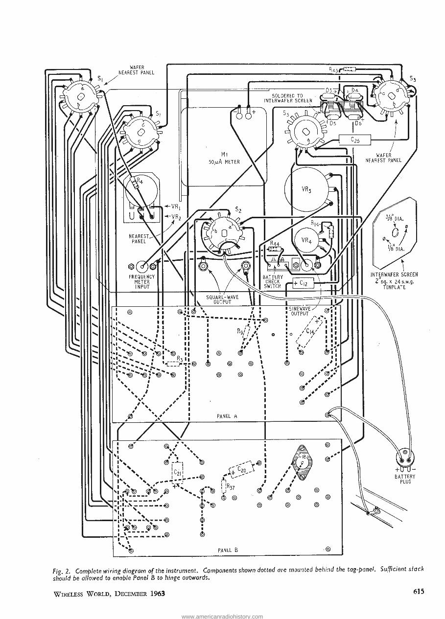
.....
.....
.....
.....
..... .....
.....
.....
FREQUENCY METER INPUT
@ I I lA\ • I J. ... 'I I I I ~.:1\81 \. I I
..1 I I i-••••-••• . 16 I 1'-, I I 1 1 •••:i~-@
"I ' I I I I ,.(, ' ' ... .... I I R ., #
~· .... .. I I I I 9/ I '·
, ' ' I I •'' I' ' ' t I _., # I
,a '- ' ' I I I I# I ~ ' .,1 ' I", ', ,• .... I I#
"I .. ~ '@ ·~I '@ I I @ ~ 1 ..... .... ... : I R3 I I ' .,I .. .,. ... ... I ,.,----;-- @ ~ @ @ \ ...-- ........ ~ ............ :--.... '---- '
I"' ....... .. ... ' I "''@ "@ :'''@ .. '@ @ @
', I \
' I I ~, I ~ I
~ I I I
'* ~~ I
' ' ' I # ' ~ I ', , I
,@ ~~ PANEL A I
I I
~ I I
~
@
PANEL B
0 0
@
@
@ @
@
INTERWAFER SCREEN 2"sq. x 24 s.w.g.
TINPLATE
BATTERY PLUG
Fig. 2. Complete wiring diagram of the instrument. Components shown dotted are mounted behind the tag-panel. Sufficient slack
should be allowed to enable Panel B to hinge outwards.
WIRELESS WORLD, DECEMBER 1963 615
si3
WAFER NEAREST PANEL
?V35» *
m m SOLDERED TO INTERWAFER SCREEN
fl k w,
50/ih METER
NEAREST, PANEL
FREQUENCY METER INPUT
BATTERY CHECK
SWITCH
SQUARE-WAVE OUTPUT
, *1^ %
"Jx! ISX %x '»»
l© ® ® '"I-C'-X • 1—53 1 * % ■ ^ ^
v :
\ / % ^
'*i • * Rq///
V / » It I
<3 \
SINEWAVE OUTPUT
© d) ® ®
® ®
PANEL A
^ ®l ^ I
/ A i:
/civ' •! / z i • >./ i •;< © <&• j
® y
WAFER NEAREST PANEL
Wdia. \ ffl
/ '/B'DIA
INTERWAFER SCREEN C sq. x 24 s.w.g.
TINPLATE
i x
S!" V
_ * >
s\ % V ' *
"fT-
O
1
1- 1
® 1 t 1
+*; © t
© (j) *© 1
© ® ■
©
C, C20 ,i
! !Ry7 s U 37
® ®
1 ' i / ^ ■ / t / '
* / * <3 f <3
3) © © ©
+iru- BATTERY
PLUG
PANEL B
Fig. 2. Complete wiring diagram of the instrument. Components shown dotted are mounted behind the tag-panel. Sufficient slack should be allowed to enable Panel 6 to hinge outwards.
Wireless World, December 1963 61^
www.americanradiohistory.com

(a) (b) (c)
(d) (e) (f)
Fig. 3. ·Some examples of the use of the Signal Generator in amplifier testing. (a) shows a square wave which has not been distorted by the amplifier, while at (b) and (c), the square wave has been distorted by a poor low- and high-frequency amplifier response respectively. At (d) is seen the effect of a peak in the amplifier's high frequency response, induCing ringing. The sinewave at (e) contains a large amount (about I 0%) of second-harmonic distortion. A 3-to-1 Lissajous figure at (f) is an example of frequency measurement.
by plotting on graph paper the output of the amplifier at as many frequencies as desired, while keeping the input constant. This is based on the assumption that an accurately calibrated voltmeter or oscilloscope is to be used. If not, the input should be adjusted to keep the same output at each frequency, the meter or oscilloscope simply being used as an uncalibrated indicator and the setting of the ·signal generator controls giving the response.
Square waves are useful as a qualitative indication of amplifier frequency response and phase shift, as shown in the photographs.
Fig. 4. Meter plate for Z. & I. instrument shown, this is actual size. The scale shown above may be cut out and used, but for best accuracy, each meter should be individually calibrated.
4 5 6
0 0
0 ~ 0 FREQUENCY
The above are merely indications of the way in which the instrument can be used. Many others, such as filter testing, frequency measurement, calibration of other instruments, distortion measure- . ment, etc., are within its capabilities, and will be discussed later in the series. Its first use, as far as we are concerned, will be to calibrate the oscilloscope . .
"WIRELESS WORLD" PUBLICATIONS Net By
Price Post RADIO VALVE DATA
Compiled by the staff of " Wireless World . ., 7th Edition 6/- 6/10
RADIO AND ELECTRONIC LABORA-TORY HANDBOOK M. G. Scroggie, B.Sc., M.I.E.E. 7th Edition 55/- 57/3
PRINCIPLES OF TRANSISTOR CIRCUITS S. W. Amos, B .Sc.(Hons.), A.M.J.E.E. 2nd Edition . . 21/- 22/-
HIGH-QUALITY SOUND PRODUCTION AND REPRODUCTION. H. Burrell Hadden . . 42/- 43/5
SOUND AND TELEVISION BROAD-CASTING. . General Principles. K. R. Sturley, Ph.D., B .Sc., M.I.E.E. . . 45f- 46/4
WIRELESS SERVICING MANUAL lOth Edition W. T . Cocking . . 25/- 26/-
T RANSISTOR INVERTERS AND CON-VERTERS Thomas Roddam 42/- 43 /-
ESSAYS IN ELECTRONICS M. G. Scroggie, B.Sc., M .I.E.E. . . 42/- 43/1
MICROPHONES A. E. Robertson, B.Sc.(Eng.), A.M.I.E.E. 2nd Edition . . 75/- 76/2
0 0 A complete list of books is available on application.
--+--'
616
Obtainable from all leading booksellers or from ILIFFE BOOKS LTD., Dorset House, Stamford Street,
London, S.E. l.
WIRELESS WORLD, DECEMBER 1963
Fig. j. Some examples of the use of the Signal Generator in amplifier testing, (a) shows a square wave which has not been dis- torted by the amplifier, while at (b) and (c), the square wave has been distorted by a poor low- and high-frequency amplifier response respectively. At (d) is seen the effect of a peak in the amplifier's high frequency response, inducing ringing. The sine- wave at (e) contains a large amount (about 10%) of second-harmonic distortion. A 3-to-l Lissajous figure at (f) is an example of frequency measurement.
by plotting on graph paper the output of the amp fier at as many frequencies as desired, wl "le keej ng the iput constant. This is based on the assumption that an accurately cal irated voltmeter or oscilloscope is to be used. If not, the nput should be adjusted to keep the same output at each frequency, the meter or oscilloscope simply being used as an uncalibrated indicator and the setting of the signal generator controls g ng the response.
Square waves are useful as a qualitative indication of amplifier frequency response and phase shift, as shown in the photographs.
Fig. 4. Meter plate for Z. & /. instrument shown, this is actual size. The scale shown above may be cut out and used, but for best accuracy, each meter should be individually calibrated.
£ o
FREQUENCY
The above are merely n( cat >ns of the way in wl ch the istrument can be used. Many others, such as filter testing, frequency measurement, cali- bration of other instruments, distortion measure-, ment, etc., are wnl n its capabil ies, and v 11 be discussed later in the series. Its first use, as far as we are concerned, will be to calibrate the oscillo- scope. .
"WIRELESS WORLD" PUBLICATIONS
RADIO VALVE DATA Compiled by the staff of " Wireless World." 7th Edition .. .. .. 6/- 6/10
RADIO AND ELECTRONIC LABORA- TORY HANDBOOK M. G. Scroggie, B.Sc., M.I.E.E. 7th Edition .. .. .. .. 55/- 57/3
PRINCIPLES OF TRANSISTOR CIR- CUITS S. W Amos, B.Sc.(Hons.), A.M.I.E.E. 2nd Edition .. .. .. .. .. 21/- 22/-
HIGH-QUALITY SOUND PRODUCTION AND REPRODUCTION. ^ Burrell Hadden .. ., 42/- 43/5
SO JND AND TELEVISION BROAD- GA5 TN< General T [pies. K. R. Sturley, Ph.D., B.Sc., M.I.E.E. .. .. 45/- 46/4
WIRELESS SERVICING MANUAL 10th Edition W. T. Cocking .. .. 25/- 26/-
TRANSISTOR INVERTERS AND CON- VERTERS Thomas Roddam .. .. .. .. 42/- 43/-
ESSAYS TN ELECTRONICS M. G. Scroggie, B.Sc., M.I.E.E. .. .. 42/- 43/1
MICROPHONES A. E. Robertson, B,Sc.(Eng.), A.MA.E.E. 2nd Edition 75/- 76/2 A complete list of books is available on application.
Obtainable from all leading booksellers or from ILIFFE BOOKS LTD., Dorset House, Stamford Street,
London, S.E.1,
616 Wireless World, December 1963
www.americanradiohistory.com

DECEMBER, 1963 VVIRELESS ~ORLD
THE MARCONI HU126
• Automatic phasing
. • Self-synchronizing
• Printed record of any channel or
any sub-channel.
The HU126, an item in the Marconi
AUTOPLEX range of error correct·
ing multiplex telegraph equipment,
is Ferritransistorized and uses
modular construction. Bein-g a
self-contained unit with its own
power supplies and crystal oscillator,
it can be used with any type of
ARQ equipment* and quite indepen·
dently of the ARQ terminals.
* in accordance with CCIR Recommendation No. 242 and/or Report No. 108 (Los Angeles 1959)
TELECOMMUNICATIONS SYSTEMS
COMMUNICATIONS DIVISION THE MARCONI COMPANY LIMITED. CHELMSFORD. ESSEX. ENGLAND H118
JWW--1 17 FOR FURTHER DETAILS.
79 December, 1963 Wireless World 79
H
MARCONI HU126
SELF CONTAINED
7-UNIT MONITOR
PROVIDES
MONITORING OF
ARQ AGGREGATE
SIGNALS*
INDEPENDENTLY OF
THE ARQ TERMINAL
nTg-iiiT-*¥11"
I 1 V-
Automatic phasing
Self-synchronizing
Printed record of any channel or
any sub-channel.
The HU126, an item in the Marconi
AUTOPLEX range of error correct-
ing multiplex telegraph equipment,
is Ferritransistorized and uses
modular construction. Bem<j a
se'f-contained unit with its own
power supplies and crystal oscillator,
it can be used with any type of
ARQ equipment* and quite indepen-
dently of the ARQ terminals.
* in accordance with CCIR Recommendation No. 242 and/o*-
Report No. 108 (Los Angeles 1959)
TELECOMMUNICATIONS SYSTEMS
COMMUNICATIONS DIVISION THE MARCONI COMPANY LIMITED. CHELMSFORD. ESSEX. ENGLAND HUB
3WW—117 FOR FURTHER DETAILS.
www.americanradiohistory.com

80 VVIRELESS ~ORLD DECEMBER, 1963
,... - ,... ... IL n THE1 r ,,. ........ J1
... II
lr- ..
... ~ ... ..... \... ~~ ... .... .... .... --MIDGET 'Printact' Plug-in Printed Circuit Relay
The highly reliable Printact Relay, which mounts on and becomes an integral par-t of your printed circuit board, makes possible substantial savings in space, weight and assembly costs. Mechanical linkage and fixed contacts on the relay -are eliminated entirely. The moving contacts which are part of the armature assembly, mate with rhodium over nickel-plated copper conductors printed on your circuit board. -Spring connectors on the coil leads eliminate soldering.
Fully encapsulated in a ~in. high·impact plastic cube, the Printact relay employs a permanent magnet in place of a return spring to hold the armature open. The magnetic force remains constant eliminating the need for maintenance adjustment. Recommended configurations for your circuit layout, provide for switching up to three form A and B or form C, or up to five pole to a common line.
Coil resistance of the standard 6, 12 and 24 volt D.C. relays are 75,300, and 1,200 ohms (500 milliwatts) with pull-in occurring at
* NO SPRINGS
* NO WIRING
* NO SOLDERING
* NO MECHANICAL LINKAGES
t * NO EXPOSED PARTS _]
80% of rated voltage. Variations of coil resistance are available on speciaL order.
Operating life exceeds 5,000,000 operations when contact load is from -dry circuit up to -! amp 24 volts D.C.
Contact Material ... Power Consumption Operating Temperature ... Operate Time Dimensions and Weight Dielectric Test
Gold alloy or Palladium ... 500 mw (at rated voltage)
-30°C, to +95°C. ... 3 to 7 ms. at rated voltage
i X i X ff-0.8 OZ,
1000 volts RMS 60 cps.
Other Printact features include Bifurcated contacts; Double-break contacts; Balanced armature; Enclosed housing; Plug-in ·application; Encapsulated coil; Self-wiping contacts; Inherent snap-action, .greater switching versatility.
ALSO A LATCHING RELAY USJNG CERAMIC MAGNET Cost of inexpensive latching Relay is less than half that of competitive relays because of " Printact " permanent ceramic magnet latching principle and balanced armature which eliminates all mechanical linkage. Reliability has been shown by mechanical life tests exceeding 108 cy and electrical tests exceeding 5 x 10⁶ cy.
Sole distributors for · r rintact ' . Relays :
Available with single or double coil, relay features bifurcated contacts of gold alloy or palladium. D-e pulse of 7 ms duration at rated voltage will switch snap action relay. Single coil unit is rated 500 mw and switches d-e polarity to switch modes. Two-coil unit is rated l·w and uses one coil for switching in and other for switching out.
A.D.S RELAYS LTD. 89-97 St. John Street, london, E.C.I. Tel: CLE.rkenwell 3393
3WW - -118 FOR FURTHER DETAILS.
80 Wireless World December, 1963
MIDGET
'Printact' Plug-in Printed Relay
Sj
ic NO SPRINGS
if NO WIRING
it NO SOLDERING
it NO MECHANICAL LINKAGES
it NO EXPOSED PARTS
The highly reliable Prlntact Relay, which mounts on and becomes an integral part of your printed circuit board, makes possible substantial savings in space, weight and assembly costs. Mechanical linkage and fixed contacts on the relay are eliminated entirely The moving contacts which are part of the armature assembly, mati with rhodium over nickel-plated copper conductors printed on your circuit board. - Spring connectors on the coil leads eliminate soldering.
Fully encapsulated in a sin. high-impact plastic cube, the Printact relay employs a permanent magnet in place of a return spring to hold the armature open. The magnetic force remains constant eliminating the need for maintenance adjustment. Recommended configurations for your circuit layout, provide for switching up to three form A and B or form C, or up to five pole to a common line.
Coil resistance of the standard 6, 12 and 24 volt D.C. relays are 75,300, and 1,200 ohms (500 milliwatts) with pull-in occurring at
80% of rated voltage. Variations of coil resistance are available on special, order.
Operating life exceeds 5,000,000 operations when contact load is from dry circuit up to i amp 24 volts D.C.
Contact Material Gold alloy or Palladium Power Consumption 500 mw (at rated voltage) Operating Temperature —30oC. to 44VC Operate Time 3 to 7 ms. at rated voltage Dimensions and Weight fx x H—41.8 oz. Die jctric Test 1000 volts RMS 60 cps.
Other Printact features include Bifurcated contacts; Double-break contacts; Balanced armature; Enclosed housing; Plug-in application; Encapsulated coil; Self-wiping contacts; Inherent snap-action, greater switching versatility.
ALSO A LATCHING RELAY USING CERAMIC MAGNET Cost of inexpensive latching Relay is less than half that of competitive relays because of " Printact " permanent ceramic magnet latching p nciple and balanced armature which eliminates all mechanical
nkage. Reliability has been shown by mechanical life tests exceeding I08 cy and electrical tests exceeding 5 x I06 cy
Available with single or double coil, relay features bifurcated contacts of gold alloy or palladium. D-c pulse of 7 ms duration at rated voltage will switch snap action relay. Single coil unit is rated 500 mw and switches d-c polarity to switch modes. Two-coil unit is rated I-w and uses one coil for switching in and other for switching out.
So/e distributors for f rintact' Relays :
A.D.S RELAYS LT 3.
89-97 St. .rfohn Street, Lonrton, E.C1. Teh CLErkenwell 3393
3W W"l18 FOR FURTHER DETAILS.
www.americanradiohistory.com
LETTERS TO THE EDITOR
The Editor does not necessarily endorse opwzons expressed by his correspondents
N.T.S.C. Colour I READ with interest the editorial comment and the article on colour television in your September, 1963, issue. I must, · however, comment on some questions raised in the article.
In the last 8 or 9 years there has been a considerable
improvement in the stability and " usability" of colour
TV receivers. Actuarial statistics supplied by RCA Service Co. (and supported by the writer's experience) indicate that colour receivers require little or no more
servicing than their black-and-white cousins. Because of the cost of replacing the c.r.t., most colour set owners carry some sort of servicing insurance policy, the premium for which is only slightly greater than that for a black-and-white set.
With regard to control knobs, the only controls accessible to the public (which are not found on a black-andwhite set) are the hue and tint controls. These require no special skill to use; indeed, my 5-year-old daughter has mastered them. One simply turns up the tint control until the colours are bright enough and then adjusts
the hue control for normal flesh tones. The "correct" settings are purely a matter of sub
jective taste. There is only a slight variation possible with the hue setting (unless one favours green or purple flesh tones), but there is considerable variation possible with the tint control. One can go, for example, from black and white through pastel to the most gaudy
colours. Some slight readjustment of both controls is usually
necessary when switching from one station to another, but between different programme sources on the same station this is usually not necessary ·(with the possible exception of film to tape).
Additional colour-control adjustments at the back of the receiver affect the colour temperature of the blackand-white picture as well as convergence, etc., and are usually of the " screwdriver " type.
The vast majority of American colour programmes are on 35mni film using .the Eastman Colour (Kodak)
process or Technicolo-r. Many of these colour programmes (" Bonanza,"
"Wagon Train," "The Greatest Show on Earth," etc.) are already being seen in Britain and could be seen in
colour overnight as soon as a system is chosen for British
colour TV. Bowie, Maryland, U.S.A. B. W. SHEFFIELD
Long Distance Reception on Band IV FOR the past week I have been observing (in monochrome) the B.B.C. experimental colour transmissions on Channel 33, from a poor location some 250 feet above sea level, near Stony Stratford in north Bucks.
On the evening of the 11th October at 2115 EST the receiver was tuned over the band and I was surprised to find three other television signals present, two lower and one higher in frequency than the B.B.C.
The signal on the lowest frequency channel was the strongest and was still being received when observations ceased at 2230. All the transmissions seemed to be of German or Dutch origin. But no sound is available on my experimental receiver.
The aerial in use was a 16-element array designed for the 70-cm amateur band mounted on a rotator. All the European signals were received with the beam bearing east ( 40 degrees north of my Crystal Palace bearing).
On the 12th October no Continental stations were
WIRELESS WORLD, DECEMBER 1963
received until 1250 EST, only one station being strong
enough to resolve a picture, which was a sports programme.
The general public have of late been informed that when UHF . Televis_ion comes into use they will be free of_ the Contmenta] mterference which played such havoc with Band I last summer. l wonder. ·
Wolverton. M. PITTAM
Demonstrating A.C. Theory THE demonstration of a.c. in slow motion described .in the October issue has been extended. Elementary student~ are more familiar with a rotating coil ' in a magnetic field than. with a transistor oscillator, so a v .l.f. al~ernator was devised The prime mover was a motor With an output speed of 4 rev /minute (a suitable motor ~s s_old by H. Franks, ?8-60, New Oxford Street, W.C.l.; It IS made by Teddmgton Controls, Ltd., and has a governor to limit the speed to 4 rev I minute) An Eclipse Major Magnet provided the field. A ca"il was wound with about 500 turns.
The e.m.f. i?duced in a. coil rotating at this speed is of course small; It was amplified by a d.c. transistor amplifier (Fig. 4 on page 271 of the Mullard Reference
~anual). T?e gain is such that it was necessary to mclude a resistor of about 50kD in series with the coil and the input to the amplifier. The output of the amplifier could then be used in place of the transistor oscillator mentioned in the October article.
If it is thought desirable, spokes can be mounted on the coil shaft, to represent rotating vectors, one for the e.m.f. induced in the coil, others for currents in the resistor, capacitor or "inductor." The spoke for the e.m.f. in the coil is co-planar with the coil.
It is instru~tive to ~o~nect th~ output of the amplifier to an oscilloscope tf It contams a d.c. amplifier. If it also contains a timebase that can be set to run at a very low speed (2 cycles per minute) the spot can be seen to rise and fall as it goes from left to right. If the timebase
frequency cannot be made low enough for this, the timebase can be switched off: the spot rises and falls in a vertical line; or the timebase can be set to any frequency above that of the presistence of vision and the whole timebase slowly rises and falls. If the v.l.f.
oscillator is used instead of the rotating coil, the spot, rising and falling as it goes from left to right can be turned into a continuous trace by slowly incre~sing the frequency of the oscillator and timebase.
If some kind reader can suggest a better inductance
simulator than the one described in the October article, I would be grateful for advice. I would like to demonstrate series resonance, but can see no way of doing this with my arrangement. ·
T. PALMER
THE interesting article in your issue of October 1963 on a.c. demonstrations, by Mr. T. Palmer, prompts me to point out the advantages of using a lower frequency even
than 5 c/s; 0.1 to 0.5 c/s allows time for the students to glance from one meter to another, to compare phase,
etc. It is not easy to obtain a good sinusoidal wave form at such low frequencies, nor to stabilize the output voltage, and though a number of commercial v.l.f. signal generators are now available, they are rather expensive. The distortion has to be much better than might be expected; if capacitive currents are demonstrated, the harmonic content of the signal is exaggerated. This was brought home to me when. some years ago, I
617
LETTERS TO THE EDITOR
The Editor does not necessarily endorse opinions expressed by his correspondents
N.T.S.C. Colour
I READ with interest the editorial comment and the article on colour television in your September, 1963, issue. I must, however, comment on some questions raised in the article.
In the last 8 or 9 years there has been a considerable improvement in the stability and " usability " of colour TV receivers. Actuarial statistics supplied by RCA Service Co. (and supported by the writer's experience) indicate that colour receivers require little or no more servicing than their black-and-white cousins. Because of the cost of replacing the c.r.t., most colour set owners carry some sort of servicing insurance policy, the pre- mium for which is only slightly greater than that for a black-and-white set.
With regard to control knobs, the only controls access- ible to the public (which are not found on a black-and- white set) are the hue and tint controls. These require no special skill to use; indeed, my 5-year-old daughter has mastered them. One simply turns up the tint control until the colours are bright enough and then adjusts the hue control for normal flesh tones.
The "correct" settings are purely a matter of sub- jective taste. There is only a slight variation possible with the hue setting (unless one favours green or purple flesh tones), but there is considerable variation possible with the tint control. One can go, for example, from black and white through pastel to the most gaudy colours. , • 11
Some slight readjustment of both controls is usually necessary when switching from one station to another, but between different programme sources on the same station this is usually not necessary (with the possible exception of film to tape). ,, , ,
Additional colour-control adjustments at the back ot the receiver affect the colour temperature of the black- and-white picture as well as convergence, etc., and are usually of the "screwdriver" type.
The vast majority of American colour programmes are on 35mm film using the Eastman Colour (Kodak) process or Technicolor. )5
Many of these colour programmes ( Bonanza, " Wagon Train," " The Greatest Show on Earth," etc.) are already being seen in Britain and could be seen in colour overnight as soon as a system is chosen for British colour TV.
Bowie, Maryland, U.S.A. B. W. SHEFFIELD
Long Distance Reception on Band IV
FOR the past week I have been observing (in mono- chrome) the B.B.C. experimental colour transmissions on Channel 33, from a poor location some 250 feet above sea level, near Stony Stratford in north Bucks.
On the evening of the 11th October at 2115 BST the receiver was tuned over the band and I was surprised to find three other television signals present, two lower and one higher in frequency than the B.B.C.
The signal on the lowest frequency channel was the strongest and was still being received when observations ceased at 2230. All the transmissions seemed to be of German or Dutch origin. But no sound is available on my experimental receiver.
The aerial in use was a 16-element array designed for the 70-cm amateur band mounted on a rotator. All the European signals were received with the beam bearing east (40 degrees north of my Crystal Palace bearing).
On the 12th October no Continental stations were
received until 1250 BST, only one station being strong enough to resolve a picture, which was a sports pro- gramme.
The general public have of late been informed that when UHF Television comes into use they will be free of the Continental interference which played such havoc with Band I last summer. I wonder.
Wolverton. M. PITTAM
Demonstrating A.C. Theory
THE demonstration of a.c. in slow motion described in the October issue has been extended. Elementary students are more familiar with a rotating coil in a magnetic field than with a transistor oscillator, so a v.l.f. alternator was devised The prime mover was a motor with an output speed of 4 rev/minute (a suitable motor is sold by H. Franks, 58-60, New Oxford Street, W.C.I.; it is made by Teddington Controls, Ltd., and has a governor to limit the speed to 4 rev/minute). An Eclipse Major Magnet provided the field. A coil was wound with about 500 turns.
The e.m.f. induced in a coil rotating at this speed is of course small; it was amplified by a d.c. transistor ampli- fier (Fig. 4 on page 271 of the Mullard Reference Manual). The gain is such that it was necessary to include a resistor of about 50kO in series with the coil and the input to the amplifier. The output of the ampli- fier could then be used in place of the transistor oscillator mentioned in the October article.
If it is thought desirable, spokes can be mounted on the coil shaft, to represent rotating vectors, one for the e.m.f. induced in the coil, others for currents in the resistor, capacitor or " inductor." The spoke for the e.mi. in the coil is co-planar with the coil.
It is instructive to connect the output of the ampli- fier to an oscilloscope if it contains a d.c. amplifier. If it also contains a timebase that can be set to run at a very low speed (2 cycles per minute) the spot can be seen to rise and fall as it goes from left to right. If the timebase frequency cannot be made low enough for this, the time- base can be switched off: the spot rises and falls in a vertical line; or the timebase can be set to any fre- quency above that of the presistence of vision and the whole timebase slowly rises and falls. If the v.l.f. oscillator is used instead of the rotating coil, the spot, rising and falling as it goes from left to right, can be turned into a continuous trace by slowly increasing the frequency of the oscillator and timebase.
If some kind reader can suggest a better inductance simulator than the one described in the October article, I would be grateful for advice. I would like to demon- strate series resonance, but can see no way of doing this with my arrangement.
T. PALMER
THE interesting article in your issue of October 1963 on a.c. demonstrations, by Mr. T. Palmer, prompts me to point out the advantages of using a lower frequency even than 5 c/s; 0.1 to 0.5 c/s allows time for the students to glance from one meter to another, to compare phase, etc. It is not easy to obtain a good sinusoidal wave form at such low frequencies, nor to stabilize the output volt- age, and though a number of commercial v.l.f. signal generators are now available, they are rather expensive. The distortion has to be much better than might be expected; if capacitive currents are demonstrated, the harmonic content of the signal is exaggerated. This was brought home to me when, some years ago, I
Wireless World, December 1963
www.americanradiohistory.com

decided to design a cheap v.l.f. signal source for this purpose. A motor-drive sine potentiometer seemed an obvious method but small fluctuations · in speed caused pronounced "j:umps " in capacitive current. .
A simple ring-type RC oscillator using "cathode follower " feedback and Metrosil limiters was found to be satisfactory for frequencies as low as 0.01 c/ s, and its design was discussed in Electrical Engineering* July, 1957.
The feedback gives an effective multiplication of the time-constant, allowing 0.1-l.Ot..tF polystyrene capacitors to be used. It has the advantage of giving a three-phase output, and so can be applied directly to show line and phase voltages, presence or absence of currents in the neutral, etc. (This was demonstrated by the writer at the I.E.E. Exhibition of Experiments in June, 1957.) The waveform of the charging current in· a peak rectifier is also readily demonstrated. A · 3-valve version giving an output of SOV peak has been in use for seven years at the S.E. Essex Technical College, and the writer would be pleased to give a copy of the circuit to anyone interested.
M.D. ARMITAGE Northampton College of Advanced Technology,
St. John Street, London, E.C.l.
*Journal of the American Institute of Electrical Engineers (now l.E.E.E. ).-Ed.
Wireless Telegraphy in the Royal Navy SINCE writing my original letter under the above title (page 548, Wireless World, November, 1963), a number of important relevant documents have come to light which give a more complete record of the early Royal Navy wireless experiments than has previously been available.
The most significant of these documents is a statement which was attached to a report from Captain Hamilton, of H.M.S, Defiance, to the Commander-inChief, Devenport, dated 28th January, 1899. According to this statement, the first experiments by (then) Captain Henry Jackson were carried out in December, 1895 as a result of reading the papers of J . C. Bose (Proc. Roy. Soc., Vol. 59A, pp.l60-167: 1895). Jackson's experiments were virtually a repeat of Bose's, using a spring coherer and pitch lenses to concentrate the radio waves on to the coherer. However, to quote the words of the statement, these experiments were carried out with "certainly no idea of Morse signals being possible." In other words, genuine radio transmissions as now understood did not take place in this country until 1896.
The report quoted above was entitled " Statement of Captain Jackson's claims as regards the invention of wireless telegraphy" and was a joint composition of Captain Hamilton and Captain Jackson based on information supplied by the latter, which was prepared in January, 1899 in anticipation of a di~pute over the validity of Marconi's patents. The general conclusion which they reached was that Marconi preceeded Jackson in virtually every particular, and, in their opinion, Marconi's patents held good.
The statement " certainly no idea of Morse signals being possible " refers to the position reached by Jackson in about March, 1896, that neither his studies nor his own di.scoveries had caused him to think in terms of Morse signalling at that time. The problem he was investigating was to find some way of locating torpedo boats without revealing their presence to an enemy by flashing lights, etc., and he probably had not then considered the much wider applications of his invention.
The coherer of filings in a glass tube was not used in these trials until July, 1896, and the first Morse signals were transmitted and received on such a coherer on 20th August, 1896.
Unfortunately, no contemporary record of this experiment has been found. The first of Jackson's trials · for which a detailed description is ·available took place on the 28th August, 1896, and was reported to the Com-
618
mander-in-Chief, Devenport, on the 16th September, 1896. In this trial, the maximum range achieved was only 50 yards. This was soon increased to 100 yards, and in the early months of 1897 signals were sent over one-third of a mile with the same apparatus. (Jackson's report to C.-in-C., Devenport, 22nd May, 1897.)
These reports are of importance not merely for their clarification of the early Royal Navy trials, but also as valuable evidence in the persistent controversy regarding the true inventor of radio. It is now clear that Jackson has no claim to priority over Marconi, either on a basis of initial experiment or of publication, and one source of speculation should thereby be removed from the discussion. This is not intended to denigrate Jackson in any way; on the contrary, by putting his earliest work in true perspective the real value of the services he later rendered to Marconi and to the Royal Navy may be better appreciated.
The Admiralty documents mentioned are in the Public Record Office and are quoted by permission of the Controller of H.M. Stationery Office.
Scampton, Lincoln. ROWLAND F. POCOCK
" Why Coaxial Cables ? " THE article by " Cathode Ray " on transmission lines prompts me to describe a model I have thought carefully about for demonstrating exactly how standing waves are produced. Perhaps one of your readers with more engineering ability and facilities than myself could construct a prototype.
The model would consist essentially of a wide band of transparent tape with an integral number of sine waves drawn along its length. . The band is mounted on rollers and held together along · its length so that incident traveUing and reflected travelling waves are observed when one roller is rotated. The band is passed through a mask which can be placed so as to represent the termination. When the roller is rotated slowly by hand it would be observed that the two waves add to zero at half-wave intervals and to between double amplitude and zero at intermediate points. .
Portsmouth. M. R. HARKNETT
Flutter Distortion I HAVE followed with interest the correspondence
.resulting from the suggestion that a layer of p.t.f.e. film be used to reduce friction between felt pressure pads and. recording tape in order to reduce flutter distortion. No correspondent seems to have had my success with this method. May this not be due to the apparent tendency of the writers to generalize from a particular recommendation?
The original suggestion referred to the application of a p.t.f.e. film only to felt pressure pads. The correspondents, however, appear to be liberally applying p.t.f.e. to tape guides and other metal parts in contact with the recording tape. .
I suggest that if the experimenters restrict the use of p.t.f.e. to felt pressure pads they may have some success with the reduction of flutter distortion. I agree that p.t.f.e. 'is unnecessary and undesirable on chromium-plated tape guides and bearing surfaces. ·
Croydon. W. P. SKINNER
OUR COVER
Air Traffic Control equipment developed at the Royal Radar Establishment, Malvern, which was demonstrated during the conference reported on page 621, is illustrated on this month's front cover. Below the three-dimensional radar scanner are the A.T.C. radar consoles surmounted by computer-fed data tables giving aircraft movements.
(Crown Copyright Photos)
WIRELESS WORLD, DECEMBER 1963
decided to design a cheap v.l.f. signal source for this purpose. A motor-drive sine potentiometer seemed an obvious method but small fluctuations in speed caused pronounced " jumps " in capacitive current.
A simple ring-type RC oscillator using " cathode follower " feedback and Metrosil limiters was found to be satisfactory for frequencies as low as 0.01 c/s, and its design was discussed in Electrical Engineering* July, 1957.
The feedback gives an effective multiplication of the time-constant, allowing 0.1-1.0«F polystyrene capacitors to be used. It has the advantage of giving a three-phase output, and so can be applied directly to show line and phase voltages, presence or absence of currents in the neutral, etc. (This was demonstrated by the writer at the I.E.E. Exhibition of Experiments in June, 1957.) The waveform of the charging current in a peak rectifier is also readily demonstrated. A 3-valve version giving an output of 50V peak has been in use for seven years at the S.E. Essex Technical College, and the writer would be pleased to give a copy of the circuit to anyone interested.
M. D. ARMITAGE Northampton College of Advanced Technology,
St. John Street, London, E.C.I.
^Journal of the American Institute of Electrical Engineers (now I.E.E.E.).—Ed.
Wireless Telegraphy in the Royal Navy
SINCE writing my original letter under the above title (page 548, Wireless World, November, 1963), a number of important relevant documents have come to light which give a more complete record of the early Royal Navy wireless experiments than has previously been available.
The most significant of these documents is a state- ment which was attached to a report from Captain Hamilton, of H.M.S. Defiance, to the Commander-in- Chief, Devonport, dated 28th January, 1899. Accord- ing to this statement, the first experiments by (then) Captain Henry Jackson were carried out in December, 1895 as a result of reading the papers of J. C. Bose (Proc. Roy. Soc., Vol. 59A, pp.160-167: 1895). Jack- son's experiments were virtually a repeat of Bose's, using a spring coherer and pitch lenses to concentrate the radio waves on to the coherer. However, to quote the words of the statement, these experiments were carried out with " certainly no idea of Morse signals being pos- sible." In other v/ords, genuine radio transmissions as now understood did not take place in this country until 1896.
The report quoted above was entitled " Statement of Captain Jackson's claims as regards the invention of wireless telegraphy" and was a joint composition of Captain Hamilton and Captain Jackson based on infor- mation supplied by the latter, which was prepared in January, 1899 in anticipation of a dispute over the validity of Marconi's patents. The general conclusion which they reached was that Marconi preceeded Jackson in virtually every particular, and, in their opinion, Marconi's patents held good.
The statement "certainly no idea of Morse signals being possible" refers to the position reached by Jackson in about March, 1896, that neither his studies nor his own discoveries had caused him to think in terms of Morse signalling at that time. The problem he was investigating was to find some way of locating torpedo boats without revealing their presence to an enemy by flashing lights, etc., and he probably had not then con- sidered the much wider applications of his invention.
The coherer of filings in a glass tube was not used in these trials until July, 1896, and the first Morse signals were transmitted and received on such a coherer on 20th August, 1896.
Unfortunately, no contemporary record of this experi- ment has been found. The first of Jackson's trials for which a detailed description is available took place on the 28th August, 1896, and was reported to the Com-
mander-in-Chief, Devonport, on the 16th September, 1896. In this trial, the maximum range achieved was only 50 yards. This was soon increased to 100 yards, and in the early months of 1897 signals were sent over one-third of a mile with the same apparatus. (Jack- son's report to C.-in-C., Devonport, 22nd May, 1897.)
These reports are of importance not merely for their clarification of the early Royal Navy trials, but also as valuable evidence in the persistent controversy regard- ing the true inventor of radio. It is now clear that Jack- son has no claim to priority over Marconi, either on a basis of initial experiment or of publication, and one source of speculation should thereby be removed from the discussion. This is not intended to denigrate Jack- son in any way; on the contrary, by putting his earliest work in true perspective the real value of the services he later rendered to Marconi and to the Royal Navy may be better appreciated.
The Admiralty documents mentioned are in the Public Record Office and are quoted by permission of the Controller of H.M. Stationery Office.
Scampton, Lincoln. ROWLAND F. POCOCK
"Why Coaxial Cables?"
THE article by " Cathode Ray" on transmission lines prompts me to describe a model I have thought care- fully about for demonstrating exactly how standing waves are produced. Perhaps one of your readers with more engineering ability and facilities than myself could construct a prototype.
The model would consist essentially of a wide band of transparent tape with an integral number of sine waves drawn along its length. The band is mounted on rollers and held together along its length so that inci- dent travelling and reflected travelling waves are observed when one roller is rotated. The band is passed through a mask which can be placed so as to represent the termination. When the roller is rotated slowly by hand it would be observed that the two waves add to zero at half-wave intervals and to between double ampli- tude and zero at intermediate points.
Portsmouth. M. R. HARKNETT
Flutter Distortion
I HAVE followed with interest the correspondence resulting from the suggestion that a layer of p.t.f.e. film be used to reduce friction between felt pressure pads and recording tape in order to reduce flutter distortion. No correspondent seems to have had my success with this method. May this not be due to the apparent ten- dency of the writers to generalize from a particular recommendation ?
The original suggestion referred to the application of a p.t.f.e. film only to felt pressure pads. The corre- spondents, however, appear to be liberally applying p.ti.e. to tape guides and other metal parts in contact with the recording tape.
I suggest that if the experimenters restrict the use of p.t.f.e. to felt pressure pads they may have some success with the reduction of flutter distortion. I agree that p.ti.e. is unnecessary and undesirable on chromium- plated tape guides and bearing surfaces.
Croydon. W. P. SKINNER
OUR COVER
Air Traffic Control equipment developed at the Royal Radar Establishment, Malvern, which was demon- strated during the conference reported on page 621, is illustrated on this month's front cover. Below the three-dimensional radar scanner are the A.T.C. radar consoles surmounted by computer-fed data tables giving aircraft movements.
(Crown Copyright Photos)
618 Wireless World, December 1963
www.americanradiohistory.com

FYUNGDALES B.M.E.W.S. NOW
OPERATIONAL
WITH th~ completion of the Fylingdales project at the end of September the chain of Ballistic Missile Early Warning stations is now operational. The 'three stations-the others are at Clear, Alaska, and Thule, Green,land-provide a radar cover probing some 3,000 miles over the "Eurasian land mass ".
The U.K: station, which is on the Yorkshire moors, differs from the other two in that it is the only one equipped exclusively with tracking radar. At the Green-
Inside one of the three 140-ft diameter radomes showing part of the 84-ft scanner and its . tracking mechanism. The spheres (note the honeycomb construction) and the scanners were manufactureq by the Goodyear Aerospace Corporation. (Right) The horns and reflectors for the tropospheric scatter communications station on the Fylingda/es site.
WIRELESS WORLD, DECEMBER 1963
land base four fixed aerials and one tracking r~dar are used and at Alaska there are three fixed aerials. One of the main reasons for using rotating paraboloids at Fylingdales is because of their capability of tracking not only inter-continental ballistic missiles-the main threat to N. America-but also intermediate range missiles which might threaten the U.K. and Western Europe.
The Fylingdales station is a joint Anglo-American project, the U.K. providing the station buildings and services and the U.S. the radar and data processing equipment. It is an R.A.F. Station, of which Gp. Capt. C. Stephen Betts, C.B.E., is officer commanding, with a nucleus of U.S.A.F. personnel under the command of Col. G. W. Hunt. The technical and tactical operation of the station is in the hands of service personnel but the maintenance of the equipment is undertaken by civilians. These are employed by the "systems contractor," R.C.A. through its U.K. subsidiary R.C.A. (Great Britain). Preparatory to the recruiting and training of civilian staff a team of engineers from R.C.A. (G.B.) spent several months at the parent company's research establishment in the States and some of the R.A.F. personnel have spent some time at the Greenland or Alaska stations.
The Yorkshire site, covering several hundred acres and 800ft above sea level, is dominated by the three spheres each 140ft in diameter. These radomes, which are mounted on the roof of each of the three transmitter buildings, are made up of nearly 1,700 pentagonal and hexagonal panels. Each of these panels is 6in thick and of sandwich construction with polyester-resin fibre-
619
FYLINGDALES
B.M.EW.S. NOW
OPERATIONAL
*>* --A s- ■ ■ .~\i€'i
w n ITH the completion of the Fy ngdales project t the end of September the chain of Ballistic Missile Early Warn ig stations is now operational. The three stations—the others are at Clear, Alaska, and Thule, Greenland—provide a radar cover probing some 3,000 miles over the " Eurasian land mass
The U.K. station, which is on the Yorkshire moors, differs from the other two in that : is the only one equipped exclusively with tracking radar. At the Green-
\
il
Inside one of the three 140-ft diameter radomes showing part of the 84-ft sc fi- ner and its. tracking mechanism. The spheres (note the honeycomb construct- ion) and the scannerswere manufactured by the Goodyear Aerospace Corporation. (Right) The horns and reflectors for the tropospheric scatter communications station on the Fylingdales site.
land base four fixed aerials and one tracking radar are used and at Alaska there are three fixed aerials. )ne of the main reasons for using rotat ig paraboloids at Fylingdales is because of their capability of tracking not only inter-continental ballistic missiles—the main th ;t to N. America—but also intermedia : range missiles which might threaten the U.K. and Western Europ..
The I fiingdales station is a joint A glo-American project, the U.K. providing the station buildings nd services and the U.S. the radar and data p ressing equipment It is an R.A.F. Station, of which Gp. Capt. C Stephen Betts, C.B.E., is officer commanding, with a nucleus of U.S.A.F. personnel under the command of Col. G. W. Hunt. The technical md tact al opera- tion of the station is in the hands of service personnel but the maintenance of the equipment is undertaken by civilians. These are employed the "systen s con- tractor," R.C.A, through its U.K. sub lary R.C.A. (Great Britain). Preparatory to the recruiting and train- ing of civilian staff a team of engineers from R.C.A. (G.B.) spent several months at the parent company's research establishment in the State and some of the R.A.F. personnel have spent some time at the Green- land or Alaska stations.
The Yorkshire site, covering several bundled acres and 800ft above sea level, is dominated by the three spheres each 140ft in diameter. These radomes, which are mounted on the roof of eacl of the three transmitter buildings, are made up of nearly 1,700 pentag nal and hexagc al panels. Each of tb-se panels is 6in thick and of sandwich construction with polyester-resin fibre-
--
9 m
.
mm 5* S
Wireless World, December 1963
www.americanradiohistory.com

station IS utilized to heat some of the " support " buildings.
The Fylingdales site provides an outstanding example of r.f. screening and interference suppression. An interesting feature of the station is the half-mile-long tunnel li~ing the three transmitter buildings. This access tunnel, which is large enough to take big lorries, is made of continuously welded sheets of steel and has sealed doors at either end and at entry points to the buildings. Belling & Lee were responsible for the r.f. screening and for the fitting of r.f. interference suppressors where necessary on equipment on the site. Hundreds of filters rated from 0.5 to · 550 amps-many of them oil filled-have been installed. .
Interior of the access tunnel linking the three radar transmitter buildings. Belling-Lee were responsible for the complete screening of the tunnel and the buildings and B.l. Callenders supplied all the cables.
"Redundancy", or the "belt-and-braces" technique, seems to be the key word at the station for almost everything is duplicated from power supply t o the final outgoing communications links. Talking of communications, mention must be made of the tropospheric scatter station which is housed on the site. It includes what is believed to
glass skins separated by a cellular honeycomb of resinimpregnated paper. Within each of these radomes is an 84ft-diameter paraboloid mounted on a SOft pedestal. Hydraulically operated the scanner can sweep through selected areas of azimuth and elevation over a wide sector to the east and once a target has been detected can be locked on to it to determine, with the aid of computers, whether or not it is a ballistic missile. If it is, its speed, trajectory, probable launch point and general impact area are then calculated. The largest of the three transmitter buildings also houses the computing equipment and operations room.
Computers and Communications . Information on what the radars at each of the sites
"see" m their areas of surveillance is sifted by a complex computation system and significant details are passed on to the U.S. Combat Operations Centre of the North American Air Defence Command at Colorado Springs, Colorado. Data from Fylingdales is also fed into the R.A.F. Fighter Command's control centre at Stanmore, Middx. (which is also linked to the Colorado Springs centre), and to other R.A.F. Operations Centres by means of Ferrarlti data links and display units. It will be obvious that the stations also obtain a lot of useful information on known satellites but this is normally filtered out to leave only data on new objects. To ensure that the three stations are "on the ball" simulated "attacks" by I.C.B.M.s and I.R.B.M.s are. a daily feature of the st3tions' procedure.
Two Elliott type 803 computers have been installed at Fylingdales to process the information relative to . the U.K.
The communications system (provided by W~stern Electric) linking each of the three sites to the Combat Operations Centre employs several methods of transmission including radio, cable and tropospheric scatter, over alternative and sometimes devious routes. It must, however, be stressed that no automatic retaliatory action is taken as a result of information received at the Centr.e, decisions based on the information have to be made by the responsible officers.
It need hardly be said that reliability is essential and to ensure this an elaborate monitoring system is provided. This not only keeps a constant watch on the system as a whole but check points throughout the installation are automatically monitored.
The site has its own power station. Eight Mirrless diesel engines, each developing 4,218 b.h.p., drive the English Electric 4,160V, 3-phasc 60c/s alternators delivering 3,040kW. This is stepped down to three medium voltage supplies (208, 415, and 480) all at 60c/s.. Incidentally the heat generated by the boilers in the power
620
be the largest single room screened enclosure in this country. This was manufactured on the site by Belling & Lee from copper sheets. To ensure that no r.f. is radiated (except from the aerial) double doors forming a trap are fitted.
The Fylingdales station, which is said to have cost some £50M, could provide an absolute minimum warning of four minutes in the event of a missile attack on this country and as much as a fifteen-minute warning for the U.S .A.
Books Received Transistor Inverters and Converters, by Thomas Rod
dam. An expansion of articles previously published on this subject in Wireless World, supplemented from other so\lrces ~d m;lifi~d by th~ auth?r's con<:ept _of workingpomt tra)ectones m negative resistance CifCUlts. Pp. 240. Iliffe Books Ltd., Dorset House, Stamford Street Lon-don, S.E.l. Price 42s. '
Audi~ . and A<;oustics,_ by G. A. Briggs. Another entertammg and mstructive booklet in a series from the pen of this author. It is intended to replace, with other volumes to be published later, his earlier work "Sound ~eproduction," now out of print. Chapter headings mclu~e the ear, resonance, echo and reverberation, transient response, stereo, room acoustics and concert halls and studios. J. Moir, M.I.E.E., has collaborated with contributions on room acoustics and as general sub-editor. Pp. 168, Figs. 140. Wharfedale Wireless Works Ltd., Idle, Bradford, Yorks. Price lOs 6d (lls 6d by post).
Bibliography of Magnetic Recording (1954-1961), compiled by R. E. Hadady. Lists 762 papers from 120 technical journals and includes an index of authors and addresses of cited journals. Pp. 19. Kinelogic Corporation, 29, South Pasadena Avenue, Pasadena, California, U.S.A. Price $2.00.
Television Engineer's Pocket Book, edited by J. P. Hawker. Fourth edition revised and extended by additional matter on u.h.f. tuners, 625 lines and other recent . developments in receiver circuitry. Pp. 279 George Newnes Ltd., Tower House, Southampton Street, London, W .C.2. Price 12s 6d.
Spaceflight Today, edited by K. W. Garland. A collection of papers read before the British Interplanetary Society> including contributions on space communications and electric propulsion techniques. Pp. 254. Iliffe Books Ltd., Dorset House, Stamford Street, London, S.E.l. Price 30s.
WIRELESS WORLD, DECEMBER 1961
Interior of the access tunnel linking the three radar transmitter Belling-Lee were responsible for the complete screening of the the buildings and B.I. Callenders supplied all the cables.
glass skins separated by a cellular honeycomb of resin- impregnated paper. Within each of these radomes an 84ft-diameter paraboloid mounted on a 50ft pedestal. Hydraulically operated the scanner can sweep through selected areas of azimuth and elevation over a wide sector to the east and once a target has been detected can be locked on to it to determine, with the aid of computers, whether or not it is a ballistic missile. If it is, its speed, trajectory, probable launch poin and general impact area are then calculated. The largest )f the three transmitter buildings also houses the computing equipment and operations room.
Computers and Communications Information on what the radars at each of the sites
" see " in their areas of surveillance is sifted by a com- plex computation system and significant details are passed on to the U.S. Combat Operations Centre of the North American Air Defence Command at Colorado Springs, Colorado. Data from Fylingdales is also fed into the R.A.F. Fighter Command's control centre at Stanmore, Middx. (wl :h is also ; inked to the Colorado Springs centre), and to other R.A.F. Operations Centres by means of Ferranti data links and display units. It will be obvious that the stations also obti n a lot of useful information on known satellites but this is norm- ally filtered our to leave only data on new objects. To ensure that the three stations are "on the ball" simu- lated " attacks" by I.C.B.M.s and I.R.B.M.S are a daily feature of the stations' procedure.
Two Elliott type 803 computers have been nstalled at Fylingdales to process the information relative to the U.K.
The communications system (provided by Western Electric) link ig each of the three sites to the Combat Operations Centre employs several methods of trans- mission including radio, cable and ropospheric scatter, over alternative and sometimes devious routes. It must, however, be stressed that no automatic ret? atory action is taken as a result of information received at the Centre, decisions based on the i) formation have to be made by the responsible officers.
It need hardly be said that reliability is essential and to ensure this an elaborate monitoring system is pro- vided. This not only keeps a constant watch on the system as a whole but check points throughout the installation are automatically monitored.
The site has its own power station. Eight Mirrless diesel engines, each d /eloping 4,218 b.h.p., drive the English Electric 4,160V, 3-phase 60c/s alternators de- livering 3,040kW. This is stepped down to three medium voltage supplies (208, 415, and 480) all at 60c/s, In- cidentally the heat generated by the boilers in the power
station is utilized to heat some of the " support" buildings.
The Fy igdal^s site i ovides an outstand- mmm ing example of r.f. screening and interference |MJ|| suppression. An interesting feature of the
u ilfli station is the half-mile-long tunnel linking the three transmitter buildings. This access
B! tunnel, wl ch is large enough to take big lor es, is made of continuously welded sheets of steel and has sealed doors at either end and
B|||| at entry points to the buildings. Belling & Lee were responsible for the r.f. screening
Slilpi and for the fitting of r.f. interference sup- pressors where necessary on equipment on the site. Hundreds of filters rated from 0.5 to 550 amps—many of them oil filled—have
IKS been installed. " Redundancy ", or the " belt-and-braces "
IT" technique, seems to be the key word at the ■ station for almosi everything is duplicated
■ * from power supply to the final outgoing com- munications links. Talking of com-
buildings. munications, mention must be made of the tunnel and tropospheric scatter station which is housed
on the site. It includes what is believed to be the largest single room screened enclosure
it fis country. This was manufactured on. the site by Belling & Lee from copper sheets. To ensure that no
f. is radiated (except from the aerial) double doors ft • ing trap are fitted.
The FylingdaL stat* ir, which is said to have cost some £50M, c uld j ot de an absolute minimum warn- ing of four minutes in the event of a missile attacx on this country and as much as a fifteen-minute warning for the U.S.A.
Books Received
Transistor Inverters and Converters, by Thomas Rod- dam. An expansion of articles previously published on this subject Li Wireless World, supplemented from other sources and unified by the author's concept of working- point trajectories in negative resistance circuits. Pp. 240. Iliffe Books 1 ., Dorset House, Stamford Street, Lon- don, S.E.I. Price 42s.
Audio and ousticr by G. A. Briggs. Another entertaining and instructive booklet in a series from the pen of this author. It is intended to replace, with other volumes to b published later, his earlier work "Sound Renrr luct. m" now out of print. Chapter headings include the ear, resonance, echo and reverberation, transient response, stereo, room acoustics and concert ha s and studios. J. Moir, M.I.E.E., has collaborated with contributions on room acoustics and as general t al ditor. Pp. 168 Figs. 14C Wharfedale Wireless Works Ltd., Idle, Bradford, Yorks. Price 10s 6d (11s 6d by post).
Bibliography of Magnetic Recording (1954-1961), compilec by R E. Hadady. Lists 762 papers from 120 technical journals and includes an index of authors and addresses of cited journals. Pp. 19. Kinelogic Cor- ponric 2>, South Pasadena Avenue, Pasadena, Cali- forr t, U.S.A. Price $2.00.
Television Engineer's Pocket Book, edited by J. P. Hawker. Fourth edition revised and extended by addi- tional matter on u.h.f. tuners, 625 lines and other recent. developments in receiver e :uitry. Pp. 279 George Newnes Ltd., Tower House, Southampton Street, London, W.C.2. Price 12s 6d.
Space! ght Today, edited by K W. Gatland. A col- lection of papers read before the British Interplanetary Society, including contributions on space communica- tions and electric propulsion techniques. Pp. 254. Iliffe Books Ltd., Dorset House, Stamford Street, London, S.E.I. Prre 30s.
620 Wireless World, December 1963
www.americanradiohistory.com

ELECTRONICS FOR CIVIL AVIATION RESEARCH AND DEVELOPMENT DISCUSSED AT RECENT SYMPOSIA
EvER since the first balloon observer used a telephone instead of a megaphone, air communications and ·navigation aids have been growing steadily. Until 1939, £100 or so would buy all the equipment needed for a civil aircraft, but the phenomenal advance of electronic engineering in the past twenty-five years has transformed the ironmongery /electronics ratio to something like 2 : 1 on a cost basis.
" Wireless " still has an important part to play, and will have as long as it is considered that aircrews are more reliable than computers. Navigation and air traffic control account for a large percentage of research and development effort, and automatic landing is still being closely studied; indeed the VC10 and Trident were designed with this in mind from the start.
During September, a series of international symposia on the subject were held at Malvern and Farnborough, and the Institution of Electrical Engineers held a conference to round the proceedings off; the papers presented at the I.E.E., while not being all-embracing, d0 give a fairly comprehensive look at the field.
Automatic Landing .
Several papers were pres·ented on automatic landing equipment, being concerned, in the main, with i.l.s. (instrument landing systems). Normally, the beacon is placed at the up-wind end of the runway, its beam inclining slightly upwards. This positioning causes trouble in two main respects. The aircraft makes its final approach to the runway well below the main lobe of the beacon, which means that reflections from other aircraft or buildings ·may be as strong as or stronger than the direct transmission. Secondly, it may not always be possible to site the beacon in the ideal spot and a compromise must be made. A paper by S. S. D. Jones of R.A.E. described a down-wind localizer producing a "fan" pattern along the runway, so that the aircraft is in the beam at all times. The pattern is narrow laterally, so that reflections are cut to a minimum, and both field strength and accuracy are greatest at the touchdown, where they are most needed.
The problem of reflections from other aircraft mentioned above was emphasized in a paper by F . R. Gill and P. England, of B.L.E.U. The mechanism of the interference takes the form of a Doppler frequency shift between the direct and reflected beams, both aircraft being in motion relative to the localizer beacon. For a shift of 90c/s (one of the modulating signals is 90c/s) several flight paths can be calculated, and have been measured by means of a mechanical model. From measurements at Xband of reflections from a model Comet (a typical case) it appears that the best way to avoid reflections
WIRELESS WORLD, DECEMBER 1963
is to clear an air space which could be contained in a cylinder 40,000ft high and 6 nautical miles in radius. This seems a little impracticable, and much more work is necessary to avoid this trouble. Back to leader cable, possibly?
This equipment is, of course, intended for landings in poor visibility, but the conference was reminded by one spt~aker that accidents in the landing phase occur in good visibility, and that the equipment should be used in a monitoring role for all landings. This will probably happen anyway, for the process of proving a reliability of 1 part in 10' is going to need a considerable number bf landings.
The need for automatic landing in conventional (winged) aircraft is fairly obvious. They do not have a monopoly of approach and landing problems, however; helicopters also have their peculiar difficulties, and the logical use of these aircraft, that is between city centres, will render them more acute. D. F. Fance, of R.A.E., pres·ented a paper on the use of the interferometer principle for the guidance of helicopters and other vertical take-off aircraft. The · requirements of such a system are (a) guidance along a steep approach path to avoid high buildings, (b) guidance in several directions for simultaneous handling of more than one aircraft, (c) guidance round small obstacles within an approach sector and (d) overshoot guidance. The principle is to measure, from the ground, the range, height and bearing of each aircraft, derive by computer the information required by the aircraft flying controls to achieve the laid-down flight path, and then to transmit this information by radio link to the aircraft. The interferometers consist of four pairs of aerials separated by different numbers of aircraft-beacon wavelengths, two pairs having a N-S base line, and the other two facing E-W. These give a reading of bearing, phase-slip at a fifth aerial in modulation transmitted by radio-link to the aircraft and retransmitted by the aircraft beacon gives slant range, · and the aircraft's position is accurately defined.
Air Traffic Control
Air traffic control has been responsible for a great deal of development work in primary and secondary radar and methods of display.
The congested state of the electromagnetic spectrum is not confined to medium waves, but has already spread to the 600Mc/ s radar band, where television is a strong challenger. In the remaining . part of the band, . there is danger of interference between radars, and· G. D. Speake, of Marconi, described a method · of overcoming this. Pulses received are fed to two channels, one of which contains a delay equal to the time between pulses. The outputs of the two channels feed a coincidence detector (an AND gate.) which only gives an output
621
ELECTRONICS FOR CIVIL AVIATION
RESEARCH AND DEVELOPMENT DISCUSSED AT RECENT SYMPOSIA
EvER since the first balloon observer used a tele- phone instead of a megaphone, air communica- tions and navigation aids have been growing steadily. Until 1939, £100 or so would buy all the equipment needed for a civil aircraft, but the phe- nomenal advance of electronic engineering in the past twenty-five years has transformed the iron- mongery/electronics ratio to something like 2:1 on a cost basis.
" Wireless" still ha s an important part to play, and will have as long as it is considered that air- crews are more reliable than computers. Navigation and air traffic control account for a large percentage of research and development effort, and automatic landing is still being closely studied; indeed the VC10 and Trident were designed with this in mind from the start.
During September, a series of international sym- posia on the subject were held at Malvern and Farnborough, and the Institution of Electrical Engineers held a conference to round the proceed- ings off; the papers presented at the I.E.E., while not being all-embracing, do give a fairly comprehensive look at the field.
Automatic Landing
Several papers were presented on automatic land- ing equipment, being concerned, in the main, with i.l.s. (instrument landing systems). Normally, the beacon is placed at the up-wind end of the runway, its beam inclining slightly upwards. This position- ing causes trouble in two main respects. The air- craft makes its final approach to the runway well below the main lobe of the beacon, which means that reflections from other aircraft or buildings -may be as strong as or stronger than the direct transmis- sion. Secondly, it may not always be possible to site the beacon in the ideal spot and a compromise must be made. A paper by S. S. D. Jones of R.A.E. described a down-wind localizer producing a "fan" pattern along the runway, so that the air- craft is in the beam at all times. The pattern is narrow laterally, so that reflections are cut to a minimum, and both field strength and accuracy are greatest at the touchdown, where they are most needed.
The problem of reflections from other aircraft mentioned above was emphasized in a paper by F. R. Gill and P. England, of B.L.E.U. The mech- anism of the interference takes the form of a Dop- pler frequency shift between the direct and reflected beams, both aircraft being in motion relative to the localizer beacon. For a shift of 90c/s (one of the modulating signals is 90c/s) several flight paths can be calculated, and have been measured by means of a mechanical model. From measurements at X- band of reflections from a model Comet (a typical case) it appears that the best way to avoid reflections
is to clear an air space which could be contained in a cylinder 40,000ft high and 6 nautical miles in radius. This seems a little impracticable, and much more work is necessary to avoid this trouble. Back to leader cable, possibly?
This equipment is, of course, intended for land- ings in poor visibility, but the conference was reminded by one speaker that accidents in the land- ing phase occur in good visibility, and that the equipment should be used in a monitoring role for all landings. This will probably happen anyway, for the process of proving a reliability of 1 part in 107 is going to need a considerable number "of landings.
The need for automatic landing in conventional (winged) aircraft is fairly obvious. They do not have a monopoly of approach and landing problems, how- ever; helicopters also have their peculiar difficulties, and the logical use of these aircraft, that is between city centres, will render them more acute. D. F. Fance, of R.A.E., presented a paper on the use of the interferometer principle for the guidance of helicop- ters and other vertical take-off aircraft. The re- quirements of such a system are (a) guidance along a steep approach path to avoid high buildings, (b) guidance in several directions for simultaneous hand- ling of more than one aircraft, (c) guidance round small obstacles within an approach sector and (d) overshoot guidance. The principle is to measure, from the ground, the range, height and bearing of each aircraft, derive by computer the informa- tion required by the aircraft flying controls to achieve the laid-down flight path, and then to trans- mit this information by radio link to the aircraft. The interferometers consist of four pairs of aerials separated by different numbers of aircraft-beacon wavelengths, two pairs having a N-S base line, and the other two facing E-W. These give a reading of bearing, phase-slip at a fifth aerial in modulation transmitted by radio-link to the aircraft and re- transmitted by the aircraft beacon gives slant range, and the aircraft's position is accurately defined.
Air Traffic Control
Air traffic control has been responsible for a great deal of development work in primary and secondary radar and methods of display.
The congested state of the electromagnetic spec- trum is not confined to medium waves, but has already spread to the 600Mc/s radar band, where television is a strong challenger. In the remaining part of the band, there is danger of interference between radars, and G. D. Speake, of Marconi, described a method of overcoming this. Pulses received are fed to two channels, one of which contains a delay equal to the time between pulses. The outputs of the two channels feed a coincidence detector (an AND gate) which only gives an output
Wireless World, December 1963 621
www.americanradiohistory.com

when b@th rp1d.ses are pnesent. Different radars have d~erent pulse recurrence :f1re'l.l1ll:ellcies, .a.nd 'One radar will not operate another' s coincidence gate.
The use of short pulses in primary radar is necessary to obtain good target discrimination, but the r.eliabi[ity on :small targets is dependent on a sufficient mean power, which means that extremely short pulses cannot be used. A method of obtaining a short effective pulse at a high apparent pulse power was described in a paper by A. Kravis et al of Marconi. A sweep generator is arranged to frequency-modulate the transmitter klystron throughout a comparatively long pulse. At the receiver, the pulse is pass·ed t:hwugh frequency-selective delay which delays the frequencies at the beginning of the pulse until those at the end have arrived. The resuit is a very short· pulse of, apparently, -very 'high power although the· transmitter power has not been increased. The performance of an S- or Xband radar with pulse compression is much better in ciuner rejection, as "'holes ~· are revealed in the dutter pattern.
A projected type of a.t.c. radar which is, it could be said, nearly 400 times as efficient as the normal type, was described by W. Hersch, of E.M.I. It is known as a beam-positioning radar and, in contrast to the continuously-turning type which spends most of its time staring at -nothing, only looks at known targets. 98 '7{, "utilization efficiency" is claimed for it, against about 0.25 % for the conventional type. The beam is electronically positioned-no rotating scanner-and p.r.f. is automatically variable to suit the immediate funcr.ion of the radar. In its initial mode of operation, every few seconds, it carries out a complete survey of it~ allotted air space, informing its associated computer of the _position and vectors Df any target found. This information is stored and used later. The search completed, the computer decides, from the information it now has, how often each target must he ., looked at" dejJ-endi11g on its speed and importance in the traffic pattern. All the aircraft can thus be tracked. While doing this, the radar can be coded to carry command signals to aircraft automatic:; equipment, and it appears possible to control air traffic completely automatically. With Mach 5 aircraft, this could well be mandatory. If the maximum amcunt of data is not required from the radar, the rJ. power can be reduced proportionately, and the level of efficiency is retained.
For surveillance radar, D. E. N . Davies, .of Birmingham University, postulated a system -of electronic scanning for additional height-finding. The technique is to transmit a vertical fan beam, the receiving " beam " being scanned vertically over the area of the fan beam during the time of -one pulse. This means that any tar,get excited by the transmitted pulse is seen at least .once by the receiving "beam."
Some details of propgsed improvements in airfield surface-movement .radar were given in a paper by P. H. Walker and D. Cawsey, perhaps the most starti.ing being the proposal to use an aerial rotation rate of 1,000 r;p.m. The point of this is that with the normal ·,three-second wait between "paints" an aircraft can move a considerable distance, even '0Il the ground. Increasing the speed to 300 r.p.m. avoids this problem, but presents a new one, flicker. At 1,000 r.p.m. flicker disappears and persistence of vision allows an entirely new approach. Longpersistence phosphors can be abandoned, which
622
means that stationary echoes, such as runway edges af<!d buildings_, do not cause a build-up of brightness. 'Brightness now corresponds to target reflecting power, and as an aircraft is a better target than the edge of a runway, the result is a bright dot moving along a faint runway-4he .ideal picture. The possibility also arises of having two phosphors. A moving target would then only illuminate the blue phosphor, but a stationary one would cause both blue and orange phosphors to fluoresce, when a magenta paint would be seen.. The resolving power of the Q-band (9mm) radiation is such that the three fins of a Super-Constellation can be seen.
· A method of height-finding by secondary radar was described in a paper by W. Haddock, of G.E:C. The pointer of a barometric altimeter is ·coupled to inductance digitizers which specify the angular ·position of the pointer in binary code. The outputs :of the -digitizers feed bi-stable toggle circuits, which, in turn, feed transistor switches connected across tapping points on a delay line, which give, when interrogated by the secondary radar, a train of pulses, the sequence of which corresponds to the position uf the altimeter pointer.
Displays
Much . work has been done on navigation systems, most of it being concerned with the derivation of positional information, rather than the display to the pilot. In a paper by K. R. Honick, of R.A.E., a method was described of continuously plotting the aircraft's position, together with a line representing its track, superimposed on a coloured map. The map consists of a set of 35mm map transparencies mounted in a grid, which is moved in an optical system. The motors driving the film are presented with information by the normal navigational equipment (Doppler, Loran, etc.). Either track-stabilized or north-stabilized modes are possible and framechanging is automatic.
The ever-increasing speeds of inter-continental aircraft make a tremendous demand on the skills of .air traffic controls, not the least of these being the ability to compreh~~nd a developing traffic pattern
· quickly, displayed as it is on two or more screens. \X'. Hersch, of E.M.I., de·scribed a system whereby
.plan-position, height and a number of . other parameters are displayed on a single screen, and produce a stereoscopic effect. It is primarily .intended as an adjunct to the beam-positioning radar described by the same author, although it can be us-ed with any other type. 'The computer of the b.-p. radar .is fed with information on the positions in space of all aircraft in .the area, and for the purpose of display, this is considered to be a cube. This cube is reproduced in perspective on the screen of a normal cathode-ray tube, controls being available to tilt and rotate the cube. The digital data from the computer is conver~ed first to analogue information and then to co-ordinates, so that the echoes appear in the cube in their correct spatial positions. Depth is perceived by the effect of parallax when the position of the cube is varied. Additional facilities are available, whereby a plane or graticule may be inserted in any of .the three axes and ad.justed to give the exact position of a target; "trails" may be attached to targets, important targets can be made to
~Continued on page 623)
WIRELESS WORLD, DECEMBER 1963
when both pulses are present. Different radars have different pulse recurrence frequencies, and one radar will not operate another's coincidence gate.
The use of short pulses in primary radar is necessary to obtain good target discrimination, but the reliability on small targets is dependent on a sufficient mean power, which means that extremely short pulses cannot be used. A method of obtaining a short effective pulse at a high apparent pulse power was described in a paper by A. Kravis et al of Marconi. A sweep generator is arranged to fre- quency-modulate the transmitter klystron through- out a comparatively long pulse. At the receiver, the pulse is passed through frequeney-seleotive delay which delays the frequencies at the beginning of the pulse until those at the end have arrived. The result is a very short pulse of, apparently, very high power although the transmitter power has not been increased. The performance of an S- or X- band radar with pulse compression is much better in clutter rejection, as " holes " are revealed in the clutter pattern.
A projected type of a.t.c. radar which is, it could be said, nearly 400 times as efficient as the normal type, was described by W. Hersch, of E.M.I. It is known as a beam-positioning radar and, in contrast to the continuously-turning type which spends most of its time staring at nothing, only looks at known targets. 98% "utilization efficiency" is claimed for it, against about 0.25 % for the conventional type. The beam is electronically positioned—no rotating scanner—and p.r.f. is automatically variable to suit the immediate function of the radar. In its initial mode of operation, every few seconds, it carries out a complete survey of its allotted air space, informing its associated computer of the position and vectors of any target found. This information is stored and used later. The search completed, the computer decides, from the information it now has, how often each target must be "looked at" depending on its speed and importance in the traffic pattern. All the aircraft can thus be tracked. While doing this, the radar can be coded to carry command signals to aircraft automatic equipment, and it appears pos- sible to control air traffic completely automatically. With Mach 5 aircraft, this could well be mandatory. If the maximum amount of data is not required from the radar, the r.f. power can be reduced pro- portionately, and the level of efficiency is retained.
For surveillance radar, D. E. N. Davies, of Birm- ingham University, postulated a system of electronic scanning for additional height-finding. The tech- nique is to transmit a vertical fan beam, the receiv- ing " beam " being scanned vertically over the area of the fan beam during the time of one pulse. This means that any target excited by the transmitted pulse is seen at least once by the receiving " beam."
Some details of proposed improvements in airfield surface-movement radar were given in a paper by P. H. Walker and D. Cawsey, perhaps the most startling being the proposal to use an aerial rotation rate of 1,000 r.p.m. The point of this is that with the normal three-second wait between "paints" an aircraft can move a considerable distance, even on the ground. Increasing the speed to 300 r.p.m. avoids this problem, but presents a new one, flicker. At 1,000 r.p.m. flicker disappears and persistence of vision allows an entirely new approach. Long- persistence phosphors can be abandoned, which
means that stationary echoes, such as runway edges and buildings^ do not cause a build-up of brightness. Brightness now corresponds to target reflecting power, and as an aircraft is a better target than the edge of a runway, the result is a bright dot moving along a faint runway—.the ideal picture. The pos- sibility also arises of having two phosphors. A mov- ing target would then only illuminate the blue phos- phor, but a stationary one would cause both blue and orange phosphors to fluoresce, when a magenta paint would be seen. The resolving power of the Q-band (9mm) radiation is such that the three fins of a Super-Constellation can be seen.
A method of height-finding by secondary radar was described in a paper by W. Haddock, of G.E.C. The pointer of a barometric altimeter is coupled to inductance digitizers which specify the angular position of the pointer in binary code. The outputs of the digitizers feed bi-stable toggle circuits, which, in turn, feed transistor switches connected across tapping points on a delay line, which give, when interrogated by the secondary radar, a train of pulses, the sequence of which corresponds to the position of the altimeter pointer.
Displays
Much work has been done on navigation systems, most of it being concerned with the derivation of positional information, rather than the display to the pilot. In a paper by K. R. Honick, of R.A.E., a method was described of continuously plotting the aircraft's position, together with a line representing its track, superimposed on a coloured map. The map consists of a set of 35mm map transparencies mounted in a grid, which is moved in an optical system. The motors driving the film are presented with information by the normal navigational equip- ment (Doppler, Loran, etc.). Either track-stabilized or north-stabilized modes are possible and frame- changing is automatic.
The ever-increasing speeds of inter-continental aircraft make a tremendous demand on the skills of air traffic controls, not the least of these being the ability to comprehend a developing traffic pattern quickly, displayed as it is on two or more screens.
W. Hersch, of E.M.I., described a system whereby plan-position, height and a number of other para- meters are displayed on a single screen, and produce a stereoscopic effect. It is primarily intended as an adjunct to the beam-positioning radar described by the same author, although it can be used with any other type. The computer of the b.-p. radar is fed with information on the positions in space of all aircraft in the area, and for the purpose of dis- play, this is considered to be a cube. This cube is reproduced in perspective on the screen of a normal cathode-ray tube, controls being available to tilt and rotate the cube. The digital data from the computer is converted first to analogue information and then to co-ordinates, so that the echoes appear in the cube in their correct spatial positions. Depth is perceived by the effect of parallax when the posi- tion of the cube is varied. Additional facilities are available, whereby a plane or graticule may be in- serted in any of the three axes and adjusted to give the exact position of a target; "trails" may be at- tached to targets, important targets can be made to
(Continued on page 623)
622 Wireless World, December 1963
www.americanradiohistory.com

DECEMBER, 1963 WIRELESS WORLD 81
==-Vort@xion TYPE C.B.L.
quality equipment TAPE RECORDER
The Vortexion CBL recorder has had many detail improvements and additions
using the latest stereo deck, " B " type monitoring, after record facilities with
mixing of inputs on each channel and over 6 watts total o~tput. All the usual
features of the '' B " recorder are retained including metering of bias and signal
plus the ability to record the signal from one track to the other together with
additional signal from the mixed inputs. The separate 30/SO ohm balanced line
microphone inputs allow for the microphones to be placed at any distance apart
according to the result required~ The right hand channel may be switched off
entirely when only single channel working is desired. ,
The W.V.A. Recorder is a semi-professional model of the highest quality.
The W.V.B. Recorder is suitable for professional use with after record,
monitoring and echo faci I ities.
The Vortexion 30/SO watt Amplifier can deliver SO watts of speech and music
or over 30 watts of continuous sine wave and the main amplifier has a response of
30 to 20,000 cps within I db at 0.1% distortion and outputs for 4, 7.5, IS ohm and
100 volt line. Models are available with two, three or four mixed inputs which may
be low impedance balanced line microphones, P.U. or Guitar inputs.
The 120/200 watt Amplifier can deliver its full audio power at any frequency
in the range of 30 to 20,000 cps for which the response is accurate within I db with
less than 0.2% distortion at I ,000 cps. It can be used to drive mechanical devices
for which the power is over 120 watts on continuous sine wave. The input is for
I mw. 600 ohms, the output for 100-120 volts or 200-240 volts and additional ·
matching transformers for other impedances are available.
Other items of our manufacture are:
Erase Fa-der Unit for above recorders.
4 Way Mixer with I 0 watt output and tone controls.
Record and Playback Mixer. 2 x 5 Way Stereo Mixers. 12 Way Mixers. 3 Way Mixer and Peak Programme Meter.
4 Way Mixers. 2 way 30/50 ohm in and out stud type Mixers.
Full details and prices of the above on request.
VORTEXION LIMITED, 257-263 The Broadway, Wimbledon, London, S.W.I9
Telephone: LIBerty 2814 and 6242-3 Telegrams: "Vortexion, Wimble, London' '
3WW-119 FOR FURTHER DETAILS.
December, 1963 Wireless World 81
-——Vartexian
quality equipment
TYPE C.B.L.
TAPE RECORDER
*£> IS*
* - ^ - M
<&> i
i«* y <%
The Vortexion CBL recorder has had many detail improvements and additions
using the latest stereo deck, " B " type monitoring, after record facilities with
mixing of inputs on each channel and over 6 watts total output. All the usual
features of the " B " recorder are retained including metering of bias and signal
plus the ability to record the signal from one 1 "ack to the other together with
additional signal from the mixed inputs. The separate 30/50 oLn balanced line
microphone inputs allow for the microphones to be placed at any distance apart
according to the result required. "The right hand channel may be switched off
entirely when only single channel working is desired.
The W.V.A. Recorder is a semi-professional model of the highest quality.
The W.V.B. Recorder is suitable for professional use with after record,
monitoring and echo facilities.
The Vortexion 30/50 watt Amplifier can deliver 50 watts of speech and music
or over 30 watts of continuous sine wave and the main amplifier has a response of
30 to 20,000 cps within I db at 0.1% distortion and outputs for 4, 7.5, 15 oh^i and
100 volt line. Models are available with two, three or four mixed inputs which may
be low impedance balanced line microphones, P.U. or Guitar inputs.
The 120/200 watt Amplifier can deliver its full audio power at any frequency
in the ran e of 30 to 20,000 cps for which the response is accurate within I db with
less than 0.2% distortion at 1,000 cps. It can be used to drive mechanical dev.':es
for which the power is over 120 watts on continuous sine wave. The input is for
I mw. 600 ohms, the output for 100-120 volts or 200-240 volts and additional
matching transformers for other impedances are available.
Other items of our manufacture are:
Erase Fader Unit for above recorders.
4 Way Mixer with 10 watt output and tone controls.
Record and Playback Mixer.
2x5 Way Stereo Mixers.
12 Way Mixers.
3 Way Mixer and Peak Programme Meter.
4 Way Mixers.
2 way 30/50 ohm in and out stud type Mixers.
Full details and prices of the above on request.
VORTEXION LIMITED, 257-263 The Broadway, Wimbledon. London, S.W.I9
Telephone: LIBerty 2814 and 6242-3 Telegrams: "Vortexion. Wimble, London'
3WW—119 FOR FURTHER DETAILS.
www.americanradiohistory.com

S2 VVIRELESS VVORLD DECEMBER, 1963
REVOLUTIO ARY AVAL RADIO TRANSMITTING
SYSTEMS
• Precise frequency setting and positive stability allows full
adva:ntage to be taken of SSB which provides the most rel,iable
communications under difficult conditions of propagation or
interference • Continuous frequency coverage from 240 Kc/s
to 24 Mc/s • Covers alltypesofsignalling•Broadbandamplifier
and synthesizer system provides simplest operation and almost
eliminates tuning • Aerials can be sited for maximum radiating
efficiency.
MARCONI NT 203/204 SYSTEMS COMPLETE NAVAL RADIO AND RADAR SYSTEMS
THE MARCONI COMPANY LiMITED· CHELMSFORD ESSEX ENGLAND
3WW-120 FOR FURTHER DETAILS.
m m
f : m
i
m
f
Complete flexible
systems
for any class of vessel
Adopted by the
Royal Navy and ordered
by navies in
the Commonwealth
and NATO
ii
*
■ Precise frequency setting and positive stability allows full
advantage to be taken of SSB w"r ch provides the most reliable
communications under difficult conditions of propagation or
interference ■ Continuous frequency coverage from 240 Kc/s
to 24 Mc/s ■ Covers alltypesofsignallingBBroadbandamp: fier
and synthesizer system provides simplest operation and almost
eliminates tuning ■ Aerials can be sited for maximum radiating
efficiency.
MARCONI NT 203/204 SYSTEMS
COMPLETE NAVAL RADIO AND RADAR SYSTEMS
THE MARCONI C O M P A N Y L i M IT E D " C H E L M S F O R D ESSEX ENGLAND 3WW—120 FOR FURTHER DETAILS.
www.americanradiohistory.com

flash, and the size of spots can be made to corres
pond to the size of the aircraft.
Television has it3 . applications in aviation, for
instance in flight refuelling, where it is helpful to
the tanker pilot to know exactly where "Baby" is
relative to the pipe-line, Similarly, cameras can be
trained on the leading edges of flying surfaces to give
information on icing, and in test-flying, flutter, air
flow and many uther parameters can be observed.
In many of these applications, viewing conditions
vary greatly, and automatic cameras are extremely
useful. N. N. Parker Smith, of Marconi, described
such a unit. To avoid a deterioration in noise per
formance, a Nuvistor was used as the first stage of
amplificati.on, and transistors from this point on. A
l-in vidicon tube is used with an automatic shutter
to prevent damage should the sun be included in
shot, and a 1000: 1 rar1ge of light levels is automatic
ally accomm_odated by variation of the target voltage.
Black level Is separately stabilized. The vidicon is
operated with a high focusing field, which gives a
small spot, and as the mesh is isolated from the wall
electrode, different potentials are used to give im
proved corner resolution. Linearity of the picture,
taking into account time-base shape and deflection
geometry is such that any point is displayed less
than 1 %' of picture height or width from its true
position.
AIR TRAFFIC C 0 N T R 0 L. R A D A R
VERSA TILE S-BAND SURVEILLANCE EQUIPMEf>JT
lHE conflicting requirements of air traffic control at
low and high altitudes and close and long range are
economically combined in the Decca ARI surveillance
radar. Many advanced features are incorporated, which lead
to an extremely versatile performance and low cost. For
instance, the aerial design is such that coverage is
obtained from a few hundred yards to 75 miles at heights
of 200 feet to over 40,000 feet. A transistor display
can be used, with a range-and-bearing interscan line.
Variable polarization, together with a very e~ective
moving-target indicator, provide an uncluttered d1splay.
The 10-cm aerial is of 16ft aperture, giving a beam
width of 1.5 °, and rotates at 15 r.p.m. The rate of
data renewal thus conforms to I.C.A.O. requirements.
The horn-feed arm contains a twin-vane phase shifter,
so that the relative phases of two components of the
transmitter output can be continuously varied, providing
any type of polarization from linear to circular. The
vanes are controlled remotely by the qperator.
The 650kW peak power transmitters can be used,
working in frequency diversity to provide the required
redundancy and increased protection against r.f. inter
ference. The transmitter cabinet also houses an ex
tremely stable local oscillator (stalo), consisting of a
triode cavity oscillator with a motor-driven a.f.c. system.
Extreme measures are adopted to prevent frequency
modulation by vibration, three sets of bellows-type shock
absorbers in series being used. Any frequency-modula
tion of the stalo would produce spurious phase-shifts
in the receiver i.f., and prevent proper cancellation in
the m.t.i.; lOc/s is the maximum deviation allowed.
Either a linear or a logarithmic response is obtainable
from the transistor receiver, the latter giving an im
provement in clutter rejection and target-to-background
contrast. A low-noise travelling-wave-tube head ampli
fier is housed in the transmitter cabinet. A three
pulse cancellation m.t.i. is used, giving a reduction of
27dB in permanent echoes. A variable control gives
any degree of permanent echo desired, so that the con
troller can be reminded of the existence of obstructions
without obscuring targets. The good low-level coverage of the ARI aerial is
useful in early identification of aircraft on climb-out
from take-off. · Even small fighters have been followed
throughout a climb starting from within t mile of
the aerial. The radar is sufficiently accurate in range
and azimuth, and has adequate discrimination to enable
the equipment to feed aircraft into an i.l.s. pattern.
The equipment is designed in modular form for
ease of installation, while still retaining a wide variety
of possible layouts. ·
WIRELESS WoRLD, DECEMBER 1963
The complete installation. Standard buildings and materials are
used, giving a cheap and simple equipment.
The autonomous transistor display, which provides interscan
lines with variable offset for approaches to remote airfields, and
for range and bearing determination between two targets.
Radar control unit is on right.
623
flash, and the size of spots can be made to corres- pond to the size of the aircraft.
Television has its applications in aviation, tor instance in flight refuelling, where it is ^helpfm to the tanker pilot to know exactly where Baby is relative to the pipe-line. Similarly, cameras can be trained on the leading edges of fly1"' : surfa to give information on icing, and in test-flying, flutter, air- flow and many other parameters can be obseryed. In many of these applications, viewing conditions vary greatly, and automatic cameras are extremely useful. N. N. Parker Smith, of Marconi, described such a unit. To avoid a deterioration in noise per- formance, a Nuvistor was used as the first stage of
amplification, and transistors from this point on. A 1-in vidicon tube s used with an automatic s to prevent damage should the sun be included in shot, and a 1000:1 range of light levels is automatic- ally accommodated by varia mn of the target voltage. Black level is separately stabilized. The vidicon is operated with a high focusing field, which gives a 3 aall spot, and as die mesh is isolated from the v-all electrode, lifferent potentials are isec o give im- proved corner resolution. Linearity of he picture, taking ato account time-base shape and deflection geom try is such that any point i displayed less than 1%' of picture height or width from its true position.
AIR TRAFFIC CONTROL RADAR
VERSATILE S-BAND SURVEILLANCE EQUIPMENT
1 HE conflicting requirements of air traffic control at low and high altitudes and close and long range are economically combined in the Decca AR1 surveillance
"Many advanced features are incorporated, which lead to an extremely versatile performance and low cost For instance, the aerial design is such chat coverage is obtained from a few hundred yards to 75 miles at heijjffi of 200 feet to over 40,000 feet. A transistor display can be used, with a range-and-bearing interscan lineu Variable polarization, together with a veBCem^tive moving-target indicator, provide an uncluttered display.
The 10-cm aerial is of 16ft aperture, giving a beam width of 15° and rotates at 15 r.p.m. Fhe rate of data renewal thus conforms to LC.A.O. requirements. The horn-feed arm contains a twin-vane phase s inter, so that the relative phases of two components ofthe transmitter output can be continuously varied, Provl^| anv type of polarization from linear to circular. The vanes are controlled remotely by the operator.
he rr)kW peak power transrr iters can 1 used, wo dng in freqSa :y di ^rsity to.] ovide the re aired redundancy and increased protection against r.f. uiter- ferenc The transmitt cabinet also 1 mses an ex- tremely stable local osc itor (s k , consistn ; a
ode :avity oscillator w J a motor-driv n a.f.c. sysu Mreme measures are dopted to prevent frequen
lation by vibration, three sets of belle /s yi-: s J* bsorbers in se es being us in f: quenc7"™.0^ift"
tion of the stalo would produce spurious phase-shifts in the receiver i.f., and prevent proper cancellation in t .i.; lOc/s is th^ nax num deviatio all ved.
Either a linear or a logarithmic response i: obtainal from the transistor re eiv< , the latter iv ig an im- r ment in clutter rejection am g< -t0-backg] u <
< trast. A low-noise travelhng-wave-tube head amp fier is housed in the transmitter cabinet. A three- pulse cancellation m.t.i. is used, givmg a reduction o 27dB in permanent echoes. A variable control gives anv degre of permar^ut ch a desired, so tl it tl con- troller an be reminded of the existence of obstructions without obscuring targets. .
The good low-level coverag- of the AR1 aerial is useful in early identiheaten of airc ^ on climb-out from take-off. Even small, fighters have been followed throughout a climb starting from within | mile ot the aeri 1 The radar ie sufficiently accmate in range and azimuth, and has ac equate discrimination to enable the equipme t to feed aircraft ato ai U.S. pattern.
The equipment is -^signed n modular form tor ease of installation, while still retaining a wide variety of possible layouts.
Wireless World, December 1963
:
The complete installation. Standard buildings and materials are used, giving a cheap and simple equipment.
r. : -
The autonomous Lransistor display, which f /ides mterscan ines with variable offset for approaches to i mote ai idds, and
for range and bearing determination between two targets. Radar control unit is on right.
www.americanradiohistory.com

D.C. INVERTER FOR ELECTRIC SHAVERS SQUARE-WAVE "50 c/s 230V" OUTPUT USING CAR BATTERY
By J. R. NOWICKI*
THE inverter described in this article is designed for use with . car batteries, the nominal voltage of which is 12 volts. The circuit operates at 50c/s producing square-wave output voltage equivalent to the 230V a.c. mains.
The inverter was primarily designed for use with mains-voltage electric shavers. Although these shavers are designed to operate from 50cjs sine
· wave they will function satisfactorily from a squarewave inverter provided an adjustment is made to allow for loss of power due to lower peak value of the fundamental component of the waveform.
Basic Inverter Circuit.-In the basic push-pull circuit1 shown in Fig. 1 the transistors act as on-off switches to obtain square wave output from a d.c. supply. This square wave is then stepped up by a transformer to a desired output level. The voltage across the transformer primary is limited by the bottoming of the transistors. The feedback voltage is determined by the supply voltage and the turns ratio between the collector and the base windings. The transformer is made to saturate so that the frequency of the operation is, to a certain extent, independent of load conditions.
The collector current of the conducting transistor has two components: I R' the collector load current and Im, the magnetizing current of the transformer. The magnetizing current, Im, is initially small due to . a high value of the inductance of the primary. When the transformer saturates, the inductance falls and the current increases rapidly to the value of {JIB. Then it can no longer increase so that the voltage across the primary falls. A rapid reversal of voltages, which follows, switches off the transistor that was conducting and switches on the other transistor. A starting circuit is usually required to initiate the oscillations.
Modified Circuit.-The basic circuit as shown in Fig. 1, however, is not satisfactory, because not only does the frequency change when transistors with wide fJ spread are used so that an adjustment is required, but also the peak collector current varies according to the gain of the transistor. High voltage spikes may also appear across the transistor due to the leakage inductance of the transformer. This coupled with a highly inductive load, as in the case of an electric shaver, may cause a transistor failure due to the operation at the high-current and high-voltage avalanche region.
In order to overcome the disadvantages of the basic circuit a modified circuit as shown in Fig. 2 is used. R 1 and R 2 are the usual starting resistors.
The resistor R 3 is connected common to the two
* Semiconductor Measurement and Application Laboratory, Mullard, Southampton Works, Associated Semiconductor Manufacturers Ltd.
624
emitters in order to control the peak collector current to a close value. The capacitor C1 is connected across the secondary to reduce the collector voltage overswing of the cut off transistor due to the high energy stored in the transformer. Another component added is the capacitor c\! which is connected directly across the two collectors to stop spurious oscillations which may be caused by leakage inductance of the transformer windings.
The operation of the modified circuit is similar to that of the basic circuit except that it is slightly modified by the emitter resistor and the capacitor C1 •
Although the modifications improve the operation and reliability of the circuit, its efficiency is reduced considerably, mainly due to the power loss in the emitter resistor R 3• Therefore the usefulness of the inverter is limited to applications where simplicity and initial low cost is of prime importance. For applications especially where high efficiency is required, two-transformer inverters2 or an inverter with CR timinga may be preferred.
Design Considerations
Choice of Transistor Type.-The design of the inverter is based on the available supply voltage and the required output voltage and· power. The supply voltage, which in this case is a car battery, is taken as a nominal value of 12.6 volts. This, however, may vary from 10 to 15 volts. Therefore the output voltage of the inverter is designed to be equivalent to the 230V a.c. mains at the nominal supply voltage of 12.6V which should provide satisfactory operation over the entire range of the
Fig. I. Basic push-pull inverter circuit.
------------~------------~~----------o-Vcc
•
Npi
• TRI
__ ._ ________ _L ________ ~~--------~+
WIRELESS WORLD, DECEMBER 1963
D.C. INVERTER FOR ELECTRIC SHAVERS
SQUARE-WAVE "50 c/s 230V" OUTPUT USING CAR BATTERY
By J. R. NOWICKS*
T M. HE inverter described in this article is designed for use with car batteries, the nominal voltage of which is 12 volts. The circuit operates at 50c/s producing square-wave output voltage equivalent to the 230V a.c. mains.
The inverter was primarily designed for use with mains-voltage electric shavers. Although these shavers are designed to operate from 50c/s sine wave they will function satisfactorily from a square- wave inverter provided an adjustment is made to allow for loss of power due to lower peak value of the fundamental component of the waveform.
Basic Inverter Circuit.—In the basic push-pull circuit1 shown in Fig. 1 the transistors act as on-off switches to obtain square wave output from a d.c. supply. This square wave is then stepped up by a transformer to a desired output level. The voltage across the transformer primary is limited by the bottoming of the transistors. The feedback voltage is determined by the supply voltage and the turns ratio between the collector and the base windings. The transformer is made to saturate so that the frequency of the operation is, to a certain extent, independent of load conditions.
The collector current of the conducting transistor has two components: IB, the collector load current and Im, the magnetizing current of the transformer. The magnetizing current, Im, is initially small due to a high value of the inductance of the primary. When the transformer saturates, the inductance falls and the current increases rapidly to the value of /3Ib. Then it can no longer increase so that the voltage across the primary falls. A rapid reversal of voltages, which follows, switches off the transistor that was conducting and switches on the other transistor. A starting circuit is usually required to initiate the oscillations.
Modified Circuit.—The basic circuit as shown in Fig. 1, however, is not satisfactory, because not only does the frequency change when transistors with wide spread are used so that an adjustment is required, but also the peak collector current varies according to the gain of the transistor. High voltage spikes may also appear across the transistor due to the leakage inductance of the transformer. This coupled with a highly inductive load, as in the case of an electric shaver, may cause a transistor failure due to the operation at the high-current and high-voltage avalanche region.
In order to overcome the disadvantages of the basic circuit a modified circuit as shown in Fig. 2 is used. R, and R2 are the usual starting resistors.
The resistor R3 is connected common to the two
* Semiconductor Measurement and Application Laboratory, Mullard, Southampton Works, Associated Semiconductor Manufacturers Ltd.
emitters in order to control the peak collector current to a close value. The capacitor Q is con- nected across the secondary to reduce the collector voltage overswing of the cut off transistor due to the high energy stored in the transformer. Another component added is the capacitor C2 which is connected directly across the two collectors to stop spurious oscillations which may be caused by leakage inductance of the transformer windings.
The operation of the modified circuit is similar to that of the basic circuit except that it is slightly modified by the emitter resistor and the capacitor Q.
Although the modifications improve the operation and reliability of the circuit, its efficiency is reduced considerably, mainly due to the power loss in the emitter resistor Rg. Therefore the usefulness of the inverter is limited to applications where simplicity and initial low cost is of prime importance. For applications especially where high efficiency is required, two-transformer inverters2 or an inverter with CR timing11 may be preferred.
Design Considerations
Choice of Transistor Type.—The design of the inverter is based on the available supply voltage and the required output voltage and power. The supply voltage, which in this case is a car battery, is taken as a nominal value of 12.6 volts. This, however, may vary from 10 to 15 volts. Therefore the output voltage of the inverter is designed to be equivalent to the 230V a.c. mains at the nominal supply voltage of 12.6V which should provide satisfactory operation over the entire range of the
Fig. I. Basic push-pull inverter circuit.
O-Vcc
? 0
In,
Npig J§Np2
Nfi8 SNfZ «0 0
k •_? c ^—
Tri Tr2
624 Wireless World, December 1963
www.americanradiohistory.com
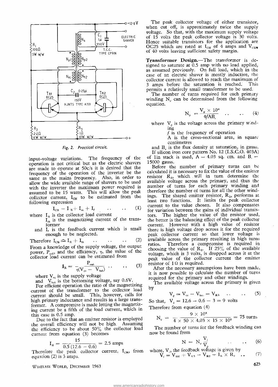
R2
---+--------.,.-------a -12-6 v
ELECTRIC SHAVER
2-2.0. ~6~W~W~/~W-----~~~W~/~W~----------o+
Fig. 2. Practical circuit. ·
input-voltage vanatlons. The frequency of the operation is not critical but as the electric shavers are · made to operate at 50c/s it is desired that the frequency of the operation of the inverter be the same as the mains frequency. Also, in order to allow the wide available range of shavers to be used with the inverter the maximum power required is assumed to be 15 watts. This will allow the peak collector current, IcM to be estimated from the following expression
IcM = I R + Im + If (1)
where In. is the collector load current Im is the magnetizing current of the transformer
and If is the feedback current which is small enough to be neglected.
Therefore IcM ~ IR + Im (2)
From a knowledge of the supply voltage, the output power, PouL' and the efficiency, 'Y], the value of the collector load current can be estimated from
I _ pout
R- ( V) •• 'YJ vee --:- bot
(3)
where Vee is the supply voltage and Vbot is the bottoming voltage, say 0.6V. For efficient operation the ratio of the magnetizing
current of the transformer to the collector load current should be small. This, however, calls for high primary inductance and results in a large transformer. A compromise is made letting the magnetizing current be a fifth of the load current, which in this case is 0.5 amp. · ·
Due to the fact that an emitter resistor is employed the overall efficiency will not be high. Assuming the efficiency to be about 50% the collector load curr~nt from equation (3) b~comes
15 Ill = 0.5 (12.6 - 0.6) = 2.5 amps
Therefore the peak collector current, Io:vD from eqmtion (2) is 3 amps.
WIRELESS WORLD, DECEMBER 1963
The peak collector voltage of either transistor when cut off, is approximately twice the suppl~ voltage. So that, with the maximum supply voltage of 15 volts the peak collector voltage is 30 volts. Hence suitable transistors for the application are OC25 which are rated at IcM of 4 amps and VcEM of 40 volts leaving sufficient safety margin. ·
Transformer Design.-The transformer is designed to saturat~ at 0.5 amp with no load applied, as assumed prevtously. On full load, which in the case of an electric shaver is mostly inductive, the collector current is allowed to reach the maximum of 3 amps before the saturation is reached: This permits a relatively small transformer to be used.
The number of turns required for each primary winding NP can be determined from the following equation.
(4)
where YP is the voltage across the primary w;ndmg f is the frequency of operation . A is the cross-sectional area, in squar~·
centimetres . and Bs is the flux density at saturation, in gauss. If silicon iron core pattern No. 12 (I.S.C.O. 403A)
of lin stack is used, A= 4.03 sq. em. and R =
15000 gauss. Before the number of primary turns can be
calculated it is necessary to fix the value of the emitter resistor R3, which . will in turn determine the available voltage across the primary, and thus tht' number of turns for each primary winding and therefore the number of turns for all the other windings. The shared emitter resistor, R 3, performs at least two functions. It limits the peak collector current to the value chosen. It also compensates for variation between the gains of individual transistors. The higher the value of the resistor used, the better is the balancing effect of the peak collector current. However with a high value of resistor there is high voltage drop across it for the required peak collector cu_rrent so that lower voltage is available across the primary resulting in high turns ratios. Therefore a compromise is required in choosing the value of R 3• If 25% of the available voltage, which is 3 volts) is dropped across it at the peak value of the collector current the emitter resistor of 1 n is required.
After the necessary assumptions have been made, it is now possible to calculate the number of turns required for the primary and other windings.
The available voltage across the primary is given by
VP=Vcc-Vbo~. -VRa (5)
So that, Vp = 12.6 - 0.6 - 3 = 9 volts
Therefore from equation ( 4)
N = . 9 X 1Q8
P 4 X 50 X 4.03 X 15 X 103 = 75 turns
The number of turns for the feedback winding can now be found from
vf N = Np V (6)
jJ
where, vi, the feedback voltage is given by vi= vii);]+ vlt3- vlt2 +Ill x R2 (7)
625
)-l2-6 V
ELECTRIC SHAVER
>R| Jioofl I 3W w/w
T.C.C. TYPE CP9IN
Nfl o fo^fZ
C? 0'25/i ——
I50V HUNTS TYPE A30I
> z-zii 6W W/W
. m ioW w/w
Fig. 2. Practical circuit.
input-voltage variations. The frequency of the operation is not critical but as the electric shavers are made to operate at 50c/s it is desired that the frequency of the operation of the inverter be the same as the mains frequency. Also, in order to allow the wide available range of shavers to be used with the inverter the maximum power required is assumed to be 15 watts. This will allow the peak collector current, ICM to be estimated from the following expression
IcM = I B+ Im + If • • • * (1)
where IR is the collector load current Im is the magnetizing current of the trans- former
and I, is the feedback current which is small enough to be neglected.
Therefore ICM — Ik + Im • • • • • • (2)
From a knowledge of the supply voltage, the output power, Pout,, and the efficiency, 17, the value of the collector load current can be estimated from
vbot) '• .. 0)
where V00 is the supply voltage and Vbot is the bottoming voltage, say 0.6V. For efficient operation the ratio of the magnetizing
current of the transformer to the collector load current should be small. This, however, calls for high primary inductance and results in a large trans- former. A compromise is made letting the magnetiz- ing current be a fifth of the load current, which in this case is 0.5 amp.
Due to the fact that an emitter resistor is employed the overall efficiency will not be high. Assuming the efficiency to be about 50% the collector load current from equation (3) becomes
15 F = = 2.5 amps
K 0.5 (12.6 - 0.6) Therefore the peak collector current, IClVt, from equation (2) is 3 amps.
The peak collector voltage of either transistor, when cut off, is approximately twice the supply voltage. So that, with the maximum supply voltage of 15 volts the peak collector voltage is 30 volts. Hence suitable transistors for the application are OC25 which are rated at ICM of 4 amps and VCBM
of 40 volts leaving sufficient safety margin.
Transformer Design.—The transformer is de- signed to saturate at 0.5 amp with no load applied, as assumed previously. On full load, which in the case of an electric shaver is mostly inductive, the collector current is allowed to reach the maximum of 3 amps before the saturation is reached. This permits a relatively small transformer to be used.
The number of turns required for each primary winding Np can be determined from the following equation.
V x 108
p 4/ABs " ' * ;
where Vp is the voltage across the primary wind- ing / is the frequency of operation A is the cross-sectional area, in square centimetres
and Bs is the flux density at saturation, in gauss. If silicon iron core pattern No. 12 (I.S.C.O. 403A)
of lin stack is used, A = 4.03 sq. cm. and B. = 15000 gauss.
Before the number of primary turns can be calculated it is necessary to fix the value of the emitter resistor R3, which will in turn determine the available voltage across the primary, and thus the number of turns for each primary winding and therefore the number of turns for all the other wind- ings. The shared emitter resistor, Rg, performs at least two functions. It limits the peak collector current to the value chosen. It also compensates for variation between the gains of individual transis- tors. The higher the value of the resistor used, the better is the balancing effect of the peak collector current. However with a high value of resistor there is high voltage drop across it for the required peak collector current so that lower voltage is available across the primary resulting in high turns ratios. Therefore a compromise is required in choosing the value of Rg. If 25% of the available voltage, which is 3 volts, is dropped across it at the peak value of the collector current the emitter resistor of 10 is required.
After the necessary assumptions have been made, it is now possible to calculate the number of turns required for the primary and other windings.
The available voltage across the primary is given by
Vp — Vcc Vbob Vks
So that, Vp — 12.6 — 0.6 —
Therefore from equation (4)
9 volts
9 x 10⁸
4 X 50 X 4.03 X 15 X 103 75 turns
The number of turns for the feedback winding can now be found from
where, V;, the feedback voltage is given by Vf = Vuu + Vks VK2 + Ib X Rg
Wireless World, December 1963 625
www.americanradiohistory.com
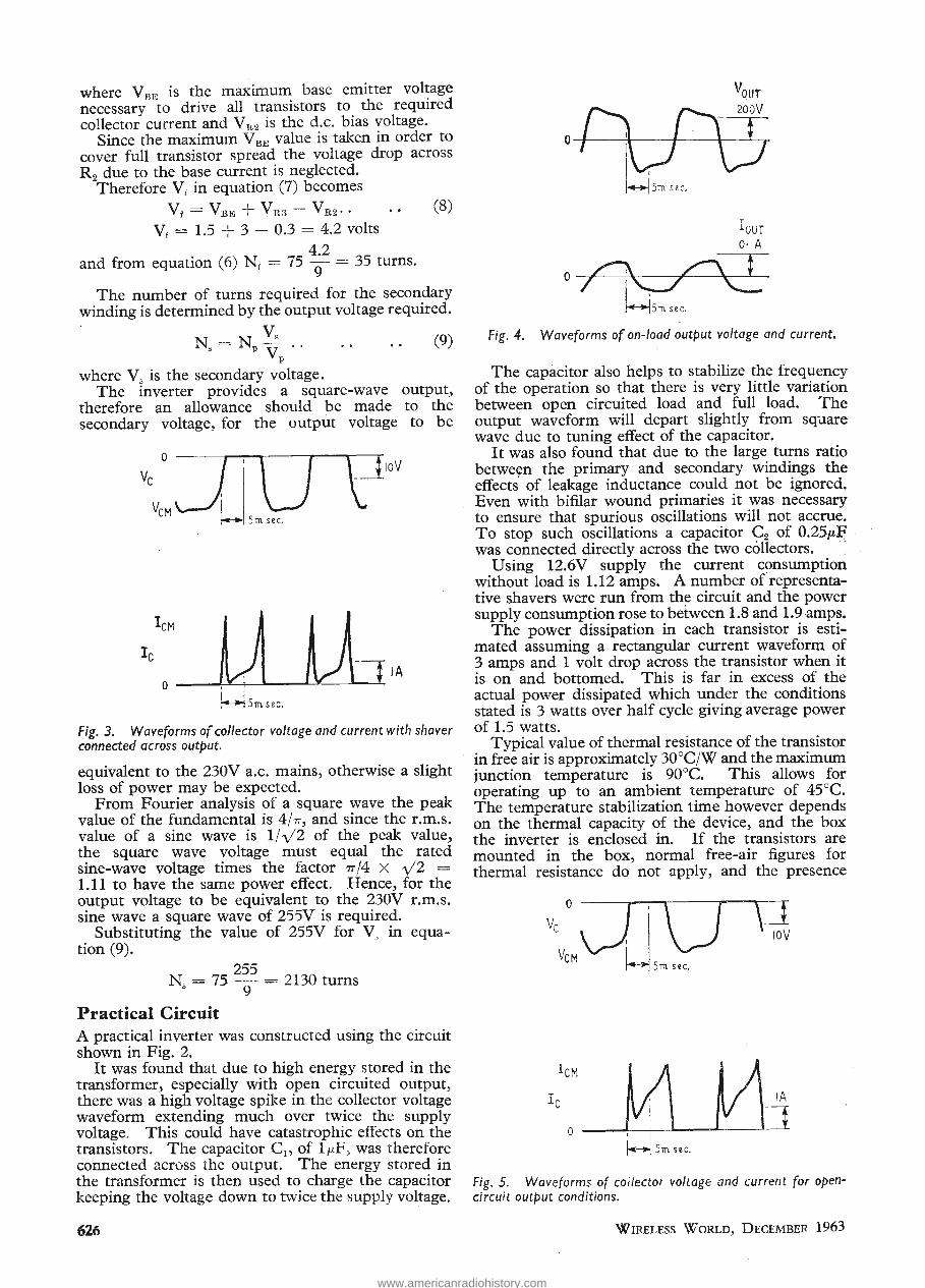
where VnE is the maximum base emitter vol~age necessary to drive all transistors to the reqmred collector current and V Wl is the d.c. bias voltage.
Since the maximum V BE value is taken in order to cover full transistor spread the voltage drop across R9 due to the base current is neglected. ~Therefore V; in equation (7) becomes
v~ = VnE + vR3- vR2·. (8)
vf = 1.5 + 3 - 0.3 = 4.2 volts . 42
and from equation (6) N 1 = 75 i- = 35 turns.
The number of turns required for the secondary winding is determined by the output voltage required.
N" = Nv ~ . . (9) p
where V" is the secondary voltage. The inverter provides a square-wave output,
therefore an allowance should be made to the secondary voltage, for the output voltage to be
lA
Fig. 3. Waveforms of collector voltage and current with shaver connected across output.
equivalent to the 230V a.c. mains, otherwise a slight loss of power may be expected.
From Fourier analysis of a square wave the peak value of the fundamental is 4/7T, and since the r.m.s. value of a sine wave is 1/ v2 of the peak value, the square wave voltage must equal the · rated sine-wave voltage times the factor 7T/4 X y2 =
1.11 to have the same power effect. Hence, for the output voltage to be equivalent to the 230V r.ni.s. sine wave a square wave of 255V is required.
Substituting the value of 255V for V, in equation (9).
255 N , = 75 - = 2130 turns
0 9
Practical Circuit A practical inverter was constructed using the circuit shown in Fig. 2.
It was found that due to high energy stored in the transformer, especially with open circuited output, there was a high voltage spike in the collector voltage waveform extending much over twice the supply voltage. This could have catastrophic effects on the transistors. The capacitor C~" of 1,.F, was therefore connected across the output. The energy stored in the transformer is then used to charge the capacitor keeping the voltage down to twice the supply voltage.
626
Vour D r-l- zoov
01 iv\3 1-lsm sec.
I our O·IA
0~ Fig. 4. Waveforms of on-load output voltage and current.
The capacitor also helps to stabilize the frequency of the operation so that there is very little variation between open circuited load and full load. The output waveform will depart slightly from square wave due to tuning effect of the capacitor.
It was also found that due to the large turns ratio betwe~n the primary and secondary windings the effects of leakage inductance could not be ignored. Even with bifilar wound primaries it was necessary to ensure that spurious oscillations will not accrue. To stop such oscillations a capacitor C 2 of 0.25~~ was connected directly across the two collectors. . ~
Using 12.6V supply the current consumption without load is 1.12 amps. A number ofrepresentative shavers were run from the circuit and the power supply consumption rose to between 1.8 and I. 9 amps.
The power dissipation in each transistor is estimated assuming a rectangular current waveform of 3 amps and 1 volt drop across the transistor when it is on and bottomed. This is far in excess of the actual power dissipated which under the conditions stated is 3 watts over half cycle giving average power of 1.5 watts.
Typical value of thermal resistance of the transistor in free air is approximately 30°C/W and the maximum junction temperature is 90°C. This allows for operating up to an ambient temperature of 45°C. The temperature stabilization time however depends · on the thermal capacity of the device, and the box the inverter is enclosed in. If the transistors are mounted in the box, normal free-air figures for thermal resistance do not apply, and the presence
\J< IOV
I eM k'\ V\-J 0
~ Smsec.
Fig. 5. Waveforms of collector voltage and current for opencircuit output conditions.
WIRELESS WORLD, DECEMBER 1963
where VBE is the maximum base emitter voltage necessary to drive all transistors to the required collector current and VK2 is the d.c. bias voltage.
Since the maximum VBE value is taken in order to cover full transistor spread the voltage drop across R2 due to the base current is neglected.
Therefore V, in equation (7) becomes
vf = VBB + VE3 — VE2.. .. (8)
Vf = 1.5 + 3 - 0.3 = 4.2 volts
4.2 and from equation (6) Nf = 75 — = 35 turns.
The number of turns required for the secondary winding is determined by the output voltage required.
N, = NP^ (9) VP
where V, is the secondary voltage. The inverter provides a square-wave output,
therefore an allowance should be made to the secondary voltage, for the output voltage to be
Fig. 3. Waveforms of collector voltage and current with shaver connected across output.
equivalent to the 230V a.c. mains, otherwise a slight loss of power may be expected.
From Fourier analysis of a square wave the peak value of the fundamental is 4/77, and since the r.m.s. value of a sine wave is 1/V2 of the peak value, the square wave voltage must equal the rated sine-wave voltage times the factor 77/4 x \/2 = 1.11 to have the same power effect. Hence, for the output voltage to be equivalent to the 230V r.m.s. sine wave a square wave of 255V is required.
Substituting the value of 255V for V, in equa- tion (9).
255 Ns = 75 - = 2130 turns
y
Practical Circuit
A practical inverter was constructed using the circuit shown in Fig. 2.
It was found that due to high energy stored in the transformer, especially with open circuited output, there was a high voltage spike in the collector voltage waveform extending much over twice the supply voltage. This could have catastrophic effects on the transistors. The capacitor Q, of 1 /'.F, was therefore connected across the output. The energy stored in the transformer is then used to charge the capacitor keeping the voltage down to twice the supply voltage.
Fig. 4. Waveforms of on-load output voltage and current.
The capacitor also helps to stabilize the frequency of the operation so that there is very little variation between open circuited load and full load. The output waveform will depart slightly from square wave due to tuning effect of the capacitor.
It was also found that due to the large turns ratio between the primary and secondary windings the effects of leakage inductance could not be ignored. Even with bifilar wound primaries it was necessary to ensure that spurious oscillations will not accrue. To stop such oscillations a capacitor Ca of 0.25/iF was connected directly across the two collectors.
Using 12.6V supply the current consumption without load is 1.12 amps. A number of representa- tive shavers were run from the circuit and the power supply consumption rose to between 1.8 and 1.9 amps.
The power dissipation in each transistor is esti- mated assuming a rectangular current waveform of 3 amps and 1 volt drop across the transistor when it is on and bottomed. This is far in excess of the actual power dissipated which under the conditions stated is 3 watts over half cycle giving average power of 1.5 watts.
Typical value of thermal resistance of the transistor in free air is approximately 30oC/W and the maximum junction temperature is 90oC. This allows for operating up to an ambient temperature of 45 0C. The temperature stabilization time however depends on the thermal capacity of the device, and the box the inverter is enclosed in. If the transistors are mounted in the box, normal free-air figures for thermal resistance do not apply, and the presence
!<->( 5ra sec.
Fig. 5. Waveforms of collector voltage and current for open- circuit output conditions.
626 Wireless World, December 1963
www.americanradiohistory.com

Transformer Details
Core lin stack of Linton and Hirst, Pattern No. 12A, 0.020in Lamcor 3, Silicon iron laminations; Joseph Sankey, Pattern No. 102, 42 quality; or M.E.A. Pattern No. 12A (I.S.C.O. 403) Silicor 17, or equivalent.
Bobbin Supplied by Armand Taylor Ltd., Pitsea, Essex.
Primary winding NP1 = NP2 = 75 turns . each of · 22 s.w.g. Lewmex copper wire (bifilar wound).
Secondary N 8 , 2130 turns of 36 s. w.g. winding Lewmex copper wire. Feedback N ,1 = N12, 35 turns each of winding 34 s.w.g. Lewmex copper wire.
Wound in the order given above with 0.003in paper insulation between the layers of the primary winding, O.OOlin paper insulation between the layers of the secondary winding and 0.0075in Scotch Tape insulation between the windings.
of other heat sources may increase the ambient temperature inside the box considerably above the assumed value of 45°C. Therefore the transistors should be mounted on the outside of the box and insulated with mica or p.v.c. washers if the box is made of metal in which case sufficient cooling would be provided.
If a plastic box is used with transistors mounted on the outside, the operation of the inverter up to 15 minutes can be allowed at an ambient temperature of 45°C. This may be marginal in some cases so that some form of heat sink is desirable to allow for ;afety. One method is to use a flat piece of
aluminium 3 X 3 X -h in per transistor which has a thermal resistance of approximately 10°C/W. Since the junction temperature rise above mounting base of the transistor is 2°C/W, the maximum ambient temperature which could be allowed is
TamL = Tiunct- P(Oj-mo + Oh) = 90 - 1.5(2 + 10) = 72°C,
which is more than adequate. The metal plate could be suitably folded to reduce size, alternatively a commercially available finned heat sink could be used.
Further data on heat sink design including some of the convenient types is given in references 4, 5 and 6.
The waveforms of the collector voltage and current are shown in Fig. 3, and the waveforms of the output voltage and current are shown in Fig. 4. These waveforms are for normal operation with the shaver connected across the output.
The waveforms of the collector voltage and current for open-circuit output condition are shown in Fig. 5.
REFERENCES 1. W. L. Stephenson, L. P. Morgan and T. H. Brown
" The Design of Transistor Push-pull D.C. Converters", Electronic Engineering, Vol. 31, No. 380, October 1959, pp. 585 to 589.
2. J. R. Nowicki "Improved High Power D.C. Convertors," Electronic Engineering, Vol. 33, No. 404, October, 1961, pp. 637 to 641.
3. J. R. Nowicki" A D.C. Inverter with C.R. Timing," Electronic Engineering, Vol. 34, No. 413, July 1962, pp. 464 to 468 .
. 4. 0. J. Edwards, "Heat Sink Design" Mullard Technical Communications, Vol. 3, No. 29, March 1958, pp. 258-264.
5. J. H. Tuley, "Design of Cooling Fins for Silicon Power Rectifiers," Mullard Technical Communications, Vol. 5, No. 44, June 1960, pp. 118-130.
6. R. Greenburg, "Factors Influencing Selection of Commercial Power Transistor Heat Sinks." Solid State Design, Vol. 3, No.7, July 1962, pp. 25-31.
H. F. PREDICTIONS- DECEMBER
l:ll I :II o: .! II:, 1:1<:'~ l!lltl :r!l m 1:1.: :u mel :rmu 1:(11~1 -~~~ r--r-
130
- ":'\. 20 15
- -__ __::, 10
,- ____:, .---- /. 8 ,.._ '
. ~· / \. - ·- ·-
·-· 6 \ !-'
1,·' 5 4
' ./ 4 8 12 16 20 0 0 4 8 12 16 20 0 0 4 8 12 16 20 63 \
I G.M.T. G.M.T.
The high daytime MUFs, characteristic of winter conditions on routes largely in the northern hemisphere, are reappearing. It is interesting to note that on southerly circuits to Africa and South America the highest frequencies in the h.f. band will be of use again, even though the sunspot cycle is close to its minimum.
The prediction curves show the median standard MUF, optimum traffic frequency and the lowest usable high frequency (LUF) for reception in this country. Unlike the MUF, the LUF is closely dependent upon such factors as transmitter power, aerials, local noise level and the type of modulation; it should generally be regarded with more diffidence than the MUF. The LUF curves shown are those drawn by Cable and
WIRELESS WORLD, DECEMBER 1963
E
G.M.T. G.M.T.
MEDIAN STANDARD MUF
·--·---··· OPTIMUM TRAFFIC FREQUENCY' -·-·-·-· LOWEST USABLE HF
Wireless, Ltd., for commercial telegraphy and they serve to give some idea of the period of the day for which communication can be expected.
The large sunspot observed during September reappeared on 20th October as the sun rotated, but its area had declined somewhat. Dellinger-type fade-outs were experienced between 18th and 22nd October, and a further fade-out on the 28th was followed by a severe ionosphere storm on the 30th.
627
Transformer Details
Core .. .. lin stack of Linton and Hirst, Pattern No. 12A, 0.020in Lamcor 3, Silicon iron laminations; Joseph Sankey, Pattern No. 102, 42 quality; or M.E.A. Pattern No. 12A (I.S.C.O. 403) Silicor 17, or equivalent.
Bobbin .. Supplied by Armand Taylor Ltd., Pitsea, Essex.
Primary winding Npl = Np2 = 75 turns each of 22 s.w.g. Lewmex copper wire (bifilar wound).
Secondary N85 2130 turns of 36 s.w.g. winding .. Lewmex copper wire. Feedback N^ = Nf2, 35 turns each of winding .. 34 s.w.g. Lewmex copper wire.
Wound in the order given above with 0.003in paper insulation between the layers of the primary winding, O.OOlin paper insulation between the layers of the secondary winding and 0.0075in Scotch Tape insulation between the windings.
of other heat sources may increase the ambient temperature inside the box considerably above the assumed value of 450C. Therefore the transistors should be mounted on the outside of the box and insulated with mica or p.v.c. washers if the box is made of metal in which case sufficient cooling would be provided.
If a plastic box is used with transistors mounted on the outside, the operation of the inverter up to 15 minutes can be allowed at an ambient temperature of 450C. This may be marginal in some cases so that some form of heat sink is desirable to allow for safety. One method is to use a flat piece of
aluminium 3 X 3 X ^ in per transistor which has a thermal resistance of approximately 10oC/W. Since the junction temperature rise above mounting base of the transistor is 20C/W, the maximum ambient temperature which could be allowed is
Tamb = Tiur>cl — P(^-mD + 9h) = 90 - 1.5(2 + 10) = 720C,
which is more than adequate. The metal plate could be suitably folded to reduce size, alternatively a commercially available finned heat sink could be used.
Further data on heat sink design including some of the convenient types is given in references 4,5 and 6.
The waveforms of the collector voltage and current are shown in Fig. 3, and the waveforms of the output voltage and current are shown in Fig. 4. These waveforms are for normal operation with the shaver connected across the output.
The waveforms of the collector voltage and current for open-circuit output condition are shown in Fig. 5.
REFERENCES
1. W. L. Stephenson, L. P. Morgan and T. H. Brown " The Design of Transistor Push-pull D.C. Converters", Electronic Engineering, Vol. 31, No. 380, October 1959, pp. 585 to 589.
2. J. R. Nowicki " Improved High Power D.C. Converters," Electronic Engineering, Vol. 33, No. 404, October, 1961, pp. 637 to 641.
3. J. R. Nowicki " A D.C. Inverter with C.R. Timing," Electronic Engineering, Vol. 34, No. 413, July 1962, pp. 464 to 468.
4. O. J. Edwards, " Heat Sink Design" Mullard Technical Communications, Vol. 3, No. 29, March 1958, pp. 258-264.
5. J. H. Tuley, " Design of Cooling Fins for Silicon Power Rectifiers," Mullard Technical Communications, Vol. 5, No. 44, June 1960, pp. 118-130.
6. R. Greenburg, " Factors Influencing Selection of Commercial Power Transistor Heat Sinks." Solid State Design, Vol. 3, No. 7, July 1962, pp. 25-31.
H. F. PREDICTIONS - DECEMBER
WITH AURORAL CORRECTION
20 0 0 12 16 20 0 0 16 20 0 0
The high daytime MUFs, characteristic of winter conditions on routes largely in the northern hemisphere, are reappearing. It is interesting to note that on southerly circuits to Africa and South America the highest frequencies in the hi. band will be of use again, even though the sunspot cycle is close to its minimum.
The prediction curves show the median standard MUF, optimum traffic frequency and the lowest usable high frequency (LUF) for reception in this country. Unlike the MUF, the LUF is closely dependent upon such factors as transmitter power, aerials, local noise level and the type of modulation; it should generally be regarded with more diffidence than the MUF. The LUF curves shown are those drawn by Cable and
■ MEDIAN STANDARD MUF — OPTIMUM TRAFFIC FREQUENCY ' LOWEST USABLE HF
Wireless, Ltd., for commercial telegraphy and they serve to give some idea of the period of the day for which communication can be expected.
The large sunspot observed during September re- appeared on 20th October as the sun rotated, but its area had declined somewhat. Dellinger-type fade-outs were experienced between 18th and 22nd October, and a further fade-out on the 28th was followed by a severe ionosphere storm on the 30th.
Wireless World, December 1963
E
www.americanradiohistory.com

lJNBIASED
Bats in the Belfry
ON the Post Office stand at the recent Radio Communications Exhibition held in London we were invited to measure the frequency range of our hearing. There was a chart on the wall with a graph on which average frequency response was plotted against age.
Although I found that I could hear frequencies rather above the average for my age, I was made to realize that a lot of the upper musical frequencies reproduced by my set* were just wasted on me.
I got a bit of a shock myself on looking at my frequency reading because as a boy my hearing was exceptionally good especially in the upper register. It so happened that the house where my family lived at one time was quite close to a church, and I found I was being kept awake at night by high-pitched squeaking noises. The family doctor was eventually called in.
In those days a G .P., especially one practising in the country, was a man who had to rely largely on his own resources, as specialists were not so easily within call as nowadays. He soon gave the rather unexpected diagnosis of my complaint as " bats in the belfry."
He was not, however, making what nowadays would I suppose be called a psychosomatic diagnosis, meaning that I was " hearing things " due to some mental disturbance. He merely meant that my hearing in the upper , register was so acute that I was being kept awake at night by the highpitched squeals of the bats from the neighbouring church tower.
* According to the sales literature?-Ed.
Readers' Queries
AT the Radio Communications Exhibition I was interested to see that at the W.W. stand on which were exhibited test instruments described in recent issues, there was a member of the editorial staff to answer readers' queries about these instruments.
I decided to do what I did at Radiolympia 33 years ago and reported in the issue dated Oct. 1st, 1930, namely ensconce myself in a safe place where I could listen to the questions of the readers and hear the replies of the presiding Solomon. In 1930, as I then recorded, there was a clamorous Caledonian asking a
question about oscillating crystals (we call them transistors nowadays) under the impression that they would be
628
By "FREE GRID"
inexpensive to run; he little knew how accurate his impression would
turn out to be. I found 1963 a great contrast to
1930. The W. W. technical expert of today seemed to be far better informed, but so were his questioners. He didn't seem to · be beset so much by what I would call damn fool questions of the unanswerable type as "Why won't my set work?" ·
This latter question cropped up so often when I was listening in 1930, and the technical expert of those distant days didn't seem to have a clue, to use the modern jargon. Indeed the answer to this sort of question always seemed to be handled better by the manager of the stand, whose answer was almost invariably, "You should rewire it." This was very sound advice, as most of the troubles of those days used to be caused by dry soldered joints, and obviously rewiring the set might cure these.
Altogether I spent a very pleasant evening in the vicinity of the W. W.
stand. I only wished I had possessed a pocket tape-recorder. I ought to add that neither in 1930 nor 1963 did I ask any questions myself.
Photography's Debt
NO doubt many of you were interested in the note in the November issue on a new camera in which electronics play such an important part.
We have, in recent years, all got used to hearing or reading about the popularly called automatic camera in which a photocell is employed to control the aperture of the lens according to the ambient light. In some cameras the photocell varies the speed of the shutter instead of the aperture, while in others both arerture and shutter speed are controlled. Although such cameras have only become available to us in qu.i.te recent years, they are by no means new as I described one nearly thirt·1 years ago in the issue of July 20th, 1934.
I think the greatest advantage of the new camera is that the photocell adjusts the shutter speed not only when using daylight and artificial light of the type provided by ordinary Toom lighting or photofloods, but also when using a flash gun.
This camera still cannot claim llgo
be called panautomatic however, and there is still some work for us electronics people to do in providing an automatic rangefinder in place of the manually operated one built into it.
Of course, ~e ~auld do it straight away by eqUippmg the camera with radar but this would necessitate a pantechnicon to carry the necessary apparatus.
Cymric Correction
I AM sorry to say that when I mentioned in the October issue that the longest word in Welsh had 52 letters I caused offence to certain of my Cymric readers. I was, of course referring to the well-known Welsh
place ~~ich, for the sake of brevity, the Bntlsh Post Office calls Llanfair P.G.
It apparently has 60 not 52 letters but even this is an abbreviatio~ because the final three syllables which most of us know, namely gogogoch
were originally gerllaw yr ogof goch:
These were contracted to ger yr
ogo'goch, then to g' ogo' goch and finally to gogogoch. -
It is always dangerous to dabble in a language with which you are not thoroughly familiar, as we learned
from Jerome K . Jerome's " Three men on the bummel." One of the three men entered a German shop to buy a cushion and mistakenly asked the girl in the shop for a kuss instead of a kissen. I have always found German girls to be of a kindly nature and so it did not altogether surprise me that he got both. It reminds me of an occasion forty years ago when I entered - a shop in Hamburg's famous Reeperbahn . . . but maybe you had better wait to read about that in my memoirs.
Gilberti ana
ALL readers of W.W., except those who only carry it about as a status symbol, will have heard of Dr. William Gilbert, of Colchester, who in the year 1600 published his famous work " De Magnete."
Apart from his purely magnetic studies, Dr. Gilbert did a lot of work in the electrical field, and, according to certain American history books, he demonstrated electrostatic attraction by rubbing his pen on Queen Elizabeth I's silk stockings.
I can forgive the Americans their little fantasies of history but I cannot extend the same amused tolerance when I find far worse errors put on record by writers of our own nationality, more especially when they occur in articles intended for children. None of us likes to see children misled, and I was, therefore, truly shocked when I found in the
WIRELESS WORLD, DECEMBER 1963
UNBIASED
Bats in the Belfry }
ON the Post Office stand at the recent t Radio Communications Exhibition held in London we were invited to J measure the frequency range of our t hearing. There was a chart on the wall with a graph on which average frequency response was plotted against age. <
Although I found that I could hear frequencies rather above the average for my age, I was made to realize 1
that a lot of the upper musical fre- 1
quencies reproduced by my set* were just wasted on me.
I got a bit of a shock myself on looking at my frequency reading because as a boy my hearing was exceptionally good especially in the upper register. It so happened that the house where my family lived at one time was quite close to a church, and I found I was being kept awake at night by high-pitched squeaking noises. The family doctor was eventually called in.
In those days a G.P., especially one practising in the country, was a man who had to rely largely on his own resources, as specialists were not so easily within call as nowadays. He soon gave the rather unexpected diagnosis of my complaint as " bats in the belfry." .
He was not, however, making what nowadays would I suppose be called a psychosomatic diagnosis, meaning that I was " hearing things " due to some mental disturbance. He merely meant that my hearing in the upper register was so acute that I was being kept awake at night by the high- pitched squeals of the bats from the neighbouring church tower.
* According to the sales literature?—Ed.
Readers' Queries
AT the Radio Communications Ex- hibition I was interested to see that at the W.W. stand on which were exhibited test instruments described in recent issues, there was a member of the editorial staff to answer readers' queries about these instru- ments.
I decided to do what I did at Radiolympia 33 years ago and reported in the issue dated Oct. 1st, 1930, namely ensconce myself in a safe place where I could listen to the questions of the readers and hear the replies of the presiding Solomon. In 1930, as I then recorded, there was a clamorous Caledonian asking a question about oscillating crystals (we call them transistors nowadays) under the impression that they would be
By "FREE GRID'
inexpensive to run; he little knew how accurate his impression would turn out to be.
I found 1963 a great contrast to 1930. The W.W. technical expert of today seemed to be far better in- formed, but so were his questioners. He didn't seem to be beset so much by what I would call damn fool ques- tions of the unanswerable ^type as " Why won't my set work? "
This latter question cropped up so often when I was listening in 1930, and the technical expert of those dis- tant days didn't seem to have a clue, to use the modern jargon. Indeed the answer to this sort of question always seemed to be handled better by the manager of the stand, whose answer was almost invariably, "You should rewire it." This was very sound advice, as most of the troubles of those days used to be caused by dry soldered joints, and obviously rewir- ing the set might cure these.
Altogether I spent a very pleasant evening in the vicinity of the W.W. stand. I only wished 1 had possessed a pocket tape-recorder. I ought to add that neither in 1930 nor 1963 did I ask any questions myself.
Photography's Debt
NO doubt many of you were interested in the note in the Novem- ber issue on a new camera in which electronics play such an important part.
We have, in recent years, all got used to hearing or reading about the popularly called automatic camera in which a photocell is employed to control the aperture of the lens according to the ambient light. In some cameras the photocell varies the speed of the shutter instead of the aperture, while in others both aperture and shutter speed are con- trolled. Although such cameras have only become available to us in quite recent years, they are by no means new as I described one nearly thirty years ago in the issue of July 20th, 1934- j f
I think the greatest advantage of the new camera is that the photocell adjusts the shutter speed not only when using daylight and artificial light of the type provided by ordinary room lighting or photo- fioods, but also when using a flash gun. .
This camera still cannot claim to be called panautomatic however, and there is still some work for us elec- tronics people to do in providing an automatic rangefinder in place of the manually operated one built into it.
Of course, we could do it straight away by equipping the camera with radar but this would necessitate a pantechnicon to carry the necessary apparatus.
Cymric Correction
I AM sorry to say that when I men- tioned in the October issue that the longest word in Welsh had 52 letters, I caused offence to certain of my Cymric readers. I was, of course, referring to the well-known Welsh place which, for the sake of brevity, the British Post Office calls Llanfair P.O. ^ ,
It apparently has 60 not 52 letters, but even this is an abbreviation because the final three syllables which most of us know, namely gogogoch, were originally gerllaw yr ogof goch. These were contracted to ger yr ogo'goch, then to g' ogo' goch and finally to gogogoch.
It is always dangerous to dabble in a language with which you are not thoroughly familiar, as we learned from Jerome K. Jerome's "Three men on the bummel." One of the three men entered a German shop to buy a cushion and mistakenly asked the girl in the shop for a kuss instead of a kissen. I have always found German girls to be of a kindly nature and so it did not altogether surprise me that he got both. It reminds me of an occasion forty years ago when I entered a shop in Hamburg s famous Reeperbahn . . . but maybe you had better wait to read about that in my memoirs.
Gilber liana
ALL readers of W.W., except those who only carry it about as a status symbol, will have heard of Dr. William Gilbert, of Colchester, who in the year 1600 published his famous work " De Magnete."
Apart from his purely magnetic studies, Dr. Gilbert did a lot of work in the electrical field, and, according to certain American history books, he demonstrated electrostatic attraction by rubbing his pen on Queen Eliza- beth I's silk stockings. .
I can forgive the Americans their little fantasies of history but I can- not extend the same amused toler- ance when I find far worse errors put on record by writers of our own nationality, more especially when they occur in articles intended tor children. None of us likes to see children misled, and I was, therefore, truly shocked when I found in tne
Wireless World, December 1963
www.americanradiohistory.com

children's corner of a newspaper published in Dr. Gilbert's own county of Essex, a veritable mass of misinformation about him. The writer is a woman, and so I shall spare her feelings by not giving the name of the newspaper.
She tells her innocent little readers quite rightly that Dr. Gilbert was born in Colchester in 1540, and was one of Queen Elizabeth's medical advisers but after that she seems to go off the rails completely. She just says that "Gilbert was one of the earliest men to realize that there was such a thing as electricity." This seems a very startling statement, more especially in view of the fact that Gilbert's only knowledge of it could have been the phenomena associated with the rubbing of amber, etc., and this had been noted by Thales over two thousand years earlier, as the writer herself mentions later in her article.
She also tells the children that, having realized " there was such a thing as electricity . . . he [Gilbert] had to think of a name for it." She informs her wondering little readers, by now all agog for more knowledge about the man who discovered the stuff that works the " telly," that he was the first to use the word " electricity," thus ignoring the fact that the O.E.D. is unable to find any earlier use than 1647, which was 44 years after Gilbert died.
The writer makes what is perhaps her most startling error in a matter which is neither technical nor historical but simply of elementary etymology. After telling her youthful readers quite correctly all about Gilbert's experiments with amber, she drops a heavy brick by saying " he used its Latin name 'elektron'."
Ultrasonic Cleaning
AN interesting article on cleaning by means of ultrasonic waves appeared in the November issue of our sister journal Industrial Electronics. I was sorry to see, however, that the writer gave me no information about how I could wash my smalls by this method but of course, it is an industrial journal. There certainly was one ultrasonic clothes washer of German manufacture in this country a few years ago*. It was quite a simple device which the user stuck into any old tub full of clothes, but I have heard nothing of it lately.
I gathered from the article i.hat .i.f th.! power and frequency of an ultra~ sonic cleaner are incorrectly adjusted, instead of removing the dirt from the article it could remove the article from the dirt!
Somehow or other the writer left me with the impression that we needn't think of scrapping our existing washing machines just yet, although I am sure that eventually the ultrasonic type will reign supreme.
* And also one operating from a.c. mains at 50, possibly lOOc/s-Ed
WIRELESS WORLD, DECEMBER 1963
FIRST IN THE FIELD
WITH THE MANUFACTURE
OF SIGNAL LAMPS IN 1925
Blackpool's famous illuminations, pictured above, are well known throughout the country and attract hundreds of people each year.
Although they are not on the same scale Bulgin Signal Lamps are equally famous and attract just as much attention in their own field. The lenses can be supplied in either Plastic, working up to 140°C, or Glass and both types are available in a choice of five sparkling transparent or diffused · colours, Red, Amber, Green, Blue and Clear, which give a brilliant 180° signal that immediately catches the eye.
2;700 VARIETIES Lamp holder types include
M.E.S., M.B.C., L.E.S., S.B.C., etc., etc., and various fixing means are employed. Connection can be to either Solder Tags, Screw Terminals or leads and there are models to suit both low voltage and Mains applications.
For full details, dimensions and illustrations of our complete range, write for leaflet 1502/C to:-
The Publications Section,
A. I". BULGIN 81: CO. LTD. BYE- PASS ROAD, BARKING; ESSEX. Telephone: RIPpleway 5588 (12 lines)
3WW- 121 FOR FURTHER DETAILS. 629
FiRST IN THE FIELD
WITH THE MANUFACTURE
OF SIGNAL ^AMPS
IN 1925
children's corner of a newspaper published in Dr. Gilbert's own county of Essex, a veritable mass of misinformation about him. The writer is a woman, and so I shall spare her fee ngs by not giving the name of the newspaper
She tells her innocent little readers quite i" ihtly that Dr. Gilbert was born in Colchester in 1540, and was one of Queen Elizabeth's medical ad- visers but after that she seems to go off the rails completely. Sbe just ays that "Gilbert was one of the earliest men to realize that her was such a thing as electria ;y." This seems a very startling statement, more especi- ally in view of the fact thai Gilbert's only knowledge of 1. could have been the phenomena associated wi i the rubbing of amber, etc., and this had been noted by Thales over two tl o u- sand years earlier, as the writer her- self mentions later in her article.
She also tells the ch iren that, having realized "there was such a thing as electricity ... he [Gilbertj had to think of a name for it. ^he informs her wondering little rei rs, by now all agog for more knowledge about the man who discovered the stuff that works the "telly," that he was the first to use the wor " elec- tricity," thus ignoriu', the fact that the O.E.D. is unable ft find any earlier use than 1647, which was 44 years after Gilbert died.
The writer makes what is perhaps her most startling errOi. . i a matter which is neither techn al nor histori- cal but simply of elementary etyn logy. After telling her youthful readers quite correctly all about Gil- bert's experiments w h amber, ; be drops a heavy brick by s0; l "he used its Latin name ' elektron'."
Ultrasonic Cleaning
AN interesting article on cleaning by means of ultrasor waves ap- peared in the November issue of (pur sister journal Indust al Ele> ronics. I was lorry to see, however, that the writer gave me no information about how I could wash my smalls by this method but of course, it is an idus- trial journal. There certainly was one ultrasonic clothes washer of German manufacture in this country a few years ago*. It was quite a simple device which tne user st .:k into any old tub full of :lothes, but I have heard nothii ; of it lately.
I gathered from the article tl at If the power and frequency of a altca- soni cleaner are incorrectly adjusted, instead of removing the irt from the article it could remove the article from the dirt!
Somehow or other the writer left me with the impression that we needn't think of scrapping our exist- ing washing machines just yet, although I am sure that? eventually the ultrasonic type will reign supreme.
* And also one 50, possibly 100c/
c'ITlcs.
BULGIN
*>*.*■
* * f
• .
Blackpool's famous illumina- tions, pictured above, are well known throughout the country and attract hundreds of people each year.
1 Although they are not on the same scale Bulgin Signal Lamps are equally famous and attract just as much attention in their c m field. The lenses can be supplied in either Plastic, working up to 140oC, or Glass and both types are available in a choice of five sparkling transparent or diffused colours. Red, Amber, Gre lue and Clear, wh. Ji g ve a brilliant 180° signal that immediately catches the eye.
Lamp holder types include M.E.S., M.B.C., L.E.S., S.B.C., etc., etc., and various fixing means are employed. Connection can be to either Solder Tags, Screw Terminals or leads and there are models to suit both low voltage and Mains applications.
For full details, dimensions and illustrations of r range, write for leaflet 1S02/C to:
The Publications Section,
is F. BULGIN & CO. LTD. BYE-PASS ROAD, BVS ,ING> ES
1^EX;
Telephone: RIPpleway 5588 (12 lines)
www.americanradiohistory.com

DECEMBER MEETINGS
Tickets are required for some meetings : readers are advised, therefore, to communicate with the secretary
of the society concerned
LONDON 2nd. I.E.E.-" Atmospheric radio
noise as a problem in radio communications" by F. Horner at 5.30 at Savoy Place, W.C.2.
2nd. Brit.I.R.E. & I.E.E.-Symposium on " Analogue circuit techniques using transistors " at 6.0 at the London School of Hygiene and Tropical Medicine, Keppel Street, W.C.l.
4th. I.E.E.-Colloquium on "Connections in electronic circuits " at 2.30 at Savoy Place, W.C.2.
4th. Brit.I.R.E.-Syml'osium on "New developments in television cameras and zoom lenses " at 6.0 at the London School of Hygiene, Keppel Street, W.C.l.
5th. Instn. of Production Engrs." Printed circuits as aids to production " by E. W. Huggins at 7.0 at the Royal Aeronautical Society, 4 Hamilton Place, W.I.
6th. Television Society.-" Colour captions using monochrome equipment" by M. Cox at 7.0 at I.T.A., 70 Brompton Road, S.W.3.
9th. I.E.E.-Discussion on "Measurements at very low frequencies with particular reference to noise" at 5.30 at Savoy Place, W.C.2.
11th. I.E.E.-" The impact of modern ionosphere research on communications" by G. Millington at 5.30 at Savoy Place, W.C.2.
12th. Brit.I.R.E. & I.E.E.-Discussion on "The brain" at 10.30 at the Department of Physiology, University College, Gower . Street, W.l.
12th. Institution of Electronics." Instrumentation in rockets and satellites" by J. Bowles at 7.0 at the London School of Hygiene and Tropical Medicine, Keppel Street, W.C.l.
12th. Radar & Electronics Association. -"Teaching by electronics" by Paul Thompson at 7.0 at the Royal Society of Arts, John Adam Street, W.C.2.
12th. Television Society.-Discussion on " The proposed u.h.f. television service" at 7.0 at I.T.A., 70 Brompton Road, S.W.3.
13th. B.S.R.A.-" Post-war pickup development" by S. Kelly at 7.15 at the Royal Society of Arts, John Adam Street, W.C.2.
16th. I.E.E.-" Ceramic sealing techniques applied to electron tubes apd semicond1,1ctor devices" by W. F. Gibbons at 5.30 at Savoy Place, W.C.2.
16th. I.E.E. Graduates.-" Cemmunications and radio " by Sir Albert Mumford (President) at 6.30 at Savoy Place, W.C.2.
ABERDEEN 11th. I.E.E.-" Some aspects of the
use of computers· in process-control applications" by J, F. Roth at 6.0 at Robert Gordon's Technical College.
BIRMINGHAM 2nd. I.E.E. & Instn. of P.O. Electl.
Engrs.-" Global communications " by R. J. Halsey at 7.0 at the Chamber of Commerce Building, Harborne Road.
18th. Television Society.-" Sound off-vision on " by Al Read at 7.0 at the College of Advanced Technology, Gosta Green.
BRISTOL 4th. Brit.I:_.R.E.-" The ionosphere
-international geophysical year results " by G. M. Brown at 6.30 at the University Engineering Lecture Rooms.
CAMBRIDGE 12th. I.E.E.-" Masers" by Dr. K.
Hoselitz at 8.0 at the . Engineering Laboratories, Trumpington Street.
CARDIFF 4th. Brit.I.R.E.-" Recent develop
ments in radio astronomy" by ]. Heywood at 6.30 at the College of Advanced Technology.
CATTERICK lOth. I.E.E.-" Data transmission
systems " by D. A. A. Lamb at 6.30 at the School of Signals, Catterick Camp.
CHELTENHAM 6th. Brit.I.R.E.-" Methods of dis
tinguishing sea radar targets from clutter" by A. Harrison at 7.0 at the North Gloucestershire Technical College.
CREWE 2nd. I.E.E.-"The colour performance
of the Secam colour television system " by G. B. Townsend at 7.0 at the Crewe Arms Hotel.
DUNDEE 12th. I.E.E.-" Some aspects of the
use of computers in process-control applications" by ]. F. Roth at 6.0 at the Electrical Engineering Department, Queen's College.
EDINBURGH 2nd I.E.E.-" The training of high
grade technician engineers " by A. H. Morton at 7.0 at the Carlton Hotel, North Bridge.
lOth I.E.E. & Brit.I.R.E.-" Noise analysis techniques" by F. D. Boardman at 7.0 at the Carlton Hotel, North Bridge.
11th. Brit.I.R.E. - "Electronic timing" by A. McKenzie at 7.0 at the Department of Natural Philosophy, The University, Drummond Street.
GLASGOW 9th. I.E.E. & Brit.I.R.E.-" Noise
analysis techniques" by F. D. Boardman at 6.0 at the Royal College of Science and Technology.
12th. Brit.I.R.E. - "Electronic timing " by A. McKenzie at 7.0 at the Institution of Engineers and Shipbuilders, 39 Elmbank Crescent.
HATFIELD 9th. I.E.E.-" Global communica
tions" by R. ]. Halsey at 7.0 at Hatfield College of Technology. ·
HULL 5th. I.E.E.-" The junction transistor
-its properties and some applications " by B. J. Clarke at 6.30 at the Y.E.B. Office~, Ferensway.
LEICESTER 4th. Brit.I.R.E.-" Medical elec-
tronics" by W. J. Perkins at 6.45 at the University.
lOth. Television Society-"Television in retrospect" by H. J. Barton-Chapple at 7.30 at the Main Hall, Vaughan College, St. Nicolas Street.
LIVERPOOL 18th. Brit.I.R.E.-" Tunnel diodes"
by M. R. McCann at 7.30 at the Walker Art Gallery.
MANCHESTER 4th. I.E.E.-" Electronic switching as
applied to a working telephone exchange" by G. Forshaw at 6.15 at the Reynolds Hall, College of Science and Technology.
5th. Brit.I.R.E.-" Satellites for television communications" by L. F. Mathews at 7.0 at the Reynolds Hall College of Science and Technology. '
NEWCASTLE-UPON-TYNE 2nd. I.E.E.-" Pulse techniques in line
communications" by R. 0. Carter at 6.30 at the Rutherford College of Technology, Northumberland Road.
lith. Brit.I.R.E.-" Optical masers" by Dr. J. H. Sanders at 6.0 at the Institute of Mining and Mechanical Engineers, Westgate Road.
17th. I.E.E.-" The colleges of advanced technology" by Dr. G. N. Patchett at 6.15 at the Rutherford College of Technol9gy, Northumberland Road.
NOTTINGHAM 4th. Instn. of Production Engrs.
" Ultrasonics" by E. W. P. Stroud at 7.0 at the Reform Club, Victoria Street.
PORTSMOUTH 11th. Brit.I.R.E.-" Principles and
practice of data logging" by R. F. Martin at 6.30 at Highbury Technical College, Cosham.
SOUTHAMPTON lOth. I.E.E.-" Recent developments
in electrical transducers" by P. Wood and D. Underwood at 6.30 at the University.
SWANSEA 12th. I.E.E.-" Lasers" by Dr. W. G.
Townsend at 6.15 at College House, University College, Singleton Park.
T(.R(}UAY 5th. I.E.E.-" Masers" by C. R.
Ditchfield at 3.0 at Electricity House, Union Street.
WOLVERHAMPTON Hth. Brit.I.R.E.-" Evolution in
logic control systems" by Dr. J. N. Fletcher at 7.15 at the College of Technology.
WIRELESS WoRLD, DECEMBER 1963
DECEMBER MEETINGS
Tickets are required for some meetings : readers are advised, therefore, to communicate with the secretary of the society concerned
LONDON 2nd. I.E.E.—" Atmospheric radio
noise as a problem in radio communica- tions " by F. Homer at 5.30 at Savoy Place, W.C.2.
2nd. Brit.I.R.E. & I.E.E.—Sympo- sium on "Analogue circuit techniques using transistors" at 6.0 at the Lon- don School of Hygiene and Tropical Medicine, Keppel Street, W.C.I.
4th. I.E.E.—Colloquium on " Con- nections in electronic circuits " at 2.30 at Savoy Place, W.C.2.
4th. Brit.I.R.E.—Symposium on " New developments in television cameras and zoom lenses " at 6.0 at the London School of Hygiene, Keppel Street, W.C.I.
5th. Instn. of Production Engrs.— " Printed circuits as aids to production " by E. W. Huggins at 7.0 at the Royal Aeronautical Society, 4 Hamilton Place, W.l.
6th. Television Society.—" Colour captions using monochrome equipment" by M. Cox at 7.0 at I.T.A., 70 Bromp- ton Road, S.W.3.
9th. I.E.E.—Discussion on "Mea- surements at very low frequencies with particular reference to noise" at 5.30 at Savoy Place, W.C.2.
11th. I.E.E.—"The impact of modern ionosphere research on com- munications " by G. Millington at 5.30 at Savoy Place, W.C.2.
12th. Brit.I.R.E. & I.E.E.—Discus- sion on " The brain " at 10.30 at the Department of Physiology, University College, Gower Street, W.l.
12th. Institution of Electronics.— " Instrumentation in rockets and satel- lites" by J. Bowles at 7.0 at the Lon- don School of Hygiene and Tropical Medicine, Keppel Street, W.C.I.
12th. Radar & Electronics Association. —"Teaching by electronics" by Paul Thompson at 7.0 at the Royal Society of Arts, John Adam Street, W.C.2.
12th. Television Society.—Discus- sion on " The proposed u.h.f. television service" at 7.0 at I.T.A., 70 Brompton Road, S.W.3.
13th. B.S.R.A.—" Post-war pickup development" by S. Kelly at 7.15 at the Royal Society of Arts, John Adam Street, W.C.2.
16th. I.E.E.—" Ceramic sealing tech- niques applied to electron tubes and semiconductor devices " by W. F. Gib- bons at 5.30 at Savoy Place, W.C.2.
16th. I.E.E. Graduates.—" Commu- nications and radio" by Sir Albert Mumford (President) at 6.30 at Savoy Place, W.C.2.
ABERDEEN 11th. I.E.E.—" Some aspects of the
use of computers in process-control applications" by J. F. Roth at 6.0 at Robert Gordon's Technical College.
BIRMINGHAM 2nd. I.E.E. & Instn. of P.O. Electl.
Engrs.—" Global communications " by R. J. Halsey at 7.0 at the Chamber of Commerce Building, Harborne Road.
18th. Television Society.—" Sound off—vision on " by A1 Read at 7.0 at the College of Advanced Technology, Gosta Green.
BRISTOL 4th. Brit.J.R.E.—" The ionosphere
—international geophysical year results " by G. M. Brown at 6.30 at the Univer- sity Engineering Lecture Rooms.
CAMBRIDGE 12th. I.E.E.—" Masers " by Dr. K.
Hoselitz at 8.0 at the Engineering Laboratories, Trumpington Street.
CARDIFF 4th. Brit.I.R.E.—" Recent develop-
ments in radio astronomy" by J. Hey- wood at 6.30 at the College of Advanced Technology.
CATTERICK 10th. I.E.E.—" Data transmission
systems " by D. A. A. Lamb at 6.30 at the School of Signals, Catterick Camp.
CHELTENHAM 6th. Brit.I.R.E.—"Methods of dis-
tinguishing sea radar targets from clut- ter" by A. Harrison at 7.0 at the North Gloucestershire Technical College.
CREWE 2nd. I.E.E.—"The colour performance
of the Secam colour television system" by G. B. Townsend at 7.0 at the Crewe Arms Hotel.
DUNDEE 12th. I.E.E.—" Some aspects of the
use of computers in process-control applications " by J. F. Roth at 6.0 at the Electrical Engineering Department, Queen's College.
EDINBURGH 2nd I.E.E.—"The training of high-
grade technician engineers" by A. H. Morton at 7.0 at the Carlton Hotel, North Bridge.
10th I.E.E. & Brit.I.R.E.—" Noise analysis techniques" by F. D. Board- man at 7.0 at the Carlton Hotel, North Bridge.
11th. Brit.I.R.E. — "Electronic timing " by A. McKenzie at 7.0 at the Department of Natural Philosophy, The University, Drummond Street.
GLASGOW 9th. I.E.E. & Brit.I.R.E.—" Noise
analysis techniques" by F. D. Board- man at 6.0 at the Royal College of Science and Technology.
12th. Brit.I.R.E. — "Electronic timing" by A. McKenzie at 7.0 at the Institution of Engineers and Ship- builders, 39 Elmbank Crescent.
HATFIELD 9th. I.E.E.—" Global communica-
tions " by R. J. Halsey at 7.0 at Hatfield College of Technology.
HULL 5th. I.E.E.—" The junction transistor
—its properties and some applications " by B. J. Clarke at 6.30 at the Y.E.B, Offices, Ferensway.
LEICESTER 4th. Brit.I.R.E.—" Medical elec-
tronics " by W. J. Perkins at 6.45 at the University.
10th. Television Society—"Television in retrospect" by H. J. Barton-Chappie at 7.30 at the Main Hall, Vaughan Col- lege, St. Nicolas Street.
LIVERPOOL 18th. Brit.I.R.E.—"Tunnel diodes"
by M. R. McCann at 7.30 at the Walker Art Gallery.
MANCHESTER 4th. I.E.E.—" Electronic switching as
applied to a working telephone ex- change " by G. Forshaw at 6.15 at the Reynolds Hall, College of Science and Technology.
5th. Brit.LR.E.—" Satellites for tele- vision communications" by L. F. Mathews at 7.0 at the Reynolds Hall, College of Science and Technology.
NEWCASTLE-UPON-TYNE 2nd. I.E.E.—" Pulse techniques in line
communications" by R. O. Carter at 6.30 at the Rutherford College of Tech- nology, Northumberland Road.
11th. Brit.I.R.E.—"Optical masers" by Dr. J. H. Sanders at 6.0 at the Institute of Mining and Mechanical Engineers, Westgate Road.
17th. I.E.E.—" The colleges of advanced technology" by Dr. G. N. Patchett at 6.15 at the Rutherford Col- lege of Technology, Northumberland Road.
NOTTINGHAM 4th. Instn. of Production Engrs.—
" Ultrasonics" by E. W. P. Stroud at 7.0 at the Reform Club, Victoria Street.
PORTSMOUTH 11th. Brit.LR.E.—"Principles and
practice of data logging " by R. F. Mar- tin at 6.30 at Highbury Technical Col- lege, Cosham.
SOUTHAMPTON 10th. I.E.E.—" Recent developments
in electrical transducers" by P. Wood and D. Underwood at 6.30 at the Uni- versity.
SWANSEA 12th. I.E.E.—"Lasers" by Dr. W. G.
Townsend at 6.15 at College House, University College Singleton Park.
TORQUAY 5th. I.E.E.—"Masers" by C. R.
Ditchfield at 3.0 at Electricity House, Union Street.
WOLVERHAMPTON 11th. Brit.I.R.E.—"Evolution in
logic control systems" by Dr. J. N. Fletcher at 7.15 at the College of Tech- nology.
Wireless World, December 1963
www.americanradiohistory.com

m
'i,. m
m r:.r
•i-
;
11 i
:
SB
1 i
at; ■ T Ttlrfi
•- www.americanradiohistory.com