
Intelligent Telemetry for Freight Trains using Wireless Sensor Networks
Reid R. Harrison
Intan Technologies, LLC Los Angeles, California
http://www.intantech.com
Low-Power Integrated Circuits for Advanced Neural Interfaces
Neuroengineering Symposium, University of Illinois at Urbana-Champaign June 20, 2013

Outline
• Biopotential amplifier design
• Wireless cortical recording system (Utah Integrated Neural Interface)
• Electrophysiology recording lab on a chip (Intan Technologies RHD2000)
• Wireless telemetry: locust escape response
• Wireless telemetry: dragonfly in-flight prey capture

From Beckman Institute to Beckman Institute
Computation and Neural Systems program NeuroEngineering IGERT

From Beckman Institute to Beckman Institute
Computation and Neural Systems program NeuroEngineering IGERT
Arnold O. Beckman (1900 – 2004) B.S., Chemical Engineering, University of Illinois at Urbana-Champaign, 1922 M.S., Physical Chemistry, University of Illinois at Urbana-Champaign, 1923 Ph.D., Chemistry, Caltech, 1928 “Arnold O. Beckman developed the first commercially successful electronic pH meter… The innovative features of the pH meter, including an early use of integrated electronic technology, were the basis for subsequent modern instrumentation…”
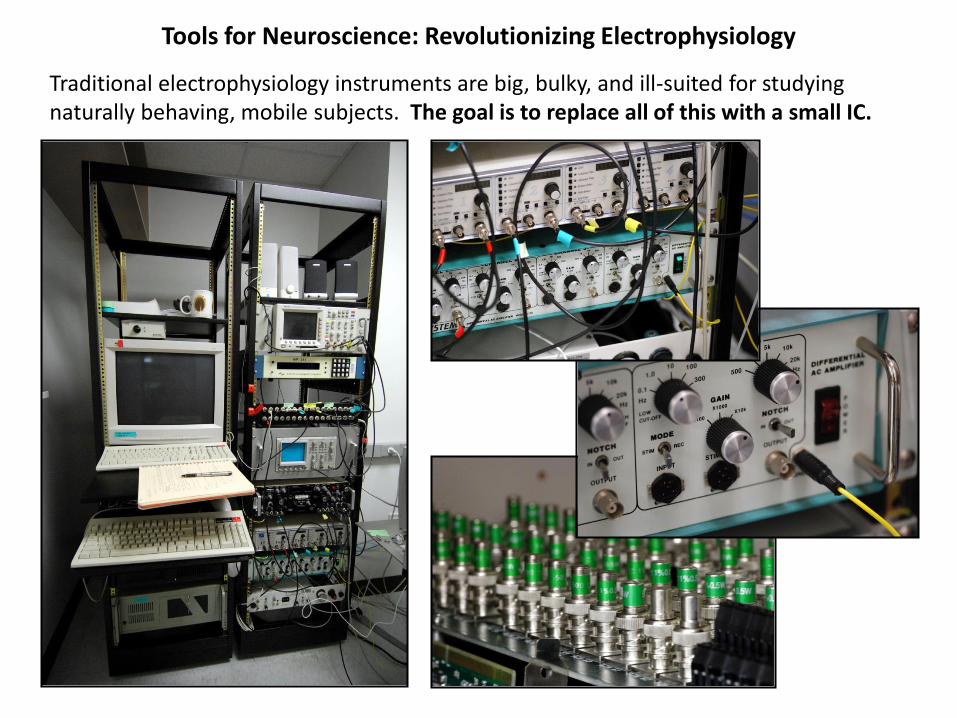
Tools for Neuroscience: Revolutionizing Electrophysiology
Traditional electrophysiology instruments are big, bulky, and ill-suited for studying naturally behaving, mobile subjects. The goal is to replace all of this with a small IC.

Biopotential amplifier requirements
signal frequency si
gnal
am
plitu
de
1 Hz 10 Hz 100 Hz 1 kHz 10 kHz
1 µV
10 µV
100 µV
1 mV
10 mV
neural
spikes
EMG
EMG (internal)
ECG
LFPs
EEG
An integrated front-end amplifier for biopotentials should:
• Amplify signals in the frequency bands of interest;
• Block dc offsets present at the electrode-tissue interface to prevent saturation of the amplifier;
• Have sufficiently low input-referred noise to resolve biological signals in the low microvolt range;
• Have sufficient dynamic range to convey signals in the low millivolt range;
• Have much higher input impedance than the electrode-tissue interface and have negligible dc input current;
• Reject common-mode signals (high CMRR) particularly at 50/60 Hz; reject power supply noise (high PSRR);
• Consume little silicon area, and use few or no off-chip components to minimize size;
• Consume little power, to facilitate wearable or implantable applications.

BW4
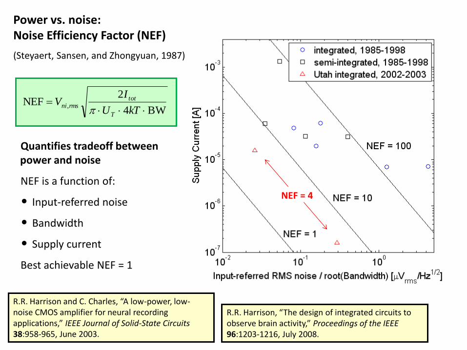
2NEF ,
kTU
IV
T
totrmsni
Quantifies tradeoff between power and noise
NEF is a function of:
• Input-referred noise
• Bandwidth
• Supply current
Best achievable NEF = 1
Power vs. noise: Noise Efficiency Factor (NEF)
(Steyaert, Sansen, and Zhongyuan, 1987)
Problem: integrating many low-noise amplifiers (without cooking cortex!)
At the turn of the century, existing integrated biosignal amplifiers were too noisy and/or
consumed too much power, and many required one or two off-chip components per channel.
Gm R1
in–
in+
FS
FS
C1 C2
MPR
MFS
C2
MPR
MFS
C1
CL
R2
R2
out+
out–
log frequency (Hz)
log
gain
(V
/V)
C1
C2
AM =
fL = 2πRPRC2
1 fH =
2πCLAM
Gm
fz = fH C2
2
C1CL
C2
CL
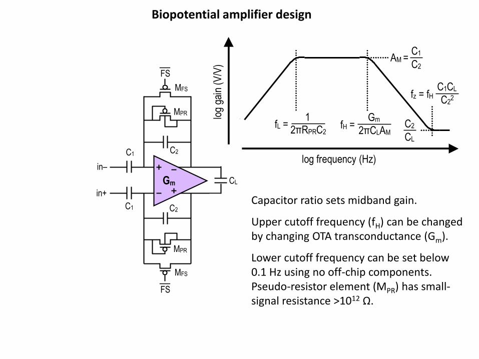
Capacitor ratio sets midband gain.
Upper cutoff frequency (fH) can be changed by changing OTA transconductance (Gm).
Lower cutoff frequency can be set below 0.1 Hz using no off-chip components. Pseudo-resistor element (MPR) has small-signal resistance >1012 Ω.
Biopotential amplifier design

Using drain currents in the 20 nA – 40 μA range, CMOS transistors can be operated in strong, moderate, or weak inversion by sizing W/L ratio.
inOTA–
M3
VCASCP
VCASCN
VBIAS
outOTA– inOTA+ outOTA+
VCASCP
VCASCN
CMFB
VSS
VDD VDD
M1 M2
MB
MC3 MC4
MC1 MC2
M4 M6 M5
M7 M8
W/L > 800 Weak inversion Maximum gm/ID
W/L < 0.2 Strong inversion Greatly reduced gm/ID
W/L = 1 Strong inversion Greatly reduced gm/ID
R.R. Harrison and C. Charles, “A low-power, low-noise CMOS amplifier for neural recording applications,” IEEE J. Solid-State Circuits 38: 958-965, June 2003.
1
7
1
3
1
2 213
16
m
m
m
m
mnia
g
g
g
g
g
kTfv
For a given bias current, input-referred noise is minimized by operating the differential pair in weak inversion (subthreshold) and the current mirrors in strong inversion (above threshold).
Operational transconductance amplifier (OTA) design
BW4
2NEF ,
kTU
IV
T
totrmsni
Quantifies tradeoff between power and noise
NEF is a function of:
• Input-referred noise
• Bandwidth
• Supply current
Best achievable NEF = 1
R.R. Harrison and C. Charles, “A low-power, low-noise CMOS amplifier for neural recording applications,” IEEE Journal of Solid-State Circuits 38:958-965, June 2003.
Power vs. noise: Noise Efficiency Factor (NEF)
(Steyaert, Sansen, and Zhongyuan, 1987)
NEF = 4
R.R. Harrison, “The design of integrated circuits to observe brain activity,” Proceedings of the IEEE 96:1203-1216, July 2008.

BW4
2NEF ,
kTU
IV
T
totrmsni
Quantifies tradeoff between power and noise
NEF is a function of:
• Input-referred noise
• Bandwidth
• Supply current
Best achievable NEF = 1
Power vs. noise: Noise Efficiency Factor (NEF)
(Steyaert, Sansen, and Zhongyuan, 1987)
R.R. Harrison and C. Charles, “A low-power, low-noise CMOS amplifier for neural recording applications,” IEEE Journal of Solid-State Circuits 38:958-965, June 2003.
R.R. Harrison, “The design of integrated circuits to observe brain activity,” Proceedings of the IEEE 96:1203-1216, July 2008.
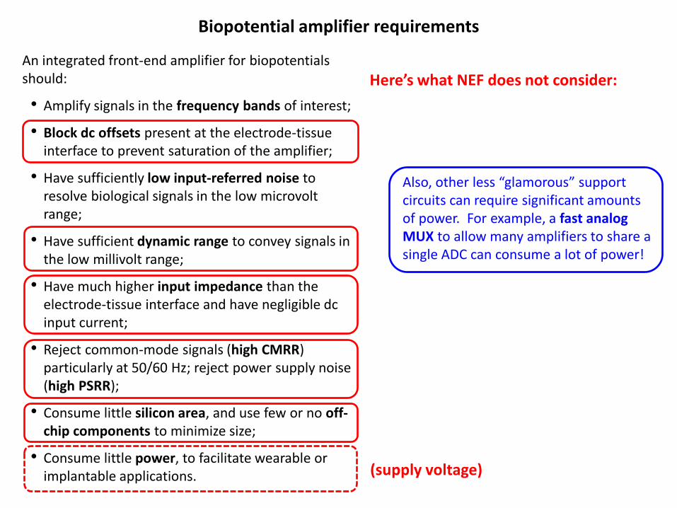
An integrated front-end amplifier for biopotentials should:
• Amplify signals in the frequency bands of interest;
• Block dc offsets present at the electrode-tissue interface to prevent saturation of the amplifier;
• Have sufficiently low input-referred noise to resolve biological signals in the low microvolt range;
• Have sufficient dynamic range to convey signals in the low millivolt range;
• Have much higher input impedance than the electrode-tissue interface and have negligible dc input current;
• Reject common-mode signals (high CMRR) particularly at 50/60 Hz; reject power supply noise (high PSRR);
• Consume little silicon area, and use few or no off-chip components to minimize size;
• Consume little power, to facilitate wearable or implantable applications.
Biopotential amplifier requirements
Here’s what NEF does not consider:
(supply voltage)
Also, other less “glamorous” support circuits can require significant amounts of power. For example, a fast analog MUX to allow many amplifiers to share a single ADC can consume a lot of power!

Outline
• Biopotential amplifier design
• Wireless cortical recording system (Utah Integrated Neural Interface)
• Electrophysiology recording lab on a chip (Intan Technologies RHD2000)
• Wireless telemetry: locust escape response
• Wireless telemetry: dragonfly in-flight prey capture

Power (~3 MHz coil; <30 mW) Configuration/control signals (~20 kbit/sec)
Data from 100 electrodes: RF (902-928 MHz ISM band, 345 kbit/sec)
Fully Wireless Neural Recording for Neuroprosthetic Applications
• Need to observe on the order of 100 neurons in motor and/or parietal cortex.
• Transcutaneous power and data transfer using inductive link and RF telemetry.
• Implant must operate below 30 mW to minimize tissue heating.
Utah electrode array
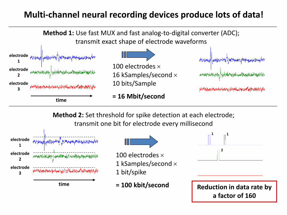
100 electrodes 16 kSamples/second 10 bits/Sample
= 16 Mbit/second
100 electrodes 1 kSamples/second 1 bit/spike
= 100 kbit/second
Multi-channel neural recording devices produce lots of data!
1 1
2
electrode 1
electrode 2
electrode 3
time
electrode 1
electrode 2
electrode 3
time Reduction in data rate by a factor of 160
Method 2: Set threshold for spike detection at each electrode; transmit one bit for electrode every millisecond
Method 1: Use fast MUX and fast analog-to-digital converter (ADC); transmit exact shape of electrode waveforms
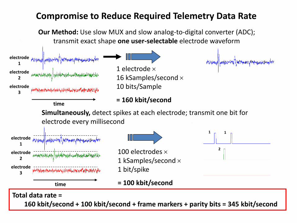
1 electrode 16 kSamples/second 10 bits/Sample
= 160 kbit/second
100 electrodes 1 kSamples/second 1 bit/spike
= 100 kbit/second
Compromise to Reduce Required Telemetry Data Rate
1 1
2
electrode 1
electrode 2
electrode 3
time
electrode 1
electrode 2
electrode 3
time
Simultaneously, detect spikes at each electrode; transmit one bit for electrode every millisecond
Our Method: Use slow MUX and slow analog-to-digital converter (ADC); transmit exact shape one user-selectable electrode waveform
Total data rate = 160 kbit/second + 100 kbit/second + frame markers + parity bits = 345 kbit/second

Benchtop Testing of Assembled Devices at University of Utah
Assembled device with reference wire
Power/command transmit coil (2.8 MHz)
Underside of coil is electrostatically shielded
(radial slits block eddy currents)
Teflon/glass spacer: 10 mm coil-to-coil distance
Telemetry received several cm away

Total power transmission distance: 21 mm Data telemetry (915 MHz) distance: 40 mm
In Vivo Testing of Fully Assembled Devices (Cat Somatosensory Cortex)
Electrode 0,1 Electrode 2,0
Electrode 0,1
Spike detection threshold set to -81 µV
Outline
• Biopotential amplifier design
• Wireless cortical recording system (Utah Integrated Neural Interface)
• Electrophysiology recording lab on a chip (Intan Technologies RHD2000)
• Wireless telemetry: locust escape response
• Wireless telemetry: dragonfly in-flight prey capture
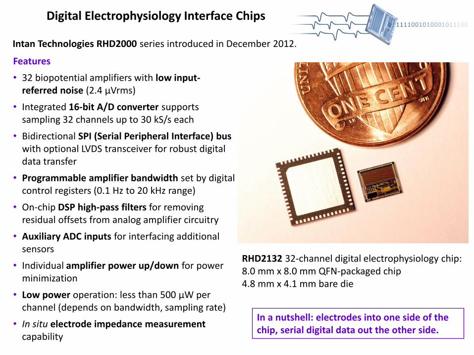
Digital Electrophysiology Interface Chips
Intan Technologies RHD2000 series introduced in December 2012.
RHD2132 32-channel digital electrophysiology chip: 8.0 mm x 8.0 mm QFN-packaged chip 4.8 mm x 4.1 mm bare die
Features
• 32 biopotential amplifiers with low input-referred noise (2.4 μVrms)
• Integrated 16-bit A/D converter supports sampling 32 channels up to 30 kS/s each
• Bidirectional SPI (Serial Peripheral Interface) bus with optional LVDS transceiver for robust digital data transfer
• Programmable amplifier bandwidth set by digital control registers (0.1 Hz to 20 kHz range)
• On-chip DSP high-pass filters for removing residual offsets from analog amplifier circuitry
• Auxiliary ADC inputs for interfacing additional sensors
• Individual amplifier power up/down for power minimization
• Low power operation: less than 500 μW per channel (depends on bandwidth, sampling rate)
• In situ electrode impedance measurement capability
In a nutshell: electrodes into one side of the chip, serial digital data out the other side.

RHD2132 Digital Electrophysiology Interface Chip – Simplified Diagram
Gain = 96 Gain = 2
Gain = 96 Gain = 2
Gain = 96 Gain = 2
Gain = 96 Gain = 2
in0
in1
in2
in31
ref_elec
analog
multiplexer
on chip
off chip
amplifier bandwidth
selection
auxin1
auxin2
auxin3
GND
VDD
channel
select
on-chip
RH1
on-chip
RH2
on-chip
RL
16-bit
ADC
½ VDD
temperature
sensor
16
6
MISO
MOSI
SCLK
CS
digital controller
with SPI interface
register
file misc. chip
configuration
bits
1.225V
voltage
reference
ADC_ref
auxout
control
Vref
10 nF
100 nF
Only two external capacitors required
Standard 4-wire SPI digital interface supports system modularity
Auxiliary analog inputs for external sensors (e.g., 3-axis accelerometer)
Auxiliary digital output (e.g. LED control)

RHD2000 Digital Electrophysiology Interface System
USB interface board supports up to 256 channels of recording at user-selectable sample rates between 1 kS/s and 30 kS/s.
USB 3.0 will support 2048+ channels.
Thin, flexible digital interface cables use LVDS (low-voltage differential signaling) to maintain high signal integrity over 10 meters using passive, daisy-chained cables.
Four SPI digital interface signals (LVDS); power

RHD2000 Digital Electrophysiology Interface System
USB interface board supports auxiliary general-purpose analog and digital I/O.
Selected amplifier channels can be routed to DACs for analog or audio output.
FPGA interface code and C++ API are 100% open source.

RHD2000 Digital Electrophysiology Interface System
Interface GUI software 100% open source, written in C++ with Qt libraries for Windows, Max, Linux compatibility.
signal frequency
sign
al a
mpl
itude
1 Hz 10 Hz 100 Hz 1 kHz 10 kHz
1 µV
10 µV
100 µV
1 mV
10 mV
neural
spikes
EMG
EMG (internal)
ECG
LFPs
EEG
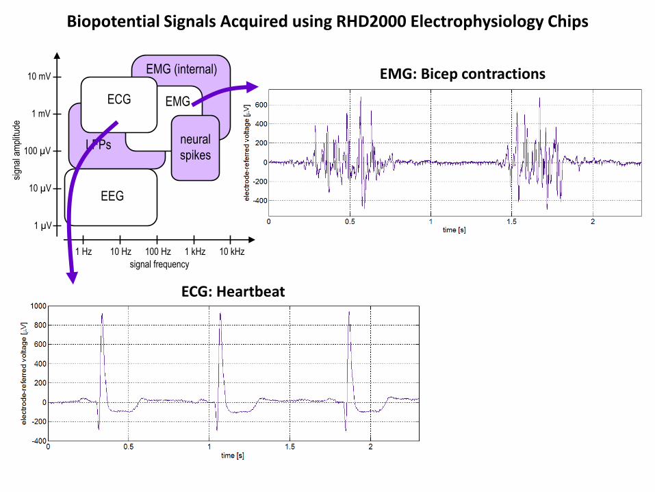
EMG: Bicep contractions
ECG: Heartbeat
Biopotential Signals Acquired using RHD2000 Electrophysiology Chips

Local field potentials (LFPs) and neural spikes from cortex of freely behaving mouse
signal frequency
sign
al a
mpl
itude
1 Hz 10 Hz 100 Hz 1 kHz 10 kHz
1 µV
10 µV
100 µV
1 mV
10 mV
neural
spikes
EMG
EMG (internal)
ECG
LFPs
EEG
Biopotential Signals Acquired using RHD2000 Electrophysiology Chips
(Data courtesy of Jakob Voigts at MIT, Brown University, and open-ephys.org)

Intan Technologies chips are currently used in more than 25 countries worldwide.
Outline
• Biopotential amplifier design
• Wireless cortical recording system (Utah Integrated Neural Interface)
• Electrophysiology recording lab on a chip (Intan Technologies RHD2000)
• Wireless telemetry: locust escape response
• Wireless telemetry: dragonfly in-flight prey capture

Hatsopoulos, Gabbiani, and Laurent, Science 270:1000, 1995
Locust cell response to looming target
Tools for Neuroscience: Wireless Telemetry from Walking/Jumping/Flying Insects
Certain neurons in insect brains respond selectively to looming visual stimuli.
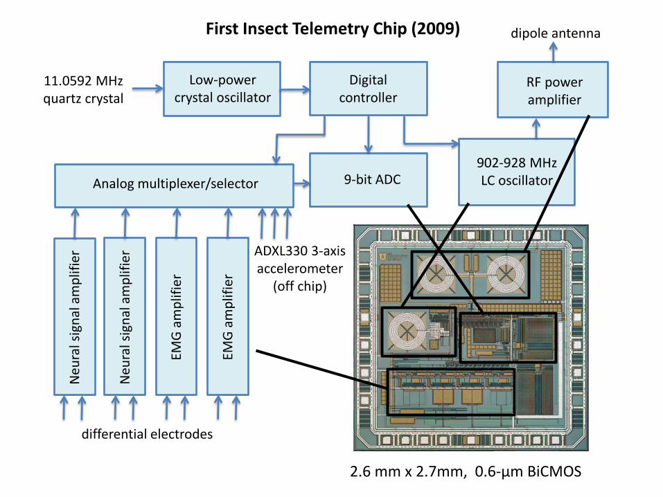
First Insect Telemetry Chip (2009)
902-928 MHz LC oscillator
RF power amplifier
dipole antenna
Digital controller
9-bit ADC Analog multiplexer/selector
Low-power crystal oscillator
11.0592 MHz quartz crystal
Neu
ral s
ign
al a
mp
lifie
r
Neu
ral s
ign
al a
mp
lifie
r
EMG
am
plif
ier
EMG
am
plif
ier
differential electrodes
ADXL330 3-axis accelerometer
(off chip)
2.6 mm x 2.7mm, 0.6-µm BiCMOS

Circuit board measures 13.0 mm x 9.5 mm.
Mass = 790 mg
(including batteries)
Supply current = 880 µA Battery life = 2 hours
Batteries
3-axis accelerometer quartz crystal
Utah telemetry chip
Complete Battery-Powered Wireless Telemetry Backpack
Telemetry Data (range >2 m)
• 2 neural channels (300 Hz – 5 kHz; 11.5 kSamples/s)
• 2 EMG channels (20 – 300 Hz; 1.9 kSamples/s)
• 3 acceleration channels (DC – 500 Hz; 1.9 kSamples/s)

Complete Battery-Powered Wireless Telemetry Backpack
Electrode wires are soldered onto PCB pads.
Receiver includes USB interface and realtime audio output.
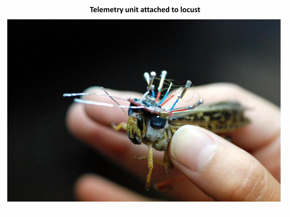
Telemetry unit attached to locust

Wireless Telemetry from Jumping Locust Audio = Neural Channel 1 (Right DCMD Neuron)
Courtesy Haleh Fotowat and Fabrizio Gabbiani, Baylor College of Medicine
R.R. Harrison, H. Fotowat, R. Chan, R.J. Kier, R. Olberg, A. Leonardo, and F. Gabbiani, “Wireless neural/EMG telemetry systems for small freely moving animals,” IEEE Transactions on Biomedical Circuits and Systems, vol. 5, pp. 103-111, April 2011.

Wireless Telemetry from Jumping Locust Audio = EMG Channel 2 (Leg Extensor Muscle)
Courtesy Haleh Fotowat and Fabrizio Gabbiani, Baylor College of Medicine
R.R. Harrison, H. Fotowat, R. Chan, R.J. Kier, R. Olberg, A. Leonardo, and F. Gabbiani, “Wireless neural/EMG telemetry systems for small freely moving animals,” IEEE Transactions on Biomedical Circuits and Systems, vol. 5, pp. 103-111, April 2011.

stimulus angular size
DCMD neuron
leg flexor EMG
leg extensor EMG
Z acceleration
take off
50°
200 μV
1 mV
2.5 mV
2 g
Wireless Telemetry from Jumping Locust
Data obtained wirelessly from a freely jumping locust, in response to an expanding visual stimulus (top trace). A neural signal from the DCMD neuron, plus two EMG signals were monitored (middle traces). Accelerometer data shows the jumping event (bottom trace).
H. Fotowat, R.R. Harrison, and F. Gabbiani, “Multiplexing of motor information in the discharge of a collision detecting neuron during escape behaviors,” Neuron 69: 147-158, January 13, 2011.

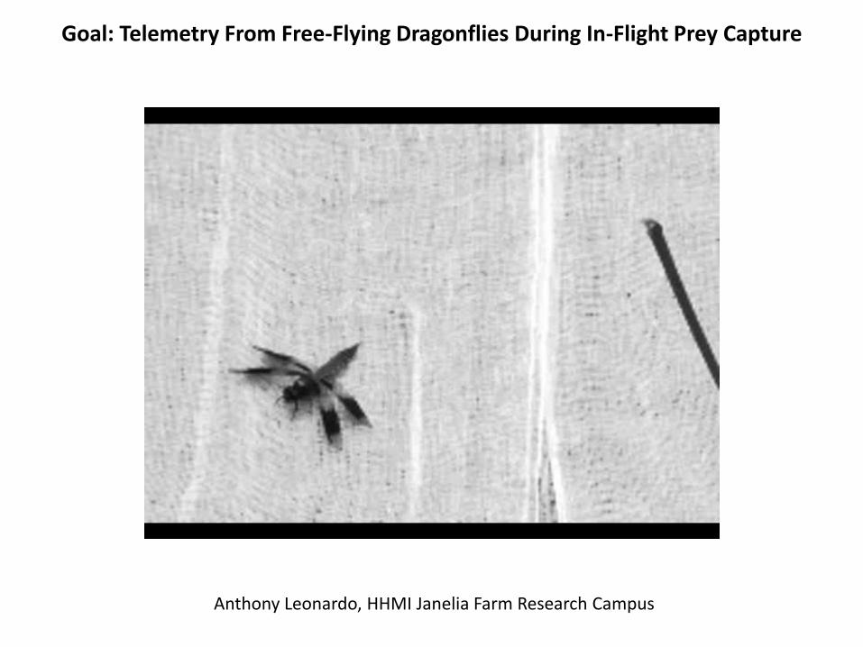
Goal: Telemetry From Free-Flying Dragonflies During In-Flight Prey Capture
Anthony Leonardo, HHMI Janelia Farm Research Campus
Goal: Telemetry From Free-Flying Dragonflies During In-Flight Prey Capture
Anthony Leonardo, HHMI Janelia Farm Research Campus
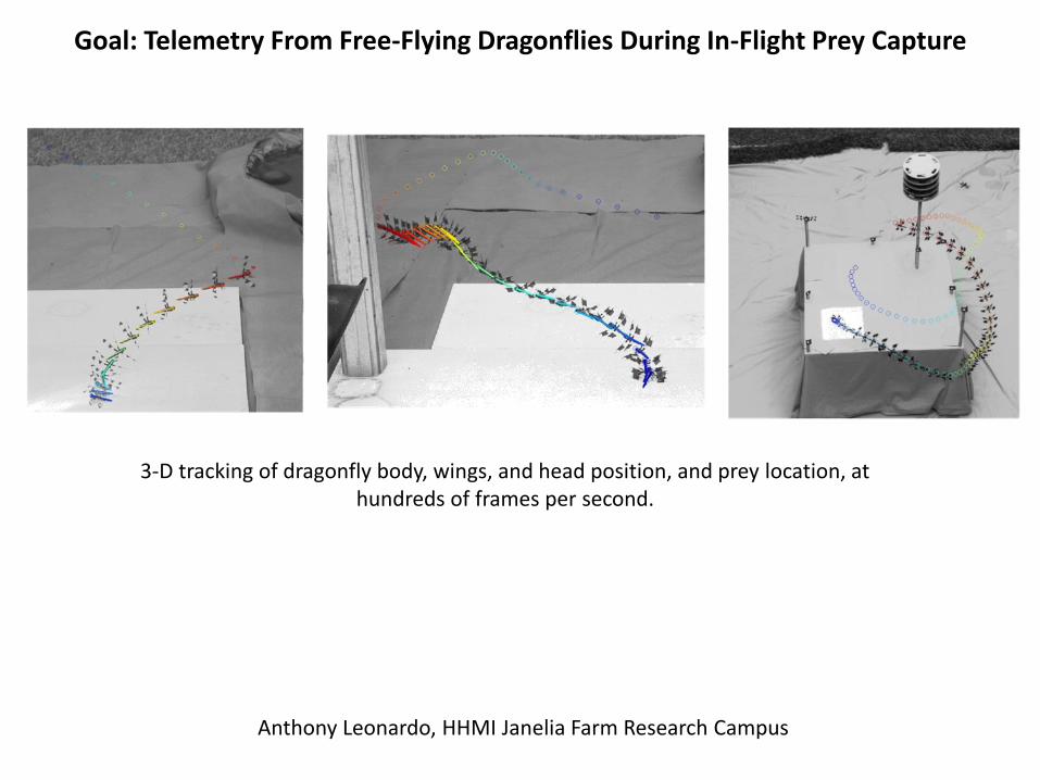
Goal: Telemetry From Free-Flying Dragonflies During In-Flight Prey Capture
Anthony Leonardo, HHMI Janelia Farm Research Campus
3-D tracking of dragonfly body, wings, and head position, and prey location, at hundreds of frames per second.

Next-Generation Insect Telemetry Unit
Mass = 790 mg 3.0V supply
Mass = 266 mg 1.5V supply
1.5V battery
chip
crystal

Further Size and Mass Reduction: Bare Die on Flex
Reduces mass by another 90 mg, to <180 mg with battery
Anthony Leonardo, HHMI Janelia Farm Research Campus

Spikes recorded wirelessly from target selective descending neuron (TSDN) on untethered, perched dragonfly
Wireless Data from Dragonfly Nerve Cord

Size comparison of Bug1, Bug2, and Bug2Flex
Bug1: 13 x 9 mm2, 790 mg
Bug2: 9 x 6 mm2, 280 mg
Bug2Flex: 6 x 5 mm2, 172 mg
(battery and antenna omitted in photo for clarity)

Far-field radiative power transfer (1/d2) at 915 MHz
– Higher power Tx longer range
– Unlike inductive coupling, longer range ≠ larger antenna!
Modulated backscatter return link
– 5 Mbps data rate, (11,16) Hamming encoding of each 11-bit ADC sample for
single bit error correction, double bit error detection (SECDED)
Forward Link : 915 MHz Power
Return Link: Modulated backscatter
5 Mbps
RF Tx/Rx
Baseband
PC
Base Station
Communication Channel
Telemetry IC
USB
RF Power + Data
Logic
Mux +
ADC
Neural Amps 1 - 10
EMG Amps 1 - 4
Elec
tro
des
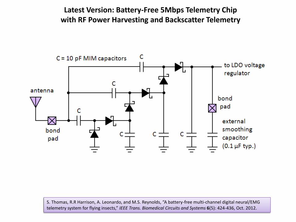
Latest Version: Battery-Free 5Mbps Telemetry Chip with RF Power Harvesting and Backscatter Telemetry
S. Thomas, R.R Harrison, A. Leonardo, and M.S. Reynolds, “A battery-free multi-channel digital neural/EMG telemetry system for flying insects,” IEEE Trans. Biomedical Circuits and Systems 6(5): 424-436, Oct. 2012.
with Matt Reynolds, Duke University
Latest Version: Battery-Free 5Mbps Telemetry Chip with RF Power Harvesting and Backscatter Telemetry
S. Thomas, R.R Harrison, A. Leonardo, and M.S. Reynolds, “A battery-free multi-channel digital neural/EMG telemetry system for flying insects,” IEEE Trans. Biomedical Circuits and Systems 6(5): 424-436, Oct. 2012.
10 neural amplifier channels sampled at 26.1 kS/s each • 250 Hz – 10 kHz bandwidth • ±2.4 mV range • 5.7 µV rms noise 4 EMG amplifier channels sampled at 1.63 kS/s each • 5 Hz – 700 Hz bandwidth • ±24 mV range • 43 µV rms noise
DC amplifier (gain < 1) monitors unregulated supply voltage

Latest Version: Battery-Free 5Mbps Telemetry Chip with RF Power Harvesting and Backscatter Telemetry
die photo (2.36 mm x 1.88 mm)
S. Thomas, R.R Harrison, A. Leonardo, and M.S. Reynolds, “A battery-free multi-channel digital neural/EMG telemetry system for flying insects,” IEEE Trans. Biomedical Circuits and Systems 6(5): 424-436, Oct. 2012.

Latest Version: Battery-Free 5Mbps Telemetry Chip with RF Power Harvesting and Backscatter Telemetry
Measured DC power consumption of 1.23mW
Amplifiers and ADC dominate: 1.0mW or 84%
Backscatter communication is only 19μW or 2%
Communication figure of merit is 4 pJ/bit
Eye diagram at 5 Mbps, 1 meter from receiver
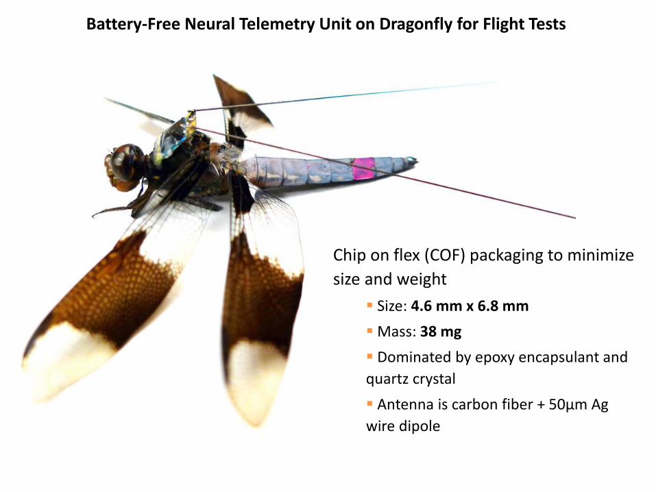
Battery-Free Neural Telemetry Unit on Dragonfly for Flight Tests
Chip on flex (COF) packaging to minimize
size and weight
Size: 4.6 mm x 6.8 mm
Mass: 38 mg
Dominated by epoxy encapsulant and
quartz crystal
Antenna is carbon fiber + 50μm Ag
wire dipole
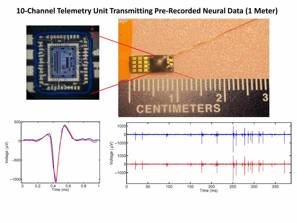
10-Channel Telemetry Unit Transmitting Pre-Recorded Neural Data (1 Meter)

Anthony Leonardo Haleh Fotowat Raymond Chan
Fabrizio Gabbiani Janelia Farm Research Campus
Howard Hughes Medical Institute Ashburn, Virginia, USA
Baylor College of Medicine Houston, Texas, USA
Matt Reynolds Stewart Thomas
Duke University Durham, North Carolina, USA
Acknowledgements – Insect Telemetry Projects