Wireless Structural Health Monitoring and the Civil ...memscon.com/content/content/files/05...
31
Anne Kiremidjian Professor Department of Civil and Environmental Engineering Stanford University Stanford, California MEMSCON October 7, 2010 Bucharest, Rumania
Transcript of Wireless Structural Health Monitoring and the Civil ...memscon.com/content/content/files/05...

Anne KiremidjianProfessor
Department of Civil and Environmental EngineeringStanford UniversityStanford, California
MEMSCONOctober 7, 2010
Bucharest, Rumania

ObjectivesPresent the current state of wireless structural health monitoringOutline challengesPresent future directions
2

OutlineMotivationWireless Monitoring System DesignExample applicationCurrent barriersConclusionFuture Directions
3

OutlineMotivationWireless Monitoring System DesignExample applicationCurrent barriers = future opportunitiesConclusion
4

Motivation ‐Why wireless? Advances in electronics –
sensors, wireless radios – range, bandwidth, reliability power harvesting to extend life
Low‐Cost solutionNo wiresNo installation of wiresCheaper sensorsSmall form factor
Flexible network architecture – reconfigurable systemFlexible computational platform – options for computing
Local – sensor level – embedded and updatableCentralized
5

OutlineMotivationWireless Monitoring System Design
Overall System DesignHardware FeaturesSoftware Features
Example applicationCurrent barriers = future opportunitiesConclusion
6
Wireless Structural System Components
Decision Support & Emergency Response
System
Data Analysis and Post-processing System
Synchronization
Structure -level analysis
Decision making
Signal Processing
Spectral Analysis
Feature Extraction & Damage Classification
Control CenterData
management and archiving
Data StorageManager on
site
Sensors & Network

8

Sensing Unit Design
Multiple sensors Acceleration –
Strong motion – 3DAmbient vibrations -3D
StrainTemperatureHumidity
ComputationalEngine
Data Acquisition and Management
Data Processing Through Embedded Algorithms
SensingSensingInterface
Vibrating wire Vibrating wire Strain SensorStrain SensorTemperatureTemperatureCorrosionCorrosion
AccelerometerAccelerometerWireless
CommunicationsNode ~ Mesh/HybridWireless Network
Low Power……
• Data stored on board on SD card• Multi-sensor data collection• Data converted into damage
assessments and alerts• Wireless transmission of processed
information • Low power – long-duration autonomous
operation• Small size and low cost
HumidityHumidity
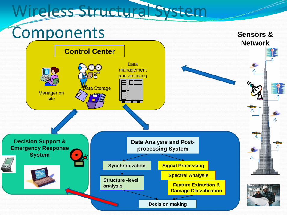
Sensing Unit Design ‐ ChronologyFive Generations of Sensing Unit Design
1996 – Straser, Kiremidjian and MengSingle 2D accelerometer, wireless modem, single supervisory microprocessorproof of concept with field test of 5 units
2000 – Lynch, Law and KiremidjianSingle 2D accelerometer, wireless modem, dual microprocessor, smaller form, lower power consumptionVerification with laboratory test followed by subsequent field tests
2002 – Mastroleon and Kiremidjian – multiple sensors2006 – Wang and Law – multiple sensors, increased wireless transmission range, data streaming with embedded compression algorithms2007 – current unit

Sensing Unit DesignFeatures of 5th Generation Design
Sensors Dual accelerometer – 24 bit A/D converter
3D strong motion – +2/10g, 200Hz sampling rate3D ambient vibration – 10‐4g, 200Hz sampling rate,
Strain gages with three resistancesTemperature sensorHumidity sensor
Dual microprocessorSupervisory Computational
802.15.4 radio module – Zig‐Bee compliant for wireless sensingLocal storage – mini SD card

Sensing unitsInternal view Mounted unit

Wireless Communications Network
Star, mesh and hybrid topologies for wireless communications networks
Fundamental Building blocks

Damage Detection AlgorithmsMain approach
Use statistical pattern classification and signal processing methods
Use single sensor pre‐ and post‐ damage measurements
Computationally efficient ‐ local micro‐processing
Independent of the sensor – can be used with acceleration, strain, etc.
Scalable with increased sensor density
Reduces amount of transmitted data – power saving
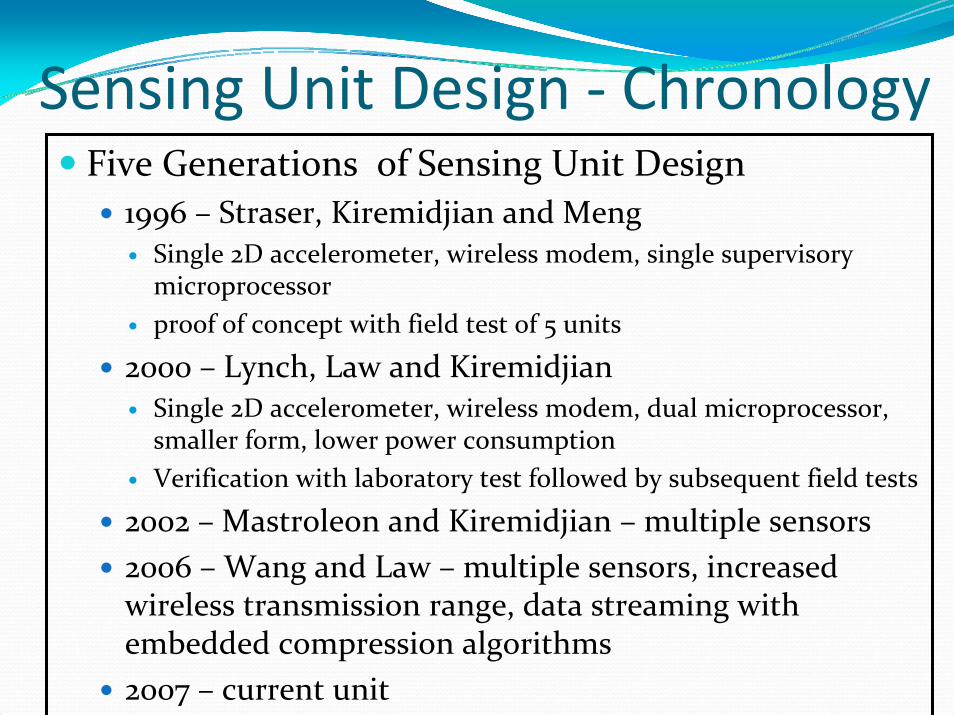
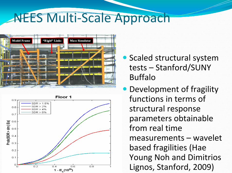
NEES Multi‐Scale Approach
Single column tests –UNR and UC‐BerkeleyDevelopment of rotation algorithm for wireless sensors (Allen Cheung, Stanford, 2008)Direct earthquake damage identification

Layout of Test Bridge and Instrumentation

Decision Support System‐MonitorinMode

Concrete spalling and exposure or rebar
Test Schedule – 4‐span Bridge Test at UNR
Baseline Signals
Major cracks at base of col. & spalling
Minor cracks at base of column
Rebar buckling/ breaking; concrete pouring out of core
Major cracks at base of col. & spalling

Final Test – White Noise
Test Damage MeasureReno - Setup Day DC1 and DC2 baselineMild Shaking Day 1, White Noise 21.05Mild Shaking Day 2, White Noise 21 36.79Mild Shaking Day 3, White Noise 41 56.97Final Test Day, White Noise Run 51 59.80

Column Device
Test Damage Measure
Reno - Setup Day DC1 and DC2
baseline
Mild Shaking Day 1, White Noise
21.05
Mild Shaking Day 2, White Noise 21
36.79
Mild Shaking Day 3, White Noise 41
56.97
Final Test Day, White Noise Run 51
59.80
NEES Multi‐Scale Approach
Scaled structural system tests – Stanford/SUNY BuffaloDevelopment of fragility functions in terms of structural response parameters obtainable from real time measurements – wavelet based fragilities (Hae Young Noh and Dimitrios Lignos, Stanford, 2009)

Decision Support SystemVisual representation of the structureVisual representation locations of the wireless systemInterface to wireless networkSystem command and control center Display results of monitoring analysesIssue alerts

Decision Support SystemProvide support for decision making for follow‐on actionsEnable web services for
wide distribution of alerts and other informationremote access by operators and other users.

OutlineMotivationWireless Monitoring System DesignExample applicationCurrent barriersConclusion
24

Current BarriersSensors for specific types of damage ‐ e.g.
CorrosionCrackDisplacement
Scalable and robust wireless network systemSignal lossCommunication barriersSensor durability and continued operation
Robust and reliable damage diagnosis and prognosis algorithmsReliability of long term power supply
25

Current Barriers (cont’d)Limited demonstrations
Laboratory Field ***
No standards or guidelines for development and manufacturing sensing units, sensor networks, etc.Existing legacy sensor companies unwilling to invest in new developmentsUnwillingness of profession to take the risk (or invest in proofs of concept)
26

OutlineMotivationWireless Monitoring System DesignExample applicationCurrent barriersConclusionFuture directions
27

ConclusionWireless monitoring systems – inevitable part of the futureSignificant applications throughout Asia, very limited elsewhereMust combine structural with other monitoring systems, e.g.
Building environmental/energy/lighting/security monitoringBridge, highway, tunnel, pipeline, transmission line, etc. management systems
Key to success is providing information and not just data
28

OutlineMotivationWireless Monitoring System DesignExample applicationCurrent barriersConclusionFuture directions
29

Future directionsInstrument key structures and demonstrate utility of such systemsHave a multi‐scale approach – provide different systems – one system does not fit all applications
Just an alarmComplete damage diagnosis and decision support for future actionsSystems that combine diagnosis, prognosis and repair actions
30

Future directionsDevelop the means for providing information to designers/builders at various stages of construction/use for future design purposesSystems should have different levels of interface sophistication
Technical user/decision makerManagement level decision maker with limited technical expertiseCommon citizen
31