WIRELESS SMART SECURITY SYSTEM (SSS) - POLITesi Smart... · E-mail: [email protected] ....
85
WIRELESS SMART SECURITY SYSTEM (SSS): An Application for Global Vehicle Monitoring BY Author: MD. FASIUL ALAM (ID: 767632) Supervisor: Professor Dr. Franco Zappa A THESIS SUBMITTED IN PARTIAL FULFILMENT OF THE REQUIREMENT FOR THE DEGREE OF MASTER OF SCIENCE IN ELECTRONIC SYSTEM ENGINEERING POLITECNICO DI MILANO, ITALY Academic Year: 2011-2012
Transcript of WIRELESS SMART SECURITY SYSTEM (SSS) - POLITesi Smart... · E-mail: [email protected] ....
WIRELESS SMART SECURITY SYSTEM (SSS):
An Application for Global Vehicle Monitoring
BY
Author: MD. FASIUL ALAM (ID: 767632)
Supervisor: Professor Dr. Franco Zappa
A THESIS SUBMITTED IN PARTIAL FULFILMENT
OF
THE REQUIREMENT FOR THE DEGREE OF
MASTER OF SCIENCE
IN
ELECTRONIC SYSTEM ENGINEERING
POLITECNICO DI MILANO, ITALY Academic Year: 2011-2012
Wireless Smart Security System (SSS): An Application for Global Vehicle Monitoring
Politecnico di Milano
Page ii
Declaration This is to certify that the Thesis/Project entitled “WIRELESS GLOBAL VEHICLE SMART SECURITY SYSTEM (SSS): An Application for Global Vehicle Monitoring” has been completed satisfactorily and no part of the work has been published elsewhere for the requirement or fulfillment of any degree. ………………............ Md. Fasiul Alam ID: 10335795, Matricola: 767632 M. Sc. In Electronic system engineering Politecnico di Milano. Milan, Italy. Email: [email protected] ………………............ Dr. Franco Zappa Professor, Department of Elettronica e Informazione Politecnico di Milano, Milan, Italy. E-mail: [email protected]
Wireless Smart Security System (SSS): An Application for Global Vehicle Monitoring
Politecnico di Milano
Page iii
To my parents
Wireless Smart Security System (SSS): An Application for Global Vehicle Monitoring
Politecnico di Milano
Page iv
Acknowledgements I would like to express my sincere thanks to my project supervisor, Dr. Franco Zappa, for his patience, guidance and advice throughout the year, which proved valuable for the success of this project. Thanks to Mr. Marco Pannulo, system engineer, my dearest Mr. Alessandro de Rossi, technical Manager, all Lab assistant of Cobra Automotive technologies, heartfelt thanks to all of them for their support and encouragement throughout the year. Special thanks to my friends and family members for their endless support and encouragements. Finally, thanks to all Politecnico di Milano’s members for giving me chance to study in this famous university as a scholarship awarded student.
Wireless Smart Security System (SSS): An Application for Global Vehicle Monitoring
Politecnico di Milano
Page v
Abstract Security and privacy are most concern matters with the advanced of technology. The importance of smart security for the vehicle/fleet is now an important issue in the global world. Everyday many of us lose their vehicle for the lack of modern security equipments. Though there are some security system are available in the market but wireless system are not so common to us. Therefore, a WIRELESS SMART SECURITY SYSTEM (SSS): an Application for Global Vehicle Monitoring has been developed to recover that limitation. It can be used for ensuring security for vehicle and fleet for a safe parking, driving, detecting unauthorized person and so on. The system detects the different situation and inform automatically to the desired destination without any human intervention. 2.4 GHz wireless based security system is an intelligent stand alone management system in the vehicle with proven performance and stability. The aim of an engineering design is to produce maximum output with minimum cost involved. According to that, the designed system involves low cost yet offers better performance in comparison to other security system available. Microcontroller is the heart of this security system which is interfaced with many sensors, wireless devices, GPS/GSM Module, alarm circuit, engine cranking and so on. Microcontroller tests different situation of the systems and gives output to the alarm circuit as well as send the command to the desired centre for stopping the unauthorized entrance to the vehicle. It can also easily find the location where the situation occurred. The results obtained stand as a proof of concept for the credibility of implementing wireless based Security System. Achieved result of the project is encouraging to me. Yet, the results still need further analysis and improvements to be made. Using advanced software’s and fast FPGA based devices can help in gathering more data and control further processes.
Wireless Smart Security System (SSS): An Application for Global Vehicle Monitoring
Politecnico di Milano
Page vi
Astratto (Abstract in Italian Language)
Sicurezza e privacy sono la maggior parte delle questioni riguardano con l'avanzata della tecnologia. L'importanza della sicurezza intelligente per il veicolo / flotta è ormai una questione importante nel mondo globale. Ogni giorno molti di noi perdono il loro veicolo per la mancanza di attrezzature di sicurezza moderne. Anche se ci sono alcuni sistemi di sicurezza sono disponibili sul mercato, ma il sistema wireless non sono così comuni a noi. Pertanto, un sistema di sicurezza wireless SMART (SSS): un'applicazione per il monitoraggio globale del veicolo è stato sviluppato per recuperare tale limitazione. Esso può essere utilizzato per garantire la sicurezza per veicoli e delle flotte per un parcheggio sicuro, di guida, rilevando persona non autorizzata e così via. Il sistema rileva la diversa situazione e informare automaticamente alla destinazione desiderata senza alcun intervento umano. Wireless a 2,4 GHz sistema di sicurezza è un sistema intelligente di gestione autonoma del veicolo dalle prestazioni comprovate e la stabilità. L'obiettivo di una progettazione ingegneristica è quello di produrre il massimo rendimento con minimo costo coinvolti. Secondo tale, il sistema progettato comporta bassi costi ma offre prestazioni migliori rispetto al sistema di sicurezza altro disponibile. Microcontrollore è il cuore di questo sistema di sicurezza, che si interfaccia con molti sensori, dispositivi wireless, GPS / GSM del modulo, circuito di allarme, l'avviamento del motore e così via. Microcontrollore verifica diversa situazione dei sistemi e dà uscita al circuito di allarme e inviare il comando al centro desiderato per fermare l'ingresso non autorizzato del veicolo. Si può anche facilmente trovare la posizione in cui la situazione si è verificato. I risultati ottenuti presentarsi come un proof of concept per la credibilità di attuare wireless sistema di sicurezza basato su. Risultato ottenuto del progetto è incoraggiante per me. Eppure, i risultati ancora bisogno di ulteriori analisi e miglioramenti da apportare. Utilizzando avanzati software e dispositivi basati su FPGA veloci possono aiutare a raccogliere più dati e controllare i processi di ulteriori.
Wireless Smart Security System (SSS): An Application for Global Vehicle Monitoring
Politecnico di Milano
Page vii
Contents DECLARATION ......................................................................................................................................... II
DEDICATION ............................................................................................................................................ III
ACKNOWLEDGEMENTS ........................................................................................................................ IV
ABSTRACT ................................................................................................................................................. V
ASTRATTO (ABSTRACT IN ITALIAN LANGUAGE) .......................................................................... VI
CONTENTS ................................................................................................................................................... VII LIST OF FIGURES ........................................................................................................................................... IX LIST OF TABLES .............................................................................................................................................. X
CHAPTER 1 ................................................................................................................................................. 1
1.1 INTRODUCTION......................................................................................................................................... 1 1.2 MOTIVATION FOR THESIS ......................................................................................................................... 2
CHAPTER 2 ................................................................................................................................................. 3
2.1 MAJOR BLOCK DIAGRAMS ....................................................................................................................... 3 2.2 WHY STA 2051 MICROPROCESSOR FOR SMART SECURITY SYSTEM (SSS)? ............................................ 4 2.3 MEMORY .................................................................................................................................................. 7 2.4 PORT 0 FEATURES ..................................................................................................................................... 7 2.5 PORT 1 FEATURES ..................................................................................................................................... 9 2.6 PORT 2 FEATURES ................................................................................................................................... 10 2.7 I/O EXPANDER ........................................................................................................................................ 12 2.8 SECONDARY MICROCONTROLLER .......................................................................................................... 13 2.9 PIN CONNECTION .................................................................................................................................... 14 2.10 EXTERNAL CONNECTION BLOCK DIAGRAM ......................................................................................... 17 2.11 GPS BLOCK .......................................................................................................................................... 17 2.12 TEMPERATURE SENSOR ........................................................................................................................ 19 2.13 CAN INTERFACE .................................................................................................................................. 20 2.14 GSM/GPRS BLOCK .............................................................................................................................. 21 2.15 I2C INTERFACE ..................................................................................................................................... 22 2.16 LED INDICATOR ................................................................................................................................... 22 2.17 INPUT/OUTPUT ..................................................................................................................................... 22 2.18 AUDIO INTERFACE ................................................................................................................................ 23 2.19 REMOTE KEY INTERFACE ..................................................................................................................... 23 2.20 DRIVERCARD ....................................................................................................................................... 23 2.21 POWER STAGE ...................................................................................................................................... 23
CHAPTER 3 ............................................................................................................................................... 26
3.1 SYSTEM ARCHITECTURE ........................................................................................................................ 26 3.2 SYSTEM INTERFACES.............................................................................................................................. 27 3.3 DEBUGGING AND PROGRAMMING .......................................................................................................... 27 3.4 SYSTEM INITIALIZATION SEQUENCE ...................................................................................................... 28 3.5 DRIVERS LIST ......................................................................................................................................... 29 3.6 SERIAL INTERFACE ................................................................................................................................. 30 3.7 EMBEDDED FLASH MEMORY INTERFACE ............................................................................................... 31 3.8 INPUT/OUTPUT INTERFACE .................................................................................................................... 32
CHAPTER 4 ............................................................................................................................................... 35
4.2 SHK - SHOCK DETECTION ALERT WITH SYSTEM SET (SHOCK DISSUASION SEQUENCE) ......................... 35 4.3 INT – INTRUSION ALERT WITH SYSTEM SET (THEFT SEQUENCE) ........................................................................... 35 4.4 MOT - VEHICLE MOTION ALERT WITH SYSTEM SET (THEFT SEQUENCE)................................................ 35 4.5 MOT - VEHICLE MOTION ALERT WITH SYSTEM UNSET (THEFT SEQUENCE) (TNO NORMATIVE) ........... 36
Wireless Smart Security System (SSS): An Application for Global Vehicle Monitoring
Politecnico di Milano
Page viii
4.6 MOT - AUTOZONE VEHICLE MOTION ALERT (THEFT SEQUENCE) ......................................................... 36 4.7 IGN - IGNITION KEY ON ALERT WITH SYSTEM SET (THEFT SEQUENCE) ................................................ 38 4.8 SAB – MAIN BATTERY TAMPER ALERT WITH SYSTEM SET (THEFT SEQUENCE) ..................................... 38 4.9 SAB – MAIN BATTERY TAMPER ALERT WITH SYSTEM UNSET ............................................................... 38 4.10 LNB - BUS TAMPER ALERT WITH SYSTEM SET (THEFT SEQUENCE) ...................................................... 39 4.11 LNB - BUS TAMPER ALERT WITH SYSTEM UNSET ................................................................................. 39 4.12 GPS - GPS ANTENNA SABOTAGE ALERT WITH SYSTEM SET OR UNSET ............................................... 39 4.13 GPO - GPS ANTENNA STATUS OK ALERT WITH SYSTEM SET OR UNSET ............................................. 39 4.14 ACC - BACKUP BATTERY LOW ALERT WITH SYSTEM SET/UNSET ......................................................... 39 4.15 BAT - MAIN BATTERY LOW ALERT WITH SYSTEM SET/UNSET ............................................................. 40 4.16 ENG - ENGINE ON/OFF ALERT WITH SYSTEM SET/UNSET .................................................................... 40 4.17 S1F & S1S - SENSOR 1 ANALOG INPUT ALERTS WITH SYSTEM SET/UNSET ........................................... 40 4.18 S2D & S2U - SENSOR 1 DIGITAL INPUT ALERTS (DOWN, UP) ................................................................. 40 4.19 SPD - HORIZONTAL SPEED ALERT ........................................................................................................ 40 4.20 ZONE IN/ZONE OUT ALERT (ZIN/ZOUT) ................................................................................................ 41 4.21 ALERT RK1 ÷ 4 USER ALERTS ............................................................................................................. 41 4.22 COD ALERT .......................................................................................................................................... 41 4.23 DCB ALERT .......................................................................................................................................... 41 4.24 RKB ALERT ........................................................................................................................................... 42
CHAPTER 5 ............................................................................................................................................... 43
Event Descriptions ............................................................................................................................. 43 5.1 INITIALIZATION EVENT .......................................................................................................................... 43 5.2 USER PROGRAMMING TRACKING EVENTS .............................................................................................. 43 5.3 THEFT TRACKING EVENTS ..................................................................................................................... 44 5.4 THEFT SEQUENCE MANAGEMENT .......................................................................................................... 45 5.5 SHOCK SENSOR MANAGEMENT .............................................................................................................. 45 5.6 PERIMETRIC SENSOR MANAGEMENT ...................................................................................................... 46 5.7 COMMANDS, ANSWERS, ACKNOWLEDGEMENTS, ERRORS ...................................................................... 47 5.8 SSS OPERATING MODES ........................................................................................................................ 48
First Installation Mode ....................................................................................................................... 48 Sleep Mode ........................................................................................................................................ 50 Normal Mode ..................................................................................................................................... 50
5.9 SSS ENGINE LOCKS AND PROTECTION LEVELS ...................................................................................... 51 User Engine Lock ................................................................................................................................ 51 Low Server Engine Lock (Secure Lock/Unlock) ................................................................................... 52 High Server Engine Lock (Theft Lock/Unlock) .................................................................................... 52
5.10 COMMANDS .......................................................................................................................................... 52 Enter Sleep Mode (Kill) ....................................................................................................................... 52 Car Lock / Unlock ............................................................................................................................... 52 Secure Lock/Unlock ............................................................................................................................ 53 Theft Lock/Unlock .............................................................................................................................. 53 Stop Theft Alert .................................................................................................................................. 53 Horn ................................................................................................................................................... 53 Car Finder / User Dissuasion Sequence .............................................................................................. 53 Radio Key or Driver Card Learning Mode On/Off ............................................................................... 53 Module Query Data ........................................................................................................................... 54 Module Query Forced Data ................................................................................................................ 54 Parameters Setup .............................................................................................................................. 54 Parameters Query and Parameters Answer ...................................................................................... 54 Configuration Setup ........................................................................................................................... 54 Configuration Query and Configuration Answer ............................................................................... 55 Sensors Setup ..................................................................................................................................... 55
5.11 SENSORS QUERY AND SENSORS ANSWER ............................................................................................ 55
Wireless Smart Security System (SSS): An Application for Global Vehicle Monitoring
Politecnico di Milano
Page ix
Zone Setup ......................................................................................................................................... 55 Zone Cancel ........................................................................................................................................ 55 Zone Query and Zone Answer ............................................................................................................ 55 User Profile Setup .............................................................................................................................. 55 User Profile Query and User Profile Answer ...................................................................................... 56
5.12 STAND-ALONE 5-BUTTONS RADIO KEY FUNCTIONALITIES .................................................................. 56 5.13 DRIVER CARD & RADIO-KEY MIXED MODE FUNCTIONALITIES........................................................... 56 5.14 OVERRIDE CODE .................................................................................................................................. 57 5.15 HI-JACK PUSH BUTTON ........................................................................................................................ 58 5.16 POWER MANAGEMENT ......................................................................................................................... 58 5.17 GSM MANAGEMENT ............................................................................................................................ 59 5.18 GPS MANAGEMENT ............................................................................................................................. 59 5.19 SMS FIFO ............................................................................................................................................. 60 5.20 TIME STAMPING ................................................................................................................................... 60 5.21 REMOTE LED ........................................................................................................................................ 60 5.22 BOOT LOADER ..................................................................................................................................... 61 5.23 GARAGE FUNCTION .............................................................................................................................. 61 5.24 TRANSPORT FUNCTION ........................................................................................................................ 61 5.25 PASSIVE ARMING/REARMING FUNCTION ............................................................................................. 61 5.26 FREE SIM CARD FUNCTION ................................................................................................................. 62 5.27 SMS PROTOCOL SECURITY .................................................................................................................. 62 5.28 THEFT TRACKING MASK ...................................................................................................................... 63 5.29 UPEA MODE ........................................................................................................................................ 63 5.30 IDENTIFICATION PROCEDURE 1 ............................................................................................................ 63 5.31 IDENTIFICATION PROCEDURE 2 ............................................................................................................ 65 5.32 BACKUP BATTERY MANAGEMENT ....................................................................................................... 65 5.33 FUNCTIONALITIES IMPROVEMENTS ...................................................................................................... 66 5.34 SUPPORT OF SIM CARD WITHOUT PIN CODE ENHANCED ....................................................................... 66 5.35 GIVE POSSIBILITY TO THE FITTER TO TEST THE PERIMETRY ................................................................. 66 5.36 ENABLE THE SHOCK ALERT AND THE SHOCK DISSUASION ALSO WHEN SYSTEM IS PASSIVE ARMED ... 66 5.37 BUS INTERFACE .................................................................................................................................... 67 5.38 CAN BUS FUNCTIONALITIES ................................................................................................................ 67 5.39 CAN BUS FUNCTIONALITIES WITH CLIENT/SERVER PROTOCOL .......................................................... 68 5.40 RADIO FREQUENCY 2.4 GHZ INTERFACE ............................................................................................. 69 5.41 RF 2.4 GHZ NETWORK PROTOCOL GENERAL CRITERIA ...................................................................... 70
CHAPTER 6 ............................................................................................................................................... 73
REFERENCES: .......................................................................................................................................... 74
List of Figures FIGURE 1: MAJOR BLOCK DIAGRAM OF THE SYSTEM ........................................................................... 3
FIGURE 2: MAJOR BLOCK DIAGRAM OF STA 2051 ............................................................................. 5
FIGURE 3: PINS CONNECTION DIAGRAM OF STA 2051 ....................................................................... 6
FIGURE 4: EXTERNAL CONNECTION OF THE SYSTEM ......................................................................... 17
FIGURE 5: BASIC SIGNAL PROCESSING ............................................................................................ 18
FIGURE 6: BASIC SIGNAL PROCESSING OF GPS MODULE ................................................................. 19
Wireless Smart Security System (SSS): An Application for Global Vehicle Monitoring
Politecnico di Milano
Page x
FIGURE 7: TYPICAL CONNECTION DIAGRAM ..................................................................................... 19
FIGURE 8: GSM ENGINE BLOCK DIAGRAM ........................................................................................ 21
FIGURE 9: POWER SUPPLY DIAGRAM .............................................................................................. 24
FIGURE 10: OVERALL SOFTWARE ARCHITECTURE ............................................................................ 26
FIGURE 11: BOOT ENABLES MODE FEATURE ACTIVATION .................................................................. 28
List of tables TABLE 1: SSS CDL OPEN/CLOSE TIMING ........................................................................................ 49
TABLE 2: DRIVER CARD & RADIO KEY MIXED MODE .......................................................................... 57
Wireless Smart Security System (SSS): An Application for Global Vehicle Monitoring
Politecnico di Milano
Page 1
Chapter 1 1.1 Introduction Wireless smart security system (SSS): an Application for Global Vehicle Monitoring is a new concept for the new generation device in a range of Remote Connection Devices targeted to Remote Vehicle Security and Control applications. A GSM (Global System for Mobile Communications) module, inside the system, allows the wireless communication between the mobile asset and the Server. A GPS (Global Positioning System) module, inside the system, allows the localization of the mobile asset. The key objective of the system is to have a very simple and powerful device which is easy to install and flexible enough to cover a large number of high-volume, Remote Vehicle Security and Control applications. The distinctive goal of the system is to implement a very effective and simple solution that is affordable and easy to deploy. The goal of the system is to guarantee a complete, Client-Server infrastructure that allows a global interconnection between mobile assets and fixed/mobile stations such as PCs-client, mobile phones, palm PC’s and so on. Server-side customized applications together with a secure and robust Communication Server, guarantee a secure access to the vehicle information. The Communication Server guarantees events handling, data management and data protection. The Application Server can be provided by any body. The wireless platform allows the user to communicate with the vehicle using a GSM network. Using a dedicated SMS protocol it is possible, via Server, to perform some actions on the vehicle and to receive information from the vehicle. The event (like intrusions, battery loss etc.) is just forwarded using automatic communication (e.g. sending automatically composed SMS messages) or it’s possible a voice interaction with the Vocal Application (using a personal mobile/fixed phone), for maximum user protection and comfort. In any case the localisation capability built in the system allows to associate the event information with a time and position stamping that greatly increases the effectiveness of the service. Microcontroller based device continue to rise more than ever before. Furthermore, with the increase of that devices application in recent year, the Microcontroller is the targeted at this new market. A Microcontroller is a chip, containing processor, memory and input/output function though in smaller capacity. It is a microprocessor emphasizing high integration, in contrast to a general purpose microprocessor. Microcontrollers are frequently used in automatically controlled products and devices such as automobile engine control system, remote controls, office machines, appliances, programmable interval timer, power tools and toys and analog to digital and digital to analog converter etc. By reducing the size, cost and power consumption compared to a design using a
Wireless Smart Security System (SSS): An Application for Global Vehicle Monitoring
Politecnico di Milano
Page 2
separate microprocessor, memory, input/ output device, microcontroller makes it economical to electronically control many more processes.
1.2 Motivation for thesis There are several objectives for this WIRELESS SMART SECURITY SYSTEM (SSS): an Application for Global Vehicle Monitoring project and thesis. The proposed system offers unparalleled confidence and security thanks to a unique dual-network system that continually monitors vehicle. Every vehicle protected by smart monitoring is constantly monitored in real time from central monitoring station. If an alert is triggered by the system, they'll know about it instantly. The system checks itself continuously to ensure that it's working properly, and that the network connection is functioning properly. That means user can relax, knowing their vehicle is always connected, protected and safe. There is disclosed a motor vehicle control system having a vehicle control unit located in the vehicle and a hand held portable control unit, which are in two-way communication. The vehicle control unit which is located in the motor vehicle includes a receiving antenna, a receiver, a decoder and a plurality of functional control circuits, with each control circuit for a respective functional operation of the vehicle such as ignition, starter activation, door locks, etc. The control unit in the motor vehicle also includes a transmitter and a scanner unit which has a like plurality of sensors for sensing the condition of the various functional operations such as the ignition, engine operation. The control unit transmits a radio frequency signal to the remote control unit, which indicates the condition of the sensed operations. The remote control unit has an antenna and receiver with an audio amplifier and speaker. The remote unit has a standard key pad in circuit to an encoder to produce a signal that is applied to the transmitter for transmission to the vehicle control unit. The main objectives are: 1. To launch a smart security system. 2. To save our valuable asset by this system 3. To know how to interface a Microcontroller with different electronic devices such as:
wireless card, driver card, engine cranking system, alarm circuit, sensors etc. 4. To implement the idea with low infrastructure porting to more standard and power-full OS
like portable SW architecture 5. To establish the concept of a security system that can increase our confidence level. 6. To get area’s information automatically without any human intervention. 7. To establish GSM/GPRS Capability
Wireless Smart Security System (SSS): An Application for Global Vehicle Monitoring
Politecnico di Milano
Page 3
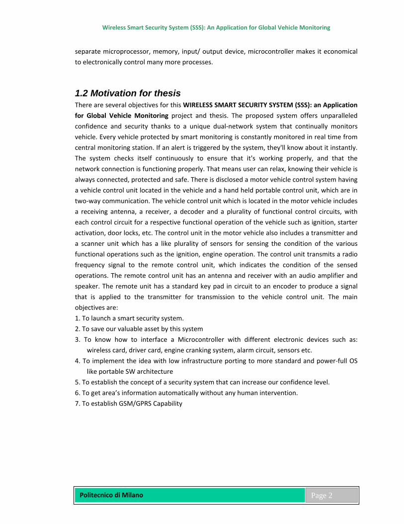
Chapter 2 Design and Implementation In order to fulfill the aim of the thesis, it is necessary to drive the hardware architecture design based on the understanding of the Microcontroller technology. The overall design of the project is shown in the following block diagram
2.1 Major Block Diagrams
Figure 1: Major Block Diagram of the system
Wireless Smart Security System (SSS): An Application for Global Vehicle Monitoring
Politecnico di Milano
Page 4
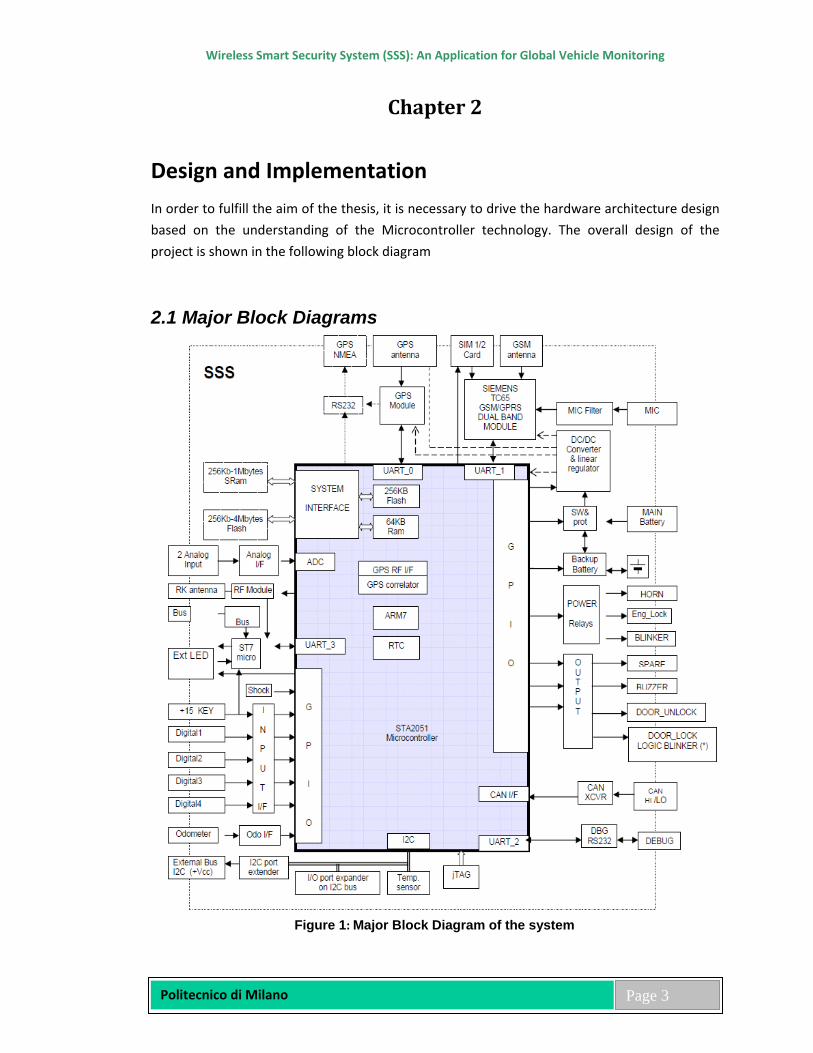
2.2 Why STA 2051 Microprocessor for Smart Security System (SSS)? The main microcontroller used in the system is an ST Microelectronics STA2051, 32-Bit single chip Baseband Controller for GPS and Telematic Applications. The question may arise why I chose this processor for Smart Security System (SSS). The reasons are STMicroelectronics’ STA2051 is a System-on-Chip implementing a complete GPS baseband including an ARM7TDMI 32-bit microcontroller, a 12-channel correlator and a 2-Mbit on-board Flash memory. Only one IC is required to complete the GPS chipset functionality – a single-chip radio front-end such as the STB5610. Thanks to its extra CPU computing power and a wide range of hosted peripherals – CAN, SPI, UART, I2C, USB and others, the STA2051 and its package option, STA2051E – with external memory interface – can also be used as a telematic platform allowing glueless connection to external devices including a GSM/GPRS module, smartcard and DSP for audio functions such as voice recognition and text-to-speech. The STA2051 can also address other automotive applications such as DSRC – data short range communication, car-radio controller and mobile computing platforms – PDA and smartphone. Here are the main features of STA2051: - ARM7TDMI 16/32 bit RISC CPU based host microcontroller - Complete Embedded Memory System: FLASH 256K bytes (100K erasing/programming
cycles) RAM 64K bytes. - External memory interface provides glue less support for up to four banks of external
SRAM, FLASH, ROM. - 12 channel GPS correlation DSP: no TCXO required, RTCA-SC159 / WAAS / EGNOS support - CMOS M8T (0.18 um) technology. - -40°C to 85°C operating temperature range - 144-pin TQFP144 package - 2.7V to 3.6V operating supply range for Input/Output periphery and A/D Converter
reference - 1.8V operating supply range for core supply provided either by internal Voltage Regulator
with external stabilization capacitor, or by external supply for higher power efficiency. - 0 - 66 MHz internal clock frequency managed by a Reset and Clock Control Unit; the unit is
able to provide low power modes (WAIT, SLOW, STOP, STANDBY) and to generate the internal clock from the external 16 MHz through integrated PLL
- 48 programmable General Purpose I/O, each pin programmable independently as digital input or digital output. 40 are multiplexed with peripheral functions; 16 can generate an interrupt on input level/transition
- Real time clock module with external 32 KHz low power clock and separate power supply to continue running during stand-by mode.
- 16-bit Watchdog Timer with 8 bits prescaler for system reliability and integrity.
Wireless Smart Security System (SSS): An Application for Global Vehicle Monitoring
Politecnico di Milano
Page 5
- CAN module compliant with the CAN specification V2.0 part B (active). The bit rate can be programmed up to 1 MBaud.
- Four16-bit programmable Timers with 7 bit prescaler, up to two input capture/output compare, one pulse counter function, one PWM channel with selectable frequency each.
- 4 channels 12-bit sigma-delta Analog to Digital Converter, single channel or multi channel conversion modes, single-shot or continuous conversion modes, sample rate 1 KHz (4 KHz when single channel), conversion range 0-2.5V
- Three Serial Communication Interfaces (UART) allow full duplex, asynchronous, communications with external devices, independently programmable TX and RX baud rates up to 250K baud.
- One UART adapted to suit Smart Card interface needs, for asynchronous SC as defined by ISO 7816-3; it includes SC clock generation.
Figure 2: Major Block Diagram of STA 2051
Wireless Smart Security System (SSS): An Application for Global Vehicle Monitoring
Politecnico di Milano
Page 6
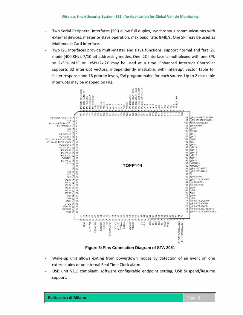
- Two Serial Peripheral Interfaces (SPI) allow full duplex, synchronous communications with external devices, master or slave operation, max baud rate: 8Mb/s. One SPI may be used as Multimedia Card interface.
- Two I2C Interfaces provide multi-master and slave functions, support normal and fast I2C mode (400 KHz), 7/10 bit addressing modes. One I2C Interface is multiplexed with one SPI, so 2xSPI+1xI2C or 1xSPI+2xI2C may be used at a time. Enhanced Interrupt Controller supports 32 interrupt vectors, independently maskable, with interrupt vector table for faster response and 16 priority levels, SW programmable for each source. Up to 2 maskable interrupts may be mapped on FIQ.
Figure 3: Pins Connection Diagram of STA 2051
- Wake-up unit allows exiting from powerdown modes by detection of an event on one
external pins or on internal Real Time Clock alarm - USB unit V1.1 compliant, software configurable endpoint setting, USB Suspend/Resume
support.
Wireless Smart Security System (SSS): An Application for Global Vehicle Monitoring
Politecnico di Milano
Page 7
- High Level Data Link Controller (HDLC) unit support full duplex operating mode, NRZ, NRZI, FM0 and MANCHESTER modes, internal 8bit Baud Rate Generator.
2.3 Memory The STA2051 microcontroller features 256 Kb internal Flash memories and 64Kb internal RAM. These external memory banks can be addressed by the main microcontroller using dedicated pin. Pins D00 to D15 (signals DATA00 to DATA15) are the external data bus, 16bit wide. Pins A01 to A19 (signals ADDR00 to ADDR18) is to external address bus. Pins A20 to A22 (signals ADDR19 to ADDR21) are pins configured for external memory access Pin A0 (signals ADDR-NC) is not used in a 16 bit memory access. Read/Write Control pins are WEN0, WEN1 and RDN (signal MEM-WRITE0, MEM-WRITE1, MEM-READ). Enable pin are CSN0 (signal FLASH-EN) for Flash Bank memory and CSN1 (signal RAM-EN) for SRAM bank memory. External Flash size is from 2Mbit (256Kb) to 32Mbit (4Mb). The board can optionally address 64Mbit (8Mb) of external Flash by using A22 pin. External SRAM size is from 2Mbit (256Kb) to 8Mbit (1Mb).
2.4 Port 0 features Pin number (port.pin)
Pin description (datasheet)
Function Selected
Signal name (schematic)
Connector signal (referred to)
P0.0 P0.0/S0.MISO/U3.TX Uart3 TX (OUT Push-Pull)
COM-TXD_CLX -
P0.1 P0.1/S0.MOSI/U3.RX Uart3 RX COM-RXD_CLX - These pins are used for a full-duplex asynchronous communication port UART3. This feature is used to communicate with a ST7 secondary microcontroller. P0.2 P0.2/S0.SCLK/I1.SCL I2C port1 SCL I2C-SCK_BL1 I2C-SCK_BL0 P0.3 P0.3/S0.SSN/I1.SDA I2C port1 SDA I2C-SDA_BL1 I2C-SDA_BL0 These pins are used for a serial I2C interface (multipoint). This feature is used for control a temperature sensor and dual remote I/O expander. In the SSS are present an I2C extender function to remotes the I2C internal bus on the Main connector, for external application. P0.4 P0.4/S1.MISO OUT Push-Pull GSM-DTR_OL1 Jtag internal
connector This pin has two function (depends on the FW running status): BOOT MODE: This pin is used as output serial data in ST7 FLASH programming. NORMAL MODE: This pin is used (with GSM-TX, GSM-RX, GSM-RTS, GSM-CTS and GSM-DCD) for control/communication GSM/GPRS module Siemens TC65.
Wireless Smart Security System (SSS): An Application for Global Vehicle Monitoring
Politecnico di Milano
Page 8
P0.5 P0.5/S1.MOSI OUT Push-Pull GSM-SEL_OX0 - This pin can be used for select which UART port on a GSM TC65 P0.6 P0.6/S1.SCLK Interrupt Input TTL DIGITAL4_IL1 Jtag internal
connector This pin has two function (depends on the FW running status): BOOT MODE: This pin is used as input serial clock in ST7 FLASH programming. NORMAL MODE: This interrupt pin is used to sensing a generic input connected directly to main connector pin, for example a crash sensor. Input has a voltage protection and pull-up resistor. P0.7 P0.7/S1.SSN OUT Push-pull ISP-RST_IL1 Jtag internal
connector This pin is used to reset ST7 secondary processor. This pin not has pull-up/down. Normal state of this pin after reset must be “1”. NOTE: GSM-DTR, DIGITAL4, ISP-RST and ISP-SEL pins are used for ST7 programming interface P0.8 P0.8/U0.RX/U0.TX Uart0 RX GPS-RXD1_CLX - P0.9 P0.9/U0.TX/BOOT.0 Uart0 TX
(OUT Open Drain) GPS-TXD1_CLX -
These pins are used for a full-duplex asynchronous communication port UART0. These pins are used to communicate with a GPS module U-Blox (TIM-LC / 4A modules). The TX pin is used at power-up as alternative function BOOT.0 only if the BOOT-EN function is active. Normal state of this pin after reset is “0” same of BOOT-EN pin, to which it is connected via a diode. If a BOOT-EN function is activated, this pin after reset is “1”. P0.10 P0.10/U1.RX/U1.TX Uart1 RX GSM-RXD_IL0 - P0.11 P0.11/U1.TX/BOOT.1 Uart1 TX
(OUT Open Drain) GSM-TXD_OL1 -
These pins are used for a full-duplex asynchronous communication port UART1. These pins (with control signals GSM-RTS, GSM-CTS, GSM-DTR and GSM-DCD) are used to control/communicate with a Siemens TC65 dual band GSM/GPRS module. At power-up the TX pin is used as alternative function BOOT.1 only if BOOT_EN function is active. Normal state of this pin after reset is always “0”, forced via a pull-down resistor. P0.12 P0.12/SCCLK OUT Open Drain LED_OL1 LED_OH0 This pin is used for control the diagnostic led, in according with the ST7 secondary microcontroller. Normally LED is under priority control of ST7. Normal state is high impedance (level “1” open drain). State "0" means status LED is ON. NOTE: If push-pull output type selected, state “0” or “1” can override the status LED.
Wireless Smart Security System (SSS): An Application for Global Vehicle Monitoring
Politecnico di Milano
Page 9
P0.13 P0.13/U2.RX/T2.OCMPA Uart2 RX PRGM-RXD_IL1 RS232-RXD_IH0 P0.14 P0.14/U2.TX/T2.ICAPA Uart2 TX PRGM-TXD_OL1 RS232-
TXD_OH0 These pins are used for a full-duplex asynchronous communication port UART2. This feature is used to communicate with transceiver for external debug port OR with a transceiver for a LIN physical interface (or optional Kline). Use of this interface is controlled by RS232-EN and LIN-NSLP control pin. P0.15 P0.15/WAKEUP Reserved - - This pin is fixed pulled-down.
2.5 Port 1 features Pin number (port:pin)
Pin description (datasheet)
Function Selected
Signal name (schematic)
Connector signal (referred
to) P1.0 P1.0/T3.OCMPA/AIN.0 Analog input ANALOG1_IA1 ANALOG1_IA0 P1.1 P1.1/T3.ICAPA/AIN.1 Analog input ANALOG2_IA1 ANALOG2_IA0 P1.2 P1.2/T3.OCMPB/AIN.2 Analog input +30-MON_IA1 +30 P1.3 P1.3/T3.ICAPB/AIN.3 Analog input +VBATT-MON_IA1 +VBATT These four pins are used with an internal 12 bit A/D converter to measure slowly-changing signals. These pins are connected to input pin through a passive attenuation/protection network. Measured signals are: two external voltage from the main connector, main battery voltage and backup-battery voltage. P1.4 P1.4/T1.ICAPA Input Capt. CMOS ODOMETER_IL1 ODOMETER_IH
0 This pin is used for odometer pulse counter. P1.5 P1.5/T1.ICAPB OUT Push-Pull HORN_OH1 HORN-NO_BX0 This output controls the HORN relay output. Normal state is “0” (contact OPEN=Horn off). Output is active (contact CLOSE=Horn on) when pin is “1”. Output has an external pull-down resistor. P1.6 P1.6/T1.OCMPA OUT Push-Pull RK-EN_CL1 - This pin, when connected, is used to enable/disable the Radio receiver power supply (for Radio key and Driver Card recognition). Normal state is “0” (radio receiver ON). State “1” means power supply is disabled. P1.7 P1.7/T1.OCMPB OUT Push-Pull ISP-SEL_OH1 -
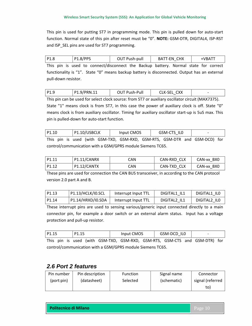
Wireless Smart Security System (SSS): An Application for Global Vehicle Monitoring
Politecnico di Milano
Page 10
This pin is used for putting ST7 in programming mode. This pin is pulled down for auto-start function. Normal state of this pin after reset must be “0”. NOTE: GSM-DTR, DIGITAL4, ISP-RST and ISP_SEL pins are used for ST7 programming. P1.8 P1.8/PPS OUT Push-pull BATT-EN_CHX +VBATT This pin is used to connect/disconnect the Backup battery. Normal state for correct functionality is “1”. State “0” means backup battery is disconnected. Output has an external pull-down resistor. P1.9 P1.9/PRN.11 OUT Push-Pull CLK-SEL_CXX - This pin can be used for select clock source: from ST7 or auxiliary oscillator circuit (MAX7375). State "1" means clock is from ST7, in this case the power of auxiliary clock is off. State "0" means clock is from auxiliary oscillator. Timing for auxiliary oscillator start-up is 5uS max. This pin is pulled-down for auto-start function. P1.10 P1.10/USBCLK Input CMOS GSM-CTS_IL0 - This pin is used (with GSM-TXD, GSM-RXD, GSM-RTS, GSM-DTR and GSM-DCD) for control/communication with a GSM/GPRS module Siemens TC65. P1.11 P1.11/CANRX CAN CAN-RXD_CLX CAN-xx_BX0 P1.12 P1.12/CANTX CAN CAN-TXD_CLX CAN-xx_BX0 These pins are used for connection the CAN BUS transceiver, in according to the CAN protocol version 2.0 part A and B. P1.13 P1.13/HCLK/I0.SCL Interrupt Input TTL DIGITAL1_IL1 DIGITAL1_IL0 P1.14 P1.14/HRXD/I0.SDA Interrupt Input TTL DIGITAL2_IL1 DIGITAL2_IL0 These interrupt pins are used to sensing various/generic input connected directly to a main connector pin, for example a door switch or an external alarm status. Input has a voltage protection and pull-up resistor. P1.15 P1.15 Input CMOS GSM-DCD_IL0 - This pin is used (with GSM-TXD, GSM-RXD, GSM-RTS, GSM-CTS and GSM-DTR) for control/communication with a GSM/GPRS module Siemens TC65.
2.6 Port 2 features Pin number (port:pin)
Pin description (datasheet)
Function Selected
Signal name (schematic)
Connector signal (referred
to)
Wireless Smart Security System (SSS): An Application for Global Vehicle Monitoring
Politecnico di Milano
Page 11
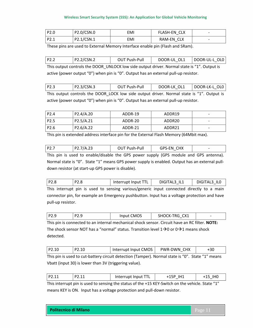
P2.0 P2.0/CSN.0 EMI FLASH-EN_CLX - P2.1 P2.1/CSN.1 EMI RAM-EN_CLX - These pins are used to External Memory Interface enable pin (Flash and SRam). P2.2 P2.2/CSN.2 OUT Push-Pull DOOR-UL_OL1 DOOR-UL-L_OL0 This output controls the DOOR_UNLOCK low side output driver. Normal state is “1”. Output is active (power output “0”) when pin is “0”. Output has an external pull-up resistor. P2.3 P2.3/CSN.3 OUT Push-Pull DOOR-LK_OL1 DOOR-LK-L_OL0 This output controls the DOOR_LOCK low side output driver. Normal state is “1”. Output is active (power output “0”) when pin is “0”. Output has an external pull-up resistor. P2.4 P2.4/A.20 ADDR-19 ADDR19 - P2.5 P2.5/A.21 ADDR-20 ADDR20 - P2.6 P2.6/A.22 ADDR-21 ADDR21 - This pin is extended address interface pin for the External Flash Memory (64Mbit max). P2.7 P2.7/A.23 OUT Push-Pull GPS-EN_CHX - This pin is used to enable/disable the GPS power supply (GPS module and GPS antenna). Normal state is “0”. State “1” means GPS power supply is enabled. Output has an external pull-down resistor (at start-up GPS power is disable). P2.8 P2.8 Interrupt Input TTL DIGITAL3_IL1 DIGITAL3_IL0
This interrupt pin is used to sensing various/generic input connected directly to a main connector pin, for example an Emergency pushbutton. Input has a voltage protection and have pull-up resistor. P2.9 P2.9 Input CMOS SHOCK-TRG_CX1 -
This pin is connected to an internal mechanical shock sensor. Circuit have an RC filter. NOTE: The shock sensor NOT has a “normal” status. Transition level 10 or 01 means shock detected. P2.10 P2.10 Interrupt Input CMOS PWR-DWN_CHX +30
This pin is used to cut-battery circuit detection (Tamper). Normal state is “0”. State “1” means Vbatt (input 30) is lower than 3V (triggering value). P2.11 P2.11 Interrupt Input TTL +15P_IH1 +15_IH0
This interrupt pin is used to sensing the status of the +15 KEY-Switch on the vehicle. State “1” means KEY is ON. Input has a voltage protection and pull-down resistor.

Wireless Smart Security System (SSS): An Application for Global Vehicle Monitoring
Politecnico di Milano
Page 12
P2.12 P2.12 OUT Push-Pull BLK_OH1 BLKx_OH0
This output control the BLINKER relay and Blinker low side output driver. Normal state is “0”. State "1" means Output is active (relay contact CLOSE=BLINKER ON). Output has an external pull-down resistor. P2.13 P2.13 OUT Push-Pull ENG_OH1 ENG-CUT_BX0 This output controls the ENGINE lock relay. Normal state is “0” (contact OPEN=Motor LOCK). State "1" means Output is active (relay contact CLOSE=Motor UNLock). Output has an external pull-down resistor. P2.14 P2.14 OUT Push-Pull GSM-RTS_OL1 - This pin is used (with GSM_TX, GSM_RX, CTS, DTR and DCD) for control/communication with a GSM/GPRS module Siemens TC65. P2.15 P2.15 OUT Push-pull I2C-EN_CHX - This pin is used to enable/disable the I2C external bus (with level translator and protection). Normal state is “0” (disabled). State “1” means external I2C bus is enabled. I2C switch have an internal pull-up resistor (at start-up I2C external BUS is enabled).
2.7 I/O expander As output pins of the microcontroller are not sufficient for handling all the SSS functions, an I/O expansion is required. For this purpose two Remote 8-bit I/O expander are provided, connected on the SSS internal I2C-bus, controlled by the controller via an internal I2C bus. Expander 1 is mapped on I2C bus with an address 40h for write and 41h for read operation (addr=000). Expander 2 is mapped on I2C bus with an address 42h for write and 43h for read operation (addr=001). NOTE: After reset the normal state of all expander output is “1”. This port must be correctly initialised! Expander 1 is used for the following external output control: Output (port:pin)
Signal name (schematic)
Function or action implemented
EXP1.0 Spare Out 2
Alternative function: Enable (0) or disable (1) the CANL-LS low side output driver
EXP1.1 Spare Out 3
Alternative function: Enable (0) or disable (1) the CANH-LS low side output driver
EXP1.2 CAN-SEL_CXX
This pin select High speed (0) or Low speed (1) transceiver input connection to Can controller.
EXP1.3 CAN-STB-HS_CHX
This pin enables (0) or disable (1) CAN High speed physical transceiver.
Wireless Smart Security System (SSS): An Application for Global Vehicle Monitoring
Politecnico di Milano
Page 13
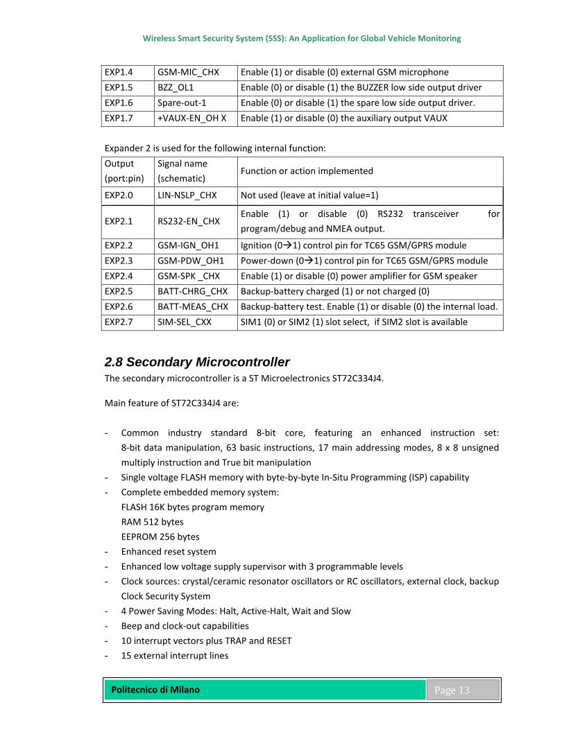
EXP1.4 GSM-MIC_CHX Enable (1) or disable (0) external GSM microphone EXP1.5 BZZ_OL1 Enable (0) or disable (1) the BUZZER low side output driver EXP1.6 Spare-out-1 Enable (0) or disable (1) the spare low side output driver. EXP1.7 +VAUX-EN_OH X Enable (1) or disable (0) the auxiliary output VAUX Expander 2 is used for the following internal function: Output (port:pin)
Signal name (schematic)
Function or action implemented
EXP2.0 LIN-NSLP_CHX Not used (leave at initial value=1)
EXP2.1 RS232-EN_CHX Enable (1) or disable (0) RS232 transceiver for program/debug and NMEA output.
EXP2.2 GSM-IGN_OH1 Ignition (01) control pin for TC65 GSM/GPRS module EXP2.3 GSM-PDW_OH1 Power-down (01) control pin for TC65 GSM/GPRS module EXP2.4 GSM-SPK _CHX Enable (1) or disable (0) power amplifier for GSM speaker EXP2.5 BATT-CHRG_CHX Backup-battery charged (1) or not charged (0) EXP2.6 BATT-MEAS_CHX Backup-battery test. Enable (1) or disable (0) the internal load. EXP2.7 SIM-SEL_CXX SIM1 (0) or SIM2 (1) slot select, if SIM2 slot is available
2.8 Secondary Microcontroller The secondary microcontroller is a ST Microelectronics ST72C334J4. Main feature of ST72C334J4 are: - Common industry standard 8-bit core, featuring an enhanced instruction set:
8-bit data manipulation, 63 basic instructions, 17 main addressing modes, 8 x 8 unsigned multiply instruction and True bit manipulation
- Single voltage FLASH memory with byte-by-byte In-Situ Programming (ISP) capability - Complete embedded memory system:
FLASH 16K bytes program memory RAM 512 bytes EEPROM 256 bytes
- Enhanced reset system - Enhanced low voltage supply supervisor with 3 programmable levels - Clock sources: crystal/ceramic resonator oscillators or RC oscillators, external clock, backup
Clock Security System - 4 Power Saving Modes: Halt, Active-Halt, Wait and Slow - Beep and clock-out capabilities - 10 interrupt vectors plus TRAP and RESET - 15 external interrupt lines
Wireless Smart Security System (SSS): An Application for Global Vehicle Monitoring
Politecnico di Milano
Page 14
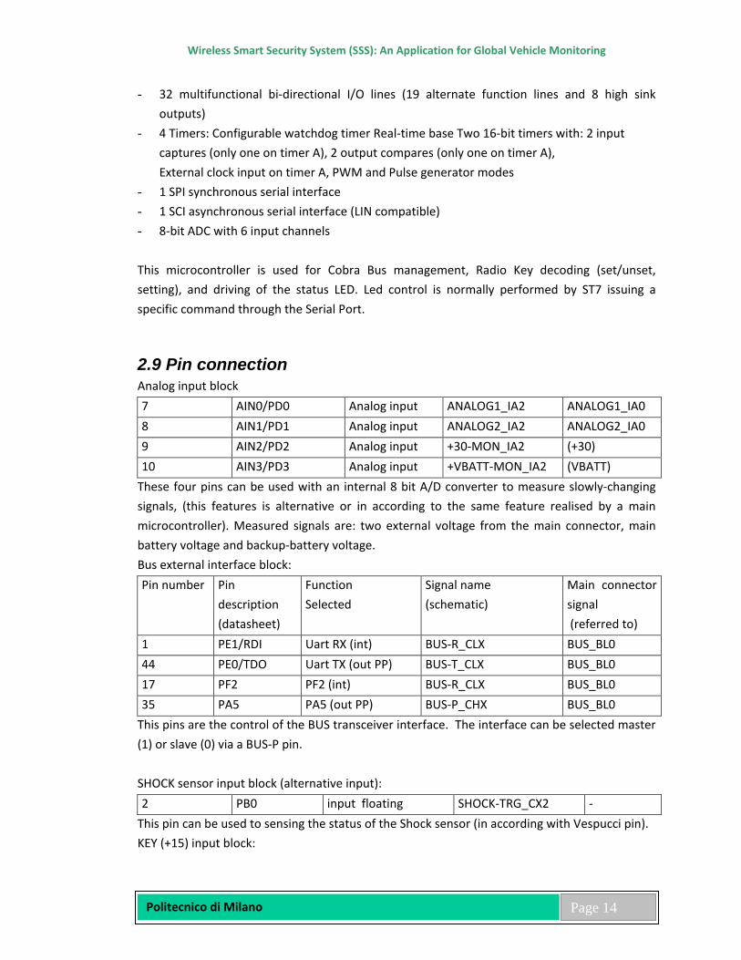
- 32 multifunctional bi-directional I/O lines (19 alternate function lines and 8 high sink outputs)
- 4 Timers: Configurable watchdog timer Real-time base Two 16-bit timers with: 2 input captures (only one on timer A), 2 output compares (only one on timer A), External clock input on timer A, PWM and Pulse generator modes
- 1 SPI synchronous serial interface - 1 SCI asynchronous serial interface (LIN compatible) - 8-bit ADC with 6 input channels This microcontroller is used for Cobra Bus management, Radio Key decoding (set/unset, setting), and driving of the status LED. Led control is normally performed by ST7 issuing a specific command through the Serial Port.
2.9 Pin connection Analog input block 7 AIN0/PD0 Analog input ANALOG1_IA2 ANALOG1_IA0 8 AIN1/PD1 Analog input ANALOG2_IA2 ANALOG2_IA0 9 AIN2/PD2 Analog input +30-MON_IA2 (+30) 10 AIN3/PD3 Analog input +VBATT-MON_IA2 (VBATT)
These four pins can be used with an internal 8 bit A/D converter to measure slowly-changing signals, (this features is alternative or in according to the same feature realised by a main microcontroller). Measured signals are: two external voltage from the main connector, main battery voltage and backup-battery voltage. Bus external interface block: Pin number
Pin description (datasheet)
Function Selected
Signal name (schematic)
Main connector signal (referred to)
1 PE1/RDI Uart RX (int) BUS-R_CLX BUS_BL0 44 PE0/TDO Uart TX (out PP) BUS-T_CLX BUS_BL0 17 PF2 PF2 (int) BUS-R_CLX BUS_BL0 35 PA5 PA5 (out PP) BUS-P_CHX BUS_BL0
This pins are the control of the BUS transceiver interface. The interface can be selected master (1) or slave (0) via a BUS-P pin. SHOCK sensor input block (alternative input): 2 PB0 input floating SHOCK-TRG_CX2 -
This pin can be used to sensing the status of the Shock sensor (in according with Vespucci pin). KEY (+15) input block:
Wireless Smart Security System (SSS): An Application for Global Vehicle Monitoring
Politecnico di Milano
Page 15
3 PB1 Input floating +15P_IH1 +15_IH0 This pin is used to sensing the status of the KEY-Switch on the vehicle. Input has a voltage protection and pull-down resistor. State “1” means KEY (input +15) is ON. RadioKey reckoning input block: 6 PB4 interrupt floating RK-CODE_CH2 - 19 PF6/ICAP1_A ICAP1_A (int) RK-CODE_CH1 - 34 PA4 PA4 (out PP) RK-EN_CL2 - These pins interface the dedicated 433MHz RF module for Radio Key /Driver Card decoding. The pin RK-CODE use an interrupt input on radio receiver: transition 0 1 of pin means transmission frame to a Radiokey/DriverCard. The pin RK-EN is used for enable/disable the Radio receiver power supply (in according with controller pin). Normal state is “0” (radio receiver ON). State “1” means power supply is disabled. Output has an external pull-down resistor. Status LED and push-button interface block: 4 PB2 PB2 (int) LED-PUSH_IL1 LED-
PUSH_IL0 18 PF4/OCMP1_A OCMP1_A (out OD) LED_OL2 LED_OH0 23 PC0/OCMP2_B Input floating LED_ILX LED_OH0 This pin is used for control the diagnostic LED and emergency pushbutton interface. When LED is ON the Pushbutton status is unavailable. Input signal LED is used of ST7 to monitor LED status (especially used when LED is under control). Input signal LED-PUSH is used to monitor the status of external Pushbutton, following this table: Pin of ICD30
Function
Led status: OFF Led status: ON (under Vespucci control)
Led status: ON (under ST7 control)
Pushbutton status OFF ON If LED is ON pushbutton status is
unavailable LED_OL1 Out 1 1 1 0 LED_OL2 Out 1 1 0 1 LED_IL1 In 1 1 0 0 LED-PUSH _IL1 In 1 0 0 0
Communication block (ST7-Vespucci internal communication serial BUS) 24 PC1/OCMP1_B OCMP1_B (out PP) COM-RXD_CLX - 26 PC3/ICAP1_B ICAP1_B (input) COM-TXD_CL1 - 31 PA3 PB4 (int) COM-TXD_CL2 -

Wireless Smart Security System (SSS): An Application for Global Vehicle Monitoring
Politecnico di Milano
Page 16
These pins are reserved for a full-duplex asynchronous communication with a UART3 of controller. The pin 31 is reserved for interrupt input detect: transition 1 0 of pin means transmission from controller. Clock input/output block: 15 MCO/PF0 MCO (out PP 4MHz) MCO2_CXX - 41 OSC2 Resonator 8 MHz CKO2_CXX - 42 OSC1 Resonator 8 MHz CKI2_CXX -
These pins are used for oscillator (ceramic resonator 8MHz). The Master Clock Output (MCLK/2=4MHz) are available on controller instead the main oscillator, for reducing power consumption and costs. Intercommunication block (ST7 internal communication BUS) and ISP: 27 PC4/MISO/ISPDATA ISPDATA (input) ISP-DATA_BL0 ISP
connector 29 PC6/SCK/ISPCLK ISPCLK (int) ISP-CLK_BL0 ISP
connector 38 ISPSEL ISPSEL (input) ISP-SEL_IH0 ISP
connector 39 RESET RESET (input) ISP-RST_IL0 ISP
connector These pins are used for a In System Programming of ST7 The ISP feature is available also used an external device connected to a some pins of the Jtag programming connector (reserved pin for the in-circuit serial programming of the ST7 secondary microcontroller). State “1” of ISP-SEL pin, in according to a ST7-RESET pin, means ST7 is in program mode. Normal state of ISPselect mode pin is “0”. Normal state of reset pin is “1” (after reset). The ISP feature is also available from GSM-DTR, DIGITAL4, ISP-RST and ISP-SEL pins. In this case the auxiliary oscillator must be selected. Buzzer output blocks (alternative output): 36 PA6 Output OD BZZ_OL2 BZZ_OL0
This pin can be used to enable the BUZZER low side output driver (in according with Expander 1.5 pin). ST7unused pin: 5 PB3 - - - 11 AIN4/PD4 - - - 12 AIN5/PD5 - - - 16 BEEP/PF1 - - - 20 PF7/EXTCLK_A - - - 25 PC2/ICAP2_B - - -
Wireless Smart Security System (SSS): An Application for Global Vehicle Monitoring
Politecnico di Milano
Page 17
28 PC5/MOSI - - - 30 PC7/SS - - - 37 PA7 - - -
These pins are unused/unconnected. No pull-up/pull-down is present. Select these pin as a input with internal pull-up or output open-drain with "1" state.
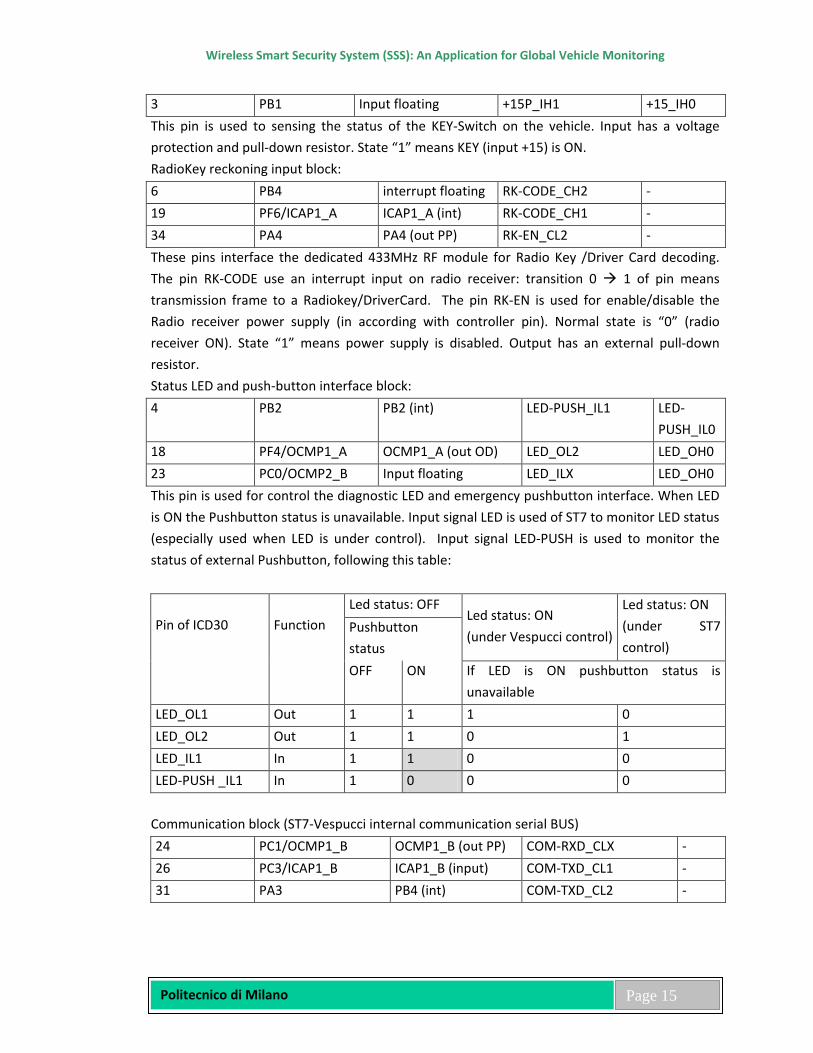
2.10 External Connection Block Diagram
Figure 4: External Connection of the system
2.11 GPS block The system is equipped with a U-blox TIM-LC GPS receiver to detect the vehicle position. In order to reduce power consumption, this module and GPS antenna are switched-on when necessary, under software control.
Wireless Smart Security System (SSS): An Application for Global Vehicle Monitoring
Politecnico di Milano
Page 18
The GPS module is connected to micro through a dedicated serial port. A secondary NMEA protocol port of the GPS module is available at RS232 physical level on the main connector (this function must be configured by software). An antenna connection detection feature is implemented. This allows the system to check that the antenna is properly connected.
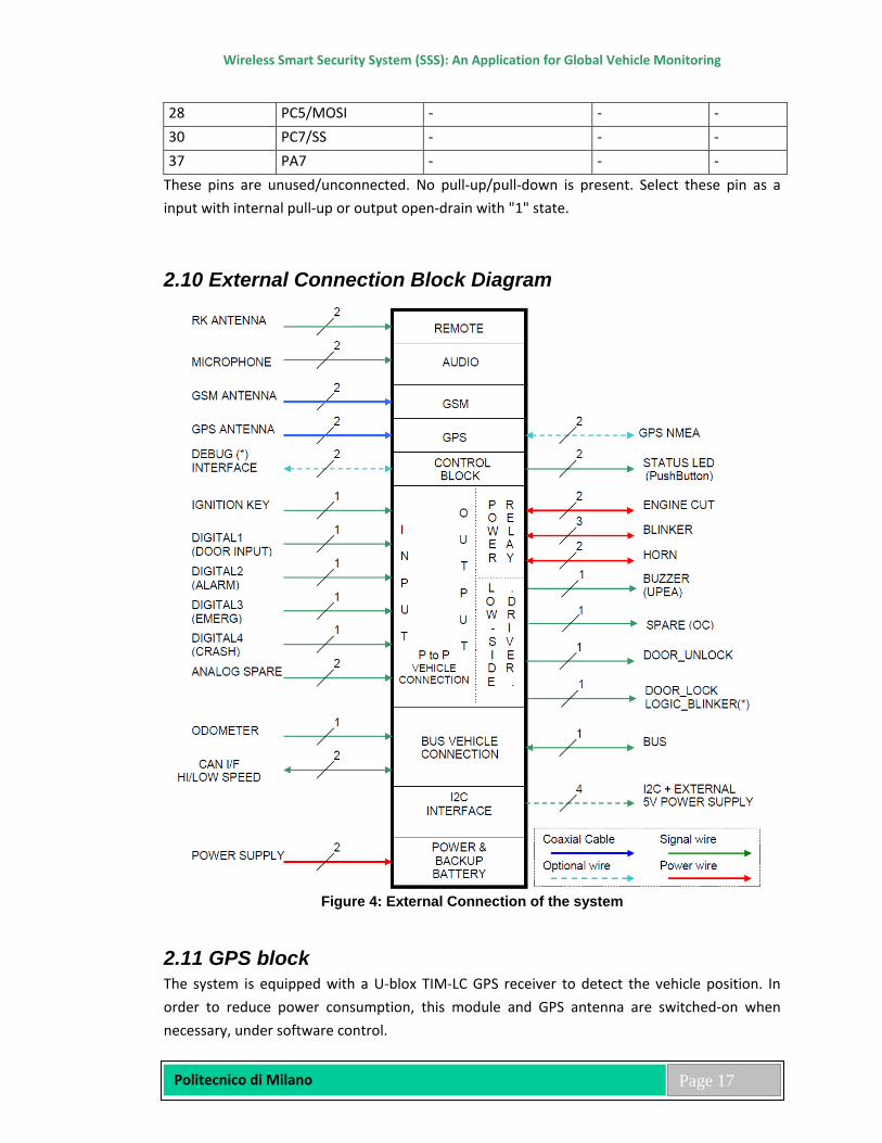
Figure 5: Basic Signal Processing
The processing steps involved are: 1. RF Section In the RF Section the GPS signal detected by the antenna is amplified, filtered and converted to an intermediate frequency (IF). An A/D converter changes the analog intermediate frequency into a digital IF signal. 2. GPS Channels The digital IF signal bit stream is passed to the base band section, where it is fed into the correlators. It is the function of the correlators to acquire and track the satellite signals. There are 16 channels used in parallel, with each correlator looking for a characteristic PRN code sequence in the bit stream. Once the correlator has a valid signal, Pseudorange, Carrier Phase and Orbit Information can be extracted from the GPS signal. 3. Navigation The on-board processor is running an algorithm that calculates the position, velocity and time. This calculation is called the navigation solution. Once the navigation solution is calculated, it can be transformed into the desired coordinate system, e.g. Latitude/ Longitude/ Altitude. 4. Interface The data of the navigation solution is available at the serial RS232 interface. When the receiver is powered up, it steps trough a sequence of states until it can initially determine position, velocity and time. Afterwards, the satellite signals are tracked continuously and the position is calculated periodically.
Wireless Smart Security System (SSS): An Application for Global Vehicle Monitoring
Politecnico di Milano
Page 19
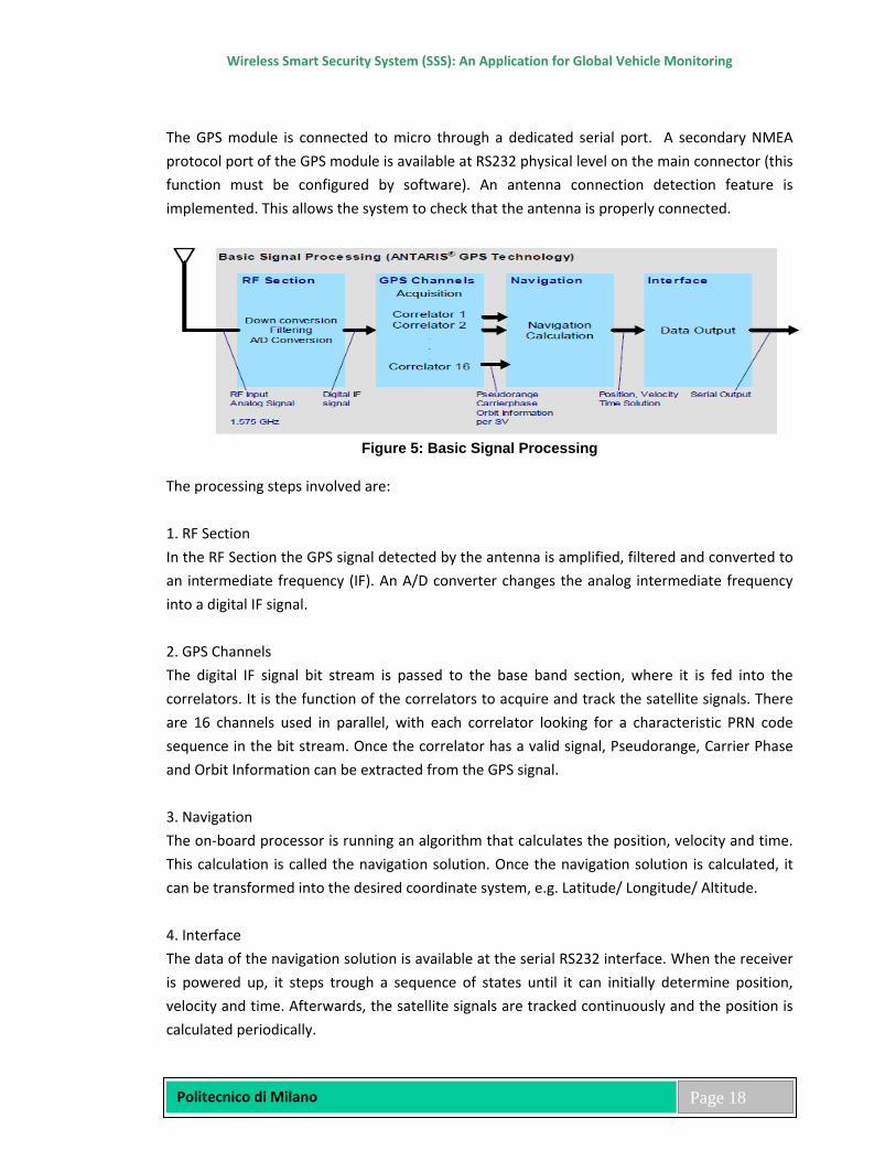
This process is depicted below:
Figure 6: Basic Signal Processing of GPS module
The initial position calculation is made using a Least-Squares Algorithm. Successive position calculations are performed with a Kalman Filter. To generate a Position (3D solution) Calculation the receiver needs at least 4 measurements to different satellites, to calculate a position (Lat/Long/Height), for a 2D solution with an estimated altitude 3 different satellites are required. Pseudo Range and Carrier Phase information is available to the Position Determination Algorithms if the receiver has found a SV (Acquisition) and can track the signal thereafter. Ephemeris data for a SV can be decoded from Orbit Data once the GPS signal has been acquired. Each SV transmits its own ephemeris data, the broadcast lasts for 18 seconds, repeating every 30 seconds. The receiver stores ephemeris data in battery-backed memory. This data is valid for 2 hours and can be used in future startup’s to improve the time to first fix (TTFF). Ephemeris can also be supplied to the receiver via the serial port.
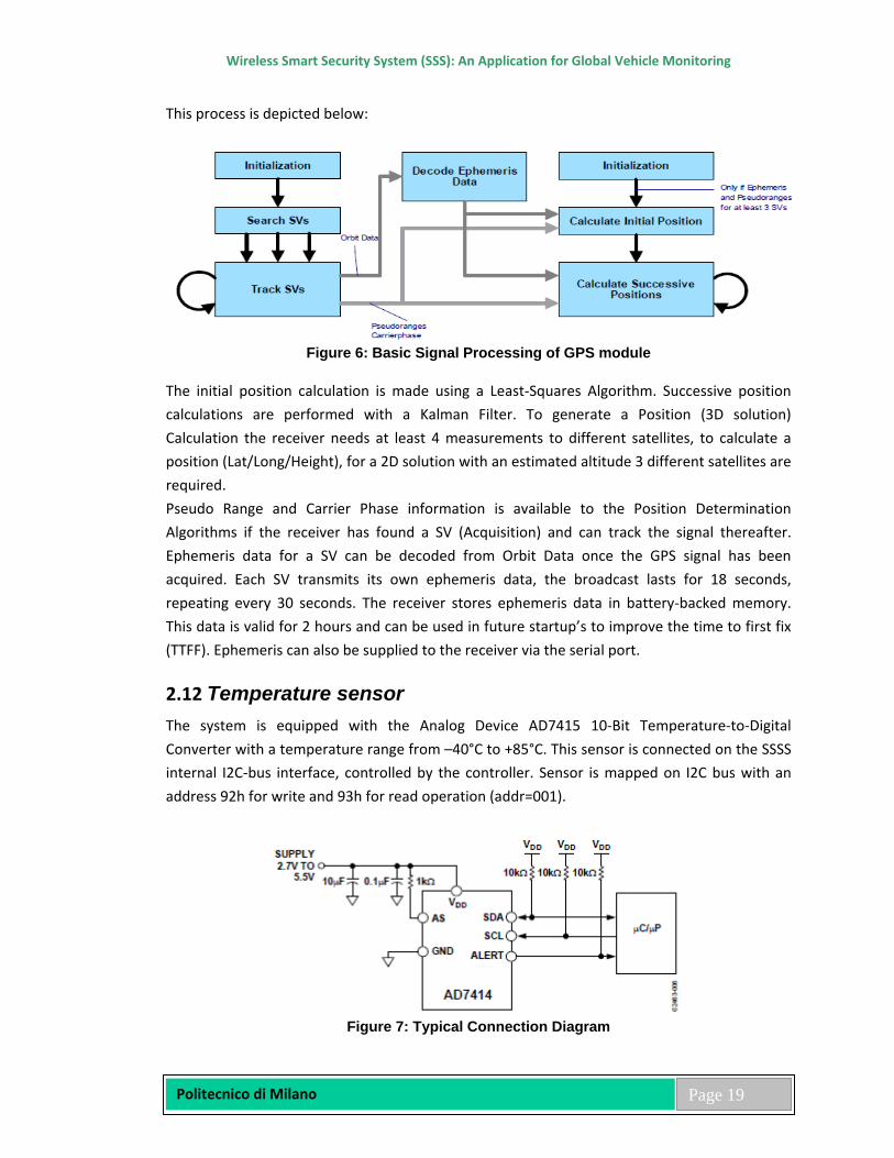
2.12 Temperature sensor The system is equipped with the Analog Device AD7415 10-Bit Temperature-to-Digital Converter with a temperature range from –40°C to +85°C. This sensor is connected on the SSSS internal I2C-bus interface, controlled by the controller. Sensor is mapped on I2C bus with an address 92h for write and 93h for read operation (addr=001).
Figure 7: Typical Connection Diagram
Wireless Smart Security System (SSS): An Application for Global Vehicle Monitoring
Politecnico di Milano
Page 20
Temperature measurement is initiated by two methods. The first uses an internal clock countdown of 800 ms, and a conversion is performed. The internal oscillator is the only circuit that is powered up between conversions, and once it times out, every 800 ms, a wake-up signal is sent to power up the rest of the circuitry. A monostable is activated at the beginning of the wake-up signal to ensure that sufficient time is given to the power-up process. The monostable typically takes 4 μs to time out. It then takes typically 25 μs for each conversion to be completed. The new temperature value is loaded into the temperature value register and ready for reading by the I2C interface.
A temperature measurement is also initiated every time the one-shot method is used. This method requires the user to write to the one-shot bit in the configuration register when a temperature measurement is needed. Setting the one-shot bit to 1 starts a temperature conversion directly after the write operation. The track-and-hold goes into hold approximately 4 μs (monostable time out) after the STOP condition, and a conversion is then initiated. Typically 25 μs later, the conversion is complete and the temperature value register is loaded with a new temperature value.
The measurement modes are compared with a high tempera-ture limit, stored in an 8-bit read/write register. This is applicable only to the AD7414, because the AD7415 does not have an ALERT pin and subsequently does not have an over temperature monitoring function. If the measurement is greater than the high limit, the ALERT pin is activated (if it has already been enabled in the configuration register). There are two ways to deactivate the ALERT pin again: when the alert reset bit in the configuration register is set to 1 by a write operation, and when the temperature measured is less than the value in the TLOW register.
2.13 CAN interface The system has a unique CAN physical interface enabled to manage High speed and low speed, CAN interface is implemented using a fault-tolerant physical bus transceiver, primarily intended for High-speed applications up to 1MBaud in passenger cars. Main feature of High speed CAN interface are: • Fully compatible with the ISO 11898 standard • High speed (up to 1MBaud) • Very low-current standby mode with remote wake-up capability via the bus • Very low Electro Magnetic Emission (EME) • Differential receiver with high common-mode range for Electro Magnetic Immunity (EMI) • Transceiver in unpowered state disengages from the bus (zero load) • Input levels compatible with 3.3 V and 5 V devices • Voltage source for stabilizing the recessive bus level if split termination is used (further
improvement of EME)
Wireless Smart Security System (SSS): An Application for Global Vehicle Monitoring
Politecnico di Milano
Page 21
• At least 110 nodes can be connected • Transmit Data (TXD) dominant time-out function • Bus pins protected against transients in automotive environments • Bus pins and pin SPLIT short-circuit proof to battery and ground • Thermally protected.
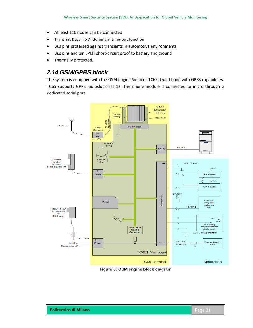
2.14 GSM/GPRS block The system is equipped with the GSM engine Siemens TC65, Quad-band with GPRS capabilities. TC65 supports GPRS multislot class 12. The phone module is connected to micro through a dedicated serial port.
Figure 8: GSM engine block diagram
Wireless Smart Security System (SSS): An Application for Global Vehicle Monitoring
Politecnico di Milano
Page 22
2.15 I2C interface I2C interface is implemented using a I2C bus transceiver. Messages on this bus are received and managed by I2C core embedded on the controller. This interface normally is accessible from the main connector in according to a I2C-ENA pin of controller. I2C Communication Procedure One IC that wants to talk to another must: 1) Wait until it sees no activity on the I2C bus. SDA and SCL are both high. The bus is 'free'. 2) Put a message on the bus that says ‘its mine’ - I have STARTED to use the bus. All other ICs then LISTEN to the bus data to see whether they might be the one who will be called up (addressed). 3) Provide on the CLOCK (SCL) wire a clock signal. It will be used by all the ICs as the reference time at which each bit of DATA on the data (SDA) wire will be correcting (valid) and can be used. The data on the data wire (SDA) must be valid at the time the clock wire (SCL) switches from 'low' to 'high' voltage 4) Put out in serial form the unique binary 'address' (name) of the IC that it wants to communicate I with. 2 5) Put a message (one bit) on the bus telling whether it wants to SEND or RECEIVE data from the other chip. 6) Ask the other IC to ACKNOWLEDGE (using one bit) that it recognized its address and is ready to communicate. 7) After the other IC acknowledges all is OK, data can be transferred. 8) The first IC sends or receives as many 8-bit words of data as it wants. After every 8-bit data word the sending IC expects the receiving IC to acknowledge the transfer is going OK.
2.16 LED indicator The system will indicate its actual state by means of various modes of blinking diode. In particular, the LED state can be: Off When the system is in UNLOCK or INACTIVE status; On When the system is performing initialization procedure; Fast blink When the system is in WATCH mode, i.e. the car has been secured; Fixed On When an error occurred during initialization phase; e.g. the SIM card has not
been inserted, or the GSM module is not working properly. This LED is normally driven by the main microcontroller, except while it enters the sleep mode, in which case it will be driven by the secondary one.
2.17 Input/Output The system has a various sensor/actuator interface available on the main connector:
Wireless Smart Security System (SSS): An Application for Global Vehicle Monitoring
Politecnico di Milano
Page 23
- Four “static” inputs: These inputs can accept a ground connection or a voltage connection. These inputs have a default pull-up configuration, pull-down are possible changing the part list. All these input are interrupts.
- Two Analog inputs (range 0V to 30V) for external analog sensor connection. These input are monitored by controller each 3 sec. when Ignition is on and by the ST7 when ignition is off. ST7 detect a variation on these input and wake-up the controller that do the voltage acquisition
- Six low side outputs (1,5A output sink current), used for door lock, door unlock, buzzer (Upea) and the 3 additional outputs are reserved for future purposes.
- One double Relay to drive blinker (12V/24V switch signal: +30BLK, BLK1, BLK2) One relay for Engine LOCK (Com and NO)
- One relay for HORN or SIREN (Com and NO) - Dedicated Ignition KEY input (+15) - Dedicated ODOMETER pulse input.
2.18 Audio interface The GSM/GPRS module has an audio connection for silent-listening feature in case of theft.
• Two wire for 5V active microphone
2.19 Remote key Interface The ST7 microcontroller interfaces the Remote Key Control Unit by means of dedicated 433MHz RF module. The system can recognize a maximum of 4 different Remote Key Control Units. When the system is put in learning mode all previously learnt keys will be lost, and desired keys have to be learnt again. The START and END LEARNING PHASES are triggered by the controller, as a consequence of specific external commands (i.e. SMS messages).
2.20 DriverCard The ST7 microcontroller interfaces the Driver Card Unit by means of dedicated 433MHz RF module.The system can recognize a maximum of 4 different Driver Card Units. When the system is put in learning mode all previously learnt Driver Card will be lost, and desired Driver Card have to be learnt again. The START and END LEARNING PHASES are triggered by the controller, as a consequence of specific external commands (i.e. SMS messages).
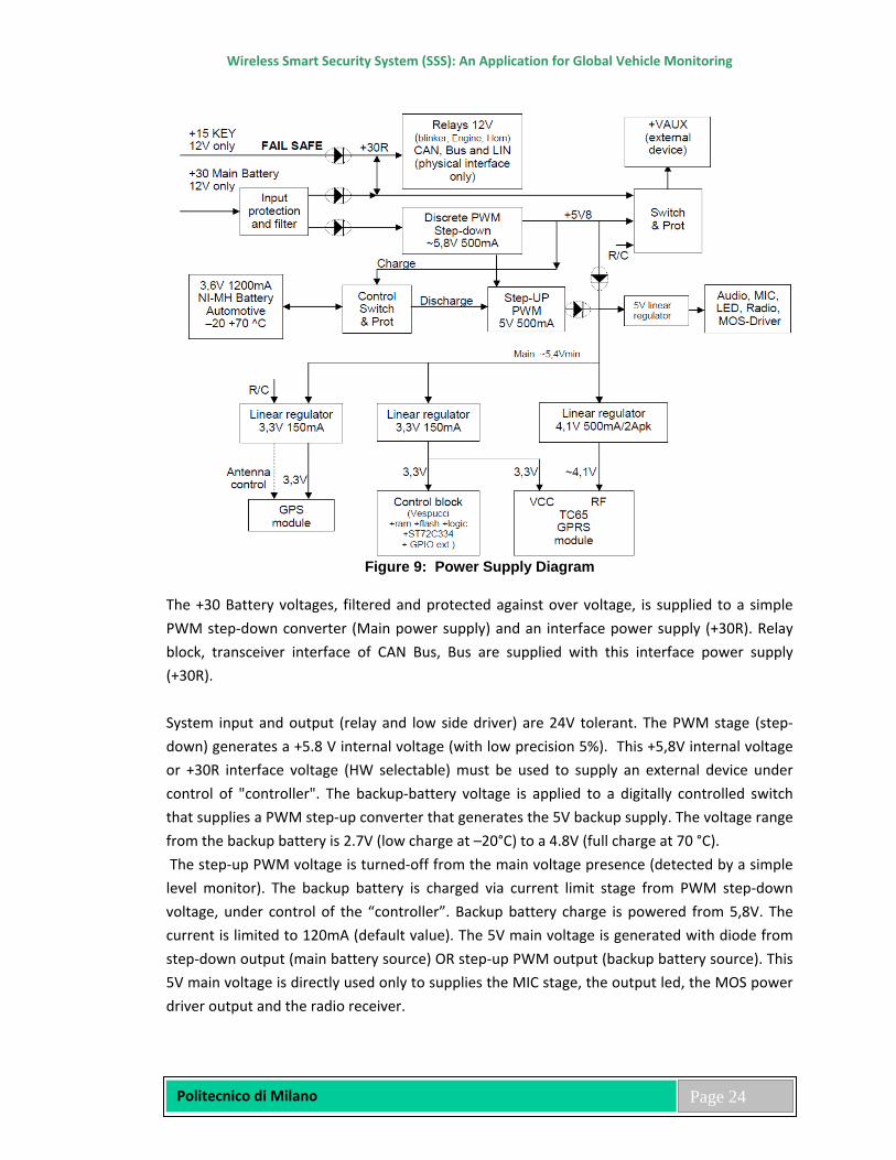
2.21 Power Stage The Power Supply stages are reported in the following diagram:
Wireless Smart Security System (SSS): An Application for Global Vehicle Monitoring
Politecnico di Milano
Page 24
Figure 9: Power Supply Diagram
The +30 Battery voltages, filtered and protected against over voltage, is supplied to a simple PWM step-down converter (Main power supply) and an interface power supply (+30R). Relay block, transceiver interface of CAN Bus, Bus are supplied with this interface power supply (+30R). System input and output (relay and low side driver) are 24V tolerant. The PWM stage (step-down) generates a +5.8 V internal voltage (with low precision 5%). This +5,8V internal voltage or +30R interface voltage (HW selectable) must be used to supply an external device under control of "controller". The backup-battery voltage is applied to a digitally controlled switch that supplies a PWM step-up converter that generates the 5V backup supply. The voltage range from the backup battery is 2.7V (low charge at –20°C) to a 4.8V (full charge at 70 °C). The step-up PWM voltage is turned-off from the main voltage presence (detected by a simple level monitor). The backup battery is charged via current limit stage from PWM step-down voltage, under control of the “controller”. Backup battery charge is powered from 5,8V. The current is limited to 120mA (default value). The 5V main voltage is generated with diode from step-down output (main battery source) OR step-up PWM output (backup battery source). This 5V main voltage is directly used only to supplies the MIC stage, the output led, the MOS power driver output and the radio receiver.
Wireless Smart Security System (SSS): An Application for Global Vehicle Monitoring
Politecnico di Milano
Page 25
The digital part of the board, the GPS and the GSM/GPRS modules has a dedicated linear regulator: • The main microcontroller STA2051, the RAM, the Flash memory, the glue logic, the
secondary microcontroller ST72C334J, the GPIO ext. and the backed-up RAM of the GPS module are powered via a low drop 3,3V linear regulator.
• The GPS module and the GPS active external antenna are powered via a low drop 3,3V linear regulator controlled by a “controller” I/O pin.
• The GSM/GPRS RF part are powered via a low drop 4.1V linear regulator with 2A peak power capability.
Wireless Smart Security System (SSS): An Application for Global Vehicle Monitoring
Politecnico di Milano
Page 26
Chapter 3
Software Designing, Debugging and Programming The Software Design Document is a specification which is used to aid in software development by providing the details for how the software should be built. Within the Software Design Document there is narrative and graphical documentation of the software design for the project including use case models, sequence diagrams, collaboration models, object behavior models, and other supporting requirement information. This document provides a comprehensive architectural overview of the system. It is intended to capture and convey the significant architectural decisions that have been made on the system. Aim of this software design for the microcontroller unit of the system.
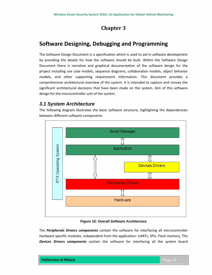
3.1 System Architecture The following diagram illustrates the basic software structure, highlighting the dependencies between different software components
Figure 10: Overall Software Architecture
The Peripherals Drivers components contain the software for interfacing all microcontroller hardware specific modules, independent from the application: UARTs, SPIs, Flash memory, The Devices Drivers components contain the software for interfacing all the system board
Wireless Smart Security System (SSS): An Application for Global Vehicle Monitoring
Politecnico di Milano
Page 27
hardware specific devices, independent from the application: GSM module, GPS module, The RTX RTOS component contains the operating system software modules. The Application components contain the software modules responsible of the functionalities of the system. Operating system tasks are defined at this level, as well as all interface control modules that depends on the low level drivers. Modules in this layer are able to activate tasks, send events or handle operating system resources. Examples are: the object that has in charge the handling of the accelerometer services, the object that has in charge the handling of the GSM services and of the client/server communication protocol. The Application includes also the Script Manager task able to decode and execute the Script instructions.
3.2 System Interfaces The software is needed to interface with the GSM Module to send commands and receive answers and events notification from it. The connection is standard serial communication. The software need to interface with the GPS Module to configure it and receive navigation data. The connection is a standard serial communication. Here are the applications of software’s: → The software will need to interface with a Radio Frequency 2.4 GHz Input/Output Controller to handle a RF 2.4 GHz Network. → The software will need to handle a Backup Battery Module for power the system in case of Main Battery disconnection. → The software will need to interface a 3 Axes Accelerometer for capturing data information relating to the vehicle way usage. → The software will need to interface a SPI Flash memory for data storage. → The software will also need to interface with an external device (i.e. a standard PC) to allow system test and debug. →The connection will be via a serial communication line.
3.3 Debugging and Programming The system provides different features for debugging and upgrading purposes. A connector is present on the bare board to allow the connection of an In-Circuit Emulator like Multi-ICE to perform source code analysis and debugging. Some pins on this same physical connector are reserved for the in-circuit serial programming of the ST7 secondary microcontroller. Programming of ST7 will be performed by means of specific code running on the controller. A “debug” serial port is accessible on the main connector to allow different on-field operations. This serial port is used for factory first-level boot loader programming, and for downloading and upgrading of application software and configurable parameters.

Wireless Smart Security System (SSS): An Application for Global Vehicle Monitoring
Politecnico di Milano
Page 28
First time programming of controller boot loader is based on ST-proprietary software embedded on the microcontroller, named TestFlash. To activate this internal feature, a special Boot Enable mode must be activated by connecting the GPS-RXD input pin of the main connector to a +30 (Vbatt) voltage before power on.
Figure 11: Boot enables mode feature activation
3.4 System Initialization Sequence The following flow describes the SSS platform initialization sequence: /* Main Program */ int main(void) { /* Setup System Clock, PLL, Flash Configuration and Peripherals Clock */ setupClock(); /* Default Setup for GP I/O */ setupGPIO(); /* Initialize Battery Management I/O State, Step Up Regulator Activation, */ /* so the Backup Battery can power the system if needed */ batteryInitIO(); /* Setup FSMC */ /* External RAM Memory Controller Setup */ /* The selected External RAM device is the Cypress CY62157EV30LL */ /* 512 x 16, 8 Mbit, 1 Mbyte. */ setupFSMC(); /* Setup Nested Vectored Interrupt Controller */ setupNVIC();
Wireless Smart Security System (SSS): An Application for Global Vehicle Monitoring
Politecnico di Milano
Page 29
/* Initialize Analog Management -> */ /* moved into task1 function because it has to be called after OS start up */ /* analogInit(); */ /* Initialize RTC Module -> */ /* moved into task1 function because it has to be called after OS start up */ /* rtcInit(); */ /* Initialize TIMER 2 as 1 ms Time Base Timer */ timerInit(); /* Initialize Window Watchdog */ /* If the system enters STOP mode, the WWDG clock is stopped (WWDG timer */ /* frozen), so the WWDG can be enabled also when using STOP mode. */ wdgInit(); /* OS Start Up */ os_sys_init(task1); /* Infinite Loop - If OS started correctly we should never fall here. */ while (1) { } }
3.5 Drivers List The following table summarizes the software modules used for peripheral drivers implementation.
Module Name Files List Description Serial Interface serial.c/.h This module manages all the services for
receiving/transmitting operations on the UART asynchronous serial ports.
Timer Interface timer.c/.h This module manages all the services related to the time base control operations based on the TIMER 2 controller.
SPI Interface spi.c/.h This module manages all the services for receiving/transmitting operations on the SPI synchronous serial ports.
Wireless Smart Security System (SSS): An Application for Global Vehicle Monitoring
Politecnico di Milano
Page 30
Embedded Flash Memory Interface
flash.c/.h This module manages all the services for reading/writing operations on the embedded Flash memory.
Real Time Clock rtc.c/.h This module manages all the services related to the time base control operations based on the RTC.
Watchdog Timer wdg.c/.h This module manages all the services related to the watchdog system mechanism.
System and Low Power Mode Interface
system.c/.h This module manages all the services related to the system and low power mode handling,
Analog to Digital Converter Interface
adc.c/h This module manages all the services for the analog to digital conversion of the analog inputs.
Input/Output Interface gpio.c/.h This module manages all the services for reading /writing operations on inputs/outputs ports and pins.
CAN Bus Interface can.c/.h This module manages all the services for receiving messages on the CAN bus.
3.6 Serial Interface The device has 5 serial interfaces connected to the following lines:
1. UART1 SW Programming by Embedded ST Boot Loader, ICT Console and Shell Console (Internal Serial Line Interface 115200 Baud)
2. UART2 GSM/GPRS Module 3. UART4 GPS Module 4. UART5 (1 wire) EOL Console and SW Updating by SW Application and Bus
(External Serial Line Interface 115200 Baud) These functions aren’t threading safe. These functions are declared and defined in:
• serial.h – Definition file • serial.c – Declaration file
SerialPortSelector Definition
/* UART selector definition */ typedef enum { SERIAL_PORT1 = 0, SERIAL_PORT2, SERIAL_PORT3, SERIAL_PORT4, SERIAL_PORT5 } SerialPortSelector;
Wireless Smart Security System (SSS): An Application for Global Vehicle Monitoring
Politecnico di Milano
Page 31
/* Serial Port Word Length selector definition */
typedef enum { SERIAL_WORDLEN_8 = USART_WordLength_8b, SERIAL_WORDLEN_9 = USART_WordLength_9b } SerialWordLenSelector; /* Serial Port Stop Bits selector definition */ typedef enum { SERIAL_STOPBITS_1 = USART_StopBits_1, SERIAL_STOPBITS_0_5 = USART_StopBits_0_5, SERIAL_STOPBITS_2 = USART_StopBits_2, SERIAL_STOPBITS_1_5 = USART_StopBits_1_5 } SerialStopBitsSelector; /* Serial Port Parity selector definition */ typedef enum { SERIAL_PARITY_NO = USART_Parity_No, SERIAL_PARITY_EVEN = USART_Parity_Even, SERIAL_PARITY_EVEN = USART_Parity_Even } SerialParitySelector;
3.7 Embedded Flash Memory Interface These functions must verify that the memory isn’t busy by a write or an erase before carrying out any other operations. It is not required that these functions are threading safe, also if it would be recommended. These functions are declared and defined in:
• flash.h – Definition file • flash.c – Declaration file
The flash.h file includes the following defines: • FLASH_MAX_WRBUFF_SIZE=2048 (buffer doesn't really exist but defined 2 Kbytes
anyway) • FLASH_MAX_PAGE_SIZE=2048 (2 Kbytes max page size) • FLASH_SIZE=0x80000 (embedded Flash memory total size) • FLASH_DATA_START_ADDR=0x08000000 (starting address of the embedded Flash
memory)
Wireless Smart Security System (SSS): An Application for Global Vehicle Monitoring
Politecnico di Milano
Page 32
This driver uses a low level driver (stm32f10x_flash.c) that must have its “_FLASH_PROG” label defined; moreover all its routines included within the “_FLASH_PROG” definition have been declared to be executed in RAM. The linker/scatter file includes a RAM area dedicated to RAM executed functions. This means that the main codes for Flash memory erasing and writing is allocated and executed in RAM. The erase and write functions lock and unlock the interrupts during execution. Due to a reduced watchdog timing window (low watchdog timeout expiration), the erase and write lowest level functions, executed in RAM, must refresh the watchdog timer. Embedded Flash Memory Endurance: 10,000 cycles. FlashInfoStruct Structure
typedef struct { u32 writeBaseAddress; /* base address useful for writing */ u32 eraseBaseAddress; /* base address useful for page erasing */ u32 writeBufferSize; /* size useful for writing */ u32 memoryPageSize; /* size useful for erasing (memory page size) */ u16 WriteableBytesUnit; /* minimum amount of bytes to write */ } FlashInfoStruct;
3.8 Input/Output Interface Relating to the external I/O connector pins the system foresees two hardware configurations:
• with CAN – 1 Digital Input / Digital Output • without CAN – 2 Digital Inputs / Digital Outputs + 1 Analog / Digital Input
o CAN-L only Analog / Digital Input The input pin connector is directly connected both to a microcontroller digital input and to a microcontroller analog input.
o CAN-H Digital Input / Output These functions aren’t threading safe. These functions are declared and defined in:
• gpio.h – Definition file • gpio.c – Declaration file
There is no need for the software to disable interrupts when programming the GPIOs at bit level: it is possible to modify only one or several bits in a single atomic write access (read/modify/write operation). All the digital inputs are programmed and treated like interrupts and Stop Mode wake up events. GPIOs Definition
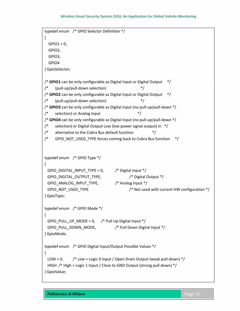
Wireless Smart Security System (SSS): An Application for Global Vehicle Monitoring
Politecnico di Milano
Page 33
typedef enum /* GPIO Selector Definition */ { GPIO1 = 0, GPIO2, GPIO3, GPIO4 } GpioSelector; /* GPIO1 can be only configurable as Digital Input or Digital Output */ /* (pull-up/pull-down selection) */ /* GPIO2 can be only configurable as Digital Input or Digital Output */ /* (pull-up/pull-down selection) */ /* GPIO3 can be only configurable as Digital Input (no pull-up/pull-down */ /* selection) or Analog Input */ /* GPIO4 can be only configurable as Digital Input (no pull-up/pull-down */ /* selection) or Digital Output Low (low power signal output) in */ /* alternative to the Cobra Bus default function */ /* GPIO_NOT_USED_TYPE forces coming back to Cobra Bus function */ typedef enum /* GPIO Type */ { GPIO_DIGITAL_INPUT_TYPE = 0, /* Digital Input */ GPIO_DIGITAL_OUTPUT_TYPE, /* Digital Output */ GPIO_ANALOG_INPUT_TYPE, /* Analog Input */ GPIO_NOT_USED_TYPE /* Not used with current HW configuration */ } GpioType; typedef enum /* GPIO Mode */ { GPIO_PULL_UP_MODE = 0, /* Pull Up Digital Input */ GPIO_PULL_DOWN_MODE, /* Pull Down Digital Input */ } GpioMode; typedef enum /* GPIO Digital Input/Output Possible Values */ { LOW = 0, /* Low = Logic 0 Input / Open Drain Output (weak pull-down) */ HIGH /* High = Logic 1 Input / Close to GND Output (strong pull-down) */ } GpioValue;

Wireless Smart Security System (SSS): An Application for Global Vehicle Monitoring
Politecnico di Milano
Page 34
typedef enum /* GPIO Configuration Structure Definition */ { GpioType type; /* External Connector Pin Type Setting */ /* (Digital Input, Digital Output, Analog Input) */ GpioMode mode; /* Required Digital Input Mode(Pull-up/Pull-Down) */ GpioValue outVal; /* Required Digital Output Value */ u16 inDebounceTime; /* Required Digital Input Debouncing Time in ms */ } GpioConfiguration;
Wireless Smart Security System (SSS): An Application for Global Vehicle Monitoring
Politecnico di Milano
Page 35
CHAPTER 4 Functionalities Description In the following chapters are described the functionalities related to FW 4.1 Alerts An alert is an event detected inside the system that is converted in a SMS format according with the “system Protocol”. The SMS format for all the alert conditions includes the fields of the Reply Data: vehicle battery level, detection system status, total distance covered, engine status, GSM signal level, engine startup authorization, navigation data, sensor 1 value, sensor 2 value, engine total running time. The system module updates and compiles all these fields before sending the SMS alert to the Server.
4.2 shk - Shock Detection Alert with System Set (Shock Dissuasion Sequence) Shock sensor Threshold 1 reached. The shock sensor Threshold 1 sensitivity can be programmed or can be put in off state. Alert is sent to the server and just after horn (1 s. fixed time enable/disable) and Blinker (20 s. fixed times Enable/disable) are activated. Shk event detection has a time limitation of 1 alert per minute max.
4.3 int – Intrusion Alert with System Set (Theft Sequence) Bus Module detects an intrusion, parametric Sensor 2, wrong PIN/Override Codes. Initially provided to notify intrusion due external module triggering, the name “int” has been adopted also for other alarm condition no more related to external modules events (e.g. parametric Sensor 2, wrong Override Code) Siren & Blinker are activated by the protocol, system sends an alert to the server and starts a theft tracking if theft sequencer is enabled & theft tracking mask protocol bit is set. int event detection has a time limitation of 1 alert per minute max. DOOR_OPEN_TIME parameter is used to set up a (0-25.5s) delay in case one of the following conditions is active:
• Bus External Master Module • DC learnt
4.4 mot - Vehicle Motion Alert with System Set (Theft Sequence) Movement detection (see mot Alert): 4 consecutive times of speed greater than 10 Km/h after 3 valid GPS fixes. Speed is measured by the GPS module using at least 4 satellites. SSS receives a GPS positioning every 8 s.; it is needed minimum 1 min. for vehicle movement detection. Actions will be performed in the following order: an Alert is sent to the server, Theft Dissuasion
Wireless Smart Security System (SSS): An Application for Global Vehicle Monitoring
Politecnico di Milano
Page 36
sequence is started (Blinker + Horn or siren in case of GLOBE (4xxx)), a theft tracking is started if theft sequencer is enabled and if corresponding theft tracking mask bit is set. mot event detection has a limitation of 1 alert per Movement Detection Phase (Key On or GPS Waked Up) to avoid a lot of alerts when the SSS is installed without engine lock.
4.5 mot - Vehicle Motion Alert with System Unset (Theft Sequence) (TNO normative) Ignition key off and vehicle in movement (movement detection like system set). This feature can be enabled or disabled using user profile command. Horn & Blinker are activated, an alert is sent to the server and a theft tracking is started if theft sequencer is enabled & theft tracking mask MOVEMENT bit is setSame as system set.
4.6 mOt - AutoZone Vehicle Motion Alert (Theft Sequence) This function has been added to comply with the thatcham normative concerning the motion detection (100 meters). This function is independent of Zone in/out functionalities; both functionalities (AutoZone and classical zone in/out) can be used at the same time. Each time the ignition key is switched off and a delay is elapsed, SSS stores the current vehicle position if the following conditions are present:
- GPS position fresh (after 3 valid GPS fixes) AND
- The last 5 consecutive GPS fixes (acquisitions) are valid positions (good valid fixes) AND
- Transport Mode Disabled AND
- Garage Mode Disabled AND
- AutoZone function enabled (Using the Set User Profile Server command)
If these conditions are not present SSD waits a GPS_WAKEUP event to retry this operation. The current position stored is called “reference position” and is composed by latitude & a longitude (ref_lat & ref_long). Using this reference position SSS automatically defines a zone using the Delta_lat & Delta_long parameters: [ref_lat – Delta_lat ; ref_lat + Delta_lat] [ref_long – Delta_long ; ref_long + Delta_long] note: Delta_lat & Delta_long parameters can be changed using the Set User Profile Server command. Once this zone is defined and if system is armed or disarmed with the movement
Wireless Smart Security System (SSS): An Application for Global Vehicle Monitoring
Politecnico di Milano
Page 37
detection at system unset function enabled, SSS performs the following sequence on each GPS acquisition:
- Counts how many consecutive positions are found outside this zone. - Transmits to the server a “mOt” alert when this counter reaches the predefined
threshold value + 1 and then froze the counter. - If current position is inside the AutoZone, the counter is cleared and unfrozen. - If no shock events are detected while performing the counting operation, counter is
cleared. The sequence is not executed if Garage Mode is ON or if Transport Mode is ON or if AutoZone Function is disabled. The threshold can be changed using the Set User Profile Server Command Parameters added in the SET_USER_COMMAND server command + PAR_ENABLE_AUTOZONE (default ="y") + PAR_AZ_DELTALAT (default="010" # 100 meters) + PAR_AZ_DELTALONG (default="010" # 100 meters) + PAR_AZ_THRESHOLD (default="2") Threshold= 02 (=> 3 consecutives measures outside the zone are needed to activate the mOt alert). Server can know if the AutoZone function is armed and is running by sending a query dat command and checking in the answer if the det field is in lower case or upper case. If this field is returned in upper case the AutoZone function is armed and is running. mOt event detection has a limitation of 1 alert per Movement Detection Phase (Key On or GPS Waked Up) to avoid a lot of alerts when the SSS is installed without engine lock. AutoZone function is also able to generate a mOt alert and to start the theft sequence when system is unset. This feature is called AutoZone system unset and it is intended to increase the security level for the rescue profiles (where the system is always unset). Note that TI is not possible to activate the function AutoZone system unset without activating the function AutoZone system set. To enable the function AutoZone system set and unset the following parameters must be configured: PAR_ENABLE_AUTOZONE=”y” PAR_ENABLE_MOVEMENT_DETECTION_SYSTEM_UNSET=’y’ To enable the function AutoZone system set only the following parameters must be configured: PAR_ENABLE_AUTOZONE=”y” PAR_ENABLE_MOVEMENT_DETECTION_SYSTEM_UNSET=’n’ To disable the function AutoZone the following parameter must be configured: PAR_ENABLE_AUTOZONE=”n”
Wireless Smart Security System (SSS): An Application for Global Vehicle Monitoring
Politecnico di Milano
Page 38
4.7 ign - Ignition Key On Alert with System Set (Theft Sequence) Ignition key (+15) on. Horn & Blinker are activated, an alert is sent to the server and a theft tracking is started if theft sequencer is enabled & theft tracking mask IGNITION bit is set ign event detection has a time limitation of 1 alert per minute max. A programmable delay from 100ms to 25.5s, is provided when SSS is operating with Driver Card, Bus Master Device. The delay must be sent to SSS from the server when at least one Driver Card has been learnt. The delay to be programmed is 12s-25s and must be set by a server command.
4.8 sab – Main Battery Tamper Alert with System Set (Theft Sequence) Main battery disconnection. SSS is powered by internal backup battery. An alert is sent to the server and a theft tracking is started if theft sequencer is enabled & theft tracking mask bit is set. Theft sequencer is not started in case of SSS Passive Armed. In case of main battery tamper event, for backup battery energy saving, SSS works as following:
• SSS System Set: GPS is waked-up ONLY when SSS needs to send a new theft tracking position (no GPS wake-up in case of shock or ignition key on), shock event is disabled
• SSS System Passive Armed: GPS is waked-up in case of shock or when SSS needs to send a new theft tracking position (no GPS wake-up in case of ignition key on); this because in passive arming the sab alert is not sent in control room, so the shock event has to stay alive
• Led is switched off • No Main Battery and No Backup Battery voltage measurement
4.9 sab – Main Battery Tamper Alert with System UnSet Main battery disconnection. SSS is powered by internal backup battery. No local alarms are activated. In Normal Mode and System Unset and Garage Mode Off only a sab alert is sent to the server and the Backup Battery maintains SSS powered during 3 hours minimum; after this time (3/4 hours) the system is automatically switched off (Backup Battery disconnection) if the Theft Tracking is Off. In First Installation Mode or Normal Mode and System Unset and Garage Mode On no sab alert is sent to the server and the system is automatically switched off (Backup Battery disconnection). In case of main battery tamper event, for backup battery energy saving, SSS works as following:
• SSS System Unset: GPS is waked-up in case of shock (if feature enabled) or when SSS needs to send a new theft tracking position (no GPS wake-up in case of ignition key on);
Wireless Smart Security System (SSS): An Application for Global Vehicle Monitoring
Politecnico di Milano
Page 39
this because in system unset the sab alert is not sent in control room, so the shock event has to stay alive.
• No Main Battery and No Backup Battery voltage measurement
4.10 lnb - Bus Tamper Alert with System Set (Theft Sequence) Connection with additional modules on bus is interrupted (Bus Cut). Siren & Blinker are activated and an alert is sent to the server and a theft tracking is started if theft sequencer is enabled & theft tracking mask BUS bit is set lnb event detection has a time limitation of 1 alert per minute max.
4.11 lnb - Bus Tamper Alert with System Unset Connection with additional modules on bus is interrupted. No theft sequence, just an alert is sent to the server lnb event detection has a time limitation of 1 alert per minute max
4.12 gps - GPS Antenna Sabotage Alert with System Set or UnSet GPS antenna disconnection/short circuit can be detected only if GPS is ON. No local alarms are activated, only an alert is sent to the server. GPS event detection is generated only when GPS On and when the previous antenna status was OK.
4.13 gpo - GPS Antenna Status OK Alert with System Set or UnSet GPS antenna status OK (recovery) can be detected only if GPS is ON. No local alarms are activated, only an alert is sent to the server. gpo event detection is generated only when GPS On and when the previous antenna status was NOT OK.
4.14 acc - Backup Battery Low Alert with system Set/Unset Backup battery is under a fixed threshold value 3.0 V (75% of 4.0 V). This alert can be disabled (user configuration). Backup battery is measured when the Ignition Key is turned off, one time per day. Acc event detection has a time limitation of 1 alert per day max. Because the backup battery level is measured one time per day to be sure to detect a low level could be necessary wait for 24 hours max. On/Off Backup Battery: normally the Backup Battery is On, it becomes Off when the Main Battery is disconnected at System Unset (Maintenance Phase); it comes back On when the Main Battery is reconnected (Maintenance Phase completed). Backup battery maintains alive the system during a tamper with system set. Backup battery is charged
Wireless Smart Security System (SSS): An Application for Global Vehicle Monitoring
Politecnico di Milano
Page 40
only with ignition Key ON at system unset. Backup battery measurements are performed using 7.2 / 255 = 0.028V ADC step size.
4.15 bat - Main Battery Low Alert with system Set/Unset Vehicle battery is under a programmable threshold value (default value 11 V). Retriggering is provided on a programmable value (default is 11,5 V). Vehicle battery is measured with the Ignition Key switched Off one time per day for 5 minutes. Battery low alert is sent if Main Battery Voltage is under a programmable threshold during 5 minutes. Bat event detection has a time limitation of 1 alert per day max. Because the main battery level is measured one time per day to be sure to detect a low level could be necessary wait for 24 hours max. Main battery measurements are performed using 48 / 255 = 0.188V ADC step size.
4.16 eng - Engine On/Off Alert with System Set/Unset Ignition key is switched on or off or both. The trigger conditions can be programmed using configuration command. eng event detection has a time limitation of 1 alert per minute max.
4.17 s1f & s1s - Sensor 1 Analog Input Alerts with System Set/Unset s1f & s1s events detection have a time limitation of 1 alert per minute max. Sensor 1 Analog input is read every 3 sec. Sensor 1 Analog input can be used in case of Hi-Jack Push Button installation: a manually operated switch forces the S1 input to GND level and provides also a resistor pull-up (3 wires switch). Sensor measurements are performed using 24 / 255 = 0.094V ADC step size.
4.18 s2d & s2u - Sensor 1 Digital Input Alerts (down, up) SSS sends an alert if voltage reaches the programmed condition (UP, DOWN, BOTH), alert can be deactivated putting this parameter to NONE. In passive arming mode this input is dedicated to sense the door opening and no alert can be generated. If any Clifford Mode is enabled this input is dedicated to Set/Unset SSS and can't be used to generate s2u, s2d alerts.
4.19 spd - Horizontal Speed Alert This function gives the possibility to program the reception of an alert if the pre-programmed speed limit is overtaken. For example, if you let someone borrow your vehicle, you are instantly alerted if the person overtakes the speed limit. The speed is measured by the GPS (maximum vehicle speed allowed = 320 km/h). The horizontal speed threshold for the alert detection is programmable. The Speed alert is generated when the vehicle speed overtakes the defined speed limit. A new alert of the same type will be generated only if the vehicle speed comes
Wireless Smart Security System (SSS): An Application for Global Vehicle Monitoring
Politecnico di Milano
Page 41
down the 7/ 8 of the defined speed limit and then overtakes again the limit. spd event detection has a time limitation of 1 alert per minute max. To avoid false speed alert notifications, the spd will be sent only after four consecutive measures higher than the threshold (40s delay) and if measures have been obtained using at least 4 satellites.
4.20 Zone In/Zone Out Alert (zin/zout) The SSS use top left and bottom right points (latitude and longitude) as the corners of the selected rectangle area. The zone can be disabled putting the two points to X value. When a zone is defined, the SSS checks the vehicle position compare it to the zone limits and send an alert when the vehicle exits out of or enters into the zone. It is possible program SSS to receive alert on zone in, zone out or both. zin/zout event detection has a time limitation of 1 alert per minute max.
4.21 Alert rk1 ÷ 4 USER Alerts When the system is Unset or Passive-Armed, user can send 4 pre-defined alerts using the Radio Key, according the table below:
- Button 1 + Button 5 (Send) = rk1 Alert - Button 2 + Button 5 (Send) = rk2 Alert - Button 3 + Button 5 (Send) = rk3 Alert (not available) - Button 4 + Button 5 (Send) = rk4 Alert (not available)
Each Alert can be enabled or disabled via Web application used to define user profile. The time limitation for each alert is of 1 per 10s. To inform the user that SSS receives successfully the user rkn (request to send), SSS turns Status LED On during 3s. rk4 alert is disabled if Additional Engine Lock capability is enabled.
4.22 cod Alert This alert is sent to the server each time the user enters 5 consecutive wrong Access Codes. This alert can be sent only if UPEA step 2 modes are enabled or if High Protection Time limitation for this alert is 1 per minute.
4.23 dcb Alert This alert is transmitted when the voltage of the Driver Card’s battery goes below a predefined threshold (edge detection). Time limitation for this alert is one alert max / day. Please note that alert is sent every day only if the Driver Card signal is received in the new day, otherwise will be sent only one time. Voltage Threshold can’t be changed by SSS.
Wireless Smart Security System (SSS): An Application for Global Vehicle Monitoring
Politecnico di Milano
Page 42
4.24 rkb Alert This alert is transmitted when the voltage of the Radio Key’s battery go below a predefined threshold. (Edge detection) Time limitation for this alert is one alert max / day. Please note that alert is sent every day only if the Radio Key signal is received in the new day, otherwise will be sent only one time. Voltage Threshold can’t be changed by SSS.
Wireless Smart Security System (SSS): An Application for Global Vehicle Monitoring
Politecnico di Milano
Page 43
CHAPTER 5
Event Descriptions
5.1 Initialization Event When the device is connected to power supply or when a reset is performed, the module first initializes itself and then sends an Initialization SMS. The message is sent using SMSC number stored in the SIM Card and the number of the Server according to the current module parameter settings. The message sends to the server information regarding the module: product name (“SSS” characters string as “family name”), circuit version, installed SIM ID number (if SIM Card ID number is different than 20 digit this field is filled with X), version of GPS firmware, version of GSM firmware, module status, last valid message id, product name, last reset condition, version of firmware module, module serial number, device connected to Bus. The SIM card phone number is transmitted to the server by the GSM network. In first installation mode SSS tries to send the init msg to the server (each 30 sec.) and only when it was able to transmit this msg (positive ack from TC65 GSM/GPRS module, no ack from the server) exits from this loop. Led is always on during this phase and flashes for each attempt of INIT msg transmission. In this phase SSS is able to accept parameter command to change server call number and SMSC number, all other commands are rejected. When Initialization phase is passed the led is switched off. In first installation mode SSS work in this way: • no alerts and no tracking events are generated • all received messages are processed • engine start-up is allowed • shock dissuasion is active • theft dissuasion is inactive When SSS is in normal mode it try to send INIT msg only one time. If the transmission is unsuccessfully this msg is stored in the SMS fifo (for future retry) if enabled, or loosen if SMS fifo is disabled.
5.2 User Programming Tracking Events Vehicle tracking is the capability of the SSS to communicate the vehicle position to the Server in the time. Tracking events can be considered periodic data sent by the SSS to the server via SMS. The tracking capabilities of the SSS are programmable, it is possible distinguish 2 types of tracking:

Wireless Smart Security System (SSS): An Application for Global Vehicle Monitoring
Politecnico di Milano
Page 44
a. Time Tracking, automatic, each xx minutes for yy hours b. Distance Tracking, automatic, each xx kilometers for yy hours
The Configuration Setup Command is foreseen to enable and to program the tracking modes a and b. The Tracking capability in term of time and distance are activated from the moment in which the command is received by the SSS. SSS does not send new position if it do not receive a new valid data from GPS module (GPS bad reception or switched off).
5.3 Theft Tracking Events Theft tracking is automatically started in case of theft event (according to theft tracking parameter, enable theft sequencer bit, theft tracking mask setting). Tracking can be divided in two steps: STEP 1 – High speed rate tracking. SS sends position every programmable xx sec. for yy programmable min. XX from 0 (disable) sec. to 2550 sec., at minimum step of 10 sec. (default 00 sec.) YY from 0 (disable) min. to 255 min., at minimum step of 1 min. (default 00 min.) During the first 15 min. GPS & main micro stay always On. After this time if:
• xx < 1 min - GPS and main micro stay On • 1 min. >= xx <= 10 min. - GPS and main micro are waked-up for fix 30 sec. before new
position sending (10 min. no GPS fix timeout) • xx > 10 min. – GPS and main micro are waked-up for fix 120 sec. before new position
sending (10 min. no GPS fix timeout) STEP 2 – Low speed rate tracking. SSS sends position every programmable xx min. for yy programmable hours. XX from 0 (disable) sec. to 255 min., at minimum step of 1 min. (default 00 min.) YY from 0 (disable) min. to 255 hours, at minimum step of 1 hour (default 00 hour) Please put XX greater than 10 min. GPS turned ON just during new position acquisition. During the first 15 min. GPS & main micro stay always On. After this time if:
• 1 min. >= xx <= 10 min. - GPS and main micro are waked-up for fix 30 sec. before new position sending (10 min. no GPS fix timeout)
• xx > 10 min. – GPS and main micro are waked-up for fix 120 sec. before new position sending (10 min. no GPS fix timeout)
Wireless Smart Security System (SSS): An Application for Global Vehicle Monitoring
Politecnico di Milano
Page 45
5.4 Theft Sequence Management
Theft Sequence is composed by Theft Dissuasion and Theft Tracking step 1 and 2. Theft Sequence (if enabled) can be started by the following events: • Tamper (sab) • Wrong Override Codes (int) • Ignition Key (ign) • Server (Theft Lock Command send by server independently of SSS state) • Movement (mot) • BUS Tamper (lnb) Each event can be authorized to also start a theft tracking by setting the right associated bit in theft tracking mask. Theft Dissuasion part is stopped: • Automatically at the end of the cycle when the original theft event disappears (exception is
made for Sensor 2 perimetric input) • Manually by user with the Radio Key or Driver Card • By the server Theft tracking can be only stopped by the server If SSS is in theft sequence no local/user generated events can restart it until completion of the entire cycle, only the server can do that. Theft Dissuasion Sequence is composed by blinker and horn
By default: 1. Horn = 9 cycles of 30 s. (one cycle is equal to 500ms. On, 500msec off for 25s. and 5
s. Off) 2. Blinkers = 500 ms. On, 500 ms. Off for 5 min.
5.5 Shock Sensor Management
Two different thresholds are used to manage shock sensor. The first one is programmable and used to trigger shk alert and start shock dissuasion sequence. The second one is used to wake up the GPS for 10 min. max. to make a fresh acquisition. The GPS WAKE UP mechanism use two thresholds:
- Normal Threshold - 2 seconds of continuous shock are needed to wake up the GPS - High Sensibility Threshold - any shock wakeup the GPS.
The number of GPS_WAKEUP generated using the high sensibility threshold is memorized in the variable GPS_WAKEUP_COUNTER. This variable is cleared every day or each time the ignition key is switched off. The GPS WAKE UP Mechanism use the high sensibility threshold only if GPS_WAKE_COUNTER < 6 AND System is SET or Passive Armed else the normal threshold is used.
Wireless Smart Security System (SSS): An Application for Global Vehicle Monitoring
Politecnico di Milano
Page 46
The number of “High Sensibility GPS Wake Up” is limited to 5/day or 5/parking period to optimise the power consumption of SSS and reduce risk to discharge the main battery in case of repetitive shocks.
For both the thresholds, the Shock Detection Function is off when Theft Dissuasion/Tracking Sequence is on or when horn, blinker or doors open/close relay are active. The Shock Detection Functionality for Threshold 1 is usually disabled (sensitivity set to 0) by a Server Command in the following cases:
• SSS working with Driver Cards because the range of RF transmitter is defined to cover just the passenger compartment of the vehicle. This configuration is provided to limit the possibility of false Alerts.
• SSS working with Bus Master Devices In the case that Shock Detection Functionality for Threshold 1 is requested even for the cases described above, SSS uses a delay, set by the parameter par_door_open_time. This parameter is normally used to configure CDL open timing. After the delay period has elapsed, and SSS is still Armed, SSS sends “shk” Alert and starts a Shock Dissuasion Sequence. Setting for “par_door_open_time” is sent by the server. In this case, if SSS is connected to original vehicle’s CDL, care must be taken not to generate over timing commands.
5.6 Perimetric Sensor Management Aim of this function is to automatically generate an “int” Alert and start the Theft Sequencer when doors are opened when system is Set. This function is available only for Set Mode, not for Passive Arming Mode. Configuration: Doors sensor of the vehicle must been connected to the Digital Sensor 2 input of SSS. This sensor must be able to generate the following conditions on the Digital Sensor 2 line:
- A ground level when one door is opened. - A floating level when all the doors are closed.
Parametric function is activated by the server. This is obtained by setting high the bit 2 of the parameter “enable_user_alerts” included in the User Profile Setup frame. Parametric function is deactivated by clearing this bit. By default this function is disabled. This function works only if Clifford mode is off, in fact Clifford mode has priority over this mode. Description: When this function is enabled, if a low pulse is detected on the Sensor 2 line while system is Set, then:
Wireless Smart Security System (SSS): An Application for Global Vehicle Monitoring
Politecnico di Milano
Page 47
- SSS waits PAR_DOORS_OPEN_TIME * 100ms - If after this temporization system stay Set then, an Intrusion Alert is transmitted to the
Server and the Theft Sequencer is started.
5.7 Commands, Answers, Acknowledgements, Errors
The commands are SMS messages, each one with a defined format, sent from the server to the client. The formats of the SMS commands are defined inside the “SSS Protocol” specification. These commands have some common characteristics:
• Answers Some of them are query commands and require an answer: Module Data Query, Parameters Query, Configuration Query, Sensors Query, Zone Query, User Profile Query, Debug Information Query. • Acknowledgements All the commands of execution (not query) include, inside of the specific format, a field of request execution acknowledgement; if the acknowledge is required an SMS from the client to the server is sent when the execution of the command is completed. Obviously this feature comports an extra cost of GSM traffic, but guarantees to the server that the command has been really executed and the corresponding action actuated. • Errors All the commands (incoming SMS into SSS) are subjected to some check on their format and four kinds of errors can be returned by SSS: 1. “key”: this message is returned to the server when Message Authentication Code included in the server command for security reason is not correct. 2. “msg”: this message is returned to the server when Message ID included in the server command is not correct.
We have two cases: • Message window is enabled: SMS is valid if the Message ID of the new SMS is
comprised between last MID+1 and last MID+1024 (the expression “last MID” is the MID of last valid SMS received and accepted by SSS)
• Message window is disabled: SMS is valid if the Message ID of the new SMS is different from the last MID.
Wireless Smart Security System (SSS): An Application for Global Vehicle Monitoring
Politecnico di Milano
Page 48
3. “err”: this message is returned to the server if the TYPE or LENGHT of the SMS are
not correct.
4. ”mod”: this message is used to inform the server that the command is not available/authorized in the current mode of SSS
The SSS limits the number of SMS key/msg/err/mod sent to 20 per
5.8 SSS Operating Modes
The SSS supports four different operating modes; it saves the operating parameters in NVRAM, so the initialization sequence depends on the operating mode at the power off time.
First Installation Mode
When SSS is switched on in first installation mode it executes the following phases: • Boot loader execution: status LED on 2 s. and off 500 ms.
In this phase SSS checks during 2,5s if there is an external request to re-flash the FW. If yes SSS enters in programming mode, if there is no request SSS quit this phase. If a new FW release has been downloaded, all Flash eprom parameters will be reset to defaults; by downloading the same FW release but different datecode, no Flash eprom parameters reset will occur.
• Reload parameter from Flash memory: In this phase SSS reads parameters from
Flash memory and load them in internal memory. If these parameters are missing or corrupted (checksum error, product ID or FW release mismatch) default parameter present in internal memory are used.
• Open/Close set-up: during this phase the Radio Key buttons are used to set up and
verify the Open/Close time. This phase terminates after 1 hour timeout or after the contact +15 key is switched on and then Off. In this phase the status LED is on 500ms and off 1,5s and flashes each time a Radio key button is pressed. In this phase, it is possible to select, via Radio Key, the Open/Close relays timing. The button 5 of Radio Key can be used to Open/Close the vehicle and then to verify if the selected mode is correct or not. In this phase, it is possible to select, via Radio Key button 4, the CAN vehicle platform; see the chapter “Can Matrix Index Selection” for more information. Open/Close set-up phase is always executed both
Wireless Smart Security System (SSS): An Application for Global Vehicle Monitoring
Politecnico di Milano
Page 49
when a CAN vehicle platform is selected and when a Driver Card or a Radio Key are learnt. In some SSS configurations Open/Close timings are used to set up Shock and Ignition delayed Alerts. This need comes from the fact that the DC operative range is defined to be limited to passenger area, furthermore on certain vehicles, Globe (4xxx) Series Alarm cannot unset the system before the Driver gets into (due to delayed CDL signals on original’s vehicle cable wiring). Also Clifford Alarm gives delayed unset signal to SSS. The delay value is programmed by the server in a 0 ÷ 25.5s range. See “Shock Sensor management” and “Ignition Key On Alert with system set” paragraphs for further details. To exit from Open/Close set-up phase and save the setting parameter put the contact key on and after off. The status LED is fixed on after this operation.
Mode Open/Close Time (s.) Relays Timing 1 0.8/0.8 2 1/24 3 6/6
Table 1: SSS CDL Open/Close Timing
• GSM & GPS check: during this phase SSS configure GSM and GPS. If there is a problem on GSM module SSS stay in this loop forever. If there is a problem on GPS module SSS retry for 4 times to configure it and after abort this task. During this phase the LED is fixed on and time needed to execute this phase is about 1 min.
• Init message loop: during this phase SSS sends the INIT msg to the server. The
message is sent using SMSC number and the number of the Server according to the current module parameter settings. The message sends to the server information regarding the client module. (if SIM card ID number is different than 20 digit this field is filled with X), version of GPS firmware, version of GSM firmware, module status, last valid message id, product name, last reset condition, version of firmware module, module serial number. The SIM card phone number is transmitted to the server by the GSM network In first installation mode SSS try to send the init msg to the server (each 30s.) and only when it was able to transmit this msg (positive ack from GSM module, no ack from the server) exit from this loop. LED is always on during this phase and flash for each attempt of INIT msg transmission. In this phase SSS is able to accept parameter command to change server call number and SMSC number, all other commands are rejected. When Initialization phase is passed the LED is switched off.
Wireless Smart Security System (SSS): An Application for Global Vehicle Monitoring
Politecnico di Milano
Page 50
• Restricted Main Loop: SSS has not been yet activated (SECURE UNLOCK Command
not received). In this main loop SSS is fully functional with the following restrictions: • SSS can not send any alert and tracking • Theft sequencer can not start (No SMS alert, No Horn 30 s, No blinker 30s) • Each time the Ignition key is switched on blinkers are activated for 20s.
• Hi-Jack Push Button: in order to allow the installer to verify the Hi-Jack Push
Button installation, when SSS is in first installation mode and the analog sensor 1 is properly configured (enabled with threshold value) each time the Hi-Jack Push Button is pressed the status led blinks fast as long as the button is maintained pressed.
Sleep Mode
In this mode the GSM and GPS modules are switched off and all the engine locks are cleared. SSS enters in Pre-Sleep mode from each of the other modes when receives a Kill command. Kill command unlock engine and power off the GPS and GSM module 2 min. later (Sleep Mode). If during this time (2 min. Pre-Sleep mode) a Factory Setting command is received the Kill command is cancelled and SSS returns in first installation mode otherwise the Kill command is executed. If during or after this time (2 min. Pre-Sleep Mode) the SSS is powered off and then on SSS executes initialization phase and enters in Pre-Sleep Mode. It is possible to exit from Sleep mode only after turning power off and then on, in this case SSS executes initialization phase as described in previous chapter but does not execute open close set-up phase and reduces init msg transmission only to one attempt, then enters in Ultra Restricted main loop (Pre-Sleep mode) for one hour. During this time only a Factory Setting message must be send to SSS to exit from Pre-Sleep mode. After this time SSS comes back again in Sleep Mode. Only the Factory Setting command, Parameter commands and Query commands (Query Data, Query Forced Data, Query Debug) are available in Ultra Restricted main loop. Sleep mode can be considered an endless loop where only the Radio Key is used to open and close the doors. This mode can be used to completely isolate an SSS on a vehicle.
Normal Mode
SSS enters in Normal Mode when it receives an activation command during the Restricted Main loop.
Wireless Smart Security System (SSS): An Application for Global Vehicle Monitoring
Politecnico di Milano
Page 51
5.9 SSS Engine Locks and Protection Levels
Inside the SSS system there are 3 engine locks: 1. User Engine Lock: Set/Unset the system using remote key or server command 2. Low Server Engine Lock : Secure Lock/Unlock server command 3. High Server Engine Lock: Theft Lock/Unlock server command
To start the engine all these three parameters have to be set to “Unlock”.
User Engine Lock
Using the configuration command it is possible to choice within two protection levels: low level or high level protection.
1. Low Level Protection: in this mode the user engine lock is activated each time the system is Set and deactivated each time the system is Unset just using Radio Key central button or server (CAR LOCK/UNLOCK).
2. High Level Protection: In this mode the user engine lock is activated each time the system is Set using Radio Key central button or server (CAR LOCK) and deactivated each time the following sequence is executed:
• system is Unset using the Radio Key central button or server command (CAR UNLOCK).
• the correct Access Code is entered (4 digit plus central button, default value is 4321).
Care should be taken not to attempt High Level Protection Mode activation, when UPEA Mode is selected, because Access Code is used for different tasks (UPEA is for driver recognition and engine lock activated only from the server; High Level Protection is for engine unlock performed by the driver).
Remark: - Access Code can’t be entered when system is set.
- When user enters Access Code, SSS acknowledges via LED (UPEA step 2 disabled) or via the buzzer (UPEA step 2 enabled) if Access Code is valid or not, using the following:
UPEA step 2 disabled: Access code valid: LED ON during 5s Access code not valid: LED blinks slowly during 5s
Wireless Smart Security System (SSS): An Application for Global Vehicle Monitoring
Politecnico di Milano
Page 52
UPEA step 2 enabled: Access code valid: 2 beeps (200ms ON/OFF, 2 times) Access code not valid: buzzer continuously ON during 5s
Low Server Engine Lock (Secure Lock/Unlock)
Low Server Engine lock is activated each time SSS receives a server Secure Lock command and it is deactivated each time SSS receives a server Secure Unlock command (No actions on User Engine Lock). It can be also deactivated entering the Override Code (Low Emergency Code) using the Radio Key (6 digits + central button) while Ignition Key Off. No default Override Code is available; it must be programmed using parameter server command.
High Server Engine Lock (Theft Lock/Unlock)
High Server Engine lock is activated each time SSS receives a server Theft Lock command and it is deactivated each time SSS entering the High Emergency Code using the Remote Key (6 digits + central button) while Ignition Key On. High Emergency Code is valid only one time; it must be reprogrammed after use. No default High Emergency code is available; it must be programmed using parameter server command.
5.10 Commands Restore Factory Setting Loads the default parameters, stops all actions being currently performed, flushes the SMS FIFO stacks and switches the SSS into First Installation mode. This message is ignored if the engine is on (in this case, the module sends back an error message). The execution acknowledgement for this command, if required, includes the fields of the Reply Configuration. This command reloads the default server call number, but SMSC number is not affected.
Enter Sleep Mode (Kill)
If necessary, deactivate all Engine Locks and stops the Theft Sequencer before entering the device into the Sleep mode. This command is executed even if the engine is on. The execution acknowledgement for this command, if required, includes the fields of the Reply Data.
Car Lock / Unlock
The command acts on module setting (set/unset), door (open/close), and motor engine (lock/unlock). With the ignition key on, the command acts only on the door (open/close). The execution acknowledgement for this command, if required, includes the fields of the Reply Data. Car Unlock Command: if SSS works with DC, the next rearming due to the lack of DC and

Wireless Smart Security System (SSS): An Application for Global Vehicle Monitoring
Politecnico di Milano
Page 53
the next passive arming are delayed for 5 min. If the SSS works with DCs and at least a DC is present near the device (system unset) when Car Lock command is received, Ack will be returned but the system will stay in unset state,
Secure Lock/Unlock
Secure Lock/Unlock message acts on the server low engine lock. Secure Unlock is used also to put SSS in normal mode (Activation command). The execution acknowledgement for this command, if required, includes the fields of the Reply Data.
Theft Lock/Unlock
Theft Lock acts on the server high engine lock and starts Theft Sequencer. Theft UnLock acts on the server high engine locks and stop Theft Sequencer (Tracking and Dissuasion). The execution acknowledgement for this command, if required, includes the fields of the Reply Data.
Stop Theft Alert
This message stops the Theft Sequencer (Tracking and Dissuasion).The execution acknowledgement for this command, if required, includes the fields of the Reply Data.
Horn
Starts a “Horn Sequence” coherent with the values of the fields of the command, cancels a previous pending message of Horn. The execution acknowledgement for this command, if required, includes the fields of the Reply Data.
Car Finder / User Dissuasion Sequence
Starts a Warnings and Horn Sequence coherent with the values of the fields of the command, cancels a previous pending message of Warnings, Horn, Car finder or User dissuasion. The execution acknowledgement for this command, if required, includes the fields of the Reply Data.
Radio Key or Driver Card Learning Mode On/Off
This command enables the SSS to enter or to exit from the Learning mode; it indicates also the activity (Learning phase) duration. So, it is possible to have a Learning Mode On command and a Learning Mode Off command. The execution acknowledgement for this command, if required, includes the fields of the Reply Data. When SSS is in learning mode, the Status LED is On for 800ms.
Wireless Smart Security System (SSS): An Application for Global Vehicle Monitoring
Politecnico di Milano
Page 54
The user has to press the central button of each Driver Card to be learnt by the system. In the case of Radio Key, the user has to press in the same time any combination of two buttons between buttons 1, 2, 3, of each Radio Key to be learnt by the system. Up to 4 Driver Cards and up to 4 Radio Key can be learnt by SSS. Each time a new Radio Key or Driver Card is learnt, SSS gives acknowledge to this action by flashing the LED. Each time learning sequence is started and a Radio Key or Driver Card is learnt, the previous Remote Keys are loosed and need to be learnt again. If learning sequence is elapsed without any Remote Key learnt, previous configuration is kept. Passive Arming cannot set the system during learning phase.
Module Query Data
The answer to a Query Data command includes the last localization data with the GPS on during the vehicle movement. This command never wakes-up GPS if this one is switched off.
Module Query Forced Data
The answer to a Query Forced Data command requires forcing on the GPS, to have a fresh position data. Time needed to execute this command is comprised between 1 and 5 minutes. If SSS is able to obtain fresh position before 5 min. it sends a reply forced data good msg (“fdg”), otherwise it does send a reply forced data bad msg (“fdb”).
Parameters Setup
This command is used to change the following parameters: • server call number • SMSC number related to GSM operator used • Emergency code High and Override Code • Access code • PIN code of SIM card (the PIN the FW uses to access the SIM; FW cannot change
the PIN directly inside the SIM)
Even if SMSC number is not correct SSS can receive command but it is not able to send response.
Parameters Query and Parameters Answer
The command is a message used to query the values of the Parameters fields. It requires to the SSS a Parameters Answer.
Configuration Setup
This command is used to configure SSS functional parameters.

Wireless Smart Security System (SSS): An Application for Global Vehicle Monitoring
Politecnico di Milano
Page 55
Configuration Query and Configuration Answer
The command is a message used to query the values of the Configuration fields. It requires to the SSS a Configuration Answer.
Sensors Setup
This command is used to configure thresholds of sensor one, sensor two and vehicle battery. Using this command is also possible to change open/close time selected during open close set-up phase.
5.11 Sensors Query and Sensors Answer The command is a message used to query the values of the Sensors fields. It requires to the SSS a Sensors Answer.
Zone Setup
The command is used to set parameters for zone alerts.
Zone Cancel
This command is used to cancel the values of the Zone fields and then to delete a predefined zone.
Zone Query and Zone Answer
This command is used to query the values of the Zone fields.
User Profile Setup
This command is used to configure the SSS: • Horn configuration • Theft configuration • Cobra Bus Device configuration • Passive arming configuration • Movement detection with system unset configuration • GPS degradation for Russia Market (about 100m error, as best case) • Blinker configuration • Message window • UPEA mode
Wireless Smart Security System (SSS): An Application for Global Vehicle Monitoring
Politecnico di Milano
Page 56
• User Alerts (Radio Key)
User Profile Query and User Profile Answer
The command is used to query the values of the User Profile fields.
5.12 Stand-Alone 5-Buttons Radio Key functionalities
The Radio Key has 5 buttons: the central one is the “Send” button. Radio Key is used for : • Lock door and set the system (central button) • Unlock door and unset the system (central button) • Select open/close time during open/close set-up phase (button 1,2,3) • Enter Access Code (4 digit + central button to validate the code) • Enter Override Code (Emergency Code Low) / Emergency Code High (6 digit + central
button to validate the code) • Learning new Radio key (combination of two button between buttons 1, 2, 3 pressed the
same time for Cobra 36 encryption Transmitters) • Send 4 different alert to the server
5.13 Driver Card & Radio-Key Mixed Mode Functionalities
Description: - DC is used to Set/Unset SSS. - RK should be stored inside the glove compartment of the vehicle and it’s just used to
unset the system in case of lack of DC signal (emergency).
RK acts as a backup solution, so it works in restricted mode: this means that it can only be used to enter Override Code. Override code is used to unset the system, for further information concerning the Override code please refer to chapter “Override Code”. The following actions stop to be available from the RK when this one is used in restricted mode:
- Set/Unset the system with button 5 “Send button”. - Stop Theft Dissuasion by pressing any button
No server command is required to activate the RK restricted mode or deactivate it to return in RK full mode. These operations are automatically performed by SSS depending of RF devices previously detected. The Table hereafter resumes the RK mode automatically selected by SSS depending on the RF devices detected.
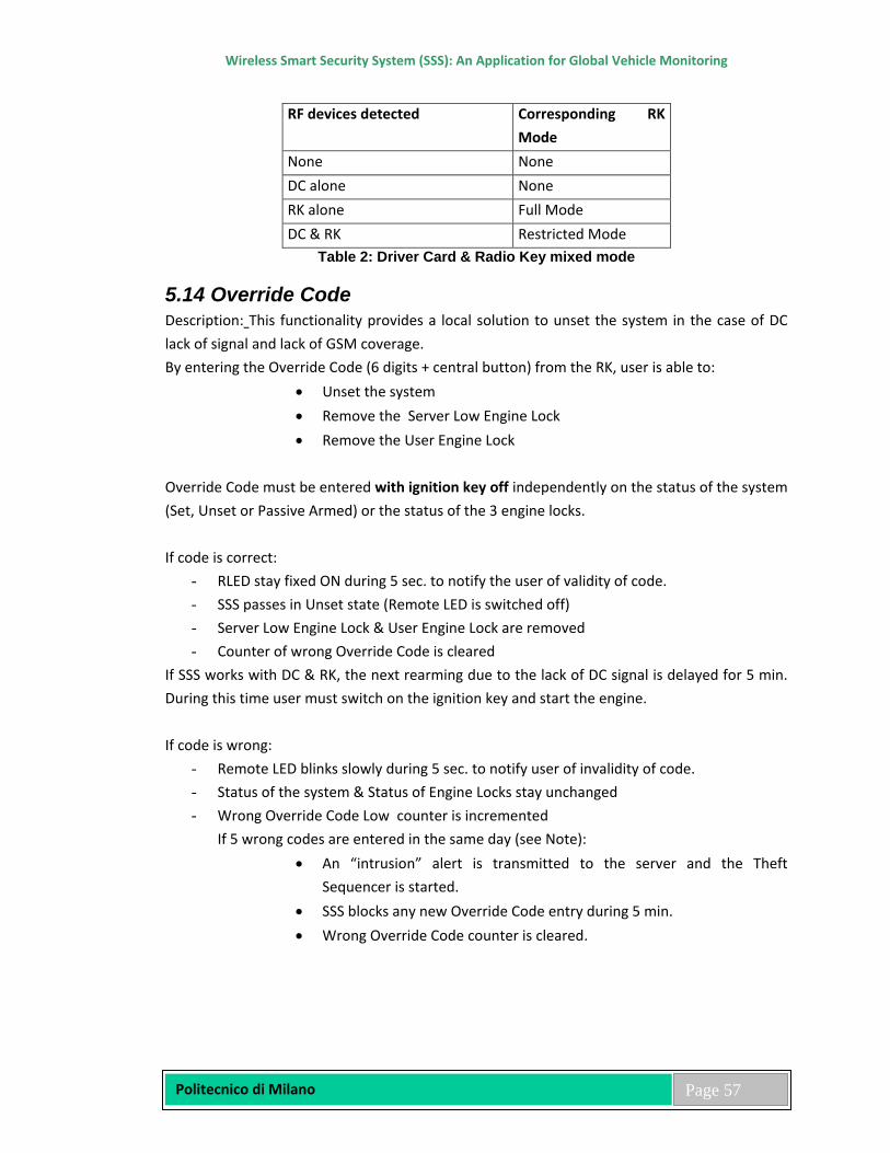
Wireless Smart Security System (SSS): An Application for Global Vehicle Monitoring
Politecnico di Milano
Page 57
RF devices detected Corresponding RK Mode
None None DC alone None RK alone Full Mode DC & RK Restricted Mode
Table 2: Driver Card & Radio Key mixed mode
5.14 Override Code Description: This functionality provides a local solution to unset the system in the case of DC lack of signal and lack of GSM coverage. By entering the Override Code (6 digits + central button) from the RK, user is able to:
• Unset the system • Remove the Server Low Engine Lock • Remove the User Engine Lock
Override Code must be entered with ignition key off independently on the status of the system (Set, Unset or Passive Armed) or the status of the 3 engine locks. If code is correct:
- RLED stay fixed ON during 5 sec. to notify the user of validity of code. - SSS passes in Unset state (Remote LED is switched off) - Server Low Engine Lock & User Engine Lock are removed - Counter of wrong Override Code is cleared
If SSS works with DC & RK, the next rearming due to the lack of DC signal is delayed for 5 min. During this time user must switch on the ignition key and start the engine. If code is wrong:
- Remote LED blinks slowly during 5 sec. to notify user of invalidity of code. - Status of the system & Status of Engine Locks stay unchanged - Wrong Override Code Low counter is incremented
If 5 wrong codes are entered in the same day (see Note): • An “intrusion” alert is transmitted to the server and the Theft
Sequencer is started. • SSS blocks any new Override Code entry during 5 min. • Wrong Override Code counter is cleared.

Wireless Smart Security System (SSS): An Application for Global Vehicle Monitoring
Politecnico di Milano
Page 58
5.15 Hi-Jack Push Button Analog sensor 1 input is used in case of Hi-Jack Push Button installation: a manually operated switch forces the sensor input to GND level. The pull-up resistor is inside the push button (3 wires). In order to allow the installer to verify the Hi-Jack Push Button installation, when SSS is in first installation mode and the analog sensor 1 is properly configured (threshold defined) each time the Hi-Jack Push Button is pressed the status led blinks fast as long as the button is maintained pressed.
5.16 Power Management The Power Consumption Management is one of the main problems for this kind of products. The SSS design require that the main micro-controller have to be put in “Stop Mode” when the ignition key is off and only the secondary microcontroller (ST7) can be in fully functional state. In “Stop Mode” the SSS can be waked up by the following pins: WAKE UP LINE #
WAKE UP LINE SOURCE
0 SW interrupt - no HW connection – NOT USED 1 USB wake-up event: generated while exiting from suspend mode – NOT USED 2 Port 2.8 - External Interrupt – Spare Input 3 3 Port 2.9 - External Interrupt – Shock sensor 4 Port2.10 - External Interrupt – Battery tamper 5 Port 2.11 - External Interrupt – +15 6 Port 1.11 - CAN module receive pin (CANRX). 7 Port 1.13 - HDLC clock (HCLK) or I2C.0 Clock (I0.SCL) – Spare input 1 8 Port 1.14 - HDLC receive pin (HRXD) or I2C.0 Data (SDA) – Spare input 2 9 Port 0.1 - BSPI0 Slave Input data (S0.MOSI) or UART3 Receive Data Input (U3.Rx)
– ST7 10 Port 0.2 - BSPI0 Slave Input serial clock (S0.SCK) or I2C.1 Clock (I1.SCL) – Not
used as wake-up 11 Port 0.6 - BSPI1 Slave Input serial clock (S1.SCK) – Not used 12 Port 0.8 - UART0 Receive Data Input (U0.Rx) – Not used as wake-up 13 Port 0.10 - UART1 Receive Data Input (U1.Rx) - GSM 14 Port 0.13 - UART2 Receive Data Input (U2.Rx) – Not used as wake-up 15 Port 0.15 - WAKEUP pin or RTC ALARM – RTC wake-up
The SSS design reduces the power consumption by means of optimized policies of usage of the peripheral modules, in particular GSM and GPS (these policies will be explained in the following of this chapter).
Wireless Smart Security System (SSS): An Application for Global Vehicle Monitoring
Politecnico di Milano
Page 59
5.17 GSM Management To reduce the power consumption the GSM module automatically goes in sleep mode when it is not in transmission mode. In sleep mode GSM module is able to receive SMS. The GSM management includes the checking of the GSM Network Parameters every 7 seconds: • SIM card (Ready, Waiting for SIM PIN, Not Inserted, Failure) • GSM Network Registration • GSM Network Signal Quality • GSM Network Operators If a GSM problem is detected or one time per day in any case a total new configuration of GSM module is made. Sleep Mode Enter Conditions: GSM MODULE is put in Sleep Mode if all the following conditions are present: - Ignition Key OFF AND - GSM MODULE not already in Sleep Mode AND - SMS FIFO is empty AND - NO "SMS" are pending into the SIM Card AND - GSM MODULE is registered to the network (home or roaming) Sleep Mode Exit Conditions: GSM MODULE wake up alone automatically when an SMS is received from the server. GSM MODULE is waked up if one of the following conditions is present - an AT command must be transmitted to the GSM MODULE OR - every hour (periodic wakeup to read gsm_parameters) OR - if ignition key is turned ON
5.18 GPS Management GPS module is always on when the ignition key is on and it is switched off when the ignition key is off. GPS can be wake-up with ignition key off due to the following events: • Shock detection • Server forced “nav” commands • Theft tracking (periodically on)
Wireless Smart Security System (SSS): An Application for Global Vehicle Monitoring
Politecnico di Milano
Page 60
When SSS is Armed or Passive Armed and detects a shock (GPS Wake Up event), the GPS module is kept powered for 3 min. more after the first valid fix or until a timeout period of 10 min. is elapsed to detect a vehicle movement. If this is the case a “mot” Alert will be sent. If a GPS problem is detected the module is powered off/on and initialized. A “Time reference” field provides the server with the GPS/UTC type data information, for further processing (see “nav” field of “dat” frame).
5.19 SMS Fifo Some rules to transmit and receive SMS have been defined inside the GSM management. When an SMS can not be correctly transmitted, for example when the S is out of GSM Network coverage, the SMS is stacked in the memory; a memory stack of 30 Outgoing SMS is available to avoid loosing messages and to maintain the order of the messages. A category of SMS that cannot be stacked into FIFO is “inf” type messages, because as a reply to a “Query_debug_info” messages, they contain also information regarding the SMS FIFO stack area pointer. The SMS transmission is retried every 10 sec. until GSM network problem doesn’t disappear. SMS fifo can enable/disable using server profile command and it is never used if SSS is in first installation mode. SMS fifo can be cleared by Factory Setting command, Kill command and when SMS fifo is disabled by server profile command. On each SMS stored in the fifo the first character is changed in upper case to allow server to distinguish between real time SMS and stored SMS
5.20 Time Stamping Time stamping is used to stamp with date and time the messages generated by SSS (data and time are related to generation and not to transmission of SMS). Time stamp is composed by UTC data and time and an offset counter in seconds.
5.21 Remote Led Remote LED is mainly used to indicate if the system is set (Blinking slowly during inhibition phase and quickly at the end) or if the system is unset (Off). The Remote LED is also used in specific phase: • Initialization phase • Learning mode • Open/Close set-up phase • Override / Emergency and Access Code good or bad • Radio Key / Driver Card press button acknowledge • Execution of server immobilization and activation command
Wireless Smart Security System (SSS): An Application for Global Vehicle Monitoring
Politecnico di Milano
Page 61
Remote LED is also used when SSS is in First Installation Mode, to check devices / switches attached to the analog sensor 1 input.
5.22 Boot Loader With a Boot Loader SSS firmware can be upgraded using a PC with a specific loader program. Boot Loader uses UART 2 to communicate with the PC, and this port is available on the harness: it is possible to program the SSS without open the plastic box. Please refer to the “SSS Boot loader Specification” and “SSS Programmer” documents for additional information.
5.23 Garage Function The Garage function is necessary when a vehicle must be taken to a garage for maintenance. The activation/deactivation of garage mode on SSS is only authorized using the server (vocal or Web application). The time in which the vehicle is in garage mode has to be stored by the server for insurance companies after theft consultation. SSS has to acknowledge to the server the reception of garage activation/deactivation commands. The Garage function has no impact on the SSS if it receives a Garage Mode On message when system is set (the protection is still fully working until SSS moves to Garage mode as an Unset action is performed). When system is unset, passive arming, theft sequencer and the entire alert are blocked except zone-in, zone-out, speed and sab.
5.24 Transport Function The Transport function is necessary when a vehicle is transported by boat or train. The activation/deactivation of transport mode on SSS is only authorized using the server (vocal or Web application). The Transport function for the SSS consists to disable only the shock detection and GPS wake-up due to shock sensor, with system Set/Unset/Passive Armed. If system is set and ignition key is turned on, SSS would be able to send an “ign” and “mot” Alerts, because GPS is powered when ignition key is on. Please note that Garage & Transport Mode are exclusives.
5.25 Passive Arming/Rearming Function This function has to be enabled by default and set on or off in line with requirements due to a particular fitting configuration. The disable command has to be implemented but it does not have to be usable in Web application to the end-user. In the case of a Driver Card learnt, the Passive Arming must be disabled by the server, because the “move to Set” operation is already a “passive” one. Arming condition:
Wireless Smart Security System (SSS): An Application for Global Vehicle Monitoring
Politecnico di Milano
Page 62
• +15 Key Off for more than 5 min. (fixed time) The system will automatically Set:
o 5 min. after the ignition key is switched Off o 5 min. after the system has been disarmed and the ignition is not switched On
(this is called Rearming) • +15 Key Off and door opening with a timer of 1 min. (fixed time). The system wills
automatically Set 1 min. after the ignition is switched Off and door opening. In passive arming condition the SSS does not operates CDL, does not send shock alert and blinks the remote LED as in normal arming state. If the ignition key is switched On with the system in passive arming the user has to press the Radio Key central button once (unset) within 30 s. to Unset the system, if not the system starts the Theft Dissuasion and Theft Tracking.
5.26 Free SIM Card Function
This function has been added to simplify the use of SIM Card of different operators. SSS always use the SMSC number stored in the SIM Card to send an SMS to the Server. If the Server changes this number by using a Parameter Setup command, SSS changes this number directly in the SIM Card. If the Server asks SSS for this number by using a Query Parameters command, then SSS reads it from the SIM Card and resend it to the Server in response. The Factory Setting command cannot change this number.
5.27 SMS Protocol Security The function covers the effort of making secure the SMS communication protocol between server and client. A MAC (Message Authentication Code) field is included in each SMS (incoming and outgoing). It's a computed code of 4 bytes (8 hexadecimal digits). When an SMS is generated (by server or SSS) this code is computed using the authentication key, the MID and the content of the SMS to be transmitted in accordance to SSS Protocol; afterwards is added to the SMS and sent. When the SMS is received (by server or SSS), the receiver checks the validity of this code, if the MAC is invalid the SMS is rejected. In case of an invalid command request in the current SSS mode, a “mod” response message is sent to inform the server (e.g. a Factory Setting command when ignition is ON). Each SSS use a different random Key (generated and loaded in the factory). A MID (Message IDentifier) field is included in each incoming SMS (2 bytes, 4 hexadecimal digits). It's simply a 2 bytes counter incremented by the server each time this one sends a command to the SSS (one counter per SSS). Server adds this information to the SMS, and SSS must resends this information only for the SMS execution acknowledgement. Goal of this code is to make a cross reference between the commands sent by the server and SMS execution
Wireless Smart Security System (SSS): An Application for Global Vehicle Monitoring
Politecnico di Milano
Page 63
acknowledgements sent by SSS. This code is also used by SSS to reject commands already received (Message-Window functionality). For further details about Message-Window, see “Commands, Answers, Acknowledgements, Errors” par.
5.28 Theft Tracking Mask Theft Tracking mask is used to authorize or not each theft event to start a theft tracking. The events we can mask using a server user profile command are:
• Main battery Tamper (SAB) • Intrusion (INT) • Ignition Key (IGN) • Theft Lock Server command • Movement detection (MOT)
5.29 UPEA Mode Goal of this feature is to implement a driver identification procedure (mandatory for integrated systems). When SSS is configured in UPEA mode the engine lock is only activated by the server. If UPEA Step 1 is selected (UPEA Mode Parameter = 1), only engine lock activation by the server is available (no driver identification). The Radio Key cannot act on engine lock. UPEA Step 2: the following procedure is enabled when UPEA mode parameter is equal to 3 (1+2) and disabled when this parameter is cleared (see SSS Communication Protocol 1.00 / USER PROFILE command). An external buzzer is connected to the LOW SIDE OUTPUT pin of SSS to inform the driver that a code is required.
5.30 Identification Procedure 1 Each time SSS is armed or passive armed an Access Code is required; the driver has to perform the following action:
1. Must use the RK (central button) to open the vehicle and unset the system. When the system is unset, the Status LED stops to blink.
2. Must enter a valid ACCESS CODE using the Radio Key to be identified (4 digits and central button to validate) before turning ON the engine. If Access code is valid, buzzer beep two times (200ms ON, 200ms OFF, 200ms ON and then OFF) (No further code will be asked to the driver while the system stays unset).
Wireless Smart Security System (SSS): An Application for Global Vehicle Monitoring
Politecnico di Milano
Page 64
If Access code is invalid , buzzer beeps one long continuous time (5s) but user can start the engine in any case (access code valid or invalid).
If the driver switches ON ignition key without entering the right ACCESS CODE when the system is unset or passive armed then the following actions will be performed by SSS:
- The engine can be started but, a timer is started and, when this timer reaches 60 seconds, if no valid access code has been entered, the buzzer beeps during 4s (frequency 2Hz).
- When this timer reaches 120 seconds, if no valid access code has been entered the buzzer beeps during 4s (frequency 2Hz).
- When this timer reaches 170 seconds (180s for FW<2.24), if no valid access code has been entered then:
- the buzzer beeps during 4s (frequency 2Hz) - an IGN Alert is sent to the server - Theft sequencer is started - If the vehicle is moving a “mot” Alert is probable to be sent
Access code time validity: when a correct access code has been entered, no further access code will be asked while the system stays unset. If UPEA step 2 is enabled and if the system is unset, then if the driver forget to enter the Access Code and switch on ignition key and switch off ignition key within 170 seconds, nothing occurs (no alert, no theft sequencer, just buzzer notifications), but SSS memorizes value of this timer . This timer is incremented each time ignition key is ON without driver recognition and UPEA step 2 enabled. If UPEA step2 is enabled and if the driver switches ON ignition key when the system is set (not passive armed), alert IGN is sent immediately and theft sequencer is also started immediately. When the user enters 5 consecutives WRONG Access Code an alert COD is sent to the server. To avoid the possibility of false “mot” or “mOt” Alerts within identification time, those are disabled for the whole 170s time period. Information given by the buzzer: 2 shorts beeps (200ms ON, 200ms OFF, 200ms ON, OFF)
Access code given accepted and correct
1 long continuous beep (5s ON, OFF) Access code given by user, accepted but INCORRECT
4s of modulated beep (frequency = 2Hz)
Wireless Smart Security System (SSS): An Application for Global Vehicle Monitoring
Politecnico di Milano
Page 65
An access code is required
5.31 Identification Procedure 2 The system goes automatically in passive arming 30 seconds after the ignition key is switched off. Each time the system is passive armed an identification procedure is required to the driver that has to press a hidden button to disarm the system. An external buzzer is connected to the SSS system to inform the driver that an identification procedure is needed. If the driver switches on ignition key or move the car without execute the identification procedure the following actions is performed by the system:
- A timer is started and when this timer reaches 60 seconds, if no valid identification procedure has been entered, the buzzer beeps during 4s (frequency 2Hz).
- When this timer reaches 120 seconds, if no valid identification procedure has been entered the buzzer beeps during 4s (frequency 2Hz).
- When this timer reaches 170 seconds, if no valid identification procedure has been entered then:
- the buzzer beeps during 4s (frequency 2Hz) - an IGN Alert is sent to the server - Theft sequencer is started - If the vehicle is moving a “mot” Alert is probable to be sent
5.32 Backup Battery Management When SSS is powered-on in first installation mode the backup battery is continuously charged for 24 hours independently of Ignition Key status. This initial backup battery charging procedure is enabled by default and it is interrupted after 12 hours at the first switching off of the Ignition Key or after 24 hours. When SSS is powered-on in normal mode the initial backup battery charging procedure is not activated. During the normal functionality the backup battery is charged only when the ignition key is on, and the temperature is comprised from 0°C to 60°C; it is not charged when the ignition key is switched off. If the temperature exits from the limits when the ignition key is on the charge is suspended, when the temperature reenters in the limits the charge is reactivated. The correct operation of the re-charge circuit and charge-test circuit is detected by a voltage level variation during changing status (disable-->enable and enable-->disable). In case of failure an acc alert is sent to the server. The error on the re-charge circuit is signalled if the difference between the voltage with the battery in charge and the voltage with the battery not in charge is less then a fixed value for 4 consecutive measurements. The error on the charge-test circuit is signalled if the difference between the voltage with the battery not in
Wireless Smart Security System (SSS): An Application for Global Vehicle Monitoring
Politecnico di Milano
Page 66
discharge and the voltage with the battery in discharge is less then a fixed value for 4 consecutive measurements.
5.33 Functionalities Improvements Client/Server Communication Protocol changed
• A dedicated ACTIVATION command has been created to switch SSS in Normal Mode. ONLY this ACTIVATION command is able to switch SSS in Normal Mode. Commands THEFT_UNLOCK, SECURE_UNLOCK stop to switch SSS in Normal Mode.
• “Stealth theft” mode added in ENGINE LOCK / IMMOBILIZATION Command.
This particular mode is intended to start/restart a theft sequence without acting on the engine locks.
5.34 Support of SIM card without pin code enhanced Firmware is able now to detect automatically if the SIM card requires or not a PIN Code. No server configuration is required to support these SIM cards. In the previous implementation of this feature in it was mandatory to set from the server the parameter PAR_PIN_CODE to “----“.
5.35 Give Possibility to the fitter to test the Perimetry It’ now possible for the fitter to test the “Perimeter” when SSS is in First Installation. In this new firmware if the “Perimetry” feature is enabled and if System is SET and if SSS is in First then each time the driver door is opened:
- A temporisation of Par_door_open_time * 100ms is performed - If after the elapsing of this time System remains SET then
+ The Horn is activated 1s + The blinkers are activated 20s + The Remote Led flashes one time
5.36 Enable the Shock Alert and the Shock Dissuasion also when system is Passive Armed This feature is enabled when the parameter PAR_ENABLE_SHOCK_IN_PA=”y” and disabled when this parameter is equal to “n”. By default this parameter is equal to “n”. This parameter has to be changed from the server
Wireless Smart Security System (SSS): An Application for Global Vehicle Monitoring
Politecnico di Milano
Page 67
5.37 Bus Interface SSS, as a Bus Master device, is able to manage the following Bus additional external modules, enabled/disabled by specific server commands: Siren: SSS can use this siren module in alternative of horn. Engine Immobilizer: SSS can use this module as a secondary engine lock controlled by the server. The second engine lock is activated on the execution of the Theft Lock Command and it is deactivated on the execution of the Theft Unlock Command. Ultra Sound Sensor: this sensor can be an alert source for the SSS module. Level Monitor Sensor: this sensor can be an alert source for the SSS module. SSS, as a Bus Slave device, can be interfaced to a Bus Master Control Unit SSS can be armed/disarmed by a Bus Master CU (SSS Slave from the arm/disarm point of view), SSS dispatches alerts generated by the Bus Master CU. SSS can arm/disarm a Bus Master CU (SSS Master from the arm/disarm point of view), SSS dispatches alerts generated by the Bus Master CU. SSS can just dispatch alerts generated by a Bus Master CU, but each device (SSS and Master CU) has its own arm/disarm logic.
5.38 CAN Bus Functionalities SSS can be connected to High and Low speed CAN Bus. Normally (Standard Security) the Driver Card is not used and the 5-buttons Radio Key is used as override when SSS is connected to the CAN Bus. SSS detects from CAN Bus the following messages:
• set/unset by original radio key – used to set/unset the SSS • perimetry – used to detect intrusion • +15 – used to detect ignition key • TP-OK – used to exit from passive arming
Standard Security: SSS is armed/disarmed via CAN Bus using original radio key. SSS can only be set/unset by the original radio-key when in Can Bus Mode. Driver Card is not supported. The following information is taken from the CAN Bus:
Wireless Smart Security System (SSS): An Application for Global Vehicle Monitoring
Politecnico di Milano
Page 68
□ OE Radio Key Lock Button – SSS goes in full set state if or when all doors are closed. □ OE Radio Key Unlock Button – SSS goes in unset state.
□ Close Action of the Key in the Key-Cylinder – SSS goes in set state (platform
dependent).
□ Open Action of the Key in the Key-Cylinder – SSS stays in set state and sends an intrusion alert if or when door is opened.
□ Transponder OK – SSS goes in unset state from passive arming or from set state
(platform dependent).
□ Driver Door Status – If in set state, SSS goes in alarm state and sends an intrusion alert when door is opened. This message is also used for passive arming activation. No alert is sent if system is in passive (if this special feature is not enabled).
□ Passenger Doors Status - If in set state SSS goes in alarm state and sends an intrusion
alert when door is opened. No alert is sent if system is in passive (if this special feature is not enabled).
□ Ignition key Status – This message is used to GPS wake-up with system unset and
Ignition alert with system set.
□ Trunk Status – If in set state SSS goes in alarm state and sends an intrusion alert when trunk is opened. No alert is sent if system is in passive (if this special feature is not enabled).
□ Bonnet Status - If in set state SSS goes in alarm state and sends an intrusion alert when
bonnet is opened. No alert is sent if system is in passive (if this special feature is not enabled).
□ Trunk Release Button – This message is used to acknowledge an authorized opening of
the trunk without generating an alert when SSS is in set state (platform dependent).
5.39 CAN Bus Functionalities with Client/Server Protocol With the Client/Server Protocol two kind of Can Bus Operating Mode have been introduced:
Wireless Smart Security System (SSS): An Application for Global Vehicle Monitoring
Politecnico di Milano
Page 69
• Standard Security: o SSS is armed/disarmed via CAN Bus using Original Radio Key.
• High Security: o SSS is armed by the Original Radio Key or for passive arming. o SSS is disarmed by the Original Radio Key and only if/when Driver Card
presence is detected (SSS is not disarmed if Original Radio Key Unlock Button is pushed but Driver Card presence is not detected).
5.40 Radio Frequency 2.4 GHz Interface This module manages all the services for handling of Radio Frequency 2.4 GHz Controller. The goal is to have a 2.4 GHZ Radio Frequency networking where different modules are managed or can be easily added. The RF 2.4 GHz technology is managed and an RF network protocol is implemented. Bidirectional short range RF capability able to communicate with wire-less add-on modules (Driver Card, Relay, Siren, Self Powered Push Buttons Panel, Display, Sensors, …) is defined and implemented. The 2.4 GHz technology with embedded antenna and Texas Instrument Chipcon CC2500 Transceiver have been chosen. The basic requirement is to handle:
• 2.4 GHz Driver Card The Driver Card simple transmits a frame at periodical time:
o each 3 sec. with a battery duration of > than 2 years o each 5 sec. with a battery duration of > than 3 years
• 2.4 GHz Wireless Siren The siren goes automatically in alarm if tampered (power disconnection), it is armed/disarmed and activated/deactivated by specific SSS commands. The siren is always in “listen mode” and acknowledges all the commands received by the SSS or automatically/periodically sends alarm frame when tampered.
• 2.4 GHz Wireless Relay The relay is always in “listen mode” and acknowledges all the commands received by the SSS or automatically/periodically sends alarm frame when tampered (power disconnection). Wireless relay is designed able to be used as engine lock (high current automotive relay). The wireless relay has also the +15 input, for safety reason the engine lock is activated only when the vehicle is switched off for more than one minute.
Wireless Smart Security System (SSS): An Application for Global Vehicle Monitoring
Politecnico di Milano
Page 70
5.41 RF 2.4 GHz Network Protocol General Criteria The basic choice is to use SimpliciTI (Simple Modular RF Network) of Texas Instruments like simplified RF network protocol solution: a wireless solution of low power, low cost and low data rate networks without to know the details of the wireless network support. The SimpliciTI-based network should be easy to develop and easy to deploy. The simplified development environment should have a simple API that enforces details of the RF communication without complex configuration by developers. The simplified RF environment should also make it easy for customers to develop applications that make the solution easily implemented in the field by end users. Radio and network configuration shall be encapsulated and hidden from the application layer. The API set for messaging in this environment shall be of the open/read/write/close variety. There shall be access run-time configurability using an ioctl()-like method. The chosen Network Topology is Peer-to-Peer: Rx devices that are on will receive frames directly from the source device. These are considered peer-to-peer relationships. The network topology is entirely peer-to-peer. Even if all messages are broadcast, from the application perspective messages are coming from a peer. In the defined solution all the 2.4 GHz modules are considered End Devices. The End Device realizes the application layer functionality. An End Device may or may not be always on. End Devices may be Rx/Tx devices or they may be Tx-only devices. Medium Access by a device to transmit is not managed by listen-before-talk procedure (CCA before transmitting). The Clear Channel Assessment (CCA) is not used to indicate if the current channel is free or busy. This feature requires sending radio interface in Rx mode (about 1 mSec. for RRSI to be valid) before transmitting, increasing power consumption and breaking Tx/Rx device synchronization. The Encryption choices for encrypt and decrypt messages are currently hardware or software. The CC2500 radio does not have native support for hardware encryption so on platforms using this radio the encryption is in software. When encryption is enabled all fields except the address and encryption context fields are encrypted. Frequency Agility is intended to support robustness by providing a means to change frequency when a specific frequency is noisy or otherwise ineffective compromised. It is realized in the form of channel migration. The network shall support migrating to alternate frequencies if an existing frequency offers too much radio interference. It will be driven by a frequency table that is populated at build time. Devices that can receive packets can detect that they are on the incorrect frequency by not receiving an acknowledgment after sending and resending a frame. The sender then steps
Wireless Smart Security System (SSS): An Application for Global Vehicle Monitoring
Politecnico di Milano
Page 71
through the frequency table until the acknowledgment is received. This is the scenario encountered by new devices trying to join a network and sleeping devices that awaken after a migration has occurred. Changing frequency may also be actively imposed. Frame Acknowledgement is the responsibility of the application. The acknowledgment is part of the application peer-to-peer discipline. The network supports up to 250 kbps at 2.4 GHz. SimpliciTI is intended to support customer development of wireless end user devices in environment in which the network support is simple and the customer desires a simple means to do messaging over air. The protocol is oriented around application peer-to-peer messaging. 6.42 SimpliciTI Software conceptually supports 3 layers. The Application Layer is the only portion that the customer needs to develop. The communication support is provided by a simple set of API symbols used to initialize and configure the network, and read and write messages over air. The architecture does not strictly follow the OSI Reference model. Application Layer: using the SimpliciTI API the application can send/receive messages to/from an application peer on another device. Management of the network itself is supported by SimpliciTI network “applications”. The Network Layer actually spans the boundaries of the standard OSI model, as it collapses and hides functionality from the application. Run time adjustment of some network parameters may be accessible from application via an ioctl-like interface. Network parameters can include:
• base frequency and frequency spacing • number of frequencies supported (for frequency agility table) • modulation method and data rate and other general radio parameters • default and generated network encryption keys • number of store-and-forward messages to hold • device address • repeat rates on Tx-only devices • join and link tokens
The Minimal RF Interface (MRFI) layer abstracts what is basically a frame read/write interface to the radio. Different radios supported by SimpliciTI require different implementations but the basic interface offered to the network layer is the same for all radios. Different radios offer different levels of support for typical Data Link and PHY layer responsibilities. MRFI encapsulates these differences. The general Frame Layout (Packet Format) is shown below. The Frame Length could be 22 bytes + Application Payload (maximum 16 bytes). This frame length corresponds to a FIFO size for packet of 14 bytes + 16 bytes payload = 30 bytes. Two status bytes could be appended to
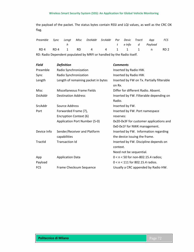
Wireless Smart Security System (SSS): An Application for Global Vehicle Monitoring
Politecnico di Milano
Page 72
the payload of the packet. The status bytes contain RSSI and LQI values, as well as the CRC OK flag. Preamble Sync Lengt
h Misc DstAddr SrcAddr Por
t Device Info
TractId
App Payload
FCS
RD 4 RD 4 1 RD 4 4 1 1 1 n RD 2 RD: Radio Dependent populated by MRFI or handled by the Radio itself. Field Definition Comments Preamble Radio Synchronization Inserted by Radio HW. Sync Radio Synchronization Inserted by Radio HW. Length Length of remaining packet in bytes Inserted by FW on Tx. Partially filterable
on Rx. Misc Miscellaneous Frame Fields Differ for different Radio. Absent. DstAddr Destination Address Inserted by FW. Filterable depending on
Radio. SrcAddr Source Address Inserted by FW. Port Forwarded Frame (7),
Encryption Context (6) Application Port Number (5-0)
Inserted by FW. Port namespace reserves: 0x20-0x3F for customer applications and 0x0-0x1F for NWK management.
Device Info Sender/Receiver and Platform capabilities
Inserted by FW. Information regarding the device issuing the frame.
TractId Transaction Id Inserted by FW. Discipline depends on context. Need not be sequential.
App Payload
Application Data 0 < n < 50 for non-802.15.4 radios; 0 < n < 111 for 802.15.4 radios.
FCS Frame Checksum Sequence Usually a CRC appended by Radio HW.

Wireless Smart Security System (SSS): An Application for Global Vehicle Monitoring
Politecnico di Milano
Page 73
Chapter 6
Conclusion and Future Considerations
In today’s automated world, lack of security means that the network provides an organized crime and other nation-states to steal money—and more. This is an increasingly serious social security problem. To Create and deliver world class security and surveillance solutions, Microcontroller based Smart Security System (SSS) devices are more in use. Microcontroller can perform several functions at a time and also can make a circuit small and efficient. Using a centralized Microcontroller, we can compactly and smartly design a circuit and reprogram it whenever we want to modify or upgrade the system. In this project, controlling is done by Microcontroller and message sending and monitoring system are done by GSM and GPS Module. Though it is smart security system but still it has some problems like it is important to periodically update the system with the customer information and secondly discover more ways we can solve our toughest tooling and automation challenges.
In future, if resource and necessary support are available, monitoring security system with unique live image streaming is possible. Real-time images from cameras mounted in and around the vehicle, streamed to an Independent Monitoring Centre, coupled with inbuilt two way voice communication with the driver, can enable bus operators to deal with a situation as it happens. Immediate, accurate on site intelligence can enable better response decisions to be made. Forward facing cameras can also be installed to monitor driving standards and to provide footage, which can be used as evidence in court in the event of an accident.
Wireless Smart Security System (SSS): An Application for Global Vehicle Monitoring
Politecnico di Milano
Page 74
References: [1] Microcontroller Data Manuals, ST Microelectronics Semiconductor Products Inc., Geneva,
CH1228, Switzerland. [2] U-BLOX AG Data Manual, U-BLOX Products Inc., Thalwil, 8800, Switzerland. [3] GSM engine Data Manual, Siemens Products Inc., Munich, Germany. [4] Temperature Sensors Data Manual, Analog Device Semiconductors Inc.,
Massachusetts, United States. [5] Components Datasheet (http://datasheetcatalog.com,
http://www.datasheetarchive.com, http://datasheet4u.com, http://datasheet.in) [6] Enhanced Products from Texas Instruments, Texas, United States. [7] Global Vehicle Security System Designing Company, Cobra Automotive Technologies SpA,
Varese, Italy. [8] Autowatch Car Alarms, South Africa. [9] The vehicle association of South Africa, Gauteng, 1685, South Africa [10] Enforcer Security, Taipei, 106, Taiwan. [11] Magtec Products (USA), 7000 Adams Street, Suit B110, Willowbrook, IL 60527. [12] Department of Electronic and Informatics, Politecnico di Milano, Italy. [13] Overton Security Services, Inc. 39300 Civic Center Drive, Suite 370 Fremont, CA 94538 [14] D. Gottuk, Ph.D., Full-Scale House Fire Experiment for InterFIRE VR, Report of Test,
November 2, 1999, Revised April 10, 2000, Available: http://www. interfire.org/features/fire _ experiment.asp.
[15] MSP430 IAR C/C++ Compiler Reference Guide, Texas Instrument, Dallas, TX 75266-019. [16] Proteus 7.2 Microcontroller Simulation Software, Labcenter Electronics Ltd., BD235AA,
England. [17] Code Vision AVR Microcontroller Programming Software, HP InfoTech S.R.L., Bucharest,
ROMANIA. [18] A. Shrinath, A. Emadi, “Electronic Control Units for automotive electrical power systems:
communication and networks”, Journal of Automobile Engineering, Proc. of the Institution of Mechanical Engineers, vol. 218, partD, 2004, UK, pp. 217 – 230.
[19] N. Kurata, B. F. Spencer, Jr, and M. Ruiz-Sandoval, “Application of Wireless Sensor Mote for Building Risk Monitoring”, IEEE, SECON, Available on: http://www.unl.im.dendai.ac.
[20] R. C. Luo, K. L. Su, and K. H. Tsai, “Intelligent security robot fire detection system using adaptive sensory fusion method,” in Proc. IEEE Int. Conf. Ind. Electron. Soc., 2002, vol. 4, pp. 2663–2668.
[21] R. C. Luo, S. Y. Lin, and K. L. Su, “A multiagent multisensor based security system for intelligent building,” in Proc. IEEE/SICE/RSJ Int. Conf. Multisensor Fusion Integr. Intell. Syst., 2003, pp. 311–316.
[22] The Advanced Multi-Criteria Fire Detector, System Sensors, 3825 Ohio Avenue, St. Charles, IL 60174.
[23] Safety and Health Administration, U.S. Department of Labor, 200 Constitution Ave., N.W. [24] A. Neubauer, “Genetic algorithms in automatic fire detection technology,” in Proc. 2nd
Int. Conf. Genetic Algorithms Eng. Syst.: Innovations Appl., 1997, pp. 180–185. [25] Wobschall, D., Prasad, H.S., "Esbus- a sensor bus based on the SPI serial interface",
Proceedings of IEEE Sensors, Orlando, USA, June 2002,pp.1516- 1519.
Wireless Smart Security System (SSS): An Application for Global Vehicle Monitoring
Politecnico di Milano
Page 75
[26] B. Rajesh Kumar, Member, IEEE, K. Sridharan, Senior Member, IEEE, and K. Srinivasan,”The Design and Development of a Web-Based Data Acquisition System”, IEEE TRANSACTIONS ON INSTRUMENTATION AND MEASUREMENT, VOL. 51, NO. 3, JUNE 2002.
[27] O. Postolache, P. Silva Girb, H. Geirinhas Ramos, M. Dias Pereira,' "A Distributed Virtual Instrument for Indoor Air Monitoring", Proc. ICEMI'2001, Guilin, China, November 2001.
[28] A. Wielgat, “What’s the frequency? suppliers seek new applications for RF technology,” in Automotive Industries. Tuscaloosa, AL: Randall, 2001.
[29] K. Marneweck, An Introduction to Keeloq Code Hopping. Chandler, AZ: TB003 Applicat. Notes, Microchip Technol., Inc., 1996.
[30] “Microchip Inc., Data sheet for HCS300,” in KeeLoq Code Hopping Encoder. Chandler, AZ: Microchip Technol., Inc., 2000.
[31] J. Gordon, U. Kaiser, and T. Sabetti, “A low cost transponder for high security vehicle immobilizers,” in Proc. ISATA’96, Florence, Italy, 1996, 96AE001.
[32] J. Gordon, Designing Codes for Vehicle Remote Security Systems. Herfordshire: Concept Laboratories Ltd. and Police Science Develop. Branch, 1994, ch. U.K., pp. 1–22.
[33] “Microchip Inc., data sheet for HCS412,” in KeeLoq Code Hopping Encoder and Transpnder. Chandler, AZ: Microchip Technol., Inc., 2000.
[34] D. Juzswik, “Evolving automotive access systems,” in Proc. 4th Int. Conf. Vehicle Electronic System,Coventry, U.K., Jun. 2001, pp. 8.2.1–8.2.7.
[35] S. Schmitz, J. Kruppa, P. Crowhurst, T. Oexle, and W. Ulke, “New door closure concept,” SAE Automot. Eng. Int., vol. 108, no. 9, pp. 118–120, Sep. 2000.
[36] B. Schneier, Applied Cryptography. New York: Wiley, 1994. [37] H. Krawczyk, “How to predict congruential generators,” in Advances in Cryptology-
CRYPTO 89. New York: Springer-Verlag, 1990, vol. 435, Lecture Notes Comp. Sci., pp. 138–153.
[38] A. I. Alrabady and S. M. Mahmud, “Some attacks against vehicles’ passive entry security systems and their solutions,” IEEE Trans. Veh. Technol., vol. 52, no. 2, pp. 431–439, Mar. 2003.