Wireless Power Transfer: From Far Field to Near...
63
Wireless Power Transfer: From Far Field to Near Field Prof. Jenshan Lin University of Florida 1
Transcript of Wireless Power Transfer: From Far Field to Near...

Wireless Power Transfer:
From Far Field to Near Field
Prof. Jenshan Lin
University of Florida
1

• Far-field WPT – an overview of historical developments
• Challenges of far-field WPT
• From far-field WPT to near-field WPT
• Near-field WPT
– Overview
– Difference between far-field WPT and near-field WPT
• Magnetic coupling near-field WPT
– System architecture
– Design considerations
– Examples
• Commercialization and standards
• Conclusion
Outline
2

Nicola Tesla proposed it in 19th Century to transmit electric
power without using wires.
Hot topic in 1960’s-70’s – NASA/DOE’s interest to collect
solar energy in space and beam it to earth.
Several potential applications (some might sound crazy):
Remote transmission of energy for space applications
Remote charging of bio-implanted devices
Remote powering of unmanned aircrafts, vehicles, robots
Remote powering of wireless sensors, especially for sensors
located in hard-to-reach environment
An extension of existing power grid system
Controlling the destructive storms, e.g. the path of hurricane
3
Far-Field Wireless Power Transmission

WPT History - more than one century
4
1899 – Tesla’s first experiment to transmit power without wires. 150 kHz.
WWII – high power microwave tubes developed.
1958 – 1st period of microwave WPT development. Raytheon, Air Force, NASA.
1963 – Brown in Raytheon demonstrated the first microwave WPT system.
1975 – 54% dc-to-dc efficiency was achieved, receiving 496 W @ 170 cm.
1975 – 30 kW dc received @ 1 mile
1977 – 2nd period of microwave WPT development. NASA/DOE sponsorship. More companies involved. Solar Power Satellite (SPS)
1995 – NASA Space Solar Power (SSP) Program
1975 demonstration
30 kW dc output @ 1 mile
First microwave WPT
100 W dc output, 13%
dc-to-dc efficiency
* W. C. Brown, “The History of Power Transmission by Radio Waves,”
IEEE Trans. Microwave Theory and Techniques, vol. 32, no. 9, pp. 1230-1242, Sept. 1984.

Remote Powering of Helicopter (UAV)
5
Microwave-powered helicopter flying
60ft above transmitting antenna. 10 hr
sustained flight was achieved in 1964.
First “rectenna” – rectifying antenna
integrating solid-state diodes, 1963.
(replacing vacuum tube diodes)
Actual rectenna used on
the helicopter

RF Energy Harvesting From ambient RF emissions (broadband) or from a remote
RF source (narrow band)
Suitable for low power applications, e.g., sensor network
Recently became a very active research area
Several new techniques have been proposed (Class-F,
harmonics termination, wideband, multi-sine, etc.)
* J. A. Hagerty, F. B. Helmbrecht, W. H. McCalpin, R. Zane, and Z. B. Popovic´, “Recycling Ambient Microwave Energy With
Broad-Band Rectenna Arrays,” IEEE Trans. Microwave Theory and Tech., vol. 52, no. 3, pp. 1014-1024, March 2004.
* C. Walsh, S. Rondineau, M. Jankovic, G. Zhao, Z. Popovic, “A Conformal 10 GHz Rectenna for Wireless Powering of
Piezoelectric Sensor Electronics,” IEEE MTT-S International Microwave Symp., pp. 143-146, June 2005. 6

Long Distance Wireless Power Grid
Microwave travels through earth atmosphere twice – overall path ~ 200km
If using high voltage power line, the path would be several thousands km – more environmental effect
λ=5000km @ 60Hz – power line becomes good antenna at long distance.
100 km
* A. P. Smakhtin, V. V. Rybakov, “Comparative analysis
of wireless systems as alternative to high-voltage power
lines for global terrestrial power transmission,”
Proceedings of the 31st Intersociety Energy Conversion
Engineering Conference (IECEC 96), vol. 1, pp. 485-
488, 11-16 August 1996.
7

Attenuation Through Atmosphere
h=
Source: NASA
0.1dB
• One-way attenuation
< 0.1dB for f < 16GHz
One-way attenuation
h
~ 16 GHz
8

Manipulating tropical storms
E. Yu. Krasilnikov, “Prevention of destructive tropical and extratropical storms,
hurricanes, tornadoes, dangerous thunderstorms, and catastrophic floods,”
Nonlinear Processes in Geophysics (2002) 9: 51–59
9

WPT System
dc or ac power is first converted to RF power.
RF power is transmitted by TX antenna to the receiver.
RF power is received by the RX antenna and rectified to dc power which can further be converted to ac power.
Total system efficiency = (ηT)x (ηC)x (ηR)
ηT ηC ηR Efficiency
10

Challenges of WPT
Technical Issues
Beam-forming antennas for directed microwave beam
High efficiency microwave power source (transmitter)
High efficiency microwave rectifier (receiver)
All have to be lightweight to reduce deployment cost
Environmental Issues
Safety concern
Ecological effect
Economic Issues
Cost of the system
Cost of the development
Cost of the deployment
11

Transmission Efficiency as a function of for
optimum power density distribution across the TX
antenna aperture as shown on the right.
Beam-Forming Antennas
Need large antenna aperture or higher frequency to achieve high efficiency.
12
* W. C. Brown, E. E. Eves, “Beamed Microwave Power Transmission and its Application to Space,” IEEE Trans. Microwave
Theory and Techniques, vol. 40, no. 6, pp. 1239-1250, June 1992, quoting G. Goubau and F. Schwering, “On the guided
propagation of electromagnetic wave beams,” IRE Trans. Antennas Propagat., vol. 9, pp. 248-256, May 1961.
Relative cross-sectional power density
distribution across the TX and RX apertures
for various values of

High Efficiency Microwave Power Source
Find devices to generate high power RF.
High efficiency
Low cost
Lightweight
Efficiency is particularly important at high power level. 90%
efficiency of 9 W output means 1 W is lost to heat, whereas
90% efficiency of 90 W output means 10 W is lost to heat.
If efficiency is not high, heatsink will be needed and that
will also increase the cost and weight.
Cost of microwave power amplifier goes up with power
level. Where do you find the cheapest high power source
at 2.4 GHz that can generate 100 W – 1000 W?
13

High Efficiency High Power Microwave Source
14
Microwave tubes have been used to achieve high efficiency and very high output power magnetron, klystron, traveling wave tube (TWT), etc.
Magnetron has the highest efficiency and been used in microwave oven. (>80% at several kW demonstrated). Low cost too.
However, they are bulky and heavy. For very high power, cooling is still an issue.
Toshiba Klystron
5.7GHz, 50MW, 47%, 0.0125% duty cycle
Magnetron inside microwave oven
2.4GHz, ~1kW, ~65% efficiency

Microwave Power Source
* V. L. GRANATSTEIN, R. K. PARKER, C. M. ARMSTRONG, “Vacuum Electronics at the Dawn
of the Twenty-First Century,” Proceedings of the IEEE, vol. 87, no. 5, pp. 702-716, May 1999.
Solid-state devices still have not displaced microwave tubes yet.
GaN
15

Solid-State Microwave Power Source
16
343 W @ 4.8 GHz (C-Band) 101 W @ 9.8 GHz (X-Band)
GaN technology is the best candidate at high frequency.
Spatial power combining of GaN power sources might be a solution.
• Shigematsu, H.; Inoue, Y.; Akasegawa, A.; Yamada, M.; Masuda, S.; Kamada, Y.;
Yamada, A.; Kanamura, M.; Ohki, T.; Makiyama, K.; Okamoto, N.; Imanishi, K.; Kikkawa,
T.; Joshin, K.; Hara, N.; , "C-band 340-W and X-band 100-W GaN power amplifiers with
over 50-% PAE," Microwave Symposium Digest, 2009. MTT '09. IEEE MTT-S
International , vol., no., pp.1265-1268, 7-12 June 2009
• 10 µs pulse width and 10% duty cycle.

RF Safety – 1999
Transmitted power density is limited by safety standard.
Magnetic field at low frequency has higher equivalent plane wave power density 17
IEEE Std C95.1 – 1999
IEEE Standard for Safety Levels with Respect to Human Exposure to Radio
Frequency Electromagnetic Fields, 3 kHz to 300 GHz
163 A/m
614 V/m
2
120
EW
2120W H
100 W/m2

RF Safety – 2005, General Public
18 10x more stringent than 1999 Standard
Need 10 m2 to collect 100 W
MPE: Maximum Permissible Exposure
10 W/m2 = 1 mW/cm2
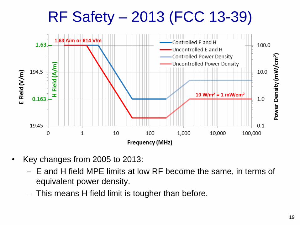
• Key changes from 2005 to 2013:
– E and H field MPE limits at low RF become the same, in terms of
equivalent power density.
– This means H field limit is tougher than before.
RF Safety – 2013 (FCC 13-39)
19
10 W/m2 = 1 mW/cm2
1.63 A/m or 614 V/m

Far-field WPT has limitations but has applications
Very low power devices or sensor network, where efficiency
and safety would not be concerns
High power space, military, or industrial applications not
sensitive to cost
However, when it comes to consumer applications such as
charging cellular phones, laptops, and other portable
electronic devices, or even electric cars, far-field WPT is
not suitable because of efficiency and safety.
Near-field WPT is a better choice.
Low-frequency magnetic field can be used to allow higher
equivalent plane wave power density.
20
From Far-Field WPT to Near-Field WPT

Many of them are wireless devices, but they are not completely
wireless – still many power chargers and many cables!
A traveler knows the pain of carrying all these chargers.
Standardized USB charging connector could be a solution but
there are still proprietary connectors/chargers, and wires are still
there.
Wireless power is the ultimate solution – cut the last cable.
Demand driven by portable devices…
21
http://www.treehugger.com/2009/10/25-week/ http://community.crutchfield.com/blogs/av_tips/archi
ve/2008/07/22/monster-power-outlets-to-go-went-
well.aspx

Near-field Wireless Power Charger
Magnetic coupling
Higher efficiency than far-field
Low frequency electronics high efficiency
Less safety concern
22
WiPower
Witricity
Qualcomm WiPowerTM
PowerMat

Types of Near-Field Wireless Power
23
• Magnetic resonance
• Magnetic field
• Four coils
Science Express 2007 by MIT team
Murata 10 W module for charging iPad
• Capacitive coupling
• Electric field
• Inductive coupling, or magnetic coupling
• Magnetic field
• Strong coupling or weak coupling
• Many technologies and many companies
The following discussions will focus on magnetic coupling.

Inductive Coupling
Magnetic coupling to transfer power
has been around for quite many
years. Rechargeable electric
toothbrush is an example.
So what’s the challenge?
It uses spilt ferrite core to achieve
strong coupling
It requires careful alignment
To have higher power transfer with
lateral movement freedom yet
keeping high efficiency and without
using ferrite core, is a challenge.
Charging multiple devices is
another major challenge.
24
Electric toothbrush

25
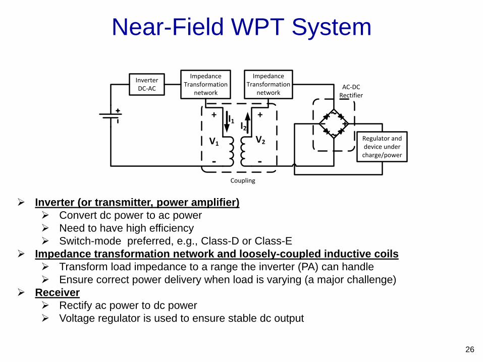
Near-Field WPT System
26
Inverter (or transmitter, power amplifier)
Convert dc power to ac power
Need to have high efficiency
Switch-mode preferred, e.g., Class-D or Class-E
Impedance transformation network and loosely-coupled inductive coils
Transform load impedance to a range the inverter (PA) can handle
Ensure correct power delivery when load is varying (a major challenge)
Receiver
Rectify ac power to dc power
Voltage regulator is used to ensure stable dc output
InverterDC-AC
Regulator anddevice under
charge/power
ImpedanceTransformation
network
ImpedanceTransformation
network
Coupling
AC-DCRectifier
I2
I1
V1 V2
++
--

Difference Between Far-Field WPT and Near-Field WPT
27
Because it is near-field coupling, transmitter and receiver are no longer
decoupled. Transmitter efficiency depends on the coupling and the load at
receiver.
Because the coupling and the receiver load might change (vs. time or location),
the transmitter will see a variable load.
Essentially, this becomes designing a power amplifier with variable load!
Need complete system optimization. Optimizing coil-to-coil coupling efficiency
alone will not result in an optimized system efficiency.
InverterDC-AC
Regulator anddevice under
charge/power
ImpedanceTransformation
network
ImpedanceTransformation
network
Coupling
AC-DCRectifier
I2
I1
V1 V2
++
--
Far-Field WPT Near-Field WPT
system efficiency = (ηT)x (ηC)x (ηR) system efficiency = ?

Near-Field WPT – Loosely Coupled
High power (295 W) delivery with high
end-to-end system efficiency (>75%)
Class-E transmitter operating @ 134 kHz
Varying location of RX on TX Power
delivery variation 5%
Coupling coefficient ~ 0.37 (>0.25 to avoid
TX heating)
CshuntCout
ACCtx Crx Rload
ZrxZtxcoil
Ztx
Lout
LDC
Transformation network
Z. N. Low, R. A. Chinga, R. Tseng, and J. Lin, "Design and Test of a
High-Power High-Efficiency Loosely Coupled Planar Wireless Power
Transfer System,“ IEEE Transactions on Industrial Electronics, Vol. 56,
No. 5, pp. 1801-1812, May 2009.
TX coil 21cmx21cm
RX coil 13cmx13cm
Separation 1cm
28

2
2
2
84
0.5768
CCout ClassE
CC
VP
R
V
R
2
2
2
2
0.2026
CCout ClassD
CC
VP
R
V
R
For the same … Compare … Ratio (Class-E/Class-D)
Supply voltage Power delivery 2.847
Power delivery Supply voltage 0.593
Power delivery Drain voltage stress 2.112
Supply voltage Drain voltage stress 3.562
Compared to Class-D:
Simple single transistor topology
Single gate drive instead of out-of-phase gate drive
Higher power delivery with same supply voltage
Disadvantage: Higher device stress
Why Class-E?
29

Impedance Transformation Network
30
Ctx Crx Ctx Crx
CrxCtx Ctx Crx
Series-Series
Topology
Series-Parallel
Topology
Parallel-Series
Topology
Parallel-Parallel
Topology
Capacitors are preferred over inductors because they are smaller and less lossy. Also achieve resonance to increase efficiency.
Single element impedance transformation is used to achieve low component count and simplicity. More complex network can be used, but loss may increase.
Purpose of the network is to achieve high efficiency coupling between the coils desirable phase response/power delivery trend.

Receiver Capacitor in Series
31
2 212
22
22
2 212 22
11 22
22
2 212
112
2 212
11
11
rxtxcoil
rx rx
rx
rx rx
rxtxcoil
rx
txcoilrx
txcoilrx
M RZ
R M X
M M Xj M
R M X
M RZ j M
R
MZ j M
R
AZ j MR
1. A is small due to loose coupling
2. Ztxcoil will be small unless • Operating frequency is high, or • Receiver coil is large
3. Resulting in high loss across parasitic resistance of transmitting coil and LC filter network.

Receiver Capacitor in Parallel
32
2
2 2 2 2 2 21 1rx rx rx
rx rx rx rx
rxR C RZ jC R C R
1. Resistance Rrx is “compressed” by a factor of 1/(1 + 2Crx
2Rrx2), the equivalent resistance
Rrx decreases with increasing load resistance.
2. The reactive term decreases nonlinearly from null with increasing load resistance with an asymptote of -1/ Crx. This is used to compensate the receiving coil inductance.

Impedance Transformation Network
33
Ctx Crx Ctx Crx
CrxCtx Ctx Crx
Series-Series
Topology
Series-Parallel
Topology
Parallel-Series
Topology
Parallel-Parallel
Topology
On receiver side, parallel capacitor is better than series capacitor. On the transmitter side, either series or parallel topology can be used. Crx is selected to reflect maximum resistance looking into the transmitting coil. If the
variation of resistance looking into the transmitter coil is too large, it is preferred that a parallel capacitor is used on transmitter side to further compress the resistance Parallel-Parallel Topology
Series-Parallel Topology has an advantage: Ctx can be absorbed into Cout (reducing one component)

TX Coil Design for Uniform Field
34
Rectangular spiral of N turns
Spacing increases
approaching the center.
Width of turn n to turn n+1
related by ratio f
Corners blunted by fraction Δ
to reduce field peaks
Coil is fully described by
length, width, N, Δ, k.
kNnNf )/)1(1(1
J. J. Casanova, Z. N. Low, J. Lin, R. Tseng, "Transmitting Coil Achieving Uniform Magnetic
Field Distribution for Planar Wireless Power Transfer System," Proceedings of IEEE Radio
and Wireless Symposium, pp. 530-533, January 2009.

Magnetic Field Distribution
35
Calculation (Magnetic Quasi-Static) Measurement
Voltage (mV) on the field probe H (A/m) based on 1 A current on coil

RFIC Inductors – a comparison
0
5
10
15
20
25
0 1 2 3 4 5 6 7 8 9 10
Ind
uc
tan
ce
(n
H),
Q
Frequency (GHz)
LDE1
LDE2
LDE3
LDE4
LDE5
QDE1
QDE2
QDE3
QDE4
QDE5
0
5
10
15
20
25
0 1 2 3 4 5 6 7 8 9 10
Ind
uc
tan
ce
(n
H),
Q
Frequency (GHz)
L1
L2
L3
L4
L5
L1
L2
L3
L4
L5
simulation without
current crowding effect measured
Q Q
current density
36
L L
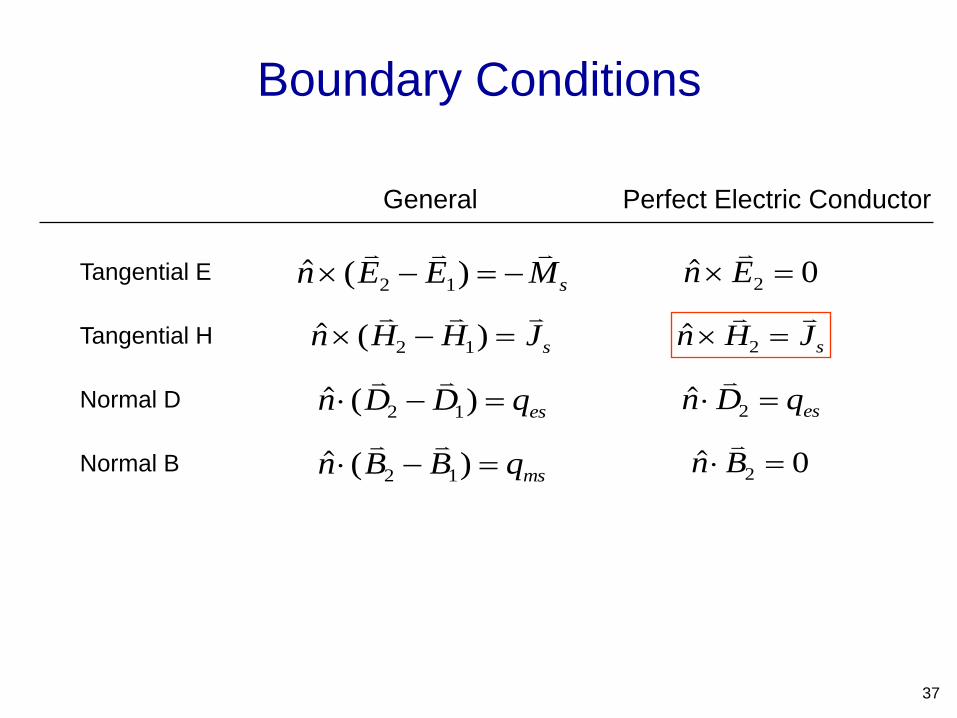
Tangential E
Tangential H
Normal D
Normal B
General Perfect Electric Conductor
( )n E E Ms
2 1
( )n H H Js
2 1
( )n D D qes
2 1
( )n B B qms
2 1
n E
2 0
n H Js
2
n D qes
2
n B
2 0
Boundary Conditions
37
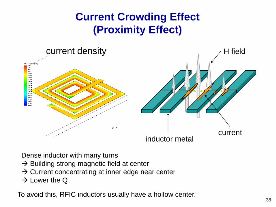
Current Crowding Effect
(Proximity Effect)
H field
current inductor metal
current density
Dense inductor with many turns
Building strong magnetic field at center
Current concentrating at inner edge near center
Lower the Q
To avoid this, RFIC inductors usually have a hollow center. 38

Transmitter 20 cm x 20 cm, 13 turns
Receiver 6 cm x 8 cm, 6 turns
100 strand/40 AWG Litz wire for both coils
Operating frequency 240 kHz, Vcc 12 V
Peak delivered dc power = 11.8 W
Peak coupling efficiency = 88.4%. Peak dc-to-dc efficiency = 80.9%
Power delivery variation vs. location < 10%
10 W System with 80% Efficiency
39
9 W
9.3 W
8.7 W

Wireless Laptop Charging Station Dell Vostro 1310 laptop
Battery removed from laptop
Power from the wireless power
receiver only
Total power required: 32 W
TX coil size: 35 cm x 25 cm
RX coil size: 20 cm x 12 cm
40
J. A. Taylor, Z. N. Low, J. J. Casanova, J. Lin, "A Wireless Power Station for Laptop Computers," Proceedings
of IEEE Radio and Wireless Symposium, pp. 625-628, January 2010
LCD

Transmitter Design
41
TX coil is embedded into the desktop
(blue dashed outline).
Two parallel overlapping coils created
uniform magnetic field distribution.
TX coil size: 35 cm x 25 cm
TX board size: 5 cm x 17 cm
Operate at 240 kHz
High-power Class-E Inverter
Low-power control circuit

Measurement Result
Better than 50% for power
above 15 W.
Peak efficiency near 60%.
Total system efficiency includes
the receiver regulator, detection
and control circuitry, with
respect to the power delivered
to the laptop.
Voltage regulator conversion
efficiency: 90%
Class E amplifier drain
efficiency: > 90% for most load
conditions
Since the laptop generates more heat than
the wireless power receiver, temperature
increase is not observed after high power
operation of more than 2 hours.
Most of the heat is generated at the ferrites
and voltage regulator which can be easily
dissipated to the environment
42

Software Control and Load Detection
Initial start-up: no load state.
Supply current and coil voltage sampled by A/D converter
determine the system state.
If no load is detected, the system enters into a low duty cycle state to save power by turning off the
system most of the time and only probes the system once every two seconds.
For simplicity, the fault state (foreign object detection) is only considered if a piece of metallic or
magnetic material of significant size is placed in the vicinity of the transmitting coil. 43
Start
Up
No
Load
FaultLaptop
Detected
Laptop
OnFatal
Fault
Laptop remains
powered on
System lockout
Fault detected
Fault counter > 10
Fault detected
Fault counter < 10
Laptop
removed
Laptop
powered on
Fault detected
Laptop
detectedLaptop not
powered on
Fault rectified
Laptop
powered off
System
initialized

Load Detection
44
Z. N. Low, J. Casanova, P. Maier, J. Taylor, R. A. Chinga, J. Lin, "Method of Load/Fault Detection for Loosely Coupled
Planar Wireless Power Transfer System with Power Delivery Tracking," IEEE Transactions on Industrial Electronics, vol.
57, no. 4, pp. 1478-1486, April 2010

Load/Fault Detection
45
Conductive or magnetic objects at the vicinity of
the transmitting coil:
Affect self-inductance of the transmitting coil.
ZVS/ZDS operation does not hold.
Need to protect the transmitter from damage due
to over-voltage and excessive heating.
Large amount of
metallic objects on
transmitting coil
Transmitter without
shielding placed on top
of metallic object
Transmitter flipped
over and placed on
top of metallic object

Load/Fault Detection Scheme
46
Cshunt
Cout
Crx Rload
Lout
LDC
Transformation network
Rdivider1
Rdivider2
Cvcoil
Amplifiersupply current
Buffercoil voltage
a11
a22
3a3
b15
Vcc1
0
GND
0
Micro-controller
Rsense_DC
VccIn 1
In 2
Out 1
1
2
3
4In 3
Amplifiercoil current
Rsense_AC
Dvcoil
Rvcoil
1
3
2
Coil Voltage
Supply Current
Coil Current
All detections except #3 are done in DC so that a low speed ADC can be used.
Load/Fault Detection Scheme #1
47
Cshunt
Cout
Crx Rload
Lout
LDC
Transformation network
Rdivider1
Rdivider2
Cvcoil
Amplifiersupply current
Buffercoil voltage
a11
a22
3a3
b15
Vcc1
0
GND
0
Micro-controller
Rsense_DC
VccIn 1
In 2
Out 1
1
2
3
4In 3
Amplifiercoil current
Rsense_AC
Rvcoil
Dvcoil
1 Coil Voltage
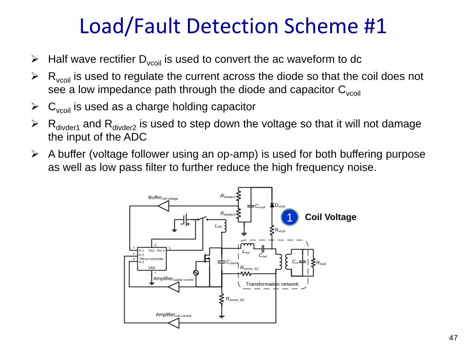
Half wave rectifier Dvcoil is used to convert the ac waveform to dc
Rvcoil is used to regulate the current across the diode so that the coil does not
see a low impedance path through the diode and capacitor Cvcoil
Cvcoil is used as a charge holding capacitor
Rdivder1 and Rdivder2 is used to step down the voltage so that it will not damage
the input of the ADC
A buffer (voltage follower using an op-amp) is used for both buffering purpose
as well as low pass filter to further reduce the high frequency noise.
Load/Fault Detection Scheme #2
48
Cshunt
Cout
Crx Rload
Lout
LDC
Transformation network
Rdivider1
Rdivider2
Cvcoil
Amplifiersupply current
Buffercoil voltage
a11
a22
3a3
b15
Vcc1
0
GND
0
Micro-controller
Rsense_DC
VccIn 1
In 2
Out 1
1
2
3
4In 3
Amplifiercoil current
Rsense_AC
Rvcoil
Dvcoil
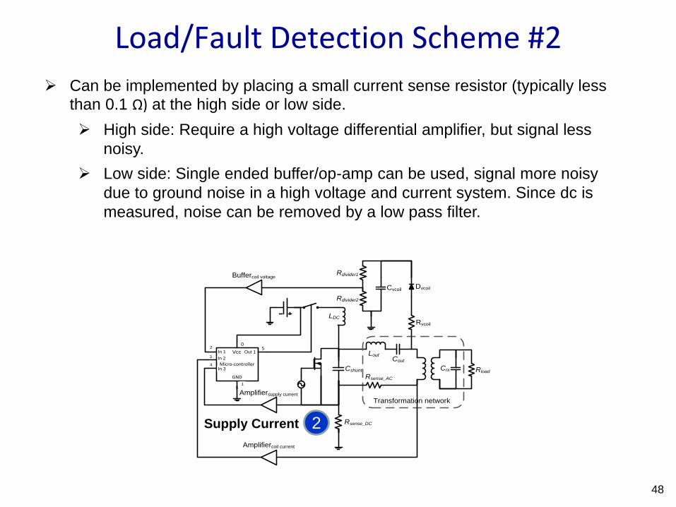
Can be implemented by placing a small current sense resistor (typically less than 0.1 Ω) at the high side or low side.
High side: Require a high voltage differential amplifier, but signal less
noisy.
Low side: Single ended buffer/op-amp can be used, signal more noisy
due to ground noise in a high voltage and current system. Since dc is
measured, noise can be removed by a low pass filter.
2 Supply Current

Load/Fault Detection Scheme #3
49
Cshunt
Cout
Crx Rload
Lout
LDC
Transformation network
Rdivider1
Rdivider2
Cvcoil
Amplifiersupply current
Buffercoil voltage
a11
a22
3a3
b15
Vcc1
0
GND
0
Micro-controller
Rsense_DC
VccIn 1
In 2
Out 1
1
2
3
4In 3
Amplifiercoil current
Rsense_AC
Rvcoil
Dvcoil
Can be implemented by placing a small current sense resistor (typically less than 0.1 Ω) at the high side or low side, or using a current sense transformer.
High side: Requires an extremely high voltage (>100 V) high speed
differential amplifier, but signal less noisy.
Low side: Single ended buffer/op-amp can be used, signal more noisy
due to ground noise in a high voltage and current system. Noise cannot
be remove because of ac measurement.
Current sense transformer are typically bulky and have frequency
response less than 100 kHz. In addition, the current sense transformer
will pick up the high voltage and current signals on the PCB as noise.
3
Coil Current

Challenge: Charging Multiple Receivers
50
Blue: TX coil (large)
Red: RX coil (small)
Multiple TX coils (in parallel) transferring power to multiple RX coils

Charging Two Receivers
51
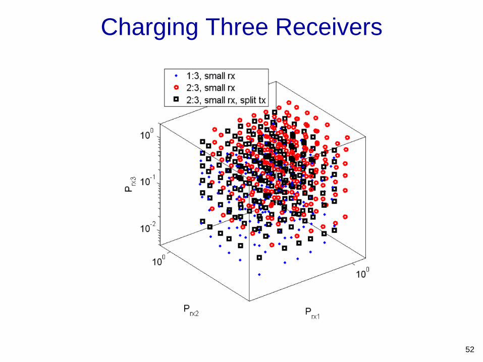
Charging Three Receivers
52

Challenge of Multiple Variable Loads
53
maximum received power and maximum efficiency
J. Casanova, Z. N. Low, J. Lin, "A Loosely Coupled Planar Wireless Power System for Multiple Receivers,"
IEEE Transactions on Industrial Electronics, Vol. 56, No. 8, pp. 3060-3068, August 2009
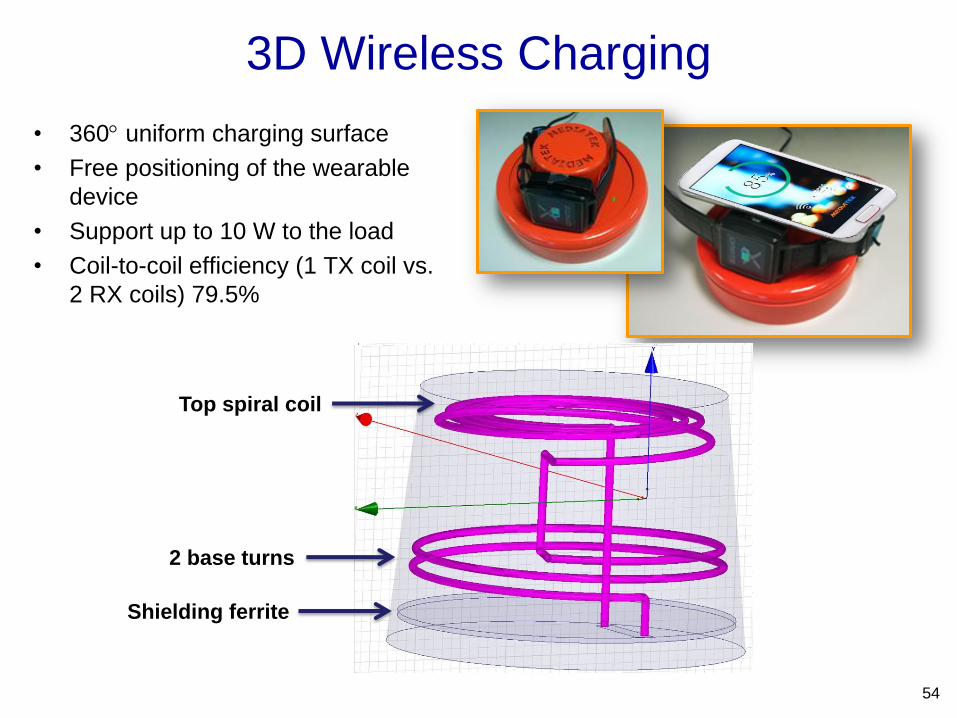
3D Wireless Charging
• 360 uniform charging surface
• Free positioning of the wearable
device
• Support up to 10 W to the load
• Coil-to-coil efficiency (1 TX coil vs.
2 RX coils) 79.5%
54
2 base turns
Top spiral coil
Shielding ferrite

3D Wireless Charging: TX Coil
• Cell Phone charging area
– Reduce central turns to have uniform magnetic field
• Ls= 1.3 mH @6.78 MHz, Q= 250
Uniform magnetic field
within charging area Strong magnetic field
at center

3D Wireless Charging: TX Coil
• Wearable device charging area
56
R.-C. Kuo, P. Riehl, Anand Satyamoorthy, W. Plumb, P. Tustin, J. Lin, "A 3D Resonant Wireless Charger for
a Wearable Device and a Mobile Phone," IEEE Wireless Power Transfer Conference, May 2015.

A Mid-range WPT System
• Two 1 m x 1 m coils separated by 1 m
• Driven by full-bridge Class-D amplifier
• Frequency: 508.5 kHz
57

Design Equations
58
At resonance,
𝜂𝑀𝐴𝑋 =𝛼2
1 + 1 + 𝛼22 𝛼 = 𝑘 𝑄1𝑄2 𝑄1 =
𝜔𝐿1𝑅1
𝑄2 =𝜔𝐿2𝑅2

Mid-range WPT System Test Result
59

• Industry alliances for near-field wireless charging
– Wireless Power Consortium (Qi):
est. Dec. 2008, 226 members (11/2015)
– AirFuel Alliance (195 members, 11/2015)
combining
• Alliance for Wireless Power (A4WP):
est. 2012, 140 members (4/2015)
• Power Matters Alliance (PMA)
est. 2012, 68 members (4/2015)
• A unified standard like IEEE 802.11 (WiFi) would be better
– Compatibility
– Unlicensed operation
– Wireless communications interface for authentication of wireless power
transfer
Commercialization and Standardization
60

Tester
• Signals can be transmitted wirelessly, why not do the same for power?
Cut the last wire to the chip!
• A chip mounted on PCB without bond wire or flip-chip bump
• Both operating dc voltage and power consumption of IC chips for
mobile devices continue to decrease, making this possible in the
future.
• Testing, packaging, and system integration of IC chips in the future will
be very different.
Wireless-Powered IC Chips
61
IC
Conveyor belt
IC IC
• No wafer probing
• No contact
• Faster throughput

• The development of wireless power and other wireless
technologies benefited from semiconductor technology.
• In return, wireless power may revolutionize IC testing and
packaging in semiconductor industry.
Future Chip-Scale Wireless Power
62
IoT (Internet of Things) IoC (Internet of Chips)

Conclusion
o Wireless Power in the 21st Century: a mix of both long
range and short range, both near field and far field
o Far-field wireless power
o Long range
o Lower efficiency
o Space/military, ultra low power devices, sensor network
o Energy harvesting
o Near-field wireless power
o Short range – less safety concern
o Higher efficiency
o Wireless charging EV, OLEV, personal equipment, IoT
o Frequency: kHz, MHz, or GHz
o Large scale to small scale
o OLEV, EV, UAV, laptop, mobile phone, IC chip, … 63


![[XLS] · Web viewAL3Z AU2Z WPT-1090 BL3Z F4AZ 15A416 9E5Z K WPT-1161 8L3Z F5SZ 9F479 UB WPT-992 8C2Z BHAB WPT-1147 F5TZ AU5Z WPT-1089 16611B08 16611B09 BC3Z F5CZ XF3Z WPT-1001 NUB](https://static.fdocuments.in/doc/165x107/5af9707e7f8b9aac248e66a3/xls-viewal3z-au2z-wpt-1090-bl3z-f4az-15a416-9e5z-k-wpt-1161-8l3z-f5sz-9f479-ub.jpg)