Harish Nairand Rajmohan Panda global - Journal of Global Health - Home
Upload
bernard-wadeCategory
view
216download
1
Wireless Networks Spring 2005
Antennas & PropagationSignal Encoding
CSG 250Spring 2005
Rajmohan Rajaraman

Wireless Networks Spring 2005
IntroductionAn antenna is an electrical conductor or
system of conductorso Transmission - radiates electromagnetic energy
into spaceo Reception - collects electromagnetic energy
from spaceIn two-way communication, the same
antenna can be used for transmission and reception

Wireless Networks Spring 2005
Radiation Patterns Radiation pattern
o Graphical representation of radiation properties of an antenna
o Depicted as two-dimensional cross section Beam width (or half-power beam width)
o Measure of directivity of antennao Angle within which power radiated is at least half of that
in most preferred direction
Reception patterno Receiving antenna’s equivalent to radiation pattern
Omnidirectional vs. directional antenna

Wireless Networks Spring 2005
Types of Antennas Isotropic antenna (idealized)
o Radiates power equally in all directions
Dipole antennaso Half-wave dipole antenna (or Hertz antenna)o Quarter-wave vertical antenna (or Marconi antenna)
Parabolic Reflective Antenna o Used for terrestrial microwave and satellite applicationso Larger the diameter, the more tightly directional is the
beam

Wireless Networks Spring 2005
Antenna Gain
Antenna gaino Power output, in a particular direction,
compared to that produced in any direction by a perfect omnidirectional antenna (isotropic antenna)
Expressed in terms of effective areao Related to physical size and shape of antenna

Wireless Networks Spring 2005
Antenna Gain Relationship between antenna gain and effective
area
• G = antenna gain
• Ae = effective area
• f = carrier frequency• c = speed of light (≈ 3 x 10⁸ m/s) = carrier wavelength
2
2
2
44
c
AfAG ee π
π
==

Wireless Networks Spring 2005
Propagation Modes
Ground-wave propagationSky-wave propagationLine-of-sight propagation

Wireless Networks Spring 2005
Ground Wave Propagation

Wireless Networks Spring 2005
Ground Wave Propagation
Follows contour of the earthCan Propagate considerable distancesFrequencies up to 2 MHzExample
o AM radio

Wireless Networks Spring 2005
Sky Wave Propagation

Wireless Networks Spring 2005
Sky Wave Propagation Signal reflected from ionized layer of atmosphere
back down to earth Signal can travel a number of hops, back and forth
between ionosphere and earth’s surface Reflection effect caused by refraction Examples
o Amateur radioo CB radio

Wireless Networks Spring 2005
Line-of-Sight Propagation

Wireless Networks Spring 2005
Line-of-Sight Propagation Transmitting and receiving antennas must be
within line of sighto Satellite communication – signal above 30 MHz not
reflected by ionosphereo Ground communication – antennas within effective line of
site due to refraction Refraction – bending of microwaves by the
atmosphereo Velocity of electromagnetic wave is a function of the
density of the mediumo When wave changes medium, speed changeso Wave bends at the boundary between mediums

Wireless Networks Spring 2005
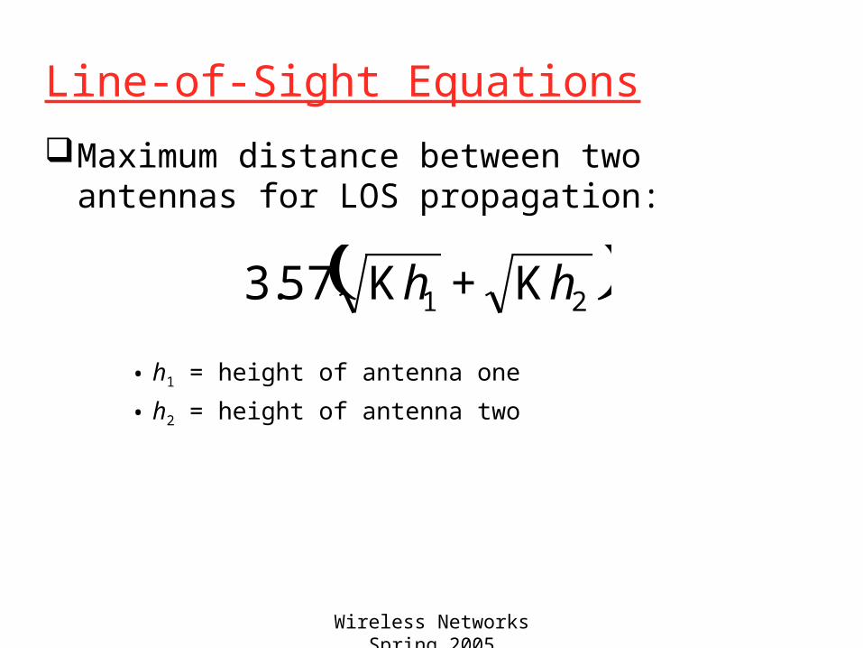
Line-of-Sight Equations
Optical line of sight
Effective, or radio, line of sight
• d = distance between antenna and horizon (km)
• h = antenna height (m)• K = adjustment factor to account for
refraction, rule of thumb K = 4/3
hd 57.3=
hd Κ= 57.3
Wireless Networks Spring 2005
Line-of-Sight Equations
Maximum distance between two antennas for LOS propagation:
• h1 = height of antenna one
• h2 = height of antenna two
( )2157.3 hh Κ+Κ

Wireless Networks Spring 2005
LOS Wireless Transmission ImpairmentsAttenuation and attenuation distortionFree space lossNoiseAtmospheric absorptionMultipathRefractionThermal noise

Wireless Networks Spring 2005
Attenuation Strength of signal falls off with distance over
transmission medium Attenuation factors for unguided media:
o Received signal must have sufficient strength so that circuitry in the receiver can interpret the signal
o Signal must maintain a level sufficiently higher than noise to be received without error
o Attenuation is greater at higher frequencies, causing distortion

Wireless Networks Spring 2005
Free Space Loss Free space loss, ideal isotropic antenna
• Pt = signal power at transmitting antenna
• Pr = signal power at receiving antenna = carrier wavelength• d = propagation distance between antennas• c = speed of light (≈ 3 x 10⁸ m/s)where d and are in the same units (e.g., meters)
( ) ( )2
2
2
2 44
c
fdd
P
P
r
t π
λ
π==

Wireless Networks Spring 2005
Free Space Loss
Free space loss equation can be recast:
⎟⎠
⎞⎜⎝
⎛==πd
P
PL
r
tdB
4log20log10
( ) ( ) dB 98.21log20log20 ++−= dλ
( ) ( ) dB 56.147log20log204
log20 −+=⎟⎠
⎞⎜⎝
⎛= df
c
fdπ

Wireless Networks Spring 2005
Free Space Loss Free space loss accounting for gain of antennas
• Gt = gain of transmitting antenna
• Gr = gain of receiving antenna
• At = effective area of transmitting antenna
• Ar = effective area of receiving antenna
( ) ( ) ( ) ( )trtrtrr
t
AAf
cd
AA
d
GG
d
P
P2
22
2
224===
λ
λ
π

Wireless Networks Spring 2005
Free Space Loss
Free space loss accounting for gain of other antennas can be recast as
( ) ( ) ( )rtdB AAdL log10log20log20 −+= λ
( ) ( ) ( ) dB54.169log10log20log20 +−+−= rtAAdf

Wireless Networks Spring 2005
Categories of Noise
Thermal NoiseIntermodulation noiseCrosstalkImpulse Noise

Wireless Networks Spring 2005
Thermal Noise
Thermal noise due to agitation of electronsPresent in all electronic devices and
transmission mediaCannot be eliminatedFunction of temperatureParticularly significant for satellite
communication

Wireless Networks Spring 2005
Thermal NoiseAmount of thermal noise to be found in a
bandwidth of 1Hz in any device or conductor is:
• N0 = noise power density in watts per 1 Hz of bandwidth
• k = Boltzmann's constant = 1.3803 x 10⁻²³ J/K• T = temperature, in kelvins (absolute temperature)
( )W/Hz k0 TN =

Wireless Networks Spring 2005
Thermal Noise Noise is assumed to be independent of frequency Thermal noise present in a bandwidth of B Hertz
(in watts):
or, in decibel-watts
TBN k=
BTN log10 log 10k log10 ++=
BT log10 log 10dBW 6.228 ++−=

Wireless Networks Spring 2005
Noise Terminology
Intermodulation noise – occurs if signals with different frequencies share the same mediumo Interference caused by a signal produced at a
frequency that is the sum or difference of original frequencies
Crosstalk – unwanted coupling between signal paths
Impulse noise – irregular pulses or noise spikeso Short duration and of relatively high amplitudeo Caused by external electromagnetic disturbances, or
faults and flaws in the communications systemo Primary source of error for digital data transmission

Wireless Networks Spring 2005
Expression Eb/N0
Ratio of signal energy per bit to noise power density per Hertz
The bit error rate for digital data is a function of Eb/N0
o Given a value for Eb/N0 to achieve a desired error rate, parameters of this formula can be selected
o As bit rate R increases, transmitted signal power must increase to maintain required Eb/N0
TR
S
N
RS
N
Eb
k
/
00
==

Wireless Networks Spring 2005
Other Impairments
Atmospheric absorption – water vapor and oxygen contribute to attenuation
Multipath – obstacles reflect signals so that multiple copies with varying delays are received
Refraction – bending of radio waves as they propagate through the atmosphere
Wireless Networks Spring 2005
Multipath Propagation Reflection - occurs when signal encounters a
surface that is large relative to the wavelength of the signal
Diffraction - occurs at the edge of an impenetrable body that is large compared to wavelength of radio wave
Scattering – occurs when incoming signal hits an object whose size is in the order of the wavelength of the signal or less


Wireless Networks Spring 2005
Effects of Multipath PropagationMultiple copies of a signal may arrive at
different phaseso If phases add destructively, the signal level
relative to noise declines, making detection more difficult
Intersymbol interference (ISI)o One or more delayed copies of a pulse may
arrive at the same time as the primary pulse for a subsequent bit

Wireless Networks Spring 2005
Fading
Time variation of received signal power caused by changes in the transmission medium or path(s)
In a fixed environment:o Changes in atmospheric conditions
In a mobile environment:o Multipath propagation

Wireless Networks Spring 2005
Types of Fading Fast fading Slow fading Flat fading Selective fading Rayleigh fading Rician fading

Wireless Networks Spring 2005
Error Compensation Mechanisms
Forward error correctionAdaptive equalizationDiversity techniques

Wireless Networks Spring 2005
Forward Error Correction Transmitter adds error-correcting code to data
blocko Code is a function of the data bits
Receiver calculates error-correcting code from incoming data bitso If calculated code matches incoming code, no error
occurredo If error-correcting codes don’t match, receiver attempts
to determine bits in error and correct

Wireless Networks Spring 2005
Adaptive Equalization Can be applied to transmissions that carry analog
or digital informationo Analog voice or videoo Digital data, digitized voice or video
Used to combat intersymbol interference Involves gathering dispersed symbol energy back
into its original time interval Techniques
o Lumped analog circuitso Sophisticated digital signal processing algorithms

Wireless Networks Spring 2005
Diversity Techniques Space diversity:
o Use multiple nearby antennas and combine received signals to obtain the desired signal
o Use collocated multiple directional antennas Frequency diversity:
o Spreading out signal over a larger frequency bandwidtho Spread spectrum
Time diversity:o Noise often occurs in burstso Spreading the data out over time spreads the errors and
hence allows FEC techniques to work wello TDMo Interleaving

Wireless Networks Spring 2005
Signal Encoding Techniques

Wireless Networks Spring 2005
Reasons for Choosing Encoding TechniquesDigital data, digital signal
o Equipment less complex and expensive than digital-to-analog modulation equipment
Analog data, digital signalo Permits use of modern digital transmission and
switching equipment

Wireless Networks Spring 2005
Reasons for Choosing Encoding TechniquesDigital data, analog signal
o Some transmission media will only propagate analog signals
o E.g., unguided mediaAnalog data, analog signal
o Analog data in electrical form can be transmitted easily and cheaply
o Done with voice transmission over voice-grade lines

Wireless Networks Spring 2005
Signal Encoding Criteria What determines how successful a receiver will be
in interpreting an incoming signal?o Signal-to-noise ratioo Data rateo Bandwidth
An increase in data rate increases bit error rate An increase in SNR decreases bit error rate An increase in bandwidth allows an increase in
data rate

Wireless Networks Spring 2005
Comparing Encoding Schemes Signal spectrum
o With lack of high-frequency components, less bandwidth required
o With no dc component, ac coupling via transformer possible
o Transfer function of a channel is worse near band edges
Clockingo Ease of determining beginning and end of each bit
position

Wireless Networks Spring 2005
Comparing Encoding Schemes Signal interference and noise immunity
o Performance in the presence of noise
Cost and complexityo The higher the signal rate to achieve a given data rate,
the greater the cost

Wireless Networks Spring 2005
Digital Data to Analog Signals
Amplitude-shift keying (ASK)o Amplitude difference of carrier frequency
Frequency-shift keying (FSK)o Frequency difference near carrier frequency
Phase-shift keying (PSK)o Phase of carrier signal shifted


Wireless Networks Spring 2005
Amplitude-Shift Keying One binary digit represented by presence of
carrier, at constant amplitude Other binary digit represented by absence of
carrier
• where the carrier signal is Acos(2πfct)
( )⎪⎩
⎪⎨⎧
=ts( )tfA cπ2cos
0
1binary
0binary

Wireless Networks Spring 2005
Amplitude-Shift Keying
Susceptible to sudden gain changesInefficient modulation techniqueOn voice-grade lines, used up to 1200 bpsUsed to transmit digital data over optical
fiber

Wireless Networks Spring 2005
Binary Frequency-Shift Keying (BFSK) Two binary digits represented by two different
frequencies near the carrier frequency
• where f1 and f2 are offset from carrier frequency fc by equal but opposite amounts
( )⎪⎩
⎪⎨⎧
=ts( )tfA 12cos π
( )tfA 22cos π
1binary 0binary

Wireless Networks Spring 2005
Binary Frequency-Shift Keying (BFSK)Less susceptible to error than ASKOn voice-grade lines, used up to 1200bpsUsed for high-frequency (3 to 30 MHz)
radio transmissionCan be used at higher frequencies on LANs
that use coaxial cable

Wireless Networks Spring 2005
Multiple Frequency-Shift Keying (MFSK) More than two frequencies are used More bandwidth efficient but more susceptible to
error
• f i = f c + (2i – 1 – M)f d
• f c = the carrier frequency• f d = the difference frequency• M = number of different signal elements = 2 L
• L = number of bits per signal element
( ) tfAts ii π2cos= Mi ≤≤1
Wireless Networks Spring 2005
Multiple Frequency-Shift Keying (MFSK) To match data rate of input bit stream,
each output signal element is held for:Ts=LT seconds
• where T is the bit period (data rate = 1/T)
So, one signal element encodes L bits

Wireless Networks Spring 2005
Multiple Frequency-Shift Keying (MFSK)Total bandwidth required
2Mfd
Minimum frequency separation required 2fd=1/Ts
Therefore, modulator requires a bandwidth of
Wd=2L/LT=M/Ts

Wireless Networks Spring 2005
Multiple Frequency-Shift Keying (MFSK)

Wireless Networks Spring 2005
Phase-Shift Keying (PSK)
Two-level PSK (BPSK)o Uses two phases to represent binary digits
( )⎪⎩
⎪⎨⎧
=ts( )tfA cπ2cos( )ππ +tfA c2cos
1binary 0binary
⎪⎩
⎪⎨⎧
=( )tfA cπ2cos
( )tfA cπ2cos−
1binary 0binary

Wireless Networks Spring 2005
Phase-Shift Keying (PSK)
Differential PSK (DPSK)o Phase shift with reference to previous bit
• Binary 0 – signal burst of same phase as previous signal burst
• Binary 1 – signal burst of opposite phase to previous signal burst

Wireless Networks Spring 2005
Phase-Shift Keying (PSK)
Four-level PSK (QPSK)o Each element represents more than one bit
( )⎪⎪⎩
⎪⎪⎨
⎧
=ts
⎟⎠
⎞⎜⎝
⎛ +4
2cosπ
π tfA c 11
⎟⎠
⎞⎜⎝
⎛ +4
32cos
ππ tfA c
⎟⎠
⎞⎜⎝
⎛ −4
32cos
ππ tfA c
⎟⎠
⎞⎜⎝
⎛ −4
2cosπ
π tfA c
01
00
10

Wireless Networks Spring 2005
Phase-Shift Keying (PSK)
Multilevel PSKo Using multiple phase angles with each angle having
more than one amplitude, multiple signals elements can be achieved
• D = modulation rate, baud• R = data rate, bps• M = number of different signal elements = 2L
• L = number of bits per signal element
M
R
L
RD
2log==

Wireless Networks Spring 2005
Performance
Bandwidth of modulated signal (BT)
o ASK, PSK BT=(1+r)R
o FSK BT=2DF+(1+r)R
• R = bit rate• 0 < r < 1; related to how signal is filtered
• DF = f2-fc=fc-f1

Wireless Networks Spring 2005
Performance
Bandwidth of modulated signal (BT)
o MPSK
o MFSK
• L = number of bits encoded per signal element• M = number of different signal elements
RM
rR
L
rBT ⎟⎟
⎠
⎞⎜⎜⎝
⎛ +=⎟
⎠
⎞⎜⎝
⎛ +=
2log11
( )R
M
MrBT ⎟⎟
⎠
⎞⎜⎜⎝
⎛ +=
2log
1

Wireless Networks Spring 2005
Quadrature Amplitude Modulation
QAM is a combination of ASK and PSKo Two different signals sent simultaneously on
the same carrier frequency
( ) ( ) ( ) tftdtftdts cc ππ 2sin2cos 21 +=

Quadrature Amplitude Modulation

Wireless Networks Spring 2005
Analog Data to Analog Signal
Modulation of digital signalso When only analog transmission facilities are
available, digital to analog conversion required
Modulation of analog signalso A higher frequency may be needed for effective
transmissiono Modulation permits frequency division
multiplexing

Wireless Networks Spring 2005
Mopdulation Techniques
Amplitude modulation (AM)Angle modulation
o Frequency modulation (FM)o Phase modulation (PM)

Wireless Networks Spring 2005
Amplitude Modulation
( ) ( )[ ] tftxnts ca π2cos1+=
Amplitude Modulation
• cos2πfct = carrier• x(t) = input signal• na = modulation index (< 1)
– Ratio of amplitude of input signal to carrier
o a.k.a double sideband transmitted carrier (DSBTC)


Wireless Networks Spring 2005
Amplitude Modulation
Transmitted power
• Pt = total transmitted power in s(t)
• Pc = transmitted power in carrier
⎟⎟⎠
⎞⎜⎜⎝
⎛+=
21
2a
ct
nPP

Wireless Networks Spring 2005
Single Sideband (SSB) Variant of AM is single sideband (SSB)
o Sends only one sidebando Eliminates other sideband and carrier
Advantageso Only half the bandwidth is requiredo Less power is required
Disadvantageso Suppressed carrier can’t be used for synchronization
purposes

Wireless Networks Spring 2005
Angle Modulation
Angle modulation
Phase modulationo Phase is proportional to modulating signal
• np = phase modulation index
( ) ( )[ ]ttfAts cc φπ += 2cos
( ) ( )tmnt p=φ

Wireless Networks Spring 2005
Angle Modulation
Frequency modulationo Derivative of the phase is proportional to
modulating signal
• nf = frequency modulation index
( ) ( )tmnt f='φ

Wireless Networks Spring 2005
Angle Modulation
Compared to AM, FM and PM result in a signal whose bandwidth:o is also centered at fc
o but has a magnitude that is much different
Thus, FM and PM require greater bandwidth than AM

Wireless Networks Spring 2005
Angle Modulation
Carson’s rule
where
The formula for FM becomes
( )BBT 12 += β
BFBT 22 +Δ=
FMfor
PMfor
2⎪⎩
⎪⎨⎧
=Δ=
BAn
BF
An
mf
mp
πβ

Wireless Networks Spring 2005
Analog Data to Digital Signal
Digitization: Often analog data are converted to digital form
Once analog data have been converted to digital signals, the digital data:o can be transmitted using NRZ-Lo can be encoded as a digital signal using a code
other than NRZ-Lo can be converted to an analog signal, using
previously discussed techniques

Wireless Networks Spring 2005
Analog data to digital signal
Pulse code modulation (PCM)Delta modulation (DM)
Wireless Networks Spring 2005
Pulse Code ModulationBased on the sampling theoremEach analog sample is assigned a binary
codeo Analog samples are referred to as pulse
amplitude modulation (PAM) samplesThe digital signal consists of block of n bits,
where each n-bit number is the amplitude of a PCM pulse


Wireless Networks Spring 2005
Pulse Code ModulationBy quantizing the PAM pulse, original
signal is only approximatedLeads to quantizing noiseSignal-to-noise ratio for quantizing noise
Thus, each additional bit increases SNR by 6 dB, or a factor of 4
dB 76.102.6dB 76.12log20SNR dB +=+= nn

Wireless Networks Spring 2005
Delta Modulation
Analog input is approximated by staircase functiono Moves up or down by one quantization level ()
at each sampling interval
The bit stream approximates derivative of analog signal (rather than amplitude)o 1 is generated if function goes upo 0 otherwise

Delta Modulation

Wireless Networks Spring 2005
Delta ModulationTwo important parameters
o Size of step assigned to each binary digit ()o Sampling rate
Accuracy improved by increasing sampling rateo However, this increases the data rate
Advantage of DM over PCM is the simplicity of its implementation