
Wireless Networks (PHY): Design for Diversity Y. Richard Yang 9/20/2012.
52
Wireless Networks (PHY): Design for Diversity Y. Richard Yang 9/20/2012
-
Upload
julianna-abigail-garrett -
Category
Documents
-
view
217 -
download
1
Transcript of Wireless Networks (PHY): Design for Diversity Y. Richard Yang 9/20/2012.

Wireless Networks (PHY): Design for Diversity
Y. Richard Yang
9/20/2012

2
Outline
Admin and recap
Design for diversity

3
Admin
Assignment 1 questions
Assignment 1 office hours Thursday 3-4 @ AKW 307A

4
Channel characteristics change over location, time, and frequency
small-scale fading
Large-scalefading
time
power
Recap: Wireless Channels
path loss
log (distance)
Received Signal Power (dB)
frequency

5
Outline
Recap Wireless channels Physical layer design
design for flat fading• how bad is flat fading?• diversity to handle flat fading

6
Recap: Impact of Channel on Decisions

7
Recap: Impact of Channel
Averaged out over h,
at high SNR.
Assume h is Gaussian random:

8
Recap: Impacts of Channel
static channel
flat fading channel
9
Outline
Recap Wireless channels Physical layer design
design for flat fading• how bad is flat fading?• diversity to handle flat fading
10
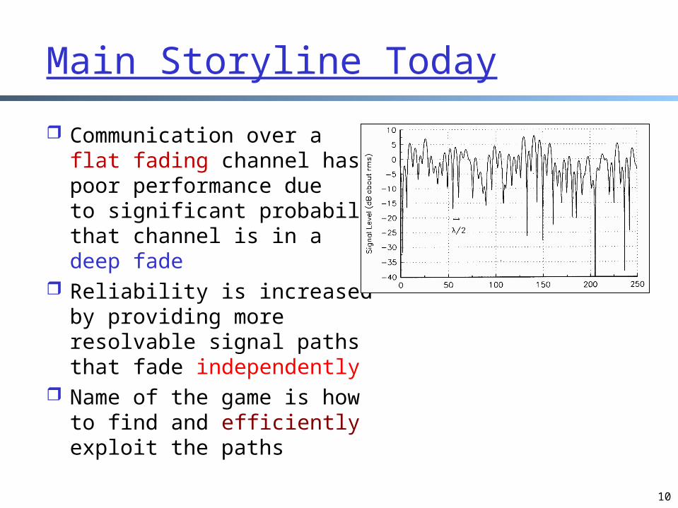
Main Storyline Today
Communication over a flat fading channel has poor performance due to significant probability that channel is in a deep fade
Reliability is increased by providing more resolvable signal paths that fade independently
Name of the game is how to find and efficiently exploit the paths

11
Where to Find Diversity?
Time: when signal is bad at time t, it may not be bad at t+t
Space: when one position is in deep fade, another position may be not
Frequency: when one frequency is in deep fade (or has large interference), another frequency may be in good shape
2121 22
dd
c
ddf

12
Outline
Recap Wireless channels Physical layer design
design for flat fading• how bad is flat fading?• diversity to handle flat fading
– time

13
Time Diversity Time diversity can be obtained by interleaving
and coding over symbols across different coherent time periods
interleave
coherencetime

14
1 2 3 4 5 6 7 8
935-960 MHz124 channels (200 kHz)downlink
890-915 MHz124 channels (200 kHz)uplink
frequ
ency
time
GSM TDMA frame
GSM time-slot (normal burst)
4.615 ms
546.5 µs577 µs
tail user data TrainingSguardspace S user data tail
guardspace
3 bits 57 bits 26 bits 57 bits1 1 3
Example: GSM Time Structure
S: indicates data or control

15
Example: GSM Bit Assignments
Amount of time diversity limited by delay constraint and how fast channel varies
In GSM, delay constraint is 40 ms (voice) To get better diversity, needs faster moving vehicles
!

16
Simplest Code: Repetition
After interleaving over L coherence time periods,
Le SNRP
1

17
Performance
Le SNRP
1

18
Beyond Repetition Coding
Repetition coding gets full diversity, but sends only one symbol every L symbol times
We can use other codes, e.g. Reed-Solomon code

19
Outline
Recap Wireless channels Physical layer design
design for flat fading• how bad is flat fading?• diversity to handle flat fading
– time– space

20
Space Diversity: Antenna
Receive Transmit Both

21
User Diversity: Cooperative Diversity
Different users can form a distributed antenna array to help each other in increasing diversity
Interesting characteristics: users have to exchange information and
this consumes bandwidth broadcast nature of the wireless medium
can be exploited we will revisit the issue later in the course
22
Outline
Recap Wireless channels Physical layer design
design for flat fading• how bad is flat fading?• diversity to handle flat fading
– time– space– frequency
212
1'
dd
cff

23
Discrete changes of carrier frequency sequence of frequency changes determined via pseudo
random number sequence used in 802.11, GSM, etc
Co-inventor: Hedy Lamarr patent# 2,292,387
issued on August 11, 1942 intended to make radio-guided
torpedoes harder for enemies to detect or jam
used a piano roll to change between 88 frequencies
Sequential Frequency Diversity: FHSS (Frequency Hopping Spread Spectrum)
http://en.wikipedia.org/wiki/Hedy_Lamarr

24
Two versions slow hopping: several user bits per frequency fast hopping: several frequencies per user bit
Sequential Frequency Diversity: FHSS (Frequency Hopping Spread Spectrum)
user data
slowhopping(3 bits/hop)
fasthopping(3 hops/bit)
0 1
tb
0 1 1 t
f
f1
f2
f3
t
td
f
f1
f2
f3
t
td
tb: bit period td: dwell time
25
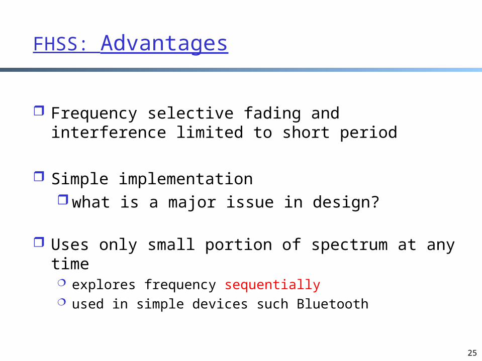
Frequency selective fading and interference limited to short period
Simple implementation what is a major issue in design?
Uses only small portion of spectrum at any time explores frequency sequentially used in simple devices such Bluetooth
FHSS: Advantages

26
Bluetooth Design Objective
Design objective: a cable replacement technology 1 Mb/s
range 10+ meters
single chip radio + baseband (means digital part)
• low power • low price point (target price $5 or lower)

27
Bluetooth Architecture

28
Bluetooth Radio Link
Bluetooth shares the same freq. range as 802.11 Radio link is the most expensive part of a
communication chip and hence chose simpler FHSS
• 2.402 GHz + k MHz, k=0, …, 78• 1,600 hops per second
A type of FSK modulation• 1 Mb/s symbol rate
transmit power: 1mW

29
Bluetooth Physical Layer Nodes form piconet: one master and upto 7 slaves
Each radio can function as a master or a slave The slaves follow the pseudorandom jumping sequence of the
master
A piconet
30
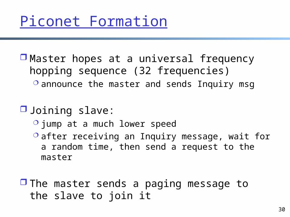
Piconet Formation
Master hopes at a universal frequency hopping sequence (32 frequencies) announce the master and sends Inquiry msg
Joining slave: jump at a much lower speed after receiving an Inquiry message, wait for a
random time, then send a request to the master
The master sends a paging message to the slave to join it
31
Outline
Recap Wireless channels Physical layer design
design for flat fading• how bad is flat fading?• diversity to handle flat fading
– time– space– frequency
» sequential » parallel

32
Direct Sequence Spread Spectrum (DSSS)
Basic idea: increase signaling function alternating rate to expand frequency spectrum (explores frequency in parallel)
fc: carrier freq. Rb: freq. of data10dB = 10; 20dB =100

33
Direct Sequence Spread Spectrum (DSSS)
Approach: One symbol is spread to multiple chips the number of chips is called the expansion factor examples
• 802.11: 11 Mcps; 1 Msps– how may chips per symbol?
• IS-95 CDMA: 1.25 Mcps; 4,800 sps– how may chips per symbol?
• WCDMA: 3.84 Mcps; suppose 7,500 sps – how many chips per symbol?

34
dP/df
f
dP/df
f
sender
Effects of Spreading
un-spread signal
spread signal
BbBbBs Bs
Bs : num. of bits in the chip * Bb

35
DSSS Encoding/Decoding: An Operating View
Xuser data
chippingsequence
modulator
radiocarrier
spreadspectrumsignal
transmitsignal
transmitter
demodulator
receivedsignal
radiocarrier
X
chippingsequence
receiver
low pass
products
decisiondata
sampledsums
correlator

36
DSSS Encoding
user data d(t)
chipping sequence c(t)
resultingsignal
1 -1
-1 1 1 -1 1 -1 1 -11 -1 -1 1 11
X
=
tb
tc
tb: bit periodtc: chip period
-1 1 1 -1 -1 1 -1 11 -1 1 -1 -11

DSSS Encoding
Data: [1 -1 ]
37
chip:
-1 1 1 -1 1 -1
-1 1 1 -1 1 -1
1 -1 -1 1 -1 1

DSSS Decoding
Data: [1 -1]
38
1 -1 -1 1 -1 1
chip:
-1 1 1 -1 1 -1
-1 1 1 -1 1 -1
-1 1 1 -1 1 -1
Transchips
-1 1 1 -1 1 -1Chipseq:
innerproduct: 6
decision: 1
1 -1 -1 1 -1 1-1 1 1 -1 1 -1decodedchips
-6
-1

DSSS Decodingwith noise
Data: [1 -1]
39
1 -1 -1 1 -1 1
chip:
-1 1 1 -1 1 -1
-1 1 1 -1 1 -1
-1 1 1 -1 1 -1
Transchips
-1 1 1 -1 1 -1Chipseq:
innerproduct: 4
decision: 1
1 -1 1 1 -1 -1-1 1 1 -1 -1 -1decodedchips
-2
-1

DSSS Decoding (BPSK): Matched Filter
40
s: modulating sinoid
compute correlationfor each bit time
c: chipping seq.
y: received signaltake N samples ofa bit timesum = 0;for i =0; { sum += y[i] * c[i] * s[i] } if sum >= 0 return 1;else return -1;
bit time
41
Outline
Recap Wireless channels Physical layer design
design for flat fading• how bad is flat fading?• diversity to handle flat fading
– time– space– frequency
» DSSS: why it works?

Assume no DSSS
Consider narrowband interference
Consider BPSK with carrier frequency fc
A “worst-case” scenario data to be sent x(t) = 1 channel fades completely at fc (or a jam
signal at fc) then no data can be recovered
42
43
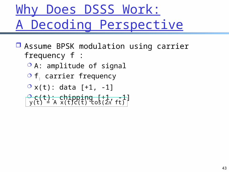
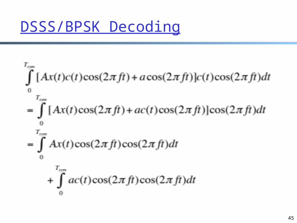
Why Does DSSS Work:A Decoding Perspective Assume BPSK modulation using carrier frequency
f : A: amplitude of signal f: carrier frequency x(t): data [+1, -1] c(t): chipping [+1, -1]
y(t) = A x(t)c(t) cos(2 ft)

44
Add Noise/Jamming/Channel Loss
Assume noise at carrier frequency f:
Received signal: y(t) + w(t)
45
DSSS/BPSK Decoding

46
dP/df
f
i)
dP/df
f
ii)
senderuser signalbroadband interferencenarrowband interference
dP/df
f
iii)
dP/df
f
iv)
receiver
f
v)
dP/df
Why Does DSSS Work:A Spectrum Perspective
i) → ii): multiply data x(t) by chipping sequence c(t) spreads the spectrum ii) → iii): received signal: x(t) c(t) + w(t), where w(t) is noiseiii) → iv): (x(t) c(t) + w(t)) c(t) = x(t) + w(t) c(t)iv) → v) : low pass filtering

Backup Slides

48
Inquiry Hopping

49
The Bluetooth Link Establishment Protocol
FS: Frequency Synchronization
DAC: Device Access Code
IAC: Inquiry Access Code
50
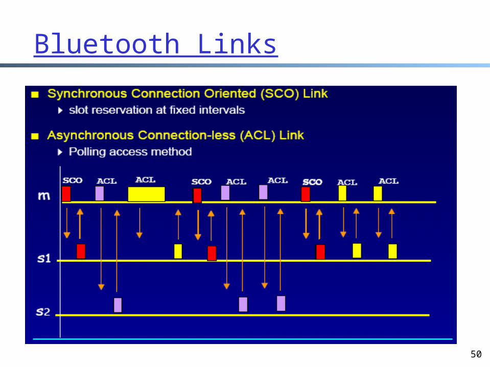
Bluetooth Links

51
Bluetooth Packet Format
Header

52
Multiple-Slot Packet


