Wireless Monitoring System - PM Tech
48
Wireless Monitoring System Models: PowerScant Wireless Monitor GM29535 GM29536 TP-6223 10/05a Operation
Transcript of Wireless Monitoring System - PM Tech

Wireless Monitoring System
Models:
PowerScan Wireless MonitorGM29535GM29536
TP-6223 10/05a
Operation

Product Identification Information
Record the product identification information in the
spaces below immediately after unpacking theproducts
so that the numbers are readily available for future
reference. This information is required to set up and
activate the wireless monitoring service.
Wireless Monitor Information
Record the product identification numbers from the
wireless monitor label.
Model Designation
Device ID Number
Monitored Equipment Information
Record the following information for the equipment
being monitored.
Equipment Name
Address
City
State
Zip Code
Manufacturer
Model
Serial Number
Local Contact Person:
Name
Phone

Table of Contents
TP-6223 10/05 Table of Contents 3
Product Identification Information 2. . . . . . . . . . . . . . . . . . . . . . . . . . . . . . . . . . . . . . . . . . . . . . . . . . . . . . . . . . . .
Safety Precautions and Instructions 5. . . . . . . . . . . . . . . . . . . . . . . . . . . . . . . . . . . . . . . . . . . . . . . . . . . . . . . .
Introduction 7. . . . . . . . . . . . . . . . . . . . . . . . . . . . . . . . . . . . . . . . . . . . . . . . . . . . . . . . . . . . . . . . . . . . . . . . . . . . . . .
Service Assistance 7. . . . . . . . . . . . . . . . . . . . . . . . . . . . . . . . . . . . . . . . . . . . . . . . . . . . . . . . . . . . . . . . . . . . . . . .
Section 1 Features and Specifications 9. . . . . . . . . . . . . . . . . . . . . . . . . . . . . . . . . . . . . . . . . . . . . . . . . . . . . .
1.1 System Description 9. . . . . . . . . . . . . . . . . . . . . . . . . . . . . . . . . . . . . . . . . . . . . . . . . . . .
1.2 Messages 9. . . . . . . . . . . . . . . . . . . . . . . . . . . . . . . . . . . . . . . . . . . . . . . . . . . . . . . . . . . .
1.3 Models 10. . . . . . . . . . . . . . . . . . . . . . . . . . . . . . . . . . . . . . . . . . . . . . . . . . . . . . . . . . . . . .
1.4 Specifications 10. . . . . . . . . . . . . . . . . . . . . . . . . . . . . . . . . . . . . . . . . . . . . . . . . . . . . . . . .
1.5 Indicators and Panel Buttons 11. . . . . . . . . . . . . . . . . . . . . . . . . . . . . . . . . . . . . . . . . . .
1.5.1 LED Indicators 11. . . . . . . . . . . . . . . . . . . . . . . . . . . . . . . . . . . . . . . . . . . . . . . .
1.5.2 Status Lights 11. . . . . . . . . . . . . . . . . . . . . . . . . . . . . . . . . . . . . . . . . . . . . . . . .
1.5.3 Alarm Silence Button 11. . . . . . . . . . . . . . . . . . . . . . . . . . . . . . . . . . . . . . . . . .
1.5.4 Service Button 11. . . . . . . . . . . . . . . . . . . . . . . . . . . . . . . . . . . . . . . . . . . . . . . .
1.6 Battery Pack 11. . . . . . . . . . . . . . . . . . . . . . . . . . . . . . . . . . . . . . . . . . . . . . . . . . . . . . . . . .
1.7 Components and Connections 12. . . . . . . . . . . . . . . . . . . . . . . . . . . . . . . . . . . . . . . . . .
Section 2 Installation 13. . . . . . . . . . . . . . . . . . . . . . . . . . . . . . . . . . . . . . . . . . . . . . . . . . . . . . . . . . . . . . . . . . . . . .
2.1 Introduction 13. . . . . . . . . . . . . . . . . . . . . . . . . . . . . . . . . . . . . . . . . . . . . . . . . . . . . . . . . .
2.2 Required Tools 13. . . . . . . . . . . . . . . . . . . . . . . . . . . . . . . . . . . . . . . . . . . . . . . . . . . . . . . .
2.3 Check Cell Service 13. . . . . . . . . . . . . . . . . . . . . . . . . . . . . . . . . . . . . . . . . . . . . . . . . . . .
2.4 Connect Antenna 13. . . . . . . . . . . . . . . . . . . . . . . . . . . . . . . . . . . . . . . . . . . . . . . . . . . . .
2.5 Check Location 13. . . . . . . . . . . . . . . . . . . . . . . . . . . . . . . . . . . . . . . . . . . . . . . . . . . . . . .
2.6 Check Signal Strength 14. . . . . . . . . . . . . . . . . . . . . . . . . . . . . . . . . . . . . . . . . . . . . . . . .
2.7 Mount Wireless Monitor 14. . . . . . . . . . . . . . . . . . . . . . . . . . . . . . . . . . . . . . . . . . . . . . . .
2.8 Prevent Accidental Starting 14. . . . . . . . . . . . . . . . . . . . . . . . . . . . . . . . . . . . . . . . . . . . .
2.9 Connect Field Wiring 14. . . . . . . . . . . . . . . . . . . . . . . . . . . . . . . . . . . . . . . . . . . . . . . . . .
2.9.1 Hardwire Input Connections 15. . . . . . . . . . . . . . . . . . . . . . . . . . . . . . . . . . . .
2.9.2 Modbus Communication Connections 15. . . . . . . . . . . . . . . . . . . . . . . . . . . .
2.9.3 Remote Start/Stop Connections 15. . . . . . . . . . . . . . . . . . . . . . . . . . . . . . . . .
2.10 Set DIP Switches 15. . . . . . . . . . . . . . . . . . . . . . . . . . . . . . . . . . . . . . . . . . . . . . . . . . . . .
2.11 Connect Monitor Power 16. . . . . . . . . . . . . . . . . . . . . . . . . . . . . . . . . . . . . . . . . . . . . . . .
2.11.1 AC-Powered Installations 16. . . . . . . . . . . . . . . . . . . . . . . . . . . . . . . . . . . . . . .
2.11.2 DC-Powered Installations 16. . . . . . . . . . . . . . . . . . . . . . . . . . . . . . . . . . . . . . .
2.12 Record Important Information 16. . . . . . . . . . . . . . . . . . . . . . . . . . . . . . . . . . . . . . . . . . .
2.13 Connect Equipment Power 17. . . . . . . . . . . . . . . . . . . . . . . . . . . . . . . . . . . . . . . . . . . . .
2.14 Set Up an Account 17. . . . . . . . . . . . . . . . . . . . . . . . . . . . . . . . . . . . . . . . . . . . . . . . . . . .
2.15 Test Monitor 17. . . . . . . . . . . . . . . . . . . . . . . . . . . . . . . . . . . . . . . . . . . . . . . . . . . . . . . . . .
Section 3 Account Setup 19. . . . . . . . . . . . . . . . . . . . . . . . . . . . . . . . . . . . . . . . . . . . . . . . . . . . . . . . . . . . . . . . . .
3.1 Account Setup 19. . . . . . . . . . . . . . . . . . . . . . . . . . . . . . . . . . . . . . . . . . . . . . . . . . . . . . . .
3.1.1 Access the Website 19. . . . . . . . . . . . . . . . . . . . . . . . . . . . . . . . . . . . . . . . . . .
3.1.2 Set up the Account 20. . . . . . . . . . . . . . . . . . . . . . . . . . . . . . . . . . . . . . . . . . . .
3.1.3 Obtain a Member ID Number 20. . . . . . . . . . . . . . . . . . . . . . . . . . . . . . . . . . . .
3.1.4 Log On to Your Account 20. . . . . . . . . . . . . . . . . . . . . . . . . . . . . . . . . . . . . . . .
3.2 Device Activation 22. . . . . . . . . . . . . . . . . . . . . . . . . . . . . . . . . . . . . . . . . . . . . . . . . . . . . .

Table of Contents, continued
TP-6223 10/05Table of Contents4
Section 4 Device Messaging Configuration 25. . . . . . . . . . . . . . . . . . . . . . . . . . . . . . . . . . . . . . . . . . . . . . . . .
4.1 Web Page Access 25. . . . . . . . . . . . . . . . . . . . . . . . . . . . . . . . . . . . . . . . . . . . . . . . . . . . .
4.2 Logging In 25. . . . . . . . . . . . . . . . . . . . . . . . . . . . . . . . . . . . . . . . . . . . . . . . . . . . . . . . . . . .
4.3 Menus and Submenus 26. . . . . . . . . . . . . . . . . . . . . . . . . . . . . . . . . . . . . . . . . . . . . . . . .
4.4 View and Edit Devices Screen (View All Devices and Select a Single Device) 27.
4.5 Install New Device Screen 28. . . . . . . . . . . . . . . . . . . . . . . . . . . . . . . . . . . . . . . . . . . . . .
4.6 User Information Screen (Website Manager) 29. . . . . . . . . . . . . . . . . . . . . . . . . . . . . .
4.7 Credit References Screen 30. . . . . . . . . . . . . . . . . . . . . . . . . . . . . . . . . . . . . . . . . . . . . .
4.8 Device Info Screen (Selecting the Device Contact and Configuring Equipment) 30
4.8.1 Control Panel 33. . . . . . . . . . . . . . . . . . . . . . . . . . . . . . . . . . . . . . . . . . . . . . . . .
4.8.2 Remote Start/Stop 35. . . . . . . . . . . . . . . . . . . . . . . . . . . . . . . . . . . . . . . . . . . . .
4.9 Last Message Summary Screen (Alarm History for all Website Devices) 36. . . . . .
4.10 Manage All Deliveries Screen (Assign and Revise Message Delivery) 37. . . . . . . .
4.11 Message Delivery Screen (Selecting Messages for Device Inputs) 38. . . . . . . . . . .
4.12 Message History Screen (Reviewing Message History for Single Inputs) 40. . . . . .
4.13 Heartbeat History Screen 41. . . . . . . . . . . . . . . . . . . . . . . . . . . . . . . . . . . . . . . . . . . . . . .
4.14 Assign Users Screen (User Rights) 42. . . . . . . . . . . . . . . . . . . . . . . . . . . . . . . . . . . . . .
Appendix A Abbreviations 43. . . . . . . . . . . . . . . . . . . . . . . . . . . . . . . . . . . . . . . . . . . . . . . . . . . . . . . . . . . . . . . . . .
Appendix B Noise and Wiring Practices 45. . . . . . . . . . . . . . . . . . . . . . . . . . . . . . . . . . . . . . . . . . . . . . . . . . . . . .

TP-6223 10/05 5Safety Precautions and Instructions
Safety Precautions and Instructions
IMPORTANT SAFETY INSTRUCTIONS.
Electromechanical equipment,including generator sets andaccessories, can cause bodily harm
and pose life-threatening danger whenimproperly installed, operated, ormaintained. To prevent accidents beaware of potential dangers and actsafely. Read and follow all safetyprecautions and instructions. SAVE
THESE INSTRUCTIONS.
Thismanual hasseveral typesofsafetyprecautions and instructions: Danger,Warning, Caution, and Notice.
DANGER
Danger indicates the presence of ahazard that will cause severe
personal injury,death, orsubstantialproperty damage.
WARNING
Warning indicates the presence of ahazard that can cause severe
personal injury,death,orsubstantial
property damage.
CAUTION
Caution indicates the presence of a
hazard that will or can cause minor
personal injury or property damage.
NOTICE
Notice communicates installation,operation, or maintenance informationthat is safety related but not hazardrelated.
Safety decals affixed to the equipmentin prominent places alert the operatoror service technician to potentialhazards and explain how to act safely.
The decals are shown throughout thispublication to improve operatorrecognition. Replace missing ordamaged decals.
Hazardous Voltage/Electrical Shock
Hazardous voltage.
Will cause severe injury or death.
Disconnect all power sources before
servicing. Install the barrier after
adjustments, maintenance, or
servicing.
DANGER

TP-6223 10/056 Safety Precautions and Instructions
Notes

TP-6223 10/05 7Introduction
Introduction
This manual provides installation, setup, and operation
instructions for the Kohler PowerScan wireless
monitoring system. This device must be installed in
accordance with the National Electrical Code
(NFPA 70), local codes, and the authorities having
jurisdiction.
Information in this publication represents data available
at the time of print. Kohler Co. reserves the right to
change this literature and the products represented
without notice and without any obligation or liability
whatsoever.
Read this manual and carefully follow all procedures
and safety precautions to ensure proper equipment
operation and to avoid bodily injury. Read and follow the
Safety Precautions and Instructions section at the
beginning of this manual. Keep this manual with the
equipment for future reference.
Service Assistance
For wireless monitor device activation in the US and
Canada, visit the Kohler Power Systems website at
KohlerPowerSystems.com.
For professional advice on generator power
requirements and conscientious service, please contact
your nearest Kohler distributor or dealer.
Consult the Yellow Pages under the heading
Generators—Electric
Visit the Kohler Power Systems website at
KohlerPowerSystems.com
Look at the labels and stickers on your Kohler product
or review the appropriate literature or documents
included with the product
Call toll free in the US and Canada 1-800-544-2444

TP-6223 10/058 Service Assistance
Notes

TP-6223 10/05 9Section 1 Features and Specifications
Section 1 Features and Specifications
1.1 System Description
The wireless monitor system has two components: a
wireless monitor device, shown in Figure 1-1, and a
messaging center with a website. The monitor device
transmitsmessages in response to inputs received from
the equipment controller. The messaging center
monitors and delivers these messages to the assigned
recipients through selected delivery methods.
Figure 1-1 Wireless Monitor
The user logs on to the messaging center website to
activate each wireless monitor, assign recipients for
each message type and the delivery method for each
recipient, review the status and message history for
each device, and start or stop the equipment remotely, if
desired.
Note: Disconnect power to connected equipment
before servicing or maintenance to prevent
starting of the equipment by a remote device.
Refer to the equipment manufacturer’s
instructions.
If a monitoring device is removed from service, log onto
the messaging center website to deactivate the device.
Devices not deactivated will continue to be billed. See
Section 4.4 for instructions to deactivate a device.
1.2 Messages
At the website, the user assigns recipients for each
message type and the delivery method for each
recipient. Single or multiple messages regarding
various operating conditions can be sent to each
recipient. Delivery methods include pagers
(alphanumeric, numeric), fax, XML, e-mail, PCS, or
telephone (voice delivery). More than one delivery
method can be selected for each recipient. Each
message sent will describe the condition that generated
the transmission and also themake,model, and location
of the equipment. Up to 40 messages each day can be
delivered.
The wireless monitor constantly monitors the inputs.
When an input is triggered, the wireless monitor sends
the condition over theNorth American AMPS (advanced
mobile phone system). An operations center server
receives the transmission and forwards the message to
the selected recipients according to the configured
delivery method.
Every 24 hours, the wireless monitor sends information
about itself and the system it is monitoring. This
heartbeat transmission tells themessage center that the
wireless monitor is properly functioning, powered, and
able to generate messages. If a device fails to report a
nightly heartbeat for more than a day, the system sends
a Unit Failed to Report Heartbeat alarm message to the
website.
Equipment run times are reported daily. Models using
hardwire inputs accumulate run times over a 24-hour
period and report the run times with the heartbeat
message. Models using Modbus communication
report the total accumulated run time and the total
number of starts with the heartbeat message. Run
times for thesemodels are also totaled using theControl
Panel function and can be updated upon request.
Modbus is a registered trademark of Schneider Electric
TP-6223 10/0510 Section 1 Features and Specifications
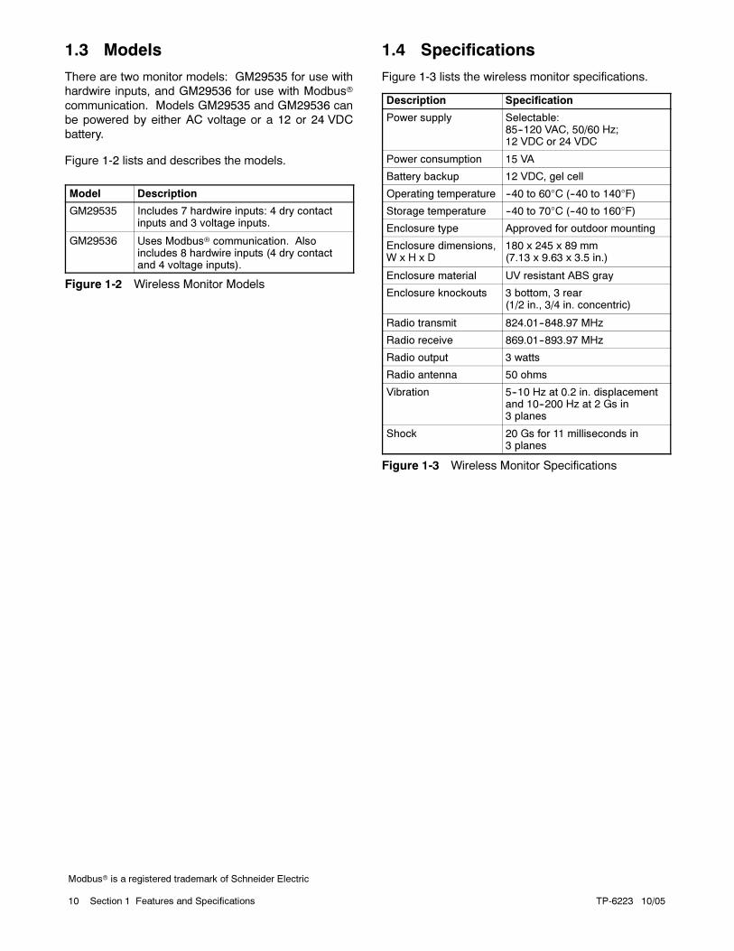
1.3 Models
There are two monitor models: GM29535 for use with
hardwire inputs, and GM29536 for use with Modbus
communication. Models GM29535 and GM29536 can
be powered by either AC voltage or a 12 or 24 VDC
battery.
Figure 1-2 lists and describes the models.
Model Description
GM29535 Includes 7 hardwire inputs: 4 dry contactinputs and 3 voltage inputs.
GM29536 Uses Modbus communication. Alsoincludes 8 hardwire inputs (4 dry contactand 4 voltage inputs).
Figure 1-2 Wireless Monitor Models
1.4 Specifications
Figure 1-3 lists the wireless monitor specifications.
Description Specification
Power supply Selectable:85--120 VAC, 50/60 Hz;12 VDC or 24 VDC
Power consumption 15 VA
Battery backup 12 VDC, gel cell
Operating temperature --40 to 60°C (--40 to 140°F)
Storage temperature --40 to 70°C (--40 to 160°F)
Enclosure type Approved for outdoor mounting
Enclosure dimensions,W x H x D
180 x 245 x 89 mm(7.13 x 9.63 x 3.5 in.)
Enclosure material UV resistant ABS gray
Enclosure knockouts 3 bottom, 3 rear(1/2 in., 3/4 in. concentric)
Radio transmit 824.01--848.97 MHz
Radio receive 869.01--893.97 MHz
Radio output 3 watts
Radio antenna 50 ohms
Vibration 5--10 Hz at 0.2 in. displacementand 10--200 Hz at 2 Gs in3 planes
Shock 20 Gs for 11 milliseconds in3 planes
Figure 1-3 Wireless Monitor Specifications
Modbus is a registered trademark of Schneider Electric

TP-6223 10/05 11Section 1 Features and Specifications
1.5 Indicators and Panel Buttons
Figure 1-5 shows the wireless monitor with the cover
removed to show the components described in the
following sections. Refer to Section 2, Installation, for
information about DIP switches and other components
not listed below.
1.5.1 LED Indicators
The red LED above each input illuminates when the
input is on. The LEDs are not visible when the cover
panel is in place.
The numerical LED displays the following codes:
0--9 to indicate the cell signal strength during normal
operation
F when the device is in service mode
A decimal point ( . ) if the power has been
disconnected
A code (— 1 —) to indicate Modbus communication
when the alarm silence button is pressed three times;
see Section 1.5.3 (Modbus models only).
1.5.2 Status Lights
The yellow status light flashes once per second during
normal operation to indicate that the wireless monitor
registers service, is available, and is ready to send. See
Figure 1-4. The yellow light flashes rapidly when the
device is holding a message.
The green status light flashes several times and then
flashes quickly for approximately 2 seconds when the
monitor sends a message to the message center. If
green light flashes only twice, themessage did not leave
the device. The device will hold the message and retry
every 10--15 seconds.
Status Light
Yellow Green Indicates
Off Off Service not available
Flashingonce/sec. Off
Service available,ready to transmit
Flashingrapidly Off Holding message
On Flashes once or twice Transmitting message
OnFlashes rapidly for2 sec.
Successfultransmission
Figure 1-4 Status Lights
1.5.3 Alarm Silence Button
The alarm silence button silences the audible alarm on
the monitor device. The audible alarm occurs when the
equipment controller signals a fault/alarm. Select fault
assignments on the website (See Section 4). The alarm
sounds again five minutes after the button is pressed if
the fault is not corrected. The audible alarm can be
disabled by a DIP switch selection. The audible alarm is
not available for any alarms received via Modbus
connection.
On models equipped with Modbus communication,
press the alarm silence button three times to to check for
successful communication. The LED will display the
sequence dash one dash (— 1 —) to indicate that the
monitor is communicating with the equipment controller.
A series of dashes without a number (———) indicates
a loss of communication with the equipment controller.
1.5.4 Service Button
Pressing the service button sends a message to the
website that a technician has arrived on-site. An F on
the monitor LED display indicates the service mode.
The web screen displays Service Button. To minimize
nuisance alarmmessages, the monitor does not accept
alarms from the equipment during servicing.
The technicianmust press the service button again after
service to reset the monitor to receive alarms. The
monitor automatically resets 120 minutes after the
service button is pressed. A signal strength number
(0--9) on the monitor LED display indicates that the
device has returned to normal operation.
1.6 Battery Pack
A rechargeable battery supplies power to AC-powered
devices if AC power is lost. The monitor continues to
transmit messages for 15minutes, then transmits a loss
of power signal and enters the sleep mode. The sleep
mode can last up to 18 hours, until the battery
completely discharges or power is restored. The
wirelessmonitor continues to send scheduled heartbeat
messages during the sleep mode until the battery
discharges completely. The sleep mode is disabled if
the DC power mode is selected (DIP switch 4).
For DC-powered monitor devices, the rechargeable
battery pack can be used during the location and signal
strength checks in Section 2. Do not use the
rechargeable battery pack as a permanent power
source for the monitor.
Modbus is a registered trademark of Schneider Electric

TP-6223 10/0512 Section 1 Features and Specifications
1.7 Components and Connections
1. Antenna connection
2. Radio module3. Antenna cable connection
4. Processor module (internal)
5. Option button (alarm silence)6. Service button
7. Status lights
8. Input indication lights
9. Fuse, 1 amp, 250 volt, fast blow, 3 AG *10. AC Power supply 23, 24 (85--120 VAC, 60 Hz)
11. Use this knockout for Class I leads
12. Device wiring 22 (earth ground)13. Voltage inputs 13-20 (24--120 VAC or 5--48 VDC)
14. Terminal blocks (use 12--18 AWG for connections)
15. Dry contact inputs 5-12 (do not apply voltage)16. Relay inputs 3, 4 (not used)
17. Relay inputs 1, 2 start/stop relay
18. Use this knockout for Class II leads
19. DC power supply connection (12 or 24 VDC)
20. Battery pack connector (not connected in DC-powered
installations)
21. Signal strength (LED) indicator (0--9=signal strength,F=service mode)
22. Modbus RS-485 RJ11 communication ports or factory test
ports23. DIP switches; see Section 2.10
* A blown fuse usually indicates a problem that needs to be corrected. Do not replace the fuse withoutidentifying and correcting the problem.
Never mix Class I and Class II leads. Install signal leads and AC or DC power conductors in separate raceways, cables, or conduit.Always follow the National Electrical Code (NEC) and applicable local codes.
41 2
5
6
7
8
9*
1013
21
20
22 23
1517 1416
3
19
1118
+
--
12
Figure 1-5 Wireless Monitor Components and Connections (shown with cover removed)
Modbus is a registered trademark of Schneider Electric

TP-6223 10/05 13Section 2 Installation
Section 2 Installation
2.1 Introduction
This section covers the installation and test of the
wireless monitor. Install this device in accordance with
the National Electrical Code (NFPA 70), local codes,
and the authorities having jurisdiction. Perform the test
after the installation, account setup, and message
configuration are complete.
Sections 3 and 4 explain account setup and message
configuration, which must be done on the Internet at the
Kohler website (KohlerPowerSystems.com). Either
configure the wireless monitor by completing the
account setup and message configuration before
installation (installation details can be filled in later) or
arrange to have someone available at the equipment
site to help test the monitor after completing the Internet
setup.
2.2 Required Tools
One wireless monitor device
One 85--120 VAC or 12/24 VDC power supply
Watertight fittings to seal enclosure penetrations
Screws to surface-mount the enclosure
Screwdriver, wire for power supply connection, and
12--18 AWG wire for input connections
2.3 Check Cell Service
There are some regions where cell coverage is
available but Kohler service is not. A coverage map is
available at the website, KohlerPowerSystems.com,
under Coverage Maps (see Figure 3-3). Simply enter
the zip code where you wish to install the wireless
monitor to see if monitoring service is available.
2.4 Connect Antenna
The antenna connections on the enclosure are factory-
installed to prevent water from entering the enclosure.
DO NOT change any of these existing connections.
Simply screw the antenna to the connector on the top of
the wireless monitor enclosure. See Figure 1-5 for the
connector location.
2.5 Check Location
Take the wireless monitor to the area where the
equipment to be monitored is located. The wireless
monitor can be located either indoors or outside. Mount
the wireless monitor in a location where the ambient
temperature range does not exceed --40 C to 60 C
(--40 F to 140 F).
Locate the wireless monitor no more than 12 m (40 ft.)
from the monitored equipment but at least 0.8 m (2.5 ft.)
from electronic components to avoid signal
interference. Check locations where the antenna rises
at least 50 mm (2 in.) above or is directed away from the
equipment. Avoid mounting the monitor on vibrating
equipment.
The wireless monitor will be able to send messages in
locations where analog cell phones will work. If the
equipment is in an area where an analog cell phone
cannot get a signal, it is likely the wireless monitor will
not be able to get a signal either.
Startup and Signal Check Procedure
1. Plug the battery pack into the battery pack
connector provided on the monitor. See
Figure 1-5, item 20.
2. The wireless monitor will begin a startup routine.
The startup time will vary but may last up to several
minutes as the wireless monitor establishes a
connection to a cell site and registers a message.
3. During the startup routines, the Signal Strength
Indicator display segments will rotate. Initially, the
middle display segment will not be lit. When the
middle segment comes on, the wireless monitor
has successfully completed the first half of the
startup routines.
4. Check the yellow status light. The yellow status
light (see Figure 1-4) flashes once per second and
the signal strength is displayed when service is
available. See Section 2.6, Cell Coverage Check.

TP-6223 10/0514 Section 2 Installation
5. Walk around the equipment or the equipment room
with the wireless monitor powered by the battery
pack.
Note: On battery power, the monitor will display the
signal strength for 15minutes before it goes into a
sleep mode and displays a decimal point. Simply
unplug the battery pack and then reconnect to
continue on battery power to determine final
location.
6. Place the wireless monitor in several sample
mounting locations and check the signal strength
by observing the signal strength indicator. Check
locations where the antenna rises at least 50 mm
(2 in.) above or is directed away from the
equipment. The cell signal strength can range from
0 to 9. The higher the signal strength number, the
better the signal. See Section 2.6, Check Signal
Strength.
Note: A signal strength less than 2 will not provide
reliable message transmission. A high-gain
antenna may be required.
7. When the mounting location with the strongest
(highest number) signal strength is found,
disconnect the battery pack connection until the
final installation has been completed.
Nuisance alarms are sometimes triggered when the
equipment is being tested or serviced. To avoid
nuisance alarms, do not connect the power supply or
reconnect the battery to the wireless monitor until
instructed to do so in Section 2.11.
2.6 Check Signal Strength
After the initial startup routine, the LED numerical
display shows the cell signal strength at the wireless
monitor location. The cell signal strength can range
from 0 to 9. The higher the signal strength number, the
better the signal.
The wireless monitor sends out a sample message and
then waits for a return signal to determine if Kohler
service is available at this site. The yellow status light
(see Figure 1-4) will flash once a second and the signal
strength will be displayed when service is available.
Telemetry system delays may occur in cell coverage
areas due to high traffic volume that may result in
message delays.
A signal strength less than 2 will not provide reliable
message transmission. A high-gain antenna may be
required.
2.7 Mount Wireless Monitor
Choose a surface that is flat and strong enough to hold
the wireless monitor. Avoid mounting the device on
vibrating equipment. Locate the wireless monitor no
more than 12 m (40 ft.) from the monitored equipment
but at least 0.8 m (2.5 ft.) from electronic components to
avoid signal interference. The antenna must clear the
top of the equipment by 50 mm (2 in.) minimum.
The enclosure has one keyhole mounting tab extending
from the top of it and two mounting tabs extending
underneath. Use all three tabs to secure the device.
Note: This enclosure is UL approved for outdoor use.
DO NOT drill any holes into or through the
enclosure. Use watertight fittings in the precast
holes at the bottom of the enclosure for wire
entrances.
2.8 Prevent Accidental Starting
Before proceeding to wire the power supply and input
connections, disconnect power to the monitored
equipment to prevent accidental starting. Refer to the
equipment manufacturer’s documentation for
instructions.
2.9 Connect Field Wiring
Open themonitor enclosure and remove the four screws
securing the black panel cover to gain access to the
input terminals and LEDs (see Figure 1-5).
The enclosure is equipped with six knockouts. DONOT
make any other holes in the enclosure. Bring all Class 1
and Class 2 wiring into the enclosure through separate
knockouts. See NFPA 70, National Electric Code,
Article 725 for definitions of Class 1 and Class 2 circuits.
Install signal leads and AC or DC power conductors in
separate raceways, cables, or conduit.
After removing a knockout, seal it with a watertight fitting
(not supplied) if the wireless monitor is being mounted
outdoors.
Note: Watertight fittings at the knockout openings are
required in order to maintain the enclosure’s UL
outdoor approved rating.
Route all field wiring away from sharp projections,
corners, and internal components.
Refer to the equipment manufacturer’s wiring diagrams
for connection diagrams.

TP-6223 10/05 15Section 2 Installation
2.9.1 Hardwire Input Connections
Each wireless monitor model has different functions for
the four sets of dry contact inputs and the four sets of
voltage inputs (see Figure 1-5).
Select up to four available dry contact outputs and up to
four DC voltage outputs to connect to the wireless
monitor. Use 12--18 AWG wire for field connections to
the wireless monitor inputs. Refer to the equipment
manufacturer’s wiring diagrams to connect the
equipment outputs to the wireless monitor input
terminals. Note the polarity of the connections and the
maximum voltage indicated in Figure 1-5. Follow the
equipment wiring diagrams carefully.
Note: Reversed polarity causes a fault.
Set DIP switch 3 for the dry contact inputs as shown in
Figure 2-1.
2.9.2 Modbus Communication
Connections
Model GM29536 supports Modbus network
communications. A 14 ft. communication cable is
supplied with these models. Connect the RJ11
connector to the Modbus port on the monitor device.
Refer to the equipment manufacturer’s instructions to
wire the other end of the communication cable to the
Modbus communication terminal on the connected
equipment.
The monitor device communicates at 9600 baud. Refer
to the manufacturer’s instructions to set the connected
equipment to communicate at 9600 baud.
2.9.3 Remote Start/Stop Connections
To allow remote starting and stopping of the monitored
equipment through the message center website,
connect the equipment’s remote start/stop circuit to
monitor terminals 1 and 2. The monitor’s remote
start/stop DIP switch must also be enabled for remote
starting and stopping; see Section 2.10.
Note: Disable monitored equipment during
maintenance or service to prevent accidental
starting. See the equipmentOperation or Service
Manual for instructions.
2.10 Set DIP Switches
The four DIP switches on the wireless monitor are
assigned to the functions shown in Figure 2-1. Set the
DIP switches to the appropriate positions for the
application. DIP switch positions with the monitor
oriented as shown in Figure 1-5 are: up = on, down = off.
Note: The wireless monitor is shipped with all DIP
switches in the down (off) position.
DIP
Switch Models Function Notes *
1 All Remote start/stopenable/disable
Set in conjunction with relay input terminals 1 and 2 for remote start/stopoperation.On = Enable remote start/stop
Off = Disable remote start/stop
2 All Audible alarmenable/disable
Audible alarm can also be silenced by pushbutton.On = Enable audible alarmOff = Disable audible alarm
3 GM29535 Input 4 active oncontact open orclosed
Applies to dry contact input #4 only.On = Active on openOff = Active on closed
GM29536 Inputs 1--4 active oncontact open orclosed
Applies to all dry contact inputs.On = Active on openOff = Active on closed
4 GM29535GM29536
AC/DC powersupply selection
On = DC power supplyOff = AC power supply
* DIP switch positions: on = up, off = down. The wireless monitor is shipped with all DIP switches in the down (off) position.
Disable monitored equipment during maintenance or service to prevent accidental starting.
Figure 2-1 DIP Switches

TP-6223 10/0516 Section 2 Installation
2.11 Connect Monitor Power
Hazardous voltage.
Will cause severe injury or death.
Disconnect all power sources before
servicing. Install the barrier after
adjustments, maintenance, or
servicing.
DANGER
Wireless monitor models GM29535 and GM29536
operate with either AC (85--120 VAC, 50/60 Hz) or DC
(12 or 24 VDC) power.
Note: The battery pack mounted inside the monitor
enclosure does not function as a permanent DC
power supply for the device. The battery pack is
intended for temporary power during equipment
setup or AC power loss and connects to a
different connector than the DC power supply.
2.11.1 AC-Powered Installations
Refer to Figure 1-5. Connect themonitor device battery
pack before wiring main power. The battery pack
connection is on the left side of the monitor.
For AC-powered installations, provide an AC power
supply with a voltage within the range 85--120 VAC.
Provide a stepdown transformer for power supply
voltages over 120 VAC. Connect the monitor to a
receptacle or circuit that is powered by backup power so
that the monitor continues to function if the utility power
fails. Connect the AC power supply to terminals 22 -- 24
(see Figure 1-5).
2.11.2 DC-Powered Installations
Models GM29535 and GM29536 can be powered by 12
or 24 VDC fromabattery or otherDC power supply. Use
a battery charger to maintain the battery.
For battery-powered (DC) installations, do not connect
the battery pack mounted inside the monitor enclosure.
Move DIP switch 4 to the DC position (DIP switch in the
ON [up] position). See Figure 2-1. Connect the external
battery harness (provided) to the battery. See
Figure 1-5 for connections. Then plug the harness
connector into the battery connection on the wireless
monitor.
The monitor does not enter the sleep mode when
battery-powered with DIP switch 4 in the DC position.
Fuse. The battery harness contains a 5-amp, 250-volt
fast-acting ceramic fuse, Kohler part number 233298. If
the fuse blows, determine and correct the cause of the
blown fuse. Replace a blown fuse with an identical part.
2.12 Record Important Information
Record the following information to use for account
setup and message configuration.
TheDevice ID number, located on the label inside the
monitor. See Figure 2-2 for the location of the Device
ID number on the label.
Note: DO NOT leave the site without recording the
Device ID number. Without this number, the
device cannot be configured at the website.
The location name for the piece of equipment being
monitored, and the exact street address, city, state,
and zip code where the wireless monitor is located.
The local contact phone and name. These should be
the phone number and name of the person(s) who
would need to be contacted in order to gain access to
this wireless monitor.
The equipment name for the piece of equipment
being monitored. Try to be as specific as possible,
especially if there are multiple pieces of equipment
that will have wireless monitors installed at a single
site.
The equipment manufacturer, model, and serial
number. This information should be sufficient to
identify repair or replacement parts before a service
person is dispatched to the site.
Figure 2-2 Label with Device ID in Upper Right
Corner

TP-6223 10/05 17Section 2 Installation
2.13 Connect Equipment Power
Refer to the equipment manufacturer’s instructions to
reconnect power to the equipment and return it to
normal operation.
2.14 Set Up an Account
Use the information collected in Section 2.12 to set up
an account. Connect to the Internet and access
www.KohlerPowerSystems.com. The steps to set up a
Kohler account are explained in Section 3.
2.15 Test Monitor
Perform the test in this section after configuring the
wireless monitor at the Kohler website as instructed in
Sections 3 and 4. Testing requires a person at the
equipment site and someone with access to the web
page.
Note that while the following test is recommended, a
properly functioning wireless monitor will send out a
Heartbeat message every night. Therefore, it is
possible to check the system operation by simply
waiting until the next morning and then checking the
website to determine if the wireless monitor sent out a
message.
Equipment Site Test Procedure
1. Verify that the yellow status light is flashing once
per second (see Figure 1-4). This indicates the
wirelessmonitor registers service, is available, and
is ready to send. The green status light should be
off.
2. Press and release the Service Button. The yellow
light flashes rapidly to indicate that it is waiting to
send a message. The green light flashes several
times and then flashes quickly for approximately 2
seconds to indicate that the message has been
sent.
Note: If green light flashes only twice, the
message did not leave the monitor. The
monitor will hold the message and retry
every 10--15 seconds.
3. After the message has been successfully sent,
check that the green light turns off and the yellow
light flashes every second, showing that the
wireless monitor is ready to send another
message.
Cell tower traffic can cause occasional delays in
message transmission. If the message does not go
through after the first few attempts, the yellow light
flashes rapidly to indicate that the monitor is holding a
message. After about 5 minutes, the monitor will
attempt to transmit the message again. The yellow light
will light steadily and the green light will again begin to
flash, indicating an attempt to transmit. This cycle will
continue until the message is sent.
Website Test Procedure
1. Access the Kohler website and log in to the
PowerScan site. SeeSection 4 for instructions to
log onto and navigate the website.
2. Confirm that the equipment information is correct
including the name, model, make, and address.
Confirm the contact information is correct. The
correct information is the name and telephone
number of the individual(s) who can provide
access to the equipment.
3. Verify that the Device Information screen shows
the message that the service button has been
pressed.
4. Check that all the other appropriate messages
were received. Make sure the appropriate
individuals were paged, that the appropriate faxes
were sent, and the appropriate telephone calls
were made.

TP-6223 10/0518 Section 2 Installation
Notes

TP-6223 10/05 19Section 3 Account Setup
Section 3 Account Setup
A Kohler account is required to configure the wireless
monitor. The account will contain billing information for
thewirelessmonitor service. Use the Internet to set up a
Kohler account and configure the wireless monitor.
The following sections explain how to set up an account.
You must provide your Kohler customer number to set
up and access your account. Select a password for
website access. Once you complete and submit the
billing information and password, you will receive a
member ID. Use your member ID and password to set
up and access devices on a password-secure website.
The member ID determines the address used for
invoicing.
Important: Record your member ID and password
and place them in a safe location. You will need this
information each time you access your account.
If you already have amember ID and password, skip this
section and proceed to Section 4.
3.1 Account Setup
3.1.1 Access the Website
To set up an account, connect to the Internet and go to
the Kohler web page at KohlerPowerSystems.com.
Click on On-Site Power Systems on the Kohler Power
Systems home page. TheOn-Site Power systemspage
is shown in Figure 3-2. Click on Wireless Monitoring to
access the login screen shown in Figure 3-3. SelectSet
Up A PowerScan Account.
The login screen also contains a link to the coverage
map. Click on the Coverage Map link to check cell
phone coverage in your area, if desired.
Figure 3-1 KohlerPowerSystems.com Home Page
1. Click on Wireless Monitoring to access the wireless monitor
service website.
1
Figure 3-2 KohlerPowerSystems.com On-Site
Power Systems Page
TP-6223 10/0520 Section 3 Account Setup
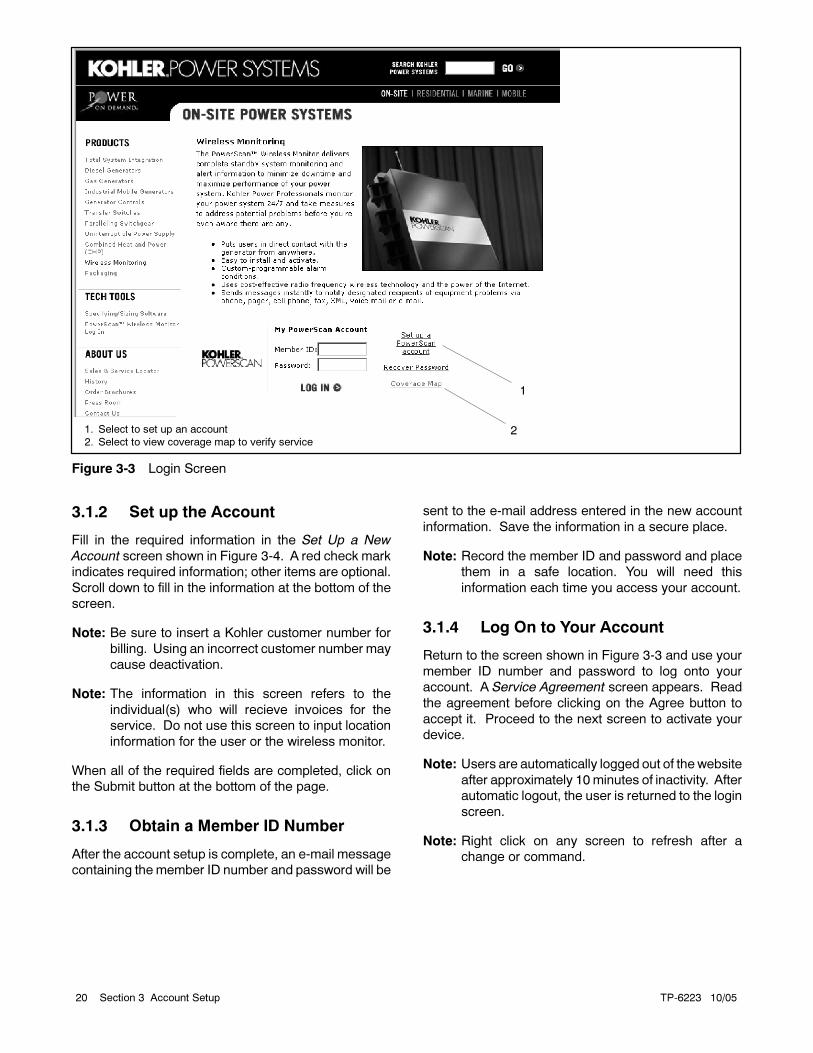
1. Select to set up an account
2. Select to view coverage map to verify service
1
2
Figure 3-3 Login Screen
3.1.2 Set up the Account
Fill in the required information in the Set Up a New
Account screen shown in Figure 3-4. A red check mark
indicates required information; other items are optional.
Scroll down to fill in the information at the bottom of the
screen.
Note: Be sure to insert a Kohler customer number for
billing. Using an incorrect customer number may
cause deactivation.
Note: The information in this screen refers to the
individual(s) who will recieve invoices for the
service. Do not use this screen to input location
information for the user or the wireless monitor.
When all of the required fields are completed, click on
the Submit button at the bottom of the page.
3.1.3 Obtain a Member ID Number
After the account setup is complete, an e-mail message
containing the member ID number and password will be
sent to the e-mail address entered in the new account
information. Save the information in a secure place.
Note: Record the member ID and password and place
them in a safe location. You will need this
information each time you access your account.
3.1.4 Log On to Your Account
Return to the screen shown in Figure 3-3 and use your
member ID number and password to log onto your
account. A Service Agreement screen appears. Read
the agreement before clicking on the Agree button to
accept it. Proceed to the next screen to activate your
device.
Note: Users are automatically logged out of thewebsite
after approximately 10 minutes of inactivity. After
automatic logout, the user is returned to the login
screen.
Note: Right click on any screen to refresh after a
change or command.

TP-6223 10/05 21Section 3 Account Setup
XXXXX
Your Company Name
John
Q.
Smith
123 Main Street
Anytown
Wisconsin
12345
888 555--1234
********
********
Note: Be sure to insert a Kohler account number for billing purposes.
Kohler invoices the distributor for device services. Using anincorrect customer number may cause deactivation.
Figure 3-4 Set Up a New Account

TP-6223 10/0522 Section 3 Account Setup
3.2 Device Activation
Multiple devices can be installed on a single account.
Select the Install New Device tab near the top of the
screen to begin device setup. See Figure 3-5. Enter the
numericDevice ID, shown on the label inside the device.
See Section 2.12 for the Device ID number location on
the label. Click on the submit button to activate the
device at the operations center.
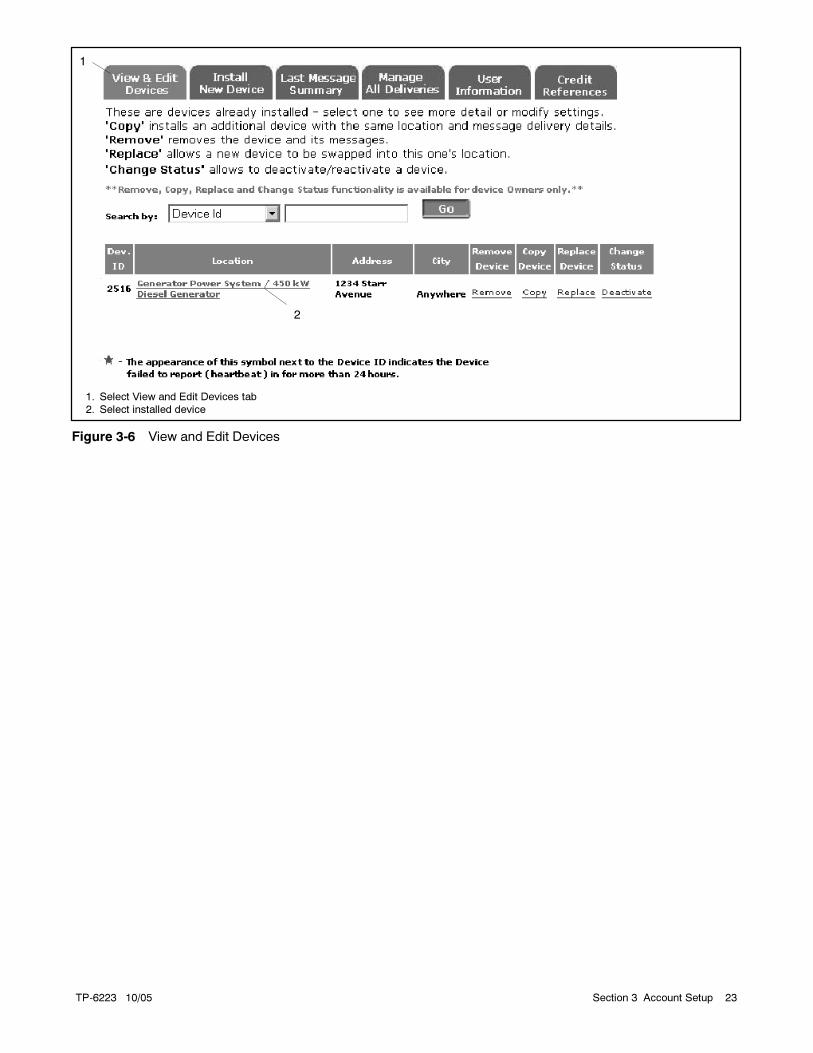
After submitting the Device ID, select the View and Edit
Devices tab. See Figure 3-6. Installed devices are
listed on the screen. Select the installed device by
clicking on the underlined description in the Location
column. The Device Information screen shown in
Figure 3-7 appears.
Complete and submit the Device Information screen to
finish the activation. Scroll down to see all of the
required fields. The information in this screen refers to
the equipment location.
Note: Voice messages include the alarm type,
equipment name, location, address, make, and
model. Enter concise information into the
equipment name, make, and model fields or
leave some of those fields blank for short,
concise voice messages.
Proceed to Section 4 for instuctions to set up the
message delivery for each device.
1. Select Install New Device tab
2. Enter the device ID number from the wireless monitor label
2
1
Figure 3-5 Install New Device
TP-6223 10/05 23Section 3 Account Setup
1. Select View and Edit Devices tab
2. Select installed device
1
2
Figure 3-6 View and Edit Devices

TP-6223 10/0524 Section 3 Account Setup
GM23409-KP2S
9999
Figure 3-7 Device Information Screen
TP-6223 10/05 25Section 4 Device Messaging Configuration
Section 4 Device Messaging Configuration
If you have a Kohler PowerScan member ID and
password, proceed with the steps below to configure
wireless monitor messages. If you do not have a
member ID and password, refer to Section 3 for
instructions to set up your account before proceeding.
4.1 Web Page Access
Connect to the Internet and go to the Kohler Power
Systems web page at KohlerPowerSystems.com. The
home page is shown in Figure 3-1 in Section 3.
Click on On-Site Power Systems on the Kohler Power
Systems home page.The On-Site Power systems page
is shown in Figure 3-2. Scroll down, if necessary, and
click on Wireless Monitoring to access the login screen
shown in Figure 4-1.
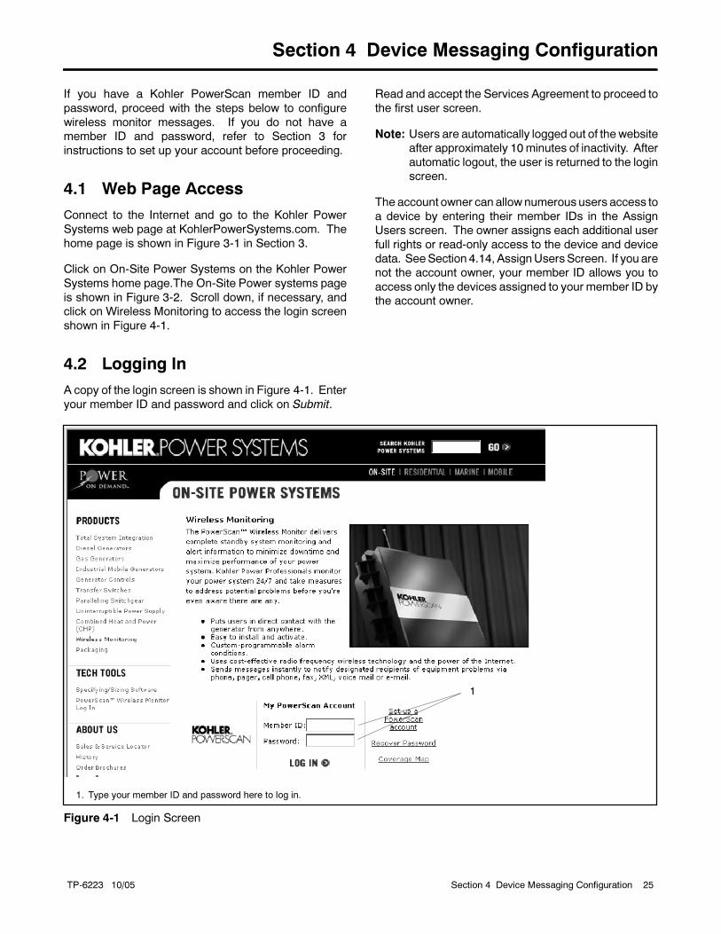
4.2 Logging In
A copy of the login screen is shown in Figure 4-1. Enter
your member ID and password and click on Submit.
Read and accept the Services Agreement to proceed to
the first user screen.
Note: Users are automatically logged out of thewebsite
after approximately 10 minutes of inactivity. After
automatic logout, the user is returned to the login
screen.
The account owner can allow numerous users access to
a device by entering their member IDs in the Assign
Users screen. The owner assigns each additional user
full rights or read-only access to the device and device
data. SeeSection 4.14, AssignUsersScreen. If you are
not the account owner, your member ID allows you to
access only the devices assigned to your member ID by
the account owner.
1
1. Type your member ID and password here to log in.
Figure 4-1 Login Screen
TP-6223 10/0526 Section 4 Device Messaging Configuration
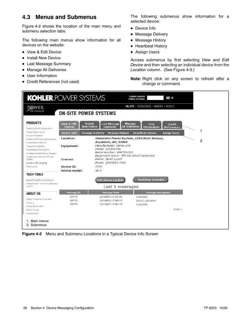
4.3 Menus and Submenus
Figure 4-2 shows the location of the main menu and
submenu selection tabs.
The following main menus show information for all
devices on the website:
View & Edit Device
Install New Device
Last Message Summary
Manage All Deliveries
User Information
Credit References (not used)
The following submenus show information for a
selected device:
Device Info
Message Delivery
Message History
Heartbeat History
Assign Users
Access submenus by first selecting View and Edit
Device and then selecting an individual device from the
Location column. (See Figure 4-3.)
Note: Right click on any screen to refresh after a
change or command.
1
1. Main menus
2. Submenus
2
Figure 4-2 Menu and Submenu Locations in a Typical Device Info Screen

TP-6223 10/05 27Section 4 Device Messaging Configuration
4.4 View and Edit Devices Screen
(View All Devices and Select a
Single Device)
Logging in and accepting the Services agreement
brings you to the View & Edit Device screen shown in
Figure 4-3. All wireless monitors installed on the
account appear in a list. To add a new device, click on
the Install New Device main menu tab. To change an
existing device, click on the device (underlined text) in
the Location column.
The View and Edit Devices screen provides a list of all
monitor devices (by Device ID) and the associated
equipment location. Clicking on the underlined text on
this screen reveals additional choices. Theuser canedit
and deactivate each device at this screen.
To deactivate a device, select Deactivate under the
ChangeStatus heading for the device to be deactivated.
Do not simply remove the device.
Note: Devices that are not deactivated continue to be
billed.
Note: An activation fee is required to reactivate a
deactivated device.
Select a device in the Location column to access the
submenus. Clicking on the equipment in the Location
column also brings up a Device Info screen specific to
the equipment and the associated PowerScan device.
See Section 4.8 for information about the Device Info
screen.
Figure 4-3 View and Edit Devices
TP-6223 10/0528 Section 4 Device Messaging Configuration
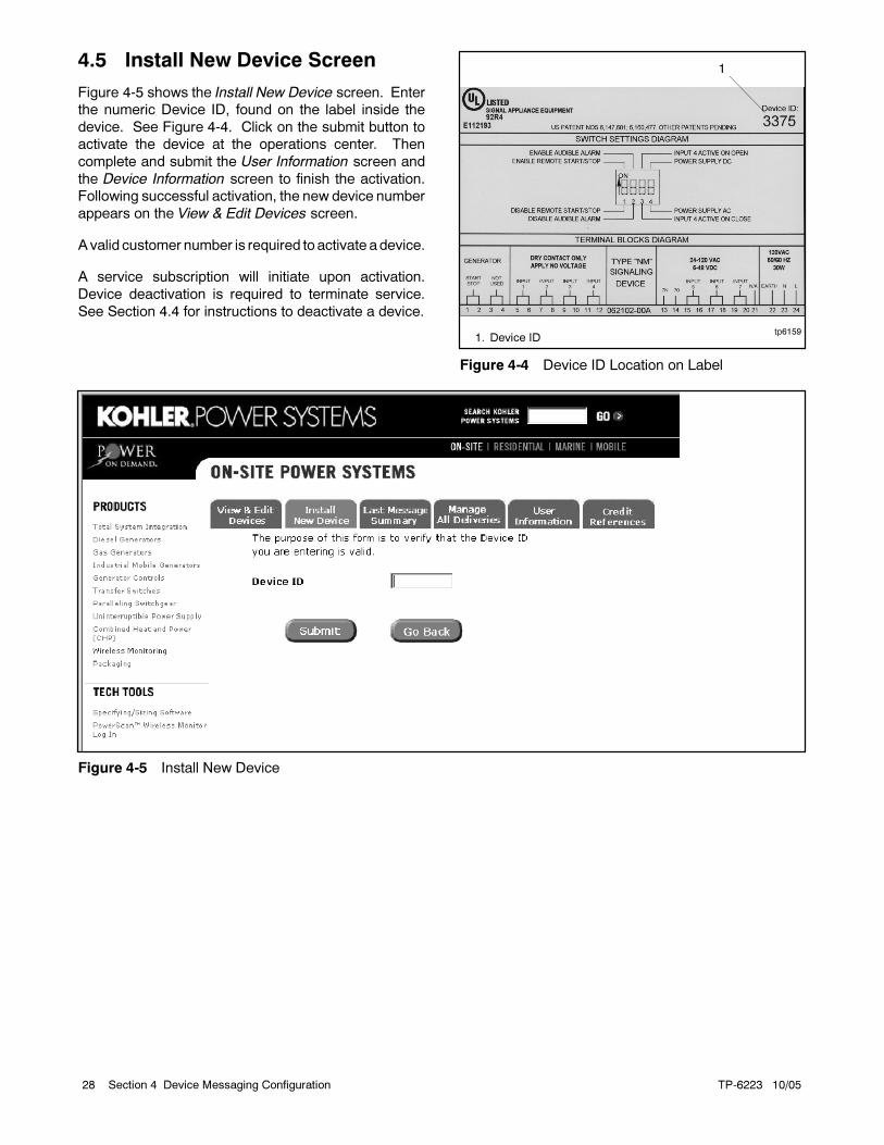
4.5 Install New Device Screen
Figure 4-5 shows the Install New Device screen. Enter
the numeric Device ID, found on the label inside the
device. See Figure 4-4. Click on the submit button to
activate the device at the operations center. Then
complete and submit the User Information screen and
the Device Information screen to finish the activation.
Following successful activation, the new device number
appears on the View & Edit Devices screen.
A valid customer number is required to activate adevice.
A service subscription will initiate upon activation.
Device deactivation is required to terminate service.
See Section 4.4 for instructions to deactivate a device.
1
tp61591. Device ID
Figure 4-4 Device ID Location on Label
Figure 4-5 Install New Device

TP-6223 10/05 29Section 4 Device Messaging Configuration
4.6 User Information Screen
(Website Manager)
Select the User Information tab at the top of any screen
after logging in to bring up the User Information screen
shown in Figure 4-6.
(123) 456--9999
(123) 456--7890
Figure 4-6 User Information
TP-6223 10/0530 Section 4 Device Messaging Configuration
The user information in this screen is not the device
location information. Do not use this screen to input
wireless monitor location information. The user
address, phone, fax, and time zone information on this
screen applies to:
The individual who obtains the website member ID
and password.
The owner or manager of the website who has full
rights.
The person who is invoiced for the monitoring service
of all devices on this website.
The person who has access to data for all monitor
devices on the website.
Note: The user and thedevice contact (set up under the
submenu Device Information screen) may be the
same individual.
Select the method of message delivery for the user at
this screen. The four fields marked telephone, fax,
e-mail, and pager are the default locations where
messages will be delivered. All fields with check boxes
must be filled in. When setting up a particular device, the
values you input automatically appear in the delivery
fields (make sure the required information is entered).
This makes configuring new devices fast and easy.
However, each device must be configured separately,
and the message delivery can be modified as required.
Once you have completed the form, click on the Submit
button.
4.7 Credit References Screen
The Credit References screen is not used.
4.8 Device Info Screen (Selecting
the Device Contact and
Configuring Equipment)
The Device Information (Device Info) screen is a
submenu selection located under the View & Edit
Devices menu. To view submenus, click on a device in
the Location column on the View & Edit Devices screen.
See Section 4.3.
Figure 4-7 shows the Device Info screen for a device
using dry contact inputs. Figure 4-8 shows the Device
Info screen for a device usingModbus communication.
This device-specific screen has a summary of the last
three messages received from the wireless monitor, the
last heartbeats received, anEdit Location selection, and
aStart/StopGenerator selection. For awirelessmonitor
connected to a device using Modbus communication,
there will also be a Control Panel selection.
Click on the Edit Device Location button to access the
data input screen. Complete the information for each
monitor device and associated equipment. All the fields
marked with check boxes are required. The address
fields are intended for the device location, not the billing
or contact location. Provide contact information for
the individual (technician or service person) that
can access the equipment connected to themonitor
device.
Note: For voice message delivery, note that the voice
synthesizer only annunciates words. Do not use
abbreviations such as St. for street or Rd. for
road. Do not use uppercase letters for words.
Uppercase letters will cause the voice
synthesizer to annunciate each letter instead of
the word.
The last fields identify the equipment served by the
monitor device. The information is intended to help a
service person prepare for maintenance or repair of the
equipment before arriving at the site. You may need to
scroll down to see the information at the bottom of the
screen.
For an activated device, the Device Information screen
lists the Last 3 Messages sent by the PowerScan
device. To view the message delivery method and
address, click on the message delivery link.
To view all of the messages sent by the PowerScan
device, click on more. View all the Last Heartbeat
messages by clicking on more. A 90-day history of all
messages is retained.
Pending Problem. “Yes” in thePending Problem column
under Last Heartbeat indicates that one or more inputs
from the monitored equipment were active at the time of
the heartbeat signal. “No” in this column indicates no
active inputs detected.
Modbus is a registered trademark of Schneider Electric

TP-6223 10/05 31Section 4 Device Messaging Configuration
John Smith
9999
123 456--7890
Figure 4-7 Device Information, Dry Contact Input Models

TP-6223 10/0532 Section 4 Device Messaging Configuration
9999
John Smith
Figure 4-8 Device Information, Modbus Communication Models

TP-6223 10/05 33Section 4 Device Messaging Configuration
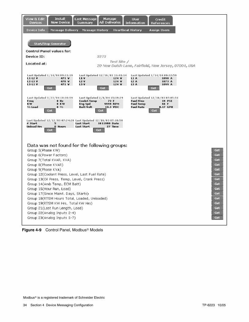
4.8.1 Control Panel
The Control Panel screen is available for monitor
devices connected to equipment using the Modbus
communication port. Select the Control Panel button in
the Device Info screen to bring up the Control Panel
screen shown in Figure 4-9.
The first time you select the Control Panel for each
device, you will be prompted to select metric or
non-metric units for displayed data. Select metric or
non-metric units to match the system used by the
equipment. Temperature will be displayed in degrees C
or F and pressure will be displayed in kPa or PSI
accordingly. The systemof units can be changed later, if
necessary, by selecting Edit Device Location in the
Device Information screen.
Note: The units selected for the wireless monitoring
system must match the units used by the
monitored equipment. The monitoring system
does not recalculate numerical values to convert
between metric and non-metric units.
The Control Panel screen lists data groups (controller
outputs) that can be selected for monitoring. Select the
Get button for each data group to obtain updated
information for that group. The information is displayed
in snapshot format and is updated each time the
corresponding Get button is selected. Information is
displayed in metric or non-metric values as selected
(next to the Control Panel selection).
Note: There is an additional charge to update each data
group using the corresponding Get button. (A
Get button selection is referred to as a Data
Request in the monitoring service fees.) Use
caution to select and update only information that
is relevant to site operation.
Once a data group is selected (by clicking the
corresponding Get button), that group continues to be
displayed in the upper part of the control panel screen. A
data group cannot be “deselected,” but additional
charges are assessed only when the correspondingGet
button is selected.
Modbus is a registered trademark of Schneider Electric
TP-6223 10/0534 Section 4 Device Messaging Configuration
Figure 4-9 Control Panel, Modbus Models
Modbus is a registered trademark of Schneider Electric
TP-6223 10/05 35Section 4 Device Messaging Configuration
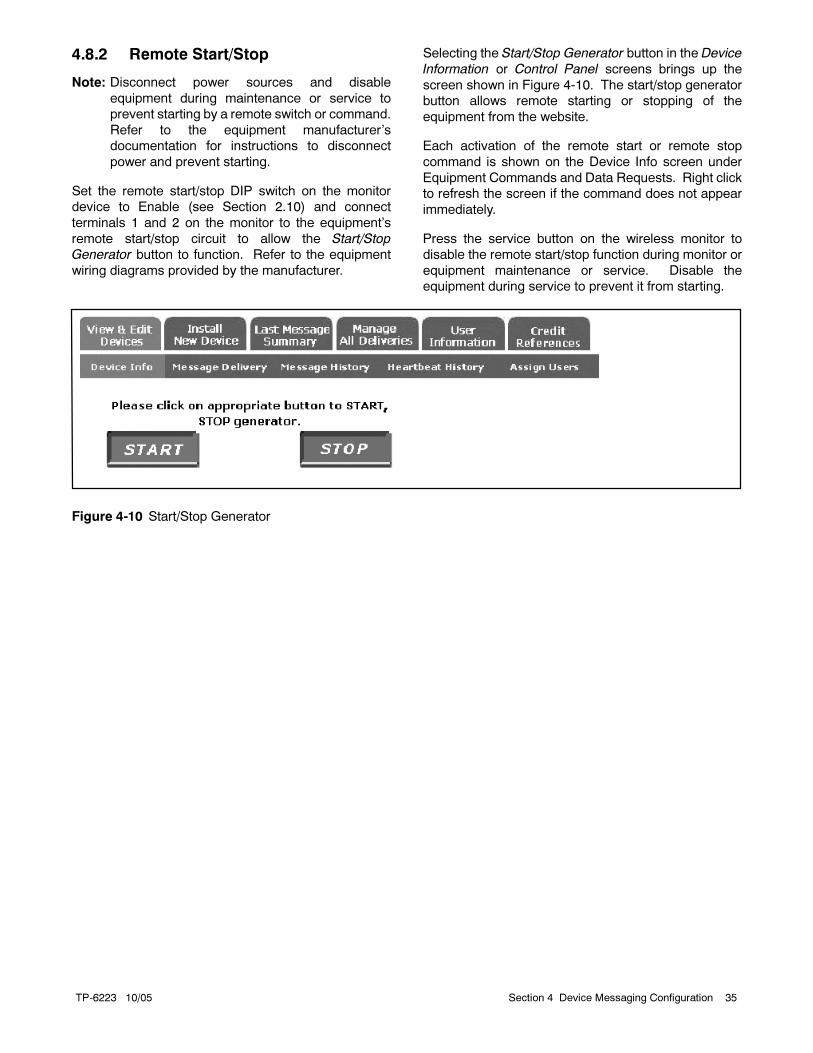
4.8.2 Remote Start/Stop
Note: Disconnect power sources and disable
equipment during maintenance or service to
prevent starting by a remote switch or command.
Refer to the equipment manufacturer’s
documentation for instructions to disconnect
power and prevent starting.
Set the remote start/stop DIP switch on the monitor
device to Enable (see Section 2.10) and connect
terminals 1 and 2 on the monitor to the equipment’s
remote start/stop circuit to allow the Start/Stop
Generator button to function. Refer to the equipment
wiring diagrams provided by the manufacturer.
Selecting the Start/Stop Generator button in the Device
Information or Control Panel screens brings up the
screen shown in Figure 4-10. The start/stop generator
button allows remote starting or stopping of the
equipment from the website.
Each activation of the remote start or remote stop
command is shown on the Device Info screen under
Equipment Commands and Data Requests. Right click
to refresh the screen if the command does not appear
immediately.
Press the service button on the wireless monitor to
disable the remote start/stop function during monitor or
equipment maintenance or service. Disable the
equipment during service to prevent it from starting.
Figure 4-10 Start/Stop Generator

TP-6223 10/0536 Section 4 Device Messaging Configuration
4.9 Last Message Summary
Screen (Alarm History for all
Website Devices)
The Last Message Summary screen, shown in
Figure 4-11, provides a listing of the last message
received from each device assigned to the account.
Click on the underlined text in the Description column to
see who successfully received the alarm message.
9999
Figure 4-11 Last Message Summary
TP-6223 10/05 37Section 4 Device Messaging Configuration
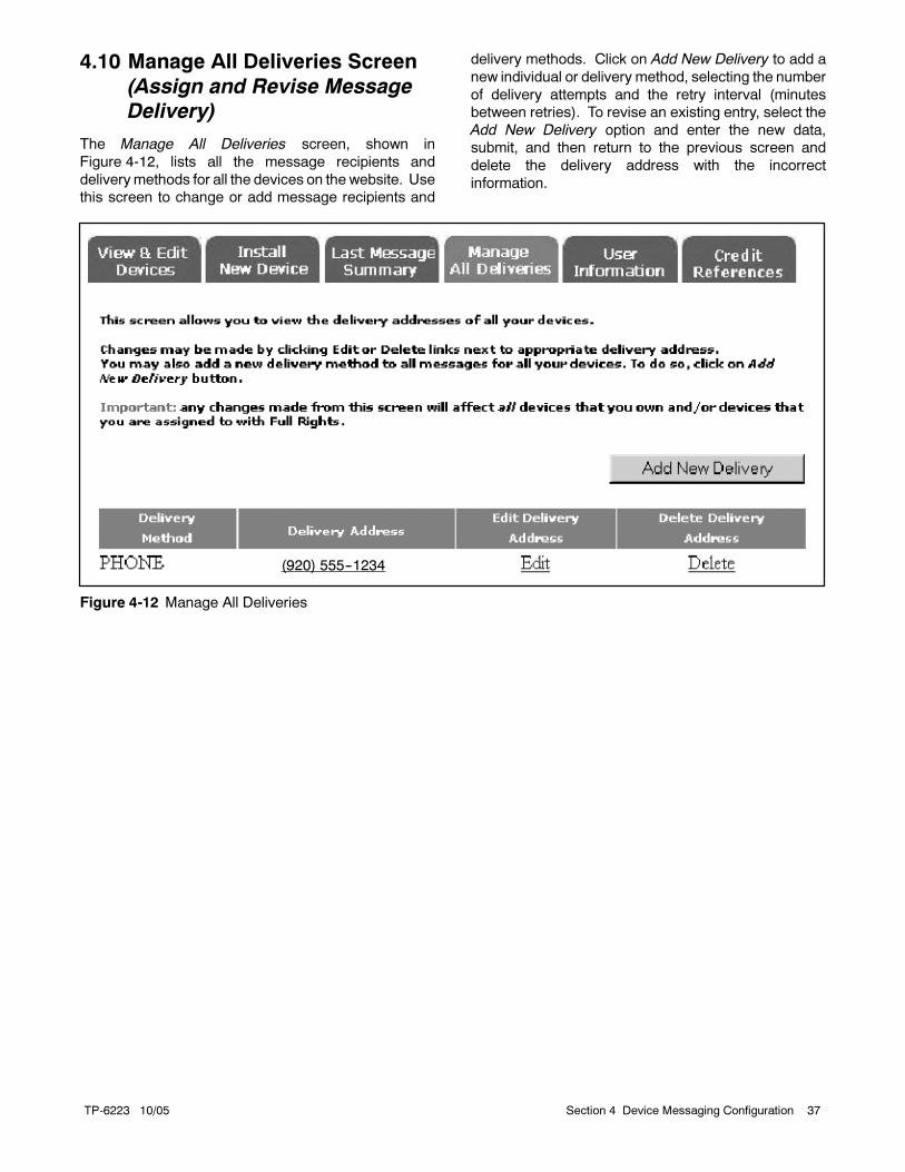
4.10 Manage All Deliveries Screen
(Assign and Revise Message
Delivery)
The Manage All Deliveries screen, shown in
Figure 4-12, lists all the message recipients and
deliverymethods for all the devices on the website. Use
this screen to change or add message recipients and
delivery methods. Click on Add New Delivery to add a
new individual or delivery method, selecting the number
of delivery attempts and the retry interval (minutes
between retries). To revise an existing entry, select the
Add New Delivery option and enter the new data,
submit, and then return to the previous screen and
delete the delivery address with the incorrect
information.
(920) 555--1234
Figure 4-12 Manage All Deliveries

TP-6223 10/0538 Section 4 Device Messaging Configuration
4.11 Message Delivery Screen
(Selecting Messages for
Device Inputs)
The Message Delivery screen is a submenu selection.
To bring up the submenus, click on a device in the
Location column on the View & Edit Devices screen.
See Section 4.3.
The Message Delivery screen, shown in Figure 4-13,
lists all messages defined for the selected device and
shows the target address (recipient) for each message.
The message delivery method can be changed on the
Message Delivery screen. Use the last column, Edit
Delivery Detail, to change the following items.
TheDelivery Attempts field determines howmany times
Kohler will attempt to deliver a message if a message is
not successfully received. The number of attempts can
also be selected on the Manage All Deliveries screen
using Add New Device.When the message is delivered
successfully, no more attempts will be made.
If the message is not successfully delivered after the
specified number of delivery attempts, an e-mail will be
sent to the account holder that the user information may
need to be changed or updated.
The Retry Interval is the time period between attempts
to deliver themessage. It is also located on theManage
All Deliveries screen.
Phone delivery messages are interactive. The
message (alarm) will not be delivered unless the the
user presses #1 on the phone during the greeting.
Attempts to direct the message to voice mail will fail.
Undeliveredmessages appear as failed deliveries in the
message description details of the Message History
screen. See Section 4.12.
Note: At this time, it is not possible to deliver amessage
to a phone extension.
(123) 456--7890
(123) 456--7890
(123) 456--7890
(123) 456--7890
(123) 456--7890
(123) 456--7890
(123) 456--7890
(123) 456--7890
(123) 456--7890
(123) 456--7890
(123) 456--7890
(123) 456--7890
Figure 4-13 Message Delivery
TP-6223 10/05 39Section 4 Device Messaging Configuration
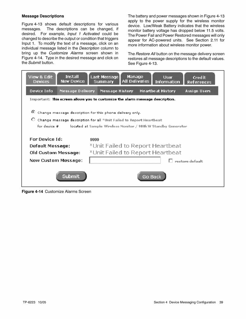
Message Descriptions
Figure 4-13 shows default descriptions for various
messages. The descriptions can be changed, if
desired. For example, Input 1 Activated could be
changed to describe the output or condition that triggers
Input 1. To modify the text of a message, click on an
individual message listed in the Description column to
bring up the Customize Alarms screen shown in
Figure 4-14. Type in the desired message and click on
the Submit button.
The battery and power messages shown in Figure 4-13
apply to the power supply for the wireless monitor
device. Low/Weak Battery indicates that the wireless
monitor battery voltage has dropped below 11.5 volts.
The Power Fail and Power Restoredmessages will only
appear for AC-powered units. See Section 2.11 for
more information about wireless monitor power.
The Restore All button on the message delivery screen
restores all message descriptions to the default values.
See Figure 4-13.
9999
Figure 4-14 Customize Alarms Screen

TP-6223 10/0540 Section 4 Device Messaging Configuration
4.12 Message History Screen
(Reviewing Message History
for Single Inputs)
The Message History screen is a submenu selection.
Click on a device in the Location column on the View &
Edit Devices screen to bring up the submenus. See
Section 4.3.
All messages that have been generated by the outputs
of a singlemonitor device are listed on this screen. Click
on an item in the Message Description column to view
detailed information on all messages for this output, the
delivery address, and the result of the delivery.
Figure 4-15 Message History

TP-6223 10/05 41Section 4 Device Messaging Configuration
4.13 Heartbeat History Screen
The Heartbeat History screen is a submenu selection.
Click on a device in the Location column on the View &
Edit Devices screen to bring up the submenus. See
Section 4.3.
Heartbeat messages are delivered every 24 hours to
indicate that the monitor device is active and
communicating. All heartbeat messages during the
past 90 days are listed on the screen. See Figure 4-16.
A missing heartbeat message could indicate that the
monitor device has lost power or a web server error has
occurred. Failure to receive a heartbeat message for a
24-hour period will be noted by a red star next to the
device on the View & Edit Devices screen. Even though
each heartbeat message has an associated time, the
actual messagemay not be displayed on the website for
several hours after reporting.
There is other information displayed on this screen (see
Figure 4-16):
Signal Strength. The strength of the signal via the cell
tower is (0--9) displayed. A signal strength of 2 or less
indicates an unreliable signal and a different device
location should be considered. Consider using an
optional high-gain antenna if a signal strength greater
than 2 cannot be obtained at the sitewith the standard
antenna.
An F in the Signal Strength column indicates the
monitor device is in the service mode and cannot
transmit messages. A monitor device in the service
mode also does not allow theStart/Stop function to be
activated via the website.
Pending Problem. “Yes” in the Pending Problem
column indicates that one or more inputs from the
monitored equipment were active at the time of the
heartbeat signal. “No” in this column indicates no
active inputs detected.
Runtime. Models using hardwire inputs display the
accumulated generator set runtime for a 24-hr. period
in tha cloumn labeled 24 hr. Run Mins. Runtimes are
collected through voltage inputs 13 and 14 on the
PowerScan device.
On models using Modbus communication, runtime
is collected through the Modbus communication
connection and accumulated from startup. The
runtime is displayed in a column labeled Total Run
Hrs. These models also display the total number of
starts in a separate column.
Figure 4-16 Heartbeat History
Modbus is a registered trademark of Schneider Electric

TP-6223 10/0542 Section 4 Device Messaging Configuration
4.14 Assign Users Screen (User
Rights)
The Assign Users screen is a submenu selection. Click
on a device in the Location column on the View & Edit
Devices screen to bring up the submenus. SeeSection
4.3.
Use the Assign Users screen to add users and define
their user rights: full rights or read-only access to
devices and device data. See Figure 4-17.
John Smith 999
Figure 4-17 Assign Users

TP-6223 10/05 Appendix 43
Appendix A Abbreviations
The following list contains abbreviations that may appear in this publication.
A, amp ampere
ABDC after bottom dead center
AC alternating current
A/D analog to digital
ADC analog to digital converter
adj. adjust, adjustment
ADV advertising dimensionaldrawing
AHWT anticipatory high watertemperature
AISI American Iron and SteelInstitute
ALOP anticipatory low oil pressure
alt. alternator
Al aluminum
ANSI American National StandardsInstitute(formerly American StandardsAssociation, ASA)
AO anticipatory only
API American Petroleum Institute
approx. approximate, approximately
AR as required, as requested
AS as supplied, as stated, assuggested
ASE American Society of Engineers
ASME American Society ofMechanical Engineers
assy. assembly
ASTM American Society for TestingMaterials
ATDC after top dead center
ATS automatic transfer switch
auto. automatic
aux. auxiliary
A/V audiovisual
avg. average
AVR automatic voltage regulator
AWG American Wire Gauge
AWM appliance wiring material
bat. battery
BBDC before bottom dead center
BC battery charger, batterycharging
BCA battery charging alternator
BCI Battery Council International
BDC before dead center
BHP brake horsepower
blk. black (paint color), block(engine)
blk. htr. block heater
BMEP brake mean effective pressure
bps bits per second
br. brass
BTDC before top dead center
Btu British thermal unit
Btu/min. British thermal units per minute
C Celsius, centigrade
cal. calorie
CARB California Air Resources Board
CB circuit breaker
cc cubic centimeter
CCA cold cranking amps
ccw. counterclockwise
CEC Canadian Electrical Code
cert. certificate, certification, certified
cfh cubic feet per hour
cfm cubic feet per minute
CG center of gravity
CID cubic inch displacement
CL centerline
cm centimeter
CMOS complementary metal oxidesubstrate (semiconductor)
cogen. cogeneration
com communications (port)
coml commercial
Coml/Rec Commercial/Recreational
conn. connection
cont. continued
CPVC chlorinated polyvinyl chloride
crit. critical
CRT cathode ray tube
CSA Canadian StandardsAssociation
CT current transformer
Cu copper
cu. in. cubic inch
cw. clockwise
CWC city water-cooled
cyl. cylinder
D/A digital to analog
DAC digital to analog converter
dB decibel
dBA decibel (A weighted)
DC direct current
DCR direct current resistance
deg., ° degree
dept. department
dia. diameter
DI/EO dual inlet/end outlet
DIN Deutsches Institut fur Normunge. V. (also Deutsche IndustrieNormenausschuss)
DIP dual inline package
DPDT double-pole, double-throw
DPST double-pole, single-throw
DS disconnect switch
DVR digital voltage regulator
E, emer. emergency (power source)
EDI electronic data interchange
EFR emergency frequency relay
e.g. for example (exempli gratia)
EG electronic governor
EGSA Electrical Generating SystemsAssociation
EIA Electronic IndustriesAssociation
EI/EO end inlet/end outlet
EMI electromagnetic interference
emiss. emission
eng. engine
EPA Environmental ProtectionAgency
EPS emergency power system
ER emergency relay
ES engineering special,engineered special
ESD electrostatic discharge
est. estimated
E-Stop emergency stop
etc. et cetera (and so forth)
exh. exhaust
ext. external
F Fahrenheit, female
fglass. fiberglass
FHM flat head machine (screw)
fl. oz. fluid ounce
flex. flexible
freq. frequency
FS full scale
ft. foot, feet
ft. lb. foot pounds (torque)
ft./min. feet per minute
g gram
ga. gauge (meters, wire size)
gal. gallon
gen. generator
genset generator set
GFI ground fault interrupter
GND, ground
gov. governor
gph gallons per hour
gpm gallons per minute
gr. grade, gross
GRD equipment ground
gr. wt. gross weight
H x W x D height by width by depth
HC hex cap
HCHT high cylinder head temperature
HD heavy duty
HET high exhaust temperature,high engine temperature
hex hexagon
Hg mercury (element)
HH hex head
HHC hex head cap
HP horsepower
hr. hour
HS heat shrink
hsg. housing
HVAC heating, ventilation, and airconditioning
HWT high water temperature
Hz hertz (cycles per second)
IC integrated circuit
ID inside diameter, identification
IEC International ElectrotechnicalCommission
IEEE Institute of Electrical andElectronics Engineers
IMS improved motor starting
in. inch
in. H2O inches of water
in. Hg inches of mercury
in. lb. inch pounds
Inc. incorporated
ind. industrial
int. internal
int./ext. internal/external
I/O input/output
IP iron pipe
ISO International Organization forStandardization
J joule
JIS Japanese Industry Standard
k kilo (1000)
K kelvin

TP-6223 10/0544 Appendix
kA kiloampere
KB kilobyte (210 bytes)
kg kilogram
kg/cm2 kilograms per squarecentimeter
kgm kilogram-meter
kg/m3 kilograms per cubic meter
kHz kilohertz
kJ kilojoule
km kilometer
kOhm, kΩ kilo-ohm
kPa kilopascal
kph kilometers per hour
kV kilovolt
kVA kilovolt ampere
kVAR kilovolt ampere reactive
kW kilowatt
kWh kilowatt-hour
kWm kilowatt mechanical
L liter
LAN local area network
L x W x H length by width by height
lb. pound, pounds
lbm/ft3 pounds mass per cubic feet
LCB line circuit breaker
LCD liquid crystal display
ld. shd. load shed
LED light emitting diode
Lph liters per hour
Lpm liters per minute
LOP low oil pressure
LP liquefied petroleum
LPG liquefied petroleum gas
LS left side
Lwa sound power level, A weighted
LWL low water level
LWT low water temperature
m meter, milli (1/1000)
M mega (106 when used with SIunits), male
m3 cubic meter
m3/min. cubic meters per minute
mA milliampere
man. manual
max. maximum
MB megabyte (220 bytes)
MCM one thousand circular mils
MCCB molded-case circuit breaker
meggar megohmmeter
MHz megahertz
mi. mile
mil one one-thousandth of an inch
min. minimum, minute
misc. miscellaneous
MJ megajoule
mJ millijoule
mm millimeter
mOhm,mΩ milliohm
MOhm,MΩ megohm
MOV metal oxide varistor
MPa megapascal
mpg miles per gallon
mph miles per hour
MS military standard
m/sec. meters per second
MTBF mean time between failure
MTBO mean time between overhauls
mtg. mounting
MW megawatt
mW milliwatt
μF microfarad
N, norm. normal (power source)
NA not available, not applicable
nat. gas natural gas
NBS National Bureau of Standards
NC normally closed
NEC National Electrical Code
NEMA National ElectricalManufacturers Association
NFPA National Fire ProtectionAssociation
Nm newton meter
NO normally open
no., nos. number, numbers
NPS National Pipe, Straight
NPSC National Pipe, Straight-coupling
NPT National Standard taper pipethread per general use
NPTF National Pipe, Taper-Fine
NR not required, normal relay
ns nanosecond
OC overcrank
OD outside diameter
OEM original equipmentmanufacturer
OF overfrequency
opt. option, optional
OS oversize, overspeed
OSHA Occupational Safety and HealthAdministration
OV overvoltage
oz. ounce
p., pp. page, pages
PC personal computer
PCB printed circuit board
pF picofarad
PF power factor
ph., ∅ phase
PHC Phillips head crimptite (screw)
PHH Phillips hex head (screw)
PHM pan head machine (screw)
PLC programmable logic control
PMG permanent-magnet generator
pot potentiometer, potential
ppm parts per million
PROM programmable read-onlymemory
psi pounds per square inch
pt. pint
PTC positive temperature coefficient
PTO power takeoff
PVC polyvinyl chloride
qt. quart, quarts
qty. quantity
R replacement (emergency)power source
rad. radiator, radius
RAM random access memory
RDO relay driver output
ref. reference
rem. remote
Res/Coml Residential/Commercial
RFI radio frequency interference
RH round head
RHM round head machine (screw)
rly. relay
rms root mean square
rnd. round
ROM read only memory
rot. rotate, rotating
rpm revolutions per minute
RS right side
RTV room temperature vulcanization
SAE Society of AutomotiveEngineers
scfm standard cubic feet per minute
SCR silicon controlled rectifier
s, sec. second
SI Systeme international d’unites,International System of Units
SI/EO side in/end out
sil. silencer
SN serial number
SPDT single-pole, double-throw
SPST single-pole, single-throw
spec,specs specification(s)
sq. square
sq. cm square centimeter
sq. in. square inch
SS stainless steel
std. standard
stl. steel
tach. tachometer
TD time delay
TDC top dead center
TDEC time delay engine cooldown
TDEN time delay emergency tonormal
TDES time delay engine start
TDNE time delay normal toemergency
TDOE time delay off to emergency
TDON time delay off to normal
temp. temperature
term. terminal
TIF telephone influence factor
TIR total indicator reading
tol. tolerance
turbo. turbocharger
typ. typical (same in multiplelocations)
UF underfrequency
UHF ultrahigh frequency
UL Underwriter’s Laboratories, Inc.
UNC unified coarse thread (was NC)
UNF unified fine thread (was NF)
univ. universal
US undersize, underspeed
UV ultraviolet, undervoltage
V volt
VAC volts alternating current
VAR voltampere reactive
VDC volts direct current
VFD vacuum fluorescent display
VGA video graphics adapter
VHF very high frequency
W watt
WCR withstand and closing rating
w/ with
w/o without
wt. weight
xfmr transformer

TP-6223 10/05 Appendix 45
Appendix B Noise and Wiring Practices
Electrical noise is an unwanted electrical signal that can
cause errors in measurement, loss of control,
malfunctions in microprocessor-based control systems,
errors in data transfer between systems over
communication links, or reductions in system
performance.
Good system design and wiring practices can minimize
noise levels and the effects of noise.
Noise, because of its random nature, is typically
characterized by frequency distribution. Many noise
sources are broad-spectrum, that is, they producemany
frequencies distributed over a wide range.
Broad-spectrum noise is particularly troublesome
because it cannot be removed easily by filtering, and
because it can affect a variety of systems in
unpredictable ways. One common source of
broad-spectrum noise is a switch, which can produce
voltage and current changes when an electrical circuit is
connected and disconnected.
Coupling is the transfer of signals between separate
circuits. Signals from one circuit become noise in
another. The amount of coupling is cumulative and is a
function of the proximity of the circuits, their orientation,
exposed area, and length of run. Minimize coupling by
the following:
Isolating circuits from each other by using separate
raceways or conduit
Separating circuits from each other by locating them
as far apart as possible
Enclosing circuits with a grounded metallic shield
such as an enclosure,metallic conduit, or cable shield
Running conductors perpendicular, rather than
parallel, to each other
Running wires loosely and randomly rather than
bundling them tightly together
Twisting a circuit’s wires together in pairs
In an industrial environment, there are typically five
types of circuits with different noise emission and
rejection capabilities. The five types of circuits are as
follows:
High-Power Distribution. Circuits to high-power
loads such as large electric motors and heaters can
emit transient high levels of broad-spectrum noise.
Loads on high-power distribution circuits are nearly
immune to noise.
General Purpose Power Distribution. Circuits to
medium-power loads such as lighting, offices, light-
duty equipment, and small motors such as fans and
pumps can emit transient, medium levels of
broad-spectrum noise. Some electronic equipment,
such as computers, emits constant levels of
broad-spectrum noise in addition to transient
broad-spectrum noise. Loads on general-purpose
circuits, except for sensitive electronic equipment,
are nearly immune to noise.
Control. Control circuits include DC circuits and
120 VAC maximum AC circuits that operate at a low
power level (less than 1 W). Typical circuits include
circuits to switches, actuators, and dry-contact relays,
including the generator engine-start circuit. Control
circuits emit transient low levels of broad-spectrum
noise and are fairly immune to noise.
Analog. Analog circuits are low-voltage DC circuits
that convey measurement information as relatively
small changes in current or voltage. Typical circuits
include those connected to the controller’s analog
inputs. Analog circuits create the lowest noise levels
and are the most sensitive to noise.
Communication and Signaling. Communication
and signaling circuits are low-voltage circuits that
convey information. Typical circuits include RS-232
and RS-485 serial communication lines, telephone
lines, and computer network lines. These circuits
create noise with frequencies related to the
communication signaling rate. These circuits have
some level of built-in noise immunity. Typical systems
will detect or correct errors caused by noise below
certain levels, but with a corresponding reduction in
the data transfer rate.
When planning an installation, separate all of these
types of circuits as much as possible to minimize the
hazards of insulation failure, accidental miswiring, and
noise coupling. For best results, install control circuits,
analog circuits, and communication and signaling
circuits separately. Combining circuit types is
unavoidable in the controller’s enclosure and some
other areas.
Note: It is very important to isolate high- and
medium-power circuits in raceways or conduit
separate from the other types of circuits.

TP-6223 10/0546 Appendix
Notes


2004, 2005 by Kohler Co. All rights reserved.
TP-6223 10/05a
KOHLER CO. Kohler, Wisconsin 53044Phone 920-565-3381, Fax 920-459-1646For the nearest sales/service outlet in theUS and Canada, phone 1-800-544-2444KohlerPowerSystems.com
Kohler Power SystemsAsia Pacific Headquarters7 Jurong Pier RoadSingapore 619159Phone (65) 6264-6422, Fax (65) 6264-6455