WIRELESS MOBILE ULTRASONIC DETECTOR …umpir.ump.edu.my/105/1/cd3285.pdf · There are several types...
24
WIRELESS MOBILE ULTRASONIC DETECTOR MUHAMMAD AB. BASITH B ABD. RAZAK This thesis is submitted as partial fulfillment of the requirements for the award of the Bachelor of Electrical Engineering (Hons.) (Electronics) Faculty of Electrical & Electronics Engineering Universiti Malaysia Pahang NOVEMBER, 2008
Transcript of WIRELESS MOBILE ULTRASONIC DETECTOR …umpir.ump.edu.my/105/1/cd3285.pdf · There are several types...
WIRELESS MOBILE ULTRASONIC DETECTOR
MUHAMMAD AB. BASITH B ABD. RAZAK
This thesis is submitted as partial fulfillment of the requirements for the award of the
Bachelor of Electrical Engineering (Hons.) (Electronics)
Faculty of Electrical & Electronics Engineering
Universiti Malaysia Pahang
NOVEMBER, 2008
ii
ABSTRACT
Nowadays wireless data transmission has become famous method of sending data.
There are several types of wireless data transmission such as Frequency Modulation
(FM), Amplitude Modulation (AM), wireless data transmission, Bluetooth, satellite
communication, wireless broadband and others. All the wireless data transmission used to
transmit data inside space platforms. Wireless data transmission method are increasing
practically and used everywhere such as video and audio data in television, security data,
computer data likes client server, turn on light or in security systems. Because of that, this
project is creating to improve the method where the design involves hardware and
software. The microcontroller unit MC68HC11A1 is programmed using assembly
language and connected to Visual Basic software using serial port DB9. In this project,
the wireless system consists of transmitter and receiver module using Radio Frequency
(RF) where it is connected to ultrasonic sensor. When the sensor detects the obstacle, it
will send the data and receives by the receiver at microcontroller unit. From the
microcontroller, the data will display at PC using Visual Basic software. Wireless FM
transmitter and receiver module with operating frequency at 433.92 MHz was chose in
order to achieve the objective of the wireless communication.
iv
TABLE OF CONTENTS
CHAPTER TITLE PAGE
TITLE PAGE
DECLARATION OF ORIGINALITY
AND EXCLUSIVENESS
DEDICATION
ACKNOLEDGEMENT i
ABSTRACT ii
ABSTRAK iii
TABLE OF CONTENTS iv
LIST OF TABLES vii
LIST OF FIGURES viii
LIST OF APPENDICES x
1 INTRODUCTION
1.1 Background 1
1.2 Objective 2
1.3 Problem statement 2
1.4 Scope of the project 3
1.5 Project methodology 4
1.6 Thesis Outline 4
2 LITERATURE RIVIEW
2.1 Air Ultrasonic Transducer 250ST/R180 6
v
2.2 Radio Frequency 9
2.3 Transmission medium 10
2.4 Transmitter & Receiver module 13
2.4.1 RCT-433-AS transmitter module 13
2.4.2 RCR-433-RP receiver module 15
2.5 Serial Port Interfacing 17
2.5.1 Serial port pins and wires 18
2.6 Microcontroller M68HC11A1 18
3 SYSTEM DESIGN
3.1 Introduction 22
3.2 Hardware design 23
3.2.1 Air Ultrasonic Ceramic
Transducers 250ST/R180 24
Ultrasonic transducer, TX1. 24
Transistor 25
CMOS timer IC 7555 26
Ultrasonic transducer, RX1 27
IC2 (N1-N3), LM324N –
Quadruple operational amplifiers 28
D1- IN4148 Silicon Epitaxial
Planar switching diode 29
3.2.2 Transmitter and Receiver design circuit
3.2.2.1 The transmitter module
with encoder 30
3.2.2.2 The receiver module
with decoder 35
3.2.2.3 Antenna design 39
3.2.3 Designing the microcontroller
vi
MC68HC11A1P circuit 41
3.2.3.1 Designing the microcontroller
MC68HC11A1P 43
3.2.3.2 Clock Circuit 44
3.2.3.3 Reset Circuit 45
3.2.3.4 Serial communication with
Microcontroller 46
3.2.3.5 WP11 software 48
3.2.3.6 THRSim 11 Software 49
4 RESULT AND DISCUSSION
4.1 Introduction 50
4.2 Visual Basic (VB) display 51
4.3 Overall hardware system 52
4.3.1 Ultrasonic transducer 54
4.3.2 Transmitter part 55
4.3.3 Receiver part 56
4.3.4 Microcontroller part 57
5 CONCLUSION AND RECOMMENDATION
5.1 Conclusion 59
5.2 Problem and solution 60
5.3 Future Recommendation of this project 61
5.4 Costing and Commercialization 61
REFERENCES 63-64
APPENDICES 65-95
1
CHAPTER 1
INTRODUCTION
This chapter discuss about the background of this project including the objective, scope
and problem statement. Than the methodology is also discussed in this chapter in order to
achieve the project objective and the scope.
1.1 Background
An ultrasonic sensor or more commonly called as a sonar sensor are widely used in
application involving range finding and object detection and avoidance. It also known as
transducers when they both transmit and receive data. An ultrasonic transducer is a
device that converts energy into ultrasound, or sound waves above the normal range of
human hearing. Sonar sensors are excellent for mobile robot applications; especially if a
robot needs to navigate through a room filled with obstacles. The critical issue especially
in construction is to find the obstacle in small place or at the dangerous places.
[Wikipedia, 2007].
Wireless mobile ultrasonic detector is designed by combining several equipments
which are the ultrasonic transducer, radio controller car, radio frequency transmitter and

2
receiver, and microcontroller MC68HC11. The wireless mobile used in the system to
make the mobile unit have more function compared to the wire mobile unit. The
ultrasonic transducer work as a sensor to interpret the echoes from the radio, while the RF
transmitter and receiver are the devices that transmit and receive the signal from the
transducer. The receiver is then connected to microcontroller MC68HC11 to display the
result.
This system transmitted information without wire so that the device can operate in
large area. Also it is very useful to find object hidden in non-visible place. The
transmitter and receiver operate using radio frequency signal that can penetrate the wall,
so the system can be used by contractors to find the obstacle in the tunnel. This will
reduce cost and time.
1.2 Objective
The objectives of this project are to:
i. Design wireless mobile ultrasonic detector.
ii. Control the mobile unit using Radio Frequency (RF).
1.3 Problem statement
Nowadays, there are many devices operating without wire and it is become
popular among people especially at job place. For example, the mobile controlled without
3
wire that can be simpler for the user. That also can be control in large area compare to the
mobile by wires that only allowed the short distance of range. Besides, the wire such as
copper is expensive because of the market price. So, cost for the system using wire will
increase and it is not cost effective. Because of this factor, wireless technology widely
used to replace the wired technology before so that it gives free movement to the device
in specified range.
1.4 Scope of the project
There are several scope considered in this project, that can be categorized in 2 element
process related between input and the output. Element 1 is a base unit as the input, while
element 2 is the controller unit that process the input and display the output as result for
the system.
i. Element one - Base unit (Input)
RF transmitter RCT-433-AS operating at 433.92 MHz.
Air Ultrasonic Transducer 250ST/R180, typically generates sound wave in
the ultrasonic range above 20 KHz.
ii. Element two – Controller Unit (Output)
RF receiver RCR-433-RP operating is at 433.92 MHz.
M68HC11 microcontroller as the brain of the system.

4
1.5 Project methodology
In order to achieve the project objective and scope, fives steps are taken to finish
successfully this project which are;
i. Literature review.
ii. Develop the system.
iii. Testing the ultrasonic transducer for functionality.
iv. Testing the transmitter and receiver circuit for functionality.
v. Complete the microcontroller circuit and download the program.
1.6 Thesis Outline
This thesis consists of five chapters including this chapter. The content of the rest
of the chapters in this thesis are outlined below;
Chapter 2 focuses on literature review of this project based on journals and
other references. Discuss about the element that is used in this project.
Chapter 3 mainly discuss on the system design of the project. It is contain
all the information and technical data of the implement system design.
This chapter including details on the progress of the project and interface
between hardware and software are explained in this chapter.

5
Chapter 4 presents the result and discussion that come from the output of
the project. It is focus on the result based on the experiment.
Chapter 5 is the last chapter which is about the overall of the project. It is
contain the conclusion and future recommendation of this project. The
several problems to complete the project and the solution to the problem
are included in this chapter. .
6
CHAPTER 2
LITERATURE REVIEW
2.0 Air Ultrasonic Transducer 250ST/R180
Air ultrasonic transducer is one of the sensor that is useful in finding objects.
Ultrasonic sound pressure is a cyclic with a frequency higher than the frequency that
human can hear. For a person that in healthy, young adult, the frequency that they can
hear is approximately about 20 KHz. Otherwise, 20 KHz serves as useful lower limit in
describing ultrasound and in this range of frequency, the product which used ultrasound
cannot operate correctly. The productions of ultrasound are used in different field and the
most well known application of this ultrasonic is its use for medication in sonography to
produce pictures of fetuses in the human womb. [Wikipedia, 2008].
Ultrasound can be used as a sensor for multiply usage such as use in Liquid Level
Monitoring, Proximity, Machine Control, Vehicle Guidance, Counting, Gauging and a
host of other applications encountered in the Process Control Industries. An ultrasonic
pulse is generated in a particular direction. If there is an object in the path of this pulse,
part or all of the pulse will be reflected back to the transmitter as an echo and can be
detected through the receiver path. The location of the target can be measured by

7
multiplying the speed of sound wave with the time interval for the echoes traveling from
transducer to the target.
There are various type of ultrasonic transducer that produce echoes, transmit and
receive the high frequency sound wave and also turning electrical energy into sound. The
Air Ultrasonic Ceramic Transducers 250ST/R180 is the best choice to this project
because it is high sensitivity and sound pressure level, excellent temperature and
humidity durability, Compact and weight and also low cost ultrasonic transducer.
[Technical data for Ultrasonic Transducer 250ST/R180, 2002].
Figure 2.0 show that a simple schematic of a generic sonar sensor when the sensor
produce the echoes in action. About 40 KHz frequency of the ultrasonic sound burst
emitted from the transducer and than the sound waves travel until reflected off of an
object and the echoes sound waves return to the transducer is call the time-of-flight. An
external timer is recoded, which can be converted to a distance measurement when
considering the speed of sound in air. As the transmitted sound waves propagate from the
transducer, they expand in the shape of a cone of angle q as depicted in Figure 2.0. This
cone defines the area over which the sonar is effective.
[ME 3200 Mechatronics Laboratory]

8
Figure 2.0: functional how sonar sensor works
This technology can be used in several applications which are for measuring such
as wind speed and the direction of the speed (anemometer), fullness of tank, and speed
through air or water. For measurement speed and direction, multiply device for detectors
are used to detect and calculates the speed from the relative distance to particular in the
air or water. For the amount of liquid in the tank, the sensor measure the distance to the
surface of the liquid. Another usage for this technology such as including humidifiers,
sonar, medical ultrasonography, burglar alarms, and non-destructive testing. All this
application uses the ultrasonic transducer as the sensor for measure distance or others.
Otherwise the technology that used ultrasonic is limited by the shapes of surface and the
density or consistency of the material like the reading of the foam on the surface in the
tank can‘t get the exact value. [wikipedia, 2008]
9
2.1 Radio Frequency
Radio frequency is one of the ranges of electromagnetic waves with a frequency
or wavelength suitable for utilization in radio communication. There are two types of
frequency that applied in radio communication which is carrier frequency and modulated
frequency. The carrier frequency waves serve as carrier of the lower frequency audio
waves and some other are modulated by video or digital information. Radio frequency
(RF) is a frequency or rate of oscillation within the range of about 3 Hz to 300 GHz.
There can be identifying by two different waves where short waves have relatively high
frequencies and long waves have relatively low frequencies. In range 3 Hz to 300 GHz, it
is similar to frequency of alternating current electrical signals where the frequency used
to produce and detect radio waves. Since most of this range is beyond the vibration rate
that most mechanical systems can respond to, RF usually refers to oscillations in
electrical circuits or electromagnetic radiation. [wikipedia, 2008]
Radio frequency signal are widely used because this signal have special properties
which is the electrical currents that oscillate at RF not shared by direct current signals. It
is easy becouse it can ionize air to create a conductive path through air. Another special
for this signal is the electromagnetic force that drives the RF current to the surface of
conductors, known as the skin effect. The signal has the ability to appear to flow through
paths that contain insulating material, likes the dielectric insulator of a capacitor.
[William Schweber, 2002. Electronic Communication System, Second edition].
The technology that used radio frequency are perform without wire, it make
easiest way for the user to send the data in large range. Data transmission without wire is
widely used nowadays because of the advantages of the technology. Wireless
communication is the transfer of information over a distance without the use of electrical
conductors or wires. The range for the transfer of the information may be in short
10
distance such as remote controller car or may in long distance. The term is commonly
used in the telecommunications industry to refer to telecommunications systems like
radio transmitter and receiver which use some form of energy to transfer information
without the use of wires. Information is transferred in this manner over both short and
long distances. It is used in two way radios, cellular telephones, personal digital assistants
(PDA‘s), and wireless networking. Other examples of wireless technology include GPS
units, garage door openers and or garage doors, wireless computer mice, keyboards and
headsets, satellite television and cordless telephones. It is used in industry or in academic.
[Wikipedia, 2008].
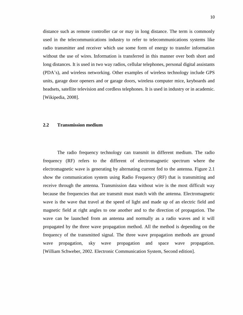
2.2 Transmission medium
The radio frequency technology can transmit in different medium. The radio
frequency (RF) refers to the different of electromagnetic spectrum where the
electromagnetic wave is generating by alternating current fed to the antenna. Figure 2.1
show the communication system using Radio Frequency (RF) that is transmitting and
receive through the antenna. Transmission data without wire is the most difficult way
because the frequencies that are transmit must match with the antenna. Electromagnetic
wave is the wave that travel at the speed of light and made up of an electric field and
magnetic field at right angles to one another and to the direction of propagation. The
wave can be launched from an antenna and normally as a radio waves and it will
propagated by the three wave propagation method. All the method is depending on the
frequency of the transmitted signal. The three wave propagation methods are ground
wave propagation, sky wave propagation and space wave propagation.
[William Schweber, 2002. Electronic Communication System, Second edition].
11
Figure 2.1: radio communication system
The first method of wave propagation is ground wave propagation and also called
as short wave band. This method is a short wave radio signal which falls in the range of 3
to 30 MHz frequency. This range of frequency normally used in radio communication
systems. It is reasonable used for radio controller car or other device which functional in
the surface of earth. This short wave signal can continue traveling to several places round
the world as long as it is in their frequency range. Another propagation method is space
wave propagation and it is a medium wave band. The range for this method is from 300
kHz to 3000 kHz and it is known as medium frequencies. This medium is alternatively
used for advance radio controller car because this medium wave band resulting in
coverage about 100kms only. There are different layer of the atmosphere such as
whether it is highly charged ionospheric layers about 100 km and higher or weather
sensitive area which is near the earth surface. So the radio waves are commonly refracted
when they travel through these different layers of atmosphere. [William Schweber, 2002.
Electronic Communication System, Second edition].

12
Figure 2.2: Radio wave propagation method
The last method of wave propagation is sky wave propagation. The wave is
propagation in ionospheric layer so it also called ionospheric propagation. Normally this
method also can be used in radio communication because wavelength of the radio
frequency used was approximately 915 meters. This type of propagation has frequency
below 30 MHz used for long distance radio communication is the result of refraction
(bending) of the wave in the ionosphere. Short wave or High Frequencies (HF) in the
range of 3-30 MHz propagates through this invisible layer which consists of charged
particles located at altitudes of between 250 and 400 km in the atmosphere surrounding
the Earth. An ionized layer is formed in the upper part of the Earth's atmosphere. Like
space wave propagation, this ionosphere has different sub layer so the different range of
frequencies are propagated through the sub layers. .
[William Schweber, 2002. Electronic Communication System, Second edition]
13
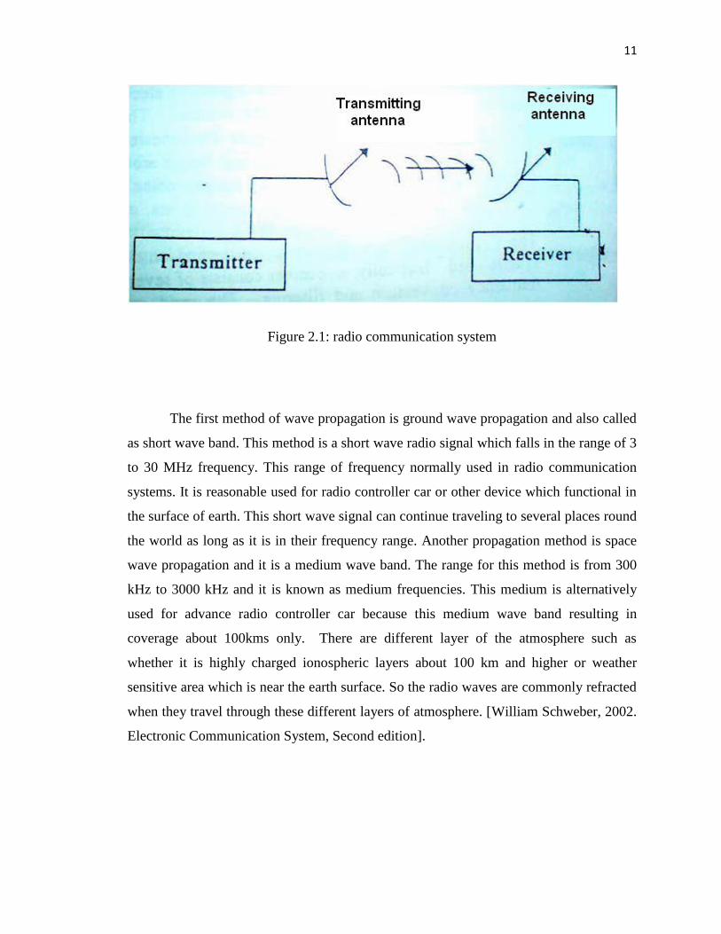
2.3 Transmitter & Receiver module
The intended hardware for this driver is the Radiotronix RCT-433-AS transmitter
and the Radiotronix RCR-433-RP receiver chips interfaced to the MCU through Port D.0
and D.1, the USART TX and RX ports. The intended circuit diagrams on the connections
of these chips are provided in figure 2.3 below. Additionally, for more information, refer
appendix A.
Figure 2.3: The intended circuit diagrams on the connections of the chips
2.3.1 RCT-433-AS transmitter module
The RCT-433-AS is ideal for remote control applications where low cost and
longer range is required. The transmitter operates from a 1.5-12V supply, making it
suitable for battery-powered applications. For this type of transmitter, the accurate
frequency control is ensuring by employs a SAW-stabilized oscillator and it is for the
14
best range performance. Output power and harmonic emissions are easy to control,
making FCC and ETSI compliance easy. [Reference manual RCT-433-AS,2002]
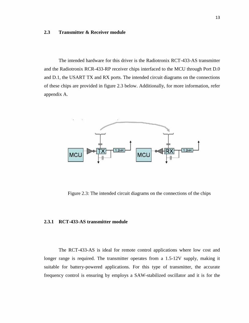
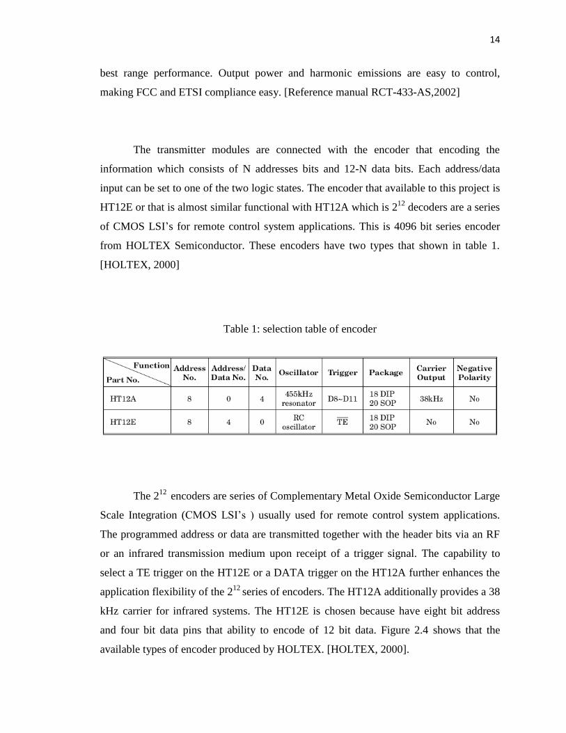
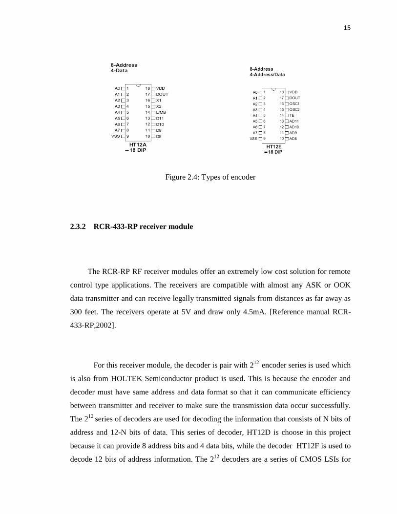
The transmitter modules are connected with the encoder that encoding the
information which consists of N addresses bits and 12-N data bits. Each address/data
input can be set to one of the two logic states. The encoder that available to this project is
HT12E or that is almost similar functional with HT12A which is 212
decoders are a series
of CMOS LSI‘s for remote control system applications. This is 4096 bit series encoder
from HOLTEX Semiconductor. These encoders have two types that shown in table 1.
[HOLTEX, 2000]
Table 1: selection table of encoder
The 212
encoders are series of Complementary Metal Oxide Semiconductor Large
Scale Integration (CMOS LSI‘s ) usually used for remote control system applications.
The programmed address or data are transmitted together with the header bits via an RF
or an infrared transmission medium upon receipt of a trigger signal. The capability to
select a TE trigger on the HT12E or a DATA trigger on the HT12A further enhances the
application flexibility of the 212
series of encoders. The HT12A additionally provides a 38
kHz carrier for infrared systems. The HT12E is chosen because have eight bit address
and four bit data pins that ability to encode of 12 bit data. Figure 2.4 shows that the
available types of encoder produced by HOLTEX. [HOLTEX, 2000].
15
Figure 2.4: Types of encoder
2.3.2 RCR-433-RP receiver module
The RCR-RP RF receiver modules offer an extremely low cost solution for remote
control type applications. The receivers are compatible with almost any ASK or OOK
data transmitter and can receive legally transmitted signals from distances as far away as
300 feet. The receivers operate at 5V and draw only 4.5mA. [Reference manual RCR-
433-RP,2002].
For this receiver module, the decoder is pair with 212
encoder series is used which
is also from HOLTEK Semiconductor product is used. This is because the encoder and
decoder must have same address and data format so that it can communicate efficiency
between transmitter and receiver to make sure the transmission data occur successfully.
The 212
series of decoders are used for decoding the information that consists of N bits of
address and 12-N bits of data. This series of decoder, HT12D is choose in this project
because it can provide 8 address bits and 4 data bits, while the decoder HT12F is used to
decode 12 bits of address information. The 212
decoders are a series of CMOS LSIs for

16
remote control system applications. They are paired with Holtek's 212
series of encoders.
[HOLTEK, 2000].
The 212
series of encoders is already programmed to transmit the data by carrier
using RF or an IR transmission medium while the decoders receive serial addresses and
data from the encoders. This encoder and decoder must set at the same address to make
sure transmit and receive data is occurred successfully. In order to get the right
information that is transmitted, they compare the serial input data three times
continuously with their local addresses to confirm if an error occurred. If no error or
unmatched codes are found, the input data codes are decoded and then transferred to the
output pins. At the VT pin (pin 17) it is goes high to indicate a valid transmission. Table
2 shows the selection of decode type that is suit with design of this project. The HT12D
type of decoder is chosen to pair with encoder HT12E. [HOLTEK, 2000].
Table 2: Selection table of decoders.
The application using the 212
series of encoders is in burglar alarm system, smoke
and fire alarm system, car door controllers, garage door controllers, car alarm systems,
security systems, cordless telephones and other remote control system that used radio
frequency (RF) signal. Figure 2.5 shows the type of decoder that available in market that
is suit with design for application in table 2. [HOLTEK, 2000].

17
Figure 2.5: Type of decoder 212
series available.
2.4 Serial Port Interfacing
The serial port is an I/O (Input/Output) device. Serial port interfacing is the
simple and inexpensive method to make connect between hardware and computer. It is
used to for building computer controller devices and projects. It is used widely nowadays
because the simplicity and ease of programming and most popular in electronics hobbyist
world. This serial port often used in Computer controlled robots, Atmel/PIC
programmers, home automation, microcontroller project and etc. The serial and parallel
port connector in the rear panel of the PC. It is a 25 pin female (DB25), a 9 pin male
(DB9), and a 15 pin female (DB15) connector each.
18
2.4.1 Serial port pins and wires
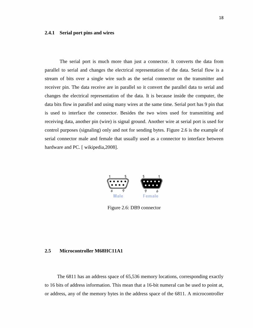
The serial port is much more than just a connector. It converts the data from
parallel to serial and changes the electrical representation of the data. Serial flow is a
stream of bits over a single wire such as the serial connector on the transmitter and
receiver pin. The data receive are in parallel so it convert the parallel data to serial and
changes the electrical representation of the data. It is because inside the computer, the
data bits flow in parallel and using many wires at the same time. Serial port has 9 pin that
is used to interface the connector. Besides the two wires used for transmitting and
receiving data, another pin (wire) is signal ground. Another wire at serial port is used for
control purposes (signaling) only and not for sending bytes. Figure 2.6 is the example of
serial connector male and female that usually used as a connector to interface between
hardware and PC. [ wikipedia,2008].
Figure 2.6: DB9 connector
2.5 Microcontroller M68HC11A1
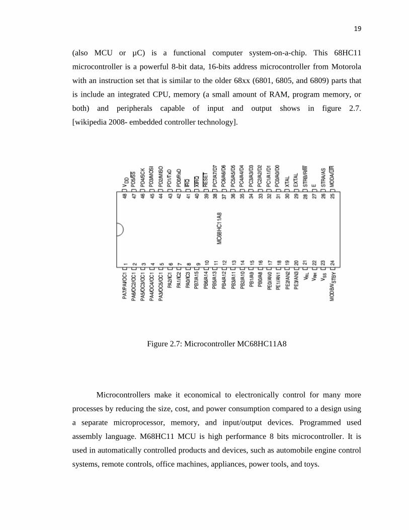
The 6811 has an address space of 65,536 memory locations, corresponding exactly
to 16 bits of address information. This mean that a 16-bit numeral can be used to point at,
or address, any of the memory bytes in the address space of the 6811. A microcontroller
19
(also MCU or µC) is a functional computer system-on-a-chip. This 68HC11
microcontroller is a powerful 8-bit data, 16-bits address microcontroller from Motorola
with an instruction set that is similar to the older 68xx (6801, 6805, and 6809) parts that
is include an integrated CPU, memory (a small amount of RAM, program memory, or
both) and peripherals capable of input and output shows in figure 2.7.
[wikipedia 2008- embedded controller technology].
Figure 2.7: Microcontroller MC68HC11A8
Microcontrollers make it economical to electronically control for many more
processes by reducing the size, cost, and power consumption compared to a design using
a separate microprocessor, memory, and input/output devices. Programmed used
assembly language. M68HC11 MCU is high performance 8 bits microcontroller. It is
used in automatically controlled products and devices, such as automobile engine control
systems, remote controls, office machines, appliances, power tools, and toys.